WO2014118894A1 - 内燃機関の制御装置 - Google Patents
内燃機関の制御装置 Download PDFInfo
- Publication number
- WO2014118894A1 WO2014118894A1 PCT/JP2013/051914 JP2013051914W WO2014118894A1 WO 2014118894 A1 WO2014118894 A1 WO 2014118894A1 JP 2013051914 W JP2013051914 W JP 2013051914W WO 2014118894 A1 WO2014118894 A1 WO 2014118894A1
- Authority
- WO
- WIPO (PCT)
- Prior art keywords
- fuel ratio
- air
- voltage
- exhaust
- current
- Prior art date
- Legal status (The legal status is an assumption and is not a legal conclusion. Google has not performed a legal analysis and makes no representation as to the accuracy of the status listed.)
- Ceased
Links
Images






Classifications
-
- F—MECHANICAL ENGINEERING; LIGHTING; HEATING; WEAPONS; BLASTING
- F02—COMBUSTION ENGINES; HOT-GAS OR COMBUSTION-PRODUCT ENGINE PLANTS
- F02D—CONTROLLING COMBUSTION ENGINES
- F02D41/00—Electrical control of supply of combustible mixture or its constituents
- F02D41/02—Circuit arrangements for generating control signals
- F02D41/14—Introducing closed-loop corrections
- F02D41/1438—Introducing closed-loop corrections using means for determining characteristics of the combustion gases; Sensors therefor
- F02D41/1444—Introducing closed-loop corrections using means for determining characteristics of the combustion gases; Sensors therefor characterised by the characteristics of the combustion gases
- F02D41/1454—Introducing closed-loop corrections using means for determining characteristics of the combustion gases; Sensors therefor characterised by the characteristics of the combustion gases the characteristics being an oxygen content or concentration or the air-fuel ratio
-
- F—MECHANICAL ENGINEERING; LIGHTING; HEATING; WEAPONS; BLASTING
- F02—COMBUSTION ENGINES; HOT-GAS OR COMBUSTION-PRODUCT ENGINE PLANTS
- F02D—CONTROLLING COMBUSTION ENGINES
- F02D41/00—Electrical control of supply of combustible mixture or its constituents
- F02D41/02—Circuit arrangements for generating control signals
- F02D41/14—Introducing closed-loop corrections
- F02D41/1438—Introducing closed-loop corrections using means for determining characteristics of the combustion gases; Sensors therefor
- F02D41/1439—Introducing closed-loop corrections using means for determining characteristics of the combustion gases; Sensors therefor characterised by the position of the sensor
- F02D41/1441—Plural sensors
-
- F—MECHANICAL ENGINEERING; LIGHTING; HEATING; WEAPONS; BLASTING
- F02—COMBUSTION ENGINES; HOT-GAS OR COMBUSTION-PRODUCT ENGINE PLANTS
- F02D—CONTROLLING COMBUSTION ENGINES
- F02D41/00—Electrical control of supply of combustible mixture or its constituents
- F02D41/02—Circuit arrangements for generating control signals
- F02D41/14—Introducing closed-loop corrections
- F02D41/1438—Introducing closed-loop corrections using means for determining characteristics of the combustion gases; Sensors therefor
- F02D41/1444—Introducing closed-loop corrections using means for determining characteristics of the combustion gases; Sensors therefor characterised by the characteristics of the combustion gases
- F02D41/1454—Introducing closed-loop corrections using means for determining characteristics of the combustion gases; Sensors therefor characterised by the characteristics of the combustion gases the characteristics being an oxygen content or concentration or the air-fuel ratio
- F02D41/1456—Introducing closed-loop corrections using means for determining characteristics of the combustion gases; Sensors therefor characterised by the characteristics of the combustion gases the characteristics being an oxygen content or concentration or the air-fuel ratio with sensor output signal being linear or quasi-linear with the concentration of oxygen
-
- G—PHYSICS
- G01—MEASURING; TESTING
- G01N—INVESTIGATING OR ANALYSING MATERIALS BY DETERMINING THEIR CHEMICAL OR PHYSICAL PROPERTIES
- G01N27/00—Investigating or analysing materials by the use of electric, electrochemical, or magnetic means
- G01N27/26—Investigating or analysing materials by the use of electric, electrochemical, or magnetic means by investigating electrochemical variables; by using electrolysis or electrophoresis
- G01N27/403—Cells and electrode assemblies
- G01N27/406—Cells and probes with solid electrolytes
- G01N27/4065—Circuit arrangements specially adapted therefor
-
- F—MECHANICAL ENGINEERING; LIGHTING; HEATING; WEAPONS; BLASTING
- F02—COMBUSTION ENGINES; HOT-GAS OR COMBUSTION-PRODUCT ENGINE PLANTS
- F02D—CONTROLLING COMBUSTION ENGINES
- F02D41/00—Electrical control of supply of combustible mixture or its constituents
- F02D41/02—Circuit arrangements for generating control signals
- F02D41/14—Introducing closed-loop corrections
- F02D41/1401—Introducing closed-loop corrections characterised by the control or regulation method
-
- F—MECHANICAL ENGINEERING; LIGHTING; HEATING; WEAPONS; BLASTING
- F02—COMBUSTION ENGINES; HOT-GAS OR COMBUSTION-PRODUCT ENGINE PLANTS
- F02D—CONTROLLING COMBUSTION ENGINES
- F02D45/00—Electrical control not provided for in groups F02D41/00 - F02D43/00
-
- G—PHYSICS
- G01—MEASURING; TESTING
- G01N—INVESTIGATING OR ANALYSING MATERIALS BY DETERMINING THEIR CHEMICAL OR PHYSICAL PROPERTIES
- G01N27/00—Investigating or analysing materials by the use of electric, electrochemical, or magnetic means
- G01N27/26—Investigating or analysing materials by the use of electric, electrochemical, or magnetic means by investigating electrochemical variables; by using electrolysis or electrophoresis
- G01N27/403—Cells and electrode assemblies
-
- G—PHYSICS
- G01—MEASURING; TESTING
- G01N—INVESTIGATING OR ANALYSING MATERIALS BY DETERMINING THEIR CHEMICAL OR PHYSICAL PROPERTIES
- G01N27/00—Investigating or analysing materials by the use of electric, electrochemical, or magnetic means
- G01N27/26—Investigating or analysing materials by the use of electric, electrochemical, or magnetic means by investigating electrochemical variables; by using electrolysis or electrophoresis
- G01N27/403—Cells and electrode assemblies
- G01N27/406—Cells and probes with solid electrolytes
- G01N27/407—Cells and probes with solid electrolytes for investigating or analysing gases
- G01N27/4075—Composition or fabrication of the electrodes and coatings thereon, e.g. catalysts
- G01N27/4076—Reference electrodes or reference mixtures
Definitions
- the present invention relates to a control device for an internal combustion engine that controls the internal combustion engine in accordance with the output of an air-fuel ratio sensor.
- Patent Document 1 to 6 a control device for an internal combustion engine in which an air-fuel ratio sensor is provided in an exhaust passage of the internal combustion engine and the amount of fuel supplied to the internal combustion engine based on the output of the air-fuel ratio sensor is widely known (for example, Patent Document 1 to 6).
- the first electrode exposed to the exhaust gas flowing through the exhaust passage as the air-fuel ratio sensor, the second electrode exposed to the atmosphere, the first electrode and the second electrode, A sensor including a solid electrolyte layer such as zirconia disposed between the two is used.
- this air-fuel ratio sensor detects the air-fuel ratio of exhaust gas (hereinafter also referred to as “exhaust air-fuel ratio”), a voltage of 0.4 V is applied between these electrodes, and the current flowing between these electrodes is the output current. Detected as The exhaust air / fuel ratio is calculated based on this output current.
- JP 2004-316553 A JP 2005-351096 A JP 2003-329637 A JP-A-8-232723 JP 2009-162139 A JP 2001-234787 A JP 2000-356618 A
- an air-fuel ratio sensor as described in Patent Document 1 is generally configured to have an output characteristic indicated by a solid line A in FIG. That is, in such an air-fuel ratio sensor, the output current from the air-fuel ratio sensor increases as the exhaust air-fuel ratio increases (that is, as the exhaust air-fuel ratio becomes leaner).
- such an air-fuel ratio sensor is configured such that the output current becomes zero when the exhaust air-fuel ratio is the stoichiometric air-fuel ratio.
- the slope in FIG. 2, that is, the ratio of the increase amount of the output current to the increase amount of the exhaust air-fuel ratio (hereinafter referred to as “output current change rate”) is not necessarily the same even through the same production process. Even a type of air-fuel ratio sensor will vary among individuals. In addition, even in the same air-fuel ratio sensor, the output current change rate changes due to deterioration over time. As a result, even if the same type of sensor is used, the rate of change in the output current decreases as shown by the broken line B in FIG. The rate of current change will increase.
- the output current of the air-fuel ratio sensor varies depending on the sensor used, the period of use, and the like. For example, when the air-fuel ratio sensor has output characteristics as indicated by the solid line A, the output current when measuring the exhaust gas having an air-fuel ratio of af 1 is I 2 . However, when the air-fuel ratio sensor has output characteristics as indicated by the broken line B or the alternate long and short dash line C, the output currents when measuring the exhaust gas having an air-fuel ratio of af 1 are I 1 and I, respectively. 3 , resulting in an output current different from I 2 described above.
- such an air-fuel ratio sensor can accurately detect that the stoichiometric air-fuel ratio and the stoichiometric air-fuel ratio are rich and lean.
- the air-fuel ratio of the exhaust gas is not the stoichiometric air-fuel ratio, its absolute The value (that is, the rich degree or the lean degree) could not be accurately detected.
- an object of the present invention is to provide an internal combustion engine using an air-fuel ratio sensor that can detect the absolute value of the air-fuel ratio of the exhaust gas even when the air-fuel ratio of the exhaust gas is not the stoichiometric air-fuel ratio. It is to provide an engine control device.
- the first invention includes an air-fuel ratio sensor provided in an exhaust passage of the internal combustion engine, and an engine control device that controls the internal combustion engine in accordance with the output of the air-fuel ratio sensor.
- the air-fuel ratio sensor changes the applied voltage at which the output current becomes zero according to the exhaust air-fuel ratio, and when the exhaust air-fuel ratio is the stoichiometric air-fuel ratio,
- the air-fuel ratio sensor detects the air-fuel ratio of the exhaust gas by the air-fuel ratio sensor
- the applied voltage in the air-fuel ratio sensor is fixed to a constant voltage, and the output current increases accordingly.
- the constant voltage is output when the exhaust air / fuel ratio is the stoichiometric air / fuel ratio and is different from the voltage at which the output current becomes zero, and the exhaust air / fuel ratio is different from the stoichiometric air / fuel ratio.
- Stream is a voltage becomes zero, the control device of the internal combustion engine is provided.
- the air-fuel ratio sensor includes a first electrode exposed to an exhaust gas that is an air-fuel ratio detection target and a second atmosphere exposed to a reference atmosphere via a diffusion rate controlling layer.
- the applied voltage is a voltage applied by a voltage application device
- the air-fuel ratio sensor includes a current increasing region in which an output current increases as the applied voltage increases for each exhaust air-fuel ratio, and the diffusion
- the current increase region is a voltage region in which the increase amount of the output current with respect to the increase amount of the applied voltage is smaller than the current increase region. If the air-fuel ratio is the stoichiometric air-fuel ratio A voltage of the current slightly region.
- the air-fuel ratio sensor is configured to have a limit current region that is a voltage region in which the output current becomes a limit current for each exhaust air-fuel ratio, and The voltage is a voltage within the limit current region when the exhaust air-fuel ratio is the stoichiometric air-fuel ratio.
- the air-fuel ratio sensor is configured such that, for each exhaust air-fuel ratio, the relationship between the applied voltage and the output current is a voltage at which the output current increases in proportion to an increase in the applied voltage.
- a proportional region that is a region
- a water decomposition region that is a voltage region in which an output current changes according to a change in applied voltage due to the occurrence of water decomposition
- a voltage region between the proportional region and the water decomposition region is a voltage in the intermediate region when the exhaust air-fuel ratio is the stoichiometric air-fuel ratio.
- the constant voltage is a voltage at which the output current becomes zero when the exhaust air-fuel ratio is 1% higher than the stoichiometric air-fuel ratio, and the exhaust air-fuel ratio is 1% below the stoichiometric air-fuel ratio.
- the output current is set to a voltage between zero.
- the air-fuel ratio sensor outputs the output current up to the first inflection point as the applied voltage increases with respect to the relationship between the applied voltage and the output current for each exhaust air-fuel ratio.
- the output current increases from the first inflection point to the second inflection point as the applied voltage increases, and the output current increases from the second inflection point as the applied voltage increases.
- the voltage region between the inflection point and the second inflection point is configured such that the increase amount of the output current with respect to the increase amount of the applied voltage is smaller than the other voltage region, and the constant voltage is the exhaust air-fuel ratio. Is a voltage between the first inflection point and the second inflection point when is the stoichiometric air-fuel ratio.
- the air-fuel ratio sensor is exposed to an exhaust gas that is an air-fuel ratio detection target through a diffusion rate-determining layer, and a second electrode that is exposed to a reference atmosphere.
- the diffusion control layer is formed of alumina, the applied voltage is a voltage applied by a voltage application device, and the constant voltage is set to 0.1 V or more and 0.9 V or less.
- the air-fuel ratio sensor includes a first electrode that is exposed to an exhaust gas that is an air-fuel ratio detection target via a diffusion-controlling layer, and a reference atmosphere.
- a current detection device that detects a current flowing between the first electrode and the second electrode, the applied voltage is a voltage applied by a voltage application device, and the output current is the current detection The current detected by the device.
- the air-fuel ratio sensor includes a measured gas chamber into which exhaust gas, which is an air-fuel ratio detection target, is allowed to flow, and a pump current. Accordingly, a pump cell for pumping and pumping oxygen to and from the exhaust gas in the measured gas chamber, and a reference cell for changing the detected reference current according to the air-fuel ratio in the measured gas chamber.
- the reference cell includes a first electrode exposed to the exhaust gas in the measured gas chamber directly or via a diffusion-controlled layer, a second electrode exposed to a reference atmosphere, the first electrode, A solid electrolyte layer disposed between the second electrode and the air-fuel ratio sensor, wherein the air-fuel ratio sensor applies a voltage between the first electrode and the second electrode of the reference cell;
- the current flowing between the first and second electrodes of the reference cell A reference current detection device that detects the reference current, a pump current control device that controls the pump current supplied to the pump cell so that the reference current detected by the reference current detection device becomes zero, and detects the pump current
- the applied voltage is a reference voltage applied by the reference voltage applying device, and the output current is a pump current detected by the pump current detecting device.
- the engine control device determines in advance that the exhaust air-fuel ratio is different from the stoichiometric air-fuel ratio when the output current of the air-fuel ratio sensor becomes zero. It is determined that the air-fuel ratio is set.
- the internal combustion engine is an exhaust purification catalyst capable of storing oxygen provided in the exhaust passage upstream of the air-fuel ratio sensor in the exhaust flow direction.
- the constant voltage is set to a voltage at which the output current becomes zero when the exhaust air-fuel ratio is a predetermined rich determination air-fuel ratio that is richer than the stoichiometric air-fuel ratio.
- the engine control device is capable of controlling an air-fuel ratio of exhaust gas flowing into the exhaust purification catalyst, and when an output current of the air-fuel ratio sensor becomes zero or less.
- the target air-fuel ratio of the exhaust gas flowing into the exhaust purification catalyst is made leaner than the stoichiometric air-fuel ratio.
- the engine control device wherein the oxygen storage amount of the exhaust purification catalyst is less than the maximum oxygen storage amount when the output current of the air-fuel ratio sensor becomes zero or less.
- Oxygen storage amount increasing means for continuously or intermittently making the target air-fuel ratio of the exhaust gas flowing into the exhaust purification catalyst leaner than the stoichiometric air-fuel ratio until the predetermined storage amount is reached, and oxygen storage of the exhaust purification catalyst When the amount exceeds the predetermined storage amount, the target air-fuel ratio is continuously or intermittently stoichiometrically reduced so that the oxygen storage amount decreases toward zero without reaching the maximum oxygen storage amount.
- an oxygen storage amount reducing means for making it richer.
- the difference is larger than the difference between the average value of the target air-fuel ratio and the stoichiometric air-fuel ratio during a period in which the oxygen storage amount reducing means is continuously or intermittently made richer than the stoichiometric air-fuel ratio.
- the oxygen storage amount increasing means continuously maintains the target air-fuel ratio leaner than the stoichiometric air-fuel ratio.
- the oxygen storage amount reducing means continuously maintains the target air-fuel ratio richer than the stoichiometric air-fuel ratio.
- the engine control system further comprises an upstream air-fuel ratio sensor provided in the exhaust passage upstream of the exhaust purification catalyst in the exhaust flow direction.
- the apparatus controls the air-fuel ratio of the exhaust gas flowing into the exhaust purification catalyst so that the air-fuel ratio detected by the upstream air-fuel ratio sensor becomes the target air-fuel ratio.
- the upstream air-fuel ratio sensor is configured such that the applied voltage at which the output current becomes zero changes according to the exhaust air-fuel ratio and the exhaust air-fuel ratio is the stoichiometric air-fuel ratio.
- the applied voltage in the upstream air-fuel ratio sensor is increased, the output current is increased accordingly.
- the applied voltage in the upstream air-fuel ratio sensor is lower than the applied voltage of the air-fuel ratio sensor. .
- the applied voltage in the upstream air-fuel ratio sensor is set to a voltage at which the output current becomes zero when the exhaust air-fuel ratio is the stoichiometric air-fuel ratio.
- the upstream air-fuel ratio sensor includes a first electrode that is exposed to an exhaust gas that is an air-fuel ratio detection target via a diffusion rate-limiting layer, and a reference atmosphere.
- a second electrode to be exposed a solid electrolyte layer disposed between the first electrode and the second electrode; and a voltage applying device for applying a voltage between the first electrode and the second electrode;
- a current detecting device for detecting a current flowing between the first electrode and the second electrode, and an applied voltage in the upstream air-fuel ratio sensor is applied by a voltage applying device of the upstream air-fuel ratio sensor.
- the output current in the upstream air-fuel ratio sensor is the current detected by the current detector of the upstream air-fuel ratio sensor.
- the upstream air-fuel ratio sensor includes a measured gas chamber into which exhaust gas, which is an air-fuel ratio detection target, flows, and the measured air flow rate according to the pump current.
- a pump cell for pumping and pumping oxygen to and from the exhaust gas in the gas chamber; and a reference cell for changing a detected reference current in accordance with an air-fuel ratio in the measured gas chamber.
- the reference cell of the fuel ratio sensor includes a first electrode exposed to the exhaust gas in the measured gas chamber directly or via a diffusion-controlled layer, a second electrode exposed to a reference atmosphere, and the first electrode
- a reference voltage applying device including a solid electrolyte layer disposed between the second electrode and the upstream air-fuel ratio sensor for applying a voltage between the first electrode and the second electrode of the reference cell.
- a reference current detection device that detects current flowing between them as the reference current
- a pump current control device that controls the pump current supplied to the pump cell so that the reference current detected by the reference current detection device becomes zero
- a pump current detecting device for detecting the pump current, and the applied voltage in the upstream air-fuel ratio sensor is a reference voltage applied by a reference voltage applying device of the upstream air-fuel ratio sensor, and the upstream air-fuel ratio
- the output current in the sensor is the pump current detected by the pump current detector of the upstream air-fuel ratio sensor.
- the internal combustion engine is a downstream side capable of storing oxygen provided in the exhaust passage on the downstream side in the exhaust flow direction from the air-fuel ratio sensor.
- An exhaust purification catalyst is further provided.
- a control device for an internal combustion engine using an air-fuel ratio sensor capable of detecting an absolute value of an air-fuel ratio of exhaust gas even when the air-fuel ratio of the exhaust gas is not a stoichiometric air-fuel ratio.
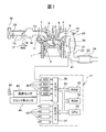
- FIG. 1 is a diagram schematically showing an internal combustion engine in which a control device of the present invention is used.
- FIG. 2 is a diagram showing output characteristics of the air-fuel ratio sensor.
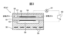
- FIG. 3 is a schematic cross-sectional view of the air-fuel ratio sensor.
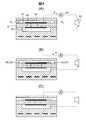
- FIG. 4 is a diagram schematically showing the operation of the air-fuel ratio sensor.
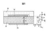
- FIG. 5 is a diagram illustrating an example of a specific circuit constituting the voltage application device and the current detection device.
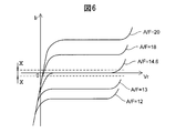
- FIG. 6 is a diagram showing the relationship between the sensor applied voltage and the output current at each exhaust air-fuel ratio.
- FIG. 7 is a diagram showing the relationship between the exhaust air-fuel ratio and the output current at each sensor applied voltage.
- FIG. 8 is an enlarged view of the area indicated by XX in FIG. FIG.
- FIG. 9 is an enlarged view of the area indicated by Y in FIG.
- FIG. 10 is a diagram showing the relationship between the sensor applied voltage and the output current of the air-fuel ratio sensor.
- FIG. 11 is a diagram showing the relationship between the exhaust air-fuel ratio and the output current in the air-fuel ratio sensor.
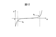
- FIG. 12 is a diagram showing the relationship between the sensor applied voltage and the output current.
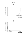
- FIG. 13 shows the relationship between the oxygen storage amount of the exhaust purification catalyst and the concentrations of NOx and unburned gas in the exhaust gas flowing out from the exhaust purification catalyst.
- FIG. 14 is a time chart of the oxygen storage amount of the exhaust purification catalyst.
- FIG. 15 is a time chart of the oxygen storage amount of the exhaust purification catalyst.
- FIG. 16 is a functional block diagram of the control device.
- FIG. 17 is a flowchart showing a control routine for calculation control of the air-fuel ratio correction amount.
- FIG. 18 is a time chart of the oxygen storage amount of the exhaust purification catalyst.
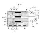
- FIG. 19 is a schematic cross-sectional view of the air-fuel ratio sensor of the second embodiment.
- FIG. 20 is a diagram schematically showing the operation of the air-fuel ratio sensor of the second embodiment.
- FIG. 1 is a diagram schematically showing an internal combustion engine in which a control device according to a first embodiment of the present invention is used.
- 1 is an engine body
- 2 is a cylinder block
- 3 is a piston that reciprocates within the cylinder block
- 4 is a cylinder head fixed on the cylinder block 2
- 5 is a piston
- 6 is an intake valve
- 7 is an intake port
- 8 is an exhaust valve
- 9 is an exhaust port.
- the intake valve 6 opens and closes the intake port 7, and the exhaust valve 8 opens and closes the exhaust port 9.
- a spark plug 10 is disposed at the center of the inner wall surface of the cylinder head 4, and a fuel injection valve 11 is disposed around the inner wall surface of the cylinder head 4.
- the spark plug 10 is configured to generate a spark in response to the ignition signal.
- the fuel injection valve 11 injects a predetermined amount of fuel into the combustion chamber 5 according to the injection signal.
- the fuel injection valve 11 may be arranged so as to inject fuel into the intake port 7.
- gasoline having a theoretical air-fuel ratio of 14.6 in the exhaust purification catalyst is used as the fuel.
- the internal combustion engine of the present invention may use other fuels.
- the intake port 7 of each cylinder is connected to a surge tank 14 via a corresponding intake branch pipe 13, and the surge tank 14 is connected to an air cleaner 16 via an intake pipe 15.
- the intake port 7, the intake branch pipe 13, the surge tank 14, and the intake pipe 15 form an intake passage.
- a throttle valve 18 driven by a throttle valve drive actuator 17 is disposed in the intake pipe 15. The throttle valve 18 is rotated by a throttle valve drive actuator 17 so that the opening area of the intake passage can be changed.
- the exhaust port 9 of each cylinder is connected to an exhaust manifold 19.
- the exhaust manifold 19 has a plurality of branches connected to the exhaust ports 9 and a collective part in which these branches are assembled.
- a collecting portion of the exhaust manifold 19 is connected to an upstream casing 21 containing an upstream exhaust purification catalyst 20.
- the upstream casing 21 is connected to a downstream casing 23 containing a downstream exhaust purification catalyst 24 via an exhaust pipe 22.
- the exhaust port 9, the exhaust manifold 19, the upstream casing 21, the exhaust pipe 22, and the downstream casing 23 form an exhaust passage.
- An electronic control unit (ECU) 31 comprises a digital computer, and is connected to each other via a bidirectional bus 32, a RAM (Random Access Memory) 33, a ROM (Read Only Memory) 34, a CPU (Microprocessor) 35, and an input.
- a port 36 and an output port 37 are provided.
- An air flow meter 39 for detecting the flow rate of air flowing through the intake pipe 15 is disposed in the intake pipe 15, and the output of the air flow meter 39 is input to the input port 36 via the corresponding AD converter 38.
- an upstream air-fuel ratio sensor 40 that detects the air-fuel ratio of the exhaust gas flowing through the exhaust manifold 19 (that is, the exhaust gas flowing into the upstream exhaust purification catalyst 20) is disposed at the collecting portion of the exhaust manifold 19.
- the downstream side that detects the air-fuel ratio of the exhaust gas that flows in the exhaust pipe 22 (that is, the exhaust gas that flows out of the upstream side exhaust purification catalyst 20 and flows into the downstream side exhaust purification catalyst 24).
- An air-fuel ratio sensor 41 is arranged. The outputs of these air-fuel ratio sensors 40 and 41 are also input to the input port 36 via the corresponding AD converter 38. The configuration of these air-fuel ratio sensors 40 and 41 will be described later.
- a load sensor 43 that generates an output voltage proportional to the amount of depression of the accelerator pedal 42 is connected to the accelerator pedal 42, and the output voltage of the load sensor 43 is input to the input port 36 via the corresponding AD converter 38.
- the crank angle sensor 44 generates an output pulse every time the crankshaft rotates 15 degrees, and this output pulse is input to the input port 36.
- the CPU 35 calculates the engine speed from the output pulse of the crank angle sensor 44.
- the output port 37 is connected to the spark plug 10, the fuel injection valve 11, and the throttle valve drive actuator 17 via the corresponding drive circuit 45.
- the ECU 31 functions as an engine control device that controls the internal combustion engine based on outputs from various sensors and the like.
- FIG. 3 is a schematic cross-sectional view of the air-fuel ratio sensors 40 and 41.
- the air-fuel ratio sensors 40 and 41 in this embodiment are one-cell type air-fuel ratio sensors each having one cell composed of a solid electrolyte layer and a pair of electrodes.
- the air-fuel ratio sensors 40 and 41 include a solid electrolyte layer 51, an exhaust-side electrode (first electrode) 52 disposed on one side surface of the solid electrolyte layer 51, and the solid electrolyte layer 51.
- An atmosphere-side electrode (second electrode) 53 disposed on the other side surface, a diffusion-controlling layer 54 that controls the diffusion of exhaust gas that passes through, a protective layer 55 that protects the diffusion-controlling layer 54, and an air-fuel ratio sensor And a heater unit 56 for heating 40 and 41.
- a diffusion-controlling layer 54 is provided on one side surface of the solid electrolyte layer 51, and a protective layer 55 is provided on the side surface of the diffusion-controlling layer 54 opposite to the side surface on the solid electrolyte layer 51 side.
- a measured gas chamber 57 is formed between the solid electrolyte layer 51 and the diffusion-controlling layer 54.
- a gas to be detected by the air-fuel ratio sensors 40, 41, that is, exhaust gas, is introduced into the measured gas chamber 57 through the diffusion rate controlling layer 54.
- the exhaust side electrode 52 is disposed in the measured gas chamber 57, and therefore, the exhaust side electrode 52 is exposed to the exhaust gas through the diffusion rate controlling layer 54.
- the gas chamber 57 to be measured is not necessarily provided, and may be configured such that the diffusion-controlling layer 54 is in direct contact with the surface of the exhaust-side electrode 52.
- a heater portion 56 is provided on the other side surface of the solid electrolyte layer 51.
- a reference gas chamber 58 is formed between the solid electrolyte layer 51 and the heater portion 56, and the reference gas is introduced into the reference gas chamber 58.
- the reference gas chamber 58 is open to the atmosphere, and therefore the atmosphere is introduced into the reference gas chamber 58 as the reference gas.
- the atmosphere side electrode 53 is disposed in the reference gas chamber 58, and therefore, the atmosphere side electrode 53 is exposed to the reference gas (reference atmosphere). In the present embodiment, since the atmosphere is used as the reference gas, the atmosphere side electrode 53 is exposed to the atmosphere.
- the heater unit 56 is provided with a plurality of heaters 59, and the heaters 59 can control the temperature of the air-fuel ratio sensors 40 and 41, particularly the temperature of the solid electrolyte layer 51.
- the heater unit 56 has a heat generation capacity sufficient to heat the solid electrolyte layer 51 until it is activated.
- the solid electrolyte layer 51 is an oxygen ion conductive oxide in which ZrO 2 (zirconia), HfO 2 , ThO 2 , Bi 2 O 3, etc. are distributed with CaO, MgO, Y 2 O 3 , Yb 2 O 3, etc. as stabilizers.
- the sintered body is formed.
- the diffusion control layer 54 is formed of a porous sintered body of a heat-resistant inorganic substance such as alumina, magnesia, silica, spinel, mullite or the like.
- the exhaust-side electrode 52 and the atmosphere-side electrode 53 are formed of a noble metal having high catalytic activity such as platinum.
- a sensor application voltage Vr is applied between the exhaust side electrode 52 and the atmosphere side electrode 53 by the voltage application device 60 mounted on the ECU 31.
- the ECU 31 is provided with a current detection device 61 that detects a current flowing between the electrodes 52 and 53 via the solid electrolyte layer 51 when the sensor application voltage Vr is applied by the voltage application device 60.
- the current detected by the current detector 61 is the output current of the air-fuel ratio sensors 40 and 41.
- FIG. 4 is a diagram schematically showing the operation of the air-fuel ratio sensors 40 and 41.
- the air-fuel ratio sensors 40 and 41 are arranged so that the outer peripheral surfaces of the protective layer 55 and the diffusion-controlling layer 54 are exposed to the exhaust gas. Air is introduced into the reference gas chamber 58 of the air-fuel ratio sensors 40 and 41.
- the solid electrolyte layer 51 is formed of a sintered body of an oxygen ion conductive oxide. Therefore, when a difference in oxygen concentration occurs between both side surfaces of the solid electrolyte layer 51 in a state activated by high temperature, an electromotive force E that attempts to move oxygen ions from the high concentration side surface to the low concentration side surface. Has a property (oxygen battery characteristics).
- oxygen ions move so that an oxygen concentration ratio is generated between both side surfaces of the solid electrolyte layer according to the potential difference.
- Characteristics oxygen pump characteristics. Specifically, when a potential difference is applied between both side surfaces, the oxygen concentration on the side surface provided with positive polarity is a ratio corresponding to the potential difference with respect to the oxygen concentration on the side surface provided with negative polarity. The movement of oxygen ions is caused to increase. Further, as shown in FIGS. 3 and 4, in the air-fuel ratio sensors 40 and 41, there is a constant gap between these electrodes 52 and 53 so that the atmosphere side electrode 53 is positive and the exhaust side electrode 52 is negative. A sensor applied voltage Vr is applied.
- the ratio of oxygen concentration between both side surfaces of the solid electrolyte layer 51 is not so large.
- the sensor applied voltage Vr is set to an appropriate value, the actual oxygen concentration ratio becomes smaller between the both side surfaces of the solid electrolyte layer 51 than the oxygen concentration ratio corresponding to the sensor applied voltage Vr. Therefore, as shown in FIG. 4A, the oxygen concentration ratio between the both side surfaces of the solid electrolyte layer 51 increases from the exhaust side electrode 52 to the atmosphere so as to increase toward the oxygen concentration ratio corresponding to the sensor applied voltage Vr. Oxygen ions move toward the side electrode 53. As a result, a current flows from the positive electrode of the voltage application device 60 that applies the sensor application voltage Vr to the negative electrode of the voltage application device 60 via the atmosphere side electrode 53, the solid electrolyte layer 51, and the exhaust side electrode 52.
- the magnitude of the current (output current) Ir flowing at this time is the amount of oxygen flowing into the measured gas chamber 57 from the exhaust gas through the diffusion rate controlling layer 54 if the sensor applied voltage Vr is set to an appropriate value. Is proportional to Therefore, by detecting the magnitude of the current Ir by the current detector 61, it is possible to know the oxygen concentration and thus the air-fuel ratio in the lean region.
- the exhaust gas is exhausted from the atmosphere side electrode 53 so that the oxygen concentration ratio between the both side surfaces of the solid electrolyte layer 51 decreases toward the oxygen concentration ratio corresponding to the sensor applied voltage Vr.
- Oxygen ions move toward the side electrode 52.
- a current flows from the atmosphere side electrode 53 to the exhaust side electrode 52 through the voltage application device 60 that applies the sensor application voltage Vr.
- the magnitude of the current (output current) Ir flowing at this time is that of oxygen ions that can be moved from the atmosphere side electrode 53 to the exhaust side electrode 52 in the solid electrolyte layer 51 if the sensor applied voltage Vr is set to an appropriate value. It depends on the flow rate.
- the oxygen ions react (combust) on the exhaust-side electrode 52 with the unburned gas that flows into the measured gas chamber 57 from the exhaust gas through the diffusion-controlling layer 54 by diffusion. Therefore, the moving flow rate of oxygen ions corresponds to the concentration of unburned gas in the exhaust gas flowing into the measured gas chamber 57. Therefore, by detecting the magnitude of the current Ir by the current detection device 61, it is possible to know the unburned gas concentration and thus the air-fuel ratio in the rich region.
- the exhaust air-fuel ratio around the air-fuel ratio sensors 40, 41 is the stoichiometric air-fuel ratio
- the amount of oxygen and unburned gas flowing into the measured gas chamber 57 is the chemical equivalent ratio.
- both of them are completely combusted by the catalytic action of the exhaust side electrode 52, and the concentration of oxygen and unburned gas in the measured gas chamber 57 does not change.
- the oxygen concentration ratio between the both side surfaces of the solid electrolyte layer 51 is not changed and is maintained as the oxygen concentration ratio corresponding to the sensor applied voltage Vr.
- FIG. 4C oxygen ions do not move due to the oxygen pump characteristics, and as a result, no current flows through the circuit.
- FIG. 5 shows an example of a specific circuit constituting the voltage application device 60 and the current detection device 61.
- E is an electromotive force generated by oxygen battery characteristics
- Ri is an internal resistance of the solid electrolyte layer 51
- Vs is a potential difference between the electrodes 52 and 53.
- the voltage application device 60 basically performs negative feedback control so that the electromotive force E generated by the oxygen battery characteristics matches the sensor applied voltage Vr.
- the voltage application device 60 becomes the sensor applied voltage Vr. Negative feedback control is performed.
- the oxygen concentration ratio between the both side surfaces of the solid electrolyte layer 51 is determined by sensor application.
- the oxygen concentration ratio corresponds to the voltage Vr.
- the electromotive force E coincides with the sensor applied voltage Vr, and the potential difference Vs between the electrodes 52 and 53 is also the sensor applied voltage Vr. As a result, the current Ir does not flow.
- the electromotive force E has a value different from the sensor applied voltage Vr. Therefore, by negative feedback control, a potential difference Vs is applied between the electrodes 52 and 53 in order to move oxygen ions between both side surfaces of the solid electrolyte layer 51 so that the electromotive force E matches the sensor applied voltage Vr. The And current Ir flows with the movement of oxygen ions at this time. As a result, the electromotive force E converges on the sensor applied voltage Vr, and when the electromotive force E converges on the sensor applied voltage Vr, the potential difference Vs eventually converges on the sensor applied voltage Vr.
- the voltage application device 60 substantially applies the sensor application voltage Vr between the electrodes 52 and 53.
- the electric circuit of the voltage applying device 60 is not necessarily as shown in FIG. 5, and any device can be used as long as the sensor applied voltage Vr can be substantially applied between the electrodes 52 and 53. It may be.
- the current detector 61 is actually a current rather than detecting, and calculates the current from the voltage E 0 by detecting the voltage E 0.
- E 0 can be expressed as the following formula (1).
- E 0 Vr + V 0 + IrR (1)
- V 0 is an offset voltage (a voltage applied so that E 0 does not become a negative value, for example, 3 V)
- R is the value of the resistance shown in FIG.
- the sensor applied voltage Vr, the offset voltage V 0 and the resistance value R are constant, so that the voltage E 0 changes according to the current Ir. Therefore, if the voltage E 0 is detected, the current Ir can be calculated from the voltage E 0 .
- the current detection device 61 substantially detects the current Ir flowing between the electrodes 52 and 53.
- the electric circuit of the current detection device 61 does not necessarily have to be as shown in FIG. 5, and any device can be used as long as the current Ir flowing between the electrodes 52 and 53 can be detected. Good.
- the air-fuel ratio sensors 40 and 41 configured and operated as described above have voltage-current (VI) characteristics as shown in FIG. As can be seen from FIG. 6, when the sensor applied voltage Vr is gradually increased from a negative value when the exhaust air-fuel ratio is constant in the region where the sensor applied voltage Vr is 0 or less and in the vicinity of 0, As a result, the output current Ir increases.
- Vr voltage-current
- the flow rate of oxygen ions that can move through the solid electrolyte layer 51 is small. For this reason, the flow rate of oxygen ions that can move through the solid electrolyte layer 51 is smaller than the inflow rate of the exhaust gas through the diffusion-controlling layer 54, so that the output current Ir can move through the solid electrolyte layer 51. It changes according to the flow rate of oxygen ions. Since the flow rate of oxygen ions that can move through the solid electrolyte layer 51 changes according to the sensor applied voltage Vr, the output current increases as the sensor applied voltage Vr increases. The voltage region in which the output current Ir changes in proportion to the sensor applied voltage Vr is referred to as a proportional region. The reason why the output current Ir takes a negative value when the sensor applied voltage Vr is 0 is that an electromotive force E corresponding to the oxygen concentration ratio between both side surfaces of the solid electrolyte layer 51 is generated due to the oxygen battery characteristics.
- the output current Ir changes according to the oxygen concentration or the unburned gas concentration in the exhaust gas flowing into the measured gas chamber 57 via the diffusion rate controlling layer 54. Even if the sensor applied voltage Vr is changed with the exhaust air-fuel ratio being constant, the oxygen concentration and the unburned gas concentration in the exhaust gas flowing into the measured gas chamber 57 via the diffusion-controlling layer 54 should basically not change. Therefore, the output voltage Ir does not change.
- the output current Ir depends on the exhaust air / fuel ratio. Change. As can be seen from FIG. 6, the flow direction of the limit current is reversed between the lean air-fuel ratio and the rich air-fuel ratio, and the air-fuel ratio increases as the lean air-fuel ratio increases, and the air-fuel ratio decreases as the rich air-fuel ratio increases. The absolute value of the limit current increases.
- the output current Ir begins to increase again accordingly.
- the moisture contained in the exhaust gas is decomposed on the exhaust-side electrode 52, and a current flows accordingly.
- the sensor applied voltage Vr is further increased, the current cannot be provided only by the decomposition of water, and the decomposition of the solid electrolyte layer 51 occurs this time.
- a voltage region in which water and solid electrolyte layer 51 are decomposed in this way is referred to as a water decomposition region.
- FIG. 7 is a diagram showing the relationship between the exhaust air-fuel ratio and the output current Ir at each sensor applied voltage Vr.
- the output current Ir changes according to the exhaust air-fuel ratio at least in the vicinity of the theoretical air-fuel ratio.
- the sensor applied voltage Vr is about 0.1 V to 0.9 V
- the relationship between the exhaust air-fuel ratio and the output current Ir near the theoretical air-fuel ratio is the sensor applied voltage Vr. It is almost the same regardless of it.
- the output current Ir hardly changes even if the exhaust air-fuel ratio changes.
- This constant exhaust air-fuel ratio also changes according to the sensor applied voltage Vr, and is lower as the sensor applied voltage Vr is lower. For this reason, when the sensor applied voltage Vr is lowered to a certain value or less, the output current Ir does not become zero regardless of the exhaust air / fuel ratio, as indicated by a two-dot chain line in the figure ( For example, when the sensor applied voltage Vr is 0 V, the output current Ir does not become 0 regardless of the exhaust air-fuel ratio).
- FIG. 8 is an enlarged view of a region (region indicated by XX in FIG. 6) in which the output current Ir is close to 0 in the voltage-current diagram of FIG.
- the output current Ir also increases slightly as the sensor applied voltage Vr increases.
- the sensor applied voltage Vr is somewhat lower than 0.45 V (for example, 0.2 V)
- the output current becomes a value lower than 0.
- the sensor applied voltage Vr is somewhat higher than 0.45 V (for example, 0.7 V)
- the output current becomes a value higher than 0.
- FIG. 9 is an enlarged view of the region where the exhaust air-fuel ratio is close to the theoretical air-fuel ratio and the output current Ir is close to 0 (the region indicated by Y in FIG. 7) in the air-fuel ratio-current diagram of FIG. FIG. FIG. 9 shows that in the region near the theoretical air-fuel ratio, the output current Ir for the same exhaust air-fuel ratio is slightly different for each sensor applied voltage Vr.
- the output current Ir becomes 0 when the sensor applied voltage Vr is 0.45 V.
- the output current Ir increases.
- the sensor application voltage Vr is less than 0.45V, the output current Ir also decreases.
- FIG. 9 shows that the exhaust air / fuel ratio when the output current Ir becomes 0 (hereinafter referred to as “exhaust air / fuel ratio at zero current”) differs for each sensor applied voltage Vr.
- the output current Ir becomes 0 when the exhaust air-fuel ratio is the stoichiometric air-fuel ratio.
- the sensor applied voltage Vr is larger than 0.45 V, the output current Ir becomes 0 when the exhaust air-fuel ratio is richer than the stoichiometric air-fuel ratio, and the current increases as the sensor applied voltage Vr increases.
- the exhaust air-fuel ratio at zero becomes smaller.
- the output current Ir becomes 0 when the exhaust air-fuel ratio is leaner than the stoichiometric air-fuel ratio, and when the sensor applied voltage Vr becomes smaller, the current becomes zero.
- the exhaust air / fuel ratio increases. That is, by changing the sensor applied voltage Vr, the exhaust air-fuel ratio at the time of zero current can be changed.
- the output current change rate varies among the individual air-fuel ratio sensors, or even the same air-fuel ratio sensor varies due to deterioration over time.
- the exhaust air-fuel ratio at zero current the stoichiometric air-fuel ratio in the example of FIG. 2 hardly changes. That is, when the output current Ir takes a value other than zero, it is difficult to accurately detect the absolute value of the exhaust air-fuel ratio, whereas when the output current Ir becomes zero, the absolute value of the exhaust air-fuel ratio. (The theoretical air-fuel ratio in the example of FIG. 2) can be accurately detected.
- the air-fuel ratio sensors 40 and 41 can change the exhaust air-fuel ratio at zero current by changing the sensor applied voltage Vr. That is, if the sensor applied voltage Vr is set appropriately, the absolute value of the exhaust air / fuel ratio other than the stoichiometric air / fuel ratio can be accurately detected. In particular, when the sensor applied voltage Vr is changed within a “specific voltage range” to be described later, the exhaust air / fuel ratio at zero current is only slightly (for example, ⁇ 1) with respect to the theoretical air / fuel ratio (14.6). % Range (within about 14.45 to about 14.75) can be adjusted. Therefore, by appropriately setting the sensor applied voltage Vr, it becomes possible to accurately detect the absolute value of the air-fuel ratio slightly different from the theoretical air-fuel ratio.
- the exhaust air-fuel ratio at the time of zero current can be changed by changing the sensor applied voltage Vr.
- the sensor applied voltage Vr is made larger than a certain upper limit voltage or made smaller than a certain lower limit voltage, the amount of change in the exhaust air / fuel ratio at zero current with respect to the amount of change in the sensor applied voltage Vr becomes larger. Therefore, in such a voltage region, if the sensor applied voltage Vr slightly shifts, the exhaust air-fuel ratio at the time of zero current changes greatly. Therefore, in such a voltage region, in order to accurately detect the absolute value of the exhaust air / fuel ratio, it is necessary to precisely control the sensor applied voltage Vr, which is not practical. For this reason, from the viewpoint of accurately detecting the absolute value of the exhaust air-fuel ratio, the sensor applied voltage Vr needs to be a value within a “specific voltage region” between a certain upper limit voltage and a certain lower limit voltage. Become.
- Such a specific voltage region can be defined in various ways. Hereinafter, some examples of definitions will be described with reference to FIGS.
- the air-fuel ratio sensors 40 and 41 are in a voltage region where the output current Ir increases as the sensor applied voltage Vr increases for each exhaust air-fuel ratio.
- There is a certain current increasing region and a current slightly increasing region which is a voltage region in which the increase amount of the output current Ir with respect to the increasing amount of the sensor applied voltage Vr is smaller than the current increasing region due to the provision of the diffusion rate limiting layer (FIG. 10 ( A) shows the current increasing region and the current slightly increasing region only when the exhaust air-fuel ratio is the stoichiometric air-fuel ratio).
- the current slightly increasing region when the exhaust air-fuel ratio is the stoichiometric air-fuel ratio is set as the “specific voltage region”.
- the air-fuel ratio sensors 40 and 41 each have a limit current region that is a voltage region in which the output current Ir becomes a limit current for each exhaust air-fuel ratio ( FIG. 10B shows the limit current region only when the exhaust air-fuel ratio is the stoichiometric air-fuel ratio.
- the limit current region when the exhaust air-fuel ratio is the stoichiometric air-fuel ratio is set as the “specific voltage region”.
- the air-fuel ratio sensors 40 and 41 are proportional to each other in the voltage region where the output current increases in proportion to the increase in applied voltage for each exhaust air-fuel ratio.
- An area a water decomposition area that is a voltage area in which an output current changes in accordance with a change in applied voltage due to the decomposition of water or the solid electrolyte layer 51, and a voltage area between the proportional area and the water decomposition area (In FIG. 10C, the proportional region, the water splitting region, and the intermediate region are shown only when the exhaust air-fuel ratio is the stoichiometric air-fuel ratio).
- the intermediate region when the exhaust air-fuel ratio is the stoichiometric air-fuel ratio is set as the “specific voltage region”.
- the exhaust air / fuel ratio at zero current varies according to the sensor applied voltage Vr, and the exhaust air / fuel ratio at zero current decreases as the sensor applied voltage Vr increases.
- the exhaust air-fuel ratio at the time of zero current is 0.5, for example, higher than the theoretical air-fuel ratio AFst.
- the air-fuel ratio is low by about 2% (preferably about 1%).
- the exhaust air-fuel ratio at the time of zero current becomes an air-fuel ratio that is, for example, about 0.5 to 2% (preferably about 1%) higher than the theoretical air-fuel ratio AFst.
- the upper limit voltage value the voltage value at which the exhaust air-fuel ratio at zero current is 1% lower than the stoichiometric air-fuel ratio AFst, for example
- the lower limit voltage value exhaust air-fuel ratio at zero current. Is a voltage range between the stoichiometric air-fuel ratio AFst, for example, a voltage value that is 1% higher than the stoichiometric air-fuel ratio AFst).
- FIG. 12 shows changes in current with respect to voltage.
- the output current reaches the first inflection point B 1 as the sensor applied voltage Vr increases from the negative state for each exhaust air-fuel ratio.
- the output current Ir increases from the first inflection point B 1 to the second inflection point B 2 as the sensor application voltage Vr increases, and as the sensor application voltage Vr increases from the second inflection point.
- the output current Ir increases.
- the increase amount of the applied current Ir with respect to the increase amount of the sensor applied voltage Vr is smaller than in the other voltage regions.
- the voltage between the first inflection point and the second inflection point when the exhaust air-fuel ratio is the stoichiometric air-fuel ratio is set as the “specific voltage region”.
- the upper limit voltage value and the lower limit voltage value of the “specific voltage region” are specified by specific numerical values.
- the “specific voltage region” is 0.05 V or more and 0.95 V or less, preferably 0.1 V or more and 0.9 V or less, more preferably 0.15 V or more and 0.8 V or less.
- the exhaust air-fuel ratio becomes any value as shown by the one-dot chain line in the figure. Even if it exists, the output current Ir does not become zero.
- the sensor applied voltage Vr is lowered below a certain value (minimum voltage)
- the output current Ir becomes 0 regardless of the exhaust air / fuel ratio, as indicated by the two-dot chain line in the figure. No longer.
- the sensor applied voltage Vr is a voltage between the maximum voltage and the minimum voltage, an exhaust air-fuel ratio where the output current becomes zero exists. Conversely, if the sensor applied voltage Vr is higher than the maximum voltage or lower than the minimum voltage, there is no exhaust air / fuel ratio at which the output current becomes zero. Therefore, the sensor applied voltage Vr is at least a voltage at which the output current becomes zero when the exhaust air-fuel ratio is any air-fuel ratio, that is, a voltage between the maximum voltage and the minimum voltage. I need it.
- the above-described “specific voltage region” is a voltage region between the maximum voltage and the minimum voltage.
- the sensor applied voltage Vrupp in the upstream air-fuel ratio sensor 40 is theoretically the exhaust air-fuel ratio. It is fixed at a constant voltage (for example, 0.45 V) such that the output current becomes zero when the air-fuel ratio is 14.6 in this embodiment.
- the sensor applied voltage Vrup is set so that the exhaust air-fuel ratio at zero current becomes the stoichiometric air-fuel ratio.
- the sensor applied voltage Vr in the downstream air-fuel ratio sensor 41 is determined in advance so that the exhaust air-fuel ratio is slightly richer than the stoichiometric air-fuel ratio. It is fixed at a constant voltage (for example, 0.7 V) such that the output current becomes zero when the air-fuel ratio is a predetermined value (for example, 14.55, hereinafter referred to as “rich determination air-fuel ratio”).
- the sensor applied voltage Vrdwn is set so that the exhaust air-fuel ratio at the time of zero current becomes a rich determination air-fuel ratio that is slightly richer than the theoretical air-fuel ratio.
- the sensor applied voltage Vrdwn in the downstream air-fuel ratio sensor 41 is set to a voltage higher than the sensor applied voltage Vrup in the upstream air-fuel ratio sensor 40.
- the ECU 31 connected to both the air-fuel ratio sensors 40 and 41 has the stoichiometric air-fuel ratio around the upstream air-fuel ratio sensor 40 when the output current Irup of the upstream air-fuel ratio sensor 40 becomes zero.
- the ECU 31 determines that the exhaust air-fuel ratio around the downstream air-fuel ratio sensor 41 is different from the rich determination air-fuel ratio, that is, the stoichiometric air-fuel ratio. Judge that the air-fuel ratio.
- the air-fuel ratio of the exhaust gas is detected by the air-fuel ratio sensor, for example, when fuel cut control described later is not executed, or the air-fuel ratio detected by the air-fuel ratio sensor becomes a high value of 18 or more. When not.
- the upstream side exhaust purification catalyst 20 is a three-way catalyst having an oxygen storage capacity. Specifically, the upstream side exhaust purification catalyst 20 supports a noble metal having a catalytic action (for example, platinum (Pt)) and a substance having an oxygen storage capacity (for example, ceria (CeO 2 )) on a carrier made of ceramic. It has been made. When the upstream exhaust purification catalyst 20 reaches a predetermined activation temperature, the upstream exhaust purification catalyst 20 exhibits oxygen storage capacity in addition to the catalytic action of simultaneously purifying unburned gas (HC, CO, etc.) and nitrogen oxides (NOx).
- HC, CO, etc. hydrogen oxides
- the upstream side exhaust purification catalyst 20 is such that the air-fuel ratio of the exhaust gas flowing into the upstream side exhaust purification catalyst 20 is leaner than the stoichiometric air-fuel ratio (lean air-fuel ratio). Sometimes it stores oxygen in the exhaust gas. On the other hand, the upstream side exhaust purification catalyst 20 releases oxygen stored in the upstream side exhaust purification catalyst 20 when the air-fuel ratio of the inflowing exhaust gas is richer than the stoichiometric air-fuel ratio (rich air-fuel ratio).
- the “air-fuel ratio of exhaust gas” means the ratio of the mass of fuel to the mass of air supplied until the exhaust gas is generated. Normally, combustion is performed when the exhaust gas is generated. It means the ratio of the mass of fuel to the mass of air supplied into the chamber 5.
- the upstream side exhaust purification catalyst 20 has a catalytic action and an oxygen storage capacity, and thus has a NOx and unburned gas purification action according to the oxygen storage amount.
- FIG. 13 shows the relationship between the oxygen storage amount of the upstream side exhaust purification catalyst 20 and the concentrations of NOx and unburned gas (HC, CO, etc.) in the exhaust gas flowing out from the upstream side exhaust purification catalyst 20.
- FIG. 13A shows the oxygen storage amount and the NOx concentration in the exhaust gas flowing out from the upstream side exhaust purification catalyst 20 when the air-fuel ratio of the exhaust gas flowing into the upstream side exhaust purification catalyst 20 is a lean air-fuel ratio. The relationship is shown.
- FIG. 13 shows the relationship between the oxygen storage amount of the upstream side exhaust purification catalyst 20 and the concentrations of NOx and unburned gas (HC, CO, etc.) in the exhaust gas flowing out from the upstream side exhaust purification catalyst 20.
- FIG. 13A shows the oxygen storage amount and the NOx concentration in the exhaust
- 13B shows the oxygen storage amount and the unexhausted amount of exhaust gas flowing out from the upstream side exhaust purification catalyst 20 when the air-fuel ratio of the exhaust gas flowing into the upstream side exhaust purification catalyst 20 is a rich air-fuel ratio. The relationship with the concentration of fuel gas is shown.
- the air-fuel ratio of the exhaust gas flowing into the upstream side exhaust purification catalyst 20 is a rich air-fuel ratio (that is, the exhaust gas does not contain unburned gas such as HC and CO).
- the oxygen stored in the upstream side exhaust purification catalyst 20 is released.
- the unburned gas in the exhaust gas flowing into the upstream side exhaust purification catalyst 20 is oxidized and purified.
- the exhaust gas flowing out from the upstream side exhaust purification catalyst 20 contains almost no unburned gas.
- the exhaust purification catalysts 20 and 24 used in the present embodiment NOx and unburned gas in the exhaust gas according to the air-fuel ratio and oxygen storage amount of the exhaust gas flowing into the exhaust purification catalysts 20 and 24.
- the exhaust purification catalysts 20 and 24 may be different from the three-way catalyst as long as they have a catalytic action and an oxygen storage capacity.
- the target air-fuel ratio of the exhaust gas flowing into the upstream side exhaust purification catalyst 20 is set based on the output current Irdwn of the downstream side air-fuel ratio sensor 41. Specifically, when the output current Irdwn of the downstream side air-fuel ratio sensor 41 becomes zero or less, the target air-fuel ratio is set to the lean set air-fuel ratio and is maintained at that air-fuel ratio. When the output current Irdwn becomes zero or less, the air-fuel ratio of the exhaust gas flowing out from the upstream side exhaust purification catalyst 20 is slightly richer than the stoichiometric air-fuel ratio. 55) Means the following.
- the lean set air-fuel ratio is a predetermined air-fuel ratio that is somewhat leaner than the stoichiometric air-fuel ratio, and is, for example, 14.65 to 20, preferably 14.68 to 18, and more preferably 14.7. About 16 or so.
- the oxygen storage amount OSAsc of the upstream side exhaust purification catalyst 20 is estimated.
- the oxygen storage amount OSAsc is estimated by estimating the intake air amount into the combustion chamber 5 calculated based on the output current Irup of the upstream air-fuel ratio sensor 40 and the air flow meter 39 or the like, or fuel injection from the fuel injection valve 11. It is performed based on the quantity.
- the estimated value of the oxygen storage amount OSAsc becomes equal to or larger than a predetermined determination reference storage amount Cref, the target air-fuel ratio that has been the lean set air-fuel ratio until then becomes the weak rich set air-fuel ratio, and is maintained at that air-fuel ratio.
- the The weak rich set air-fuel ratio is a predetermined air-fuel ratio that is slightly richer than the stoichiometric air-fuel ratio, and is, for example, 13.5 to 14.58, preferably 14 to 14.57, more preferably 14.3. About 14.55. Thereafter, when the output current Irdwn of the downstream side air-fuel ratio sensor 41 becomes zero or less again, the target air-fuel ratio is made the lean set air-fuel ratio again, and then the same operation is repeated.
- the target air-fuel ratio of the exhaust gas flowing into the upstream side exhaust purification catalyst 20 is alternately set to the lean set air-fuel ratio and the weak rich set air-fuel ratio.
- the difference between the lean set air-fuel ratio and the stoichiometric air-fuel ratio is larger than the difference between the weak rich set air-fuel ratio and the stoichiometric air-fuel ratio. Therefore, in this embodiment, the target air-fuel ratio is alternately set to a short-term lean set air-fuel ratio and a long-term weak rich set air-fuel ratio.
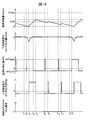
- FIG. 14 shows the oxygen storage amount OSAsc of the upstream side exhaust purification catalyst 20, the output current Irdwn of the downstream side air-fuel ratio sensor 41, and the air-fuel ratio correction amount AFC when air-fuel ratio control is performed in the control apparatus for an internal combustion engine of the present invention.
- 4 is a time chart of the output current Irup of the upstream air-fuel ratio sensor 40 and the NOx concentration in the exhaust gas flowing out from the upstream side exhaust purification catalyst 20.
- the output current Irup of the upstream air-fuel ratio sensor 40 becomes zero when the air-fuel ratio of the exhaust gas flowing into the upstream side exhaust purification catalyst 20 is the stoichiometric air-fuel ratio, and the exhaust gas empty A negative value is obtained when the fuel ratio is a rich air-fuel ratio, and a positive value is obtained when the air-fuel ratio of the exhaust gas is a lean air-fuel ratio.
- the absolute value of the output current Irup of the upstream air-fuel ratio sensor 40 increases as the difference from the stoichiometric air-fuel ratio increases. The value increases.
- the output current Irdwn of the downstream side air-fuel ratio sensor 41 becomes zero when the air-fuel ratio of the exhaust gas flowing out from the upstream side exhaust purification catalyst 20 is the rich determination air-fuel ratio (slightly richer than the theoretical air-fuel ratio).
- a negative value is obtained when the air-fuel ratio of the exhaust gas is richer than the rich determination air-fuel ratio, and a positive value is obtained when the air-fuel ratio of the exhaust gas is leaner than the rich determination air-fuel ratio.
- the output current of the downstream side air-fuel ratio sensor 41 becomes larger as the difference from the rich judgment air-fuel ratio becomes larger.
- the absolute value of Irdwn increases.
- the air / fuel ratio correction amount AFC is a correction amount related to the target air / fuel ratio.
- the target air-fuel ratio is the stoichiometric air-fuel ratio.
- the air-fuel ratio correction amount AFC is a positive value
- the target air-fuel ratio is a lean air-fuel ratio
- the air-fuel ratio correction amount AFC is a negative value. In some cases, the target air-fuel ratio becomes a rich air-fuel ratio.
- the air-fuel ratio correction amount AFC is set to the weak rich set correction amount AFCrich.
- the weak rich set correction amount AFCrich is a value corresponding to the weak rich set air-fuel ratio, and is a value smaller than zero. Accordingly, the target air-fuel ratio is set to a rich air-fuel ratio, and accordingly, the output current Irup of the upstream air-fuel ratio sensor 40 becomes a negative value. Since the exhaust gas flowing into the upstream side exhaust purification catalyst 20 contains unburned gas, the oxygen storage amount OSAsc of the upstream side exhaust purification catalyst 20 gradually decreases.
- the unburned gas contained in the exhaust gas is purified by the upstream side exhaust purification catalyst 20, and the air-fuel ratio of the exhaust gas flowing out from the upstream side exhaust purification catalyst 20 becomes substantially the stoichiometric air-fuel ratio. For this reason, the output current Irdwn of the downstream side air-fuel ratio sensor becomes a positive value (corresponding to the theoretical air-fuel ratio). At this time, since the air-fuel ratio of the exhaust gas flowing into the upstream side exhaust purification catalyst 20 is a rich air-fuel ratio, the NOx emission amount from the upstream side exhaust purification catalyst 20 is suppressed.
- the oxygen storage amount OSAsc of the upstream side exhaust purification catalyst 20 gradually decreases, the oxygen storage amount OSAsc decreases beyond the lower limit storage amount (see Crowlim in FIG. 13) at time t 1 .
- the oxygen storage amount OSAsc decreases below the lower limit storage amount, a part of the unburned gas that has flowed into the upstream side exhaust purification catalyst 20 flows out without being purified by the upstream side exhaust purification catalyst 20. Therefore, after time t 1 , the output current Irdwn of the downstream air-fuel ratio sensor 41 gradually decreases as the oxygen storage amount OSAsc of the upstream side exhaust purification catalyst 20 decreases. Also at this time, since the air-fuel ratio of the exhaust gas flowing into the upstream side exhaust purification catalyst 20 is a rich air-fuel ratio, the NOx emission amount from the upstream side exhaust purification catalyst 20 is suppressed.
- the output current Irdwn of the downstream air-fuel ratio sensor 41 reaches zero corresponding to the rich determination air-fuel ratio.
- the air-fuel ratio correction amount AFC becomes the lean set correction amount AFClean so as to suppress the decrease in the oxygen storage amount OSAsc of the upstream side exhaust purification catalyst 20.
- the lean set correction amount AFClean is a value corresponding to the lean set air-fuel ratio, and is a value larger than zero. Therefore, the target air-fuel ratio is a lean air-fuel ratio.
- the air-fuel ratio correction amount AFC is switched. This is because even if the oxygen storage amount of the upstream side exhaust purification catalyst 20 is sufficient, the air-fuel ratio of the exhaust gas flowing out from the upstream side exhaust purification catalyst 20 may slightly deviate from the stoichiometric air-fuel ratio. is there.
- the rich determination air-fuel ratio is such that the air-fuel ratio of the exhaust gas flowing out from the upstream side exhaust purification catalyst 20 hardly reaches when the oxygen storage amount of the upstream side exhaust purification catalyst 20 is sufficient.
- the fuel ratio is set.
- the oxygen storage amount OSAsc of the upstream side exhaust purification catalyst 20 increases.
- the air-fuel ratio of the exhaust gas flowing out from the upstream side exhaust purification catalyst 20 changes to the stoichiometric air-fuel ratio
- the output current Irdwn of the downstream side air-fuel ratio sensor 41 is also a positive value corresponding to the stoichiometric air-fuel ratio. Converge to.
- the air-fuel ratio of the exhaust gas flowing into the upstream side exhaust purification catalyst 20 is a lean air-fuel ratio.
- the oxygen storage capacity of the upstream side exhaust purification catalyst 20 has a sufficient margin, the inflowing exhaust gas The oxygen therein is stored in the upstream side exhaust purification catalyst 20, and NOx is reduced and purified. For this reason, the NOx emission amount from the upstream side exhaust purification catalyst 20 is suppressed.
- the oxygen storage amount OSAsc the upstream exhaust purification catalyst 20 is increased, the oxygen storage amount OSAsc at time t 4 reaches the determination reference storage amount Cref.
- the air-fuel ratio correction amount AFC is set to the weak rich set correction amount AFCrich (less than 0) in order to stop storing oxygen in the upstream side exhaust purification catalyst 20. (Small value). Therefore, the target air-fuel ratio is set to a rich air-fuel ratio.
- the oxygen storage amount OSAsc is also the maximum oxygen storage amount Cmax at time t 5 .
- the upper limit occlusion amount is not reached.
- the determination reference storage amount Cref is equal to the oxygen storage amount OSAsc. The amount is sufficiently small so as not to reach the maximum oxygen storage amount Cmax or the upper limit storage amount.
- the criterion storage amount Cref is 3/4 or less, preferably 1/2 or less, more preferably 1/5 or less of the maximum oxygen storage amount Cmax. Therefore, the NOx emission amount from the upstream side exhaust purification catalyst 20 is also suppressed from time t 4 to t 5 .
- the air-fuel ratio correction amount AFC there is a weak rich set correction amount AFCrich. Accordingly, the target air-fuel ratio is set to a rich air-fuel ratio, and accordingly, the output current Irup of the upstream air-fuel ratio sensor 40 becomes a negative value. Since the exhaust gas flowing into the upstream exhaust purification catalyst 20 will include unburned gas, the oxygen storage amount OSAsc the upstream exhaust purification catalyst 20 is gradually decreased at time t 6, the time Similar to t 1 , the oxygen storage amount OSAsc decreases beyond the lower limit storage amount. Also at this time, since the air-fuel ratio of the exhaust gas flowing into the upstream side exhaust purification catalyst 20 is a rich air-fuel ratio, the NOx emission amount from the upstream side exhaust purification catalyst 20 is suppressed.
- the control of the air-fuel ratio correction amount AFC is performed by the ECU 31. Therefore, the ECU 31 determines that the oxygen storage amount OSAsc of the upstream side exhaust purification catalyst 20 is equal to the determination reference storage amount Cref when the air-fuel ratio of the exhaust gas detected by the downstream air-fuel ratio sensor 41 becomes equal to or less than the rich determination air-fuel ratio.
- the oxygen storage amount increasing means for continuously setting the target air-fuel ratio of the exhaust gas flowing into the upstream side exhaust purification catalyst 20 to the lean set air-fuel ratio and the oxygen storage amount OSAsc of the upstream side exhaust purification catalyst 20 are determined as the reference storage. When the amount Cref is equal to or greater than the amount Cref, the oxygen storage amount decreases continuously so that the target air-fuel ratio decreases toward zero without reaching the maximum oxygen storage amount Cmax. Means.
- the NOx emission amount from the upstream side exhaust purification catalyst 20 can always be suppressed. That is, as long as the above-described control is performed, the NOx emission amount from the upstream side exhaust purification catalyst 20 can be basically reduced.
- the oxygen storage amount OSAsc when the oxygen storage amount OSAsc is estimated based on the output current Irup of the upstream air-fuel ratio sensor 40, the estimated value of the intake air amount, and the like, an error may occur. Also in this embodiment, since the oxygen storage amount OSAsc is estimated from time t 3 to t 4 , the estimated value of the oxygen storage amount OSAsc includes some errors. However, even if such an error is included, if the reference storage amount Cref is set sufficiently lower than the maximum oxygen storage amount Cmax or the upper limit storage amount, the actual oxygen storage amount OSAsc will be the maximum oxygen storage amount. The amount Cmax and the upper limit storage amount are hardly reached. Therefore, the NOx emission amount from the upstream side exhaust purification catalyst 20 can be suppressed also from such a viewpoint.
- the oxygen storage amount of the exhaust purification catalyst is kept constant, the oxygen storage capacity of the exhaust purification catalyst will be reduced.
- the oxygen storage amount OSAsc constantly fluctuates up and down, it is possible to suppress a decrease in the oxygen storage capacity.
- the downstream air-fuel ratio sensor 41 can accurately detect the absolute value at the rich determination air-fuel ratio. As described with reference to FIG. 2, it is difficult for the conventional air-fuel ratio sensor to accurately detect the absolute value of the air-fuel ratio other than the stoichiometric air-fuel ratio. For this reason, if an error occurs in the output current of the conventional air-fuel ratio sensor due to deterioration over time, individual differences, etc., even if the actual air-fuel ratio of the exhaust gas is different from the rich judgment air-fuel ratio, the output current of the air-fuel ratio sensor It becomes a value corresponding to the rich determination air-fuel ratio.
- the switching timing of the air-fuel ratio correction amount AFC from the weak rich setting correction amount AFCrich to the lean setting correction amount AFClean is delayed, or such switching is performed at a timing that does not require switching.
- the downstream air-fuel ratio sensor 41 can accurately detect the absolute value at the rich determination air-fuel ratio. For this reason, it is possible to suppress a delay in the switching timing of the air-fuel ratio correction amount AFC from the weak rich setting correction amount AFCrich to the lean setting correction amount AFClean or switching at a timing that does not require switching.
- the air-fuel ratio correction amount AFC is maintained at the lean set correction amount AFClean from time t 2 to t 4 .
- the air-fuel ratio correction amount AFC does not necessarily have to be kept constant, and may be set so as to fluctuate, for example, gradually decrease.
- the air-fuel ratio correction amount AFC is maintained at the weak rich set correction amount AFrich.
- the air-fuel ratio correction amount AFC does not necessarily have to be kept constant, and may be set so as to fluctuate, for example, gradually decrease.
- the air-fuel ratio correction amount AFC at the times t 2 to t 4 is the difference between the average value of the target air-fuel ratio and the theoretical air-fuel ratio in the period, so that the target air-fuel ratio at the times t 4 to t 7 It is set to be larger than the difference between the average value of the fuel ratio and the stoichiometric air-fuel ratio.
- the oxygen storage amount OSAsc of the upstream side exhaust purification catalyst 20 is estimated based on the output current Irup of the upstream side air-fuel ratio sensor 40 and the estimated value of the intake air amount into the combustion chamber 5. Yes.
- the oxygen storage amount OSAsc may be calculated based on other parameters in addition to these parameters, or may be estimated based on parameters different from these parameters.
- the target air-fuel ratio is switched from the lean set air-fuel ratio to the slightly rich set air-fuel ratio.
- the timing at which the target air-fuel ratio is switched from the lean set air-fuel ratio to the weakly rich set air-fuel ratio is determined by other parameters such as the engine operation time after the target air-fuel ratio is switched from the weak rich set air-fuel ratio to the lean set air-fuel ratio. May be used as a reference.
- the target air-fuel ratio is changed from the lean set air-fuel ratio to the slightly rich set air-fuel ratio while the oxygen storage amount OSAsc of the upstream side exhaust purification catalyst 20 is estimated to be smaller than the maximum oxygen storage amount. It is necessary to switch.
- a downstream side exhaust purification catalyst 24 is also provided.
- the oxygen storage amount OSAvemc of the downstream side exhaust purification catalyst 24 is set to a value in the vicinity of the maximum storage amount Cmax by fuel cut control performed every certain period. For this reason, even if exhaust gas containing unburned gas flows out from the upstream side exhaust purification catalyst 20, these unburned gas is oxidized and purified in the downstream side exhaust purification catalyst 24.
- the fuel cut control is a control that does not inject fuel from the fuel injection valve 11 even when the crankshaft or the piston 3 is moving, for example, during deceleration of a vehicle equipped with an internal combustion engine. .
- This control is performed, a large amount of air flows into both exhaust purification catalysts 20, 24.
- FIG. 15 is a diagram similar to FIG. 14, and instead of the transition of the NOx concentration in FIG. 14, the oxygen storage amount OSAvemc of the downstream side exhaust purification catalyst 24 and the exhaust gas in the exhaust gas flowing out from the downstream side exhaust purification catalyst 24 are not shown. It shows the transition of the concentration of fuel gas (HC, CO, etc.). Further, in the example shown in FIG. 15, the same control as in the example shown in FIG. 14 is performed.
- the fuel cut control is performed before time t 1 .
- the oxygen storage amount OSAvemc the downstream exhaust purifying catalyst 24 has a value of the maximum oxygen storage amount Cmax vicinity.
- the air-fuel ratio of the exhaust gas flowing out from the upstream side exhaust purification catalyst 20 is maintained substantially at the stoichiometric air-fuel ratio. For this reason, the oxygen storage amount OSAvemc of the downstream side exhaust purification catalyst 24 is kept constant.
- unburned gas flows out from the upstream side exhaust purification catalyst 20 at a certain time interval as in the case of time t 1 to t 4 .
- the unburned gas flowing out in this manner is basically reduced and purified by oxygen stored in the downstream side exhaust purification catalyst 24. Therefore, the unburned gas hardly flows out from the downstream side exhaust purification catalyst 24.
- the amount of unburned gas and NOx discharged from the downstream side exhaust purification catalyst 24 is reduced. Always less.
- FIG. 16 which is a functional block diagram
- the control device in the present embodiment is configured to include each functional block of A1 to A9.
- each functional block will be described with reference to FIG.
- the in-cylinder intake air amount calculation means A1 includes an intake air flow rate Ga measured by the air flow meter 39, an engine speed NE calculated based on the output of the crank angle sensor 44, and a map stored in the ROM 34 of the ECU 31 or Based on the calculation formula, the intake air amount Mc to each cylinder is calculated.
- the basic fuel injection amount calculation means A2 divides the in-cylinder intake air amount Mc calculated by the in-cylinder intake air amount calculation means A1 by the target air-fuel ratio AFT calculated by the target air-fuel ratio setting means A6 described later.
- An injection instruction is issued to the fuel injection valve 11 so that the fuel of the fuel injection amount Qi calculated in this way is injected from the fuel injection valve 11.
- the oxygen storage amount calculation means A4 is an estimated value OSAest of the oxygen storage amount of the upstream side exhaust purification catalyst 20 based on the fuel injection amount Qi calculated by the fuel injection amount calculation means A3 and the output current Irup of the upstream side air-fuel ratio sensor 40. Is calculated. For example, the oxygen storage amount calculating means A4 multiplies the difference between the air-fuel ratio corresponding to the output current Irup of the upstream air-fuel ratio sensor 40 and the stoichiometric air-fuel ratio by the fuel injection amount Qi and integrates the obtained value. An estimated value OSAest of the oxygen storage amount is calculated. The estimation of the oxygen storage amount of the upstream side exhaust purification catalyst 20 by the oxygen storage amount calculation means A4 may not always be performed.
- the estimated value OSAest of the oxygen storage amount reaches the determination reference storage amount Cref (in FIG. 5).
- the oxygen storage amount may be estimated only until the time t 4 ).
- the air-fuel ratio of the target air-fuel ratio is calculated based on the estimated value OSAest of the oxygen storage amount calculated by the oxygen storage amount calculation means A4 and the output current Irdwn of the downstream air-fuel ratio sensor 41.
- a correction amount AFC is calculated. Specifically, the air-fuel ratio correction amount AFC is set to the lean set correction amount AFClean when the output current Irdwn of the downstream air-fuel ratio sensor 41 becomes zero (a value corresponding to the rich determination air-fuel ratio) or less. Thereafter, the air-fuel ratio correction amount AFC is maintained at the lean set correction amount AFClean until the estimated value OSAest of the oxygen storage amount reaches the determination reference storage amount Cref.
- the air-fuel ratio correction amount AFC is set to the weak rich set correction amount AFCrich. Thereafter, the air-fuel ratio correction amount AFC is maintained at the weak rich set correction amount AFCrich until the output current Irdwn of the downstream air-fuel ratio sensor 41 becomes zero or less.
- the target air-fuel ratio setting means A6 adds the air-fuel ratio correction amount AFC calculated by the target air-fuel ratio correction amount calculation means A5 to the reference air-fuel ratio, in this embodiment, the theoretical air-fuel ratio AFR, so that the target air-fuel ratio is set. AFT is calculated. Therefore, the target air-fuel ratio AFT is a slightly rich set air-fuel ratio that is slightly richer than the stoichiometric air-fuel ratio AFR (when the air-fuel ratio correction amount AFC is the weak rich set correction amount AFCrich), or to some extent than the stoichiometric air-fuel ratio AFR. One of the lean set air-fuel ratios (when the air-fuel ratio correction amount AFC is the lean set correction amount AFClean). The target air-fuel ratio AFT calculated in this way is input to the basic fuel injection amount calculating means A2 and an air-fuel ratio difference calculating means A8 described later.
- FIG. 17 is a flowchart showing a control routine for calculation control of the air-fuel ratio correction amount AFC.
- the illustrated control routine is performed by interruption at regular time intervals.
- step S11 it is determined whether or not a calculation condition for the air-fuel ratio correction amount AFC is satisfied.
- the case where the calculation condition of the air-fuel ratio correction amount is satisfied includes, for example, that fuel cut control is not being performed. If it is determined in step S11 that the target air-fuel ratio calculation condition is satisfied, the process proceeds to step S12.
- step S12 the output current Irup of the upstream air-fuel ratio sensor 40, the output current Irdwn of the downstream air-fuel ratio sensor 41, and the fuel injection amount Qi are acquired.
- step S13 the estimated value OSAest of the oxygen storage amount is calculated based on the output current Irup and the fuel injection amount Qi of the upstream air-fuel ratio sensor 40 acquired in step S12.
- step S14 it is determined whether or not the lean setting flag Fr is set to zero.
- the lean setting flag Fr is set to 1 when the air-fuel ratio correction amount AFC is set to the lean setting correction amount AFClean, and is set to 0 otherwise. If the lean setting flag Fr is set to 0 in step S14, the process proceeds to step S15.
- step S15 it is determined whether or not the output current Irdwn of the downstream air-fuel ratio sensor 41 is equal to or less than zero. If it is determined that the output current Irdwn of the downstream air-fuel ratio sensor 41 is greater than zero, the control routine is terminated.
- the output current Irdwn of the downstream side air-fuel ratio sensor 41 in step S15 Is determined to be less than or equal to zero.
- the process proceeds to step S16, and the air-fuel ratio correction amount AFC is set to the lean set correction amount AFClean.
- the lean setting flag Fr is set to 1, and the control routine is ended.
- step S14 it is determined in step S14 that the lean setting flag Fr is not set to 0, and the process proceeds to step S18.
- step S18 it is determined whether or not the estimated value OSAest of the oxygen storage amount calculated in step S13 is smaller than the determination reference storage amount Cref.
- the routine proceeds to step S19, where the air-fuel ratio correction amount AFC is continuously set to the lean set correction amount AFClean.
- step S18 when the oxygen storage amount of the upstream side exhaust purification catalyst 20 increases, it is determined in step S18 that the estimated value OSAest of the oxygen storage amount is equal to or greater than the determination reference storage amount Cref, and the process proceeds to step S20.
- step S20 the air-fuel ratio correction amount AFC is set to the weak rich setting correction amount AFCrich.
- step S21 the lean setting flag Fr is reset to 0, and the control routine is ended.
- the numerical conversion means A7 corresponds to the output current Irup based on the output current Irup of the upstream air-fuel ratio sensor 40 and a map or calculation formula that defines the relationship between the output current Irup of the air-fuel ratio sensor 40 and the air-fuel ratio.
- An upstream exhaust air-fuel ratio AFup is calculated. Therefore, the upstream side exhaust air-fuel ratio AFup corresponds to the air-fuel ratio of the exhaust gas flowing into the upstream side exhaust purification catalyst 20.
- This air-fuel ratio difference DAF is a value that represents the excess or deficiency of the fuel supply amount with respect to the target air-fuel ratio AFT.
- the F / B correction amount calculation means A9 supplies fuel based on the following equation (1) by subjecting the air-fuel ratio difference DAF calculated by the air-fuel ratio difference calculation means A8 to proportional / integral / differential processing (PID processing). An F / B correction amount DFi for compensating for the excess or deficiency of the amount is calculated. The F / B correction amount DFi calculated in this way is input to the fuel injection amount calculation means A3.
- DFi Kp / DAF + Ki / SDAF + Kd / DDAF (1)
- Kp is a preset proportional gain (proportional constant)
- Ki is a preset integral gain (integral constant)
- Kd is a preset differential gain (differential constant).
- DDAF is a time differential value of the air-fuel ratio difference DAF, and is calculated by dividing the difference between the air-fuel ratio difference DAF updated this time and the air-fuel ratio difference DAF updated last time by the time corresponding to the update interval. Is done.
- the air-fuel ratio of the exhaust gas flowing into the upstream side exhaust purification catalyst 20 is detected by the upstream side air-fuel ratio sensor 40.
- this exhaust gas is based on the fuel injection amount from the fuel injection valve 11 and the output of the air flow meter 39. You may make it estimate the air fuel ratio of gas.
- a control device for an internal combustion engine according to a second embodiment of the present invention will be described with reference to FIG.
- the configuration and control of the internal combustion engine control device according to the second embodiment are basically the same as the configuration and control of the internal combustion engine control device according to the first embodiment.
- the air-fuel ratio correction amount AFC is set to the weak rich set correction amount AFCrich, the air-fuel ratio correction amount AFC is over a short time at certain time intervals.
- the value temporarily corresponds to the lean air-fuel ratio (for example, a lean set correction amount AFClean). That is, in the control device of the present embodiment, even when the target air-fuel ratio is the weak rich set air-fuel ratio, the lean air-fuel ratio is temporarily reduced over a short period of time at a certain time interval.
- the fuel ratio is set.
- FIG. 18 is a diagram similar to FIG. 14, and the times t 1 to t 7 in FIG. 18 show the same control timing as the times t 1 to t 7 in FIG. Therefore, also in the control shown in FIG. 18, the same control as the control shown in FIG. 14 is performed at each timing from time t 1 to time t 7 .
- the control shown in FIG. 18 during the time t 4 to t 7 , that is, while the air-fuel ratio correction amount AFC is set to the weak rich set correction amount AFCrich, the control is temporarily performed for a plurality of times.
- the fuel ratio correction amount AFC is set to the lean set correction amount AFClean.
- the air-fuel ratio correction amount AFC is a lean set correction amount AFClean over a short time from the time t 8. Since the delays in the change in the air-fuel ratio as described above, the air-fuel ratio of the exhaust gas flowing into the upstream exhaust purification catalyst 20 is a lean air-fuel ratio over a short time from the time t 9. Thus, when the air-fuel ratio of the exhaust gas flowing into the upstream side exhaust purification catalyst 20 becomes the lean air-fuel ratio, the oxygen storage amount OSAsc of the upstream side exhaust purification catalyst 20 temporarily increases during that time.
- the air-fuel ratio correction amount AFC is a lean set correction amount AFClean even over a short period of time at time t 10. Accordingly, the air-fuel ratio of the exhaust gas flowing into the upstream exhaust purification catalyst 20 is a lean air-fuel ratio over the time t 11 in a short time, during which, the oxygen storage amount OSAsc the upstream exhaust purification catalyst 20 Increases temporarily.
- the oxygen storage amount OSAsc of the upstream side exhaust purification catalyst 20 is temporarily increased or the oxygen storage amount OSAsc. Can be temporarily reduced. Therefore, according to this embodiment, switch the air-fuel ratio correction quantity AFC weak rich set correction amount AFCrich at time t 4, at time t 7 the output current Irdwn of the downstream air-fuel ratio sensor 41 is zero (rich determination It is possible to lengthen the time until the air fuel ratio is reached. That is, the oxygen storage amount OSAsc of the upstream side exhaust purification catalyst 20 becomes near zero, and the timing at which unburned gas flows out of the upstream side exhaust purification catalyst 20 can be delayed. Thereby, the outflow amount of unburned gas from the upstream side exhaust purification catalyst 20 can be reduced.
- the air-fuel ratio correction amount AFC is basically set to the weak rich set correction amount AFCrich (time t 4 to t 7 )
- the air-fuel ratio correction amount AFC is temporarily changed to the lean set correction amount.
- AFClean When the air-fuel ratio correction amount AFC is temporarily changed in this way, it is not always necessary to change the air-fuel ratio correction amount AFC to the lean set correction amount AFClean, and any value that is leaner than the weak rich set correction amount AFCrich is used. You may change to an air fuel ratio.
- the air-fuel ratio correction amount AFC is basically set to the lean set correction amount AFClean (time t 2 to t 4 )
- the air-fuel ratio correction amount AFC may be temporarily set to the weak rich set correction amount AFCrich.
- the air-fuel ratio correction amount AFC may be changed to any air-fuel ratio as long as it is richer than the lean set correction amount AFClean.
- the air-fuel ratio correction amount AFC at times t 2 to t 4 is such that the difference between the average value of the target air-fuel ratio and the theoretical air-fuel ratio in the period is the target air-fuel ratio at times t 4 to t 7 . Is set so as to be larger than the difference between the average value and the theoretical air-fuel ratio.
- the ECU 31 detects that the upstream side when the air-fuel ratio of the exhaust gas detected by the downstream side air-fuel ratio sensor 41 becomes equal to or lower than the rich determination air-fuel ratio.
- the oxygen storage is performed to make the target air-fuel ratio of the exhaust gas flowing into the upstream side exhaust purification catalyst 20 continuously or intermittently the lean set air-fuel ratio.
- the oxygen storage amount OSAsc of the amount increasing means and the upstream side exhaust purification catalyst 20 becomes equal to or larger than the determination reference storage amount Cref
- the oxygen storage amount OSAsc decreases toward zero without reaching the maximum oxygen storage amount Cmax.
- an oxygen storage amount reducing means for continuously or intermittently setting the target air-fuel ratio to a slightly rich set air-fuel ratio.
- the configuration and control of the control device for the internal combustion engine according to the third embodiment are basically the same as the configuration and control of the control device for the internal combustion engine according to the above embodiment.
- a one-cell type air-fuel ratio sensor having a single cell composed of a solid electrolyte layer and a pair of electrodes is used as an air-fuel ratio sensor, whereas in the third embodiment, an air-fuel ratio sensor is used.
- a two-cell type air-fuel ratio sensor having two such cells is used as a sensor.
- FIG. 19 is a schematic sectional view of the air-fuel ratio sensors 70 and 71.
- the air-fuel ratio sensors 70 and 71 in this embodiment are two-cell type air-fuel ratio sensors having two cells each composed of a solid electrolyte layer and a pair of electrodes.
- the air-fuel ratio sensors 70, 71 include a measured gas chamber 81, a reference gas chamber 82, and two solid electrolyte layers 83, 84 disposed on both sides of the measured gas chamber 81. It has.
- the reference gas chamber 82 is provided on the opposite side of the measured gas chamber 81 with the second solid electrolyte layer 84 interposed therebetween.
- a gas chamber side electrode (third electrode) 85 is disposed on the side surface of the first solid electrolyte layer 83 on the measured gas chamber 81 side, and an exhaust side electrode is disposed on the side surface of the first solid electrolyte layer 83 on the exhaust gas side. (Fourth electrode) 86 is arranged.
- the first solid electrolyte layer 83, the gas chamber side electrode 85, and the exhaust side electrode 86 constitute a pump cell 90.
- a gas chamber side electrode (first electrode) 87 is disposed on the side surface of the second solid electrolyte layer 84 on the measured gas chamber 81 side, and on the side surface of the second solid electrolyte layer 84 on the reference gas chamber 82 side.
- a reference side electrode (second electrode) 88 is disposed.
- the second solid electrolyte layer 84, the gas chamber side electrode 87 and the reference side electrode 88 constitute a reference cell 91.
- a diffusion control layer 93 is provided so as to surround the gas chamber side electrode 85 of the pump cell 90 and the gas chamber side electrode 87 of the reference cell 91.
- the measured gas chamber 81 is defined by the first solid electrolyte layer 83, the second solid electrolyte layer 84, and the diffusion-controlling layer 93. Exhaust gas is allowed to flow into the measured gas chamber 81 via the diffusion-controlling layer 93. Therefore, the electrodes arranged in the measured gas chamber 81, that is, the gas chamber side electrode 85 of the pump cell 90 and the gas chamber side electrode 87 of the reference cell 91 are exposed to the exhaust gas through the diffusion control layer 93. Become.
- the diffusion control layer 93 is not necessarily provided so that the exhaust gas flowing into the measured gas chamber 81 passes therethrough. As long as the exhaust gas reaching the gas chamber side electrode 87 of the reference cell 91 becomes the exhaust gas that has passed through the diffusion control layer, the diffusion control layer may be arranged in any manner.
- a heater portion 94 is provided on the side surface of the second solid electrolyte layer 84 on the side of the reference gas chamber 82 so as to surround the reference gas chamber 82. Therefore, the reference gas chamber 82 is defined by the second solid electrolyte layer 84 and the heater unit 94.
- a reference gas is introduced into the reference gas chamber 82.
- the reference gas chamber 82 is open to the atmosphere, and therefore the atmosphere is introduced into the reference gas chamber 82 as a reference gas.
- the heater unit 94 is provided with a plurality of heaters 95, and the heaters 95 can control the temperature of the air-fuel ratio sensors 70 and 71, particularly the temperature of the solid electrolyte layers 83 and 84.
- the heater 95 has a sufficient heat generation capacity to heat the solid electrolyte layers 83 and 84 until they are activated.
- a protective layer 96 is provided on the side surface of the first solid electrolyte layer 83 on the exhaust gas side.
- the protective layer 96 is formed of a porous material so that the exhaust gas reaches the exhaust side electrode 86 while preventing liquid or the like in the exhaust gas from directly attaching to the exhaust side electrode 86.
- the solid electrolyte layers 83 and 84 are formed of the same material as the solid electrolyte layer 51 of the first embodiment. Further, the diffusion control layer 93 is also formed of the same material as the diffusion control layer 54 of the first embodiment. Further, the electrodes 85 to 88 are also made of the same material as the electrodes 52 and 53 of the first embodiment.
- a reference voltage (corresponding to a sensor applied voltage in the first embodiment) Vr is applied between the gas chamber side electrode 87 and the reference side electrode 88 of the reference cell 91 by the reference voltage applying device 100 mounted on the ECU 31.
- the ECU 31 includes a reference current detection device 101 that detects a reference current Ir flowing between the electrodes 87 and 88 via the second solid electrolyte layer 84 when the reference voltage Vr is applied by the reference voltage application device 100.
- the pump voltage Vp is applied between the gas chamber side electrode 85 and the exhaust side electrode 86 of the pump cell 90 by the pump voltage application device 102 mounted on the ECU 31.
- the pump voltage Vp applied by the pump voltage application device 102 is set according to the reference current Ir detected by the reference current detection device 101.
- the pump voltage Vp is set according to the difference between the reference current Ir detected by the reference current detection device 101 and the preset target current (zero in this embodiment).
- the ECU 31 has a pump current detection device 103 that detects a pump current Ip flowing between the electrodes 85 and 86 via the first solid electrolyte layer 83 when the pump voltage Vp is applied by the pump voltage application device 102. Provided.
- the pump voltage application device 102 changes the pump voltage Vp
- the pump current Ip flowing between the electrodes 85 and 86 changes.
- the pump voltage application device 102 controls the pump current Ip. Therefore, the pump voltage application device 102 functions as a pump current control device that controls the pump current Ip.
- the pump current Ip can also be changed by, for example, arranging a variable resistor in series with the pump voltage application device 102 and changing the variable resistor. Therefore, means other than the pump voltage application device 102 such as a variable resistor can be used as the pump current control device.
- FIG. 20 is a diagram schematically showing the operation of the air-fuel ratio sensors 70 and 71.
- the air-fuel ratio sensors 70 and 71 are arranged so that the outer peripheral surfaces of the protective layer 96 and the diffusion-controlling layer 93 are exposed to the exhaust gas.
- the atmosphere is introduced into the reference gas chamber 82 of the air-fuel ratio sensors 70 and 71.
- the solid electrolyte layers 83 and 84 are formed of a sintered body of an oxygen ion conductive oxide. For this reason, when a difference in oxygen concentration occurs between both side surfaces of the solid electrolyte layers 83 and 84 in a state activated by high temperature, the oxygen ions try to move from the side surface side with high concentration to the side surface side with low concentration.
- the electromotive force E is generated (oxygen battery characteristics).
- the oxygen ion migration is caused so that an oxygen concentration ratio is generated between both side surfaces of the solid electrolyte layer according to the potential difference. It has the characteristic (oxygen pump characteristic). Specifically, when a potential difference is applied between both side surfaces, the oxygen concentration on the side surface provided with positive polarity is a ratio corresponding to the potential difference with respect to the oxygen concentration on the side surface provided with negative polarity. The movement of oxygen ions is caused to increase.
- the reference cell 91 of the present embodiment functions in the same manner as the cell constituted by the solid electrolyte layer 51, the exhaust side electrode 52, and the atmosphere side electrode 53 in the first embodiment. Therefore, in the reference cell 91, the exhaust air / fuel ratio in the measured gas chamber 81 applies the air / fuel ratio corresponding to the reference voltage Vr applied between the electrodes 87 and 88 by the reference voltage applying device 100 (that is, the reference voltage Vr is applied). The reference current flowing between the electrodes 87 and 88 becomes zero when the current (exhaust air / fuel ratio at zero current) matches.
- the reference current flowing between the electrodes 87 and 88 becomes a negative current, and the magnitude corresponds to the reference voltage Vr. It is proportional to the difference from the air / fuel ratio.
- the reference current flowing between the electrodes 87 and 88 becomes a positive current, and the magnitude thereof becomes the reference voltage Vr. It is proportional to the difference from the corresponding air / fuel ratio.
- a diffusion-controlling layer 93 is provided in the measured gas chamber 81 as shown in FIG. Accordingly, exhaust gas leaner than the air-fuel ratio corresponding to the reference voltage Vr flows.
- a positive reference current flows between the electrodes 87 and 88 of the reference cell 91 in proportion to the difference from the air-fuel ratio corresponding to the reference voltage Vr. The reference current is detected by the reference current detection device 101.
- the pump voltage is applied to the electrodes 85 and 86 of the pump cell 90 by the pump voltage application device 102 based on this.
- a pump voltage is applied using the exhaust side electrode 86 as a positive electrode and the gas chamber side electrode 85 as a negative electrode.
- the flow rate of oxygen pumped from the measured gas chamber 81 into the exhaust gas around the air-fuel ratio sensors 70 and 71 is proportional to the pump voltage, and the pump voltage is a positive reference detected by the reference current detector 101. Proportional to current magnitude. Therefore, the more the exhaust air / fuel ratio in the measured gas chamber 81 deviates from the air / fuel ratio corresponding to the reference voltage Vr to a leaner level, that is, the higher the oxygen concentration in the measured gas chamber 81, the more the measured air from the measured gas chamber 81.
- the flow rate of oxygen pumped into the exhaust gas around the air-fuel ratio sensors 70 and 71 increases.
- the flow rate of oxygen flowing into the measured gas chamber 81 via the diffusion rate controlling layer 93 and the flow rate of oxygen pumped out by the pump cell 90 are basically the same, and the measured gas chamber 81 is basically substantially the reference.
- the air-fuel ratio corresponding to the voltage Vr is maintained.
- the flow rate of oxygen pumped out by the pump cell 90 is equal to the flow rate of oxygen ions that have moved through the first solid electrolyte layer 83 of the pump cell 90.
- the flow rate of this oxygen ion is equal to the current flowing between the electrodes 85 and 86 of the pump cell 90. Therefore, the current flowing between the electrodes 85 and 86 is detected by the pump current detection device 103, so that the flow rate of oxygen flowing into the measured gas chamber 81 through the diffusion rate controlling layer 93, and accordingly, around the measured gas chamber 81.
- the lean air-fuel ratio of the exhaust gas can be detected.
- a pump voltage is applied between the electrodes 85 and 86 of the pump cell 90 by the pump voltage application device 102 based on this.
- a pump voltage is applied using the gas chamber side electrode 85 as a positive electrode and the exhaust side electrode 86 as a negative electrode.
- the flow rate of oxygen pumped into the measured gas chamber 81 from the exhaust gas around the air-fuel ratio sensors 70 and 71 is proportional to the pump voltage, and the pump voltage is a negative reference detected by the reference current detector 101. Proportional to current magnitude. Therefore, the more the exhaust air / fuel ratio in the measured gas chamber 81 deviates richer from the air / fuel ratio corresponding to the reference voltage Vr, that is, the higher the unburned gas concentration in the measured gas chamber 81, the more the air / fuel ratio sensor 70, The flow rate of oxygen pumped into the measured gas chamber 81 from the exhaust gas around 71 increases.
- the flow rate of the unburned gas flowing into the measured gas chamber 81 via the diffusion rate controlling layer 93 and the oxygen flow rate pumped by the pump cell 90 become a chemical equivalence ratio, and thus the measured gas chamber 81 has a basic structure. Therefore, the air-fuel ratio corresponding to the reference voltage Vr is maintained.
- the oxygen flow rate pumped by the pump cell 90 is equal to the flow rate of oxygen ions that have moved through the first solid electrolyte layer 83 in the pump cell 90.
- the flow rate of this oxygen ion is equal to the current flowing between the electrodes 85 and 86 of the pump cell 90. Therefore, the current flowing between the electrodes 85 and 86 is detected by the pump current detection device 103, so that the flow rate of the unburned gas flowing into the measured gas chamber 81 through the diffusion rate controlling layer 93, and therefore the measured gas chamber.
- the rich air-fuel ratio of the exhaust gas around 81 can be detected.
- the pump voltage applied by the pump voltage application device 102 is also zero. For this reason, oxygen ions do not move in the first solid electrolyte layer 83 of the pump cell 90, and thus the measured gas chamber 81 is basically maintained at an air-fuel ratio corresponding to the reference voltage Vr. Further, since no movement of oxygen ions occurs in the first solid electrolyte layer 83 of the pump cell 90, the pump current detected by the pump current detection device 103 is also zero. Therefore, when the pump current detected by the pump current detector 103 is zero, it can be seen that the air-fuel ratio of the exhaust gas around the measured gas chamber 81 is the air-fuel ratio corresponding to the reference voltage Vr.
- the air-fuel ratio sensors 70 and 71 of the present embodiment when the exhaust air-fuel ratio around the air-fuel ratio sensors 70 and 71 coincides with the air-fuel ratio corresponding to the reference voltage Vr, the pump current as the output current is zero. It becomes. Further, when the exhaust air-fuel ratio around the air-fuel ratio sensors 70 and 71 is leaner than the air-fuel ratio corresponding to the reference voltage Vr, the pump current that is the output current becomes positive, and the absolute value of the pump current depends on the degree of lean. growing.
- the air-fuel ratio corresponding to the reference voltage Vr that is, the exhaust air-fuel ratio at zero current when the reference voltage Vr is applied, has been described in relation to the air-fuel ratio sensors 40 and 41 of the first embodiment.
- the air-fuel ratio at zero current becomes the stoichiometric air-fuel ratio.
- the reference voltage Vr is greater than 0.45V
- the exhaust air / fuel ratio at zero current becomes a rich air / fuel ratio
- the reference voltage Vr is smaller than 0.45V
- the exhaust air / fuel ratio at zero current becomes lean. It becomes an air fuel ratio.
- the reference voltage Vrup in the upstream air-fuel ratio sensor 40 is a voltage (for example, 0) at which the output current becomes zero when the exhaust air-fuel ratio is the stoichiometric air-fuel ratio (14.6 in the present embodiment). .45V).
- the upstream side air-fuel ratio sensor 40 sets the reference voltage Vrup so that the exhaust air-fuel ratio at zero current becomes the stoichiometric air-fuel ratio.
- the reference voltage Vrdwn in the downstream air-fuel ratio sensor 41 has an output current when the exhaust air-fuel ratio is a predetermined rich determination air-fuel ratio (for example, 14.55) that is slightly richer than the theoretical air-fuel ratio.
- the voltage is set to zero (for example, 0.7 V).
- the reference voltage Vrdwn is set so that the exhaust air-fuel ratio at the time of zero current becomes a rich determination air-fuel ratio that is slightly richer than the theoretical air-fuel ratio.
- the reference voltage Vrdwn in the downstream air-fuel ratio sensor 41 is set to a voltage higher than the reference voltage Vrup in the upstream air-fuel ratio sensor 40.
- the ECU 31 connected to both the air-fuel ratio sensors 70 and 71 determines that the exhaust air-fuel ratio around the upstream air-fuel ratio sensor 40 is theoretical when the pump current Iupp that is the output current of the upstream air-fuel ratio sensor 40 becomes zero. Judge that the air-fuel ratio.
- the ECU 31 determines that the exhaust air-fuel ratio around the downstream air-fuel ratio sensor 41 is different from the rich determination air-fuel ratio, that is, the stoichiometric air-fuel ratio, when the pump current Ipdwn that is the output current of the downstream air-fuel ratio sensor 41 becomes zero. It is determined that the air-fuel ratio is determined in advance.
- both the upstream air-fuel ratio sensor and the downstream air-fuel ratio sensor are 1-cell type air-fuel ratio sensors.
- the upstream air-fuel ratio sensor and the downstream air-fuel ratio sensor Each of the fuel ratio sensors is a two-cell type air fuel ratio sensor.
- the upstream air-fuel ratio sensor may be a 2-cell air-fuel ratio sensor
- the downstream air-fuel ratio sensor may be a 1-cell air-fuel ratio sensor.
- the upstream air-fuel ratio sensor may be a 1-cell air-fuel ratio sensor
- the downstream air-fuel ratio sensor may be a 2-cell air-fuel ratio sensor.
- the sensor applied voltage (reference voltage) Vrupp in the downstream air-fuel ratio sensor 41 is higher than the sensor applied voltage (reference voltage) Vrdwn in the upstream air-fuel ratio sensor 40.
- the oxygen storage amount of the exhaust purification catalyst is described as changing between the maximum oxygen storage amount and zero. This means that the amount of oxygen that can be further stored by the exhaust purification catalyst varies between zero (when the oxygen storage amount is the maximum oxygen storage amount) and the maximum value (when the oxygen storage amount is zero). Means.
Landscapes
- Engineering & Computer Science (AREA)
- Chemical & Material Sciences (AREA)
- Combustion & Propulsion (AREA)
- Mechanical Engineering (AREA)
- General Engineering & Computer Science (AREA)
- Health & Medical Sciences (AREA)
- Life Sciences & Earth Sciences (AREA)
- Chemical Kinetics & Catalysis (AREA)
- Molecular Biology (AREA)
- Electrochemistry (AREA)
- Physics & Mathematics (AREA)
- Analytical Chemistry (AREA)
- Biochemistry (AREA)
- General Health & Medical Sciences (AREA)
- General Physics & Mathematics (AREA)
- Immunology (AREA)
- Pathology (AREA)
- Electrical Control Of Air Or Fuel Supplied To Internal-Combustion Engine (AREA)
- Combined Controls Of Internal Combustion Engines (AREA)
Abstract
Description
図1を参照すると1は機関本体、2はシリンダブロック、3はシリンダブロック2内で往復動するピストン、4はシリンダブロック2上に固定されたシリンダヘッド、5はピストン3とシリンダヘッド4との間に形成された燃焼室、6は吸気弁、7は吸気ポート、8は排気弁、9は排気ポートをそれぞれ示す。吸気弁6は吸気ポート7を開閉し、排気弁8は排気ポート9を開閉する。
次に、図3を参照して、本実施形態における空燃比センサ40、41の構成について説明する。図3は、空燃比センサ40、41の概略的な断面図である。図3から分かるように、本実施形態における空燃比センサ40、41は、固体電解質層及び一対の電極から成るセルが1つである1セル型の空燃比センサである。
次に、図4を参照して、このように構成された空燃比センサ40、41の動作の基本的な概念について説明する。図4は、空燃比センサ40、41の動作を概略的に示した図である。使用時において、空燃比センサ40、41は、保護層55及び拡散律速層54の外周面が排気ガスに曝されるように配置される。また、空燃比センサ40、41の基準ガス室58には大気が導入される。
図5に、電圧印加装置60及び電流検出装置61を構成する具体的な回路の一例を示す。図示した例では、酸素電池特性により生じる起電力をE、固体電解質層51の内部抵抗をRi、両電極52、53間の電位差をVsと表している。
E0=Vr+V0+IrR …(1)
ここで、V0はオフセット電圧(E0が負値とならないように印加しておく電圧であり、例えば3V)、Rは図5に示した抵抗の値である。
上述したように構成され且つ動作する空燃比センサ40、41は、図6に示したような電圧-電流(V-I)特性を有する。図6からわかるように、センサ印加電圧Vrが0以下及び0近傍の領域では、排気空燃比が一定である場合には、センサ印加電圧Vrを負の値から徐々に増加していくと、これに伴って出力電流Irが増加していく。
ところで、本発明者らが鋭意研究を行ったところ、センサ印加電圧Vrと出力電流Irとの関係(図6)や排気空燃比と出力電流Irとの関係(図7)を巨視的に見ると上述したような傾向になるが、これら関係を理論空燃比近傍で微視的に見るとこれとは異なる傾向になることを見出した。以下、これについて説明する。
ところで、上述したように、センサ印加電圧Vrを変化させることにより、電流零時の排気空燃比を変化させることができる。しかしながら、センサ印加電圧Vrを或る上限電圧よりも大きくするか又は或る下限電圧よりも小さくすると、センサ印加電圧Vrの変化量に対する電流零時の排気空燃比の変化量が大きくなる。したがって、斯かる電圧領域では、センサ印加電圧Vrが僅かにずれると、電流零時の排気空燃比が大きく変化してしまう。したがって、斯かる電圧領域では、排気空燃比の絶対値を正確に検出するためには、センサ印加電圧Vrを精密に制御することが必要になり、あまり実用的ではない。このため、排気空燃比の絶対値を正確に検出する観点からは、センサ印加電圧Vrは或る上限電圧と或る下限電圧との間の「特定電圧領域」内の値とすることが必要になる。
本実施形態では、上述した微視的特性に鑑みて、上流側空燃比センサ40によって排気ガスの空燃比を検出するときには、上流側空燃比センサ40におけるセンサ印加電圧Vrupは、排気空燃比が理論空燃比(本実施形態では14.6)であるときに出力電流が零となるような一定電圧(例えば、0.45V)に固定される。換言すると、上流側空燃比センサ40では電流零時の排気空燃比が理論空燃比となるようにセンサ印加電圧Vrupが設定される。
次に、本実施形態で用いられる排気浄化触媒20、24について説明する。上流側排気浄化触媒20及び下流側排気浄化触媒24は、いずれも同様な構成を有する。以下では、上流側排気浄化触媒20についてのみ説明するが、下流側排気浄化触媒24も同様な構成及び作用を有する。
次に、本発明の内燃機関の制御装置における空燃比制御の概要を説明する。本実施形態では、上流側空燃比センサ40の出力電流Irupに基づいて上流側空燃比センサ40の出力電流(すなわち、上流側排気浄化触媒20に流入する排気ガスの空燃比)Irupが目標空燃比に相当する値となるようにフィードバック制御が行われる。
図14を参照して、上述したような操作について具体的に説明する。図14は、本発明の内燃機関の制御装置における空燃比制御を行った場合における、上流側排気浄化触媒20の酸素吸蔵量OSAsc、下流側空燃比センサ41の出力電流Irdwn、空燃比補正量AFC、上流側空燃比センサ40の出力電流Irup、及び上流側排気浄化触媒20から流出する排気ガス中のNOx濃度のタイムチャートである。
また、本実施形態では、上流側排気浄化触媒20に加えて下流側排気浄化触媒24も設けられている。下流側排気浄化触媒24の酸素吸蔵量OSAufcは或る程度の期間毎に行われる燃料カット制御によって最大吸蔵量Cmax近傍の値とされる。このため、たとえ上流側排気浄化触媒20から未燃ガスを含んだ排気ガスが流出したとしても、これら未燃ガスは下流側排気浄化触媒24において酸化浄化される。
次に、図16及び図17を参照して、上記実施形態における制御装置について具体的に説明する。本実施形態における制御装置は、機能ブロック図である図16に示したように、A1~A9の各機能ブロックを含んで構成されている。以下、図16を参照しながら各機能ブロックについて説明する。
まず、燃料噴射量の算出について説明する。燃料噴射量の算出に当たっては、筒内吸入空気量算出手段A1、基本燃料噴射量算出手段A2、及び燃料噴射量算出手段A3が用いられる。
次に、目標空燃比の算出について説明する。目標空燃比の算出に当たっては、酸素吸蔵量算出手段A4、目標空燃比補正量算出手段A5、及び目標空燃比設定手段A6が用いられる。
再び図16に戻って、上流側空燃比センサ40の出力電流Irupに基づいたF/B補正量の算出について説明する。F/B補正量の算出に当たっては、数値変換手段A7、空燃比差算出手段A8、F/B補正量算出手段A9が用いられる。
DFi=Kp・DAF+Ki・SDAF+Kd・DDAF …(1)
次に、図18を参照して、本発明の第二実施形態に係る内燃機関の制御装置について説明する。第二実施形態に係る内燃機関の制御装置の構成及び制御は、基本的に、第一実施形態に係る内燃機関の制御装置の構成及び制御と同様である。しかしながら、本実施形態の制御装置では、空燃比補正量AFCが弱リッチ設定補正量AFCrichとされている間においても、或る程度の時間間隔毎に、空燃比補正量AFCが短い時間に亘って一時的にリーン空燃比に相当する値(例えば、リーン設定補正量AFClean)とされる。すなわち、本実施形態の制御装置では、目標空燃比が弱リッチ設定空燃比とされている間においても、或る程度の時間間隔毎に、目標空燃比が短い時間に亘って一時的にリーン空燃比とされる。
次に、図19及び図20を参照して、本発明の第三実施形態に係る内燃機関の制御装置について説明する。第三実施形態に係る内燃機関の制御装置の構成及び制御は、基本的に、上記実施形態に係る内燃機関の制御装置の構成及び制御と同様である。しかしながら、上記実施形態では、空燃比センサとして固体電解質層及び一対の電極から成るセルが1つである1セル型の空燃比センサを用いているのに対して、第三実施形態では、空燃比センサとして斯かるセルが2つである2セル型の空燃比センサを用いている。
図19を参照して、本実施形態における空燃比センサ70、71の構成について説明する。図19は、空燃比センサ70、71の概略的な断面図である。図19から分かるように、本実施形態における空燃比センサ70、71は、固体電解質層及び一対の電極から成るセルが2つである2セル型の空燃比センサである。
次に、図20を参照して、このように構成された空燃比センサ70、71の動作の基本的な概念について説明する。図20は、空燃比センサ70、71の動作を概略的に示した図である。使用時において、空燃比センサ70、71は、保護層96及び拡散律速層93の外周面が排気ガスに曝されるように配置される。また、空燃比センサ70、71の基準ガス室82には大気が導入される。
本実施形態では、上流側空燃比センサ40における基準電圧Vrupは、排気空燃比が理論空燃比(本実施形態では14.6)であるときに出力電流が零となるような電圧(例えば、0.45V)とされる。換言すると、上流側空燃比センサ40では電流零時の排気空燃比が理論空燃比となるように基準電圧Vrupが設定される。一方、下流側空燃比センサ41における基準電圧Vrdwnは、排気空燃比が理論空燃比よりも僅かにリッチである予め定められたリッチ判定空燃比(例えば、14.55)であるときに出力電流が零となるような電圧(例えば、0.7V)とされる。換言すると、下流側空燃比センサ41では、電流零時の排気空燃比が理論空燃比よりも僅かにリッチであるリッチ判定空燃比となるように基準電圧Vrdwnが設定される。このように、本実施形態では、下流側空燃比センサ41における基準電圧Vrdwnが上流側空燃比センサ40における基準電圧Vrupよりも高い電圧とされる。
6 吸気弁
8 排気弁
10 点火プラグ
11 燃料噴射弁
13 吸気枝管
15 吸気管
18 スロットル弁
19 排気マニホルド
20 上流側排気浄化触媒
21 上流側ケーシング
22 排気管
23 下流側ケーシング
24 下流側排気浄化触媒
31 ECU
39 エアフロメータ
40 上流側空燃比センサ
41 下流側空燃比センサ
51 固体電解質層
52 排気側電極
53 大気側電極
54 拡散律速層
55 保護層
56 ヒータ部
57 被測ガス室
58 基準ガス室
60 電圧印加装置
61 電流検出装置
Claims (22)
- 内燃機関の排気通路に設けられた空燃比センサと、該空燃比センサの出力に応じて内燃機関を制御する機関制御装置とを具備する、内燃機関の制御装置において、
前記空燃比センサは、排気空燃比に応じて出力電流が零となる印加電圧が変化すると共に、排気空燃比が理論空燃比であるときに当該空燃比センサにおける印加電圧を増大させるとこれに伴って出力電流が増大するように構成されており、
前記空燃比センサによって排気ガスの空燃比を検出するときには、該空燃比センサにおける印加電圧は一定電圧に固定され、該一定電圧は、排気空燃比が理論空燃比であるときに出力電流が零となる電圧とは異なる電圧であって且つ排気空燃比が理論空燃比とは異なる空燃比であるときに出力電流が零となる電圧である、内燃機関の制御装置。 - 前記空燃比センサは、拡散律速層を介して空燃比の検出対象である排気ガスに曝される第一電極と、基準雰囲気に曝される第二電極と、前記第一電極と前記第二電極との間に配置された固体電解質層と、前記第一電極と前記第二電極との間に電圧を印加する電圧印加装置とを具備し、前記印加電圧は電圧印加装置によって印加された電圧であり、
前記空燃比センサは、各排気空燃比毎に、印加電圧の増大に伴って出力電流が増大する電圧領域である電流増大領域と、前記拡散律速層を設けたことにより印加電圧の増加量に対する出力電流の増加量が前記電流増大領域よりも小さくなる電圧領域である電流微増領域とを有するように構成されており、
前記一定電圧は、排気空燃比が理論空燃比であるときの前記電流微増領域内の電圧である、請求項1に記載の内燃機関の制御装置。 - 前記空燃比センサは、各排気空燃比毎に前記出力電流が限界電流となる電圧領域である限界電流領域を有するように構成されており、
前記一定電圧は、排気空燃比が理論空燃比であるときの前記限界電流領域内の電圧である、請求項1に記載の内燃機関の制御装置。 - 前記空燃比センサは、各排気空燃比毎に、前記印加電圧と出力電流との関係について、印加電圧の増大に比例して出力電流が増大する電圧領域である比例領域と、水の分解が発生したことによって印加電圧の変化に応じて出力電流が変化する電圧領域である水分解領域と、これら比例領域と水分解領域との間の電圧領域である中間領域とを有するように構成されており、
前記一定電圧は、排気空燃比が理論空燃比であるときの前記中間領域内の電圧である、請求項1に記載の内燃機関の制御装置。 - 前記一定電圧は、排気空燃比が理論空燃比よりも1%高いときに出力電流が零となる電圧と排気空燃比が理論空燃比よりも1%低いときに出力電流が零となる電圧との間の電圧とされる、請求項1に記載の内燃機関の制御装置。
- 前記空燃比センサは、各排気空燃比毎に、前記印加電圧と出力電流との関係について、印加電圧が増大するにつれて第一の屈曲点まで出力電流が増大し、第一の屈曲点から印加電圧が増大するにつれて第二の屈曲点まで出力電流が増大し、第二の屈曲点から印加電圧が増大するにつれて出力電流が増大すると共に、第一の屈曲点と第二の屈曲点の間における電圧領域においては他の電圧領域よりも印加電圧の増加量に対する出力電流の増加量が小さくなるように構成されており、
前記一定電圧は、排気空燃比が理論空燃比であるときの前記第一の屈曲点及び第二の屈曲点との間の電圧とされる、請求項1に記載の内燃機関の制御装置。 - 前記空燃比センサが、拡散律速層を介して空燃比の検出対象である排気ガスに曝される第一電極と、基準雰囲気に曝される第二電極と、前記第一電極と前記第二電極との間に配置された固体電解質層と、前記第一電極と前記第二電極との間に電圧を印加する電圧印加装置とを具備し、前記拡散律速層がアルミナで形成され、前記印加電圧は電圧印加装置によって印加された電圧であり、
前記一定電圧が、0.1V以上0.9V以下とされる、請求項1に記載の内燃機関の制御装置。 - 前記空燃比センサは、拡散律速層を介して空燃比の検出対象である排気ガスに曝される第一電極と、基準雰囲気に曝される第二電極と、前記第一電極と前記第二電極との間に配置された固体電解質層と、前記第一電極と前記第二電極との間に電圧を印加する電圧印加装置と、前記第一電極と前記第二電極との間に流れる電流を検出する電流検出装置とを具備し、前記印加電圧は電圧印加装置によって印加された電圧であり、前記出力電流は前記電流検出装置によって検出された電流である、請求項1~7のいずれか1項に記載の内燃機関の制御装置。
- 前記空燃比センサは、空燃比の検出対象である排気ガスが流入せしめられる被測ガス室と、ポンプ電流に応じて該被測ガス室内の排気ガスに対して酸素の汲み入れ及び汲み出しを行うポンプセルと、前記被測ガス室内の空燃比に応じて、検出される基準電流が変化する基準セルとを具備し、
前記基準セルは、前記被測ガス室内の排気ガスに直接的に又は拡散律速層を介して曝される第一電極と、基準雰囲気に曝される第二電極と、前記第一電極と前記第二電極との間に配置された固体電解質層とを具備し、
前記空燃比センサは、前記基準セルの第一電極と第二電極との間に電圧を印加する基準電圧印加装置と、前記基準セルの第一電極と第二電極との間に流れる電流を前記基準電流として検出する基準電流検出装置と、前記基準電流検出装置によって検出された基準電流が零になるようにポンプセルへ供給されるポンプ電流を制御するポンプ電流制御装置と、該ポンプ電流を検出するポンプ電流検出装置とを具備し、
前記印加電圧は前記基準電圧印加装置によって印加された基準電圧であり、前記出力電流は前記ポンプ電流検出装置によって検出されたポンプ電流である、請求項1~3、5及び7のいずれか1項に記載の内燃機関の制御装置。 - 前記機関制御装置は、前記空燃比センサの出力電流が0になったときに排気空燃比が理論空燃比とは異なる予め定められた空燃比であると判断する、請求項1~9のいずれか1項に記載の内燃機関の制御装置。
- 前記内燃機関は、前記空燃比センサよりも排気流れ方向上流側において前記排気通路に設けられた酸素を吸蔵可能な排気浄化触媒を具備し、
前記一定電圧は、排気空燃比が理論空燃比よりもリッチである所定のリッチ判定空燃比であるときに前記出力電流が零になるような電圧とされる、請求項1~10のいずれか1項に記載の内燃機関の制御装置。 - 前記機関制御装置は、前記排気浄化触媒に流入する排気ガスの空燃比を制御可能であり、前記空燃比センサの出力電流が零以下になったときには前記排気浄化触媒に流入する排気ガスの目標空燃比が理論空燃比よりもリーンとされる、請求項11に記載の内燃機関の制御装置。
- 前記機関制御装置は、前記空燃比センサの出力電流が零以下となったときに、前記排気浄化触媒の酸素吸蔵量が最大酸素吸蔵量よりも少ない所定の吸蔵量となるまで、前記排気浄化触媒に流入する排気ガスの目標空燃比を継続的又は断続的に理論空燃比よりもリーンにする酸素吸蔵量増加手段と、前記排気浄化触媒の酸素吸蔵量が前記所定の吸蔵量以上になったときに、該酸素吸蔵量が最大酸素吸蔵量に達することなく零に向けて減少するように、前記目標空燃比を継続的又は断続的に理論空燃比よりもリッチにする酸素吸蔵量減少手段とを具備する、請求項12に記載の内燃機関の制御装置。
- 前記酸素吸蔵量増加手段によって継続的又は断続的に理論空燃比よりもリーンにされている期間における前記目標空燃比の平均値と理論空燃比との差は、前記酸素吸蔵量減少手段によって継続的又は断続的に理論空燃比よりもリッチにされている期間における前記目標空燃比の平均値と理論空燃比との差よりも大きい、請求項13に記載の内燃機関の制御装置。
- 前記酸素吸蔵量増加手段は、前記目標空燃比を継続的に理論空燃比よりもリーンに維持する、請求項13又は14に記載の内燃機関の制御装置。
- 前記酸素吸蔵量減少手段は、前記目標空燃比を継続的に理論空燃比よりもリッチに維持する、請求項13~15のいずれか1項に記載の内燃機関の制御装置。
- 前記排気浄化触媒よりも排気流れ方向上流側において前記排気通路に設けられた上流側空燃比センサを更に具備し、
前記機関制御装置は上流側空燃比センサによって検出される空燃比が目標空燃比となるように前記排気浄化触媒に流入する排気ガスの空燃比を制御する、請求項11~16のいずれか1項に記載の内燃機関の制御装置。 - 前記上流側空燃比センサは、排気空燃比に応じて出力電流が零となる印加電圧が変化すると共に、排気空燃比が理論空燃比であるときに当該上流側空燃比センサにおける印加電圧を増大させるとこれに伴って出力電流が増大するように構成されており、
前記上流側空燃比センサにおける印加電圧は、前記空燃比センサの印加電圧よりも低い、請求項17に記載の内燃機関の制御装置。 - 前記上流側空燃比センサにおける印加電圧は、排気空燃比が理論空燃比であるときに出力電流が零となるような電圧とされる、請求項18に記載の内燃機関の制御装置。
- 前記上流側空燃比センサは、拡散律速層を介して空燃比の検出対象である排気ガスに曝される第一電極と、基準雰囲気に曝される第二電極と、前記第一電極と前記第二電極との間に配置された固体電解質層と、前記第一電極と前記第二電極との間に電圧を印加する電圧印加装置と、前記第一電極と前記第二電極との間に流れる電流を検出する電流検出装置とを具備し、前記上流側空燃比センサにおける印加電圧は前記上流側空燃比センサの電圧印加装置によって印加された電圧であり、前記上流側空燃比センサにおける出力電流は前記上流側空燃比センサの電流検出装置によって検出された電流である、請求項18又は19に記載の内燃機関の制御装置。
- 前記上流側空燃比センサは、空燃比の検出対象である排気ガスが流入せしめられる被測ガス室と、ポンプ電流に応じて該被測ガス室内の排気ガスに対して酸素の汲み入れ及び汲み出しを行うポンプセルと、前記被測ガス室内の空燃比に応じて、検出される基準電流が変化する基準セルとを具備し、
前記上流側空燃比センサの基準セルは、前記被測ガス室内の排気ガスに直接的に又は拡散律速層を介して曝される第一電極と、基準雰囲気に曝される第二電極と、前記第一電極と前記第二電極との間に配置された固体電解質層とを具備し、
前記上流側空燃比センサは、前記基準セルの第一電極と第二電極との間に電圧を印加する基準電圧印加装置と、前記基準セルの第一電極と第二電極との間に流れる電流を前記基準電流として検出する基準電流検出装置と、前記基準電流検出装置によって検出された基準電流が零になるようにポンプセルへ供給されるポンプ電流を制御するポンプ電流制御装置と、該ポンプ電流を検出するポンプ電流検出装置とを具備し、
前記上流側空燃比センサにおける印加電圧は前記上流側空燃比センサの基準電圧印加装置によって印加された基準電圧であり、前記上流側空燃比センサにおける出力電流は前記上流側空燃比センサのポンプ電流検出装置によって検出されたポンプ電流である、請求項18又は19に記載の内燃機関の制御装置。 - 前記内燃機関は、前記空燃比センサよりも排気流れ方向下流側において前記排気通路内に設けられた酸素を吸蔵可能な下流側排気浄化触媒を更に具備する、請求項11~21のいずれか1項に記載の内燃機関の制御装置。
Priority Applications (9)
| Application Number | Priority Date | Filing Date | Title |
|---|---|---|---|
| RU2015131028A RU2612194C1 (ru) | 2013-01-29 | 2013-01-29 | Система управления двигателем внутреннего сгорания |
| AU2013376228A AU2013376228B2 (en) | 2013-01-29 | 2013-01-29 | Control device for internal combustion engine |
| JP2014559393A JP5915779B2 (ja) | 2013-01-29 | 2013-01-29 | 内燃機関の制御装置 |
| CN201380071659.XA CN104981600B (zh) | 2013-01-29 | 2013-01-29 | 内燃机的控制装置 |
| EP13873710.1A EP2952720B1 (en) | 2013-01-29 | 2013-01-29 | Control system of internal combustion engine |
| PCT/JP2013/051914 WO2014118894A1 (ja) | 2013-01-29 | 2013-01-29 | 内燃機関の制御装置 |
| BR112015018169-4A BR112015018169B1 (pt) | 2013-01-29 | 2013-01-29 | Sistema de controle do motor de combustão interna |
| US14/763,566 US10473049B2 (en) | 2013-01-29 | 2013-01-29 | Control system of internal combustion engine |
| KR1020157011916A KR101730747B1 (ko) | 2013-01-29 | 2013-01-29 | 내연 기관의 제어 장치 |
Applications Claiming Priority (1)
| Application Number | Priority Date | Filing Date | Title |
|---|---|---|---|
| PCT/JP2013/051914 WO2014118894A1 (ja) | 2013-01-29 | 2013-01-29 | 内燃機関の制御装置 |
Publications (1)
| Publication Number | Publication Date |
|---|---|
| WO2014118894A1 true WO2014118894A1 (ja) | 2014-08-07 |
Family
ID=51261643
Family Applications (1)
| Application Number | Title | Priority Date | Filing Date |
|---|---|---|---|
| PCT/JP2013/051914 Ceased WO2014118894A1 (ja) | 2013-01-29 | 2013-01-29 | 内燃機関の制御装置 |
Country Status (9)
| Country | Link |
|---|---|
| US (1) | US10473049B2 (ja) |
| EP (1) | EP2952720B1 (ja) |
| JP (1) | JP5915779B2 (ja) |
| KR (1) | KR101730747B1 (ja) |
| CN (1) | CN104981600B (ja) |
| AU (1) | AU2013376228B2 (ja) |
| BR (1) | BR112015018169B1 (ja) |
| RU (1) | RU2612194C1 (ja) |
| WO (1) | WO2014118894A1 (ja) |
Cited By (1)
| Publication number | Priority date | Publication date | Assignee | Title |
|---|---|---|---|---|
| EP3128160A1 (en) * | 2015-08-05 | 2017-02-08 | Toyota Jidosha Kabushiki Kaisha | Internal combustion engine |
Families Citing this family (5)
| Publication number | Priority date | Publication date | Assignee | Title |
|---|---|---|---|---|
| US20140188371A1 (en) * | 2011-09-13 | 2014-07-03 | Toyota Jidosha Kabushiki Kaisha | Control device for internal combustion engine |
| US9404432B2 (en) * | 2014-01-09 | 2016-08-02 | Ford Global Technologies, Llc | Methods and systems for fuel ethanol content determination via an oxygen sensor |
| CN115539233B (zh) * | 2018-10-26 | 2024-05-31 | 丰田自动车株式会社 | 内燃机的控制装置 |
| JP7115335B2 (ja) * | 2019-01-23 | 2022-08-09 | トヨタ自動車株式会社 | 内燃機関の制御装置 |
| US11624333B2 (en) | 2021-04-20 | 2023-04-11 | Kohler Co. | Exhaust safety system for an engine |
Citations (8)
| Publication number | Priority date | Publication date | Assignee | Title |
|---|---|---|---|---|
| JPH08232723A (ja) | 1994-12-30 | 1996-09-10 | Honda Motor Co Ltd | 内燃機関の燃料噴射制御装置 |
| JPH10160704A (ja) * | 1996-11-29 | 1998-06-19 | Ngk Spark Plug Co Ltd | 酸素センサ及び空燃比検出方法 |
| JP2000356618A (ja) | 1999-06-14 | 2000-12-26 | Denso Corp | ガス濃度センサの特性計測方法 |
| JP2001234787A (ja) | 2000-02-23 | 2001-08-31 | Nissan Motor Co Ltd | エンジンの排気浄化装置 |
| JP2003329637A (ja) | 2002-05-09 | 2003-11-19 | Denso Corp | ガスセンサの電流検出装置 |
| JP2004316553A (ja) | 2003-04-16 | 2004-11-11 | Toyota Motor Corp | 空燃比センサの制御装置 |
| JP2005351096A (ja) | 2004-06-08 | 2005-12-22 | Toyota Motor Corp | 内燃機関の空燃比制御装置 |
| JP2009162139A (ja) | 2008-01-08 | 2009-07-23 | Toyota Motor Corp | 内燃機関の空燃比制御装置 |
Family Cites Families (52)
| Publication number | Priority date | Publication date | Assignee | Title |
|---|---|---|---|---|
| US3768259A (en) * | 1971-07-06 | 1973-10-30 | Universal Oil Prod Co | Control for an engine system |
| US4158347A (en) * | 1976-04-28 | 1979-06-19 | Toyota Jidosha Kogyo Kabushiki Kaisha | Fuel supply system for use in internal combustion engine |
| JPS58153155A (ja) | 1982-03-09 | 1983-09-12 | Ngk Spark Plug Co Ltd | 酸素センサ |
| DE3378698D1 (en) * | 1982-04-12 | 1989-01-19 | Hitachi Ltd | Oxygen concentration control system |
| JPS59142449A (ja) * | 1983-02-04 | 1984-08-15 | Hitachi Ltd | 空燃比検出装置 |
| JPS61138156A (ja) | 1984-12-11 | 1986-06-25 | Ngk Spark Plug Co Ltd | 空燃比検出装置 |
| JPH065217B2 (ja) * | 1985-03-07 | 1994-01-19 | 日産自動車株式会社 | 空燃比制御装置 |
| JP2929038B2 (ja) | 1990-11-30 | 1999-08-03 | 日本特殊陶業株式会社 | 空燃比センサーの駆動回路 |
| US5263358A (en) * | 1992-02-28 | 1993-11-23 | General Motors Corporation | Closed-loop air-fuel ratio controller |
| DE4447033C2 (de) | 1994-12-28 | 1998-04-30 | Bosch Gmbh Robert | Meßfühler zur Bestimmung des Sauerstoffgehaltes in Gasgemischen |
| US5758490A (en) | 1994-12-30 | 1998-06-02 | Honda Giken Kogyo Kabushiki Kaisha | Fuel metering control system for internal combustion engine |
| JP2812247B2 (ja) * | 1995-06-01 | 1998-10-22 | トヨタ自動車株式会社 | 空燃比センサの活性状態判定装置 |
| JPH09196889A (ja) * | 1996-01-16 | 1997-07-31 | Toyota Motor Corp | 空燃比検出装置 |
| JP3958755B2 (ja) | 1996-11-06 | 2007-08-15 | 日本特殊陶業株式会社 | 全領域空燃比センサの劣化状態検出方法及び装置 |
| EP0841478B1 (en) | 1996-11-06 | 2003-04-09 | NGK Spark Plug Co. Ltd. | Method of and apparatus for detecting a deteriorated condition of a wide range air-fuel ratio sensor |
| JP3757507B2 (ja) * | 1996-12-24 | 2006-03-22 | 株式会社デンソー | 空燃比検出装置 |
| JP3487159B2 (ja) * | 1997-05-21 | 2004-01-13 | 株式会社デンソー | ガス濃度検出装置及びその製造方法 |
| JP2000046791A (ja) * | 1998-05-29 | 2000-02-18 | Denso Corp | ガス濃度検出装置 |
| US6153071A (en) * | 1998-06-03 | 2000-11-28 | Ford Global Technologies, Inc. | Exhaust oxygen sensing |
| DE19838466A1 (de) * | 1998-08-25 | 2000-03-02 | Bosch Gmbh Robert | Verfahren zum Ansteuern eines Meßfühlers zum Bestimmen einer Sauerstoffkonzentration in einem Gasgemisch |
| JP3572961B2 (ja) * | 1998-10-16 | 2004-10-06 | 日産自動車株式会社 | エンジンの排気浄化装置 |
| JP4682465B2 (ja) | 2000-10-31 | 2011-05-11 | 株式会社デンソー | ガス濃度検出装置 |
| JP2002357589A (ja) | 2001-03-30 | 2002-12-13 | Ngk Spark Plug Co Ltd | ガスセンサ素子及びガスセンサ |
| RU19698U1 (ru) * | 2001-06-18 | 2001-09-27 | Лебедев Николай Николаевич | Экологический датчик информации переходных процессов при окислении |
| DE10205817A1 (de) * | 2002-02-13 | 2003-08-14 | Bosch Gmbh Robert | Verfahren und Vorrichtung zur Regelung des Kraftstoff-/Luftverhältnisses eines Verbrennungsprozesses |
| DE10248033B4 (de) | 2002-03-29 | 2018-09-27 | Ngk Spark Plug Co., Ltd. | Gassensorelement mit mindestens zwei Zellen |
| JP3782031B2 (ja) | 2002-03-29 | 2006-06-07 | 株式会社日立製作所 | 空燃比検出装置 |
| JP2004205488A (ja) * | 2002-11-08 | 2004-07-22 | Denso Corp | ガス濃度検出装置 |
| WO2004070374A1 (en) | 2003-01-30 | 2004-08-19 | Innovate! Technology, Inc. | Apparatus and method for measuring an oxygen concentration of a gas |
| JP3849678B2 (ja) * | 2003-09-19 | 2006-11-22 | トヨタ自動車株式会社 | ガス濃度測定装置 |
| US7449092B2 (en) | 2003-12-17 | 2008-11-11 | Ford Global Technologies, Llc | Dual mode oxygen sensor |
| US7776194B2 (en) * | 2004-04-16 | 2010-08-17 | Denso Corporation | Gas concentration measuring apparatus designed to compensate for output error |
| JP4415771B2 (ja) * | 2004-06-28 | 2010-02-17 | 株式会社デンソー | ガス濃度検出装置 |
| JP4315179B2 (ja) * | 2006-10-16 | 2009-08-19 | トヨタ自動車株式会社 | 内燃機関の空燃比制御装置 |
| US8333875B2 (en) | 2007-02-05 | 2012-12-18 | Denso Corporation | Sensor control device |
| EP1961942B1 (en) | 2007-02-21 | 2018-10-24 | NGK Spark Plug Co., Ltd. | Diagnostic method and control apparatus for gas sensor |
| JP4379820B2 (ja) * | 2007-02-21 | 2009-12-09 | 株式会社デンソー | センサ制御装置 |
| JP4835497B2 (ja) * | 2007-04-13 | 2011-12-14 | トヨタ自動車株式会社 | 内燃機関の空燃比制御装置 |
| US7802463B2 (en) * | 2007-10-11 | 2010-09-28 | Ngk Spark Plug Co., Ltd. | Sensor control device and air fuel ratio detecting apparatus |
| EP2223095A1 (en) * | 2007-12-26 | 2010-09-01 | Toyota Jidosha Kabushiki Kaisha | Gas concentration detection apparatus |
| US7899606B2 (en) * | 2008-10-17 | 2011-03-01 | Alfred Manuel Bartick | Fuel/air mixture control device and method |
| JP4954185B2 (ja) | 2008-11-17 | 2012-06-13 | 日本特殊陶業株式会社 | ガスセンサシステムと、ガスセンサの制御方法 |
| JP5310444B2 (ja) | 2009-09-28 | 2013-10-09 | トヨタ自動車株式会社 | 内燃機関の空燃比制御装置 |
| JP5326969B2 (ja) | 2009-09-28 | 2013-10-30 | トヨタ自動車株式会社 | 内燃機関の燃料供給量制御装置 |
| US8670917B2 (en) * | 2009-10-06 | 2014-03-11 | Toyota Jidosha Kabushiki Kaisha | Air-fuel-ratio imbalance determination apparatus for internal combustion engine |
| JP2011163229A (ja) * | 2010-02-10 | 2011-08-25 | Toyota Motor Corp | 多気筒内燃機関の気筒間空燃比インバランス判定装置 |
| JP2012007496A (ja) * | 2010-06-22 | 2012-01-12 | Toyota Motor Corp | 内燃機関の制御装置 |
| JP5494317B2 (ja) * | 2010-07-20 | 2014-05-14 | トヨタ自動車株式会社 | 多気筒内燃機関の異常判定装置 |
| JP5126388B2 (ja) * | 2010-08-19 | 2013-01-23 | 株式会社デンソー | ガスセンサ制御装置 |
| DE102011087310B3 (de) | 2011-11-29 | 2012-10-18 | Continental Automotive Gmbh | Verfahren und Vorrichtung zum Betreiben einer linearen Lambdasonde |
| EP2952722B1 (en) | 2013-01-29 | 2018-03-14 | Toyota Jidosha Kabushiki Kaisha | Control device for internal combustion engine |
| WO2014118893A1 (ja) * | 2013-01-29 | 2014-08-07 | トヨタ自動車株式会社 | 内燃機関の制御装置 |
-
2013
- 2013-01-29 CN CN201380071659.XA patent/CN104981600B/zh not_active Expired - Fee Related
- 2013-01-29 WO PCT/JP2013/051914 patent/WO2014118894A1/ja not_active Ceased
- 2013-01-29 EP EP13873710.1A patent/EP2952720B1/en active Active
- 2013-01-29 JP JP2014559393A patent/JP5915779B2/ja not_active Expired - Fee Related
- 2013-01-29 BR BR112015018169-4A patent/BR112015018169B1/pt not_active IP Right Cessation
- 2013-01-29 US US14/763,566 patent/US10473049B2/en active Active
- 2013-01-29 RU RU2015131028A patent/RU2612194C1/ru active
- 2013-01-29 AU AU2013376228A patent/AU2013376228B2/en not_active Ceased
- 2013-01-29 KR KR1020157011916A patent/KR101730747B1/ko not_active Expired - Fee Related
Patent Citations (8)
| Publication number | Priority date | Publication date | Assignee | Title |
|---|---|---|---|---|
| JPH08232723A (ja) | 1994-12-30 | 1996-09-10 | Honda Motor Co Ltd | 内燃機関の燃料噴射制御装置 |
| JPH10160704A (ja) * | 1996-11-29 | 1998-06-19 | Ngk Spark Plug Co Ltd | 酸素センサ及び空燃比検出方法 |
| JP2000356618A (ja) | 1999-06-14 | 2000-12-26 | Denso Corp | ガス濃度センサの特性計測方法 |
| JP2001234787A (ja) | 2000-02-23 | 2001-08-31 | Nissan Motor Co Ltd | エンジンの排気浄化装置 |
| JP2003329637A (ja) | 2002-05-09 | 2003-11-19 | Denso Corp | ガスセンサの電流検出装置 |
| JP2004316553A (ja) | 2003-04-16 | 2004-11-11 | Toyota Motor Corp | 空燃比センサの制御装置 |
| JP2005351096A (ja) | 2004-06-08 | 2005-12-22 | Toyota Motor Corp | 内燃機関の空燃比制御装置 |
| JP2009162139A (ja) | 2008-01-08 | 2009-07-23 | Toyota Motor Corp | 内燃機関の空燃比制御装置 |
Cited By (1)
| Publication number | Priority date | Publication date | Assignee | Title |
|---|---|---|---|---|
| EP3128160A1 (en) * | 2015-08-05 | 2017-02-08 | Toyota Jidosha Kabushiki Kaisha | Internal combustion engine |
Also Published As
| Publication number | Publication date |
|---|---|
| US10473049B2 (en) | 2019-11-12 |
| AU2013376228B2 (en) | 2016-01-14 |
| US20160017829A1 (en) | 2016-01-21 |
| EP2952720B1 (en) | 2019-11-27 |
| AU2013376228A1 (en) | 2015-07-16 |
| BR112015018169A2 (pt) | 2017-07-18 |
| RU2015131028A (ru) | 2017-03-09 |
| KR101730747B1 (ko) | 2017-04-26 |
| BR112015018169B1 (pt) | 2021-08-31 |
| JP5915779B2 (ja) | 2016-05-11 |
| CN104981600A (zh) | 2015-10-14 |
| JPWO2014118894A1 (ja) | 2017-01-26 |
| EP2952720A4 (en) | 2016-03-16 |
| EP2952720A1 (en) | 2015-12-09 |
| RU2612194C1 (ru) | 2017-03-03 |
| KR20150063563A (ko) | 2015-06-09 |
| CN104981600B (zh) | 2017-08-25 |
Similar Documents
| Publication | Publication Date | Title |
|---|---|---|
| JP6075394B2 (ja) | 内燃機関の制御装置 | |
| JP5949957B2 (ja) | 内燃機関の制御装置 | |
| JP6036853B2 (ja) | 内燃機関の制御装置 | |
| JP5360312B1 (ja) | 内燃機関の制御装置 | |
| JP5958561B2 (ja) | 内燃機関の制御装置 | |
| JP5949958B2 (ja) | 内燃機関の制御装置 | |
| JP5915779B2 (ja) | 内燃機関の制御装置 | |
| JP5949959B2 (ja) | 内燃機関の制御装置 | |
| JP2015068224A (ja) | 内燃機関の制御装置 | |
| WO2014118888A1 (ja) | 内燃機関の制御装置 |
Legal Events
| Date | Code | Title | Description |
|---|---|---|---|
| 121 | Ep: the epo has been informed by wipo that ep was designated in this application |
Ref document number: 13873710 Country of ref document: EP Kind code of ref document: A1 |
|
| ENP | Entry into the national phase |
Ref document number: 20157011916 Country of ref document: KR Kind code of ref document: A |
|
| ENP | Entry into the national phase |
Ref document number: 2014559393 Country of ref document: JP Kind code of ref document: A |
|
| ENP | Entry into the national phase |
Ref document number: 2013376228 Country of ref document: AU Date of ref document: 20130129 Kind code of ref document: A |
|
| WWE | Wipo information: entry into national phase |
Ref document number: 14763566 Country of ref document: US |
|
| NENP | Non-entry into the national phase |
Ref country code: DE |
|
| WWE | Wipo information: entry into national phase |
Ref document number: 2013873710 Country of ref document: EP |
|
| REG | Reference to national code |
Ref country code: BR Ref legal event code: B01A Ref document number: 112015018169 Country of ref document: BR |
|
| ENP | Entry into the national phase |
Ref document number: 2015131028 Country of ref document: RU Kind code of ref document: A |
|
| ENP | Entry into the national phase |
Ref document number: 112015018169 Country of ref document: BR Kind code of ref document: A2 Effective date: 20150729 |