WO2014118974A1 - 配管用の補強用具 - Google Patents
配管用の補強用具 Download PDFInfo
- Publication number
- WO2014118974A1 WO2014118974A1 PCT/JP2013/052395 JP2013052395W WO2014118974A1 WO 2014118974 A1 WO2014118974 A1 WO 2014118974A1 JP 2013052395 W JP2013052395 W JP 2013052395W WO 2014118974 A1 WO2014118974 A1 WO 2014118974A1
- Authority
- WO
- WIPO (PCT)
- Prior art keywords
- reinforcing
- pipe
- laminated
- members
- steam pipe
- Prior art date
- Legal status (The legal status is an assumption and is not a legal conclusion. Google has not performed a legal analysis and makes no representation as to the accuracy of the status listed.)
- Ceased
Links
Images


Classifications
-
- F—MECHANICAL ENGINEERING; LIGHTING; HEATING; WEAPONS; BLASTING
- F16—ENGINEERING ELEMENTS AND UNITS; GENERAL MEASURES FOR PRODUCING AND MAINTAINING EFFECTIVE FUNCTIONING OF MACHINES OR INSTALLATIONS; THERMAL INSULATION IN GENERAL
- F16L—PIPES; JOINTS OR FITTINGS FOR PIPES; SUPPORTS FOR PIPES, CABLES OR PROTECTIVE TUBING; MEANS FOR THERMAL INSULATION IN GENERAL
- F16L57/00—Protection of pipes or objects of similar shape against external or internal damage or wear
-
- F—MECHANICAL ENGINEERING; LIGHTING; HEATING; WEAPONS; BLASTING
- F16—ENGINEERING ELEMENTS AND UNITS; GENERAL MEASURES FOR PRODUCING AND MAINTAINING EFFECTIVE FUNCTIONING OF MACHINES OR INSTALLATIONS; THERMAL INSULATION IN GENERAL
- F16L—PIPES; JOINTS OR FITTINGS FOR PIPES; SUPPORTS FOR PIPES, CABLES OR PROTECTIVE TUBING; MEANS FOR THERMAL INSULATION IN GENERAL
- F16L55/00—Devices or appurtenances for use in, or in connection with, pipes or pipe systems
- F16L55/16—Devices for covering leaks in pipes or hoses, e.g. hose-menders
- F16L55/168—Devices for covering leaks in pipes or hoses, e.g. hose-menders from outside the pipe
- F16L55/17—Devices for covering leaks in pipes or hoses, e.g. hose-menders from outside the pipe by means of rings, bands or sleeves pressed against the outside surface of the pipe or hose
- F16L55/1705—Devices for covering leaks in pipes or hoses, e.g. hose-menders from outside the pipe by means of rings, bands or sleeves pressed against the outside surface of the pipe or hose with a substantially radial tightening member
-
- F—MECHANICAL ENGINEERING; LIGHTING; HEATING; WEAPONS; BLASTING
- F16—ENGINEERING ELEMENTS AND UNITS; GENERAL MEASURES FOR PRODUCING AND MAINTAINING EFFECTIVE FUNCTIONING OF MACHINES OR INSTALLATIONS; THERMAL INSULATION IN GENERAL
- F16L—PIPES; JOINTS OR FITTINGS FOR PIPES; SUPPORTS FOR PIPES, CABLES OR PROTECTIVE TUBING; MEANS FOR THERMAL INSULATION IN GENERAL
- F16L55/00—Devices or appurtenances for use in, or in connection with, pipes or pipe systems
- F16L55/16—Devices for covering leaks in pipes or hoses, e.g. hose-menders
- F16L55/168—Devices for covering leaks in pipes or hoses, e.g. hose-menders from outside the pipe
- F16L55/17—Devices for covering leaks in pipes or hoses, e.g. hose-menders from outside the pipe by means of rings, bands or sleeves pressed against the outside surface of the pipe or hose
- F16L55/172—Devices for covering leaks in pipes or hoses, e.g. hose-menders from outside the pipe by means of rings, bands or sleeves pressed against the outside surface of the pipe or hose the ring, band or sleeve being tightened by a tangentially arranged threaded pin and a nut
-
- F—MECHANICAL ENGINEERING; LIGHTING; HEATING; WEAPONS; BLASTING
- F16—ENGINEERING ELEMENTS AND UNITS; GENERAL MEASURES FOR PRODUCING AND MAINTAINING EFFECTIVE FUNCTIONING OF MACHINES OR INSTALLATIONS; THERMAL INSULATION IN GENERAL
- F16L—PIPES; JOINTS OR FITTINGS FOR PIPES; SUPPORTS FOR PIPES, CABLES OR PROTECTIVE TUBING; MEANS FOR THERMAL INSULATION IN GENERAL
- F16L57/00—Protection of pipes or objects of similar shape against external or internal damage or wear
- F16L57/02—Protection of pipes or objects of similar shape against external or internal damage or wear against cracking or buckling
Definitions
- the present invention relates to a reinforcing tool for piping that reinforces the creep strength of a metallic piping in which creep is generated by an internal high-temperature and high-pressure fluid.
- a metal pipe in which creep is generated by an internal high-temperature high-pressure fluid is used as power for a steam turbine or the like.
- high-temperature high-pressure power having a steam temperature of 300 ° C. to 650 ° C. and a steam pressure of about 5 Mpa to 8 Mpa.
- Steam piping for supplying industrial steam is known. Such steam pipes flow power steam at high temperature and pressure, and therefore deteriorate due to creep.
- the steam pipe is reinforced to prevent the steam pipe from being damaged due to creep deterioration.
- disconnecting the target part of steam piping and joining healthy piping to a cutting location is taken.
- this method involves a problem that work is troublesome because it involves fusing / welding work and heat treatment work of the steam pipe.
- it is known to reinforce the steam pipe by winding a wire around the target part of the steam pipe see, for example, Patent Document 1).
- the wire or steam pipe of the building is fixed when winding the wire around the reinforcement target part in the steam pipe without cutting the steam pipe. Fixing metal fittings or the like that can be a hindrance when winding the wire. In particular, when the wire is wound by a machine, it may be difficult to secure a sufficient space around the steam pipe.
- the steam pipe is surrounded by two metal reinforcing members that are in contact with each other so as to sandwich the steam pipe, and the two reinforcing members are joined together by bolts or the like.
- a reinforcing method is also conceivable, in order to provide strength sufficient to withstand the steam pressure of the steam pipe, the reinforcing member requires a predetermined thickness, so that the weight is increased and handling of the reinforcing member becomes difficult, resulting in poor workability. There is a problem.
- the present invention has been made in view of such circumstances, and an object thereof is to provide a reinforcing tool for piping excellent in workability in attachment to piping.
- the present invention is arranged in a state surrounding the pipe in the circumferential direction along the outer peripheral surface of the metal pipe where creep is generated by the internal high-temperature and high-pressure fluid, and the creep strength of the pipe is increased.
- a reinforcing tool for reinforcement which is formed by joining a plurality of reinforcing members arranged in the circumferential direction, and each of the reinforcing members is composed of a plurality of laminated members stacked in the radial direction of the pipe. This is a reinforcing tool.
- the plurality of reinforcing members joined in the circumferential direction and surrounding the pipe are overlapped in the radial direction of the pipe, so that the reinforcing members are not joined to each other.
- the laminated members can be handled as separate bodies.
- the laminated members that are lighter than the integrally formed reinforcing members are overlapped, and the reinforcing members on which the laminated members are laminated are simply joined together. is there.
- overlapping a plurality of laminated members it is possible to reinforce the pipe in the same manner as the integrally formed reinforcing member. That is, it is possible to provide a reinforcing tool for piping that is excellent in workability in attachment to piping.
- the laminated member has a curved portion that is curved along the circumferential direction of the pipe, and a flange portion that protrudes in the radial direction from an edge in the circumferential direction of the curved portion, It is desirable that the flange portions of the plurality of laminated members included in the reinforcing members adjacent to each other are fixed by a fixing member and the plurality of reinforcing members are joined.
- a reinforcing member in which a plurality of laminated members having a curved portion and a flange portion are laminated is arranged so as to surround the pipe, and the flange portions on which adjacent reinforcing members are overlapped are fixed. It is possible to reinforce the piping simply by fixing with a member. At this time, since the curved portion of each laminated member is curved along the circumferential direction of the pipe and overlapped in the radial direction of the pipe, it is possible to provide high creep strength by superimposing lightweight laminated members. Is possible.
- the flange portion is provided with a through-hole penetrating in the thickness direction of the flange, and the fixing member includes a bolt whose shaft portion is inserted into the through-hole, and a screw threaded into the bolt. It is desirable that the nut is mated.
- the adjacent flange portions can be fixed by screwing the nuts to the bolts, and the configuration can be simplified and the piping can be reinforced by a simple operation. It is.
- the flange portions of the joined reinforcing members are spaced apart from each other. It is desirable.
- the curved portion can be reliably brought into contact with the piping by fixing the flange portions so that the flange portions are attracted to each other by the fixing member, so that the expansion of the piping can be suppressed.
- the thickness of the flange portion is preferably larger than the thickness of the curved portion. In this configuration, the flange portions can be tightened more firmly with the fixing member.
- the pipe has a welded portion in which a plurality of pipe members are butted and welded.
- the number of the laminated members stacked increases in a direction away from the welded portion. It is desirable that the laminated member is arranged to be large. In this configuration, since the laminated members are arranged so that the number of laminated members increases in the direction away from the welded portion, the stress concentration on the welded portion when the force acts in the direction in which the pipe expands is reduced. It can be reduced.
- the reinforcing member is preferably formed of a metal having a higher creep strength than the metal constituting the pipe. With this configuration, the reinforcing strength can be increased.
- FIG. 3 is a cross-sectional view taken along line AA in FIG. It is a side view which shows the reinforcement tool attached to the circumference welding part vicinity of steam piping. It is a side view which shows the site
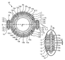
- FIG. 1 is a diagram illustrating the configuration of a steam pipe X reinforced with a reinforcing tool 10.
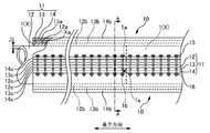
- FIG. 2 is a side view showing the reinforcing tool attached to the straight pipe portion of the steam pipe.
- the diameter of the steam pipe X varies depending on the application, but is determined in the range of 200 mm to 1000 mm, for example. Further, the wall thickness tx of the steam pipe X is set in a range of 40 mm or more and 70 mm or less. The diameter and thickness of the steam pipe X are determined in consideration of various conditions such as the temperature, pressure, flow rate, and flow speed of the power steam.
- the portion to be reinforced in the present embodiment is a straight pipe portion that forms a substantially straight shape of the steam pipe X.
- a straight pipe portion has a plurality of piping members 1 formed to have a predetermined length and welded with their end portions 1 a being abutted against each other in the longitudinal direction. It has a long length.
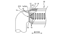
- the end portion Xa in the longitudinal direction of the straight pipe portion of the connected steam pipe X forms a bent portion (so-called elbow portion) bent to approximately 90 degrees, that is, an L shape.
- the end 2a of the piping member 2 is abutted and welded.
- the steam pipe X has a circumferential welded portion 1b welded over the entire circumference in the circumferential direction of the pipe at a plurality of locations in the longitudinal direction.
- a reinforcing tool 10 for reinforcing the creep strength of the steam pipe X is attached to the straight pipe portion of the steam pipe X.
- the reinforcing tool 10 joins a plurality of reinforcing members 11 having a predetermined length along the longitudinal direction of the steam pipe X and disposed along the circumferential direction of the steam pipe X, and reinforcing members adjacent in the circumferential direction.
- each of the partitioned areas is formed by dividing the outer peripheral surface Xb of the steam pipe X into two areas by a virtual plane S passing through the center O of the steam pipe X and extending in the radial direction.
- the two reinforcing members 11 formed so as to substantially cover the steam pipe X are brought into contact with the outer peripheral surface Xb of the steam pipe X from both sides in the radial direction of the steam pipe X so as to sandwich the steam pipe X so as to surround the steam pipe X.
- Each reinforcing member 11 is composed of a plurality of (three in this embodiment) laminated members 12, 13, and 14 that are superposed in the radial direction of the steam pipe X, respectively.
- Each of the laminated members 12, 13, and 14 is formed of a material having a higher creep strength than the material of the steam pipe X (ferritic chromium steel).
- a material having a higher creep strength than the material of the steam pipe X for example, stainless steel, nickel alloy, cobalt alloy, and high chromium steel are used.
- the reinforcement strength with respect to the steam pipe X is raised by making the raw material of each laminated member 12, 13, 14 into a raw material with a creep strength larger than the raw material of the steam pipe X.
- the bolts 15 and the nuts 16 for fixing the adjacent reinforcing members 11 to each other are formed of a material having a higher creep strength than the material of the steam pipe X, like the reinforcing members 11.
- the reinforcing member 11 is made of the same material (for example, SUS304).
- the respective laminated members 12, 13, and 14 are disposed on the outer peripheral surfaces Xb, 12a, and 13a of the steam pipe X or the laminated members 12, 13 that are located on the center O side of the steam pipe X with respect to the respective laminated members 12, 13, and 14.
- Curved portions 12b, 13b, 14b curved to overlap each other along and flange portions 12c, 13c, 14c projecting radially from the circumferential edges of the curved portions 12b, 13b, 14b. It has a plate shape.
- the curved portions 12b, 13b, and 14b of the laminated members 12, 13, and 14 form a portion that surrounds the outer peripheral surface Xb of the steam pipe X, and the flange portions 12c, 13c, and 14c are adjacent to each other. Is a portion for fixing the laminated members 12, 13 and 14 that are adjacent and overlapped in the circumferential direction.
- the laminated member disposed on the innermost circumferential side that is, the steam pipe X side
- a laminated member disposed on the side is referred to as an outer laminated member 14
- a laminated member disposed between the inner laminated member 12 and the outer laminated member 14 is referred to as an intermediate laminated member 13.
- the inner laminated member 12 disposed so as to cover the outer peripheral surface Xb of the steam pipe X on the innermost peripheral side is such that the inner peripheral surface 12d of the curved portion 12b is substantially the same as the radius of curvature of the outer peripheral surface Xb of the steam pipe X.
- the arc length of the curved portion 12b is slightly shorter than the arc length of the steam pipe X.
- the inner peripheral surface 13 d of the curved portion 13 b is formed with a curvature radius substantially the same as the radius of curvature of the outer peripheral surface 12 a of the inner laminated member 12.
- the inner peripheral surface 14 d of the curved portion 14 b is formed with a curvature radius that is substantially the same as the radius of curvature of the outer peripheral surface 13 a of the intermediate laminated member 13. That is, the radius of curvature of the inner surface of the curved portion 13b of the intermediate laminated member 13 is longer than the radius of curvature of the inner peripheral surface 12d of the curved portion 12b of the inner laminated member 12 by the thickness 12t of the inner laminated member 12, and The radius of curvature of the inner peripheral surface 14d of the curved portion 14b is formed to be 13t longer than the radius of curvature of the inner peripheral surface 14d of the curved portion 13b of the intermediate laminated member 13 by the thickness 13t.
- the flange portions 12c, 13c, and 14c protruding in the radial direction from the circumferential edges of the curved portion 12b of the inner laminated member 12, the curved portion 13b of the intermediate laminated member 13, and the curved portion 14b of the outer laminated member 14 are respectively Projecting in the opposite directions toward the outside of the curved portions 12b, 13b, 14b.
- the flange portion 12c of the inner laminated member 12, the flange portion 13c of the intermediate laminated member 13, and the flange portion 14c of the outer laminated member 14 are overlapped by the inner laminated member 12, the intermediate laminated member 13, and the outer laminated member 14.
- the flange portions 12c, 13c, and 14c are configured to overlap each other when being combined.
- a shaft portion 15a of a bolt 15 for fixing the adjacent reinforcing members 11 is inserted into each flange portion 12c, 13c, 14c so as to pass through each flange portion 12c, 13c, 14c in the thickness direction.
- a plurality of holes 12e, 13e, and 14e are provided at appropriate intervals along the longitudinal direction of the steam pipe X, that is, along the longitudinal direction of the inner laminated member 12, the intermediate laminated member 13, and the outer laminated member 14.
- the diameters of the through holes 12e, 13e, and 14e are larger than the diameter of the shaft portion 15a of the bolt 15 to be inserted, and smaller than the sizes of the head portion 15b and the nut 16 of the bolt 15.
- the reinforcing member 10 included in the reinforcing tool 10 is two, the two reinforcing members 11 are adjacent to each other.
- the flange portions 12c of the inner laminated members 12 face each other with an interval therebetween, and the two inner laminated layers A gap sp is generated between the flange portions 12 c of the member 12. That is, the sum of the lengths in the circumferential direction of the curved portion 12b of the inner laminated member 12 included in the two reinforcing members 11 is set to a length at which the gap sp is generated.
- the gap sp is formed by each reinforcing member 11 in order to suppress the expansion of the steam pipe X.
- the flanges 12c, 13c, and 14c are brought close to each other and fixed with bolts 15 and nuts 16, thereby pulling the curved portions 12b, 13b, and 14b in the circumferential direction by the gap sp. Can do.
- the steam pipe X is fastened by the curved portions 12b, 13b, and 14b, and the expansion of the steam pipe X can be countered.
- each reinforcing member 11 of the two reinforcing members 11 is disposed on one half of the steam pipe X.
- the other reinforcing member 11 is disposed on the opposite side of the steam pipe X.
- each reinforcing member 11 is a large member that is long in the longitudinal direction and is heavier.
- the middle laminated member 13 and the outer laminated member 14 are overlapped and arranged so as to surround the steam pipe X.
- the flange portions 12c, 13c, and 14c of the two reinforcing members 11 arranged so as to be adjacent to each other are fastened and fixed with bolts 15 and nuts 16. Thereby, the reinforcing tool 10 is attached to the steam pipe X.
- the reinforcing member 11 When the steam pipe X expands in a state where the steam pipe X is reinforced by overlapping the positions in the longitudinal direction of the plurality of laminated members 12, 13, and 14 constituting the reinforcing member 11 without shifting each other, the reinforcing member 11 is surrounded. The bending stress is concentrated at the boundary between the part that is present and the part that is not enclosed. As described above, the steam pipe X has the circumferential welded portion 1b in which the plurality of piping members 1 are joined by joining the end portions 1a to each other, and bending stress is concentrated in the vicinity of the circumferential welded portion 1b. It is desirable to prevent this.
- the boundary portion in the circumferential welded portion 1b in the straight pipe portion of the steam pipe X, in the vicinity of the circumferential welded portion 1b, the boundary between the portion surrounded by the reinforcing member 11 and the portion not surrounded (hereinafter referred to as the boundary portion).
- the reinforcing tool 10 is arranged so that is not located.
- the boundary portion must be disposed in the vicinity of the circumferential welded portion 1b, such as a portion where the end portion 2a of the piping member 2 forming the bent portion is abutted and welded, the end portion of the reinforcing member 11 On the side, the number of laminated members 12, 13, and 14 is reduced.
- the through holes 12 e (see FIG. 3) provided at the extreme end of the inner laminated member 12 have the reinforcing members 11 adjacent to each other.
- Bolts 15 for fixing only the inner laminated members 12 are inserted.
- the inner laminated member 13 is laminated so that the through hole 12e provided second from the end of the inner laminated member 12 and the through hole 13e provided at the end of the intermediate laminated member 13 (see FIG. 3) overlap.
- the bolts 15 for fixing the inner laminated member 12 and the middle laminated member 13 of the two reinforcing members 11 are inserted into the through holes 12e and 13e that are overlapped with the member 12 and overlapped.
- a through hole 12e provided third from the end of the inner laminated member 12, a through hole 13e provided second from the end of the intermediate laminated member 13, and a through hole 14e provided at the end of the outer laminated member 14 (See FIG. 3), the outer laminated member 14 and the middle laminated member 13 are overlaid on the inner laminated member 12, and the two laminated reinforcing members 11 are laminated on the laminated through holes 12 e, 13 e, 14 e.
- Bolts 15 for fixing the member 14, the middle laminated member 13 and the inner laminated member 12 are inserted.
- the bending stress concentration is increased by gradually increasing the number of the laminated members 12, 13, and 14 to be laminated as the distance from the end of the reinforcing member 11 increases. Is prevented.
- the outer laminated member 14 projects in the longitudinal direction from the middle laminated member 13 and the inner laminated member 12 at the end opposite to the circumferential welded portion 1 b, and the middle laminated member 13 is the inner laminated member 12.
- the steam pipe X can be reinforced by the reinforcing member 11 having the same thickness.
- the plurality of reinforcing members 11 joined in the circumferential direction and surrounding the steam pipe X are composed of the plurality of laminated members 12, 13, and 14.
- the laminated members 12, 13, and 14 can be handled as separate bodies.
- the laminated members 12, 13, and 14 that are lighter than the integrally formed reinforcing member are overlapped, and the reinforcing members 11 that are laminated with the laminated members 12, 13, and 14 are combined. Since it is only joined together, installation work such as handling is easy.
- the flanges 12c, 13c, and 14c adjacent to each other can be fixed by screwing the nut 16 to the bolt 15 to simplify the configuration and reinforce the steam pipe X by a simple operation. It is possible.
- the flange portions 12c of the inner laminated member in the joined reinforcing member 11 are spaced apart from each other. Therefore, the bent portions 12b, 13b, and 14b can be reliably brought into contact with the steam pipe X by fixing the bolts 15 close to each other so that the flanges 12c, 13c, and 14c are attracted to each other by the nut 16. Therefore, the expansion of the steam pipe X can be suppressed.
- the reinforcing member 11 configured by laminating the laminated members 12, 13, and 14 is, in the vicinity of the circumferential welded portion 1b of the steam pipe X, in the direction away from the circumferential welded portion 1b. Since the laminated members 12, 13, and 14 are arranged so that the number of laminated layers 13 and 14 is increased, it is possible to reduce stress concentration on the circumferential welded portion 1b.
- each of the laminated members 12, 13, and 14 is formed of a metal having a creep strength higher than that of the metal constituting the steam pipe X to be reinforced, the proof stress of the reinforcing member 11 is increased. It is possible.
- the number of the laminated members 12, 13, and 14 included in each reinforcing member 11 is three, but is not limited thereto.
- the flange portion may be formed by molding or the like so that the thickness of the flange portion is larger than the thickness of the curved portion. This is because a large load is applied to the flange when it is fixed with bolts and nuts.
- the thickness of the flange is less than the thickness of the curved part so that it can withstand the tightening force of the bolt and nut. May be larger.
- the plate thickness of the flange portion may be set to twice the plate thickness of the curved portion, or may be set to a ratio of 2 to 3 times.
- the above-mentioned fixing member is constituted by the bolt 15 and the nut 16, it is not limited to this configuration.
- the piping is not limited to the one that flows power steam.
- the present invention can be applied to any steam pipe X through which high-temperature and high-pressure steam similar to power steam flows and which undergoes creep degradation.
Landscapes
- Engineering & Computer Science (AREA)
- General Engineering & Computer Science (AREA)
- Mechanical Engineering (AREA)
- Protection Of Pipes Against Damage, Friction, And Corrosion (AREA)
- Physics & Mathematics (AREA)
- Thermal Sciences (AREA)
- Heat-Exchange Devices With Radiators And Conduit Assemblies (AREA)
Abstract
Description
まず、2つの補強部材11のうちの一方の補強部材11を蒸気配管Xの片半部分に配置した後、他方の補強部材11を蒸気配管Xの反対側の部分に配置する。このとき、各補強部材11は、長手方向に長い大きな部材であり重量が嵩むため、積層部材12を1枚ずつ蒸気配管Xの片半部分及びの反対側の部分に配置しつつ、内積層部材12、中積層部材13、及び、外積層部材14を重ね合わせて蒸気配管Xを囲繞するように配置する。そして、互いに隣り合うように配置された2つの補強部材11のフランジ部12c、13c、14c同士をボルト15とナット16で締め付けて固定する。これにより、補強用具10が蒸気配管Xに取り付けられる。
Claims (7)
- 内部の高温高圧流体によってクリープが生じる金属製の配管の外周面に沿って当該配管を周方向に囲繞する状態で配置され、前記配管のクリープ強度を補強する補強用具であって、
前記周方向に配置され複数の補強部材が接合されてなり、
各々の前記補強部材は、前記配管の径方向に重ね合わせられる複数の積層部材にて構成されていることを特徴とする補強用具。 - 前記積層部材は、前記配管の周方向に沿って湾曲された湾曲部、及び、前記湾曲部の前記周方向における縁から前記径方向に突出されたフランジ部を有し、
互いに隣り合う前記補強部材が有する前記複数の積層部材の前記フランジ部同士が固定部材にて固定されて前記複数の補強部材が接合されることを特徴とする請求項1に記載の補強用具。 - 前記フランジ部には、当該フランジの厚み方向に貫通する貫通孔が設けられており、
前記固定部材は、軸部が前記貫通孔に挿通されるボルトと、前記ボルトに螺合されるナットとであることを特徴とする請求項1または請求項2に記載の補強用具。 - 前記補強部材は、互いに隣り合う前記補強部材が接合されて前記配管を囲繞した際に、接合されている前記補強部材の前記フランジ部間は、互いに間隔が隔てられていることを特徴とする請求項1乃至請求項3のいずれかに記載の補強用具。
- 前記フランジ部の厚みは、前記湾曲部の厚みよりも大きいことを特徴とする請求項1乃至請求項4のいずれかに記載の補強用具。
- 前記配管は、複数の配管部材が突き合わせられて溶接された溶接部を有し、
前記溶接部においては、当該溶接部から離れる方向に向かって、前記積層部材の積層数が大きくなるように前記積層部材が配置されることを特徴とする請求項1乃至請求項5のいずれかに記載の補強用具。 - 前記補強部材は、前記配管を構成する金属よりもクリープ強度が高い金属で形成されていることを特徴とする請求項1乃至請求項6のいずれかに記載の補強用具。
Priority Applications (6)
| Application Number | Priority Date | Filing Date | Title |
|---|---|---|---|
| JP2013557305A JP5579943B1 (ja) | 2013-02-01 | 2013-02-01 | 配管用の補強用具 |
| PCT/JP2013/052395 WO2014118974A1 (ja) | 2013-02-01 | 2013-02-01 | 配管用の補強用具 |
| EP13873881.0A EP2952799B1 (en) | 2013-02-01 | 2013-02-01 | Pipe-reinforcing implement |
| KR1020157021628A KR20150104203A (ko) | 2013-02-01 | 2013-02-01 | 배관용의 보강용구 |
| US14/764,860 US9829144B2 (en) | 2013-02-01 | 2013-02-01 | Pipe-reinforcing implement |
| CN201380071871.6A CN104956138A (zh) | 2013-02-01 | 2013-02-01 | 配管用的加固用具 |
Applications Claiming Priority (1)
| Application Number | Priority Date | Filing Date | Title |
|---|---|---|---|
| PCT/JP2013/052395 WO2014118974A1 (ja) | 2013-02-01 | 2013-02-01 | 配管用の補強用具 |
Publications (1)
| Publication Number | Publication Date |
|---|---|
| WO2014118974A1 true WO2014118974A1 (ja) | 2014-08-07 |
Family
ID=51261716
Family Applications (1)
| Application Number | Title | Priority Date | Filing Date |
|---|---|---|---|
| PCT/JP2013/052395 Ceased WO2014118974A1 (ja) | 2013-02-01 | 2013-02-01 | 配管用の補強用具 |
Country Status (6)
| Country | Link |
|---|---|
| US (1) | US9829144B2 (ja) |
| EP (1) | EP2952799B1 (ja) |
| JP (1) | JP5579943B1 (ja) |
| KR (1) | KR20150104203A (ja) |
| CN (1) | CN104956138A (ja) |
| WO (1) | WO2014118974A1 (ja) |
Cited By (2)
| Publication number | Priority date | Publication date | Assignee | Title |
|---|---|---|---|---|
| JP2017156065A (ja) * | 2016-03-04 | 2017-09-07 | 中国電力株式会社 | ボイラ管の補強装置、ボイラ管の補強方法 |
| EP3327348A4 (en) * | 2015-07-22 | 2018-08-01 | The Chugoku Electric Power Co., Inc. | Pipe reinforcement device and pipe reinforcement method |
Families Citing this family (5)
| Publication number | Priority date | Publication date | Assignee | Title |
|---|---|---|---|---|
| JP6137432B1 (ja) * | 2016-03-25 | 2017-05-31 | 中国電力株式会社 | ボイラ管の補強装置、ボイラ管の補強方法 |
| WO2018042577A1 (ja) * | 2016-08-31 | 2018-03-08 | 中国電力株式会社 | 配管の補強構造及び配管の補強方法 |
| CN111810765A (zh) * | 2020-07-01 | 2020-10-23 | 江苏烨欣塑业有限公司 | 一种农田节水灌溉专用管快速补漏方法 |
| KR102565209B1 (ko) * | 2022-03-23 | 2023-08-09 | 주식회사 대성종합엔지니어링건축사사무소 | 상하수도, 도시계획 도로, 매립장 지반에 매립된 침출수 배출용 관거 보강 방법 및 보강 구조 |
| FR3158133A1 (fr) * | 2024-01-10 | 2025-07-11 | L'air Liquide, Société Anonyme Pour L’Étude Et L'exploitation Des Procédés Georges Claude | Dispositif de renfort d’un équipement sous pression |
Citations (6)
| Publication number | Priority date | Publication date | Assignee | Title |
|---|---|---|---|---|
| JPS61112515A (ja) * | 1984-11-05 | 1986-05-30 | 六寶産業株式会社 | 海底ケ−ブルの保護管の敷設方法 |
| JP2001020330A (ja) * | 1999-07-09 | 2001-01-23 | Inoac Corp | 水道配管用保護カバー |
| JP2003014163A (ja) * | 2001-06-29 | 2003-01-15 | Mitsubishi Heavy Ind Ltd | 水圧管補強方法、水圧管補強部材、水圧管補強のための繊維強化樹脂 |
| JP2007071360A (ja) * | 2005-09-09 | 2007-03-22 | Chugoku Electric Power Co Inc:The | 高温中空部材の補強方法 |
| JP2011185403A (ja) | 2010-03-10 | 2011-09-22 | Chugoku Electric Power Co Inc:The | 中空の金属部材の補強構造、中空の金属部材の補強方法 |
| JP3177409U (ja) * | 2012-05-21 | 2012-08-02 | 騰 翔 何 | チューブ用漏れ止め構造 |
Family Cites Families (25)
| Publication number | Priority date | Publication date | Assignee | Title |
|---|---|---|---|---|
| US31614A (en) * | 1861-03-05 | Waterproof hose | ||
| US1416460A (en) * | 1919-08-09 | 1922-05-16 | American Steam Convyor Corp | Method of making cast-iron pipe sections |
| US2267817A (en) * | 1937-08-30 | 1941-12-30 | Louis J Costa | Pipe fitting of felted asbestos and cement |
| US2716788A (en) * | 1952-04-05 | 1955-09-06 | Bridgeport Fabrics Inc | Beading or weather strip and method of making same |
| US3044498A (en) * | 1957-03-25 | 1962-07-17 | Foil Process Corp | Foil tubing |
| FR1189044A (fr) * | 1957-12-27 | 1959-09-28 | Fabrication De Tubes En Matier | Procédé de pose de canalisations sous coquilles de protection |
| US2946395A (en) * | 1958-09-03 | 1960-07-26 | Bernard O Overland | Muffler repair kit |
| NL130347C (ja) * | 1966-03-25 | |||
| US3996968A (en) * | 1973-01-23 | 1976-12-14 | E. I. Du Pont De Nemours And Company | Tubing articles |
| JPS5652689A (en) | 1979-10-02 | 1981-05-11 | Doryokuro Kakunenryo | Protection mechanism of pipings |
| US4478661A (en) * | 1981-03-20 | 1984-10-23 | Dayco Corporation | Method of making a reinforced collapsible hose construction |
| US4523738A (en) * | 1982-03-05 | 1985-06-18 | Red Valve Co. Inc. | Deformable sleeve for a pinch valve |
| US4433732A (en) * | 1982-04-06 | 1984-02-28 | Minnesota Mining And Manufacturing Company | Cable tray protection system |
| DE3708006A1 (de) * | 1987-03-12 | 1988-09-22 | Kautex Maschinenbau Gmbh | Verfahren zum herstellen von hohlkoerpern aus thermoplastischem kunststoff mit einer mehrschichtigen wandung |
| GR1002280B (el) * | 1991-09-27 | 1996-05-02 | Mcneil-Ppc Inc. | Απορροφητικον αντικειμενο το οποιο εχει παραθυρο προσβολης. |
| US5288108A (en) * | 1992-10-05 | 1994-02-22 | Cascade Waterworks Manufacturing Co. | Bell joint repair clamp |
| CN2182918Y (zh) | 1994-02-23 | 1994-11-16 | 哈尔滨哈玻业余复合材料技术咨询所 | 玻璃钢煤气管道进户保护罩 |
| US8141592B2 (en) * | 2004-12-03 | 2012-03-27 | Illinois Tool Works Inc. | System and method for pipe repair |
| JP2006249885A (ja) | 2005-03-14 | 2006-09-21 | Univ Chuo | 長柱鋼管の座屈補強方法 |
| US7946311B2 (en) * | 2007-02-01 | 2011-05-24 | Hobart Brorthers Company | Robust preconditioned air hose |
| US9689512B2 (en) * | 2009-02-20 | 2017-06-27 | Hobart Brothers Company | Air hose delivery assembly with inner liner |
| GB2475982A (en) * | 2009-12-07 | 2011-06-08 | Subsea 7 Ltd | Pipe clamp device and repairing pipes |
| US8113242B1 (en) * | 2010-01-19 | 2012-02-14 | Odyssian Technology, Llc | Composite repair for pipes |
| US8631829B1 (en) * | 2010-01-19 | 2014-01-21 | Odyssian Technology, Llc | Composite repair for pipes and monitoring assembly |
| CN202419041U (zh) * | 2012-01-20 | 2012-09-05 | 徐祥珠 | 便于快速安装的蒸汽管道保温套管 |
-
2013
- 2013-02-01 CN CN201380071871.6A patent/CN104956138A/zh active Pending
- 2013-02-01 US US14/764,860 patent/US9829144B2/en not_active Expired - Fee Related
- 2013-02-01 WO PCT/JP2013/052395 patent/WO2014118974A1/ja not_active Ceased
- 2013-02-01 JP JP2013557305A patent/JP5579943B1/ja not_active Expired - Fee Related
- 2013-02-01 EP EP13873881.0A patent/EP2952799B1/en active Active
- 2013-02-01 KR KR1020157021628A patent/KR20150104203A/ko not_active Ceased
Patent Citations (6)
| Publication number | Priority date | Publication date | Assignee | Title |
|---|---|---|---|---|
| JPS61112515A (ja) * | 1984-11-05 | 1986-05-30 | 六寶産業株式会社 | 海底ケ−ブルの保護管の敷設方法 |
| JP2001020330A (ja) * | 1999-07-09 | 2001-01-23 | Inoac Corp | 水道配管用保護カバー |
| JP2003014163A (ja) * | 2001-06-29 | 2003-01-15 | Mitsubishi Heavy Ind Ltd | 水圧管補強方法、水圧管補強部材、水圧管補強のための繊維強化樹脂 |
| JP2007071360A (ja) * | 2005-09-09 | 2007-03-22 | Chugoku Electric Power Co Inc:The | 高温中空部材の補強方法 |
| JP2011185403A (ja) | 2010-03-10 | 2011-09-22 | Chugoku Electric Power Co Inc:The | 中空の金属部材の補強構造、中空の金属部材の補強方法 |
| JP3177409U (ja) * | 2012-05-21 | 2012-08-02 | 騰 翔 何 | チューブ用漏れ止め構造 |
Non-Patent Citations (1)
| Title |
|---|
| See also references of EP2952799A4 |
Cited By (2)
| Publication number | Priority date | Publication date | Assignee | Title |
|---|---|---|---|---|
| EP3327348A4 (en) * | 2015-07-22 | 2018-08-01 | The Chugoku Electric Power Co., Inc. | Pipe reinforcement device and pipe reinforcement method |
| JP2017156065A (ja) * | 2016-03-04 | 2017-09-07 | 中国電力株式会社 | ボイラ管の補強装置、ボイラ管の補強方法 |
Also Published As
| Publication number | Publication date |
|---|---|
| JP5579943B1 (ja) | 2014-08-27 |
| US20160040821A1 (en) | 2016-02-11 |
| EP2952799A4 (en) | 2016-10-05 |
| EP2952799B1 (en) | 2020-09-23 |
| KR20150104203A (ko) | 2015-09-14 |
| CN104956138A (zh) | 2015-09-30 |
| US9829144B2 (en) | 2017-11-28 |
| JPWO2014118974A1 (ja) | 2017-01-26 |
| EP2952799A1 (en) | 2015-12-09 |
Similar Documents
| Publication | Publication Date | Title |
|---|---|---|
| JP5579943B1 (ja) | 配管用の補強用具 | |
| CN203292697U (zh) | 使用镀覆材料的异材接头 | |
| EP3224519B1 (en) | Fluid conduit element and method for producing the fluid conduit element | |
| JP5415588B2 (ja) | 蒸気配管用の補強用具 | |
| WO2017013753A1 (ja) | 配管の補強装置、配管の補強方法 | |
| JP6137432B1 (ja) | ボイラ管の補強装置、ボイラ管の補強方法 | |
| JP6663644B2 (ja) | 二重管構造およびその継手 | |
| JP5982879B2 (ja) | 溶接組立h形鋼 | |
| JP6271291B2 (ja) | 配管用シール構造及び建屋 | |
| JP2012117610A (ja) | 配管材の接続構造 | |
| JP2007040443A (ja) | プラスチック管の継手構造 | |
| KR20120019895A (ko) | 배관 부재 관통 구조 | |
| KR100593248B1 (ko) | 관 모양의 부품을 위한 연결 플랜지 | |
| JP2010065478A (ja) | 補鋼材付き鋼管の製造方法 | |
| JP6142974B1 (ja) | 配管の補強構造及び配管の補強方法 | |
| JP5979907B2 (ja) | 継手構造及び継手方法 | |
| JP5579950B2 (ja) | 蒸気用配管 | |
| RU2686129C1 (ru) | Способ соединения металлических труб с внутренней пластмассовой облицовкой | |
| JP2007232133A (ja) | うず巻き形ガスケット | |
| JP2019157874A (ja) | 大径管用フランジ式管継手 | |
| JP6254011B2 (ja) | 配管用シール構造及び建屋 | |
| RU2628972C2 (ru) | Способ ремонта трубопровода, смонтированного из труб с внутренним покрытием | |
| JP2020153426A (ja) | 配管離脱防止機構 | |
| JP6564605B2 (ja) | アライメント用配管、アライメント方法及びアライメント用配管の製造方法 | |
| HK40019110A (en) | Pipe joint and method for assembling pipe joint |
Legal Events
| Date | Code | Title | Description |
|---|---|---|---|
| ENP | Entry into the national phase |
Ref document number: 2013557305 Country of ref document: JP Kind code of ref document: A |
|
| 121 | Ep: the epo has been informed by wipo that ep was designated in this application |
Ref document number: 13873881 Country of ref document: EP Kind code of ref document: A1 |
|
| NENP | Non-entry into the national phase |
Ref country code: DE |
|
| ENP | Entry into the national phase |
Ref document number: 20157021628 Country of ref document: KR Kind code of ref document: A |
|
| WWE | Wipo information: entry into national phase |
Ref document number: 2013873881 Country of ref document: EP |
|
| WWE | Wipo information: entry into national phase |
Ref document number: 14764860 Country of ref document: US |