WO2014119320A1 - Dye-sensitized solar cell (dsc) with energy-donor enhancement, method for fabricating dsc and method for generating photocurrent using dsc - Google Patents
Dye-sensitized solar cell (dsc) with energy-donor enhancement, method for fabricating dsc and method for generating photocurrent using dsc Download PDFInfo
- Publication number
- WO2014119320A1 WO2014119320A1 PCT/JP2014/000494 JP2014000494W WO2014119320A1 WO 2014119320 A1 WO2014119320 A1 WO 2014119320A1 JP 2014000494 W JP2014000494 W JP 2014000494W WO 2014119320 A1 WO2014119320 A1 WO 2014119320A1
- Authority
- WO
- WIPO (PCT)
- Prior art keywords
- dye
- dsc
- wavelength
- type semiconductor
- sensitized
- Prior art date
- Legal status (The legal status is an assumption and is not a legal conclusion. Google has not performed a legal analysis and makes no representation as to the accuracy of the status listed.)
- Ceased
Links
Images







Classifications
-
- H—ELECTRICITY
- H01—ELECTRIC ELEMENTS
- H01G—CAPACITORS; CAPACITORS, RECTIFIERS, DETECTORS, SWITCHING DEVICES, LIGHT-SENSITIVE OR TEMPERATURE-SENSITIVE DEVICES OF THE ELECTROLYTIC TYPE
- H01G9/00—Electrolytic capacitors, rectifiers, detectors, switching devices, light-sensitive or temperature-sensitive devices; Processes of their manufacture
- H01G9/20—Light-sensitive devices
- H01G9/2059—Light-sensitive devices comprising an organic dye as the active light absorbing material, e.g. adsorbed on an electrode or dissolved in solution
- H01G9/2063—Light-sensitive devices comprising an organic dye as the active light absorbing material, e.g. adsorbed on an electrode or dissolved in solution comprising a mixture of two or more dyes
-
- H—ELECTRICITY
- H01—ELECTRIC ELEMENTS
- H01G—CAPACITORS; CAPACITORS, RECTIFIERS, DETECTORS, SWITCHING DEVICES, LIGHT-SENSITIVE OR TEMPERATURE-SENSITIVE DEVICES OF THE ELECTROLYTIC TYPE
- H01G9/00—Electrolytic capacitors, rectifiers, detectors, switching devices, light-sensitive or temperature-sensitive devices; Processes of their manufacture
- H01G9/20—Light-sensitive devices
- H01G9/2027—Light-sensitive devices comprising an oxide semiconductor electrode
- H01G9/2031—Light-sensitive devices comprising an oxide semiconductor electrode comprising titanium oxide, e.g. TiO2
-
- H—ELECTRICITY
- H10—SEMICONDUCTOR DEVICES; ELECTRIC SOLID-STATE DEVICES NOT OTHERWISE PROVIDED FOR
- H10K—ORGANIC ELECTRIC SOLID-STATE DEVICES
- H10K85/00—Organic materials used in the body or electrodes of devices covered by this subclass
- H10K85/30—Coordination compounds
- H10K85/311—Phthalocyanine
-
- Y—GENERAL TAGGING OF NEW TECHNOLOGICAL DEVELOPMENTS; GENERAL TAGGING OF CROSS-SECTIONAL TECHNOLOGIES SPANNING OVER SEVERAL SECTIONS OF THE IPC; TECHNICAL SUBJECTS COVERED BY FORMER USPC CROSS-REFERENCE ART COLLECTIONS [XRACs] AND DIGESTS
- Y02—TECHNOLOGIES OR APPLICATIONS FOR MITIGATION OR ADAPTATION AGAINST CLIMATE CHANGE
- Y02E—REDUCTION OF GREENHOUSE GAS [GHG] EMISSIONS, RELATED TO ENERGY GENERATION, TRANSMISSION OR DISTRIBUTION
- Y02E10/00—Energy generation through renewable energy sources
- Y02E10/50—Photovoltaic [PV] energy
- Y02E10/542—Dye sensitized solar cells
Definitions
- This invention generally relates to dye-sensitive light absorbing chemistry and, more particularly, to dye-sensitized solar cells (DSCs) demonstrating enhanced photovoltaic performance with energy-donor materials in the electrolyte and to dye-sensitized solar cells (DSCs) co-sensitized with two dyes.
- DSCs dye-sensitized solar cells
- DSCs dye-sensitized solar cells
- PCEs power conversion efficiencies
- sensitizing dyes suffer from a deficiency in optical absorption beyond 700 nanometers (nm).
- the choice of sensitizer is typically limited to those exhibiting broad absorption yet weak absorbance, or strong absorbance over a narrow wavelength region. In both cases, a considerable fraction of the incident sunlight fails to be effectively harnessed.
- porphyrins Although shown to be efficient sensitizers for DSC, the typical optical absorption features of porphyrins are dominated by strong absorbance at shorter wavelengths (Soret band), weaker absorbance at longer wavelengths (Q-bands), and with absorbance approaching zero in the intermittent region. Overall, the deficiency in absorbance over broad wavelength regions necessarily places limitations on porphyrin performance in DSC. Nevertheless, the more recently demonstrated potential for porphyrin sensitizers has positioned this class of materials as a legitimate rival to traditional ruthenium complexes for DSC applications. 1
- PTCDI tetra-(4-tert-butylphenoxy)perylene tetracarboxylic acid dimide
- TT1 zinc tri-tert-butyl-phthalocyanine
- Hardin et al. employed 4-(dicyanomethylene)-2-methyl-6-(4-dimethylaminostyryl)-4H-pyran as ERD in combination with a near-IR (NIR) sensitizer (TT1) to increase PCE from 3.5% to 4.5% in DSC. 7 Furthermore, an excitation transfer efficiency of 96% was determined for the ERD in TT1-sensitized TiO 2 films.
- Shankar et al. reported the occurrence of FRET with near quantitative energy transfer efficiency between a zinc phthalocyanine (ZnPc-TTB) dissolved in electrolyte and TiO 2 nanowire-bound ruthenium dyes in DSC.
- ZnPc-TTB zinc phthalocyanine
- IPCE values Upon introduction of N877 (10 mM concentration) into the solid-state hole transport material (Spiro-OMeTAD), IPCE values increased to 8% and 21% at 460 nm and 400 nm, respectively, which was accompanied by corresponding increases in J sc and PCE of 30% and 29%, respectively.
- Mor et al. reported a FRET-based maximum IPCE contribution of 25% with a corresponding excitation energy transfer efficiency ⁇ 67.5% for a TiO 2 nanotube-based ssDSC using a squarine-based (SQ-1) sensitizer in combination with an ERD. 13 Brown et al.
- Siegers et al. described the utilization of energy transfer to improve light harvesting and photocurrent generation in DSC based upon a co-sensitized system consisting of a carboxy-functionalized 4-aminonaphthalimide dye (carboxy-fluorol) as donor and N719 dye as acceptor. 16 Similarly, Hardin et al. demonstrated successful photocurrent generation via intermolecular energy transfer from an NIR-absorbing zinc naphthalocyanine (AS02) co-sensitized with a metal complex dye (C106) on the TiO 2 surface. 17,18 Griffith et al. reported a 300% efficiency enhancement in DSC using co-sensitization with two porphyrins for which IPCE data indicated an improved charge injection yield.
- AS02 NIR-absorbing zinc naphthalocyanine
- C106 metal complex dye
- Zaban "Built-in Quantum Dot Antennas in Dye-Sensitized Solar Cells", ACS Nano 2010, 4, 1293-1298. 11. S. Itzhakov, S. Buhbut, E. Tauber, T. Geiger, A. Zaban and D. Oron, "Design Principles of FRET-Based Dye-Sensitized Solar Cells with Buried Quantum Dot Donors", Advanced Energy Materials 2011, 1, 626-633. 12. J-H. Yum, B. E. Hardin, S-J. Moon, E. Baranoff, F. Nu(u-umlaut)esch, M. D. McGehee, M. Gra(a-umlaut)tzel and M. K.
- an energy-door material could be used in cooperation with a sensitizing dye to improve both the degree of optical absorbance and the range of wavelengths over which a DSC operates.
- DSCs dye-sensitized solar cells
- a method for fabricating a dye-sensitized solar cell with energy-donor enhancement.
- a transparent conductive oxide (TCO) film is formed overlying a transparent substrate, and an n-type semiconductor layer is formed overlying the TCO.
- the n-type semiconductor layer is exposed to a dissolved dye (D1) having a first optical absorbance local maxima at a first wavelength (A1) and a second optical absorbance local maxima at a second wavelength (A2), longer than the first wavelength.
- D1 dissolved dye having a first optical absorbance local maxima at a first wavelength (A1) and a second optical absorbance local maxima at a second wavelength (A2), longer than the first wavelength.
- the n-type semiconductor layer is functionalized with the dye (D1), forming a sensitized n-type semiconductor layer.
- a redox electrolyte that includes a dissolved energy-donor material (ED1) in contact with the sensitized n-type semiconductor layer.
- the energy-donor material (ED1) is capable of non-radiative energy transfer to the dye (D1).
- the energy-donor material (ED1) has a third optical absorbance local maxima at a third wavelength (A3) between the first wavelength (A1) and the second wavelength (A2), and a first optical emission local maxima between the third wavelength (A3) and the second wavelength (A2).
- a counter electrode is formed overlying the redox electrolyte.
- Fig. 1 is partial cross-sectional view of a dye-sensitized solar cell (DSC) with energy-donor enhancement.
- Fig. 2 is a partial cross-sectional view depicting a variation of the DSC of Fig. 1.
- Fig. 3 is a graph of conceptual absorbance and emission values vs. wavelength, associated with the DSC of Figs. 1 and 2.
- Fig. 4 is a graph of conceptual incident photon-to-current conversion efficiency (IPCE) values vs. wavelength, associated with the DSC of Figs. 1 and 2.
- IPCE incident photon-to-current conversion efficiency
- FIG. 5 is a diagram depicting the molecularstructure of 1,6,9-tris-(4-tert-butylphenoxy)-N-(2,6-diisopropyl phenyl)perylene-3,4-dicarboximide (TTBPP).
- Fig. 6 is an illustration of effective spectral matching for Fo(o-umlaut)rsterresonance energy transfer (FRET) from a photo-excited energy-donor to a sensitizingdye.
- Fig. 7 is an illustration of the operative mechanisms in FRET-basedDSC.
- Fig. 8 is a graph depicting the optical absorption spectra of ZnP andTTBPP in dichloromethane (DCM), and ZnP co-adsorbed onto transparent TiO 2 substrates with deoxycholic acid (DCA) at a 1:1 molar ratio from 375-725 nm.
- Fig. 9 is a graph depicting the optical absorption spectra of ZnP andTTBPP in dichloromethane (DCM), and ZnP co-adsorbed onto transparent TiO 2 substrates with deoxycholic acid (DCA) at a 1:1 molar ratio from 375-725 nm.
- Fig. 10 is a graph of IPCE spectra for DSCs fabricated using ZnP withtriiodide electrolyte and ZnP containing 6 mM dissolved TTBPP in triiodideelectrolyte from 300-800 nm.
- Fig. 11 is a graph of the photovoltaic characteristics for a DSCfabricated using ZnP with triiodide electrolyte, containing 6 mM dissolvedTTBPP.
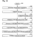
- Fig. 12 is a flowchart illustrating a method for fabricating adye-sensitized solar cell with energy-donor enhancement.
- Fig. 13 is a flowchart illustrating a method for generating photocurrentusing a dye-sensitized solar cell with energy-donor enhancement.
- Fig. 14 is a partial cross-sectional view of a co-sensitizeddye-sensitized solar cell (DSC).
- Fig. 15 is a graph of conceptual absorbance values vs. wavelength, associatedwith the DSC of Fig. 14.
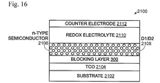
- Fig. 16 is a partial cross-sectional view depicting a variation of theDSC of Fig. 14.
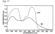
- Fig. 17 is a graph depicting the optical absorption spectra of ZnP andBD adsorbed separately onto transparent TiO 2 substrates from 375-900nm.
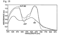
- Fig. 18 is a graph depicting the optical absorption spectra of ZnP, BD,and ZnP:BD (1:1) adsorbed separately onto transparent TiO 2 substrates from 375-900 nm.
- Fig. 15 is a graph of conceptual absorbance values vs. wavelength, associatedwith the DSC of Fig. 14.
- Fig. 16 is a partial cross-sectional view depicting a variation of theDSC of
- Fig. 19 is a graph depicting the optical absorption spectra of ZnP, BD,and ZnP:BD (1:4) adsorbed separately onto transparent TiO 2 substrates from 375-900 nm.
- Fig. 20 is a graph depicting the incident photon-to-current conversionefficiency (IPCE) spectra for DSCs fabricated from ZnP, BD, and ZnP:BD (1:4)sensitized TiO 2 substrates from 300-900 nm.
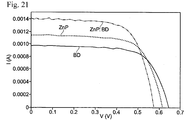
- Fig. 21 is a graph depicting the I-V characteristics for DSCsfabricated from ZnP, BD, and ZnP:BD (1:4) sensitized TiO 2 substrates.
- Fig. 22 is a flowchart illustrating a method for fabricating a co-sensitized dye-sensitized solar cell.
- Fig. 1 is partial cross-sectional view of a dye-sensitized solar cell (DSC) with energy-donor enhancement.
- the DSC 100 comprises a transparent substrate 102, such as glass, and a transparent conductive oxide (TCO) film 104 overlying the transparent substrate 102.
- TCO materials include fluorine-doped tin oxide (FTO) and indium tin oxide (ITO).
- An n-type semiconductor layer 106 overlies the TCO film 104, and is sensitized with a dye (D1) 108.
- the dye (D1) 108 is capable of charge transfer at a surface of the n-type semiconductor 106.
- the dye (D1) 108 is functionalized to the n-type semiconductor layer 106.
- the functionalization of the n-type semiconductor implies the establishment of an intimate association between the dye and the n-type semiconductor surface through chemical bonding, complexation, and/or other modes through which electron injection from dye to n-type semiconductor following photo-excitation of the dye is facilitated.
- the n-type semiconductor layer 106 may be made from metal oxides of titanium (TiO 2 ), aluminum (Al 2 O 3 ), tin (SnO 2 ), magnesium (MgO), tungsten (WO 3 ), niobium (Nb 2 O 5 ), or mixed metal oxides including more than one type of metal.
- the n-type semiconductor layer 106 may take the form of nanoparticles, nanotubes, nanorods, nanowires, or combinations of the above-mentioned morphologies. Other types of n-type semiconductor materials and forms are known in the art that would be applicable to DSC 100.
- a redox electrolyte 110 is in contact with the sensitized n-type semiconductor layer 106/108.
- redox electrolytes include triiodide (I - /I 3 - ), cobalt (Co 2+ /Co 3+ ), ferrocene (Fc/Fc + ), p-type organic semiconductor molecules and polymers, and perovskite materials.
- the redox electrolyte 110 includes an energy-donor material (ED1) 112 dissolved in the redox electrolyte.
- the redox electrolyte 110 may be in the form of a liquid, solid, semi-solid, ionic liquid, or a combination of the above-mentioned forms.
- the energy-donor material (ED1) 112 is capable of non-radiative energy transfer to the dye (D1) 108.
- the ED1 is "dissolved” in the electrolyte solvent along with redox active materials and remains dissolved in a DSC fabricated using such liquid electrolytes.
- the energy-donor is typically first dissolved in a solvent along with the p-type semiconducting moieties. Next, the mixture is applied to the sensitized n-type semiconductor. At this stage, solvent may be removed (or lost) to afford a solid/semi-solid composite that retains the ED1 within the electrolyte composite.
- a counter electrode 114 such as platinium, overlies the redox electrolyte 110.
- Fig. 2 is a partial cross-sectional view depicting a variation of the DSC of Fig. 1.
- a blocking layer 200 is interposed between the TCO film 104 and the sensitized n-type semiconductor layer 106.
- the blocking layer comprises a conductive film of metal oxide, such as TiO 2 , or mixed metal oxide, which is applied as a thin layer.
- Fig. 3 is a graph of conceptual absorbance and emission values vs. wavelength, associated with the DSC of Figs. 1 and 2.
- the dye (D1) has a first optical absorbance local maxima at a first wavelength (A1) and a second optical absorbance local maxima at a second wavelength (A2), longer than the first wavelength.
- the energy-donor material (ED1) has a third optical absorbance local maxima at a third wavelength (A3) between the first wavelength (A1) and the second wavelength (A2), and a first optical emission local maxima between the third wavelength (A3) and the second wavelength (A2), at fourth wavelength (A4).
- the term "local maxima” refers to a wavelength associated with relatively high absorbance (or emission), but not necessarily the wavelength of maximum absorbance (emission).
- the dye (D1) includes a porphyrin material. More particularly, the porphyrin material may be a metalloporphyrin obtained by complexation with a transition metal.
- the metalloporphyrin may be zinc porphyrin (ZnP).
- the energy-donor material (ED1) includes a perylene-monoimide material or chemically modified perylene-monoimide material.
- covalent chemical modification along the periphery of the perylene structure involves the strategic installation of functional chemical groups for the purposes of (1) fine-tuning absorption properties, (2) providing enhanced solubility, (3) suppressing aggregate formation, or (4) for achieving two or more of the above purposes.
- the perylene-monoimide material may be 1,6,9-tris-(4-tert-butylphenoxy)-N-(2,6-diisopropyl phenyl) perylene-3,4-dicarboximide (TTBPP).
- TTBPP 1,6,9-tris-(4-tert-butylphenoxy)-N-(2,6-diisopropyl phenyl) perylene-3,4-dicarboximide
- Fig. 4 is a graph of conceptual incident photon-to-current conversion efficiency (IPCE) values vs. wavelength, associated with the DSC of Figs. 1 and 2.
- IPCE incident photon-to-current conversion efficiency
- Fig. 5 is a diagram depicting the molecular structure of 1,6,9-tris-(4-tert-butylphenoxy)-N-(2,6-diisopropyl phenyl) perylene-3,4-dicarboximide (TTBPP).
- TTBPP perylene-based energy transfer dye
- ED1 perylene-based energy transfer dye
- TTBPP was judiciously chosen due to the fact that is belongs to a class of materials that exhibit appreciable chemical, thermal, and photochemical stability, and high fluorescence quantum yields, as well as synthetic accessibility. Conveniently, TTBPP exhibits good solubility in a variety of organic solvents while the appended tert-butylphenoxy groups effectively suppress molecular aggregation.
- Fig. 6 is an illustration of effective spectral matching for Fo(o-umlaut)rster resonance energy transfer (FRET) from a photo-excited energy-donor to a sensitizing dye.
- FRET Fo(o-umlaut)rster resonance energy transfer
- the basic requirements for FRET to occur include: (1) the necessity for the interacting chromophores (donor and acceptor) to be located within close proximity, (2) the existence of a spectral overlap between the fluorescence spectrum of the donor and the absorption spectrum of the acceptor (sensitizer), and (3) dipole-dipole coupling of donor and acceptor through an electric field. Selection of the appropriate donor and acceptor candidates is dependent upon careful "spectral matching" using the emission and absorption spectra of the donor and acceptor, respectively, as indicated within the context of the DSC in the figure.
- Fig. 7 is an illustration of the operative mechanisms in FRET-based DSC.
- the first mechanism (1) is irradiation of a sensitizer attached to nanoparticle TiO 2 , which leads to direct electron injection from the photo-excited dye to TiO 2 .
- the second mechanism (2) is irradiation of an energy-donor dissolved in electrolyte, which proceeds with FRET to the sensitizing dye, from which subsequent electron injection from the photo-excited dye into TiO 2 occurs.
- the energy transfer dye or energy-donor material absorbs strongly at those wavelengths at which the sensitizer attached to the TiO 2 surface absorbs weakly.
- the photo-excited energy-donor undergoes FRET to the sensitizer, which leads to a photo-excited state from which electron injection to TiO 2 can proceed.
- the absorption of higher energy photons is the role of the energy-donor material. Since electron injection to TiO 2 occurs efficiently from a sensitizer attached to the TiO 2 surface, the energy-donor promotes enhanced electron injection from the sensitizer to TiO 2 in an indirect manner, as indicated.
- Fig. 8 is a graph depicting the optical absorption spectra of ZnP and TTBPP in dichloromethane (DCM), and ZnP co-adsorbed onto transparent TiO 2 substrates with deoxycholic acid (DCA) at a 1:1 molar ratio from 375-725 nm.
- y-axis Absorbance in arbitrary units (au); x-axis: Wavelength in nanometers (nm)].
- porphyrins suffer from a deficiency in optical absorbance along the wavelength region located between the Soret and Q-bands.
- y-axis Emission in arbitrary units (au); x-axis: Wavelength in nanometers (nm)].
- Fig. 10 is a graph of IPCE spectra for DSCs fabricated using ZnP with triiodide electrolyte and ZnP containing 6 mM dissolved TTBPP in triiodide electrolyte from 300-800 nm.
- ZnP was co-adsorbed with DCA onto TiO 2 from the same solution in a 1:1 molar ratio.
- y-axis IPCE in percent (%)
- x-axis Wavelength in nanometers (nm)].
- the energy-donor material must be accommodated in close proximity to the sensitizer attached to the TiO 2 surface.
- a conventional triiodide (I - /I 3 - ) electrolyte-based DSC platform was employed.
- a mixture of ZnP and DCA was co-adsorbed in a 1:1 molar ratio onto a TiO 2 nanoparticle electrode.
- TTBPP was dissolved in triiodide electrolyte at 6 mM concentration.
- Both DSC prototypes were fabricated from a ZnP-sensitized TiO 2 electrode.
- the photovoltaic enhancement in the 500 nm to 650 nm region for the FRET-based DSC is an obvious indication of the constructive energy-transfer processes operative within the device.
- Fig. 11 is a graph of the photovoltaic characteristics for a DSC fabricated using ZnP with triiodide electrolyte, containing 6 mM dissolved TTBPP.
- ZnP was co-adsorbed with DCA onto TiO 2 from the same solution in a 1:1 molar ratio.
- the J sc -V oc curve corresponds to the same FRET-based DSC for which the IPCE spectrum is presented in Fig. 10: [y-axis: short-circuit current density (J sc ) in mA/cm 2 ; x-axis: open-circuit voltage (V oc ) in volts (V)].
- Fig. 12 is a flowchart illustrating a method for fabricating a dye-sensitized solar cell with energy-donor enhancement. Although the method is depicted as a sequence of numbered steps for clarity, the numbering does not necessarily dictate the order of the steps. It should be understood that some of these steps may be skipped, performed in parallel, or performed without the requirement of maintaining a strict order of sequence. Generally however, the method follows the numeric order of the depicted steps. The method starts at Step 1200.
- Step 1202 provides a transparent substrate.
- Step 1204 forms a transparent conductive oxide (TCO) film overlying the transparent substrate.
- Step 1206 forms an n-type semiconductor layer overlying the TCO.
- the n-type semiconductor layer may be a metal oxide of titanium (TiO 2 ), aluminum (Al 2 O 3 ), tin (SnO 2 ), magnesium (MgO), tungsten (WO 3 ), niobium (Nb 2 O 5 ), or mixed metal oxides including more than one type of metal.
- the n-type semiconductor layer may take the form of nanoparticles, nanotubes, nanorods, nanowires, or combinations of the above-mentioned morphologies.
- Step 1205 forms a blocking layer interposed between the TCO film and the sensitized n-type semiconductor layer.
- Step 1208 exposes the n-type semiconductor layer to a dissolved dye (D1) having a first optical absorbance local maxima at a first wavelength (A1) and a second optical absorbance local maxima at a second wavelength (A2), longer than the first wavelength.
- the dissolved dye (D1) is a porphyrin material. More particularly, the porphyrin material may be a metalloporphyrin obtained by complexation with a transition metal. For example, the metalloporphyrin may be zinc porphyrin (ZnP).
- Step 1210 functionalizes the n-type semiconductor layer with the dye (D1), forming a sensitized n-type semiconductor layer.
- Step 1212 adds a redox electrolyte, including a dissolved energy-donor material (ED1), in contact with the sensitized n-type semiconductor layer.
- the redox electrolyte may be in the form of a liquid, solid, semi-solid, ionic liquid, or combinations of the above-mentioned forms.
- the energy-donor material (ED1) is capable of non-radiative energy transfer to the dye (D1).
- the energy-donor (ED1) has a third optical absorbance local maxima at a third wavelength (A3) between the first wavelength (A1) and the second wavelength (A2), and a first optical emission local maxima between the third wavelength (A3) and the second wavelength (A2).
- the energy-donor material (ED1) may be a perylene-monoimide material or a chemically modified perylene-monoimide material.
- the perylene-monoimide material may be 1,6,9-tris-(4-tert-butylphenoxy)-N-(2,6-diisopropyl phenyl) perylene-3,4-dicarboximide (TTBPP).
- Step 1214 forms a counter electrode overlying the redox electrolyte.
- Fig. 13 is a flowchart illustrating a method for generating photocurrent using a dye-sensitized solar cell with energy-donor enhancement. The method begins at Step 1300.
- Step 1302 provides a DSC with a TCO film overlying transparent substrate, an n-type semiconductor layer overlying the TCO sensitized with a dye (D1), a redox electrolyte including a dissolved energy-donor material (ED1) in contact with the sensitized n-type semiconductor layer, and a counter electrode overlying the redox electrolyte.
- the DSC includes a blocking layer, as described above.
- Step 1304 illuminates the DSC with light.
- the light may correspond to the ultraviolet (UV), visible, NIR, and IR spectrums.
- Step 1306 injects electrons from the dye (D1) into the n-type semiconductor using the following substeps.
- Step 1306a directly injects electrons in response to the dye (D1) absorbing incident photons.
- Step 1306b indirectly injects electrons in response to energy transfer to dye (D1) from the energy-donor material (ED1).
- Step 1308 generates photo-currents in response to the electrons injected from the dye (D1) into the n-type semiconductor.
- the dye (D1) of Step 1302 has a first optical absorbance local maxima at a first wavelength (A1) and a second optical absorbance local maxima at a second wavelength (A2), longer than the first wavelength.
- the energy-donor material (ED1) of Step 1302 has a third optical absorbance local maxima at a third wavelength (A3) between the first wavelength (A1) and the second wavelength (A2), and a first optical emission local maxima between the third wavelength (A3) and the second wavelength (A2).
- Step 1308 generating photocurrents in response to the electrons injected into the n-type semiconductor (Step 1308) includes substeps.
- Step 1308a without the presence of the energy-donor (ED1), the DSC has a first incident photon-to-current conversion efficiency (IPCE) at the first wavelength (A1), a second IPCE at the second wavelength (A2), and a third IPCE at the third wavelength (A3).
- Step 1308b the DSC containing the energy-donor material (ED1) has a fourth IPCE at the third wavelength (A3) greater than the third IPCE.
- a DSC has been provided that is enhanced with an energy-donor material in the electrolyte.
- Examples of particular dyes and energy-donor materials have been provided as examples to illustrate the invention. However, the invention is not limited to merely these examples. Other variations and embodiments of the invention will occur to those skilled in the art.
- the dye (D1) is a metalloporphyrin, such as ZnP
- the energy-donor material (ED1) includes a perylene-monoimide material or chemically modified perylene-monoimide material.
- the method for fabricating the DSC wherein exposing the n-type semiconductor material to the dye (D1) includes the dissolved dye (D1) being a porphyrin material.
- the method for fabricating the DSC wherein the porphyrin material is a metalloporphyrin obtained by complexation with a transition metal.
- the method for fabricating the DSC wherein the metalloporphyrin is zinc porphyrin (ZnP).
- the method for fabricating the DSC wherein adding the redox electrolyte with the dissolved energy-donor material (ED1) includes the energy-donor material (ED1) being a material selected from a group consisting of a perylene-monoimide material and a chemically modified perylene-monoimide material.
- the method for fabricating the DSC wherein the perylene-monoimide material is 1,6,9-tris-(4-tert-butylphenoxy)-N-(2,6-diisopropyl phenyl) perylene-3,4-dicarboximide (TTBPP).
- the method for fabricating the DSC further comprising: forming a blocking layer interposed between the TCO film and the sensitized n-type semiconductor layer.
- the method for fabricating the DSC wherein adding the redox electrolyte with the dissolved energy-donor material (ED1) includes the redox electrolyte being in a form selected from a group consisting of liquid, solid, semi-solid, ionic liquid, and combinations of the above-mentioned forms.
- the method for fabricating the DSC wherein forming the n-type semiconductor layer overlying the TCO includes the n-type semiconductor layer being selected from a group consisting of metal oxides of titanium (TiO 2 ), aluminum (Al 2 O 3 ), tin (SnO 2 ), magnesium (MgO), tungsten (WO 3 ), niobium (Nb 2 O 5 ), and mixed metal oxides including more than one type of metal.
- the method for fabricating the DSC wherein forming the n-type semiconductor layer overlying the TCO includes the n-type semiconductor layer having a form selected from a group consisting of nanoparticles, nanotubes, nanorods, nanowires, and combinations of the above-mentioned morphologies.
- the method for generating photocurrent using the DSC wherein providing the DSC includes the dye (D1) having a first optical absorbance local maxima at a first wavelength (A1) and a second optical absorbance local maxima at a second wavelength (A2), longer than the first wavelength, and includes the energy-donor material (ED1) having a third optical absorbance local maxima at a third wavelength (A3) between the first wavelength (A1) and the second wavelength (A2), and a first optical emission local maxima between the third wavelength (A3) and the second wavelength (A2).
- the dye (D1) having a first optical absorbance local maxima at a first wavelength (A1) and a second optical absorbance local maxima at a second wavelength (A2), longer than the first wavelength
- ED1 energy-donor material having a third optical absorbance local maxima at a third wavelength (A3) between the first wavelength (A1) and the second wavelength (A2), and a first optical emission local maxima between the third wavelength (A3) and the second wavelength (A2).
- the method for generating photocurrent using the DSC wherein generating photocurrents in response to the electrons injected into the n-type semiconductor includes: the DSC having a first incident photon-to-current conversion efficiency (IPCE) at the first wavelength (A1), a second IPCE at the second wavelength (A2), and a third IPCE at the third wavelength (A3); and, the DSC containing the energy-donor material (ED1) having a fourth IPCE at the third wavelength (A3) greater than the third IPCE.
- IPCE incident photon-to-current conversion efficiency
- FIG. 14 is a partial cross-sectional view of a co-sensitized dye-sensitized solar cell (DSC).
- the DSC 2100 comprises a transparent substrate 2102, such as glass, and a transparent conductive oxide (TCO) film 2104 overlying the transparent substrate 2102.
- TCO transparent conductive oxide
- Some examples of TCO materials include fluorine-doped tin oxide (FTO) and indium tin oxide (ITO).
- An n-type semiconductor layer 2106 overlies the TCO film 2104.
- the n-type semiconductor layer 2106 is co-sensitized with a first dye (D1) and a second dye (D2), as represented by reference designator 2108.
- n-type semiconductor layer 2106 materials include metal oxides of titanium (TiO 2 ), aluminum (Al 2 O 3 ), tin (SnO 2 ), magnesium (MgO), tungsten (WO 3 ), niobium (Nb 2 O 5 ), and mixed metal oxides including more than one type of metal.
- the co-sensitized n-type semiconductor layer 2106 may take the form of nanoparticles, nanotubes, nanorods, nanowires, and combinations of the above-mentioned morphologies.
- Other types of n-type semiconductor materials and forms are known in the art that would be applicable to DSC 2100.
- the first dye (D1) and second dye (D2) are functionalized to the n-type semiconductor layer 2106.
- the functionalization of the n-type semiconductor implies the establishment of an intimate association between dyes and the n-type semiconductor surface through chemical bonding, complexation, and/or other means through which electron injection from dye to n-type semiconductor following photo-excitation of the dyes is facilitated.
- a redox electrolyte 2110 is in contact with the co-sensitized n-type semiconductor layer 2106.
- a counter electrode 2112 such as platinum, overlies the redox electrolyte 2110.
- the redox electrolyte 2110 may be in the form of a liquid, solid, semi-solid, ionic liquid, or combinations of the above-mentioned forms.
- Some examples of redox electrolytes include triiodide (I - /I 3 - ), cobalt (Co 2+ /Co 3+ ), ferrocene (Fc/Fc + ), p-type organic semiconductor molecules and polymers, and perovskite materials.
- Fig. 15 is a graph of conceptual absorbance values vs. wavelength, associated with the DSC of Fig. 14.
- the units of absorbance (au) are normalized with respect to an ideal value of 1.
- the first dye (D1) has a first optical absorbance local maxima at a first wavelength (A1) and a second optical absorbance local maxima at a second wavelength (A2), longer than the first wavelength.
- the second dye (D2) has a third optical absorbance local maxima at a third wavelength (A3) between the first wavelength (A1) and the second wavelength (A2).
- the local maxima at A3 is the point, or range of wavelengths where the absorbance associated for D2 exceeds the absorbance associated with D1.
- Fig. 15 is a measurement of the absorbance responses of the individual dyes D1 and D2 as dissolved in solution.
- the graph is a comparison of a DSC device sensitized with just dye D1, to a DSC device sensitized with just dye D2.
- local maxima refers to a wavelength associated with relatively high absorbance, but not necessarily the wavelength of maximum absorbance.
- the graph depicts the measurement of absorbance of the combination of first dye D1 with second dye D2.
- the graph may be understood to be a measurement of a solution containing a dye combination of D1 and D2, or a DSC device co-sensitized with D1 and D2.
- the combination of the first dye (D1) and second dye (D2) has a fourth optical absorbance local maxima at a fourth wavelength (A4) corresponding to A1.
- A1 and A4 are not perfectly aligned, it is apparent from inspection that the local maxima at A4 is derived from the local maxima at A1, responsive to the first dye D1.
- a fifth optical absorbance local maxima at a fifth wavelength (A5) corresponds to A2, and a sixth optical absorbance local maxima (A6) exists between A4 and A5, greater than the third optical absorbance local maxima (A3).
- the increase in absorbance in the wavelengths between A4 and A5, as compared to the range of wavelengths between A1 and A2, is responsive to the second dye D2.
- A3 and A6 are not perfectly aligned. However, it is apparent from inspection that the local maxima at A6 is derived from the local maxima at A3, responsive to the second dye D2.
- the absorbance at A6 is less than the absorbance at A4 and A5 in this example, it should be understood that in other aspects (not shown), the absorbance at A6 may be greater that at A4 and/or A5.
- the first dye (D1) includes a porphyrin material.
- the porphyrin material may be a metalloporphyrin obtained by complexation with a transition metal.
- One useful metalloporphyrin is zinc porphyrin (ZnP).
- the second dye (D2) includes a ruthenium complex.
- the ruthenium complex may be a ruthenium polypyridyl complex. Specific examples of ruthenium polypyridyl complexes include Black dye (N749 dye), N3 dye, N719 dye, Z907 dye, and C106 dye.
- Fig. 16 is a partial cross-sectional view depicting a variation of the DSC of Fig. 14.
- a blocking layer 300 is interposed between the TCO film 2104 and the co-sensitized n-type semiconductor layer 2106.
- the blocking layer comprises a conductive film of metal oxide, such as TiO 2 , or mixed metal oxide, which is applied as a thin layer.
- porphyrins and metalloporphyrins exhibit strong yet narrow absorbance in the wavelength regions corresponding to the Soret Band, with weaker absorbance for the lower energy Q-Bands.
- ruthenium polypyridyl complexes typically show broad absorption characteristics ( ⁇ 800 nm for Black dye), yet typically have significantly lower molar absorption coefficients (epsilon) relative to organic sensitizers.
- DSCs fabricated from TiO 2 -sensitized substrates using porphyrins, Black dye, and many others benefit from co-adsorption with optically inactive materials to reduce the tendency for these sensitizers to aggregate, both in the dye solution and following adsorption along the TiO 2 surface.
- ZnP zinc porphyrin
- BD Black dye
- Dye-Adsorption For control DSCs, TiO 2 substrates were immersed (separately) into ethanolic solutions of either zinc porphyrin (ZnP, 0.2 mM) containing deoxycholic acid (DCA, 0.2 mM) or Black dye (BD, 0.2 mM) containing DCA (0.2 mM) for 18 hours at room temperature.
- ZnP zinc porphyrin
- BD Black dye
- Optical Absorption Measurements Measurements were performed on sensitized (ZnP:DCA, BD:DCA) and co-sensitized (ZnP:BD) TiO 2 substrates from 375-900 nm.
- DSC Fabrication A platinum counter-electrode was appended to the dye-sensitized TiO 2 substrates using thermally labile plastic as sealant. Aluminum was evaporated as the counter electrode. DSCs were filled with a triiodide-based electrolyte (I - /I 3 - redox system) and subsequently sealed. With the exception of dye-adsorption (18 h), DSC fabrication and all corresponding optical and photovoltaic measurements were performed within the same day.
- Fig. 17 is a graph depicting the optical absorption spectra of ZnP and BD adsorbed separately onto transparent TiO 2 substrates from 375-900 nm.
- ZnP and BD were each co-adsorbed with DCA onto TiO 2 from the same solution in a 1:1 molar ratio [y-axis: Absorbance in arbitrary units (au); x-axis: Wavelength in nanometers (nm)].
- the optical absorption spectra of TiO 2 films co-adsorbed with (1) ZnP + DCA (1:1 molar ratio) and (2) Black dye (BD) + DCA (1:1 molar ratio) are presented.
- co-sensitization is a method for increasing light harvesting ability by functionalizing an n-type semiconductor with 2 (or more) non-identical yet optically-active sensitizer materials.
- co-sensitization means that multiple dyes, ZnP and BD in this case, are capable of charge transfer at the n-type semiconductor (TiO 2 ) surface.
- co-adsorb merely refers to the physical process performed for functionalizing an n-type semiconductor through treatment with 2 (or more) non-identical moieties dissolved in solution.
- the absorption spectra of ZnP and BD-sensitized TiO 2 substrates are typical representatives of the chemical identities for TiO 2 surfaces in DSCs fabricated using either ZnP or BD as primary sensitizer.
- DCA or similar
- ZnP adsorbed on TiO 2 exhibits strong absorbance in the wavelength regions corresponding to the porphyrin Soret ( ⁇ 425-525 nm) and Q-Bands ( ⁇ 575-700 nm) along with only residual absorption beyond ⁇ 725 nm.
- BD shows broad, robust absorption characteristics along the entire visible region and exceeds 800 nm, although the absorbance is lower.
- Fig. 18 is a graph depicting the optical absorption spectra of ZnP, BD, and ZnP:BD (1:1) adsorbed separately onto transparent TiO 2 substrates from 375-900 nm.
- ZnP and BD were each co-adsorbed with DCA onto TiO 2 from the same solution in a 1:1 molar ratio.
- ZnP:BD ZnP and BD were co-adsorbed onto TiO 2 from the same solution in a 1:1 molar ratio without DCA
- y-axis Absorbance in arbitrary units (au); x-axis: Wavelength in nanometers (nm)].
- Fig. 19 is a graph depicting the optical absorption spectra of ZnP, BD, and ZnP:BD (1:4) adsorbed separately onto transparent TiO 2 substrates from 375-900 nm.
- ZnP and BD were each co-adsorbed with DCA onto TiO 2 from the same solution in a 1:1 molar ratio.
- ZnP:BD ZnP and BD were co-adsorbed onto TiO 2 from the same solution in a 1:4 molar ratio without DCA
- y-axis Absorbance in arbitrary units (au); x-axis: Wavelength in nanometers (nm)].
- Fig. 20 is a graph depicting the incident photon-to-current conversion efficiency (IPCE) spectra for DSCs fabricated from ZnP, BD, and ZnP:BD (1:4)-sensitized TiO 2 substrates from 300-900 nm.
- IPCE incident photon-to-current conversion efficiency
- Fig. 21 is a graph depicting the I-V characteristics for DSCs fabricated from ZnP, BD, and ZnP:BD (1:4) sensitized TiO 2 substrates.
- ZnP and BD were each co-adsorbed with DCA onto TiO 2 from the same solution in a 1:1 molar ratio.
- ZnP:BD ZnP and BD were co-adsorbed onto TiO 2 from the same solution in a 1:4 molar ratio without DCA.
- the I-V curves correspond to the DSCs for which IPCE spectra are presented in Fig. 20 [y-axis: current (I) in amperes (A); x-axis: Voltage in volts (V)].
- Fig. 22 is a flowchart illustrating a method for fabricating a co-sensitized dye-sensitized solar cell. Although the method is depicted as a sequence of numbered steps for clarity, the numbering does not necessarily dictate the order of the steps. It should be understood that some of these steps may be skipped, performed in parallel, or performed without the requirement of maintaining a strict order of sequence. Generally however, the method follows the numeric order of the depicted steps. The method starts at Step 900.
- Step 902 provides a transparent substrate.
- Step 904 forms a transparent conductive oxide (TCO) film overlying the transparent substrate.
- Step 906 forms an n-type semiconductor layer overlying the TCO.
- Step 905 forms a blocking layer interposed between the TCO film and the co-sensitized semiconductor.
- Step 908 exposes the n-type semiconductor layer to a dissolved first dye (D1) and a dissolved second dye (D2).
- the first dye (D1) has a first optical absorbance local maxima at a first wavelength (A1) and a second optical absorbance local maxima at a second wavelength (A2), longer than the first wavelength.
- the second dye (D2) has a third optical absorbance local maxima at a third wavelength (A3) between the first wavelength (A1) and the second wavelength (A2).
- Step 910 functionalizes the n-type semiconductor layer with the first dye (D1) and the second dye (D2), forming a co-sensitized n-type semiconductor layer.
- D1 and D2 are capable of establishing an intimate contact with the surface of the n-type semiconductor, which may include covalent bonding, complexation, or other modes of interaction.
- Step 912 adds a redox electrolyte in contact with the co-sensitized n-type semiconductor layer.
- Step 914 forms a counter electrode overlying the redox electrolyte.
- Step 916 illuminates the completed DSC.
- Step 918 the DSC generates photocurrents, as a result of illumination, in response to contributions from both the D1 and D2 dyes.
- the DSC has optical absorption behaviors that reflect contributions from both the first and second dyes. That is, the DSC has a fourth optical absorbance local maxima at a fourth wavelength (A4) corresponding to A1, a fifth optical absorbance local maxima at a fifth wavelength (A5) corresponding to A2, and a sixth optical absorbance local maxima (A6) between A4 and A5, greater than the third optical absorbance local maxima (A3).
- the absorbance at A6 has a correspondence to the absorbance at A3.
- exposing the n-type semiconductor layer to the dissolved first dye (D1) and the dissolved second dye (D2) in Step 908 includes simultaneously exposing the n-type semiconductor layer to a mixed solution including dissolved first dye (D1) and dissolved second dye (D2).
- the mixed solution may contain a molar ratio D1 to D2 (D1:D2) in the range of 1:1 to 1:20 and 1:1 to 5:1.
- Step 908 sequentially exposes the n-type semiconductor layer with individual solutions of dissolved first dye (D1) and dissolved second dye (D2), where the sequence order is either D1 followed by D2, or D2 followed by D1.
- the ratio of each dye on the surface can be controlled by the relative amounts of time used to treat the n-type semiconductor with each dye (separately).
- a DSC co-sensitized with a combination of dyes has been provided.
- Examples of particular dyes and DSC components have been provided as examples to illustrate the invention. However, the invention is not limited to merely these examples. Other variations and embodiments of the invention will occur to those skilled in the art.
- DSCs dye-sensitized solar cells
- DSCs dye-sensitized solar cells
- sensitizer dyes for example, porphyrins and ruthenium polypyridyl complexes.
- the effect of cooperative photo-electronics for the dual sensitizer system is evident at shorter and intermittent regions of the optical spectrum and is accompanied by an increase in photovoltaic response that extends to wavelengths beyond those of either of the individual sensitizers.
- the preparation of the co-sensitized TiO 2 substrates can proceed in a "one pot” approach, using, for example, the appropriate ratios of zinc porphyrin (ZnP) and Black dye (BD).
- ZnP zinc porphyrin
- BD Black dye
- the performance of DSC prototypes fabricated from TiO 2 substrates co-sensitized with ZnP and Black dye are superior to control DSCs prepared individually from either ZnP or Black dye in the identical DSC configuration.
- optical absorption studies confirm that TiO 2 substrates treated with a solution of ZnP and Black dye indicate the presence of both sensitizers, whereby the ratio can be controlled based upon relative molar amounts in the mixed dye solution and knowledge of adsorption rates for the individual dyes. The fundamental and practical evolution of this technology is discussed in detail in the Background Section, above.
- a co-sensitized DSC made from a transparent substrate and a transparent conductive oxide (TCO) film overlying the transparent substrate.
- An n-type semiconductor layer overlies the TCO, and is co-sensitized with a first dye (D1) and a second dye (D2).
- a redox electrolyte is in contact with the co-sensitized n-type semiconductor layer, and a counter electrode overlies the redox electrolyte.
- the first dye (D1) has a first optical absorbance local maxima at a first wavelength (A1) and a second optical absorbance local maxima at a second wavelength (A2), longer than the first wavelength.
- the second dye (D2) has a third optical absorbance local maxima at a third wavelength (A3) between the first wavelength (A1) and the second wavelength (A2).
- the first dye (D1) includes a porphyrin material, for example, a metalloporphyrin obtained by complexation with a transition metal such as zinc (i.e. zinc porphyrin (ZnP)).
- the second dye (D2) includes a ruthenium complex, such as a ruthenium polypyridyl complex. Both the first dye (D1) and second dye (D2) are functionalized to the n-type semiconductor layer.
- a co-sensitized dye-sensitized solar cell comprising: a transparent substrate; a transparent conductive oxide (TCO) film overlying the transparent substrate; an n-type semiconductor layer overlying the TCO film, co-sensitized with a first dye (D1) and a second dye (D2); a redox electrolyte in contact with the co-sensitized n-type semiconductor layer; a counter electrode overlying the redox electrolyte; and, wherein the first dye (D1) has a first optical absorbance local maxima at a first wavelength (A1) and a second optical absorbance local maxima at a second wavelength (A2), longer than the first wavelength; and, wherein the second dye (D2) has a third optical absorbance local maxima at a third wavelength (A3) between the first wavelength (A1) and the second wavelength (A2).
- DSC co-sensitized dye-sensitized solar cell
- the co-sensitized DSC wherein the first dye (D1) includes a porphyrin material.
- the co-sensitized DSC wherein the porphyrin material is a metalloporphyrin obtained by complexation with a transition metal.
- the co-sensitized DSC wherein the metalloporphyrin is zinc porphyrin (ZnP).
- the co-sensitized DSC wherein the second dye (D2) includes a ruthenium complex.
- the co-sensitized DSC wherein the ruthenium complex is a ruthenium polypyridyl complex.
- the co-sensitized DSC wherein the first dye (D1) and second dye (D2) are functionalized to the n-type semiconductor layer.
- the co-sensitized DSC wherein the redox electrolyte is in a form selected from a group consisting of liquid, solid, semi-solid, ionic liquid, and combinations of the above-mentioned forms.
- the co-sensitized DSC wherein the n-type semiconductor layer is selected from a group consisting of metal oxides of titanium (TiO 2 ), aluminum (Al 2 O 3 ), tin (SnO 2 ), magnesium (MgO), tungsten (WO 3 ), niobium (Nb 2 O 5 ), and mixed metal oxides including more than one type of metal.
- the co-sensitized DSC wherein the n-type semiconductor layer has a form selected from a group consisting of nanoparticles, nanotubes, nanorods, nanowires, and combinations of the above-mentioned morphologies.
- the co-sensitized DSC further comprising: a blocking layer interposed between the TCO film and the co-sensitized n-type semiconductor layer.
- a combination of dyes for co-sensitizing a dye-sensitized solar cell comprising: a first dye (D1); and, a second dye (D2); wherein the first dye (D1) has a first optical absorbance local maxima at a first wavelength (A1) and a second optical absorbance local maxima at a second wavelength (A2), longer than the first wavelength; and, wherein the second dye (D2) has a third optical absorbance local maxima at a third wavelength (A3) between the first wavelength (A1) and the second wavelength (A2).
- DSC dye-sensitized solar cell
- the dye combination wherein the first dye (D1) includes a porphyrin material.
- the dye combination wherein the metalloporphyrin is zinc porphyrin (ZnP).
- the dye combination wherein ruthenium complex is a ruthenium polypyridyl complex.
- the dye combination wherein the combination of the first dye (D1) and second dye (D2) has a fourth optical absorbance local maxima at a fourth wavelength (A4) corresponding to A1, a fifth optical absorbance local maxima at a fifth wavelength (A5) corresponding to A2, and a sixth optical absorbance local maxima (A6) between A4 and A5, greater than the third optical absorbance local maxima (A3).
- a method for fabricating a co-sensitized dye-sensitized solar cell comprising: providing a transparent substrate; forming a transparent conductive oxide (TCO) film overlying the transparent substrate; forming an n-type semiconductor layer overlying the TCO; exposing the n-type semiconductor layer to a dissolved first dye (D1) and a dissolved second dye (D2), where the first dye (D1) has a first optical absorbance local maxima at a first wavelength (A1) and a second optical absorbance local maxima at a second wavelength (A2), longer than the first wavelength, and where the second dye (D2) has a third optical absorbance local maxima at a third wavelength (A3) between the first wavelength (A1) and the second wavelength (A2); functionalizing the n-type semiconductor layer with the first dye (D1) and the second dye (D2), forming a co-sensitized n-type semiconductor layer; adding a redox electrolyte in contact
- the method wherein exposing the n-type semiconductor layer to the dissolved first dye (D1) and the dissolved second dye (D2) includes simultaneously exposing the n-type semiconductor layer to a mixed solution including dissolved first dye (D1) and dissolved second dye (D2).
- the method wherein exposing the n-type semiconductor layer to the dissolved first dye (D1) and the dissolved second dye (D2) includes sequentially exposing the n-type semiconductor layer with individual solutions of dissolved first dye (D1) and dissolved second dye (D2), where the sequence order is selected from a group consisting of D1 followed by D2, and D2 followed by D1.
- the method further comprising: illuminating the completed DSC; and, generating photocurrents in response to contributions from both the first dye (D1) and the second dye (D2).
- the method further comprising: forming a blocking layer interposed between the TCO film and the co-sensitized n-type semiconductor layer.
- Gaudiana et al. reported the beneficial impact of aromatic amines as co-sensitizers in DSC. 1 Chen et al. described an enhanced photovoltaic performance for co-sensitized DSCs containing a "molecular cocktail" of three organic dyes [Yellow Merocyanine Dye (Y), Red Hemicyanine Dye (R) and Blue Squarylium Cyanine Dye (B)]. 2 Although Y, R and B individually absorb over relatively narrow wavelength ranges, the combined absorption spectra for the trio extends from ⁇ 400 nm to ⁇ 725 nm.
- Cid et al. provided a DSC fabricated from a TiO 2 substrate co-sensitized with zinc phthalocyanine (TT1) and a fluorene-based sensitizer (JK2). 3
- TT1 or JK2 afforded PCEs of 3.52% and 7.1%, respectively.
- PCE 6.5% was achieved for the co-sensitized DSC using a binary ionic liquid (solvent-free) electrolyte.
- Siegers et al. exploited energy transfer to improve light harvesting and current generation in DSC using a co-sensitized system consisting of a carboxy-functionalized 4-aminonaphthalimide dye (carboxy-fluorol) and N719 dye as donor and acceptor, respectively.
- Fan et al. provided a co-sensitization approach using a ruthenium complex sensitizer (JK-142) in combination with a triarylamine-based sensitizer (JK-62), whereby a PCE of up to 10.2% was demonstrated and found to be superior to DSCs fabricated using N719 dye within the same device configuration.
- JK-142 ruthenium complex sensitizer
- JK-62 triarylamine-based sensitizer
Landscapes
- Engineering & Computer Science (AREA)
- Power Engineering (AREA)
- Chemical & Material Sciences (AREA)
- Materials Engineering (AREA)
- Microelectronics & Electronic Packaging (AREA)
- Hybrid Cells (AREA)
- Photovoltaic Devices (AREA)
- Organic Chemistry (AREA)
Abstract
A dye-sensitized solar cell (DSC) is provided with energy-donor enhancement. A transparent conductive oxide (TCO) film is formed overlying a transparent substrate, and an n-type semiconductor layer is formed overlying the TCO. The n-type semiconductor layer is exposed to a dissolved dye (D1) having optical absorbance local maximums at a first wavelength (A1) and second wavelength (A2), longer than the first wavelength. The n-type semiconductor layer is functionalized with the dye (D1), forming a sensitized n-type semiconductor layer. A redox electrolyte is added that includes a dissolved energy-donor material (ED1) in contact with the sensitized n-type semiconductor layer. The energy-donor material (ED1) is capable of non-radiative energy transfer to the dye (D1), which is capable of charge transfer to the n-type semiconductor. In one aspect, the dye (D1) is a metalloporphyrin, such as zinc porphyrin (ZnP), and the energy-donor material (ED1) includes a perylene-monoimide material or chemically modified perylene-monoimide material.
Description
(RELATED APPLICATIONS)
This application is a Continuation-in-Part of an application entitled, DYE-SENSITIZED SOLAR CELL VIA CO-SENSITIZATION WITH COOPERATIVE SENSITIZING DYES, invented by Sean Vail et al., Serial No. 13/758,819, filed February 4, 2013, attorney docket No. SLA3045, which is incorporated herein by reference.
This application is a Continuation-in-Part of an application entitled, DYE-SENSITIZED SOLAR CELL VIA CO-SENSITIZATION WITH COOPERATIVE SENSITIZING DYES, invented by Sean Vail et al., Serial No. 13/758,819, filed February 4, 2013, attorney docket No. SLA3045, which is incorporated herein by reference.
(Technical Field)
This invention generally relates to dye-sensitive light absorbing chemistry and, more particularly, to dye-sensitized solar cells (DSCs) demonstrating enhanced photovoltaic performance with energy-donor materials in the electrolyte and to dye-sensitized solar cells (DSCs) co-sensitized with two dyes.
This invention generally relates to dye-sensitive light absorbing chemistry and, more particularly, to dye-sensitized solar cells (DSCs) demonstrating enhanced photovoltaic performance with energy-donor materials in the electrolyte and to dye-sensitized solar cells (DSCs) co-sensitized with two dyes.
Although dye-sensitized solar cells (DSCs) have the potential to provide solar power as a clean, affordable, and sustainable technology, many challenges continue to persist. Overall, DSCs can provide power conversion efficiencies (PCEs) comparable to a variety of thin-film technologies with the advantage of reduced cost, both in terms of materials and processing. Despite the fact that high PCEs have been achieved in DSCs using mono-sensitization, many sensitizing dyes suffer from a deficiency in optical absorption beyond 700 nanometers (nm). Furthermore, the choice of sensitizer is typically limited to those exhibiting broad absorption yet weak absorbance, or strong absorbance over a narrow wavelength region. In both cases, a considerable fraction of the incident sunlight fails to be effectively harnessed.
Conventionally, ruthenium complexes have proven to be among the most efficient sensitizers for DSC applications. Despite this fact, only incremental improvements in PCE have been achieved using ruthenium complexes within the past decade. Considering the facts that ruthenium complexes are expensive and ruthenium itself is a rare metal, there exists significant motivation to develop novel sensitizers that either contain abundant, inexpensive metals or are entirely free of metals.
Although shown to be efficient sensitizers for DSC, the typical optical absorption features of porphyrins are dominated by strong absorbance at shorter wavelengths (Soret band), weaker absorbance at longer wavelengths (Q-bands), and with absorbance approaching zero in the intermittent region. Overall, the deficiency in absorbance over broad wavelength regions necessarily places limitations on porphyrin performance in DSC. Nevertheless, the more recently demonstrated potential for porphyrin sensitizers has positioned this class of materials as a legitimate rival to traditional ruthenium complexes for DSC applications.1
Certainly, one of the major limitations towards the realization of more efficient DSCs exists in an inability to construct a cell with an appropriate sensitizer that absorbs both strongly and broadly along wavelengths leading up to 1000 nm (or beyond) within a reasonably thin absorbing layer. Currently, there exists no such individual sensitizer candidate capable of satisfying this requirement. Although tandem cells have been considered as viable alternatives to single junction DSC, the lack of efficient infrared (IR)-absorbing sensitizers prevents effective current matching. In light of this, exploitation of Fo(o-umlaut)rster resonance energy transfer (FRET) in DSC may prove to be a valuable strategy for increasing photovoltaic performance.2,3 In general, FRET is the mechanism through which a photo-excited molecule transfers excitation energy in a nonradiative fashion to a different molecule located in close proximity.
Hardin et al. reported a FRET-enhanced performance for DSC through utilization of tetra-(4-tert-butylphenoxy)perylene tetracarboxylic acid dimide (PTCDI) and zinc tri-tert-butyl-phthalocyanine (TT1) as donor (energy relay dye, ERD) and acceptor, respectively.4,5 Overall, the combination of PTCDI and TT1 provided excellent spectral matching with respect to donor (PTCDI) fluorescence and acceptor (TT1) absorption. DSCs fabricated without ERD (0 mM PTCDI) yielded PCE=2.55% while those containing 13 mM PTCDI dissolved in electrolyte demonstrated an increased PCE (3.21%), whereby the corresponding 26% increase in performance for the DSC containing ERD was attributed to an amplified short-circuit current density (Jsc). Yum et al. successfully demonstrated an increase in light harvesting capability and corresponding photo-response in DSC as a result of FRET from two ERDs to a zinc phthalocyanine sensitizer.6 Overall, a 35 % increase in photovoltaic performance was realized by taking advantage of complementary absorption spectra for the energy relay dyes and high excitation transfer efficiencies. Hardin et al. employed 4-(dicyanomethylene)-2-methyl-6-(4-dimethylaminostyryl)-4H-pyran as ERD in combination with a near-IR (NIR) sensitizer (TT1) to increase PCE from 3.5% to 4.5% in DSC.7 Furthermore, an excitation transfer efficiency of 96% was determined for the ERD in TT1-sensitized TiO2 films. Shankar et al. reported the occurrence of FRET with near quantitative energy transfer efficiency between a zinc phthalocyanine (ZnPc-TTB) dissolved in electrolyte and TiO2 nanowire-bound ruthenium dyes in DSC.8 The external quantum efficiency (EQE) of the FRET-based DSC with Black dye as sensitizer increased accordingly with an increase in ZnPc-TTB concentration in the electrolyte, which can be rationalized in terms of the fact that higher donor concentrations increases the probability that donors and acceptors are located in close proximity. Hoke et al. employed an analytic theory to calculate the excitation transfer efficiency from ERD to sensitizer through which it was determined that the excitation transfer efficiency can exceed 90% for the appropriate candidates.9 Finally, efficient FRET phenomena were shown to be operative in DSCs containing quantum dot "antennas" incorporated in the titania electrode when used in combination with sensitizing dyes that function as acceptors for energy transfer.10,11
Yum et al. observed FRET-enhanced performance in a solid-state DSC (ssDSC) using a squarine sensitizer (SQ1) in combination with a highly phosphorescent phenanthroline ruthenium(II) complex (N877) as ERD.12 For ssDSC fabricated with SQ1 as sensitizer, the incident photon-to current efficiency (IPCE) exceeded 47% at the wavelength corresponding to the maximum absorption of SQ1. Upon introduction of N877 (10 mM concentration) into the solid-state hole transport material (Spiro-OMeTAD), IPCE values increased to 8% and 21% at 460 nm and 400 nm, respectively, which was accompanied by corresponding increases in Jsc and PCE of 30% and 29%, respectively. Mor et al. reported a FRET-based maximum IPCE contribution of 25% with a corresponding excitation energy transfer efficiency ~67.5% for a TiO2 nanotube-based ssDSC using a squarine-based (SQ-1) sensitizer in combination with an ERD.13 Brown et al. employed co-sensitization with a visible light-absorbing organic sensitizer (D102) and a NIR-absorbing zinc phthalocyanine complex to enhance the optical window in ssDSCs with Spiro-OMeTAD as HTM.14 The co-sensitized ssDSCs demonstrated PCE=4.7% compared to 3.9% for the best mono-sensitized device. Trang et al. demonstrated FRET between fluorescent (donor) materials contained within a polymeric gel electrolyte and a ruthenium complex (sensitizer and acceptor) on the surface of TiO2, through which a 25% increase in PCE was achieved relative to devices fabricated from the pristine sensitizer.15
Siegers et al. described the utilization of energy transfer to improve light harvesting and photocurrent generation in DSC based upon a co-sensitized system consisting of a carboxy-functionalized 4-aminonaphthalimide dye (carboxy-fluorol) as donor and N719 dye as acceptor.16 Similarly, Hardin et al. demonstrated successful photocurrent generation via intermolecular energy transfer from an NIR-absorbing zinc naphthalocyanine (AS02) co-sensitized with a metal complex dye (C106) on the TiO2 surface.17,18 Griffith et al. reported a 300% efficiency enhancement in DSC using co-sensitization with two porphyrins for which IPCE data indicated an improved charge injection yield.19 Shrestha et al. described co-sensitization using an organic dye (BET) with 2 different porphyrins (TMPZn or LD12).20 For DSC, an increase in PCE from 1.09% to 2.90% was demonstrated through co-sensitization with TMPZn and BET relative to TMPZn alone. With respect to co-sensitization using LD12 and BET, an increase in PCE from 6.65% to 7.60% was achieved relative to DSCs fabricated from LD12. Since direct electron injection from photo-excited BET to TiO2 was determined to be inefficient, an intramolecular energy transfer model was proposed in order to account for the beneficial impact from co-sensitization.
Siegers et al. reported the synthesis of an chromophoric dyad consisting of an alkyl-functionalized aminonaphthalimide (energy donor) and [Ru(dcbpy)2(acac)]Cl (dcbpy=4,4'-dicarboxybipyridine, acac=acetylacetonato), the latter of which functioned as both energy acceptor and sensitizer.21 For DSC, a photovoltaic enhancement was demonstrated for the dyad as sensitizer relative to [Ru(dcbpy)2(acac)]Cl in the form of increased photocurrent through energy transfer from donor to acceptor moieties. Finally, Kirmaier et al. described the excited-state photodynamics of covalent porphyrin-perylene architectures through which it was shown that efficient energy transfer proceeds from the photo-excited perylene to porphyrin, while unfavorable "quenching" mechanisms such as electron transfer from porphyrin to perylene, were essentially suppressed in most cases.22
1. L-L. Li and E. W-G. Diau, "Porphyrin-Sensitized Solar Cells", Chemical Society Reviews 2013, 42, 291-304.
2. J. I. Basham, G. K. Mor and C. A. Grimes, "Fo(o-umlaut)rster Resonance Energy Transfer in Dye-Sensitized Solar Cells", ACS Nano 2010, 4, 1253-1258.
3. B. E. Hardin, H. J. Snaith and M. D. McGehee, "The Renaissance of Dye-Sensitized Solar Cells", Nature Photonics 2012, 6, 162-169.
4. B. E. Hardin, E. T. Hoke, P. B. Armstrong, J-H. Yum, P. Comte, T. Torres, J. M. J. Fre(e-acute)chet, M. K. Nazeeruddin, M. Gra(a-umlaut)tzel and M. D. McGehee, "Increased Light Harvesting in Dye-Sensitized Solar Cells with Energy Relay Dyes", Nature Photonics 2009, 3, 406-411.
5. B. E. Hardin and M. D. McGehee, "Using Energy Relay Dyes to Increase Light Absorption in Dye-Sensitized Solar Cells", US2010/0307571 A1.
6. J-H. Yum, B. E. Hardin, E. T. Hoke, E. Baranoff, S. M. Zakeeruddin, M. K. Nazeeruddin, T. Torres, M. D. McGehee and M. Gra(a-umlaut)tzel, "Incorporating Multiple Energy Relay Dyes in Liquid Dye-Sensitized Solar Cells",ChemPhysChem 2011, 12, 657-661.
7. B. E. Hardin, J-H. Yum, E. T. Hoke, Y. C. Jun, P. Pechy, T. Torres, M. L. Brongersma, M. K. Nazeeruddin, M. Gra(a-umlaut)tzel and M. D. McGehee, "High Excitation Transfer Efficiency from Energy Relay Dyes in Dye-Sensitized Solar Cells",Nano Letters 2010, 10, 3077-3083.
8. K. Shankar, X. Feng and C. A. Grimes, "Enhanced Harvesting of Red Photons in Nanowire Solar Cells: Evidence of Resonance Energy Transfer", ACS Nano 2009, 3, 788-794.
9. E. T. Hoke, B. E. Hardin, and M. D. McGehee, "Modeling the Efficiency of Fo(o-umlaut)rster Resonant Energy Transfer from Energy Relay Dyes in Dye-Sensitized Solar Cells", Optics Express 2010, 18, 3893-3904.
10. S. Buhbut, S. Itzhakov, E. Tauber, M. Shalom, I. Hod, T. Geiger, Y. Garini, D. Oron and A. Zaban, "Built-in Quantum Dot Antennas in Dye-Sensitized Solar Cells",ACS Nano 2010, 4, 1293-1298.
11. S. Itzhakov, S. Buhbut, E. Tauber, T. Geiger, A. Zaban and D. Oron, "Design Principles of FRET-Based Dye-Sensitized Solar Cells with Buried Quantum Dot Donors",Advanced Energy Materials 2011, 1, 626-633.
12. J-H. Yum, B. E. Hardin, S-J. Moon, E. Baranoff, F. Nu(u-umlaut)esch, M. D. McGehee, M. Gra(a-umlaut)tzel and M. K. Nazeeruddin, "Panchromatic Response in Solid-State Dye Sensitized Solar Cells Containing Phosphorescent Energy Relay Dyes", Angewandte Chemie International Edition 2009, 48, 9277-9280.
13. G. K. Mor, J. Basham, M. Paulose, S. Kim, O. K. Varghese, A. Vaish, S. Yoriya, C. A. Grimes, "High-Efficiency Fo(o-umlaut)rster Resonance Energy Transfer in Solid-State Dye Sensitized Solar Cells",Nano Letters 2010, 10, 2387-2394.
14. M. D. Brown, P. Parkinson, T. Torres, H. Miura, L. M. Herz and H. J. Snaith, "Surface Energy Relay Between Cosensitized Molecules in Solid-State Dye-Sensitized Solar Cells", Journal of Physical Chemistry C 2011, 115, 23204-23208.
15. T. T. Trang, J. H. Cheon, J. G. Lee and J. H. Kim, "Enhanced Light Harvesting from Fo(o-umlaut)rst-Type Resonance Energy Transfer in the Quasi-Solid State Dye-Sensitized Solar Cells", Journal of Nanoscience andNanotechnology 2012, 12, 3301-3304.
16. C. Siegers, U. Wu(u-umlaut)rfel, M. Zistler, H. Gores, J. Holh-Ebinger, A. Hinsch and R. Haag, "Overcoming Kinetic Limitations of Electron Injection in the Dye Solar Cell via Coadsorption and FRET", ChemPhysChem 2008, 9, 793-798.
17. B. E. Hardin, A. Sellinger, T. Moehl, R. Humphrey-Baker, J-E. Moser, P. Wang, S. M. Zakeeruddin, M. Gra(a-umlaut)tzel and M. D. McGehee, "Energy and Hole Transfer between Dyes Attached to Titania in Cosensitized Dye-Sensitized Solar Cells", Journal of the American Chemical Society 2011, 133, 10662-10667.
18. B. E. Hardin and M. D. McGehee, "Increased Near-Infrared Light Harvesting in Dye-Sensitized Solar Cells Using Co-sensitized Energy Relay Dyes on Titania", US2012/0255614 A1.
19. M. J. Griffith, A. J. Mozer, G. Tsekouras, Y. Dong, P. Wagner, K. Wagner, G. G. Wallace, S. Mori and D. L. Officer, "Remarkable Synergistic Effects in a Mixed Porphyrin Dye-Sensitized TiO2 Film", Applied Physics Letters 2011, 98, 163502.
20. M. Shrestha, L. Si, C-W. Chang, H. He, A. Sykes, C-Y. Lin and E. W-G. Diau, "Dual Functionality of BODIPY Chromophore in Porphyrin-Sensitized Nanocrystalline Solar Cells", Journal of Physical Chemistry C 2012, 116, 10451-10460.
21. C. Siegers, J. Holh-Ebinger, B. Zimmerman, U. Wu(u-umlaut)rfel, R. Mu(u-umlaut)lhaupt, A. Hinsch and R. Haag, "A Dyadic Sensitizer for Dye Solar Cells with High Energy-Transfer Efficiency in the Device",ChemPhysChem 2007, 8, 1548-1556.
22. C. Kirmaier, H. Song, E. Yang, J. K. Schwartz, E. Hindin, J R. Diers, R. S. Loewe, K. Tomizaki, F. Chevalier, L. Ramos, R. R. Birge, J. S. Lindsey, D. F. Bocian and D. Holten, "Excited-State Photodynamics of Perylene-Porphyrin Dyads. 5. Tuning Light-Harvesting Characteristics via Perylene Substituents, Connection Motif, and Three-Dimensional Architecture", Journal ofPhysical Chemistry B 2010, 114, 14249-14264.
2. J. I. Basham, G. K. Mor and C. A. Grimes, "Fo(o-umlaut)rster Resonance Energy Transfer in Dye-Sensitized Solar Cells", ACS Nano 2010, 4, 1253-1258.
3. B. E. Hardin, H. J. Snaith and M. D. McGehee, "The Renaissance of Dye-Sensitized Solar Cells", Nature Photonics 2012, 6, 162-169.
4. B. E. Hardin, E. T. Hoke, P. B. Armstrong, J-H. Yum, P. Comte, T. Torres, J. M. J. Fre(e-acute)chet, M. K. Nazeeruddin, M. Gra(a-umlaut)tzel and M. D. McGehee, "Increased Light Harvesting in Dye-Sensitized Solar Cells with Energy Relay Dyes", Nature Photonics 2009, 3, 406-411.
5. B. E. Hardin and M. D. McGehee, "Using Energy Relay Dyes to Increase Light Absorption in Dye-Sensitized Solar Cells", US2010/0307571 A1.
6. J-H. Yum, B. E. Hardin, E. T. Hoke, E. Baranoff, S. M. Zakeeruddin, M. K. Nazeeruddin, T. Torres, M. D. McGehee and M. Gra(a-umlaut)tzel, "Incorporating Multiple Energy Relay Dyes in Liquid Dye-Sensitized Solar Cells",
7. B. E. Hardin, J-H. Yum, E. T. Hoke, Y. C. Jun, P. Pechy, T. Torres, M. L. Brongersma, M. K. Nazeeruddin, M. Gra(a-umlaut)tzel and M. D. McGehee, "High Excitation Transfer Efficiency from Energy Relay Dyes in Dye-Sensitized Solar Cells",
8. K. Shankar, X. Feng and C. A. Grimes, "Enhanced Harvesting of Red Photons in Nanowire Solar Cells: Evidence of Resonance Energy Transfer", ACS Nano 2009, 3, 788-794.
9. E. T. Hoke, B. E. Hardin, and M. D. McGehee, "Modeling the Efficiency of Fo(o-umlaut)rster Resonant Energy Transfer from Energy Relay Dyes in Dye-Sensitized Solar Cells", Optics Express 2010, 18, 3893-3904.
10. S. Buhbut, S. Itzhakov, E. Tauber, M. Shalom, I. Hod, T. Geiger, Y. Garini, D. Oron and A. Zaban, "Built-in Quantum Dot Antennas in Dye-Sensitized Solar Cells",
11. S. Itzhakov, S. Buhbut, E. Tauber, T. Geiger, A. Zaban and D. Oron, "Design Principles of FRET-Based Dye-Sensitized Solar Cells with Buried Quantum Dot Donors",
12. J-H. Yum, B. E. Hardin, S-J. Moon, E. Baranoff, F. Nu(u-umlaut)esch, M. D. McGehee, M. Gra(a-umlaut)tzel and M. K. Nazeeruddin, "Panchromatic Response in Solid-State Dye Sensitized Solar Cells Containing Phosphorescent Energy Relay Dyes", Angewandte Chemie International Edition 2009, 48, 9277-9280.
13. G. K. Mor, J. Basham, M. Paulose, S. Kim, O. K. Varghese, A. Vaish, S. Yoriya, C. A. Grimes, "High-Efficiency Fo(o-umlaut)rster Resonance Energy Transfer in Solid-State Dye Sensitized Solar Cells",
14. M. D. Brown, P. Parkinson, T. Torres, H. Miura, L. M. Herz and H. J. Snaith, "Surface Energy Relay Between Cosensitized Molecules in Solid-State Dye-Sensitized Solar Cells", Journal of Physical Chemistry C 2011, 115, 23204-23208.
15. T. T. Trang, J. H. Cheon, J. G. Lee and J. H. Kim, "Enhanced Light Harvesting from Fo(o-umlaut)rst-Type Resonance Energy Transfer in the Quasi-Solid State Dye-Sensitized Solar Cells", Journal of Nanoscience and
16. C. Siegers, U. Wu(u-umlaut)rfel, M. Zistler, H. Gores, J. Holh-Ebinger, A. Hinsch and R. Haag, "Overcoming Kinetic Limitations of Electron Injection in the Dye Solar Cell via Coadsorption and FRET", ChemPhysChem 2008, 9, 793-798.
17. B. E. Hardin, A. Sellinger, T. Moehl, R. Humphrey-Baker, J-E. Moser, P. Wang, S. M. Zakeeruddin, M. Gra(a-umlaut)tzel and M. D. McGehee, "Energy and Hole Transfer between Dyes Attached to Titania in Cosensitized Dye-Sensitized Solar Cells", Journal of the American Chemical Society 2011, 133, 10662-10667.
18. B. E. Hardin and M. D. McGehee, "Increased Near-Infrared Light Harvesting in Dye-Sensitized Solar Cells Using Co-sensitized Energy Relay Dyes on Titania", US2012/0255614 A1.
19. M. J. Griffith, A. J. Mozer, G. Tsekouras, Y. Dong, P. Wagner, K. Wagner, G. G. Wallace, S. Mori and D. L. Officer, "Remarkable Synergistic Effects in a Mixed Porphyrin Dye-Sensitized TiO2 Film", Applied Physics Letters 2011, 98, 163502.
20. M. Shrestha, L. Si, C-W. Chang, H. He, A. Sykes, C-Y. Lin and E. W-G. Diau, "Dual Functionality of BODIPY Chromophore in Porphyrin-Sensitized Nanocrystalline Solar Cells", Journal of Physical Chemistry C 2012, 116, 10451-10460.
21. C. Siegers, J. Holh-Ebinger, B. Zimmerman, U. Wu(u-umlaut)rfel, R. Mu(u-umlaut)lhaupt, A. Hinsch and R. Haag, "A Dyadic Sensitizer for Dye Solar Cells with High Energy-Transfer Efficiency in the Device",
22. C. Kirmaier, H. Song, E. Yang, J. K. Schwartz, E. Hindin, J R. Diers, R. S. Loewe, K. Tomizaki, F. Chevalier, L. Ramos, R. R. Birge, J. S. Lindsey, D. F. Bocian and D. Holten, "Excited-State Photodynamics of Perylene-Porphyrin Dyads. 5. Tuning Light-Harvesting Characteristics via Perylene Substituents, Connection Motif, and Three-Dimensional Architecture", Journal of
It would be advantageous if an energy-door material could be used in cooperation with a sensitizing dye to improve both the degree of optical absorbance and the range of wavelengths over which a DSC operates.
Herein is described a strategy for improving the performance of dye-sensitized solar cells (DSCs) by exploiting an internal, energy transfer pathway.
Accordingly, a method is provided for fabricating a dye-sensitized solar cell with energy-donor enhancement. A transparent conductive oxide (TCO) film is formed overlying a transparent substrate, and an n-type semiconductor layer is formed overlying the TCO. The n-type semiconductor layer is exposed to a dissolved dye (D1) having a first optical absorbance local maxima at a first wavelength (A1) and a second optical absorbance local maxima at a second wavelength (A2), longer than the first wavelength. The n-type semiconductor layer is functionalized with the dye (D1), forming a sensitized n-type semiconductor layer. Next, a redox electrolyte is added that includes a dissolved energy-donor material (ED1) in contact with the sensitized n-type semiconductor layer. The energy-donor material (ED1) is capable of non-radiative energy transfer to the dye (D1). The energy-donor material (ED1) has a third optical absorbance local maxima at a third wavelength (A3) between the first wavelength (A1) and the second wavelength (A2), and a first optical emission local maxima between the third wavelength (A3) and the second wavelength (A2). Finally, a counter electrode is formed overlying the redox electrolyte.
Additional details of the above-described method, a DSC with energy-donor enhancement, and a method for generating photocurrent using a DSC with energy-donor enhancement, are provided below.
(EMBODIMENT 1)
Fig. 1 is partial cross-sectional view of a dye-sensitized solar cell (DSC) with energy-donor enhancement. TheDSC 100 comprises a transparent substrate 102, such as glass, and a transparent conductive oxide (TCO) film 104 overlying the transparent substrate 102. Some examples of TCO materials include fluorine-doped tin oxide (FTO) and indium tin oxide (ITO). An n-type semiconductor layer 106 overlies the TCO film 104, and is sensitized with a dye (D1) 108. As such, the dye (D1) 108 is capable of charge transfer at a surface of the n-type semiconductor 106. Alternatively stated, the dye (D1) 108 is functionalized to the n-type semiconductor layer 106. As is well understood by those with skill in the art, the functionalization of the n-type semiconductor implies the establishment of an intimate association between the dye and the n-type semiconductor surface through chemical bonding, complexation, and/or other modes through which electron injection from dye to n-type semiconductor following photo-excitation of the dye is facilitated.
Fig. 1 is partial cross-sectional view of a dye-sensitized solar cell (DSC) with energy-donor enhancement. The
The n-type semiconductor layer 106 may be made from metal oxides of titanium (TiO2), aluminum (Al2O3), tin (SnO2), magnesium (MgO), tungsten (WO3), niobium (Nb2O5), or mixed metal oxides including more than one type of metal. The n-type semiconductor layer 106 may take the form of nanoparticles, nanotubes, nanorods, nanowires, or combinations of the above-mentioned morphologies. Other types of n-type semiconductor materials and forms are known in the art that would be applicable to DSC 100. A redox electrolyte 110 is in contact with the sensitized n-type semiconductor layer 106/108. Some examples of redox electrolytes include triiodide (I-/I3
-), cobalt (Co2+/Co3+), ferrocene (Fc/Fc+), p-type organic semiconductor molecules and polymers, and perovskite materials. The redox electrolyte 110 includes an energy-donor material (ED1) 112 dissolved in the redox electrolyte. The redox electrolyte 110 may be in the form of a liquid, solid, semi-solid, ionic liquid, or a combination of the above-mentioned forms. The energy-donor material (ED1) 112 is capable of non-radiative energy transfer to the dye (D1) 108. In the case of a "liquid" electrolyte (either conventional solvent or ionic liquid- based), the ED1 is "dissolved" in the electrolyte solvent along with redox active materials and remains dissolved in a DSC fabricated using such liquid electrolytes. In the case of a solid electrolyte (such as an organic semiconductor, polymer, etc.), the energy-donor is typically first dissolved in a solvent along with the p-type semiconducting moieties. Next, the mixture is applied to the sensitized n-type semiconductor. At this stage, solvent may be removed (or lost) to afford a solid/semi-solid composite that retains the ED1 within the electrolyte composite. A counter electrode 114, such as platinium, overlies the redox electrolyte 110.
Fig. 2 is a partial cross-sectional view depicting a variation of the DSC of Fig. 1. In this aspect, a blocking layer 200 is interposed between the TCO film 104 and the sensitized n-type semiconductor layer 106. In general, the blocking layer comprises a conductive film of metal oxide, such as TiO2, or mixed metal oxide, which is applied as a thin layer.
Fig. 3 is a graph of conceptual absorbance and emission values vs. wavelength, associated with the DSC of Figs. 1 and 2. The dye (D1) has a first optical absorbance local maxima at a first wavelength (A1) and a second optical absorbance local maxima at a second wavelength (A2), longer than the first wavelength. The energy-donor material (ED1) has a third optical absorbance local maxima at a third wavelength (A3) between the first wavelength (A1) and the second wavelength (A2), and a first optical emission local maxima between the third wavelength (A3) and the second wavelength (A2), at fourth wavelength (A4). As used herein, the term "local maxima" refers to a wavelength associated with relatively high absorbance (or emission), but not necessarily the wavelength of maximum absorbance (emission).
In one aspect, the dye (D1) includes a porphyrin material. More particularly, the porphyrin material may be a metalloporphyrin obtained by complexation with a transition metal. For example, the metalloporphyrin may be zinc porphyrin (ZnP). In another aspect, the energy-donor material (ED1) includes a perylene-monoimide material or chemically modified perylene-monoimide material. Typically, covalent chemical modification along the periphery of the perylene structure involves the strategic installation of functional chemical groups for the purposes of (1) fine-tuning absorption properties, (2) providing enhanced solubility, (3) suppressing aggregate formation, or (4) for achieving two or more of the above purposes. For example, the perylene-monoimide material may be 1,6,9-tris-(4-tert-butylphenoxy)-N-(2,6-diisopropyl phenyl) perylene-3,4-dicarboximide (TTBPP).
Fig. 4 is a graph of conceptual incident photon-to-current conversion efficiency (IPCE) values vs. wavelength, associated with the DSC of Figs. 1 and 2. Without the influence of the energy-donor material (ED1), the DSC has a first IPCE at the first wavelength (A1), a second IPCE at the second wavelength (A2), and a third IPCE at the third wavelength (A3). In the presence of the energy-donor material (ED1), the DSC has a fourth IPCE at the third wavelength (A3) greater than the third IPCE.
Fig. 5 is a diagram depicting the molecular structure of 1,6,9-tris-(4-tert-butylphenoxy)-N-(2,6-diisopropyl phenyl) perylene-3,4-dicarboximide (TTBPP). In an attempt to compensate for the strong yet narrow absorption window for ZnP being used as D1, the potential for improving the photovoltaic performance of ZnP in DSC via FRET was investigated using a perylene-based energy transfer dye (TTBPP) as ED1. TTBPP was judiciously chosen due to the fact that is belongs to a class of materials that exhibit appreciable chemical, thermal, and photochemical stability, and high fluorescence quantum yields, as well as synthetic accessibility. Conveniently, TTBPP exhibits good solubility in a variety of organic solvents while the appended tert-butylphenoxy groups effectively suppress molecular aggregation.
Fig. 6 is an illustration of effective spectral matching for Fo(o-umlaut)rster resonance energy transfer (FRET) from a photo-excited energy-donor to a sensitizing dye. In simple terms, the basic requirements for FRET to occur include: (1) the necessity for the interacting chromophores (donor and acceptor) to be located within close proximity, (2) the existence of a spectral overlap between the fluorescence spectrum of the donor and the absorption spectrum of the acceptor (sensitizer), and (3) dipole-dipole coupling of donor and acceptor through an electric field. Selection of the appropriate donor and acceptor candidates is dependent upon careful "spectral matching" using the emission and absorption spectra of the donor and acceptor, respectively, as indicated within the context of the DSC in the figure.
Fig. 7 is an illustration of the operative mechanisms in FRET-based DSC. The first mechanism (1) is irradiation of a sensitizer attached to nanoparticle TiO2, which leads to direct electron injection from the photo-excited dye to TiO2. The second mechanism (2) is irradiation of an energy-donor dissolved in electrolyte, which proceeds with FRET to the sensitizing dye, from which subsequent electron injection from the photo-excited dye into TiO2 occurs. The energy transfer dye or energy-donor material absorbs strongly at those wavelengths at which the sensitizer attached to the TiO2 surface absorbs weakly. Under ideal conditions, the photo-excited energy-donor undergoes FRET to the sensitizer, which leads to a photo-excited state from which electron injection to TiO2 can proceed. In light of the fact that energy transfer is an energetically downhill process, the absorption of higher energy photons (relative to the sensitizer) is the role of the energy-donor material. Since electron injection to TiO2 occurs efficiently from a sensitizer attached to the TiO2 surface, the energy-donor promotes enhanced electron injection from the sensitizer to TiO2 in an indirect manner, as indicated.
Fig. 8 is a graph depicting the optical absorption spectra of ZnP and TTBPP in dichloromethane (DCM), and ZnP co-adsorbed onto transparent TiO2 substrates with deoxycholic acid (DCA) at a 1:1 molar ratio from 375-725 nm. In the figure, the absorption spectrum of TTBPP was normalized to match the absorbance maximum of TTBPP (lamdamax=534 nm) with ZnP (in DCM) at lambda=439 nm [y-axis: Absorbance in arbitrary units (au); x-axis: Wavelength in nanometers (nm)]. As previously mentioned, porphyrins suffer from a deficiency in optical absorbance along the wavelength region located between the Soret and Q-bands. In general, ZnP in DCM exhibits the characteristic absorption features for the Soret (lamdamax = 439 nm) and lower energy Q-bands (lambdamax = 581 and 651 nm), which are amplified following adsorption on TiO2. In contrast, TTBPP exhibits strong absorbance in the wavelength regions located between the ZnP Soret and Q-bands, which is accompanied by weaker absorbance at lambda=415 nm.
Fig. 9 is a graph depicting the emission spectra of TTBPP in DCM following irradiation at lambda=534 nm, while monitoring at 550-700 nm. [y-axis: Emission in arbitrary units (au); x-axis: Wavelength in nanometers (nm)]. In order to evaluate the potential for FRET as a viable strategy for increasing photovoltaic performance in DSC using ZnP as sensitizer, a series of solution-based fluorescence "quenching" experiments were performed using a mixture of TTBPP and ZnP dissolved in DCM. To summarize, individual solutions of TTBPP and ZnP were prepared wherein the concentration of TTBPP was maintained constant while increasing the concentration of ZnP to 2x and 3x of the original concentration (1x). Emission data for TTBPP was collected from 550-700 nm following irradiation of the mixtures of TTBPP and ZnP at the maximum absorbance peak of TTBPP (lamdamax=534 nm). As shown, significant "quenching" of TTBPP emission (reduced emission) is observed with an increasing concentration of ZnP. Overall, this result unambiguously indicates the efficient quenching of photo-excited TTBPP emission by ZnP through an energy transfer process in solution. Noteworthy is the fact that the emission from photo-excited TTBPP occurs at the onset of Q-band absorption for ZnP, thereby providing excellent spectral matching for FRET.
Fig. 10 is a graph of IPCE spectra for DSCs fabricated using ZnP with triiodide electrolyte and ZnP containing 6 mM dissolved TTBPP in triiodide electrolyte from 300-800 nm. For both DSCs, ZnP was co-adsorbed with DCA onto TiO2 from the same solution in a 1:1 molar ratio. [y-axis: IPCE in percent (%); x-axis: Wavelength in nanometers (nm)]. As previously mentioned, in order for FRET to proceed efficiently, the energy-donor material must be accommodated in close proximity to the sensitizer attached to the TiO2 surface. For proof-of-concept, a conventional triiodide (I-/I3
-) electrolyte-based DSC platform was employed. First, a mixture of ZnP and DCA was co-adsorbed in a 1:1 molar ratio onto a TiO2 nanoparticle electrode. Separately, TTBPP was dissolved in triiodide electrolyte at 6 mM concentration. Both DSC prototypes were fabricated from a ZnP-sensitized TiO2 electrode. The photovoltaic enhancement in the 500 nm to 650 nm region for the FRET-based DSC is an obvious indication of the constructive energy-transfer processes operative within the device.
Fig. 11 is a graph of the photovoltaic characteristics for a DSC fabricated using ZnP with triiodide electrolyte, containing 6 mM dissolved TTBPP. For the DSC, ZnP was co-adsorbed with DCA onto TiO2 from the same solution in a 1:1 molar ratio. The Jsc-Voc curve corresponds to the same FRET-based DSC for which the IPCE spectrum is presented in Fig. 10: [y-axis: short-circuit current density (Jsc) in mA/cm2; x-axis: open-circuit voltage (Voc) in volts (V)]. Overall, the FRET-based DSC using ZnP as a sensitizer and TTBPP as an energy-donor demonstrated a short-circuit current density (Jsc)=14.4 mA/cm2, open-circuit voltage (Voc)=0.627 V, fill factor (FF)=65.6, and efficiency (eta)=5.92% as compared to eta=4.67% for a control DSC fabricated from ZnP sensitized-TiO2 without TTBPP dissolved in the electrolyte. Although the photovoltaic characteristics shown in the figure are representative of the FRET-based DSC prototypes realized using the technology described herein, the champion FRET-based DSC yielded eta=7.54% (Jsc=18.7 mA/cm2, Voc = 0.590 V, FF=68.1).
Fig. 12 is a flowchart illustrating a method for fabricating a dye-sensitized solar cell with energy-donor enhancement. Although the method is depicted as a sequence of numbered steps for clarity, the numbering does not necessarily dictate the order of the steps. It should be understood that some of these steps may be skipped, performed in parallel, or performed without the requirement of maintaining a strict order of sequence. Generally however, the method follows the numeric order of the depicted steps. The method starts at Step 1200.
In one aspect, Step 1205 forms a blocking layer interposed between the TCO film and the sensitized n-type semiconductor layer. Step 1208 exposes the n-type semiconductor layer to a dissolved dye (D1) having a first optical absorbance local maxima at a first wavelength (A1) and a second optical absorbance local maxima at a second wavelength (A2), longer than the first wavelength. In one aspect, the dissolved dye (D1) is a porphyrin material. More particularly, the porphyrin material may be a metalloporphyrin obtained by complexation with a transition metal. For example, the metalloporphyrin may be zinc porphyrin (ZnP).
Fig. 13 is a flowchart illustrating a method for generating photocurrent using a dye-sensitized solar cell with energy-donor enhancement. The method begins at Step 1300.
In one aspect, the dye (D1) of Step 1302 has a first optical absorbance local maxima at a first wavelength (A1) and a second optical absorbance local maxima at a second wavelength (A2), longer than the first wavelength. The energy-donor material (ED1) of Step 1302 has a third optical absorbance local maxima at a third wavelength (A3) between the first wavelength (A1) and the second wavelength (A2), and a first optical emission local maxima between the third wavelength (A3) and the second wavelength (A2).
In another aspect, generating photocurrents in response to the electrons injected into the n-type semiconductor (Step 1308) includes substeps. In Step 1308a, without the presence of the energy-donor (ED1), the DSC has a first incident photon-to-current conversion efficiency (IPCE) at the first wavelength (A1), a second IPCE at the second wavelength (A2), and a third IPCE at the third wavelength (A3). In Step 1308b, the DSC containing the energy-donor material (ED1) has a fourth IPCE at the third wavelength (A3) greater than the third IPCE.
A DSC has been provided that is enhanced with an energy-donor material in the electrolyte. Examples of particular dyes and energy-donor materials have been provided as examples to illustrate the invention. However, the invention is not limited to merely these examples. Other variations and embodiments of the invention will occur to those skilled in the art.
(OTHER DESCRIPTIONS 1-1)
In some embodiments, rapid and efficient energy transfer from a photo-excited energy-donor contained in the electrolyte, to a zinc porphyrin (ZnP) sensitizer for example, has been confirmed through both fundamental, solution-based "quenching" experiments and significant improvements in DSC prototype performance. In the case of a DSC, the energy-donor material may be dissolved in the electrolyte in order to avoid competitive binding with ZnP along the TiO2 surface. Using this approach, the overall efficiency may be increased from 4.2% for the control DSC, to >7.5% for the energy-donor device. These results confirm that FRET can be advantageously employed to compensate for deficiencies in sensitizer absorption over specific wavelength ranges, thereby providing a convenient method for enhancing light harvesting capabilities in DSC.
In some embodiments, rapid and efficient energy transfer from a photo-excited energy-donor contained in the electrolyte, to a zinc porphyrin (ZnP) sensitizer for example, has been confirmed through both fundamental, solution-based "quenching" experiments and significant improvements in DSC prototype performance. In the case of a DSC, the energy-donor material may be dissolved in the electrolyte in order to avoid competitive binding with ZnP along the TiO2 surface. Using this approach, the overall efficiency may be increased from 4.2% for the control DSC, to >7.5% for the energy-donor device. These results confirm that FRET can be advantageously employed to compensate for deficiencies in sensitizer absorption over specific wavelength ranges, thereby providing a convenient method for enhancing light harvesting capabilities in DSC.
In one aspect, the dye (D1) is a metalloporphyrin, such as ZnP, and the energy-donor material (ED1) includes a perylene-monoimide material or chemically modified perylene-monoimide material.
(OTHER DESCRIPTIONS 1-2)
(OTHER DESCRIPTIONS 1-2)
In some embodiments, the method for fabricating the DSC wherein exposing the n-type semiconductor material to the dye (D1) includes the dissolved dye (D1) being a porphyrin material.
In some embodiments, the method for fabricating the DSC wherein the porphyrin material is a metalloporphyrin obtained by complexation with a transition metal.
In some embodiments, the method for fabricating the DSC wherein the metalloporphyrin is zinc porphyrin (ZnP).
In some embodiments, the method for fabricating the DSC wherein adding the redox electrolyte with the dissolved energy-donor material (ED1) includes the energy-donor material (ED1) being a material selected from a group consisting of a perylene-monoimide material and a chemically modified perylene-monoimide material.
In some embodiments, the method for fabricating the DSC wherein the perylene-monoimide material is 1,6,9-tris-(4-tert-butylphenoxy)-N-(2,6-diisopropyl phenyl) perylene-3,4-dicarboximide (TTBPP).
In some embodiments, the method for fabricating the DSC further comprising:
forming a blocking layer interposed between the TCO film and the sensitized n-type semiconductor layer.
forming a blocking layer interposed between the TCO film and the sensitized n-type semiconductor layer.
In some embodiments, the method for fabricating the DSC wherein adding the redox electrolyte with the dissolved energy-donor material (ED1) includes the redox electrolyte being in a form selected from a group consisting of liquid, solid, semi-solid, ionic liquid, and combinations of the above-mentioned forms.
In some embodiments, the method for fabricating the DSC wherein forming the n-type semiconductor layer overlying the TCO includes the n-type semiconductor layer being selected from a group consisting of metal oxides of titanium (TiO2), aluminum (Al2O3), tin (SnO2), magnesium (MgO), tungsten (WO3), niobium (Nb2O5), and mixed metal oxides including more than one type of metal.
In some embodiments, the method for fabricating the DSC wherein forming the n-type semiconductor layer overlying the TCO includes the n-type semiconductor layer having a form selected from a group consisting of nanoparticles, nanotubes, nanorods, nanowires, and combinations of the above-mentioned morphologies.
In some embodiments, the method for generating photocurrent using the DSC wherein providing the DSC includes the dye (D1) having a first optical absorbance local maxima at a first wavelength (A1) and a second optical absorbance local maxima at a second wavelength (A2), longer than the first wavelength, and includes the energy-donor material (ED1) having a third optical absorbance local maxima at a third wavelength (A3) between the first wavelength (A1) and the second wavelength (A2), and a first optical emission local maxima between the third wavelength (A3) and the second wavelength (A2).
In some embodiments, the method for generating photocurrent using the DSC wherein generating photocurrents in response to the electrons injected into the n-type semiconductor includes:
the DSC having a first incident photon-to-current conversion efficiency (IPCE) at the first wavelength (A1), a second IPCE at the second wavelength (A2), and a third IPCE at the third wavelength (A3); and,
the DSC containing the energy-donor material (ED1) having a fourth IPCE at the third wavelength (A3) greater than the third IPCE.
the DSC having a first incident photon-to-current conversion efficiency (IPCE) at the first wavelength (A1), a second IPCE at the second wavelength (A2), and a third IPCE at the third wavelength (A3); and,
the DSC containing the energy-donor material (ED1) having a fourth IPCE at the third wavelength (A3) greater than the third IPCE.
(EMBODIMENT 2)
Fig. 14 is a partial cross-sectional view of a co-sensitized dye-sensitized solar cell (DSC). TheDSC 2100 comprises a transparent substrate 2102, such as glass, and a transparent conductive oxide (TCO) film 2104 overlying the transparent substrate 2102. Some examples of TCO materials include fluorine-doped tin oxide (FTO) and indium tin oxide (ITO). An n-type semiconductor layer 2106 overlies the TCO film 2104. The n-type semiconductor layer 2106 is co-sensitized with a first dye (D1) and a second dye (D2), as represented by reference designator 2108. That is, both dyes can independently inject electrons into the n-type semiconductor following illumination. Some examples of n-type semiconductor layer 2106 materials include metal oxides of titanium (TiO2), aluminum (Al2O3), tin (SnO2), magnesium (MgO), tungsten (WO3), niobium (Nb2O5), and mixed metal oxides including more than one type of metal. The co-sensitized n-type semiconductor layer 2106 may take the form of nanoparticles, nanotubes, nanorods, nanowires, and combinations of the above-mentioned morphologies. Other types of n-type semiconductor materials and forms are known in the art that would be applicable to DSC 2100. In one aspect, the first dye (D1) and second dye (D2) are functionalized to the n-type semiconductor layer 2106. As is well understood by those with skill in the art, the functionalization of the n-type semiconductor implies the establishment of an intimate association between dyes and the n-type semiconductor surface through chemical bonding, complexation, and/or other means through which electron injection from dye to n-type semiconductor following photo-excitation of the dyes is facilitated.
Fig. 14 is a partial cross-sectional view of a co-sensitized dye-sensitized solar cell (DSC). The
A redox electrolyte 2110 is in contact with the co-sensitized n-type semiconductor layer 2106. A counter electrode 2112, such as platinum, overlies the redox electrolyte 2110. The redox electrolyte 2110 may be in the form of a liquid, solid, semi-solid, ionic liquid, or combinations of the above-mentioned forms. Some examples of redox electrolytes include triiodide (I-/I3
-), cobalt (Co2+/Co3+), ferrocene (Fc/Fc+), p-type organic semiconductor molecules and polymers, and perovskite materials.
Fig. 15 is a graph of conceptual absorbance values vs. wavelength, associated with the DSC of Fig. 14. The units of absorbance (au) are normalized with respect to an ideal value of 1. The first dye (D1) has a first optical absorbance local maxima at a first wavelength (A1) and a second optical absorbance local maxima at a second wavelength (A2), longer than the first wavelength. The second dye (D2) has a third optical absorbance local maxima at a third wavelength (A3) between the first wavelength (A1) and the second wavelength (A2). In one aspect as shown, the local maxima at A3 is the point, or range of wavelengths where the absorbance associated for D2 exceeds the absorbance associated with D1.
In one aspect, Fig. 15 is a measurement of the absorbance responses of the individual dyes D1 and D2 as dissolved in solution. In another aspect, the graph is a comparison of a DSC device sensitized with just dye D1, to a DSC device sensitized with just dye D2. As used herein, the term "local maxima" refers to a wavelength associated with relatively high absorbance, but not necessarily the wavelength of maximum absorbance.
For further contrast, the graph depicts the measurement of absorbance of the combination of first dye D1 with second dye D2. Again, the graph may be understood to be a measurement of a solution containing a dye combination of D1 and D2, or a DSC device co-sensitized with D1 and D2. Either way, the combination of the first dye (D1) and second dye (D2) has a fourth optical absorbance local maxima at a fourth wavelength (A4) corresponding to A1. Although A1 and A4 are not perfectly aligned, it is apparent from inspection that the local maxima at A4 is derived from the local maxima at A1, responsive to the first dye D1. Likewise, a fifth optical absorbance local maxima at a fifth wavelength (A5) corresponds to A2, and a sixth optical absorbance local maxima (A6) exists between A4 and A5, greater than the third optical absorbance local maxima (A3). The increase in absorbance in the wavelengths between A4 and A5, as compared to the range of wavelengths between A1 and A2, is responsive to the second dye D2. As shown, A3 and A6 are not perfectly aligned. However, it is apparent from inspection that the local maxima at A6 is derived from the local maxima at A3, responsive to the second dye D2. Although the absorbance at A6 is less than the absorbance at A4 and A5 in this example, it should be understood that in other aspects (not shown), the absorbance at A6 may be greater that at A4 and/or A5.
In one aspect, the first dye (D1) includes a porphyrin material. For example, the porphyrin material may be a metalloporphyrin obtained by complexation with a transition metal. One useful metalloporphyrin is zinc porphyrin (ZnP). In another aspect, the second dye (D2) includes a ruthenium complex. For example, the ruthenium complex may be a ruthenium polypyridyl complex. Specific examples of ruthenium polypyridyl complexes include Black dye (N749 dye), N3 dye, N719 dye, Z907 dye, and C106 dye.
Fig. 16 is a partial cross-sectional view depicting a variation of the DSC of Fig. 14. In this aspect, a blocking layer 300 is interposed between the TCO film 2104 and the co-sensitized n-type semiconductor layer 2106. In general, the blocking layer comprises a conductive film of metal oxide, such as TiO2, or mixed metal oxide, which is applied as a thin layer.
In general, porphyrins and metalloporphyrins exhibit strong yet narrow absorbance in the wavelength regions corresponding to the Soret Band, with weaker absorbance for the lower energy Q-Bands. In contrast, ruthenium polypyridyl complexes typically show broad absorption characteristics (~800 nm for Black dye), yet typically have significantly lower molar absorption coefficients (epsilon) relative to organic sensitizers. Furthermore, it is generally recognized that DSCs fabricated from TiO2-sensitized substrates using porphyrins, Black dye, and many others benefit from co-adsorption with optically inactive materials to reduce the tendency for these sensitizers to aggregate, both in the dye solution and following adsorption along the TiO2 surface. In fact, it is widely known that aggregate formation of TiO2-adsorbed sensitizers leads to a reduction in photovoltaic performance due to unfavorable interactions that favor the effective annihilation of photo-excited states over electron injection to TiO2. Optionally, co-adsorption of sensitizers with various co-adsorbents may be strategically employed for providing better TiO2 surface coverage, whereby the optically inactive moieties effectively shield electrons in TiO2 from the electrolyte to suppress recombination. In contrast to co-adsorption with optically inactive moieties, a zinc porphyrin (ZnP) has been simultaneously co-adsorbed with Black dye (BD), together onto TiO2 in efforts to avoid aggregate formation and, more importantly at the same time, achieve a synergistic co-sensitization behavior that translates into enhanced photovoltaic performance for DSC.
Experimental:
TiO2 Substrates: In order to correlate the optical absorption data with DSC prototype performance, transparent TiO2 nanoparticle films on fluorine-doped tin oxide (FTO) were employed.
TiO2 Substrates: In order to correlate the optical absorption data with DSC prototype performance, transparent TiO2 nanoparticle films on fluorine-doped tin oxide (FTO) were employed.
Dye-Adsorption: For control DSCs, TiO2 substrates were immersed (separately) into ethanolic solutions of either zinc porphyrin (ZnP, 0.2 mM) containing deoxycholic acid (DCA, 0.2 mM) or Black dye (BD, 0.2 mM) containing DCA (0.2 mM) for 18 hours at room temperature. For the co-sensitized DSCs, substrates were immersed into an ethanolic solution consisting of a mixture of ZnP (0.1 mM) and BD (0.1 mM or 0.4 mM) with no DCA for 18 hours at room temperature.
Optical Absorption Measurements: Measurements were performed on sensitized (ZnP:DCA, BD:DCA) and co-sensitized (ZnP:BD) TiO2 substrates from 375-900 nm.
DSC Fabrication: A platinum counter-electrode was appended to the dye-sensitized TiO2 substrates using thermally labile plastic as sealant. Aluminum was evaporated as the counter electrode. DSCs were filled with a triiodide-based electrolyte (I-/I3
- redox system) and subsequently sealed. With the exception of dye-adsorption (18 h), DSC fabrication and all corresponding optical and photovoltaic measurements were performed within the same day.
Fig. 17 is a graph depicting the optical absorption spectra of ZnP and BD adsorbed separately onto transparent TiO2 substrates from 375-900 nm. ZnP and BD were each co-adsorbed with DCA onto TiO2 from the same solution in a 1:1 molar ratio [y-axis: Absorbance in arbitrary units (au); x-axis: Wavelength in nanometers (nm)]. For comparison purposes, the optical absorption spectra of TiO2 films co-adsorbed with (1) ZnP + DCA (1:1 molar ratio) and (2) Black dye (BD) + DCA (1:1 molar ratio) are presented. As used herein, "co-sensitization" is a method for increasing light harvesting ability by functionalizing an n-type semiconductor with 2 (or more) non-identical yet optically-active sensitizer materials. Alternatively stated, "co-sensitization" means that multiple dyes, ZnP and BD in this case, are capable of charge transfer at the n-type semiconductor (TiO2) surface. In contrast, "co-adsorb" merely refers to the physical process performed for functionalizing an n-type semiconductor through treatment with 2 (or more) non-identical moieties dissolved in solution. The absorption spectra of ZnP and BD-sensitized TiO2 substrates are typical representatives of the chemical identities for TiO2 surfaces in DSCs fabricated using either ZnP or BD as primary sensitizer. As mentioned previously, DCA (or similar) is typically added into the dye solution in order to suppress the formation of aggregates and/or shield electrons in TiO2 from the redox couple. In general, ZnP adsorbed on TiO2 exhibits strong absorbance in the wavelength regions corresponding to the porphyrin Soret (~425-525 nm) and Q-Bands (~575-700 nm) along with only residual absorption beyond ~725 nm. In contrast, BD shows broad, robust absorption characteristics along the entire visible region and exceeds 800 nm, although the absorbance is lower.
Fig. 18 is a graph depicting the optical absorption spectra of ZnP, BD, and ZnP:BD (1:1) adsorbed separately onto transparent TiO2 substrates from 375-900 nm. ZnP and BD were each co-adsorbed with DCA onto TiO2 from the same solution in a 1:1 molar ratio. For ZnP:BD, ZnP and BD were co-adsorbed onto TiO2 from the same solution in a 1:1 molar ratio without DCA [y-axis: Absorbance in arbitrary units (au); x-axis: Wavelength in nanometers (nm)]. Optical absorption data indicated that despite the fact that ZnP and BD were present in equivalent molar concentrations in the mixed-dye solution, the TiO2 surface was dominated primarily by characteristic porphyrin absorption features, as shown. For comparison, optical absorption spectra for ZnP and BD-sensitized TiO2 (control) substrates are presented in the same figure. Not surprisingly, the corresponding DSC prototypes confirmed the optical experiments through domination by porphyrin behaviors as indicated by the IPCE spectra (not shown), although overall DSC performance from the dual sensitizer device was not compromised. Nevertheless, two important conclusions could be drawn from the preliminary observations. First, it is apparent that the rate of adsorption for ZnP is greater than that for BD, at least in the case where the concentration in the mixed dye solution is one to one (ZnP:BD = 1:1). More importantly, results from the DSC prototype containing co-adsorbed ZnP and BD suggest that the photovoltaic performance of each dye is not negatively impacted by the presence of the other. This result is fortuitous considering the fact that the energetically favorable deactivation of photo-excited states is not an uncommon occurrence in multi-chromaphore systems. As will be discussed below, strategic co-sensitization with ZnP and BD at appropriate concentrations and ratios affords a favorable, synergistic effect or, quite simply, functions to effectively "reinforce" one another.
Fig. 19 is a graph depicting the optical absorption spectra of ZnP, BD, and ZnP:BD (1:4) adsorbed separately onto transparent TiO2 substrates from 375-900 nm. ZnP and BD were each co-adsorbed with DCA onto TiO2 from the same solution in a 1:1 molar ratio. For ZnP:BD, ZnP and BD were co-adsorbed onto TiO2 from the same solution in a 1:4 molar ratio without DCA [y-axis: Absorbance in arbitrary units (au); x-axis: Wavelength in nanometers (nm)]. It was rationalized that an increase in Black Dye concentration would compensate for the slower adsorption kinetics for BD relative to ZnP. The optical absorption spectrum for the co-sensitized TiO2 substrate (ZnP:BD = 1:4) is illustrated in the figure. For comparison, optical absorption spectra for ZnP and BD-sensitized TiO2 (control) substrates are presented in the same figure.
As shown in Fig. 19, the optical absorption spectrum for the co-sensitized ZnP and BD (ZnP:BD = 1:4) TiO2 substrate can be considered to be a hybrid of those from the individually sensitized ZnP and BD substrates. This observation is a clear indication that the absorption spectrum for the co-sensitized TiO2 substrates represents contributions from significant amounts of both ZnP and BD.
Fig. 20 is a graph depicting the incident photon-to-current conversion efficiency (IPCE) spectra for DSCs fabricated from ZnP, BD, and ZnP:BD (1:4)-sensitized TiO2 substrates from 300-900 nm. ZnP and BD were each co-adsorbed with DCA onto TiO2 from the same solution in a 1:1 molar ratio. For ZnP:BD, ZnP and BD were co-adsorbed onto TiO2 from the same solution in a 1:4 molar ratio without DCA [y-axis: IPCE is percent (%); x-axis: Wavelength in nanometers (nm)]. The figure depicts the IPCE spectra of DSC prototypes for which optical absorption spectra were presented in Fig. 19.
As can be seen from Fig. 20, the photovoltaic performance of DSC prototypes fabricated from TiO2 substrates co-sensitized with a mixture of ZnP and BD (1:4) is superior to those prepared from either ZnP or BD. Furthermore, the fact that the shape of the IPCE spectrum for the co-sensitized DSCs (ZnP:BD = 1:4) is consistent with the optical absorption data (Fig. 19), further confirms a synergistic effect from co-sensitization. Noteworthy is the fact that although ZnP exhibits negligible absorption beyond 750 nm when adsorbed on TiO2, its co-existence with BD in the co-sensitized TiO2 film leads to increased red photon absorption which translates into enhanced DSC performance beyond the wavelength range of pristine BD.
Fig. 21 is a graph depicting the I-V characteristics for DSCs fabricated from ZnP, BD, and ZnP:BD (1:4) sensitized TiO2 substrates. ZnP and BD were each co-adsorbed with DCA onto TiO2 from the same solution in a 1:1 molar ratio. For ZnP:BD, ZnP and BD were co-adsorbed onto TiO2 from the same solution in a 1:4 molar ratio without DCA. The I-V curves correspond to the DSCs for which IPCE spectra are presented in Fig. 20 [y-axis: current (I) in amperes (A); x-axis: Voltage in volts (V)].
The I-V characteristics of DSCs fabricated from ZnP, BD and ZnP:BD-sensitized TiO2 substrates presented in Fig. 21 are also summarized in Table 1. As can be seen from the I-V plots in Fig. 21 and the summary in Table 1, a significant increase in Jsc is demonstrated by the co-sensitized (ZnP:BD = 1:4) DSC relative to devices fabricated using TiO2 electrodes sensitized individually by either ZnP or BD, which is rationalized in terms of significant individual contributions to photocurrent from both dyes in the co-sensitized DSC.

Fig. 22 is a flowchart illustrating a method for fabricating a co-sensitized dye-sensitized solar cell. Although the method is depicted as a sequence of numbered steps for clarity, the numbering does not necessarily dictate the order of the steps. It should be understood that some of these steps may be skipped, performed in parallel, or performed without the requirement of maintaining a strict order of sequence. Generally however, the method follows the numeric order of the depicted steps. The method starts at Step 900.
Step 902 provides a transparent substrate. Step 904 forms a transparent conductive oxide (TCO) film overlying the transparent substrate. Step 906 forms an n-type semiconductor layer overlying the TCO. Optionally, in one aspect Step 905 forms a blocking layer interposed between the TCO film and the co-sensitized semiconductor. Step 908 exposes the n-type semiconductor layer to a dissolved first dye (D1) and a dissolved second dye (D2). The first dye (D1) has a first optical absorbance local maxima at a first wavelength (A1) and a second optical absorbance local maxima at a second wavelength (A2), longer than the first wavelength. The second dye (D2) has a third optical absorbance local maxima at a third wavelength (A3) between the first wavelength (A1) and the second wavelength (A2). Step 910 functionalizes the n-type semiconductor layer with the first dye (D1) and the second dye (D2), forming a co-sensitized n-type semiconductor layer. Alternatively stated, D1 and D2 are capable of establishing an intimate contact with the surface of the n-type semiconductor, which may include covalent bonding, complexation, or other modes of interaction. Step 912 adds a redox electrolyte in contact with the co-sensitized n-type semiconductor layer. Step 914 forms a counter electrode overlying the redox electrolyte. Step 916 illuminates the completed DSC. In Step 918 the DSC generates photocurrents, as a result of illumination, in response to contributions from both the D1 and D2 dyes. Alternatively stated, in Step 918 the DSC has optical absorption behaviors that reflect contributions from both the first and second dyes. That is, the DSC has a fourth optical absorbance local maxima at a fourth wavelength (A4) corresponding to A1, a fifth optical absorbance local maxima at a fifth wavelength (A5) corresponding to A2, and a sixth optical absorbance local maxima (A6) between A4 and A5, greater than the third optical absorbance local maxima (A3). Typically, the absorbance at A6 has a correspondence to the absorbance at A3.
In one aspect, exposing the n-type semiconductor layer to the dissolved first dye (D1) and the dissolved second dye (D2) in Step 908 includes simultaneously exposing the n-type semiconductor layer to a mixed solution including dissolved first dye (D1) and dissolved second dye (D2). For example, the mixed solution may contain a molar ratio D1 to D2 (D1:D2) in the range of 1:1 to 1:20 and 1:1 to 5:1. Alternatively, Step 908 sequentially exposes the n-type semiconductor layer with individual solutions of dissolved first dye (D1) and dissolved second dye (D2), where the sequence order is either D1 followed by D2, or D2 followed by D1. In one aspect, the ratio of each dye on the surface can be controlled by the relative amounts of time used to treat the n-type semiconductor with each dye (separately).
A DSC co-sensitized with a combination of dyes has been provided. Examples of particular dyes and DSC components have been provided as examples to illustrate the invention. However, the invention is not limited to merely these examples. Other variations and embodiments of the invention will occur to those skilled in the art.
(OTHER DESCRIPTIONS 2-1)
Herein is described a means for enhancing the photovoltaic performance of dye-sensitized solar cells (DSCs) by employing a co-sensitization strategy using two different classes of sensitizer dyes, for example, porphyrins and ruthenium polypyridyl complexes. The effect of cooperative photo-electronics for the dual sensitizer system is evident at shorter and intermittent regions of the optical spectrum and is accompanied by an increase in photovoltaic response that extends to wavelengths beyond those of either of the individual sensitizers. Conveniently, the preparation of the co-sensitized TiO2 substrates can proceed in a "one pot" approach, using, for example, the appropriate ratios of zinc porphyrin (ZnP) and Black dye (BD). Overall, the performance of DSC prototypes fabricated from TiO2 substrates co-sensitized with ZnP and Black dye are superior to control DSCs prepared individually from either ZnP or Black dye in the identical DSC configuration. Furthermore, optical absorption studies confirm that TiO2 substrates treated with a solution of ZnP and Black dye indicate the presence of both sensitizers, whereby the ratio can be controlled based upon relative molar amounts in the mixed dye solution and knowledge of adsorption rates for the individual dyes. The fundamental and practical evolution of this technology is discussed in detail in the Background Section, above.
Herein is described a means for enhancing the photovoltaic performance of dye-sensitized solar cells (DSCs) by employing a co-sensitization strategy using two different classes of sensitizer dyes, for example, porphyrins and ruthenium polypyridyl complexes. The effect of cooperative photo-electronics for the dual sensitizer system is evident at shorter and intermittent regions of the optical spectrum and is accompanied by an increase in photovoltaic response that extends to wavelengths beyond those of either of the individual sensitizers. Conveniently, the preparation of the co-sensitized TiO2 substrates can proceed in a "one pot" approach, using, for example, the appropriate ratios of zinc porphyrin (ZnP) and Black dye (BD). Overall, the performance of DSC prototypes fabricated from TiO2 substrates co-sensitized with ZnP and Black dye are superior to control DSCs prepared individually from either ZnP or Black dye in the identical DSC configuration. Furthermore, optical absorption studies confirm that TiO2 substrates treated with a solution of ZnP and Black dye indicate the presence of both sensitizers, whereby the ratio can be controlled based upon relative molar amounts in the mixed dye solution and knowledge of adsorption rates for the individual dyes. The fundamental and practical evolution of this technology is discussed in detail in the Background Section, above.
Accordingly, a co-sensitized DSC is provided, made from a transparent substrate and a transparent conductive oxide (TCO) film overlying the transparent substrate. An n-type semiconductor layer overlies the TCO, and is co-sensitized with a first dye (D1) and a second dye (D2). A redox electrolyte is in contact with the co-sensitized n-type semiconductor layer, and a counter electrode overlies the redox electrolyte. The first dye (D1) has a first optical absorbance local maxima at a first wavelength (A1) and a second optical absorbance local maxima at a second wavelength (A2), longer than the first wavelength. The second dye (D2) has a third optical absorbance local maxima at a third wavelength (A3) between the first wavelength (A1) and the second wavelength (A2). In one aspect, the first dye (D1) includes a porphyrin material, for example, a metalloporphyrin obtained by complexation with a transition metal such as zinc (i.e. zinc porphyrin (ZnP)). In another aspect, the second dye (D2) includes a ruthenium complex, such as a ruthenium polypyridyl complex. Both the first dye (D1) and second dye (D2) are functionalized to the n-type semiconductor layer.
Additional details of the above-described DSC, a dye combination for co-sensitizing a DSC, and a method for fabricating a co-sensitized DSC are presented below.
(OTHER DESCRIPTIONS 2-2)
In some embodiments, a co-sensitized dye-sensitized solar cell (DSC) comprising:
a transparent substrate;
a transparent conductive oxide (TCO) film overlying the transparent substrate;
an n-type semiconductor layer overlying the TCO film, co-sensitized with a first dye (D1) and a second dye (D2);
a redox electrolyte in contact with the co-sensitized n-type semiconductor layer;
a counter electrode overlying the redox electrolyte; and,
wherein the first dye (D1) has a first optical absorbance local maxima at a first wavelength (A1) and a second optical absorbance local maxima at a second wavelength (A2), longer than the first wavelength; and,
wherein the second dye (D2) has a third optical absorbance local maxima at a third wavelength (A3) between the first wavelength (A1) and the second wavelength (A2).
In some embodiments, a co-sensitized dye-sensitized solar cell (DSC) comprising:
a transparent substrate;
a transparent conductive oxide (TCO) film overlying the transparent substrate;
an n-type semiconductor layer overlying the TCO film, co-sensitized with a first dye (D1) and a second dye (D2);
a redox electrolyte in contact with the co-sensitized n-type semiconductor layer;
a counter electrode overlying the redox electrolyte; and,
wherein the first dye (D1) has a first optical absorbance local maxima at a first wavelength (A1) and a second optical absorbance local maxima at a second wavelength (A2), longer than the first wavelength; and,
wherein the second dye (D2) has a third optical absorbance local maxima at a third wavelength (A3) between the first wavelength (A1) and the second wavelength (A2).
In some embodiments, the co-sensitized DSC wherein the first dye (D1) includes a porphyrin material.
In some embodiments, the co-sensitized DSC wherein the porphyrin material is a metalloporphyrin obtained by complexation with a transition metal.
In some embodiments, the co-sensitized DSC wherein the metalloporphyrin is zinc porphyrin (ZnP).
In some embodiments, the co-sensitized DSC wherein the second dye (D2) includes a ruthenium complex.
In some embodiments, the co-sensitized DSC wherein the ruthenium complex is a ruthenium polypyridyl complex.
In some embodiments, the co-sensitized DSC wherein the first dye (D1) and second dye (D2) are functionalized to the n-type semiconductor layer.
In some embodiments, the co-sensitized DSC wherein the redox electrolyte is in a form selected from a group consisting of liquid, solid, semi-solid, ionic liquid, and combinations of the above-mentioned forms.
In some embodiments, the co-sensitized DSC wherein the n-type semiconductor layer is selected from a group consisting of metal oxides of titanium (TiO2), aluminum (Al2O3), tin (SnO2), magnesium (MgO), tungsten (WO3), niobium (Nb2O5), and mixed metal oxides including more than one type of metal.
In some embodiments, the co-sensitized DSC wherein the n-type semiconductor layer has a form selected from a group consisting of nanoparticles, nanotubes, nanorods, nanowires, and combinations of the above-mentioned morphologies.
In some embodiments, the co-sensitized DSC further comprising:
a blocking layer interposed between the TCO film and the co-sensitized n-type semiconductor layer.
a blocking layer interposed between the TCO film and the co-sensitized n-type semiconductor layer.
In some embodiments, the co-sensitized DSC wherein the combination of the first dye (D1) and second dye (D2) has a fourth optical absorbance local maxima at a fourth wavelength (A4) corresponding to A1, a fifth optical absorbance local maxima at a fifth wavelength (A5) corresponding to A2, and a sixth optical absorbance local maxima (A6) between A4 and A5, greater than the third optical absorbance local maxima (A3).
In some embodiments, a combination of dyes for co-sensitizing a dye-sensitized solar cell (DSC), the dye combination comprising:
a first dye (D1); and,
a second dye (D2);
wherein the first dye (D1) has a first optical absorbance local maxima at a first wavelength (A1) and a second optical absorbance local maxima at a second wavelength (A2), longer than the first wavelength; and,
wherein the second dye (D2) has a third optical absorbance local maxima at a third wavelength (A3) between the first wavelength (A1) and the second wavelength (A2).
a first dye (D1); and,
a second dye (D2);
wherein the first dye (D1) has a first optical absorbance local maxima at a first wavelength (A1) and a second optical absorbance local maxima at a second wavelength (A2), longer than the first wavelength; and,
wherein the second dye (D2) has a third optical absorbance local maxima at a third wavelength (A3) between the first wavelength (A1) and the second wavelength (A2).
In some embodiments, the dye combination wherein the first dye (D1) includes a porphyrin material.
In some embodiments, the dye combination wherein the porphyrin material is a metalloporphyrin obtained by complexation with a transition metal.
In some embodiments, the dye combination wherein the metalloporphyrin is zinc porphyrin (ZnP).
In some embodiments, the dye combination wherein the second dye (D2) is a ruthenium complex.
In some embodiments, the dye combination wherein ruthenium complex is a ruthenium polypyridyl complex.
In some embodiments, the dye combination wherein the combination of the first dye (D1) and second dye (D2) has a fourth optical absorbance local maxima at a fourth wavelength (A4) corresponding to A1, a fifth optical absorbance local maxima at a fifth wavelength (A5) corresponding to A2, and a sixth optical absorbance local maxima (A6) between A4 and A5, greater than the third optical absorbance local maxima (A3).
In some embodiments, a method for fabricating a co-sensitized dye-sensitized solar cell (DSC), the method comprising:
providing a transparent substrate;
forming a transparent conductive oxide (TCO) film overlying the transparent substrate;
forming an n-type semiconductor layer overlying the TCO;
exposing the n-type semiconductor layer to a dissolved first dye (D1) and a dissolved second dye (D2), where the first dye (D1) has a first optical absorbance local maxima at a first wavelength (A1) and a second optical absorbance local maxima at a second wavelength (A2), longer than the first wavelength, and where the second dye (D2) has a third optical absorbance local maxima at a third wavelength (A3) between the first wavelength (A1) and the second wavelength (A2);
functionalizing the n-type semiconductor layer with the first dye (D1) and the second dye (D2), forming a co-sensitized n-type semiconductor layer;
adding a redox electrolyte in contact with the co-sensitized n-type semiconductor layer; and,
forming a counter electrode overlying the redox electrolyte.
providing a transparent substrate;
forming a transparent conductive oxide (TCO) film overlying the transparent substrate;
forming an n-type semiconductor layer overlying the TCO;
exposing the n-type semiconductor layer to a dissolved first dye (D1) and a dissolved second dye (D2), where the first dye (D1) has a first optical absorbance local maxima at a first wavelength (A1) and a second optical absorbance local maxima at a second wavelength (A2), longer than the first wavelength, and where the second dye (D2) has a third optical absorbance local maxima at a third wavelength (A3) between the first wavelength (A1) and the second wavelength (A2);
functionalizing the n-type semiconductor layer with the first dye (D1) and the second dye (D2), forming a co-sensitized n-type semiconductor layer;
adding a redox electrolyte in contact with the co-sensitized n-type semiconductor layer; and,
forming a counter electrode overlying the redox electrolyte.
In some embodiments, the method wherein exposing the n-type semiconductor layer to the dissolved first dye (D1) and the dissolved second dye (D2) includes simultaneously exposing the n-type semiconductor layer to a mixed solution including dissolved first dye (D1) and dissolved second dye (D2).
In some embodiments, the method wherein simultaneously exposing the n-type semiconductor layer to the mixed solution includes the solution containing a molar ratio D1 to D2 (D1:D2) in a range of 1:1 to 1:20 and 1:1 to 5:1.
In some embodiments, the method wherein exposing the n-type semiconductor layer to the dissolved first dye (D1) and the dissolved second dye (D2) includes sequentially exposing the n-type semiconductor layer with individual solutions of dissolved first dye (D1) and dissolved second dye (D2), where the sequence order is selected from a group consisting of D1 followed by D2, and D2 followed by D1.
In some embodiments, the method further comprising:
illuminating the completed DSC; and,
generating photocurrents in response to contributions from both the first dye (D1) and the second dye (D2).
illuminating the completed DSC; and,
generating photocurrents in response to contributions from both the first dye (D1) and the second dye (D2).
In some embodiments, the method further comprising:
forming a blocking layer interposed between the TCO film and the co-sensitized n-type semiconductor layer.
forming a blocking layer interposed between the TCO film and the co-sensitized n-type semiconductor layer.
(OTHER DESCRIPTIONS 2-3)
Although dye-sensitized solar cells (DSCs) have the potential to provide solar power as a clean, affordable, and sustainable technology, many challenges continue to persist. Overall, DSCs can provide power conversion efficiencies (PCEs) comparable to a variety of thin-film technologies with the advantage of reduced cost, both in terms of materials and processing. Despite the fact that high PCEs have been achieved in DSCs using mono-sensitization, many sensitizing dyes suffer from a deficiency in optical absorption beyond 700 nanometers (nm). Furthermore, the choice of sensitizer is typically limited to those exhibiting broad absorption yet weak absorbance, or strong absorbance over only a narrow wavelength region. In both cases, a considerable fraction of the incident sunlight fails to be effectively harnessed.
Although dye-sensitized solar cells (DSCs) have the potential to provide solar power as a clean, affordable, and sustainable technology, many challenges continue to persist. Overall, DSCs can provide power conversion efficiencies (PCEs) comparable to a variety of thin-film technologies with the advantage of reduced cost, both in terms of materials and processing. Despite the fact that high PCEs have been achieved in DSCs using mono-sensitization, many sensitizing dyes suffer from a deficiency in optical absorption beyond 700 nanometers (nm). Furthermore, the choice of sensitizer is typically limited to those exhibiting broad absorption yet weak absorbance, or strong absorbance over only a narrow wavelength region. In both cases, a considerable fraction of the incident sunlight fails to be effectively harnessed.
Certainly, one of the major limitations towards the realization of more efficient DSCs exists in an inability to construct a cell with an appropriate sensitizer that absorbs both strongly and broadly along wavelengths leading up to 1000 nm (or beyond) within a reasonably thin absorbing layer. Currently, there exists no individual sensitizer candidate capable of satisfying this requirement. Although tandem solar cells have been considered as viable alternatives to single junction DSC, the lack of efficient infrared (IR)-absorbing sensitizers prevents effective current matching.
Although numerous attempts have been made to expand absorption by way of co-sensitization using combinations of spectrally complementary sensitizers, the photovoltaic performances of DSCs have in many cases failed to exceed PCEs achieved using a single sensitizer, with the exception of some notable cases discussed below. In many cases, simultaneous or sequential co-adsorption of different sensitizers on the same TiO2 substrate creates a scenario through which the deactivation of photo-excited states can proceed. Overall, dominance of these unfavorable "quenching" pathways is detrimental to sensitizer performance in DSC, thereby leading to overall PCEs that are lower than comparable devices fabricated using a single sensitizer. Other challenges include the requirement for two (or more) sensitizers to adsorb strongly on TiO2, efficiently inject electrons into TiO2, exhibit slow recombination kinetics, and regenerate with the redox couple.
Gaudiana et al. reported the beneficial impact of aromatic amines as co-sensitizers in DSC.1 Chen et al. described an enhanced photovoltaic performance for co-sensitized DSCs containing a "molecular cocktail" of three organic dyes [Yellow Merocyanine Dye (Y), Red Hemicyanine Dye (R) and Blue Squarylium Cyanine Dye (B)].2 Although Y, R and B individually absorb over relatively narrow wavelength ranges, the combined absorption spectra for the trio extends from <400 nm to ~725 nm. Corresponding PCEs for the co-sensitized DSCs ranged from 4.7% to 6.5%, versus 2.8%, 4.6% and 3.9% for DSCs fabricated using mono-sensitization with Y, R, and B, respectively. Overall, the results are impressive in that they demonstrate the fact that a mixture of three different sensitizers can indeed behave cooperatively in DSC when co-adsorbed together on the same TiO2 electrode.
Cid et al. provided a DSC fabricated from a TiO2 substrate co-sensitized with zinc phthalocyanine (TT1) and a fluorene-based sensitizer (JK2).3 The co-sensitized DSC yielded PCE = 7.74% (short circuit current (Jsc) = 16.2 mA/cm2, open-circuit voltage (Voc) = 666 mV, fill factor (FF) = 0.72). For comparison, DSCs employing either TT1 or JK2 afforded PCEs of 3.52% and 7.1%, respectively. Yum et al. reported an enhanced DSC performance through co-sensitization using a combination of JK2 and a squarine-based dye (SQ1).4 Co-sensitized DSCs prepared using an optimized ratio of JK2 to SQ1 yielded an overall PCE = 7.43% (Jsc = 15.5 mA/cm2, Voc = 685 mV, FF=0.70) versus 7.0% and 4.23%, respectively, for DSCs fabricated individually from either JK2 or SQ1. Kuang et al. demonstrated an enhanced performance for co-sensitized DSCs employing two organic dyes (SQ1 and JK2) with complementary spectral responses relative to devices fabricated from each of the individual dyes.5 A PCE = 6.5% was achieved for the co-sensitized DSC using a binary ionic liquid (solvent-free) electrolyte. Cheng et al. described a co-sensitization strategy for DSC with organic dyes to achieve PCE = 8.2 % (Jsc = 20.1 mA/cm2, Voc = 597 mV and FF = 68.3 %) and demonstrated incident photon-to-current conversion efficiencies (IPCEs) exceeding 85% in the 400 to 700 nm range.6
Dualeh et al. reported a co-sensitization strategy for solid-state DSC (ssDSC) using a combination of squaraine-based dye (JD10) and organic dye (D35) with Spiro-OMeTAD as hole transport material (HTM) through which a PCE=4.42% was demonstrated, as compared to 3.16% for sensitization with JD10 alone.7 Brown et al. employed co-sensitization with a visible light-absorbing organic sensitizer (D102) and a near-IR (NIR)-absorbing zinc phthalocyanine complex to enhance the optical window in ssDSCs with Spiro-OMeTAD as HTM.8 The co-sensitized ssDSCs demonstrated PCE = 4.7%, compared to 3.9% for the mono-sensitized device. Electronic and spectroscopic investigations proved that resonant energy transfer from the visible to NIR-sensitizer was operative and proceeded in conjunction with direct electron transfer from the photo-excited D102 sensitizer. Hardin et al. demonstrated successful photocurrent generation via intermolecular energy transfer from using an NIR-absorbing zinc naphthalocyanine (AS02) co-sensitized with a metal complex dye (C106) on the TiO2 surface.9, 10
Siegers et al. exploited energy transfer to improve light harvesting and current generation in DSC using a co-sensitized system consisting of a carboxy-functionalized 4-aminonaphthalimide dye (carboxy-fluorol) and N719 dye as donor and acceptor, respectively.11 Fan et al. provided a co-sensitization approach using a ruthenium complex sensitizer (JK-142) in combination with a triarylamine-based sensitizer (JK-62), whereby a PCE of up to 10.2% was demonstrated and found to be superior to DSCs fabricated using N719 dye within the same device configuration.12 Lee et al. reported a stepwise co-sensitization method for mesoporous TiO2 that employed different sequences of adsorption in order to achieve a complementary spectral response.13 Furthermore, co-sensitization with N719/FL and Black dye/FL afforded optimized PCEs corresponding to 5.10% and 3.78%, which was determined to be higher than DSCs fabricated from either of the individual sensitizers. Sharma et al. provided a stepwise co-sensitization approach for DSC using a thiocyanate-free Ru(II) sensitizer (SPS-01) with an organic dye (TDPP).14 The optimized, co-sensitized DSC demonstrated Jsc = 13.7 mA/cm2, Voc = 700 mV, FF=0.72 and PCE = 6.90%, which represented a significant improvement relative to devices fabricated individually from either SPS-01 (PCE = 5.47%) or TDPP (PCE = 4.82%) under the same conditions. Nguyen et al. described a co-sensitization strategy for ruthenium C106 dye and D131 dye as spectrally complementary sensitizers.15 DSCs fabricated from co-sensitized TiO2 substrates demonstrated significant improvements in photovoltaic performance (PCE = 11.1%) relative to those prepared individually from either C106 dye (9.5%) or D131 dye (5.6%). Holliman et al. demonstrated PCE = 7.5% for DSC through effective co-sensitization using a triphenylamine dye in combination with N719 dye.16 Overall, the PCE for the co-sensitized DSC exceeded those observed for devices fabricated from individual sensitizers while the IPCE data confirmed efficient photon capture from multiple dyes in a single photo-electrode. Saxena et al. provided a co-sensitized DSC using ruthenium N3 dye and rhodamine 19 perchlorate dye through which IPCE was enhanced and dark current was reduced.17 Average PCEs of 4.7% were demonstrated for the co-sensitized DSCs as compared to 2.3% and 0.6% for devices fabricated individually from N3 and rhodamine 19 perchlorate dyes, respectively. Liu et al. reported the in situ chemical bath deposition (CBD) of PbS quantum dots (QDs) and photovoltaic performance of DSCs fabricated from TiO2 electrodes co-sensitized with PbS QDs and N719 dye.18 Overall, DSCs co-sensitized with PbS QDs and N719 demonstrated PCE = 6.35% compared to 5.95% for devices fabricated from N719 only.
Ogura et al. demonstrated PCE = 11.0% for a co-sensitized DSC using a ruthenium complex (Black dye) in combination with an indoline dye (D131).19,20 Overall, the dark current was suppressed in the dual dye system (Black dye + D131). In addition, recombination phenomena involving electron capture from TiO2 by the electrolyte was reduced due to the dense packing of adsorbed dyes. Recently, an indoline dye (D-1) was applied as a co-sensitizer for improving the spectral response of Black dye in DSC.21 The co-sensitized DSC (Black dye + D-1) demonstrated PCE = 9.8% with higher Jsc (19.54 mA/cm2), as compared to devices prepared using only Black dye under standard AM 1.5 sunlight.
Yella et al. demonstrated enhanced DSC performance from co-sensitization with a combination of porphyrin dye (YD2-o-C8) and organic dye (Y123).22 Co-sensitized DSCs yielded an exceptional PCE = 12.3% with Co(II/III) as redox mediator. Furthermore, the co-sensitized DSC exhibited an impressive photocurrent response over the entire visible region and demonstrated IPCEs >90% over a broad wavelength range below 700 nm. Griffith et al. reported a 300% efficiency enhancement in DSC using co-sensitization with two porphyrins for which IPCE data indicated an improved charge injection yield.23 Wu et al. described the synthesis of a porphyrin dimer (YDD6) and subsequent application to co-sensitization in efforts to improve light harvesting beyond 700 nm.24 Accordingly, a molecular cocktail consisting of a mixture of porphyrin (YD2-oC8), organic dye (CD4) and YDD6 in an optimized molar ratio was employed. The IPCE spectrum for DSC using the co-sensitization cocktail revealed high efficiencies (75-80%) in the 400-700 nm as well as considerable response (40-45%) in the NIR region (700-800 nm). Overall, the co-sensitized DSC demonstrated Jsc = 19.28 mA/cm2, Voc = 753 mV, FF = 0.719 and PCE = 10.4%, which was superior to the performance of DSCs consisting of individual or even dual dye systems. Shrestha et al. reported a co-sensitization using an organic dye (BET) with 2 different porphyrins (TMPZn or LD12).25 For a DSC, an increase in PCE from 1.09% to 2.90% was demonstrated through co-sensitization with TMPZn and BET relative to TMPZn alone. With respect to co-sensitization using LD12 and BET, an increase in PCE from 6.65% to 7.60% was achieved relative to DSCs fabricated from LD12 only. Since direct electron injection from photo-excited BET to TiO2 was determined to be inefficient, an intramolecular energy transfer model was proposed in order to account for the beneficial impact from co-sensitization. Finally, Lan et al. provided a co-sensitization method for DSC by employing a zinc porphyrin (LD12) in combination with an organic dye (CD5).26 Overall, the co-sensitized DSC demonstrated improved Jsc and Voc relative to the mono-sensitized devices. Furthermore, optimized DSCs fabricated from co-sensitized (LD12 + CD5) TiO2 substrates yielded Jsc = 16.7 mA/cm2, Voc = 740 mV, FF = 0.73, and PCE = 9.0%, as compared to 7.5% and 5.7% for devices fabricated individually from either LD12 or CD5, respectively.
1. R. Gaudiana, S. Hadjikyriacou, J-A. He, D. Walker and Z. Zhu, "Aromatic Amines as Co-sensitizers in Dye Sensitized Titania Solar Cells", Journal of Macromolecular Science 2003, A40, 1295-1306.
2. Y. Chen, Z. Zeng, C. Li, W. Wang, X. Wang and B. Zhang, "Highly Efficient Co-sensitization of Nanocrystalline TiO2 Electrodes with Plural Organic Dyes", New Journal of Chemistry 2005, 29, 773-776.
3. J-J. Cid, J-H. Yum, S-R. Jang, M. K. Nazeeruddin, E. Marti(i-acute)nez-Ferrero, E. Palomares, J. Ko, M. Gra(a-umlaut)tzel and T. Torres, "Molecular Cosensitization for efficient Panchromatic Dye-Sensitized Solar Cells", Angewante Chemie 2007, 119, 8510-8514.
4. J-H. Yum, S-R. Jang, P. Walter, T. Geiger, F. Nu(u-umlaut)esch, S. Kim, J. Ko, M. Gra(a-umlaut)tzel and M. K. Nazeeruddin, "Efficient Co-sensitization of Nanocrystalline TiO2 Films by Organic Photosensitizers", Chemical Communications 2007, 4680-4682.
5. D. Kuang, P. Walter, F. Nu(u-umlaut)esch, S. Kim, J. Ko, P. Comte, S. M. Zakeeruddin, M. K. Nazeeruddin and M. Gra(a-umlaut)tzel, "Co-sensitization of Organic Dyes for Efficient Ionic Liquid Electrolyte-Based Dye-Sensitized Solar Cells", Langmuir 2007, 23, 10906-10909.
6. M. Cheng, X. Yang, J. Li, F. Zhang, L. Sun, "Co-sensitization of Organic Dyes for Efficient Dye-Sensitized Solar Cells",ChemSusChem 2013, 6, 70-77.
7. A. Dualeh, J. H. Delcamp, M. K. Nazeeruddin and M. Gra(a-umlaut)tzel, "Near-Infrared Sensitization of Solid-State Dye-Sensitized Solar Cells with a Squaraine Dye",Applied Physics Letters 2012, 100, 173512.
8. M. D. Brown, P. Parkinson, T. Torres, H. Miura, L. M. Herz and H. J. Snaith, "Surface Energy Relay Between Cosensitized Molecules in Solid-State Dye-Sensitized Solar Cells", Journal of Physical Chemistry C 2011, 115, 23204-23208.
9. B. E. Hardin, A. Sellinger, T. Moehl, R. Humphrey-Baker, J-E. Moser, P. Wang, S. M. Zakeeruddin, M. Gra(a-umlaut)tzel and M. D. McGehee, "Energy and Hole Transfer between Dyes Attached to Titania in Cosensitized Dye-Sensitized Solar Cells", Journal of the American Chemical Society 2011, 133, 10662-10667.
10. B. E. Hardin and M. D. McGehee, "Increased Near-Infrared Light Harvesting in Dye-Sensitized Solar Cells Using Co-sensitized Energy Relay Dyes on Titania", US2012/0255614 A1.
11. C. Siegers, U. Wu(u-umlaut)rfel, M. Zistler, H. Gores, J. Holh-Ebinger, A. Hinsch and R. Haag, "Overcoming Kinetic Limitations of Electron Injection in the Dye Solar Cell via Coadsorption and FRET", ChemPhysChem 2008, 9, 793-798.
12. S-Q. Fan, C. Kim, B. Fang, K-X. Liao, G-J. Yang, C-J. Li, J-J. Kim and J. Ko, "Improved Efficiency of Over 10% in Dye-Sensitized Solar Cells with a Ruthenium Complex and an Organic Dye Heterogeneously Positioning on a Single TiO2 Electrode", Journal of Physical Chemistry C 2011, 115, 7747-7754.
13. K-M. Lee, Y-C. Hsu, M. Ikegami, T. Miyasaka, K. R. J. Thomas, J. T. Lin and K-C. Ho, "Co-sensitization Promoted Light Harvesting for Plastic Dye-Sensitized Solar Cells", Journal of Power Sources 2011,196, 2416-2421.
14. G. D. Sharma, M. S. Roy and S. P. Singh, "Improvement in the Power Conversion Efficiency of Thiocyanate-Free Ru(II) Based Dye Sensitized Solar Cells by Cosensitization with a Metal-Free Dye", Journal ofMaterials Chemistry 2012, 22, 18788-18792.
15. L. H. Nguyen , H. K. Mulmudi , D. Sabba , S. A. Kulkarni , S. K. Batabyal , K. Nonomura , M. Gra(a-umlaut)tzel and S. G. Mhaisalkar, "A Selective Co-sensitization Approach to Increase Photon Conversion Efficiency and Electron Lifetime in Dye-Sensitized Solar Cells" PhysicalChemistry Chemical Physics 2012, 14, 16182-16186.
16. P. J. Holliman , M. Mohsen , A. Connell , M. L. Davies , K. Al-Salihi , M. B. Pitak, G. J. Tizzard , S. J. Coles , R. W. Harrington, W. Clegg , C. Serpa , O. H. Fontes, C. Charbonneau and M. J. Carnie, "Ultra-Fast Co-Sensitization and Tri-sensitization of Dye-Sensitized Solar Cells with N719, SQ1 and Triarylamine Dyes", Journal ofMaterials Chemistry 2012, 22, 13318-13327.
17. V. Saxena, P. Veerender, A. K. Chauhan, P. Jha, D. K. Aswal and S. K. Gupta, "Efficiency Enhancement in Dye Sensitized Solar Cells Through Co-sensitization of TiO2 Nanocrystalline Electrodes",Applied Physics Letters 2012,100, 133303.
18. Y. Liu and J. Wang, "Co-sensitization of TiO2 by PbS Quantum Dots and Dye N719 in Dye-Sensitized Solar Cells", Thin Solid Films 2010, e-54-e56.
19. R. Y. Ogura, S. Nakane, M. Morooka, M. Orihashi, Y. Suzuki, K. Noda, "High-Performance Dye-Sensitized Solar Cell with a Multiple Dye System", Applied Physics Letters 2009, 94, 073308.
20. R. Yoneya, M. Orihashi, Y. Suzuki and M. Morooka, "Dye-sensitization Solar Cell and Method for Making the Same", US2010/0269892 A1.
21. Md. Akhtaruzzaman, A. Islam, M. R. Karim, A. K. M. Hasan and L. Han, "Improving the Spectral Response of Black Dye by Cosensitization with a Simple Indoline Based Dye in Dye-Sensitized Solar Cell", Journal of Chemistry, Volume 2013, Article ID 910527.
22. A. Yella, H-W. Lee, H. N. Tsao, C. Yi, A. K. Chandiran, Md. K. Nazeeruddin, E. W-G. Diau, C-Y. Yeh, S. M. Zakeeruddin, M. Gra(a-umlaut)tzel, "Porphyrin-Sensitized Solar Cells with Cobalt (II/III)-Based Redox Electrolyte Exceed 12 Percent Efficiency", Science 2011, 334, 629-633.
23. M. J. Griffith, A. J. Mozer, G. Tsekouras, Y. Dong, P. Wagner, K. Wagner, G. G. Wallace, S. Mori and D. L. Officer, "Remarkable synergistic effects in a mixed porphyrin dye-sensitized TiO2 film", Applied Physics Letters 2011, 98, 163502.
2. Y. Chen, Z. Zeng, C. Li, W. Wang, X. Wang and B. Zhang, "Highly Efficient Co-sensitization of Nanocrystalline TiO2 Electrodes with Plural Organic Dyes", New Journal of Chemistry 2005, 29, 773-776.
3. J-J. Cid, J-H. Yum, S-R. Jang, M. K. Nazeeruddin, E. Marti(i-acute)nez-Ferrero, E. Palomares, J. Ko, M. Gra(a-umlaut)tzel and T. Torres, "Molecular Cosensitization for efficient Panchromatic Dye-Sensitized Solar Cells", Angewante Chemie 2007, 119, 8510-8514.
4. J-H. Yum, S-R. Jang, P. Walter, T. Geiger, F. Nu(u-umlaut)esch, S. Kim, J. Ko, M. Gra(a-umlaut)tzel and M. K. Nazeeruddin, "Efficient Co-sensitization of Nanocrystalline TiO2 Films by Organic Photosensitizers", Chemical Communications 2007, 4680-4682.
5. D. Kuang, P. Walter, F. Nu(u-umlaut)esch, S. Kim, J. Ko, P. Comte, S. M. Zakeeruddin, M. K. Nazeeruddin and M. Gra(a-umlaut)tzel, "Co-sensitization of Organic Dyes for Efficient Ionic Liquid Electrolyte-Based Dye-Sensitized Solar Cells", Langmuir 2007, 23, 10906-10909.
6. M. Cheng, X. Yang, J. Li, F. Zhang, L. Sun, "Co-sensitization of Organic Dyes for Efficient Dye-Sensitized Solar Cells",
7. A. Dualeh, J. H. Delcamp, M. K. Nazeeruddin and M. Gra(a-umlaut)tzel, "Near-Infrared Sensitization of Solid-State Dye-Sensitized Solar Cells with a Squaraine Dye",
8. M. D. Brown, P. Parkinson, T. Torres, H. Miura, L. M. Herz and H. J. Snaith, "Surface Energy Relay Between Cosensitized Molecules in Solid-State Dye-Sensitized Solar Cells", Journal of Physical Chemistry C 2011, 115, 23204-23208.
9. B. E. Hardin, A. Sellinger, T. Moehl, R. Humphrey-Baker, J-E. Moser, P. Wang, S. M. Zakeeruddin, M. Gra(a-umlaut)tzel and M. D. McGehee, "Energy and Hole Transfer between Dyes Attached to Titania in Cosensitized Dye-Sensitized Solar Cells", Journal of the American Chemical Society 2011, 133, 10662-10667.
10. B. E. Hardin and M. D. McGehee, "Increased Near-Infrared Light Harvesting in Dye-Sensitized Solar Cells Using Co-sensitized Energy Relay Dyes on Titania", US2012/0255614 A1.
11. C. Siegers, U. Wu(u-umlaut)rfel, M. Zistler, H. Gores, J. Holh-Ebinger, A. Hinsch and R. Haag, "Overcoming Kinetic Limitations of Electron Injection in the Dye Solar Cell via Coadsorption and FRET", ChemPhysChem 2008, 9, 793-798.
12. S-Q. Fan, C. Kim, B. Fang, K-X. Liao, G-J. Yang, C-J. Li, J-J. Kim and J. Ko, "Improved Efficiency of Over 10% in Dye-Sensitized Solar Cells with a Ruthenium Complex and an Organic Dye Heterogeneously Positioning on a Single TiO2 Electrode", Journal of Physical Chemistry C 2011, 115, 7747-7754.
13. K-M. Lee, Y-C. Hsu, M. Ikegami, T. Miyasaka, K. R. J. Thomas, J. T. Lin and K-C. Ho, "Co-sensitization Promoted Light Harvesting for Plastic Dye-Sensitized Solar Cells", Journal of Power Sources 2011,196, 2416-2421.
14. G. D. Sharma, M. S. Roy and S. P. Singh, "Improvement in the Power Conversion Efficiency of Thiocyanate-Free Ru(II) Based Dye Sensitized Solar Cells by Cosensitization with a Metal-Free Dye", Journal of
15. L. H. Nguyen , H. K. Mulmudi , D. Sabba , S. A. Kulkarni , S. K. Batabyal , K. Nonomura , M. Gra(a-umlaut)tzel and S. G. Mhaisalkar, "A Selective Co-sensitization Approach to Increase Photon Conversion Efficiency and Electron Lifetime in Dye-Sensitized Solar Cells" Physical
16. P. J. Holliman , M. Mohsen , A. Connell , M. L. Davies , K. Al-Salihi , M. B. Pitak, G. J. Tizzard , S. J. Coles , R. W. Harrington, W. Clegg , C. Serpa , O. H. Fontes, C. Charbonneau and M. J. Carnie, "Ultra-Fast Co-Sensitization and Tri-sensitization of Dye-Sensitized Solar Cells with N719, SQ1 and Triarylamine Dyes", Journal of
17. V. Saxena, P. Veerender, A. K. Chauhan, P. Jha, D. K. Aswal and S. K. Gupta, "Efficiency Enhancement in Dye Sensitized Solar Cells Through Co-sensitization of TiO2 Nanocrystalline Electrodes",
18. Y. Liu and J. Wang, "Co-sensitization of TiO2 by PbS Quantum Dots and Dye N719 in Dye-Sensitized Solar Cells", Thin Solid Films 2010, e-54-e56.
19. R. Y. Ogura, S. Nakane, M. Morooka, M. Orihashi, Y. Suzuki, K. Noda, "High-Performance Dye-Sensitized Solar Cell with a Multiple Dye System", Applied Physics Letters 2009, 94, 073308.
20. R. Yoneya, M. Orihashi, Y. Suzuki and M. Morooka, "Dye-sensitization Solar Cell and Method for Making the Same", US2010/0269892 A1.
21. Md. Akhtaruzzaman, A. Islam, M. R. Karim, A. K. M. Hasan and L. Han, "Improving the Spectral Response of Black Dye by Cosensitization with a Simple Indoline Based Dye in Dye-Sensitized Solar Cell", Journal of Chemistry, Volume 2013, Article ID 910527.
22. A. Yella, H-W. Lee, H. N. Tsao, C. Yi, A. K. Chandiran, Md. K. Nazeeruddin, E. W-G. Diau, C-Y. Yeh, S. M. Zakeeruddin, M. Gra(a-umlaut)tzel, "Porphyrin-Sensitized Solar Cells with Cobalt (II/III)-Based Redox Electrolyte Exceed 12 Percent Efficiency", Science 2011, 334, 629-633.
23. M. J. Griffith, A. J. Mozer, G. Tsekouras, Y. Dong, P. Wagner, K. Wagner, G. G. Wallace, S. Mori and D. L. Officer, "Remarkable synergistic effects in a mixed porphyrin dye-sensitized TiO2 film", Applied Physics Letters 2011, 98, 163502.
24. H-P. Wu, Z-W. Ou, T-Y. Pan, C-M. Lan, W-K. Huang, H-W. Lee, N. M. Reddy, C-T. Chen, W-S. Chao, C-Y. Yeh and E. W-G. Diau, "Molecular Engineering of Cocktail Co-sensitization for Efficient Panchromatic Porphyrin-Sensitized Solar Cells", Energy & Environmental Science 2012, 5, 9843-9848.
25. M. Shrestha, L. Si, C-W. Chang, H. He, A. Sykes, C-Y. Lin and E. W-G. Diau, "Dual Functionality of BODIPY Chromophore in Porphyrin-Sensitized Nanocrystalline Solar Cells", Journal of Physical Chemistry C 2012, 116, 10451-10460.
26. C-M. Lan, H-P. Wu, T-Y. Pan, C-W. Chang, W-S. Chao, C-T. Chen, C-L. Wang, C-Y. Lin and E. W-G. Diau, "Enhanced Photovoltaic Performance with Co-sensitization of Porphyrin and an Organic Dye in Dye-Sensitized Solar Cells", Energy & Environmental Science 2012, 5, 6460-6464.
25. M. Shrestha, L. Si, C-W. Chang, H. He, A. Sykes, C-Y. Lin and E. W-G. Diau, "Dual Functionality of BODIPY Chromophore in Porphyrin-Sensitized Nanocrystalline Solar Cells", Journal of Physical Chemistry C 2012, 116, 10451-10460.
26. C-M. Lan, H-P. Wu, T-Y. Pan, C-W. Chang, W-S. Chao, C-T. Chen, C-L. Wang, C-Y. Lin and E. W-G. Diau, "Enhanced Photovoltaic Performance with Co-sensitization of Porphyrin and an Organic Dye in Dye-Sensitized Solar Cells", Energy & Environmental Science 2012, 5, 6460-6464.
It would be advantageous if a combination of dyes could cooperate in the improvement of both the degree of optical absorbance and the range of wavelengths over which a DSC operates.
(ADDITION)
For a fuller understanding of the nature and advantages of the invention, reference should be made to the ensuing detailed description taken in conjunction with the accompanying drawings.
For a fuller understanding of the nature and advantages of the invention, reference should be made to the ensuing detailed description taken in conjunction with the accompanying drawings.
The invention being thus described, it will be obvious that the same way may be varied in many ways. Such variations are not to be regarded as a departure from the spirit and scope of the invention, and all such modifications as would be obvious to one skilled in the art are intended to be included within the scope of the following claims.
Claims (14)
- A dye-sensitized solar cell (DSC) with energy-donor enhancement, the DSC comprising:
a transparent substrate;
a transparent conductive oxide (TCO) film overlying the transparent substrate;
an n-type semiconductor layer overlying the TCO film, sensitized with a dye (D1);
a redox electrolyte, in contact with the sensitized n-type semiconductor layer, and including an energy-donor material (ED1) dissolved in the redox electrolyte;
a counter electrode overlying the redox electrolyte; and,
wherein the dye (D1) is capable of charge transfer at a surface of the n-type semiconductor, and has a first optical absorbance local maxima at a first wavelength (A1) and a second optical absorbance local maxima at a second wavelength (A2), longer than the first wavelength; and,
wherein the energy-donor material (ED1) is capable of non-radiative energy transfer to the dye (D1), has a third optical absorbance local maxima at a third wavelength (A3) between the first wavelength (A1) and the second wavelength (A2), and a first optical emission local maxima between the third wavelength (A3) and the second wavelength (A2). - The DSC of claim 1 wherein the dye (D1) includes a porphyrin material.
- The DSC of claim 2 wherein the porphyrin material is a metalloporphyrin obtained by complexation with a transition metal.
- The DSC of claim 3 wherein the metalloporphyrin is zinc porphyrin (ZnP).
- The DSC of claim 1 wherein the energy-donor material (ED1) includes a material selected from a group consisting of a perylene-monoimide material and a chemically modified perylene-monoimide material.
- The DSC of claim 5 wherein the perylene-monoimide material is 1,6,9-tris-(4-tert-butylphenoxy)-N-(2,6-diisopropyl phenyl) perylene-3,4-dicarboximide (TTBPP).
- The DSC of claim 1 wherein the dye (D1) is functionalized to the n-type semiconductor layer.
- The DSC of claim 1 wherein the redox electrolyte is in a form selected from a group consisting of liquid, solid, semi-solid, ionic liquid, and combinations of the above-mentioned forms.
- The DSC of claim 1 wherein the n-type semiconductor layer is selected from a group consisting of metal oxides of titanium (TiO2), aluminum (Al2O3), tin (SnO2), magnesium (MgO), tungsten (WO3), niobium (Nb2O5), and mixed metal oxides including more than one type of metal.
- The DSC of claim 1 wherein the n-type semiconductor layer has a form selected from a group consisting of nanoparticles, nanotubes, nanorods, nanowires, and combinations of the above-mentioned morphologies.
- The DSC of claim 1 further comprising:
a blocking layer interposed between the TCO film and the co-sensitized n-type semiconductor layer. - The DSC of claim 1 wherein the DSC has a first incident photo-to-current conversion efficiency (IPCE) at the first wavelength (A1), a second IPCE at the second wavelength (A2), and a third IPCE at the third wavelength (A3); and,
wherein the DSC containing the energy-donor material (ED1) has a fourth IPCE at the third wavelength (A3) greater than the third IPCE. - A method for fabricating a dye-sensitized solar cell (DSC) with energy-donor enhancement, the method comprising:
providing a transparent substrate;
forming a transparent conductive oxide (TCO) film overlying the transparent substrate;
forming an n-type semiconductor layer overlying the TCO;
exposing the n-type semiconductor layer to a dissolved dye (D1) having a first optical absorbance local maxima at a first wavelength (A1) and a second optical absorbance local maxima at a second wavelength (A2), longer than the first wavelength;
functionalizing the n-type semiconductor layer with the dye (D1), forming a sensitized n-type semiconductor layer;
adding a redox electrolyte including a dissolved energy-donor material (ED1) in contact with the sensitized n-type semiconductor layer, where the energy-donor material (ED1) is capable of non-radiative energy transfer to the dye (D1), has a third optical absorbance local maxima at a third wavelength (A3) between the first wavelength (A1) and the second wavelength (A2), and a first optical emission local maxima between the third wavelength (A3) and the second wavelength (A2); and,
forming a counter electrode overlying the redox electrolyte. - A method for generating photocurrent using a dye-sensitized solar cell (DSC) with energy-donor enhancement, the method comprising:
providing a DSC with a transparent conductive oxide (TCO) film overlying transparent substrate, an n-type semiconductor layer overlying the TCO sensitized with a dye (D1), a redox electrolyte including a dissolved energy-donor material (ED1) in contact with the sensitized n-type semiconductor layer, and a counter electrode overlying the redox electrolyte;
illuminating the DSC;
injecting electrons from the dye (D1) into the n-type semiconductor directly in response to the dye (D1) absorbing incident photons, and indirectly in response to energy transfer to dye (D1) from the energy-donor material (ED1); and,
generating photocurrents in response to the electrons injected from the dye (D1) into the n-type semiconductor.
Priority Applications (2)
| Application Number | Priority Date | Filing Date | Title |
|---|---|---|---|
| EP14746729.4A EP2951847A4 (en) | 2013-02-04 | 2014-01-30 | Dye-sensitized solar cell (dsc) with energy-donor enhancement, method for fabricating dsc and method for generating photocurrent using dsc |
| CN201480007026.7A CN104969319A (en) | 2013-02-04 | 2014-01-30 | Dye-sensitized solar cell (dsc) with energy-donor enhancement, method for fabricating dsc and method for generating photocurrent using dsc |
Applications Claiming Priority (4)
| Application Number | Priority Date | Filing Date | Title |
|---|---|---|---|
| US13/758,819 | 2013-02-04 | ||
| US13/758,819 US20140216553A1 (en) | 2013-02-04 | 2013-02-04 | Dye-Sensitized Solar Cell via Co-Sensitization with Cooperative Dyes |
| US13/762,527 US20140216554A1 (en) | 2013-02-04 | 2013-02-08 | Dye-Sensitized Solar Cell with Energy-Donor Material Enhancement |
| US13/762,527 | 2013-02-08 |
Publications (1)
| Publication Number | Publication Date |
|---|---|
| WO2014119320A1 true WO2014119320A1 (en) | 2014-08-07 |
Family
ID=51258249
Family Applications (1)
| Application Number | Title | Priority Date | Filing Date |
|---|---|---|---|
| PCT/JP2014/000494 Ceased WO2014119320A1 (en) | 2013-02-04 | 2014-01-30 | Dye-sensitized solar cell (dsc) with energy-donor enhancement, method for fabricating dsc and method for generating photocurrent using dsc |
Country Status (4)
| Country | Link |
|---|---|
| US (1) | US20140216553A1 (en) |
| EP (1) | EP2951847A4 (en) |
| CN (1) | CN104969319A (en) |
| WO (1) | WO2014119320A1 (en) |
Cited By (1)
| Publication number | Priority date | Publication date | Assignee | Title |
|---|---|---|---|---|
| CN104672140A (en) * | 2014-11-21 | 2015-06-03 | 华中科技大学 | Polysubstituted perylene derivative and preparation method thereof |
Families Citing this family (3)
| Publication number | Priority date | Publication date | Assignee | Title |
|---|---|---|---|---|
| CN104576929A (en) * | 2014-11-26 | 2015-04-29 | 华北电力大学 | Perovskite-lead sulfide quantum dot stacked solar cell and preparation method thereof |
| JP6058190B1 (en) * | 2016-05-12 | 2017-01-11 | 株式会社昭和 | Dye-sensitized solar cell with high conversion efficiency |
| RU206335U1 (en) * | 2018-11-28 | 2021-09-06 | федеральное государственное автономное образовательное учреждение высшего образования "Национальный исследовательский университет ИТМО" (Университет ИТМО) | Perovskite solar cell with resonant nanoparticles |
Citations (7)
| Publication number | Priority date | Publication date | Assignee | Title |
|---|---|---|---|---|
| JP2008248134A (en) * | 2007-03-30 | 2008-10-16 | Kyoto Univ | Dye and dye-sensitized solar cell using this dye |
| JP2010198945A (en) * | 2009-02-26 | 2010-09-09 | Kyocera Corp | Manufacturing method of photoelectric conversion device |
| JP2011502187A (en) * | 2007-10-25 | 2011-01-20 | ソニー株式会社 | Dyes containing anchor groups in the molecular structure |
| JP2011060669A (en) * | 2009-09-11 | 2011-03-24 | Tdk Corp | Photoelectric conversion element, method of manufacturing the same, and metal phthalocyanine complex dye |
| WO2011145229A1 (en) * | 2010-05-21 | 2011-11-24 | 株式会社アルバック | Process for production of photoelectrode, process for production of dye-sensitized solar cell, photoelectrode, and dye-sensitized solar cell |
| JP2012009552A (en) * | 2010-06-23 | 2012-01-12 | Sony Corp | Power generator and power generation method, and program |
| WO2012078005A2 (en) * | 2010-12-10 | 2012-06-14 | 고려대학교 산학협력단 | Compounds having hole conducting property, co-adsorbent body comprising same, and dye-sensitized solar cell comprising the co-adsorbent body |
Family Cites Families (5)
| Publication number | Priority date | Publication date | Assignee | Title |
|---|---|---|---|---|
| KR100540157B1 (en) * | 2003-10-01 | 2006-01-10 | 한국과학기술연구원 | Solid-state dye-sensitized solar cell containing composite polymer electrolyte |
| CN101416345B (en) * | 2006-02-02 | 2012-09-26 | 索尼株式会社 | Dye-sensitized photoelectric conversion device |
| JP2007234580A (en) * | 2006-02-02 | 2007-09-13 | Sony Corp | Dye-sensitized photoelectric conversion device |
| US20100307571A1 (en) * | 2009-06-03 | 2010-12-09 | Hardin Brian E | Using energy relay dyes to increase light absorption in dye-sensitized solar cells |
| JP5621488B2 (en) * | 2010-03-17 | 2014-11-12 | ソニー株式会社 | Photoelectric conversion device |
-
2013
- 2013-02-04 US US13/758,819 patent/US20140216553A1/en not_active Abandoned
-
2014
- 2014-01-30 EP EP14746729.4A patent/EP2951847A4/en not_active Withdrawn
- 2014-01-30 WO PCT/JP2014/000494 patent/WO2014119320A1/en not_active Ceased
- 2014-01-30 CN CN201480007026.7A patent/CN104969319A/en active Pending
Patent Citations (7)
| Publication number | Priority date | Publication date | Assignee | Title |
|---|---|---|---|---|
| JP2008248134A (en) * | 2007-03-30 | 2008-10-16 | Kyoto Univ | Dye and dye-sensitized solar cell using this dye |
| JP2011502187A (en) * | 2007-10-25 | 2011-01-20 | ソニー株式会社 | Dyes containing anchor groups in the molecular structure |
| JP2010198945A (en) * | 2009-02-26 | 2010-09-09 | Kyocera Corp | Manufacturing method of photoelectric conversion device |
| JP2011060669A (en) * | 2009-09-11 | 2011-03-24 | Tdk Corp | Photoelectric conversion element, method of manufacturing the same, and metal phthalocyanine complex dye |
| WO2011145229A1 (en) * | 2010-05-21 | 2011-11-24 | 株式会社アルバック | Process for production of photoelectrode, process for production of dye-sensitized solar cell, photoelectrode, and dye-sensitized solar cell |
| JP2012009552A (en) * | 2010-06-23 | 2012-01-12 | Sony Corp | Power generator and power generation method, and program |
| WO2012078005A2 (en) * | 2010-12-10 | 2012-06-14 | 고려대학교 산학협력단 | Compounds having hole conducting property, co-adsorbent body comprising same, and dye-sensitized solar cell comprising the co-adsorbent body |
Non-Patent Citations (1)
| Title |
|---|
| See also references of EP2951847A4 * |
Cited By (1)
| Publication number | Priority date | Publication date | Assignee | Title |
|---|---|---|---|---|
| CN104672140A (en) * | 2014-11-21 | 2015-06-03 | 华中科技大学 | Polysubstituted perylene derivative and preparation method thereof |
Also Published As
| Publication number | Publication date |
|---|---|
| EP2951847A4 (en) | 2016-02-10 |
| CN104969319A (en) | 2015-10-07 |
| EP2951847A1 (en) | 2015-12-09 |
| US20140216553A1 (en) | 2014-08-07 |
Similar Documents
| Publication | Publication Date | Title |
|---|---|---|
| Martin-Gomis et al. | Advances in phthalocyanine-sensitized solar cells (PcSSCs) | |
| Thokala et al. | Phenothiazine-based hole transport materials for perovskite solar cells | |
| Mehmood et al. | Recent advances in dye sensitized solar cells | |
| Wang et al. | Cost-effective anthryl dyes for dye-sensitized cells under one sun and dim light | |
| Imahori et al. | Large π-aromatic molecules as potential sensitizers for highly efficient dye-sensitized solar cells | |
| Nikolaou et al. | Recent advances and insights in dye-sensitized NiO photocathodes for photovoltaic devices | |
| Giribabu et al. | Molecular engineering of sensitizers for dye‐sensitized solar cell applications | |
| Chawla et al. | Novel improvements in the sensitizers of dye‐sensitized solar cells for enhancement in efficiency—a review | |
| Giribabu et al. | Unsymmetrical alkoxy zinc phthalocyanine for sensitization of nanocrystalline TiO2 films | |
| Lee et al. | Recent progress in organic sensitizers for dye-sensitized solar cells | |
| Stalder et al. | Panchromatic donor–acceptor–donor conjugated oligomers for dye-sensitized solar cell applications | |
| Albero et al. | Efficiency Records in Mesoscopic Dye‐Sensitized Solar Cells | |
| Cho et al. | Perovskite solar cells employing molecularly engineered Zn (II) phthalocyanines as hole-transporting materials | |
| Koteshwar et al. | Effects of methoxy group (s) on D-π-A porphyrin based DSSCs: efficiency enhanced by co-sensitization | |
| Paek et al. | A dual-functional asymmetric squaraine-based low band gap hole transporting material for efficient perovskite solar cells | |
| Morán et al. | CuSCN as selective contact in solution-processed small-molecule organic solar cells leads to over 7% efficient porphyrin-based device | |
| Gkini et al. | Manganese porphyrin interface engineering in perovskite solar cells | |
| Ladomenou et al. | Artificial hemes for DSSC and/or BHJ applications | |
| JP2010267612A (en) | Photoelectric conversion element and solar cell | |
| Naik et al. | Improved photovoltaic performances of Ru (II) complex sensitized DSSCs by co-sensitization of carbazole based chromophores | |
| Liu et al. | Recent research progress and perspectives on porphyrin and phthalocyanine analogues for perovskite solar cell applications | |
| WO2014119320A1 (en) | Dye-sensitized solar cell (dsc) with energy-donor enhancement, method for fabricating dsc and method for generating photocurrent using dsc | |
| Pozzi et al. | Fluorous molecules for dye-sensitized solar cells: synthesis and photoelectrochemistry of unsymmetrical zinc phthalocyanine sensitizers with bulky fluorophilic donor groups | |
| Zhao et al. | Enhancement of performance in chlorophyll-based bulk-heterojunction organic-inorganic solar cells upon aggregate management via solvent engineering | |
| Ingole et al. | Triazatruxene amine donor-based visible-light-responsive unsymmetrical squaraine dyes for dye-sensitized solar cells |
Legal Events
| Date | Code | Title | Description |
|---|---|---|---|
| 121 | Ep: the epo has been informed by wipo that ep was designated in this application |
Ref document number: 14746729 Country of ref document: EP Kind code of ref document: A1 |
|
| REEP | Request for entry into the european phase |
Ref document number: 2014746729 Country of ref document: EP |
|
| WWE | Wipo information: entry into national phase |
Ref document number: 2014746729 Country of ref document: EP |
|
| NENP | Non-entry into the national phase |
Ref country code: DE |