WO2014122706A1 - ハンドオーバ失敗検出装置、ハンドオーバ・パラメータ調整装置、及びハンドオーバ最適化システム - Google Patents
ハンドオーバ失敗検出装置、ハンドオーバ・パラメータ調整装置、及びハンドオーバ最適化システム Download PDFInfo
- Publication number
- WO2014122706A1 WO2014122706A1 PCT/JP2013/006692 JP2013006692W WO2014122706A1 WO 2014122706 A1 WO2014122706 A1 WO 2014122706A1 JP 2013006692 W JP2013006692 W JP 2013006692W WO 2014122706 A1 WO2014122706 A1 WO 2014122706A1
- Authority
- WO
- WIPO (PCT)
- Prior art keywords
- handover
- cell
- base station
- mobile terminal
- connection
- Prior art date
- Legal status (The legal status is an assumption and is not a legal conclusion. Google has not performed a legal analysis and makes no representation as to the accuracy of the status listed.)
- Ceased
Links
Images







Classifications
-
- H—ELECTRICITY
- H04—ELECTRIC COMMUNICATION TECHNIQUE
- H04W—WIRELESS COMMUNICATION NETWORKS
- H04W36/00—Hand-off or reselection arrangements
-
- H—ELECTRICITY
- H04—ELECTRIC COMMUNICATION TECHNIQUE
- H04W—WIRELESS COMMUNICATION NETWORKS
- H04W76/00—Connection management
- H04W76/10—Connection setup
- H04W76/19—Connection re-establishment
-
- H—ELECTRICITY
- H04—ELECTRIC COMMUNICATION TECHNIQUE
- H04W—WIRELESS COMMUNICATION NETWORKS
- H04W36/00—Hand-off or reselection arrangements
- H04W36/0005—Control or signalling for completing the hand-off
- H04W36/0055—Transmission or use of information for re-establishing the radio link
- H04W36/0079—Transmission or use of information for re-establishing the radio link in case of hand-off failure or rejection
-
- H—ELECTRICITY
- H04—ELECTRIC COMMUNICATION TECHNIQUE
- H04W—WIRELESS COMMUNICATION NETWORKS
- H04W36/00—Hand-off or reselection arrangements
- H04W36/0005—Control or signalling for completing the hand-off
- H04W36/0055—Transmission or use of information for re-establishing the radio link
- H04W36/0058—Transmission of hand-off measurement information, e.g. measurement reports
Definitions
- the present application relates to detection of handover failure or adjustment of HO parameters based on detection of handover (HO) failure.
- a mobile terminal when a mobile terminal moves from a connection destination cell (source cell) to another cell, the mobile terminal performs a connection destination cell switching process called handover and continues communication.
- the base station managing the source cell instructs the mobile terminal to transmit a measurement report when a predetermined event occurs.
- the predetermined event is, for example, deterioration of the radio quality of the source cell.
- the measurement report generated by the mobile terminal includes the measurement results of the radio quality of the source cell and its neighboring cells.
- the base station of the source cell When the base station of the source cell receives the measurement report from the mobile terminal, the base station determines a cell (target cell) to which the radio link connection is switched based on the measurement report, and performs handover including signaling between the mobile terminal and the target cell Start the procedure.
- a cell target cell
- PS is the measurement result of the radio quality of the source cell
- PT is the measurement result of the radio quality of the neighboring cell.
- RSRP Reference Signal Received Power
- RSRQ is the ratio of RSRP to the total received power
- RSSI Received Signal Strength Indicator
- O S in formula (1) is an offset value which acts on the radio quality of the downlink reference signal of the source cell, a HO parameters, commonly referred to as a3-offset (or hysteresis).
- O T in formula (1) is an offset value which acts on the radio quality of the downlink reference signals of neighboring cells, typically a cell individual offset: a HO parameter called (CIO Cell Individual Offset).
- the CIO (that is, O T ) may be set to a different value for each adjacent cell.
- the CIO is included in a neighbor list (also referred to as a neighbor cell list) notified from a base station to a mobile terminal connected to a cell managed by the base station.
- the operating condition of Expression (1) When the operating condition of Expression (1) is set in the base station, the operating condition of Expression (1) is notified to the mobile terminal connected to the cell managed by the base station.
- the mobile terminal transmits a measurement report to the base station that manages the source cell when the period that satisfies the condition of Equation (1) continues beyond the period defined as the protection time (TTT: Time to Trigger).
- TTT Time to Trigger
- the base station determines a target cell based on the measurement report, and starts handover to the target cell.
- a connection failure accompanied by an abnormal disconnection of the radio link (hereinafter referred to as RLF (Radio Link Failure)) occurs.
- RLF Radio Link Failure
- a connection failure with RLF that occurs due to an inappropriate handover is referred to as a “handover failure”.
- a technique for detecting handover failures and reducing handover failures by adjusting HO parameters is called handover optimization or MRO (Mobility Robustness Optimization), and is one of the main use cases of SON (Self-Organizing Network). is there.
- Patent Document 1 discloses a technique for controlling the start timing of handover by adjusting HO parameters such as a3-offset, CIO, and TTT in order to suppress handover failures and increase the success rate of handover.
- HO parameters such as a3-offset, CIO, and TTT
- Non-Patent Document 1 defines three types of handover failure with RLF, namely, “Too Late Handover”, “Too Early Handover”, and “Handover to Wrong Cell”, and discloses these detection methods. Yes.
- Too Late Handover is a situation where a mobile terminal that has experienced RLF in the source cell during a handover procedure attempts connection re-establishment (including radio link re-establishment) to the target cell, or in the source cell before the start of handover Corresponds to a situation in which a mobile terminal that has experienced RLF attempts to reestablish connection to a cell different from the source cell.
- “Too Early Handover” corresponds to a situation in which a mobile terminal that has experienced RLF in the target cell attempts to reestablish connection to the source cell during the handover procedure or immediately after the handover is completed.
- Handover to Wrong Cell corresponds to the situation where a mobile terminal experiencing RLF in the source cell or target cell attempts to reestablish connection to a cell different from the source cell and target cell during the handover procedure or immediately after the handover is completed To do.
- Non-Patent Document 1 refers to information (ie, HANDOVER REPORT message and RLF INDICATION message) transmitted and received between base stations via an inter-base station interface (ie, X2 interface).
- An inter-base station interface ie, X2 interface.
- the RLF INDICATION message is transmitted from the base station B to the base station A when the mobile terminal tries to re-establish the connection in another base station B after the RLF failure in the base station A.
- the RLF INDICATION message contains the following information: -Failure Cell ID: Cell identifier (Physical Cell Identity (PCI)) to which the mobile terminal was connected before the connection failure occurred, -Reestablishment Cell ID: The identifier (E-UTRAN Cell Global Identifier (ECGI)) of the cell that the mobile terminal tried to reestablish the connection, and C-RNTI: The identifier (C-RNTI) of the mobile terminal in the cell to which the mobile terminal was connected before the connection failure occurred.
- PCI Physical Cell Identity
- ECGI E-UTRAN Cell Global Identifier
- C-RNTI The identifier (C-RNTI) of the mobile terminal in the cell to which the mobile terminal was connected before the connection failure occurred.
- a HANDOVER REPORT message is also generated for a recently completed handover.
- the HANDOVER REPORT message is transmitted when a handover failure is detected in the target cell immediately after the base station of the target cell transmits a handover completion notification (ie, UE Context Release message) to the source cell base station.
- the HANDOVER REPORT message contains the following information: The type of handover failure detected (ie Too Early Handover or Handover to Wrong Cell), -Source cell and target cell identifiers (ECGI), Cell for which connection re-establishment was attempted (in case of Handover to Wrong Cell), and Handover cause (content notified from base station of source cell during handover preparation).
- Non-Patent Document 1 The outline of the detection method of a plurality of handover failure types (ie, Too Late Handover, Too Early Handover, and Handover to Wrong Cell) by the base station of the source cell disclosed in Non-Patent Document 1 is as follows.
- ⁇ Too Late Handover> The base station of the source cell performs Too Late Handover in response to receiving an RLF INDICATION message from the target cell (when handover is started) or a cell different from the source cell (when handover is not started). Can be detected.
- the base station of the target cell is ready for handover within a predetermined period (Tstore_UE_cntxt) after the inbound handover of the mobile terminal is completed (that is, after transmitting the UE CONTEXT RELEASE message) or for the mobile terminal.
- the Too Early Handover can be detected in response to receiving the RLF INDICATION message related to the mobile terminal from the source cell.
- the base station of the source cell can detect the Too Early Handover by receiving a HANDOVER REPORT message indicating Too Early Handover from the base station of the target cell.
- ⁇ Handover to Wrong Cell The base station of the target cell is ready for handover within a predetermined period (Tstore_UE_cntxt) after the inbound handover of the mobile terminal is completed (that is, after transmitting the UE CONTEXT RELEASE message) or for the mobile terminal.
- a Handover to Wrong Cell can be detected in response to receiving an RLF INDICATION message related to the mobile terminal from a cell different from the source cell.
- the base station of the source cell can detect the Handover to Wrong Cell by receiving a HANDOVER REPORT message indicating the Handover to Wrong Cell from the target cell base station.
- a base station in a neighboring cell different from both the source cell and the target cell may receive a source reestablishment when a connection re-establishment is attempted from a mobile terminal that has experienced RLF in the source cell during a handover from the source cell to the target cell.
- An RLF INDICATION message may be transmitted to the cell base station.
- the base station of the source cell can detect Handover Wrong ⁇ ⁇ Cell in response to receiving the RLFICINDICATION message from the neighboring cell.
- Non-Patent Document 1 discloses that a source cell transmits and receives information between base stations via an inter-base station interface in order to detect a plurality of handover failure types (that is, a HANDOVER REPORT message and an RLF INDICATION message). ) Is used.
- a plurality of handover failure types that is, a HANDOVER REPORT message and an RLF INDICATION message.
- information that is, a HANDOVER REPORT message and an RLF INDICATION message
- the inter-base station interface cannot be used between at least some of the base stations, these base stations cannot send and receive the HANDOVER REPORT message and the RLF INDICATION message.
- the inter-base station interface cannot be used, for example, it is conceivable that the inter-base station interface cannot be used between two base stations manufactured by different manufacturers. Further, it is conceivable that the inter-base station interface cannot be used between at least some of the base stations due to the operation policy of the network operator.
- Non-Patent Document 1 It is difficult to detect any of the three handover failure types (that is, Too Late Handover, Too Early Handover, and Handover to Wrong Cell). Also, if at least one of the three base stations cannot use the inter-base station interface, the source cell base station detects a part of the three handover failures in the technique disclosed in Non-Patent Document 1. Even if it is possible, it is difficult to detect all of them. Therefore, there is a possibility that the HO parameter cannot be sufficiently adjusted considering the handover failure.
- One of the objects of the present invention is to exchange information between at least some of the three base stations (ie, the source cell base station, the target cell base station, and their neighboring base stations).
- the handover failure detection device includes a detection unit.
- the detection unit is configured to: (a) the first response of the handover instruction regarding the first handover of the mobile terminal from the first cell belonging to the first base station to the second cell belonging to the second base station. And (b) observing whether or not there is a request for re-establishing a connection to the first cell from the mobile terminal generated after the start of the first handover. Operates so as to detect at least a part of a plurality of handover failure types related to the outward handover from.
- the HO parameter adjustment device includes an adjustment unit.
- the adjustment unit is configured to: (a) the first response of a handover instruction acknowledgment regarding the first handover of the mobile terminal from the first cell belonging to the first base station to the second cell belonging to the second base station; From the first cell, and (b) whether there is a connection re-establishment request from the mobile terminal to the first cell that occurs after the start of the first handover. Operate to adjust handover parameters for controlling outgoing handover.
- the handover failure information generation device includes a generation unit.
- the generating unit is coupled to the second base station and operates to generate handover failure information for notifying the first base station.
- the handover failure information may be the first handover during execution of the first handover from the first cell belonging to the first base station to the second cell belonging to the second base station or after completion of the first handover.
- the handover failure information is obtained by the mobile terminal when the generating unit is connected to the second cell without receiving information from the third base station that manages the third cell.
- the third cell identifier estimated based on a radio quality measurement report is included.
- the handover optimization system includes a detection unit and an adjustment unit.
- the detection unit includes: (a) the first base station that acknowledges a handover instruction related to a handover of a mobile terminal from a first cell belonging to the first base station to a second cell belonging to the second base station. And (b) observing the presence or absence of a connection re-establishment request for the first cell from the mobile terminal that occurs after the start of the first handover. It operates to detect at least some of the plurality of handover failure types related to the direction handover.
- the adjustment unit operates to adjust a handover parameter for controlling an outward handover from the first cell based on the detection result of the at least some handover failure types.
- the base station includes the handover failure detection apparatus according to the first aspect described above.
- a handover failure detection method includes: (a) a handover instruction related to a first handover of a mobile terminal from a first cell belonging to a first base station to a second cell belonging to a second base station. And (b) observing whether or not there is a request for connection re-establishment to the first cell from the mobile terminal that occurs after the start of the first handover. To detect at least a part of a plurality of handover failure types related to the outward handover from the first cell.
- the HO parameter adjustment method includes: (a) a handover instruction related to a first handover of a mobile terminal from a first cell belonging to the first base station to a second cell belonging to the second base station. Depending on whether or not the first base station has received an acknowledgment of (b), and (b) whether there is a connection re-establishment request for the first cell from the mobile terminal that occurs after the start of the first handover, Adjusting a handover parameter for controlling an outbound handover from the first cell.
- the program includes a group of instructions for causing a computer to perform a method for detecting handover failure.
- the method comprises: (a) the first response of a handover instruction acknowledgment for a first handover of a mobile terminal from a first cell belonging to a first base station to a second cell belonging to a second base station; From the first cell by observing the presence or absence of reception by the base station and (b) the presence or absence of a connection re-establishment request for the first cell from the mobile terminal that occurs after the start of the first handover Detecting at least a part of a plurality of handover failure types related to the outward handover.
- the program includes a group of instructions for causing a computer to perform a method for adjusting HO parameters.
- the method comprises: (a) the first response of a handover instruction acknowledgment for a first handover of a mobile terminal from a first cell belonging to a first base station to a second cell belonging to a second base station; Depending on whether there is reception by the base station and (b) whether there is a request for connection re-establishment from the mobile terminal to the first cell that occurs after the start of the first handover, Including adjusting handover parameters for controlling the direction handover.
- the exchange of information between at least some of the three base stations is limited.
- Handover failure detection apparatus, handover parameter adjustment apparatus, handover optimization system, and a method and a program related thereto can be provided that can contribute to improvement of handover failure detection or reduction of handover failure in a different situation.
- FIG. 6 is a block diagram illustrating a configuration example of a radio communication system according to first to fifth embodiments. It is a block diagram which shows the structural example of the radio
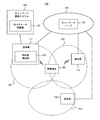
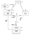
- FIG. 1 is a block diagram illustrating a configuration example of a wireless communication system 100 according to some embodiments including the present embodiment.
- the wireless communication system 100 includes a plurality of base stations 111-113.
- Base stations 111 to 113 manage cells 131 to 133, respectively, and communicate with one or more mobile terminals (for example, mobile terminal 101).
- the mobile terminal 101 can be connected to any of the base stations 111 to 113.
- the configuration example in FIG. 1 is merely an example for explanation, and may be changed as appropriate.
- the wireless communication system 100 may include four or more base stations.
- the adjacency relationship between the cells 131 to 133 shown in FIG. 1 is merely an example.
- the wireless communication system 100 may have a hierarchical cell structure in which a certain cell (for example, the cell 132) is arranged in another cell (for example, the cell 133).
- the base stations 111 to 113 are connected to the network 140 including the network node 141 and can communicate with the network node 141.
- the network 140 includes, for example, a radio access network, a core network, or both.
- the network node 141 includes a radio access network node, a core network node, or both.
- the network node 141 may be associated with a plurality of network nodes.
- the network node 141 may be a user plane (data plane) node or a control plane node.
- the network node 141 performs, for example, at least one of radio resource management, mobility management, bearer management, user data transfer / routing, and a gateway function with an external network.
- the wireless communication system 100 also includes a handover (HO) failure detection unit 121 and an HO parameter adjustment unit 151.
- the HO failure detection unit 121 and the HO parameter adjustment unit 151 can be referred to as a system for reducing handover failures (that is, a handover optimization system).
- the HO failure detection unit 121 selects at least one of a plurality of handover failure types (for example, Too Late Handover, Too Early Handover, and Handover to Wrong Cell) related to an outbound handover from the cell 131 (base station 111). To detect. Then, the HO failure detection unit 121 generates feedback information regarding the outward handover from the source cell 131 and supplies this to the HO parameter adjustment unit 151.
- a handover failure detection unit 121 and the HO parameter adjustment unit 151 can be referred to as a system for reducing handover failures (that is, a handover optimization system).
- the HO failure detection unit 121 selects at least one of a plurality of handover failure
- the feedback information is generated based on the detection result of the handover failure type and indicates a detection history of the handover failure type.
- the feedback information may indicate the number of detections for each handover failure type and the number of handover attempts. Further, the feedback information may indicate an occurrence rate for each handover failure type.
- the HO parameter adjustment unit 151 includes at least one of the HO parameters (for example, A3-offset, CIO, and TTT). Adjust). The adjusted HO parameter is applied to the cell 131.
- the HO failure detection unit 121 is arranged integrally with the base station 111, and the HO parameter adjustment unit 151 is arranged in a network management system 150.
- the network management system 150 may also be called an OAM (Operation Administration and Maintenance) server, OMC (Operation and Maintenance Center), NM (Network Manager), or EM (Element Manager).
- OAM Operaation Administration and Maintenance
- NM Network Manager
- EM Electronic Event Manager
- these arrangements are only examples.
- the HO failure detection unit 121 may be disposed away from the base station 111 so as to be communicable with the base station 111.
- the HO parameter adjustment unit 151 may be disposed integrally with the base station 111 or may be disposed in the network 140, for example.
- the cell 131 may be referred to as a “source cell” and the cell 132 may be referred to as a “target cell”.
- the base station 111 may be referred to as a “source base station”, and the base station 112 may be referred to as a “target base station”.
- the cell 133 may be referred to as a “peripheral cell” or a “reconnection cell”.
- the base station 113 may be referred to as a “peripheral base station” or a “reconnection base station”.
- the reconnection cell means a cell (but different from both the source cell and the target cell) requested to re-establish radio connection by the mobile terminal 101 that has experienced RLF during handover or immediately after handover completion.
- the HO failure detection unit 121 observes the following (a) and (b), and thereby performs a plurality of handover failure types (for example, Too) related to the outward handover from the cell 131.
- Late Handover, Too Early Handover, and Handover to Wrong Cell are detected: (A) Regarding the first handover of the mobile terminal 101 from the source cell 131 to the target cell 132, the presence or absence of an acknowledgment of the handover instruction received by the source base station 111 from the mobile terminal 101, and (b) the first handover Whether there is a request for re-establishing a connection from the mobile terminal 101 to the source base station 111 after the start of the connection
- the HO parameter adjustment unit 151 of the present embodiment adjusts the HO parameter based on the detection result by the HO failure detection unit 121. Therefore, the HO parameter adjustment unit 151 adjusts the HO parameter for controlling the outward handover from the cell 131 according to the following (a) and (b): (A) Regarding the first handover of the mobile terminal 101 from the source cell 131 to the target cell 132, the presence or absence of an acknowledgment of the handover instruction received by the source base station 111 from the mobile terminal 101, and (b) the first handover Whether there is a request for re-establishing a connection from the mobile terminal 101 to the source base station 111 after the start of the connection
- the acknowledgment of the handover instruction may be transmitted from the mobile terminal 101 to the source base station 111 regardless of a situation where the inter-base station interface cannot be used or a situation where the inter-base station interface can be used.
- the acknowledgment of the handover instruction is a message (signal) that the source base station 111 receives from the mobile terminal 101 in the handover procedure.
- the acknowledgment of the handover instruction may be a message transmitted after the mobile terminal 101 has successfully received the handover instruction.
- the acknowledgment of the handover instruction is performed for retransmission control of the “HO Command Command” message (more specifically, “RRC Connection Connection Reconfiguration” message) transmitted from the source base station 111 to the mobile terminal 101.
- An acknowledgment (ACK) transmitted from the mobile terminal 101 to the source base station 111 may be used.
- the acknowledgment may be a signal notifying that the mobile terminal 101 has correctly received the “HO Command” message in the retransmission control by AutomaticAutoRepeat reQuest (ARQ).
- ARQ AutomaticAutoRepeat reQuest
- the acknowledgment may be a signal notifying that the mobile terminal 101 has correctly received the “HO ⁇ Command” message in the retransmission control using Hybrid ⁇ ⁇ ⁇ Automatic Repeat reQuest (HARQ).
- HARQ Hybrid ⁇ ⁇ ⁇ Automatic Repeat reQuest
- the start of handover may be associated with the source base station 111 transmitting a handover instruction to the mobile terminal 101.
- the mobile terminal 101 that has received the handover instruction starts connection to the target base station 112.
- the start of handover may be associated with the source base station 111 transmitting a handover request to the target base station 112 or the network node 141 in preparation for handover.
- the target base station 112 or the network node 141 that has received the handover request starts handover preparation including radio resource setup in the target base station 112.
- the start of the handover may be associated with the source base station 111 receiving information (for example, a measurement report) that triggers the handover from the mobile terminal 101.
- the start of handover may be associated with transmission of a “HO Command” message from the source base station 111 to the mobile terminal 101.
- the start of handover may be associated with transmission of a “Handover Request” message from the source base station 111 to the target base station 112.
- the start of handover may be associated with transmission of a “HandoverHandRequired” message from the source base station 111 to the network node 141 (specifically, the MME).
- the start of handover may be associated with the source base station 111 receiving MeasurementMeasureReport from the mobile terminal 101. Note that the handover procedure including transmission / reception of the HO Command message, the Handover Request message, and the Measurement Report is defined in 3GPP TS 36.300.
- the HO failure detection unit 121 includes the above-described (a) whether or not the mobile terminal 101 has received a handover instruction acknowledgment and (b) whether or not to receive a connection re-establishment request. Based on the above, the handover failure type is detected. Therefore, the HO failure detection unit 121 has information (for example, a HANDOVER REPORT message) between at least some of the three base stations (that is, the source base station 111, the target base station 112, and the neighboring base station 113). In addition, it is possible to improve handover failure detection in a situation where the exchange of (and RLF (INDICATION messages)) is restricted. Further, the HO parameter adjustment unit 151 can contribute to the reduction of the handover failure in the situation by using the detection result of the HO failure detection unit 121.
- the HO failure detection unit 121 can detect Too Late Handover and / or Too Early Handover related to an outward handover from the source cell 131 without using information from the target base station 112 and the neighboring base station 113. Further, in another example, the HO failure detection unit 121 performs handover Wrong Cell related to the outward handover from the source cell 131 in a situation where information from either the target base station 112 or the neighboring base station 113 is not available. It can be detected. Note that specific examples of operations of the HO failure detection unit 121 and the HO parameter adjustment unit 151 corresponding to each handover failure type (Too Late Handover, Too Early Handover, or Handover to Wrong Cell) are described in the second to fifth embodiments. Described in.
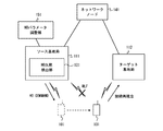
- FIG. 2 shows a situation where Too Late Handover occurs.
- information for example, a HANDOVER REPORT message and an RLF INDICATION message
- FIG. 2 assumes a situation where information (for example, a HANDOVER REPORT message and an RLF INDICATION message) cannot be transmitted and received between the source base station 111 and the target base station 112.
- This situation corresponds to, for example, a situation in which an inter-base station interface (for example, X2 interface) between the source base station 111 and the target base station 112 cannot be used.
- an inter-base station interface for example, X2 interface
- the mobile terminal 101 is connected to the source base station 111 (source cell 131) and communicates via the source base station 111.
- the mobile terminal 101 is located near the target base station 112.
- the mobile terminal 101 sends a measurement report indicating the radio quality of the source cell 131 and the target cell 132 according to a predetermined condition (for example, establishment of an aperiodic condition or establishment of a periodic condition).
- a predetermined condition for example, establishment of an aperiodic condition or establishment of a periodic condition.
- the source base station 111 determines an outward handover of the mobile terminal 101 to the target cell 132 (target base station 112), and starts this outward handover.
- target base station 112 the target base station 112
- the source base station 111 transmits a handover instruction (for example, HO Command message) to the mobile terminal 101 in order to start handover.
- a handover instruction for example, HO Command message
- the start of handover may be associated with transmission of a handover request (for example, Handover Required message) from the source base station 111 to the network node 141 (for example, MME).
- the start of handover may be associated with reception by the source base station 111 of information (for example, Measurement Report) that triggers handover.
- the mobile terminal 101 of FIG. 2 experiences RLF in the source cell 131 (source base station 111) before the handover to the target cell 132 is completed. Then, the mobile terminal 101 tries to reestablish connection to the target cell 132. In other words, the mobile terminal 101 transmits a connection re-establishment request to the target base station 112.
- the HO failure detection unit 121 receives an acknowledgment from the mobile terminal 101 in response to the handover instruction related to the outward handover within a predetermined period T1 depending on the start of the outward handover to the target cell 132. Too Late Handover may be detected when no connection reestablishment request from the mobile terminal 101 to the source cell 131 is received within a predetermined period T1. It should be noted that the predetermined period for determining whether or not the handover instruction has been acknowledged may be different from the predetermined period for determining whether or not to receive a connection re-establishment request.
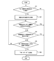
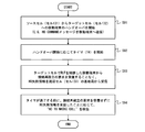
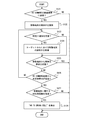
- FIG. 3 is a flowchart showing a first example of the Too Late Handover detection procedure.
- the source base station 111 starts handover of the mobile terminal 101 from the source cell 131 to the target cell 132.
- the start of handover may be transmission of a handover instruction to the mobile terminal 101, transmission of a handover request to the network node 141, or reception of information from the mobile terminal 101 that triggers handover.
- the source base station 111 starts a timer for measuring the predetermined period T1 in response to the start of handover.
- step S13 the source base station 111 (that is, the HO failure detection unit 121) responds to the fact that neither the handover instruction acknowledgment nor the connection re-establishment request is received from the mobile terminal 101 before the timer expires. It detects that the attempted handover for the mobile terminal 101 is Too Late Handover.
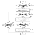
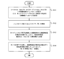
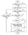
- FIG. 4 is a flowchart showing a second example of the Too Late Handover detection procedure.
- the HO failure detection unit 121 determines whether a handover instruction (for example, a HO command message) is transmitted from the source cell 131 (source base station 111) to the mobile terminal 101.
- the handover instruction is transmitted (YES in step S21)
- the HO failure detection unit 121 acquires and holds the identifier (for example, C-RNTI) of the mobile terminal 101 (that is, the transmission destination of the handover instruction) (step S21).
- the HO failure detection unit 121 determines whether an acknowledgment of a handover instruction related to the outward handover of the mobile terminal 101 has been received.
- the HO failure detection unit 121 determines whether a connection re-establishment request from the mobile terminal 101 to the source cell 131 has been received (step S24). When neither the handover instruction acknowledgment nor the re-establishment request is received (NO in step S24), the HO failure detection unit 121 determines whether a predetermined period T1 has elapsed since the transmission of the handover instruction (for example, the HO Command message). (Step S25). When the predetermined period T1 has elapsed (YES in step S25), the HO failure detection unit 121 detects that the attempted handover for the mobile terminal 101 is TooToLate Handover (step S26).
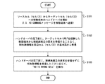
- FIG. 5 is a flowchart showing an example of the HO parameter adjustment procedure by the HO parameter adjustment unit 151.
- the HO parameter adjustment unit 151 calculates the occurrence rate R_TL of Too Late Handover related to the handover from the source cell 131 to the target cell 132 based on the feedback information received from the HO failure detection unit 121.
- the feedback information includes, for example, handover statistical information such as the number of detected Too Late Handovers and the number of handover attempts for each neighboring cell including the target cell 132.
- the occurrence rate R_TL of Too Late Handover may be a value obtained by dividing the number of detected Too Late Handover by the number of attempts of outward handover from the source cell 131.
- the HO parameter adjustment unit 151 adjusts the HO parameter to reduce Too Late Handover in response to the occurrence rate R_TL of Too Late Handover being larger than a predetermined threshold R_TH1 (steps S32 and S33).
- the CIO that affects the radio quality of the target cell 132 may be increased by a predetermined step size.
- the TTT applied to the source cell 131 may be reduced by a predetermined step size.
- A3-offset that affects the radio quality of the source cell 131 may be reduced by a predetermined step size.
- the HO failure detection unit 121 detects TooToLate Handover without receiving information (for example, HANDOVER ⁇ ⁇ ⁇ REPORT message and RLF INDICATION message) from the target base station 112. it can. Further, the HO parameter adjustment unit 151 can adjust the HO parameter for reducing Too Late Handover regardless of reception of information (for example, HANDOVER REPORT message and RLF INDICATION message) from the target base station 112.
- the Too Late Handover detected by the method described in this embodiment may include a part of the Handover to Wrong Cell.
- the method described in the present embodiment cannot identify a part of Too Late Handover and Handover Wrong Cell.
- a part of these Handover Wrong Cells can be reduced by adjusting the HO parameters similar to Too Late Handover (for example, reduction of A3-offset applied to the source cell 131).
- a handover failure including Handover to Wrong Cell can be appropriately reduced even if a part of Handover to Wrong Cell cannot be strictly distinguished.
- the HO parameter adjustment unit 151 performs HO parameter adjustment for Handover-to-Wrong Cell reduction when the occurrence rate of Too-Late Handover does not decrease even after adjusting the HO parameter for Too-Late Handover reduction. Also good.
- HO parameter adjustment for Handover Wrong Cell reduction is performed in the opposite direction to adjustment of HO parameter for Too Late Handover reduction (for example, reduction of CIO affecting the radio quality of the target cell 132, source cell TTT applied to 131 or A3-offset that affects the radio quality of the source cell 131) may be performed.
- the HO parameter adjustment may increase the CIO that affects the radio quality of the peripheral cells (for example, the cell 133) of the source cell 131 excluding the target cell 132.
- the method described in this embodiment can sufficiently contribute to the reduction of the handover failure even if a part of the Handover to Wrong Cell cannot be distinguished.
- the source base station 111 can communicate with either the target base station 112 or the neighboring base station 113, it is also possible to detect a part of the Handover Wrong Cell separately from the Too Late Handover. This technique will be described in the fourth and fifth embodiments described later.
- Too Early Handover is a situation in which the mobile terminal 101 that has experienced RLF in the target cell 132 (base station 112) attempts to reestablish connection to the source cell 131 (base station 111) during the handover procedure or immediately after the handover is completed.
- base station 112 base station 112
- This situation corresponds to, for example, a situation in which an inter-base station interface (for example, X2 interface) between the source base station 111 and the target base station 112 cannot be used.
- information for example, a HANDOVER REPORT message and an RLF INDICATION message
- the mobile terminal 101 is connected to the source base station 111 (source cell 131) and communicates via the source base station 111. At the same time, the mobile terminal 101 is located near the target base station 112. Thereafter, the source base station 111 determines an outward handover of the mobile terminal 101 to the target cell 132 (target base station 112), and starts this outward handover.
- the source base station 111 transmits a handover instruction (for example, HO Command message) to the mobile terminal 101 in order to start handover.
- the start of handover may be associated with transmission of a handover request (eg, Handover-Required message) from the source base station 111 to the network node 141 (eg, MME).
- the start of handover may be associated with reception by the source base station 111 of information (for example, Measurement Report) that triggers handover.
- the source base station 111 receives a handover completion notification (for example, “UE Context Release Command” message from the MME) transmitted in response to the completion of the handover of the mobile terminal 101 to the target cell 132.
- a handover completion notification for example, “UE Context Release Command” message from the MME
- the mobile terminal 101 experiences RLF in the target cell 132.
- the mobile terminal 101 detects that the radio quality of the source cell 131 is good, and transmits a connection re-establishment request to the source cell 131 (source base station 111).
- the mobile terminal 101 may experience RLF in the target cell 132 during execution of the handover to the target cell 132.
- the HO failure detection unit 121 requests the connection re-establishment from the mobile terminal 101 to the source cell 131 (source base station 111) within a predetermined period T2 depending on the start of the outward handover of the mobile terminal 101. May be detected when Too Early ⁇ ⁇ Handover is received.
- the HO failure detection unit 121 receives the source cell 131 (source base station) from the mobile terminal 101 after the outward handover of the mobile terminal 101 is started and before the handover is completed (for example, before the handover completion notification is received).
- Too Early Handover may be detected when a connection re-establishment request to the station 111) is received. Further, as a third example, the HO failure detection unit 121 transmits the mobile terminal 101 to the source cell 131 (source base station 111) within a predetermined period T3 depending on completion of handover (for example, reception of handover completion notification). Too Early Handover may be detected when a connection re-establishment request is received.
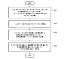
- FIG. 7 is a flowchart showing a first example of the Too Early Handover detection procedure.
- the source base station 111 starts handover of the mobile terminal 101 from the source cell 131 to the target cell 132.
- the start of handover may be transmission of a handover instruction to the mobile terminal 101, transmission of a handover request to the network node 141, or reception of information from the mobile terminal 101 that triggers handover.
- the source base station 111 starts a timer for measuring the predetermined period T2 in response to the start of handover.
- the source base station 111 receives a connection re-establishment request from the mobile terminal 101 that has experienced RLF in the target cell 132.
- step S44 the source base station 111 (that is, the HO failure detection unit 121) determines that the connection re-establishment event of the mobile terminal 101 has occurred in the source cell 131 (source base station 111) before the timer expires. It detects that the attempted handover for the mobile terminal 101 is Too Early Handover.
- FIG. 8 is a flowchart showing a second example of the Too Early Handover detection procedure.
- Step S51 is the same as step S41 of FIG. That is, in step S51, the source base station 111 starts handover of the mobile terminal 101 from the source cell 131 to the target cell 132.
- step S ⁇ b> 52 the source base station 111 receives a connection re-establishment request from the mobile terminal 101 that has experienced RLF in the target cell 132 after starting and before completing the outward handover of the mobile terminal 101.
- step S53 the source base station 111 (that is, the HO failure detection unit 121) receives a connection re-establishment request from the mobile terminal 101 after the start of the outward handover of the mobile terminal 101 and before the completion thereof. , It detects that the attempted handover for the mobile terminal 101 is Too Early Handover.
- FIG. 9 is a flowchart showing a third example of the Too Early Handover detection procedure.
- the handover of the mobile terminal 101 from the source cell 131 to the target cell 132 is completed.
- the source base station 111 receives a handover completion notification (for example, UE Context Release Command message) from the network node 141.
- the source base station 111 starts a timer for measuring the predetermined period T3 in response to completion of the handover.
- the source base station 111 receives a connection re-establishment request from the mobile terminal 101 that has experienced RLF in the target cell 132.
- step S64 the source base station 111 (that is, the HO failure detection unit 121) determines that the connection re-establishment event of the mobile terminal 101 has occurred in the source cell 131 (source base station 111) before the timer expires. It detects that the attempted handover for the mobile terminal 101 is Too Early Handover.
- FIG. 10 is a flowchart showing a fourth example of the Too Early Handover detection procedure.
- the HO failure detection unit 121 determines whether a handover instruction (for example, a HO command message) is transmitted from the source cell 131 (source base station 111) to the mobile terminal 101.
- the handover instruction is transmitted (YES in step S21)
- the HO failure detection unit 121 acquires and holds the identifier (for example, C-RNTI) of the mobile terminal 101 (that is, the transmission destination of the handover instruction) (step S21).
- the HO failure detection unit 121 determines whether a handover completion notification related to the outward handover of the mobile terminal 101 has been received.
- the HO failure detection unit 121 acquires and holds the identifier (for example, C-RNTI) of the mobile terminal 101 in the target cell 132 (step S74).
- the identifier of the mobile terminal 101 in the target cell 132 (that is, the identifier assigned to the mobile terminal 101 by the target cell 132) is, for example, a handover instruction (for example, HO received) from the network node 141 by the source base station 111 immediately before step S71. It can be obtained by referring to the (Command message).
- step S75 the HO failure detection unit 121 determines whether a connection re-establishment request from the mobile terminal 101 to the source cell 131 has been received.
- the connection re-establishment request is received (YES in step S75)
- the HO failure detection unit 121 detects that the attempted handover for the mobile terminal 101 is Too Early Handover (step S76).
- the HO failure detection unit 121 determines whether to receive the connection re-establishment request until the predetermined period T2 elapses from the start of the handover. Repeat (step S77).
- step S75 the identifier held in step S72 or S74 is connected in order to determine the identity of the mobile terminal that attempted the outward handover to the target cell 132 and the source mobile terminal of the connection re-establishment request. What is necessary is just to collate with the identifier contained in the re-establishment request. As can be understood from this, steps S73 and S74 are performed in order to change the terminal identifier collated with the connection re-establishment request before and after the completion of the handover. Therefore, when a terminal identifier that does not change before and after the completion of handover can be used for collation, the processes of steps S73 and S74 may be omitted.
- FIG. 11 is a flowchart showing an example of the HO parameter adjustment procedure by the HO parameter adjustment unit 151.
- the HO parameter adjustment unit 151 adjusts the HO parameter according to the detection of Too Late Handover and Too Early Handover. Too Late Handover may be detected according to the second embodiment described above.
- the HO parameter adjustment unit 151 calculates the occurrence rate R_TL of Too Late Handover related to the handover from the source cell 131 to the target cell 132, as in step S31 of FIG.
- step S ⁇ b> 82 the HO parameter adjustment unit 151 calculates an occurrence rate R_TE of Too Early Handover related to the handover from the source cell 131 to the target cell 132 based on the feedback information received from the HO failure detection unit 121.
- the feedback information includes, for example, handover statistical information such as the number of detected Too Late Handover, the number of detected Too Early Handover, and the number of handover attempts for each neighboring cell including the target cell 132.
- the occurrence rate R_TE of Too Early Handover may be a value obtained by dividing the number of detected Too Early Handover by the number of outbound handover attempts from the source cell 131.
- the HO parameter adjustment unit 151 adjusts the HO parameter according to the sum of R_TL and R_TE being larger than the predetermined threshold value R_TH2 (step S83). Specifically, when the occurrence rate R_TL of Too Late Handover is larger than the occurrence rate R_TE of Too Early Handover (YES in step S84), HO parameter adjustment for reducing Too Late Handover is performed (step S85). On the other hand, when the occurrence rate R_TE of ToooverEarly Handover is equal to or higher than the occurrence rate R_TL of Too Late Handover (NO in step S84), HO parameter adjustment for reducing Too Early Handover is performed (step S86).
- the CIO that affects the radio quality of the target cell 132 may be reduced by a predetermined step size. Further, the TTT applied to the source cell 131 may be increased by a predetermined step size. Further, A3-offset that affects the radio quality of the source cell 131 may be increased by a predetermined step size. In step S85, an adjustment for increasing or decreasing the HO parameter in the direction opposite to that in step S86 may be performed.
- the HO failure detection unit 121 detects TooToEarly Handover without receiving information (for example, HANDOVER REPORT message and RLF INDICATION message) from the target base station 112. it can. Further, the HO parameter adjustment unit 151 can adjust the HO parameter for reducing Too Early Handover regardless of reception of information (for example, HANDOVER REPORT message and RLF INDICATION message) from the target base station 112.
- FIG. 12 shows a situation where Handover to Wrong Cell occurs.
- the target base station 112 cannot send and receive information (for example, a HANDOVER REPORT message and an RLF INDICATION message) to and from the other two base stations (ie, the source base station 111 and the neighboring base station 113). Is assumed.
- the source base station 111 can communicate with the neighboring base station 113 and receives handover (HO) failure information from the neighboring base station 113.
- the HO failure information may be transmitted through an inter-base station interface (for example, an X2 interface) between the source base station 111 and the peripheral base station 113, or may be transmitted through the network 140.
- the mobile terminal 101 is connected to the source base station 111 (source cell 131) and communicates via the source base station 111. At the same time, the mobile terminal 101 is located near the target base station 112 and the neighboring base station 113. Thereafter, the source base station 111 determines an outward handover of the mobile terminal 101 to the target cell 132 (target base station 112), and starts this outward handover. In the example of FIG. 12, the source base station 111 transmits a handover instruction (for example, HO Command message) to the mobile terminal 101 in order to start handover.
- a handover instruction for example, HO Command message
- the start of handover may be associated with transmission of a handover request (eg, Handover-Required message) from the source base station 111 to the network node 141 (eg, MME).
- a handover request eg, Handover-Required message
- the start of handover may be associated with reception by the source base station 111 of information (for example, Measurement Report) that triggers handover.
- the source base station 111 receives a handover completion notification (for example, “UE Context Release Command” message from the MME) transmitted in response to the completion of the handover of the mobile terminal 101 to the target cell 132.
- a handover completion notification for example, “UE Context Release Command” message from the MME
- the mobile terminal 101 experiences RLF in the target cell 132.
- the mobile terminal 101 detects that the wireless quality of the neighboring cell 133 is good, and transmits a connection re-establishment request to the neighboring cell 133 (the neighboring base station 113).
- the mobile terminal 101 may experience RLF in the target cell 132 during execution of the handover to the target cell 132.
- the handover completion notification shown in FIG. 12 is transmitted to the source base station 111.
- the source base station 111 and the neighboring base station 113 in FIG. 12 perform a process of detecting a Handover to Wrong cell without receiving information (for example, a HANDOVER REPORT message and an RLF INDICATION message) from the target base station 112. .
- the HO failure detection unit 121 uses the HO failure information notified from the neighboring base station 113 for detecting Handover-> Wrong-Cell.
- the HO failure detection unit 121 receives (a) a request for reestablishing a connection from the mobile terminal 101 to the source cell 131 within a predetermined period T4 depending on the start of the outward handover of the mobile terminal 101. And (b) even if Handover Wrong Cell is detected in response to receiving HO failure information indicating that the mobile terminal 101 has requested the neighboring cell 133 to reestablish connection within a predetermined period T4. Good.
- the predetermined period for determining the timing when the mobile terminal 101 requests connection re-establishment to the neighboring cell 133 may be different from the predetermined period for determining reception of the re-establishment request to the source cell 131.
- the HO failure detection unit 121 (a) a request for reestablishing a connection from the mobile terminal 101 to the source cell 131 is received after the start of the outward handover of the mobile terminal 101 and before the completion of the handover (for example, In response to receiving HO failure information indicating that the mobile terminal 101 has not received before handover completion notification and (b) the mobile terminal 101 has requested the neighboring cell 133 to reestablish connection before handover completion. You may detect to Wrong Cell.
- the HO failure detection unit 121 (a) requests for re-establishment of connection from the mobile terminal 101 to the source cell 131 within a predetermined period T5 depending on completion of the outward handover of the mobile terminal 101. And (b) HO failure information indicating that the mobile terminal 101 has requested connection re-establishment to the neighboring cell 133 within a predetermined period T5 is detected. May be.
- the predetermined period for determining the timing when the mobile terminal 101 requests connection re-establishment to the neighboring cell 133 may be different from the predetermined period for determining reception of the re-establishment request to the source cell 131.
- the HO failure detection unit 121 sets the Handover Wrong Cell based on whether or not the HO failure information is received within a predetermined period. It may be detected. For example, in the first example described above, the HO failure detection unit 121 does not receive a connection re-establishment request from the mobile terminal 101 to the source cell 131 within the predetermined period T4, and the HO failure information is within the predetermined period T4. May be detected in response to the received signal.
- the HO failure detection unit 121 receives a request for reestablishing a connection from the mobile terminal 101 to the source cell 131 after the start of the outward handover of the mobile terminal 101 and before the completion of the handover. In response to receiving the HO failure information without fail, Handover to Wrong Cell may be detected. In the third example described above, the HO failure detection unit 121 does not receive a connection re-establishment request from the mobile terminal 101 to the source cell 131 within the predetermined period T5, and receives HO failure information within the predetermined period T5. In response to this, Handover Wrong Cell may be detected. Also in these modified examples, the predetermined period for determining reception of the HO failure information may be a time different from the predetermined period for determining reception of the re-establishment request to the source cell 131.
- the HO failure information generation unit 123 arranged in the peripheral base station 113 generates HO failure information without receiving information from the target base station 112 and notifies the source base station 111 of this.
- the HO failure information may include the following information: An identifier (eg, PCI) of the source cell (ie, cell 131) of the handover failure; An identifier (eg, PCI) of the target cell (ie, cell 132) of the handover failure; The identifier (eg, PCI) of the cell (ie, cell 133) that the mobile terminal 101 attempted to re-establish connection after RLF in the target cell, and the identifier (eg, C ⁇ ) of the mobile terminal 101 that experienced RLF in the target cell RNTI).
- the source base station 111 may be notified including ECGI instead of PCI.
- the HO failure information generation unit 122 determines whether or not there is a source base station that has requested the mobile terminal 101 to perform handover to the target cell 132 within a predetermined period before connection re-establishment in the neighboring cell 133 of the mobile terminal 101. It may be detected. And when a source base station is detected, HO failure information should just be transmitted with respect to the source base station. In other words, the HO failure information may be transmitted when the handover of the mobile terminal 101 is started within a predetermined period before the connection re-establishment in the peripheral cell 133 of the mobile terminal 101.
- the HO failure information generation unit 122 makes an inquiry to one or a plurality of peripheral base stations (including the base station 111) that can communicate with the peripheral base station 113. By doing so, the source base station may be searched. For example, the HO failure information generation unit 122 may make an inquiry to a base station that manages a cell that can be handed over from the neighboring cell 133 (a cell registered in the e.g. neighbor cell list). Further, the HO failure information generation unit 122 may receive the movement history of the mobile terminal 101 from the mobile terminal 101. The movement history may indicate a base station to which the mobile terminal 101 has connected in the past and a handover history. The history may be transmitted from the mobile terminal 101 to the base station 113 when requesting connection re-establishment.
- FIG. 13 is a flowchart showing a first example of a HandoverHandWrong Cell detection procedure.
- the source base station 111 starts handover of the mobile terminal 101 from the source cell 131 to the target cell 132.
- the start of handover may be transmission of a handover instruction to the mobile terminal 101, transmission of a handover request to the network node 141, or reception of information from the mobile terminal 101 that triggers handover.
- the source base station 111 starts a timer for measuring the predetermined period T4 in response to the start of handover.
- step S93 the source base station 111 receives HO failure information from the neighboring base station 113 without receiving a connection re-establishment request from the mobile terminal 101 that has experienced RLF in the target cell 132.
- step S94 the source base station 111 (that is, the HO failure detection unit 121) has received the HO failure information from the neighboring base station 113 without receiving a connection re-establishment request to the source cell 131 before the timer expires. Accordingly, it is detected that the attempted handover for the mobile terminal 101 is a Handover-> Wrong-> Cell. That is, the HO failure detection unit 121 detects that the appropriate handover destination of the mobile terminal 101 is the neighboring cell 133.
- FIG. 14 is a flowchart showing a second example of the Handover Wrong Cell detection procedure.
- Step S101 is the same as step S91 of FIG. That is, in step S101, the source base station 111 starts handover of the mobile terminal 101 from the source cell 131 to the target cell 132.
- step S102 the source base station 111 does not receive a connection re-establishment request from the mobile terminal 101 that has experienced RLF in the target cell 132 before and after the start of the outward handover of the mobile terminal 101. Failure information is received from the neighboring base station 113.
- step S103 the source base station 111 (that is, the HO failure detection unit 121) does not receive a connection re-establishment request to the source cell 131 after the start of the outward handover of the mobile terminal 101 and before the completion thereof. In response to receiving the HO failure information from the neighboring base station 113, it detects that the outward handover of the mobile terminal 101 is a Handover-> Wrong-Cell.
- FIG. 15 is a flowchart showing a third example of the Handover Wrong Cell detection procedure.
- step S111 the handover of the mobile terminal 101 from the source cell 131 to the target cell 132 is completed.
- the source base station 111 receives a handover completion notification (for example, UE Context Release Command message) from the network node 141.
- step S112 the source base station 111 starts a timer for measuring the predetermined period T5 in response to the completion of the handover.
- the source base station 111 receives HO failure information from the neighboring base station 113 without receiving a connection re-establishment request from the mobile terminal 101 that has experienced RLF in the target cell 132.
- step S114 the source base station 111 (that is, the HO failure detection unit 121) has received the HO failure information from the neighboring base station 113 without receiving a connection re-establishment request to the source cell 131 before the timer expires. Accordingly, it is detected that the attempted handover for the mobile terminal 101 is a Handover-> Wrong-> Cell.
- FIG. 16 is a flowchart showing a fourth example of the procedure for detecting Handover Wrong Cell.
- the processing in steps S121 to S124 in FIG. 16 may be the same as the processing in steps S71 to S74 shown in FIG.
- the HO failure detection unit 121 determines whether a connection re-establishment request from the mobile terminal 101 to the source cell 131 has been received. When the connection re-establishment request is not received (NO in step S125), the HO failure detection unit 121 repeats reception determination of the connection re-establishment request until the predetermined period T4 elapses from the start of the handover (step S126). ).
- the HO failure detection unit 121 receives the HO failure information regarding the mobile terminal 101 from the neighboring base station 113. It is determined whether it has been done (step S127). More specifically, in step S127, the HO failure detection unit 121 determines whether the mobile terminal 101 has received HO failure information indicating that the neighboring cell 133 has requested connection re-establishment within a predetermined period T4. Good. When the HO failure information related to the mobile terminal 101 is received (YES in step S127), the HO failure detection unit 121 detects that the attempted handover for the mobile terminal 101 is a Handover-> Wrong-Cell (step S128).
- FIG. 17 is a flowchart showing a first example of a handover failure information notification procedure.
- the neighboring base station 113 receives a request for re-establishing connection to the neighboring cell 133 from the mobile terminal 101. This connection re-establishment request indicates that the mobile terminal 101 has experienced RLF in the target cell 132.
- the HO failure information generation unit 122 requests the mobile terminal 101 to perform handover to the target cell 132 within a predetermined period before receiving the connection re-establishment of the mobile terminal 101 (source base station). Is detected.
- the HO failure information generation unit 122 notifies the detected source base station of handover failure information.
- FIG. 18 is a flowchart showing a second example of the handover failure information notification procedure.
- the HO failure information generation unit 122 determines whether a connection reestablishment request from the mobile terminal 101 to the neighboring cell 133 has been received.
- the HO failure information generation unit 122 acquires and holds the identifier (for example, PCI) of the cell (cell A) in which the mobile terminal 101 has just stayed. To do.
- the identifier of cell A may be included in the connection re-establishment request.
- step S143 the HO failure information generating unit 122 requests the source cell (to which the handover of the mobile terminal 101 is requested from the cell A within a predetermined period before the connection re-establishment of the mobile terminal (or before the reception of the re-establishment request) Search for cell B). If the cell B is found (YES in step S144), the HO failure information generation unit 122 notifies the cell B of the HO failure information. In the example of FIG. 12, the cell B corresponds to the source cell 131.
- FIG. 19 is a flowchart showing an example of the HO parameter adjustment procedure by the HO parameter adjustment unit 151.
- the HO parameter adjustment unit 151 adjusts the HO parameter in response to detection of Too Late Handover, Too Early Handover, and Handover to Wrong Cell. Too Late Handover and Too Early Handover may be detected according to the second and third embodiments described above.
- Steps S151 and 152 the HO parameter adjustment unit 151, like Steps S81 and S82 of FIG. 11, the Too Late Handover occurrence rate R_TL and the Too Early Handover occurrence rate related to the handover from the source cell 131 to the target cell 132. R_TE is calculated.
- step S153 based on the feedback information received from the HO failure detection unit 121, the HO parameter adjustment unit 151 calculates an occurrence rate R_WCF of Handover-to-Wrong-Cell-F with the cell 132 as an inappropriate target cell.
- step S154 the HO parameter adjustment unit 151 calculates a Handover-> Wrong-Cell-R occurrence rate R_WCR in which the cell 132 is a reconnected cell (that is, a true target cell).
- the HO parameter adjustment unit 151 adjusts the HO parameter according to the sum of R_TL, R_TE, R_WCF, and R_WCR being larger than a predetermined threshold value R_TH3 (step S155). Specifically, if (R_TL + R_WCR) is greater than (R_TE + R_WCF) (YES in step S156), HO parameter adjustment is performed to reduce Too Late Handover and Handover toWrong Cell-R to cell 132 (step S157). ).
- step S156 HO parameter adjustment is performed to reduce Too Early Handover and Handover Wrong Cell-F to the cell 132 (step S156).
- step S158 the CIO that affects the radio quality of the cell 132 may be reduced by a predetermined step size.
- the TTT applied to the cell 131 may be increased by a predetermined step size.
- A3-offset that affects the radio quality of the cell 131 may be increased by a predetermined step size.
- step S157 adjustment to increase or decrease the HO parameter in a direction opposite to that in step S158 may be performed.
- the HO failure detection unit 121 and the HO failure information generation unit 122 are configured so that the source base station 111 and the neighboring base station 113 receive information from the target base station 112 (for example, HANDOVER In a situation where the REPORT message and the RLF (INDICATION message) cannot be received, the Handover to Wrong Cell can be detected.
- This Handover toWrong Cell means that the target cell 132 is an inappropriate target cell, and the cell 133 belonging to the neighboring base station 113 is a reconnection cell (that is, a true target cell).
- the HO parameter adjustment unit 151 can adjust the HO parameter for reducing Handover-> Wrong-Cell in the same situation.
- ⁇ Fifth Embodiment> detection of Handover to Wrong Cell related to handover from the source cell 131 to the target cell 132 will be described.
- the target base station 112 cannot transmit and receive information to and from the other two base stations (source base station 111 and peripheral base station 113) has been described.
- this embodiment demonstrates the example in which the surrounding base station 113 cannot transmit / receive information between two other base stations (source base station 111, target base station 112).
- a configuration example of the wireless communication system 100 according to the present embodiment may be the same as that in FIG.
- FIG. 20 shows a situation where a Handover Wrong Cell occurs.
- the neighboring base station 113 cannot transmit / receive information (for example, a HANDOVER REPORT message and an RLF INDICATION message) to and from the other two base stations (source base station 111 and target base station 112).
- the source base station 111 can communicate with the target base station 112 and receives handover (HO) failure information from the target base station 112.
- the HO failure information may be transmitted by an inter-base station interface (for example, an X2 interface) between the source base station 111 and the target base station 112, or may be transmitted via the network 140.
- an inter-base station interface for example, an X2 interface
- the mobile terminal 101 is connected to the source base station 111 (source cell 131) and communicates via the source base station 111. At the same time, the mobile terminal 101 is located near the target base station 112 and the neighboring base station 113. Thereafter, the source base station 111 determines an outward handover of the mobile terminal 101 to the target cell 132 (target base station 112), and starts this outward handover.
- the source base station 111 transmits a handover instruction (for example, HO Command message) to the mobile terminal 101 in order to start handover.
- the start of handover may be associated with transmission of a handover request (for example, a Handover request message) from the source base station 111 to the target base station 112.
- the start of handover may be associated with reception by the source base station 111 of information (for example, Measurement Report) that triggers handover.
- the source base station 111 receives a handover completion notification (for example, a “UE” Context “Release” message) transmitted in response to the completion of the handover of the mobile terminal 101 to the target cell 132.
- a handover completion notification for example, a “UE” Context “Release” message
- the mobile terminal 101 experiences RLF in the target cell 132.
- the mobile terminal 101 detects that the wireless quality of the neighboring cell 133 is good, and transmits a connection re-establishment request to the neighboring cell 133 (the neighboring base station 113).
- the mobile terminal 101 may experience RLF in the target cell 132 during execution of the handover to the target cell 132.
- the handover completion notification illustrated in FIG. 20 is transmitted to the source base station 111.
- the source base station 111 and the target base station 112 in FIG. 20 receive information (for example, a HANDOVER REPORT message and an RLF INDICATION message) from the peripheral base station 113 that manages the peripheral cell 133 (that is, the true target cell) to which the mobile terminal 101 has reconnected. ) Are received in a coordinated manner without receiving ().
- the HO failure detection unit 121 arranged in the source base station 111 uses the HO failure information notified from the target base station 112 for Handover to Wrong Cell detection.
- a specific example of the detection method by the HO failure detection unit 121 may be the same as the first to third examples described in the fourth embodiment except that the transmission source of the HO failure information is different.
- the HO failure detection unit 121 (a) a request for re-establishing a connection from the mobile terminal 101 to the source cell 131 is within a predetermined period T4 that depends on the start of the outward handover of the mobile terminal 101. And (b) detecting Handover ⁇ Wrong Cell in response to receiving HO failure information indicating that the mobile terminal 101 has experienced RLF within the predetermined period T4 in the target cell 132. Good.
- the predetermined period for determining the timing at which the mobile terminal 101 experienced RLF in the target cell 132 may be a time different from the predetermined period for determining reception of the re-establishment request to the source cell 131.
- the HO failure detection unit 121 (a) a request for reestablishing a connection from the mobile terminal 101 to the source cell 131 is received after the start of the outward handover of the mobile terminal 101 and before the completion of the handover (for example, And (b) HO failure information indicating that the mobile terminal 101 has experienced RLF before the handover is completed in the target cell 132, before the handover completion notification is received. Cell may be detected.
- the HO failure detection unit 121 (a) requests for re-establishment of connection from the mobile terminal 101 to the source cell 131 within a predetermined period T5 depending on completion of the outward handover of the mobile terminal 101. And (b) even if Handover toWrong Cell is detected in response to receiving HO failure information indicating that the mobile terminal 101 has experienced RLF within the predetermined period T5 in the target cell 132. Good.
- the predetermined period for determining the timing at which the mobile terminal 101 experienced RLF in the target cell 132 may be a time different from the predetermined period for determining reception of the re-establishment request to the source cell 131.
- the HO failure detection unit 121 sets the Handover Wrong Cell based on whether or not the HO failure information is received within a predetermined period. It may be detected. For example, in the first example described above, the HO failure detection unit 121 does not receive a connection re-establishment request from the mobile terminal 101 to the source cell 131 within the predetermined period T4, and the HO failure information is within the predetermined period T4. May be detected in response to the received signal.
- the HO failure detection unit 121 receives a request for reestablishing a connection from the mobile terminal 101 to the source cell 131 after the start of the outward handover of the mobile terminal 101 and before the completion of the handover. In response to receiving the HO failure information without fail, Handover to Wrong Cell may be detected. In the third example described above, the HO failure detection unit 121 does not receive a connection re-establishment request from the mobile terminal 101 to the source cell 131 within the predetermined period T5, and receives HO failure information within the predetermined period T5. In response to this, Handover Wrong Cell may be detected. Also in these modified examples, the predetermined period for determining reception of the HO failure information may be a time different from the predetermined period for determining reception of the re-establishment request to the source cell 131.
- the HO failure information generation unit 123 arranged in the target base station 112 generates HO failure information without receiving information from the neighboring base station 113 and notifies the source base station 111 of this.
- the HO failure information may include the following information: An identifier (eg, PCI) of the source cell (ie, cell 131) of the handover failure; An identifier (eg, PCI) of the target cell (ie, cell 132) of the handover failure; An identifier (eg, PCI) of a cell (ie, a cell 133) that the mobile terminal 101 attempts to reestablish connection after RLF in the target cell, and an identifier (eg, C ⁇ ) of the mobile terminal 101 that has experienced RLF in the target cell RNTI).
- the source base station 111 may be notified including ECGI instead of PCI.
- the HO failure information generation unit 123 may transmit the HO failure information in response to detection of loss of synchronization of the mobile terminal 101 within a predetermined period after the mobile terminal 101 is connected to the target cell 132.
- the connection of the mobile terminal 101 to the target cell 132 means that, for example, a message (for example, a “Handover Confirm” message) transmitted from the mobile terminal 101 to the target cell 132 in the handover procedure is received by the target base station 112. May be detected.
- the starting point of the predetermined period for detecting loss of synchronization can be set as appropriate.
- the starting point of the predetermined period may be the time when the handover of the mobile terminal 101 is completed.
- loss of synchronization of the mobile terminal 101 can also be expressed as abnormal disconnection (including RLF) of the connection of the mobile terminal 101.
- the loss of synchronization between the target cell 132 and the mobile terminal 101 means that, for example, the target base station 112 does not receive a response message (ACK) from the mobile terminal 101 within a predetermined period after transmitting a packet to the mobile terminal 101. May be detected as an opportunity.
- ACK response message
- the HO failure information generation unit 123 performs a process of estimating a cell that the mobile terminal 101 tries to reestablish connection when the mobile terminal 101 loses synchronization. Then, the HO failure information generation unit 123 includes the estimated cell identifier in the HO failure information. In order to estimate a cell in which the mobile terminal 101 tries to reestablish connection, the HO failure information generation unit 123 may use a measurement report received from the mobile terminal 101 by the target base station 112. The measurement report includes the measurement results of the radio quality of the target cell 132 to which the mobile terminal 101 was connected and the radio quality of neighboring cells (cell 131, cell 133, etc.).
- the mobile terminal 101 generally selects a cell with the best radio quality and attempts to reestablish connection to the cell. Therefore, a neighboring cell that shows the best radio quality except for the target cell 132 in the measurement report may be estimated as a cell for which connection re-establishment is attempted. Further, the HO failure information generation unit 123 may include, in the HO failure information, identifiers of a plurality of cells having relatively good radio quality among the cells included in the measurement report.
- the measurement report trigger condition may be set so that the measurement report from the mobile terminal 101 to the target cell 132 is performed immediately before abnormal disconnection (or loss of synchronization).
- the measurement report trigger condition may be that the radio quality (Qs) of the target cell 132 connected to the mobile terminal 101 and the radio quality (Qn) of the neighboring cells satisfy the following equation (2).
- Qs ⁇ Q_th1 and Qn> Q_th2 (2)
- Q_th1 is a threshold value for Qs
- Q_th2 is a threshold value for Qn.
- the trigger condition such as the formula (2) is defined in 3GPP TS 36.331, for example.
- the radio quality for example, RSRP (Reference Signal Received Power) or RSRQ (Reference Signal Received Quality) defined in 3GPP TS 36.214 can be used.
- RSRP Reference Signal Received Power
- RSRQ Reference Signal Received Quality
- steps S161 to S164 in FIG. 21 correspond to steps S91 to S94 in FIG.
- steps S171 to S173 in FIG. 22 correspond to steps S101 to S103 in FIG. 14, respectively.
- steps S181 to S184 in FIG. 23 correspond to steps S111 to S114 in FIG. 15, respectively.
- the source of the HO failure information is the target base station 112 in step S163.
- FIG. 24 is a flowchart illustrating a first example of a handover failure information notification procedure according to this embodiment.
- the handover of the mobile terminal 101 from the source cell 131 to the target cell 132 is completed.
- the target base station 112 transmits a handover completion notification (e.g. UE Context Release message) to the source base station 111.
- the HO failure information generation unit 123 detects loss of synchronization of the mobile terminal 101 within a predetermined period after the handover of the mobile terminal 101 to the target cell 132 is completed.
- the HO failure information generation unit 123 estimates a cell from which the mobile terminal 101 requests re-establishment based on the measurement report received from the mobile terminal 101.
- the HO failure information generation unit 123 may select a cell with the best radio quality in the measurement report. In step S194, the HO failure information generation unit 123 notifies the source base station 111 (that is, the HO failure detection unit 121) of the HO failure information.
- FIG. 25 is a flowchart showing a second example of the handover failure information notification procedure in the present embodiment.
- the target base station 112 determines whether the mobile terminal 101 has connected to the target cell 132. The connection of the mobile terminal 101 to the cell 132 may be detected when the target base station 112 receives a message (for example, a Handover Confirm message) transmitted from the mobile terminal 101 in the handover procedure.
- the target base station 112 instructs the mobile terminal 101 to perform a measurement report.
- the HO failure information generation unit 123 determines whether or not the mobile terminal 101 has started handover.
- the target base station 112 may confirm whether or not a handover instruction (for example, a Handover command message) has been transmitted to the mobile terminal 101.
- a handover instruction for example, a Handover command message
- the HO failure information generation unit 123 continues until a predetermined time elapses after the mobile terminal 101 is connected to the target cell 132 (ie, step S201).
- the mobile terminal 101 is continuously monitored for loss of synchronization in a situation where the handover is not started (step S205).
- the HO failure information generation unit 123 checks whether there is a measurement report received from the mobile terminal 101 (step S206). If there is a measurement report that has been received from the mobile terminal 101 (YES in step S206), the HO failure information generation unit 123 refers to the measurement report and generates handover failure information indicating a cell with the best radio quality. In step S208, the HO failure information generation unit 123 notifies the source cell 131 of handover failure information.
- the HO failure detection unit 121 and the HO failure information generation unit 123 are configured so that the source base station 111 and the target base station 112 receive information from the neighboring base stations 113 (for example, HANDOVER In a situation where the REPORT message and the RLF (INDICATION message) cannot be received, the Handover to Wrong Cell can be detected.
- This Handover toWrong Cell means that the target cell 132 is an inappropriate target cell, and the cell 133 belonging to the neighboring base station 113 is a reconnection cell (that is, a true target cell).
- the HO parameter adjustment unit 151 can adjust the HO parameter for reducing Handover-> Wrong-Cell in the same situation.
- the processing performed by the HO failure detection unit 121, the HO failure information generation units 122 and 123, and the HO parameter adjustment unit 151 described in the first to fifth embodiments is a semiconductor processing apparatus including Application Specific Integrated Circuit (ASIC) It may be realized using.
- ASIC Application Specific Integrated Circuit
- These processes may be realized by causing a computer system including at least one processor (e.g. microprocessor, MPU, Digital Signal Processor (DSP)) to execute a program.
- a computer system including at least one processor (e.g. microprocessor, MPU, Digital Signal Processor (DSP)) to execute a program.
- a computer system including at least one processor (e.g. microprocessor, MPU, Digital Signal Processor (DSP)) to execute a program.
- MPU Microprocessor
- DSP Digital Signal Processor
- it includes a group of instructions for causing the computer system to execute an algorithm related to the HO failure detection unit 121 (or the HO failure information generation unit 122 or 123
- Non-transitory computer readable media include various types of tangible storage media (tangible storage medium). Examples of non-transitory computer-readable media include magnetic recording media (eg flexible disks, magnetic tapes, hard disk drives), magneto-optical recording media (eg magneto-optical discs), CD-ROMs (Read Only Memory), CD-Rs, CD-R / W, semiconductor memory (for example, mask ROM, PROM (Programmable ROM), EPROM (Erasable ROM), flash ROM, RAM (random access memory)) are included.
- the program may also be supplied to the computer by various types of temporary computer-readable media. Examples of transitory computer readable media include electrical signals, optical signals, and electromagnetic waves.
- the temporary computer-readable medium can supply the program to the computer via a wired communication path such as an electric wire and an optical fiber, or a wireless communication path.
Landscapes
- Engineering & Computer Science (AREA)
- Computer Networks & Wireless Communication (AREA)
- Signal Processing (AREA)
- Mobile Radio Communication Systems (AREA)
Abstract
Description
PS+OS<PT+OT (1)
・Failure Cell ID:接続障害の発生前に移動端末が接続していたセルの識別子(Physical Cell Identity(PCI))、
・Reestablishment Cell ID:移動端末が接続再確立を試行したセルの識別子(E-UTRAN Cell Global Identifier(ECGI))、及び
・C-RNTI:接続障害の発生前に移動端末が接続していたセルにおける移動端末の識別子(C-RNTI)。
・検出したハンドオーバ失敗の種別(すなわち、Too Early Handover 又はHandover to Wrong Cell)、
・ソースセル及びターゲットセルの識別子(ECGI)、
・接続再確立が試行されたセル(Handover to Wrong Cellの場合)、及び
・Handover cause(handover preparation中にソースセルの基地局から通知された内容)。
ソースセルの基地局は、ターゲットセル (ハンドオーバが開始されている場合)、又はソースセルとは異なるセル(ハンドオーバが開始されていない場合)からRLF INDICATIONメッセージを受信したことに応じてToo Late Handoverを検出することができる。
ターゲットセルの基地局は、移動端末の内向き(incoming)ハンドオーバが完了した後(つまり、UE CONTEXT RELEASEメッセージを送信した後)の所定期間(Tstore_UE_cntxt)内に、又は当該移動端末に関してハンドオーバの準備がされている間に、当該移動端末に関するRLF INDICATIONメッセージをソースセルから受信したことに応じてToo Early Handoverを検出できる。また、ソースセルの基地局は、Too Early Handoverを示すHANDOVER REPORTメッセージをターゲットセルの基地局から受信することによってToo Early Handoverを検出することができる。
ターゲットセルの基地局は、移動端末の内向き(incoming)ハンドオーバが完了した後(つまり、UE CONTEXT RELEASEメッセージを送信した後)の所定期間(Tstore_UE_cntxt)内に、又は当該移動端末に関してハンドオーバの準備がされている間に、当該移動端末に関するRLF INDICATIONメッセージをソースセルとは異なるセルから受信したことに応じてHandover to Wrong Cellを検出できる。また、ソースセルの基地局は、Handover to Wrong Cellを示すHANDOVER REPORTメッセージをターゲットセル基地局から受信することによってHandover to Wrong Cellを検出することができる。
図1は、本実施形態を含む幾つかの実施形態に係る無線通信システム100の構成例を示すブロック図である。無線通信システム100は、複数の基地局111~113を含む。基地局111~113は、セル131~133をそれぞれ管理し、1又は複数の移動端末(例えば移動端末101)と通信する。移動端末101は、基地局111~113のいずれにも接続できる。なお、図1の構成例は、説明のための一例に過ぎないから、適宜変更されてもよい。例えば、無線通信システム100は、4つ以上の基地局を含んでもよい。また、図1に示されたセル131~133の隣接関係も一例に過ぎない。例えば、無線通信システム100は、あるセル(例えばセル132)が他のセル(例えばセル133)内に配置された階層化セル構造を有してもよい。
(a)ソースセル131からターゲットセル132への移動端末101の第1のハンドオーバに関して、ソース基地局111が移動端末101から受信するハンドオーバ指示の肯定応答の有無、及び
(b)当該第1のハンドオーバの開始後に発生する移動端末101からソース基地局111に対する接続再確立の要求の有無。
(a)ソースセル131からターゲットセル132への移動端末101の第1のハンドオーバに関して、ソース基地局111が移動端末101から受信するハンドオーバ指示の肯定応答の有無、及び
(b)当該第1のハンドオーバの開始後に発生する移動端末101からソース基地局111に対する接続再確立の要求の有無。
本実施形態では、ソースセル131からターゲットセル132へのハンドオーバに関するToo Late Handoverの検出について説明する。本実施形態に係る無線通信システム100の構成例は図1と同様である。図2は、Too Late Handoverが発生する状況を示している。なお、図2は、ソース基地局111とターゲット基地局112の間で情報(例えば、HANDOVER REPORTメッセージ及びRLF INDICATIONメッセージ)を送受できない状況を想定している。この状況は、例えば、ソース基地局111及びターゲット基地局112の間の基地局間インタフェース(例えば、X2インタフェース)が使用できない状況に対応する。
本実施形態では、ソースセル131からターゲットセル132へのハンドオーバに関するToo Early Handoverの検出について説明する。本実施形態に係る無線通信システム100の構成例は図1と同様である。図6は、Too Early Handoverが発生する状況を示している。Too Early Handoverは、ハンドオーバ手順の実行中又はハンドオーバの完了直後にターゲットセル132(基地局112)でのRLFを経験した移動端末101がソースセル131(基地局111)に接続再確立を試みる状況に対応する。なお、図6は、ソース基地局111とターゲット基地局112の間で情報(例えば、HANDOVER REPORTメッセージ及びRLF INDICATIONメッセージ)を送受できない状況を想定している。この状況は、例えば、ソース基地局111及びターゲット基地局112の間の基地局間インタフェース(例えば、X2インタフェース)が使用できない状況に対応する。
本実施形態では、ソースセル131からターゲットセル132へのハンドオーバに関するHandover to Wrong Cellの検出について説明する。本実施形態に係る無線通信システム100の構成例は図1と同様である。図12は、Handover to Wrong Cellが発生する状況を示している。なお、図12は、ターゲット基地局112が他の2つの基地局(すなわち、ソース基地局111及び周辺基地局113)との間で情報(例えば、HANDOVER REPORTメッセージ及びRLF INDICATIONメッセージ)を送受できない状況を想定している。一方、ソース基地局111は、周辺基地局113と通信可能であり、周辺基地局113からハンドオーバ(HO)失敗情報を受信する。HO失敗情報は、ソース基地局111と周辺基地局113の間の基地局間インタフェース(例えば、X2インタフェース)によって送信されてもよいし、ネットワーク140を介して送信されてもよい。
・ハンドオーバ失敗のソースセル(すなわちセル131)の識別子(例えば、PCI)、
・ハンドオーバ失敗のターゲットセル(すなわちセル132)の識別子(例えば、PCI)、
・ターゲットセルでのRLF後に移動端末101が接続再確立を試行したセル(すなわちセル133)の識別子(例えば、PCI)、及び
・ターゲットセルでのRLFを経験した移動端末101の識別子(例えばC-RNTI)。
なお、これらのセルのECGIを特定できる場合には、PCIの代わりにECGIを含めてソース基地局111に通知してもよい。
本実施形態では、ソースセル131からターゲットセル132へのハンドオーバに関するHandover to Wrong Cellの検出について説明する。なお、上述した第4の実施形態では、ターゲット基地局112が他の2つの基地局(ソース基地局111、周辺基地局113)との間で情報送受不能である例を示した。これに対して、本実施形態は、周辺基地局113が他の2つの基地局(ソース基地局111、ターゲット基地局112)との間で情報送受不能である例について説明する。本実施形態に係る無線通信システム100の構成例は図1と同様とすればよい。
・ハンドオーバ失敗のソースセル(すなわちセル131)の識別子(例えば、PCI)、
・ハンドオーバ失敗のターゲットセル(すなわちセル132)の識別子(例えば、PCI)、
・ターゲットセルでのRLF後に移動端末101が接続再確立を試行するセル(すなわちセル133)の識別子(例えば、PCI)、及び
・ターゲットセルでのRLFを経験した移動端末101の識別子(例えばC-RNTI)。
なお、これらのセルのECGIを特定できる場合には、PCIの代わりにECGIを含めてソース基地局111に通知してもよい。
Qs < Q_th1 かつ Qn > Q_th2 (2)
ここで、Q_th1はQsに対する閾値であり、Q_th2はQnに対する閾値である。(2)式のようなトリガー条件は、例えば、3GPP TS 36.331に規定されている。無線品質の所要値に比べて厳しい値、つまり閾値Q_th1及びQ_TH2にマージン値を加えることで、異常切断の直前に測定報告が行われるように制御できる。また、無線品質としては、例えば3GPP TS 36.214に規定されているRSRP(Reference Signal Received Power)またはRSRQ(Reference Signal Received Quality)を用いることができる。
上述した第1~第5の実施形態は、適宜組み合わせて実施されてもよい。
101 移動端末
111~113 基地局
121 ハンドオーバ(HO)失敗検出部
122、123 ハンドオーバ(HO)失敗情報生成部
131~133 セル
140 ネットワーク
141 ネットワークノード
150 ネットワーク管理システム
151 ハンドオーバ(HO)パラメータ調整部
Claims (46)
- (a)第1の基地局に属する第1のセルから第2の基地局に属する第2のセルへの移動端末の第1のハンドオーバに関するハンドオーバ指示の肯定応答の前記第1の基地局による受信の有無、及び(b)前記第1のハンドオーバの開始後に発生する前記移動端末から前記第1のセルに対する接続再確立の要求の有無を観測することにより、前記第1のセルからの外向きハンドオーバに関する複数のハンドオーバ失敗種別のうち少なくとも一部を検出する検出手段を備える、
ハンドオーバ失敗検出装置。 - 前記検出手段は、前記第1のハンドオーバの開始に依存する第1の所定期間内に前記ハンドオーバ指示の肯定応答が受信されず、かつ前記第1のハンドオーバの開始に依存する第2の所定期間内に前記接続再確立の要求が受信されない場合に、第1のハンドオーバ失敗種別を検出する、請求項1に記載のハンドオーバ失敗検出装置。
- 前記検出手段は、前記第1のハンドオーバの開始に依存する第3の所定期間内に前記接続再確立の要求が受信された場合に、第2のハンドオーバ失敗種別を検出する、請求項1又は2に記載のハンドオーバ失敗検出装置。
- 前記検出手段は、前記第1のハンドオーバに関するハンドオーバ完了通知の受信より前に前記接続再確立の要求が受信された場合に、第2のハンドオーバ失敗種別を検出する、請求項1~3のいずれか1項に記載のハンドオーバ失敗検出装置。
- 前記検出手段は、前記第1のハンドオーバに関するハンドオーバ完了通知の受信に依存する第4の所定期間内に前記接続再確立の要求が受信された場合に、第2のハンドオーバ失敗種別を検出する、請求項1~4のいずれか1項に記載のハンドオーバ失敗検出装置。
- 前記ハンドオーバ完了通知は、前記第1の基地局が接続された上位ネットワークに属するネットワークノードまたは前記第2の基地局から前記第1の基地局に送信される、請求項4又は5に記載のハンドオーバ失敗検出装置。
- 前記ハンドオーバ完了通知は、ハンドオーバ手順において前記第1の基地局が受信するメッセージである、請求項4~6のいずれか1項に記載のハンドオーバ失敗検出装置。
- 前記検出手段は、前記第1のハンドオーバの開始に依存する第4の所定期間内に前記接続再確立の要求が受信されず、かつ前記第1のハンドオーバの開始に依存する第5の所定期間内に前記第2の基地局からハンドオーバ失敗情報が受信された場合に、第3のハンドオーバ失敗種別を検出するよう動作し、
前記第3のハンドオーバ失敗種別は、前記第1のハンドオーバの実行中又は前記第1のハンドオーバの完了後に前記第2のセルでの異常な接続切断を経験した前記移動端末が前記第1及び第2のセルのいずれとも異なる第3のセルに接続再確立を試みる状況に対応する、
請求項1~7のいずれか1項に記載のハンドオーバ失敗検出装置。 - 前記ハンドオーバ失敗情報は、前記第2の基地局が、前記第3のセルを管理する第3の基地局から情報を受信することなく、前記第2のセルに接続しているときの前記移動端末による無線品質の測定情報に基づいて推定した前記第3のセルの識別子を含む、
請求項8に記載のハンドオーバ失敗検出装置。 - 前記ハンドオーバ失敗情報は、前記第1のハンドオーバによる前記移動端末の前記第2のセルへの接続に依存する第6の所定期間内に前記移動端末が前記第2のセルでの異常な接続切断を経験したことに応じて送信される、請求項8又は9に記載のハンドオーバ失敗検出装置。
- 前記検出手段は、前記第1のハンドオーバの開始に依存する第4の所定期間内に前記接続再確立の要求が受信されず、かつ前記第1のハンドオーバの開始に依存する第7の所定期間内に前記第1及び第2のセルのいずれとも異なる第3のセルを管理する第3の基地局からハンドオーバ失敗情報が受信された場合に、第3のハンドオーバ失敗種別を検出するよう動作し、
前記第3のハンドオーバ失敗種別は、前記第1のハンドオーバの実行中又は前記第1のハンドオーバの完了後に前記第2のセルでの接続切断を経験した前記移動端末が前記第1及び第2のセルのいずれとも異なる第3のセルに接続再確立を試みる状況に対応する、
請求項1~7のいずれか1項に記載のハンドオーバ失敗検出装置。 - 前記ハンドオーバ失敗情報は、前記第3の基地局が、前記移動端末の前記第3のセルでの接続再確立の以前の第8の所定期間内に前記移動端末の前記第2のセルへのハンドオーバを要求した基地局が存在することを検出したことに応じて送信される、請求項11に記載のハンドオーバ失敗検出装置。
- 前記検出手段は、前記少なくとも一部のハンドオーバ失敗種別の検出結果に基づいて、前記第1のセルからのハンドオーバに関するフィードバック情報を生成する、請求項1~12のいずれか1項に記載のハンドオーバ失敗検出装置。
- 前記フィードバック情報は、前記少なくとも一部のハンドオーバ失敗種別の発生数又は発生率を示す、請求項13に記載のハンドオーバ失敗検出装置。
- 前記ハンドオーバ指示の肯定応答は、前記移動端末から前記第1の基地局に送信される、請求項1~14のいずれか1項に記載のハンドオーバ失敗検出装置。
- 前記ハンドオーバ指示の肯定応答は、ハンドオーバ手順において前記第1の基地局から前記移動端末に送信したメッセージの再送制御のために、前記移動端末が送信する肯定応答である、請求項1~15のいずれか1項に記載のハンドオーバ失敗検出装置。
- (a)第1の基地局に属する第1のセルから第2の基地局に属する第2のセルへの移動端末の第1のハンドオーバに関するハンドオーバ指示の肯定応答の前記第1の基地局による受信の有無、及び(b)前記第1のハンドオーバの開始後に発生する前記移動端末から前記第1のセルに対する接続再確立の要求の有無に応じて、前記第1のセルからの外向きハンドオーバを制御するためのハンドオーバ・パラメータを調整する調整手段を備える、
ハンドオーバ・パラメータ調整装置。 - 前記調整手段は、前記第1のセルからの外向きハンドオーバに関する複数のハンドオーバ失敗種別のうち少なくとも一部の検出結果に基づくフィードバック情報を受信し、
前記少なくとも一部のハンドオーバ失敗種別の検出結果は、前記ハンドオーバ指示の肯定応答の受信の有無、及び前記接続再確立の要求の有無の観測により得られる、
請求項17に記載のハンドオーバ・パラメータ調整装置。 - 前記調整手段は、前記フィードバック情報を解析することによって前記ハンドオーバ・パラメータを調整する、請求項18に記載のハンドオーバ・パラメータ調整装置。
- 前記調整手段は、
前記少なくとも一部のハンドオーバ失敗種別の各々を前記ハンドオーバ・パラメータの複数の調整方向のいずれかに対応づけ、
前記複数の調整方向の各々について、各調整方向に対応付けられたハンドオーバ失敗種別の発生数又は発生率の総和を求め、
前記発生数又は発生率の総和が最も大きい調整方向に前記ハンドオーバ・パラメータを調整する、
請求項18又は19に記載のハンドオーバ・パラメータ調整装置。 - 前記ハンドオーバ・パラメータは、前記第1のセルの無線品質に作用する第1のオフセット、前記第2のセルの無線品質に作用する第2のオフセット、及び前記第1のセルに接続する移動端末による測定報告の送信を起動するための保護時間のうち少なくとも1つを含む、請求項17~20のいずれか1項に記載のハンドオーバ・パラメータ調整装置。
- 第1の基地局に通知するためのハンドオーバ失敗情報を生成する生成手段を備え、
前記ハンドオーバ失敗情報は、前記第1の基地局に属する第1のセルから第2の基地局に属する第2のセルへの第1のハンドオーバの実行中又は前記第1のハンドオーバの完了後に前記第2のセルでの異常な接続切断を経験した移動端末が前記第1及び第2のセルのいずれとも異なる第3のセルに接続再確立を試みる状況に対応するハンドオーバ失敗種別を検出するために使用される、
ハンドオーバ失敗情報生成装置。 - 前記生成手段は、前記第2の基地局と結合され、
前記ハンドオーバ失敗情報は、前記生成手段が、前記第3のセルを管理する第3の基地局から情報を受信することなく、前記第2のセルに接続しているときの前記移動端末による無線品質の測定報告に基づいて推定した前記第3のセルの識別子を含む、
請求項22に記載のハンドオーバ失敗情報生成装置。 - 前記生成手段は、前記第1のハンドオーバによる前記移動端末の前記第2のセルへの接続に依存する所定期間内に前記移動端末が前記第2のセルでの異常な接続切断を経験したことに応じて、前記ハンドオーバ失敗情報を送信する、請求項23に記載のハンドオーバ失敗情報生成装置。
- 前記生成手段は、前記測定報告において無線品質が最良のセルを前記第3のセルとして推定する、請求項23又は24に記載のハンドオーバ失敗情報生成装置。
- 前記生成手段は、前記第3のセルを管理する第3の基地局と結合され、
前記生成手段は、前記移動端末の前記第3のセルでの接続再確立の以前の所定期間内に前記移動端末の前記第2のセルへのハンドオーバを要求した基地局が存在することを検出したことに応じて、前記ハンドオーバ失敗情報を送信する、請求項22に記載のハンドオーバ失敗情報生成装置。 - 前記生成手段は、前記第3のセルからハンドオーバが可能なセルを管理する基地局を対象に、前記移動端末の前記第2のセルへのハンドオーバを要求した基地局の有無を特定する、請求項26に記載のハンドオーバ失敗情報生成装置。
- (a)第1の基地局に属する第1のセルから第2の基地局に属する第2のセルへの移動端末の第1のハンドオーバに関するハンドオーバ指示の肯定応答の前記第1の基地局による受信の有無、及び(b)前記第1のハンドオーバの開始後に発生する前記移動端末から前記第1のセルに対する接続再確立の要求の有無を観測することにより、前記第1のセルからの外向きハンドオーバに関する複数のハンドオーバ失敗種別のうち少なくとも一部を検出する検出手段と、
前記少なくとも一部のハンドオーバ失敗種別の検出結果に基づいて、前記第1のセルからの外向きハンドオーバを制御するためのハンドオーバ・パラメータを調整する調整手段と、
を備える、ハンドオーバ最適化のためのシステム。 - 前記検出手段は、前記第1のハンドオーバの開始に依存する第1の所定期間内に前記ハンドオーバ指示の肯定応答が受信されず、かつ前記第1のハンドオーバの開始に依存する第2の所定期間内に前記接続再確立の要求が受信されない場合に、第1のハンドオーバ失敗種別を検出する、請求項28に記載のシステム。
- 前記検出手段は、前記第1のハンドオーバの開始に依存する第3の所定期間内に前記接続再確立の要求が受信された場合に、第2のハンドオーバ失敗種別を検出する、請求項28又は29に記載のシステム。
- 前記検出手段は、前記第1のハンドオーバに関するハンドオーバ完了通知の受信より前に前記接続再確立の要求が受信された場合に、第2のハンドオーバ失敗種別を検出する、請求項28~30のいずれか1項に記載のシステム。
- 前記検出手段は、前記第1のハンドオーバに関するハンドオーバ完了通知の受信に依存する第4の所定期間内に前記接続再確立の要求が受信された場合に、第2のハンドオーバ失敗種別を検出する、請求項28~31のいずれか1項に記載のシステム。
- ハンドオーバ失敗情報を生成して前記検出手段に通知する生成手段をさらに備え、
前記検出手段は、前記第1のハンドオーバの開始に依存する第4の所定期間内に前記接続再確立の要求が受信されず、かつ前記第1のハンドオーバの開始に依存する第5の所定期間内にハンドオーバ失敗情報が受信された場合に、第3のハンドオーバ失敗種別を検出するよう動作し、
前記第3のハンドオーバ失敗種別は、前記第1のハンドオーバの実行中又は前記第1のハンドオーバの完了後に前記第2のセルでの異常な接続切断を経験した前記移動端末が前記第1及び第2のセルのいずれとも異なる第3のセルに接続再確立を試みる状況に対応する、
請求項28~32のいずれか1項に記載のシステム。 - 前記生成手段は、前記第2の基地局と結合され、
前記ハンドオーバ失敗情報は、前記生成手段が、前記第3のセルを管理する第3の基地局から情報を受信することなく、前記第2のセルに接続しているときの前記移動端末による無線品質の測定情報に基づいて推定した前記第3のセルの識別子を含む、
請求項33に記載のシステム。 - 前記生成手段は、前記第2の基地局と結合され、
前記生成手段は、前記第1のハンドオーバによる前記移動端末の前記第2のセルへの接続に依存する第6の所定期間内に前記移動端末が前記第2のセルでの異常な接続切断を経験したことに応じて、前記ハンドオーバ失敗情報を送信する、請求項33又は34に記載のシステム。 - 前記生成手段は、前記第3のセルを管理する第3の基地局と結合され、
前記生成手段は、前記移動端末の前記第3のセルでの接続再確立の以前の第8の所定期間内に前記移動端末の前記第2のセルへのハンドオーバを要求した基地局が存在することを検出したことに応じて、前記ハンドオーバ失敗情報を送信する、請求項33に記載のシステム。 - 前記生成手段は、前記第3のセルからハンドオーバが可能なセルを管理する基地局を対象に、前記移動端末の前記第2のセルへのハンドオーバを要求した基地局の有無を特定する、請求項36に記載のシステム。
- 前記ハンドオーバ・パラメータは、前記第1のセルの無線品質に作用する第1のオフセット、前記第2のセルの無線品質に作用する第2のオフセット、及び前記第1のセルに接続する移動端末による測定報告の送信を起動するための保護時間のうち少なくとも1つを含む、請求項28~37のいずれか1項に記載のシステム。
- 前記調整手段は、前記第1のハンドオーバ失敗種別の発生率が所定値を超えるとき、前記第1のオフセットの減少、前記第2のオフセットの増加、及び前記保護時間の減少のうち少なくとも1つを実行する、請求項29を引用する請求項38に記載のシステム。
- 前記調整手段は、前記第2のハンドオーバ失敗種別の発生率が所定値を超えるとき、前記第1のオフセットの増加、前記第2のオフセットの減少、及び前記保護時間の増加のうち少なくとも1つを実行する、請求項30、31、又は32を引用する請求項38に記載のシステム。
- 前記ハンドオーバ・パラメータは、前記第2のオフセット、及び前記第3のセルの無線品質に作用する第3のオフセットを含み、
前記調整手段は、前記第3のハンドオーバ失敗種別の発生率が所定値を超えるとき、前記第2のオフセットの減らすとともに、前記第3のオフセットの増やす、
請求項33~37のいずれか1項を引用する請求項38に記載のシステム。 - 請求項1~16のいずれか1項に記載のハンドオーバ失敗検出装置を備える基地局。
- (a)第1の基地局に属する第1のセルから第2の基地局に属する第2のセルへの移動端末の第1のハンドオーバに関するハンドオーバ指示の肯定応答の前記第1の基地局による受信の有無、及び(b)前記第1のハンドオーバの開始後に発生する前記移動端末から前記第1のセルに対する接続再確立の要求の有無を観測することにより、前記第1のセルからの外向きハンドオーバに関する複数のハンドオーバ失敗種別のうち少なくとも一部を検出することを備える、
ハンドオーバ失敗検出方法。 - (a)第1の基地局に属する第1のセルから第2の基地局に属する第2のセルへの移動端末の第1のハンドオーバに関するハンドオーバ指示の肯定応答の前記第1の基地局による受信の有無、及び(b)前記第1のハンドオーバの開始後に発生する前記移動端末から前記第1のセルに対する接続再確立の要求の有無に応じて、前記第1のセルからの外向きハンドオーバを制御するためのハンドオーバ・パラメータを調整することを備える、
ハンドオーバ・パラメータ調整方法。 - ハンドオーバ失敗検出のための方法をコンピュータに行わせるためのプログラムを格納した非一時的なコンピュータ可読媒体であって、
前記方法は、(a)第1の基地局に属する第1のセルから第2の基地局に属する第2のセルへの移動端末の第1のハンドオーバに関するハンドオーバ指示の肯定応答の前記第1の基地局による受信の有無、及び(b)前記第1のハンドオーバの開始後に発生する前記移動端末から前記第1のセルに対する接続再確立の要求の有無を観測することにより、前記第1のセルからの外向きハンドオーバに関する複数のハンドオーバ失敗種別のうち少なくとも一部を検出することを含む、
コンピュータ可読媒体。 - ハンドオーバ・パラメータ調整のための方法をコンピュータに行わせるためのプログラムを格納した非一時的なコンピュータ可読媒体であって、
前記方法は、(a)第1の基地局に属する第1のセルから第2の基地局に属する第2のセルへの移動端末の第1のハンドオーバに関するハンドオーバ指示の肯定応答の前記第1の基地局による受信の有無、及び(b)前記第1のハンドオーバの開始後に発生する前記移動端末から前記第1のセルに対する接続再確立の要求の有無に応じて、前記第1のセルからの外向きハンドオーバを制御するためのハンドオーバ・パラメータを調整することを含む、
コンピュータ可読媒体。
Priority Applications (5)
| Application Number | Priority Date | Filing Date | Title |
|---|---|---|---|
| JP2014560538A JPWO2014122706A1 (ja) | 2013-02-08 | 2013-11-14 | ハンドオーバ失敗検出装置、ハンドオーバ・パラメータ調整装置、及びハンドオーバ最適化システム |
| KR1020157021351A KR101782391B1 (ko) | 2013-02-08 | 2013-11-14 | 핸드오버 실패 검출 장치, 핸드오버·파라미터 조정 장치, 및 핸드오버 최적화 시스템 |
| CN201380072677.XA CN104982066B (zh) | 2013-02-08 | 2013-11-14 | 移交失败检测设备、移交参数调整设备和移交优化系统 |
| EP13874845.4A EP2955962B1 (en) | 2013-02-08 | 2013-11-14 | Handover failure detection device, handover parameter adjustment device, and handover optimization system |
| US14/762,663 US9992812B2 (en) | 2013-02-08 | 2013-11-14 | Handover failure detection device, handover parameter adjustment device, and handover optimization system |
Applications Claiming Priority (2)
| Application Number | Priority Date | Filing Date | Title |
|---|---|---|---|
| JP2013-022846 | 2013-02-08 | ||
| JP2013022846 | 2013-02-08 |
Publications (1)
| Publication Number | Publication Date |
|---|---|
| WO2014122706A1 true WO2014122706A1 (ja) | 2014-08-14 |
Family
ID=51299322
Family Applications (1)
| Application Number | Title | Priority Date | Filing Date |
|---|---|---|---|
| PCT/JP2013/006692 Ceased WO2014122706A1 (ja) | 2013-02-08 | 2013-11-14 | ハンドオーバ失敗検出装置、ハンドオーバ・パラメータ調整装置、及びハンドオーバ最適化システム |
Country Status (6)
| Country | Link |
|---|---|
| US (1) | US9992812B2 (ja) |
| EP (1) | EP2955962B1 (ja) |
| JP (1) | JPWO2014122706A1 (ja) |
| KR (1) | KR101782391B1 (ja) |
| CN (1) | CN104982066B (ja) |
| WO (1) | WO2014122706A1 (ja) |
Cited By (5)
| Publication number | Priority date | Publication date | Assignee | Title |
|---|---|---|---|---|
| WO2016080060A1 (ja) * | 2014-11-19 | 2016-05-26 | ソニー株式会社 | 装置 |
| JP2018133719A (ja) * | 2017-02-16 | 2018-08-23 | パナソニックIpマネジメント株式会社 | 基地局及び通信方法 |
| US10225139B2 (en) | 2016-02-05 | 2019-03-05 | Electronics And Telecommunications Research Institute | Self-organizing network (SON) system and operating method of the same |
| US10827398B2 (en) | 2017-07-24 | 2020-11-03 | Electronics And Telecommunications Research Institute | Communication node for performing handover in wireless communication system and method therefor |
| WO2025169391A1 (ja) * | 2024-02-08 | 2025-08-14 | 株式会社Nttドコモ | 基地局及びネットワークノード |
Families Citing this family (27)
| Publication number | Priority date | Publication date | Assignee | Title |
|---|---|---|---|---|
| CN105264955A (zh) * | 2013-03-29 | 2016-01-20 | 日本电气株式会社 | 无线通信系统中的通信设备和切换控制方法 |
| JP2015142363A (ja) * | 2014-01-30 | 2015-08-03 | 株式会社Nttドコモ | 移動局、再接続要求方法、基地局及び再接続要求処理方法 |
| WO2015139850A1 (en) | 2014-03-21 | 2015-09-24 | Telefonaktiebolaget L M Ericsson (Publ) | Mobility robustness optimization in a cellular network |
| KR102157861B1 (ko) * | 2014-04-28 | 2020-09-21 | 삼성전자주식회사 | 무선 통신 시스템에서 접속 관리 방법 및 장치 |
| US20160112924A1 (en) * | 2014-10-15 | 2016-04-21 | Qualcomm Incorporated | Early radio link failure (rlf) declaration |
| US10524152B2 (en) * | 2015-01-22 | 2019-12-31 | Nokia Solutions And Networks Oy | Coverage hole analysis |
| JP2017060024A (ja) * | 2015-09-17 | 2017-03-23 | 富士通株式会社 | 基地局装置 |
| US10602382B2 (en) * | 2016-01-19 | 2020-03-24 | Samsung Electronics Co., Ltd. | Radio link failure processing method and apparatus therefor |
| WO2017183897A1 (ko) * | 2016-04-20 | 2017-10-26 | 한국전자통신연구원 | 핸드오버 방법 |
| US10945168B2 (en) | 2016-04-20 | 2021-03-09 | Electronics And Telecommunications Research Institute | Handover method |
| KR102447859B1 (ko) * | 2016-04-26 | 2022-09-27 | 삼성전자 주식회사 | 무선 통신 시스템에서 핸드오버를 지원하는 방법 및 장치 |
| CN107453794B (zh) * | 2016-05-31 | 2020-12-08 | 中兴通讯股份有限公司 | 信息反馈方法、装置及系统 |
| US11523319B2 (en) | 2017-01-09 | 2022-12-06 | Lg Electronics Inc. | Method for managing PDU session in wireless communication system and device for same |
| ES2925895T3 (es) * | 2017-04-14 | 2022-10-20 | Beijing Xiaomi Mobile Software Co Ltd | Método y dispositivo para conmutar células y equipo de usuario |
| US10085213B1 (en) * | 2017-05-15 | 2018-09-25 | Apple Inc. | Device, system, and method for a high power mode for a cellular connection |
| WO2019136637A1 (en) * | 2018-01-10 | 2019-07-18 | Lenovo (Beijing) Limited | Selecting a base unit in response to a handover condition being triggered |
| CN114375070B (zh) * | 2018-08-17 | 2024-11-29 | 维沃移动通信有限公司 | 连接处理方法及设备 |
| CN112585912B (zh) * | 2018-09-04 | 2022-09-09 | Oppo广东移动通信有限公司 | 一种信息传输方法及装置、终端 |
| WO2020061931A1 (zh) | 2018-09-27 | 2020-04-02 | Oppo广东移动通信有限公司 | 一种切换上报的方法、终端设备及网络设备 |
| KR102664931B1 (ko) * | 2018-10-29 | 2024-05-09 | 삼성전자주식회사 | 이동통신 시스템에서 핸드오버 성능을 개선하는 방법 및 장치 |
| KR102231597B1 (ko) * | 2018-12-28 | 2021-03-24 | 서강대학교산학협력단 | RAN-Sharing 기술이 적용된 LTE 기반 이종망 공존 환경에서 핸드오버 파라미터를 제어하는 방법 및 장치 |
| KR102887884B1 (ko) * | 2019-08-05 | 2025-11-17 | 주식회사 케이티 | 핸드오버 실패 통계를 이용하여 핸드오버 파라미터를 조절하기 위한 관리 장치 및 방법 |
| CN111836317B (zh) * | 2019-08-14 | 2022-10-18 | 维沃移动通信有限公司 | 状态信息的上报方法、终端及网络设备 |
| EP4128875A1 (en) * | 2020-03-23 | 2023-02-08 | Telefonaktiebolaget LM Ericsson (publ) | Configuring different mobility reporting trigger conditions for reliable network connectivity |
| EP4282182A4 (en) * | 2021-01-25 | 2024-12-25 | Nokia Technologies Oy | LMF-SUPPORTED MRO |
| CN116095765B (zh) * | 2021-11-08 | 2025-07-15 | 大唐移动通信设备有限公司 | 一种小区选择方法及装置 |
| CN121400008A (zh) * | 2023-07-10 | 2026-01-23 | 联想(新加坡)私人有限公司 | 感测任务切换 |
Citations (2)
| Publication number | Priority date | Publication date | Assignee | Title |
|---|---|---|---|---|
| JP2011259207A (ja) * | 2010-06-09 | 2011-12-22 | Kyocera Corp | 無線基地局及びその制御方法 |
| JP2012147258A (ja) * | 2011-01-12 | 2012-08-02 | Kddi Corp | ハンドオーバパラメータ調整装置、ハンドオーバパラメータ調整方法およびコンピュータプログラム |
Family Cites Families (9)
| Publication number | Priority date | Publication date | Assignee | Title |
|---|---|---|---|---|
| US8559298B2 (en) | 2008-06-30 | 2013-10-15 | Qualcomm Incorporated | Method and apparatus for automatic handover optimization |
| US9107133B2 (en) * | 2009-01-06 | 2015-08-11 | Qualcomm Incorporated | Adaptation of handover parameters |
| JP5078954B2 (ja) * | 2009-08-06 | 2012-11-21 | シャープ株式会社 | 移動局装置、基地局装置、無線通信システムおよび無線通信方法 |
| KR20110020398A (ko) | 2009-08-24 | 2011-03-03 | 삼성전자주식회사 | 광대역 무선통신 시스템에서 핸드오버 최적화를 위한 장치 및 방법 |
| KR20110038571A (ko) | 2009-10-08 | 2011-04-14 | 한국전자통신연구원 | 핸드오버 실패 유형 판단을 위한 서빙 기지국 |
| US9204316B2 (en) * | 2011-09-30 | 2015-12-01 | Blackberry Limited | Enhancement and improvement for hetnet deployments |
| CN103179601B (zh) * | 2011-12-23 | 2019-07-23 | 北京三星通信技术研究有限公司 | 一种检测无线链路失败或切换失败原因的方法 |
| WO2013185354A1 (en) * | 2012-06-15 | 2013-12-19 | Nokia Siemens Networks Oy | Methods, computer program products and apparatuses enabling to improve handovers in mobile communication networks |
| US9807660B2 (en) * | 2013-06-13 | 2017-10-31 | Telefonaktiebolaget Lm Ericsson (Publ) | Load sharing in a cellular radio communication system |
-
2013
- 2013-11-14 EP EP13874845.4A patent/EP2955962B1/en not_active Not-in-force
- 2013-11-14 KR KR1020157021351A patent/KR101782391B1/ko not_active Expired - Fee Related
- 2013-11-14 CN CN201380072677.XA patent/CN104982066B/zh not_active Expired - Fee Related
- 2013-11-14 US US14/762,663 patent/US9992812B2/en active Active
- 2013-11-14 WO PCT/JP2013/006692 patent/WO2014122706A1/ja not_active Ceased
- 2013-11-14 JP JP2014560538A patent/JPWO2014122706A1/ja active Pending
Patent Citations (2)
| Publication number | Priority date | Publication date | Assignee | Title |
|---|---|---|---|---|
| JP2011259207A (ja) * | 2010-06-09 | 2011-12-22 | Kyocera Corp | 無線基地局及びその制御方法 |
| JP2012147258A (ja) * | 2011-01-12 | 2012-08-02 | Kddi Corp | ハンドオーバパラメータ調整装置、ハンドオーバパラメータ調整方法およびコンピュータプログラム |
Non-Patent Citations (3)
| Title |
|---|
| FUJITSU: "Timers in MRO failure detection", 3GPP TSG-RAN WG3#75BIS R3-120641, 30 March 2012 (2012-03-30), XP050668998 * |
| SAMSUNG: "Failure Detection without the RRC Re-establishment Attempt", 3GPP TSG-RAN WG3#77 R3-121761, 17 August 2012 (2012-08-17), XP055269830 * |
| See also references of EP2955962A4 * |
Cited By (7)
| Publication number | Priority date | Publication date | Assignee | Title |
|---|---|---|---|---|
| WO2016080060A1 (ja) * | 2014-11-19 | 2016-05-26 | ソニー株式会社 | 装置 |
| US10764773B2 (en) | 2014-11-19 | 2020-09-01 | Sony Corporation | Apparatus including an acquirer to acquire a parameter for a user relating to interference cancellation and a controller to perform measurement reporting of a cell in accordance with the parameter |
| US10225139B2 (en) | 2016-02-05 | 2019-03-05 | Electronics And Telecommunications Research Institute | Self-organizing network (SON) system and operating method of the same |
| JP2018133719A (ja) * | 2017-02-16 | 2018-08-23 | パナソニックIpマネジメント株式会社 | 基地局及び通信方法 |
| US11259221B2 (en) | 2017-02-16 | 2022-02-22 | Panasonic Intellectual Property Management Co., Ltd. | Base station and communication method |
| US10827398B2 (en) | 2017-07-24 | 2020-11-03 | Electronics And Telecommunications Research Institute | Communication node for performing handover in wireless communication system and method therefor |
| WO2025169391A1 (ja) * | 2024-02-08 | 2025-08-14 | 株式会社Nttドコモ | 基地局及びネットワークノード |
Also Published As
| Publication number | Publication date |
|---|---|
| EP2955962A1 (en) | 2015-12-16 |
| US20150373772A1 (en) | 2015-12-24 |
| CN104982066B (zh) | 2019-03-15 |
| KR101782391B1 (ko) | 2017-09-27 |
| JPWO2014122706A1 (ja) | 2017-01-26 |
| KR20150106422A (ko) | 2015-09-21 |
| CN104982066A (zh) | 2015-10-14 |
| EP2955962B1 (en) | 2020-12-30 |
| EP2955962A4 (en) | 2016-12-21 |
| US9992812B2 (en) | 2018-06-05 |
Similar Documents
| Publication | Publication Date | Title |
|---|---|---|
| KR101782391B1 (ko) | 핸드오버 실패 검출 장치, 핸드오버·파라미터 조정 장치, 및 핸드오버 최적화 시스템 | |
| WO2014002320A1 (ja) | ハンドオーバ失敗検出装置、ハンドオーバ・パラメータ調整装置、及びハンドオーバ最適化システム | |
| US12261735B2 (en) | Mobility robustness in a cellular network | |
| JP5978515B2 (ja) | 無線リンク障害統計方法、関連する装置、および通信システム | |
| KR102044019B1 (ko) | 이동성 매개변수 조정 방법 및 장치 | |
| JP2016527839A (ja) | 無線リソース制御接続の方法および装置 | |
| CN110062431A (zh) | 蜂窝无线通信系统的移动台识别方法 | |
| JP2013535904A (ja) | 情報を提供するための方法、移動局装置、基地局装置及び通信装置 | |
| CN103379517A (zh) | 无线链路失败报告处理方法、异常事件统计处理方法及设备和系统 | |
| WO2023134763A1 (zh) | 信息报告方法以及用户设备 | |
| JP6899550B2 (ja) | 基地局及び通信方法 | |
| WO2014154132A1 (zh) | 一种针对无线链路失败的网络优化方法、装置及系统 | |
| JP2021520718A (ja) | 無線通信ネットワークにおける無線リンク障害管理 | |
| CN104412652A (zh) | 移交优化系统、移交优化控制设备以及移交参数调整设备 | |
| WO2012100669A1 (zh) | 一种参数处理方法及基站 | |
| CN117459944A (zh) | 由用户设备执行的方法以及用户设备 | |
| JP2025531642A (ja) | 無線デバイス、ネットワークノード、及び障害後に再確立情報を処理するためにそれらにより実行される方法 | |
| WO2024027704A1 (zh) | 切换信息报告方法以及用户设备 | |
| WO2023246770A1 (zh) | 由用户设备执行的方法以及用户设备 | |
| Watanabe et al. | Inter-eNB coordination-free algorithm for mobility robustness optimization in LTE HetNet | |
| WO2023241622A1 (zh) | 由用户设备执行的方法、用户设备以及信息报告方法 | |
| WO2024067624A1 (zh) | 信息报告方法以及用户设备 | |
| WO2024008076A1 (zh) | 切换信息报告方法以及用户设备 | |
| CN118338348A (zh) | 无线链路失败报告方法以及用户设备 |
Legal Events
| Date | Code | Title | Description |
|---|---|---|---|
| 121 | Ep: the epo has been informed by wipo that ep was designated in this application |
Ref document number: 13874845 Country of ref document: EP Kind code of ref document: A1 |
|
| ENP | Entry into the national phase |
Ref document number: 2014560538 Country of ref document: JP Kind code of ref document: A |
|
| WWE | Wipo information: entry into national phase |
Ref document number: 14762663 Country of ref document: US |
|
| WWE | Wipo information: entry into national phase |
Ref document number: 2013874845 Country of ref document: EP |
|
| ENP | Entry into the national phase |
Ref document number: 20157021351 Country of ref document: KR Kind code of ref document: A |
|
| NENP | Non-entry into the national phase |
Ref country code: DE |