WO2014122893A1 - 接続部材 - Google Patents
接続部材 Download PDFInfo
- Publication number
- WO2014122893A1 WO2014122893A1 PCT/JP2014/000346 JP2014000346W WO2014122893A1 WO 2014122893 A1 WO2014122893 A1 WO 2014122893A1 JP 2014000346 W JP2014000346 W JP 2014000346W WO 2014122893 A1 WO2014122893 A1 WO 2014122893A1
- Authority
- WO
- WIPO (PCT)
- Prior art keywords
- bent
- extending
- punching
- extending portion
- power storage
- Prior art date
- Legal status (The legal status is an assumption and is not a legal conclusion. Google has not performed a legal analysis and makes no representation as to the accuracy of the status listed.)
- Ceased
Links
Images


Classifications
-
- H—ELECTRICITY
- H01—ELECTRIC ELEMENTS
- H01G—CAPACITORS; CAPACITORS, RECTIFIERS, DETECTORS, SWITCHING DEVICES, LIGHT-SENSITIVE OR TEMPERATURE-SENSITIVE DEVICES OF THE ELECTROLYTIC TYPE
- H01G11/00—Hybrid capacitors, i.e. capacitors having different positive and negative electrodes; Electric double-layer [EDL] capacitors; Processes for the manufacture thereof or of parts thereof
- H01G11/10—Multiple hybrid or EDL capacitors, e.g. arrays or modules
-
- H—ELECTRICITY
- H01—ELECTRIC ELEMENTS
- H01G—CAPACITORS; CAPACITORS, RECTIFIERS, DETECTORS, SWITCHING DEVICES, LIGHT-SENSITIVE OR TEMPERATURE-SENSITIVE DEVICES OF THE ELECTROLYTIC TYPE
- H01G2/00—Details of capacitors not covered by a single one of groups H01G4/00-H01G11/00
- H01G2/02—Mountings
- H01G2/04—Mountings specially adapted for mounting on a chassis
-
- H—ELECTRICITY
- H01—ELECTRIC ELEMENTS
- H01G—CAPACITORS; CAPACITORS, RECTIFIERS, DETECTORS, SWITCHING DEVICES, LIGHT-SENSITIVE OR TEMPERATURE-SENSITIVE DEVICES OF THE ELECTROLYTIC TYPE
- H01G11/00—Hybrid capacitors, i.e. capacitors having different positive and negative electrodes; Electric double-layer [EDL] capacitors; Processes for the manufacture thereof or of parts thereof
- H01G11/74—Terminals, e.g. extensions of current collectors
- H01G11/76—Terminals, e.g. extensions of current collectors specially adapted for integration in multiple or stacked hybrid or EDL capacitors
-
- H—ELECTRICITY
- H01—ELECTRIC ELEMENTS
- H01G—CAPACITORS; CAPACITORS, RECTIFIERS, DETECTORS, SWITCHING DEVICES, LIGHT-SENSITIVE OR TEMPERATURE-SENSITIVE DEVICES OF THE ELECTROLYTIC TYPE
- H01G11/00—Hybrid capacitors, i.e. capacitors having different positive and negative electrodes; Electric double-layer [EDL] capacitors; Processes for the manufacture thereof or of parts thereof
- H01G11/78—Cases; Housings; Encapsulations; Mountings
- H01G11/82—Fixing or assembling a capacitive element in a housing, e.g. mounting electrodes, current collectors or terminals in containers or encapsulations
-
- H—ELECTRICITY
- H01—ELECTRIC ELEMENTS
- H01H—ELECTRIC SWITCHES; RELAYS; SELECTORS; EMERGENCY PROTECTIVE DEVICES
- H01H37/00—Thermally-actuated switches
- H01H37/02—Details
- H01H37/32—Thermally-sensitive members
-
- H—ELECTRICITY
- H01—ELECTRIC ELEMENTS
- H01H—ELECTRIC SWITCHES; RELAYS; SELECTORS; EMERGENCY PROTECTIVE DEVICES
- H01H37/00—Thermally-actuated switches
- H01H37/74—Switches in which only the opening movement or only the closing movement of a contact is effected by heating or cooling
- H01H37/76—Contact member actuated by melting of fusible material, actuated due to burning of combustible material or due to explosion of explosive material
- H01H37/761—Contact member actuated by melting of fusible material, actuated due to burning of combustible material or due to explosion of explosive material with a fusible element forming part of the switched circuit
-
- H—ELECTRICITY
- H01—ELECTRIC ELEMENTS
- H01H—ELECTRIC SWITCHES; RELAYS; SELECTORS; EMERGENCY PROTECTIVE DEVICES
- H01H85/00—Protective devices in which the current flows through a part of fusible material and this current is interrupted by displacement of the fusible material when this current becomes excessive
- H01H85/02—Details
- H01H85/04—Fuses, i.e. expendable parts of the protective device, e.g. cartridges
- H01H85/05—Component parts thereof
- H01H85/055—Fusible members
- H01H85/08—Fusible members characterised by the shape or form of the fusible member
-
- H—ELECTRICITY
- H01—ELECTRIC ELEMENTS
- H01M—PROCESSES OR MEANS, e.g. BATTERIES, FOR THE DIRECT CONVERSION OF CHEMICAL ENERGY INTO ELECTRICAL ENERGY
- H01M50/00—Constructional details or processes of manufacture of the non-active parts of electrochemical cells other than fuel cells, e.g. hybrid cells
- H01M50/50—Current conducting connections for cells or batteries
- H01M50/502—Interconnectors for connecting terminals of adjacent batteries; Interconnectors for connecting cells outside a battery casing
- H01M50/503—Interconnectors for connecting terminals of adjacent batteries; Interconnectors for connecting cells outside a battery casing characterised by the shape of the interconnectors
-
- H—ELECTRICITY
- H01—ELECTRIC ELEMENTS
- H01M—PROCESSES OR MEANS, e.g. BATTERIES, FOR THE DIRECT CONVERSION OF CHEMICAL ENERGY INTO ELECTRICAL ENERGY
- H01M50/00—Constructional details or processes of manufacture of the non-active parts of electrochemical cells other than fuel cells, e.g. hybrid cells
- H01M50/50—Current conducting connections for cells or batteries
- H01M50/502—Interconnectors for connecting terminals of adjacent batteries; Interconnectors for connecting cells outside a battery casing
- H01M50/509—Interconnectors for connecting terminals of adjacent batteries; Interconnectors for connecting cells outside a battery casing characterised by the type of connection, e.g. mixed connections
- H01M50/512—Connection only in parallel
-
- H—ELECTRICITY
- H01—ELECTRIC ELEMENTS
- H01M—PROCESSES OR MEANS, e.g. BATTERIES, FOR THE DIRECT CONVERSION OF CHEMICAL ENERGY INTO ELECTRICAL ENERGY
- H01M50/00—Constructional details or processes of manufacture of the non-active parts of electrochemical cells other than fuel cells, e.g. hybrid cells
- H01M50/50—Current conducting connections for cells or batteries
- H01M50/572—Means for preventing undesired use or discharge
- H01M50/574—Devices or arrangements for the interruption of current
- H01M50/583—Devices or arrangements for the interruption of current in response to current, e.g. fuses
-
- H—ELECTRICITY
- H01—ELECTRIC ELEMENTS
- H01H—ELECTRIC SWITCHES; RELAYS; SELECTORS; EMERGENCY PROTECTIVE DEVICES
- H01H85/00—Protective devices in which the current flows through a part of fusible material and this current is interrupted by displacement of the fusible material when this current becomes excessive
- H01H85/02—Details
- H01H85/20—Bases for supporting the fuse; Separate parts thereof
- H01H85/205—Electric connections to contacts on the base
- H01H2085/2055—Connections to bus bars in an installation with screw in type fuses or knife blade fuses
-
- H—ELECTRICITY
- H01—ELECTRIC ELEMENTS
- H01M—PROCESSES OR MEANS, e.g. BATTERIES, FOR THE DIRECT CONVERSION OF CHEMICAL ENERGY INTO ELECTRICAL ENERGY
- H01M2200/00—Safety devices for primary or secondary batteries
- H01M2200/10—Temperature sensitive devices
- H01M2200/108—Normal resistors
-
- Y—GENERAL TAGGING OF NEW TECHNOLOGICAL DEVELOPMENTS; GENERAL TAGGING OF CROSS-SECTIONAL TECHNOLOGIES SPANNING OVER SEVERAL SECTIONS OF THE IPC; TECHNICAL SUBJECTS COVERED BY FORMER USPC CROSS-REFERENCE ART COLLECTIONS [XRACs] AND DIGESTS
- Y02—TECHNOLOGIES OR APPLICATIONS FOR MITIGATION OR ADAPTATION AGAINST CLIMATE CHANGE
- Y02E—REDUCTION OF GREENHOUSE GAS [GHG] EMISSIONS, RELATED TO ENERGY GENERATION, TRANSMISSION OR DISTRIBUTION
- Y02E60/00—Enabling technologies; Technologies with a potential or indirect contribution to GHG emissions mitigation
- Y02E60/10—Energy storage using batteries
-
- Y—GENERAL TAGGING OF NEW TECHNOLOGICAL DEVELOPMENTS; GENERAL TAGGING OF CROSS-SECTIONAL TECHNOLOGIES SPANNING OVER SEVERAL SECTIONS OF THE IPC; TECHNICAL SUBJECTS COVERED BY FORMER USPC CROSS-REFERENCE ART COLLECTIONS [XRACs] AND DIGESTS
- Y02—TECHNOLOGIES OR APPLICATIONS FOR MITIGATION OR ADAPTATION AGAINST CLIMATE CHANGE
- Y02E—REDUCTION OF GREENHOUSE GAS [GHG] EMISSIONS, RELATED TO ENERGY GENERATION, TRANSMISSION OR DISTRIBUTION
- Y02E60/00—Enabling technologies; Technologies with a potential or indirect contribution to GHG emissions mitigation
- Y02E60/13—Energy storage using capacitors
Definitions
- the present invention relates to a power storage device in which a plurality of power storage elements are electrically connected. More specifically, the present invention relates to a bus bar (connection member) connected to the positive electrode or the negative electrode of each power storage element.
- Patent Document 1 is provided with a positive electrode bus bar for connecting each positive electrode of a plurality of cylindrical batteries and a negative electrode bus bar for connecting each negative electrode.
- the positive and negative electrodes of the cylindrical battery are connected to each bus bar by a fuse (current breaker).
- a lead wire is used as a fuse, and when a current exceeding a predetermined value such as an overcurrent flows, the electric connection between the bus bar and the positive and negative electrodes of the cylindrical battery is interrupted by heat generation.
- Patent Document 1 separate fuses are used for the battery and the bus bar, and the bus bar and the fuse and the cylindrical battery and the fuse must be connected to each other. Since the fuse is a separate body from the bus bar, there is a problem that it is difficult to secure a contact that allows assembly tolerance and vibration displacement between the bus bar and the cylindrical battery.
- an object of the present invention is to provide a connection member that electrically connects each power storage element of a power storage device including a plurality of power storage elements, and has a fusing characteristic as a fuse, and a power storage element and a connection member caused by vibration or the like. It is to provide a connecting member that can efficiently absorb and disperse stress with respect to a displacement in a three-dimensional direction between the two.
- connection member is a connection member that electrically connects each power storage element of a power storage device including a plurality of power storage elements.
- the connection member includes a substrate and a plurality of connection portions that are connected to the electrodes of each power storage element and that are fused when a current of a predetermined value or more flows to cut off electrical connection with the power storage element.
- the connection part is formed by punching the substrate and has at least two bent parts bent in the punching direction. One bent portion is bent along a first direction orthogonal to the punching direction, and the other bent portion is bent along a second direction orthogonal to the punching direction and orthogonal to the first direction. .
- the connecting portion formed integrally with the substrate has at least two bent portions bent in the punching direction. These at least two bent portions are bent along a first direction and a second direction that are orthogonal to the punching direction and orthogonal to each other. For this reason, the stress acting in the punching direction is absorbed and dispersed by the bending displacement of each bent portion bent in the thickness direction while the stress acting in the direction orthogonal to the punching direction is absorbed in the thickness direction of the entire connecting member. Absorbed and dispersed by displacement.
- the connecting portion can be configured to have a first extending portion extending in the first direction and a second extending portion extending in the second direction from the first extending portion.
- the at least two bent portions can be formed by bending the first extending portion and the second extending portion in the punching direction along the extending direction.
- the connection portion can be configured to further include a third extension portion extending in a first direction opposite to a direction in which the first extension portion extends from the second extension portion.
- the connecting portion includes a first extending portion extending substantially parallel to a direction orthogonal to the punching direction, a second extending portion bent from the first extending portion and extending substantially parallel to the direction orthogonal to the punching direction, And a third extending portion bent from the extending portion and extending substantially parallel to the direction orthogonal to the punching direction.
- the one bent portion bends the bent portion between the first extending portion and the second extending portion from the plane orthogonal to the punching direction along the first direction substantially parallel to the punching direction.
- the other bent portion bends the bent portion between the second extending portion and the third extending portion from the plane orthogonal to the punching direction along the second direction substantially parallel to the punching direction.
- the third extending portion can be formed so as to extend from the second extending portion in a direction opposite to the direction in which the first extending portion extends.
- the bending direction of each of the at least two bent portions can be configured to be the same direction or different from each other in the punching direction.
- the power storage element can be configured as a cylindrical power storage element having a longitudinal direction.
- the plurality of power storage elements are arranged side by side so that the positive electrodes or the negative electrodes arranged at the ends in the longitudinal direction are in the same direction.
- the connecting member can be configured to be connected to each negative electrode of the plurality of power storage elements.
- a power storage device having a plurality of power storage elements electrically connected in parallel by the connecting member can be configured.
- Example 1 it is a figure which shows the internal structure of a battery block. In Example 1, it is a figure which shows the arrangement
- Example 1 it is a figure which shows an example of the absorption and dispersion
- Example 1 it is a figure which shows an example of the absorption and dispersion
- Example 1 it is a figure which shows an example of the absorption and dispersion
- Example 10 10
- Example 2 it is a schematic perspective view which shows the structure of the connection part of a bus-bar.
- Example 2 it is a figure which shows the structure of the connection part of a bus bar, and is a figure which shows the structural example of the connection part seen from each direction of a three-dimensional direction.
- Example 2 it is a figure which shows an example of absorption and dispersion
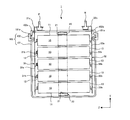
- FIG. 1 is a diagram illustrating an internal structure of a battery block (corresponding to a power storage device) according to the present embodiment.
- the battery block 1 includes a plurality of unit cells (corresponding to power storage elements) 10 and a case 100 that houses the plurality of unit cells 10.
- the case 100 has a case main body 101 and a lid 102.
- the lid 102 is fixed to the upper end portion of the case main body 101 and closes the opening 101 a formed in the case main body 101.
- the case main body 101 and the lid 102 can be formed of resin, for example.
- the plurality of single cells 10 accommodated in the case 100 are arranged as shown in FIG. 1 and 2, the X axis, the Y axis, and the Z axis are axes orthogonal to each other.
- the plurality of single cells 10 can be arranged in an arrangement different from the arrangement shown in FIG. Further, the number of the single cells 10 can be appropriately set in consideration of the required output of the battery block 1 and the like.
- a plurality of single cells 10 are held by a holder 20.
- the holder 20 holds the central portion of each unit cell 10 in the X direction.
- the holder 20 has as many openings 21 as the number of unit cells 10.
- the plurality of unit cells 10 are arranged side by side in the XY plane. In the example of FIG. 2, a row of five unit cells 10 arranged in the Y direction and a row of four unit cells 10 arranged in the Y direction are arranged side by side in the X direction.
- the holder 20 holds the central portion of the unit cell 10, but can also hold other portions (for example, the end of the unit cell 10).
- a plurality of unit cells 10 can be held using a plurality of holders 20.
- the unit cell 10 is inserted into the opening 21, and the gap formed between the opening 21 and the unit cell 10 is filled with an adhesive.
- an adhesive can be used as the adhesive.
- the unit cell 10 can be fixed to the holder 20 by filling the gap formed between the opening 21 and the unit cell 10 with an adhesive.
- an elastically deformable resin frame is provided in the gap formed between the opening 21 and the unit cell 10 instead of the epoxy resin so that the unit cell 10 is inserted and held in the holder 20 through the resin frame. It can also be configured.
- the holder 20 can be formed of a metal such as aluminum, for example.
- a metal such as aluminum, for example.
- the unit cell 10 may generate heat due to charging / discharging or the like. If the holder 20 is formed of metal, the heat generated in the unit cell 10 can be easily released to the holder 20, and the temperature increase of the unit cell 10 can be suppressed.
- the heat dissipation of the unit cell 10 can be similarly improved with the holder 20 formed of a resin material having high thermal conductivity other than the metal material.
- the holder 20 is fixed to the case 100.
- a structure for fixing the holder 20 to the case 100 a known structure can be appropriately used.
- the holder 20 can be fixed to the case 100 using a bolt.
- the single battery 10 is a so-called cylindrical battery. That is, the single cell 10 extends in the Z direction, and the cross-sectional shape of the single cell 10 in the XY plane is circular.
- a 18650 type battery can be used as the unit cell 10.
- the 18650 type battery is a cylindrical battery having a diameter of 18 [mm] and a length of 65.0 [mm], and is formed in a long shape.
- the single battery 10 can be a secondary battery such as a nickel metal hydride battery or a lithium ion battery, and an electric double layer capacitor (capacitor) can be used instead of the secondary battery.
- the cell 10 includes a battery case 11 and a power generation element housed in the battery case 11.
- the power generation element is an element that performs charge and discharge, and includes a positive electrode plate, a negative electrode plate, and a separator disposed between the positive electrode plate and the negative electrode plate.
- the separator contains an electrolytic solution.
- the positive electrode plate of the power generation element is electrically connected to the positive electrode terminal 12 provided at one end in the longitudinal direction of the unit cell 10 in the Z direction.
- the positive terminal 12 has a convex surface.
- the negative electrode plate of the power generation element is electrically connected to the negative electrode terminal 13 provided at the other longitudinal end of the unit cell 10 in the Z direction.
- the negative electrode terminal 13 is configured by a flat surface.
- the positive electrode terminal 12 and the negative electrode terminal 13 constitute a battery case 11.
- Each positive terminal 12 in the plurality of single cells 10 is located on the same side with respect to the holder 20 and is connected to a bus bar 31 as shown in FIGS. 1 and 2.
- the bus bar 31 is made of a conductive material such as metal.
- the bus bar 31 has connection portions 31b that come into contact with each positive electrode terminal 12 of the unit cell 10, and the connection units 31b are provided as many as the number of the unit cells 10 (positive electrode terminals 12).
- the connecting portion 31b can be formed by pressing (for example, punching or bending) the single plate member 31a.
- the connecting portion 31b is formed in a shape that protrudes from the plate-like member 31a toward the positive electrode terminal 12 of the unit cell 10.
- the connection part 31b and the positive electrode terminal 12 are welded.
- the bus bar 31 (plate-like member 31a) is arranged at a predetermined distance from the plurality of single cells 10 (positive electrode terminals 12) in the Z direction.
- a connection portion 31 b protruding in the Z direction from the plate-like member 31 a is connected to the positive electrode terminal 12 of the unit cell 10.
- the entire bus bar 31, which is a positive electrode bus bar, has a positive charge of each of the plurality of unit cells 10.
- the bus bar 31 has a lead portion 31 c, and the lead portion 31 c passes through an opening 102 a formed in the lid 102 of the battery block 1 and protrudes outside the case 100.
- the positive terminal P of the battery block 1 is fixed to the lead portion 31c.
- Each negative electrode terminal 13 in the plurality of unit cells 10 is located on the bottom side of the battery case 11 facing the positive electrode terminal 12 in the longitudinal direction with respect to the holder 20, and a bus bar 32 (corresponding to the connecting member of the present invention). Connected with.
- the bus bar 32 is made of a conductive material such as metal.
- the bus bar 32 which is a negative electrode bus bar, has a connection part 32 b that contacts the negative electrode terminal 13 of the unit cell 10.
- the connection part 32b is provided by the number of the single cells 10 (negative electrode terminal 13), and the connection part 32b and the negative electrode terminal 13 are welded.
- the connecting member 32 has a lead portion 32 c, and the lead portion 32 c passes through the opening 102 b formed in the lid 102 and protrudes to the outside of the case 100.
- the negative terminal N of the battery block 1 is fixed to the lead portion 32c.
- the plurality of unit cells 10 are arranged side by side so that the direction of the positive electrode terminal 12 (or the negative electrode terminal 13) of the unit cell 10 is the same direction, and one bus bar 31 for each of the positive electrode terminals 12.
- one bus bar 32 second connection member
- the battery block 1 (assembled battery) is configured by connecting all the unit cells 10 in parallel
- the present invention is not limited to this.
- the battery block 1 can also be configured by connecting a battery group of a plurality of unit cells 10 connected in parallel in series.
- the battery block 1 can be mounted on a vehicle and used as a power source for running the vehicle.
- a battery pack can be configured by electrically connecting a plurality of battery blocks 1 in series, and the battery pack can be mounted on a vehicle.
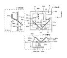
- FIG. 4 is a diagram showing an overall configuration of the bus bar 32 connected to the negative electrode terminal 13 of the unit cell 10.
- the bus bar 32 of the present embodiment is provided with a plurality of connection portions 32b corresponding to the plurality of single cells 10 formed integrally with the plate-like member 32a (corresponding to the substrate of the present invention).
- the battery 10 is disposed at a predetermined distance from the negative electrode terminal 13 of the unit cell 10 (see FIG. 1).
- connection part 32b formed in the bus bar 32 of the present embodiment is a connection part that is electrically connected to the negative electrode terminal 13 of the unit cell 10, and melts and melts when a current of a predetermined value or more flows. 10 (negative electrode terminal 13) is used as a fuse that cuts off electrical connection.
- the plate-like member 32a is a flat plate material having the Z direction as the thickness (plate thickness) direction. As shown in FIG. 4, a plurality of connecting portions 32b are formed by press punching at predetermined intervals at each position corresponding to the arrangement position of the unit cells 10 (negative electrode terminals 13) with the Z direction as the punching direction. Yes.
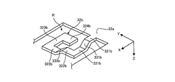
- FIG. 5 is a schematic perspective view showing the configuration of the connection portion 32b of the bus bar 32.
- FIG. 6 is a diagram illustrating a configuration example in which the connection portion 32b of the bus bar 32 is viewed from each direction in the XYZ (three-dimensional) direction.
- the connecting portion 32 b is configured to include a plurality of extending portions extending substantially parallel to a direction orthogonal to the punching direction (Z direction).
- the extending portion 321b extends in the X direction from the plate member 32a
- the extending portion 322b is bent from the extending portion 321b and extends in the Y direction.
- the extending portion 323b is bent from the extending portion 322b and extends in the X direction opposite to the extending direction of the extending portion 321b.
- Each extending portion 321b, 322b, 323b can be formed by punching the regions S1 to S4 of the plate-like member 32a in the Z direction.
- the extending portion 321b is a plate-like extending portion having a width D in the Y direction, and one end (base) is formed integrally with the plate-like member 32a.
- the extending portion 321b extending in the X direction is separated from the plate member 32a via the region S1 in the Y direction.
- the extended portion 322b is a plate-like extended portion having a width D in the X direction, and is bent about 90 degrees in the Y direction from the other end of the extended portion 321b.
- the extending portion 322b extending in the Y direction is separated from the plate-like member 32a via the region S2 in the X direction.
- the extending portion 323b is a plate-like extending portion having a width D in the Y direction, bent from the other end of the extending portion 322b by about 90 degrees in the X direction, and substantially parallel to the extending portion 321b in the X direction. It extends. That is, the extending portion 323b is an extending portion that extends in the X direction toward the base of the extending portion 321b (inward) in a direction opposite to the direction extending in the X direction of the extending portion 321b.
- the extending portion 323b is separated from the plate member 32a via the region S3 in the Y direction and is separated from the plate member 32a via the region S4 in the X direction.
- a contact portion 324b that contacts the negative electrode terminal 13 of the unit cell 10 and is connected to the negative electrode terminal 13 by welding is formed at the tip of the extended portion 323b.
- the contact portion 324b is formed in a convex shape from the extending portion 323b toward the inside in the Y direction.
- the contact portion 324b has an arbitrary shape depending on the positional relationship with the negative electrode terminal 13 of the unit cell 10. Can be.
- the tip of the extended portion 323b can be connected to the negative electrode terminal 13 of the unit cell 10 as it is as the contact portion 324b.
- the contact part 324b can also be formed wider in the X direction or the Y direction than each extending part.
- connection portion 32b of the present embodiment is formed by stamping the same or larger area as the negative electrode terminal 13 (bottom portion of the battery case 11) of the unit cell 10 by press punching.
- connection portion 32b a plurality of extending portions extending from the plate-like member 32a are spirally arranged toward the center where the central portion of the negative electrode terminal 13 is located in the punched region R.
- a plurality of extending portions are formed so as to be U-shaped as a whole, and in the region R where the connecting portion 32b of the plate-like member 32a is formed, the extending portion 321b is used as a base end.
- a punching process is performed so as to leave each extending portion, and a connection portion 32b formed integrally with the plate-like member 32a is provided in the punched region R.
- the extending part 323b of the present embodiment is formed so as to extend in the X direction from the extending part 322b in the direction opposite to the extending direction of the extending part 321b. For this reason, the size of the connection part 32b can be reduced (compact).
- connection portion 32b formed in a U-shape is illustrated, but other shapes may be used, for example, an extension portion 321b in which a bent portion described later is formed, It can also be set as the L-shaped connection part 32b comprised only by 322b.
- connection portion 32 b is formed so as to protrude in the Z direction (punching direction) from the plate-like member 32 a toward the negative electrode terminal 13, and in the extending portions 321 b and 322 b of the present embodiment, Bent portions 331b and 332b bent in the punching direction are formed.
- the bent portion 331b can be formed by bending the entire extending portion 321b extending in the X direction along the X direction orthogonal to the punching direction.
- the bent portion 331b has the same width D in the Y direction as the extended portion 321b, and forms a step in the Z direction with respect to the extended portion 322b.
- the bent portion 331b is bent in the extending portion 321b extending in the X direction so that the plate thickness surface is away from the bus bar 32 from the bending line P1 in the width direction, and the plate thickness surface is bent from the bend line P2 to the bus bar 32. It is formed by being bent so as to be substantially parallel to the XY plane so as to approach each other. This bending process can be performed simultaneously with the punching process or in a process different from the punching process.
- the bent portion 332b can be formed by bending the entire extending portion 322b extending in the Y direction along the Y direction orthogonal to the punching direction. As shown in FIG. 6, the bent portion 332b has the same width D in the X direction as the extended portion 322b, and forms a step in the Z direction with respect to the extended portion 323b. Similarly to the bent portion 331b, the bent portion 332b is bent in the extending portion 322b extending in the Y direction so that the plate thickness surface is away from the bus bar 32 from the bending line P3 in the width direction, and the plate thickness surface is bent from the bend line P4 to the bus bar 32. It is formed by being bent so as to be substantially parallel to the XY plane so as to be closer to.
- each of the bent portions 331b and 332b has the entire plate thickness surface based on bending lines (folded lines) P1 to P4 extending in the width direction in the respective regions of the plate-like extending portions 321b and 322b. It is formed by bending.
- the bent portion 331b is formed by bending the entire extending portion 321b in the thickness direction along the X direction perpendicular to the punching direction (XZ plan view in FIG. 6), and the bent portion 332b is formed by punching.
- the entire extending portion 322b is bent in the thickness direction along the Y direction orthogonal to the direction (YZ plan view of FIG. 6).
- the bent portion 331b and the bent portion 332b are bent in the punching direction and face each direction (X direction, Y direction) orthogonal to each other in the direction orthogonal to the punching direction.
- the bent portions 331b and 332b are bent in the same direction so as to protrude toward the side where the negative electrode terminal 13 of the unit cell 10 is located in the Z direction.
- the cell 10 negative electrode terminal 13
- the bus bar 32 connection portion 32 b
- the cell 10 negative electrode terminal 13
- the bus bar 32 connection portion 32 b
- the stress of the XYZ direction accompanying these displacements acts with respect to the connection part 32b.
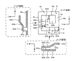
- FIG. 7 is a diagram illustrating an example of absorption / dispersion of stress applied to the connection portion 32b according to the longitudinal displacement of the unit cell 10 in the positional relationship between the bus bar 32 and the unit cell 10, that is, the Z direction displacement. .
- the entire connection portion 32b has the same thickness as the plate-like member 32a, and the plate thickness surface faces the Z direction. For this reason, with respect to the displacement between the unit cell 10 and the connection portion 32b in the Z direction, the entire connection portion 32b functions as a leaf spring that bends in the thickness direction, and stress is absorbed and dispersed in the thickness direction. . That is, the shearing force in the length direction of the plate material orthogonal to the plate thickness surface is suppressed, and the entire connection portion 32b absorbs and disperses the stress acting in the Z direction in the thickness direction.
- connection portion 32b connected to the negative electrode terminal 13 of the unit cell 10 is displaced in a direction away from the bus bar 32 (plate member 32a) (see the upper diagram of FIG. 7), the press fracture surface of the connection portion 32b. No stress is applied from the direction orthogonal to the direction, the shearing force in the width direction of each extending portion 321b, 322b, 323b is suppressed, and each extending portion 321b, 322b, 323b is bent so as to spread in the thickness direction, Stress is absorbed and dispersed.
- connection part 32b connected to the negative electrode terminal 13 of the cell 10 is displaced in a direction approaching the bus bar 32 (plate-like member 32a) (see the lower figure in FIG. 7)
- the extended parts 321b, 322b, and 323b Is bent so as to approach (narrow) in the thickness direction, and the stress is absorbed and dispersed.
- the extended portions 321b, 322b, and 323b function as leaf springs on the plate thickness surface in a state in which no stress acts from a direction orthogonal to the press fracture surface of the connection portion 32b.
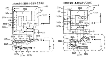
- FIG. 8 is a diagram illustrating an example of stress absorption / dispersion in the connection portion 32b in accordance with displacement in the X direction (first direction) orthogonal to the longitudinal direction of the unit cell 10.
- the unit cell 10 when the unit cell 10 is displaced in a direction away from the plate member 32a along the extending portion 321b extending in the X direction (in the X direction, the region S4 becomes wider and the region S2 becomes narrower).
- the bending portion 331b is displaced so that the inclined surface inclined in the Z direction is substantially parallel to the XY plane, while the entire extending portion 321b is close to the bus bar 32 in the Z direction.
- the displacement of the unit cell 10 in the X direction absorbs and disperses the stress applied to the extended portion 321b by extending in the X direction so that the angle of the inclined surface inclined in the Z direction of the bent portion 331b becomes loose.
- the stress is absorbed and dispersed by bending in the thickness direction (Z direction) so that the entire extending portion 321b approaches the bus bar 32.
- the unit cell 10 when the unit cell 10 is displaced in a direction approaching the plate-like member 32a along the extending portion 321b extending in the X direction (displacement in the X direction in which the region S2 becomes wider in the X direction and the region S4 becomes narrower).
- the bent portion 331b is displaced so that the inclined surface inclined in the Z direction approaches substantially perpendicular to the XY plane, and the extended portion 321b is displaced so as to approach the bus bar 32 in the Z direction.
- the stress due to the displacement of the unit cell 10 in the X direction is the stress applied to the extending portion 321b by contracting in the X direction so that the angle of the inclined surface inclined in the Z direction of the bent portion 331b becomes steep. While being absorbed and dispersed, the stress is absorbed and dispersed by bending in the thickness direction (Z direction) so that the entire extending portion 321b approaches the bus bar 32.
- the bending portion 331b changes its inclination in the Z direction with respect to the displacement in the X direction of the connecting portion 32b, and is displaced so as to extend or contract in the X direction. Then, the X-direction displacement of the bent portion 331b is converted as a deflection of the plate thickness surface in the Z direction of the extending portion 321b, and the entire extending portion 321b bends in the thickness direction, with respect to the X-direction displacement of the connecting portion 32b. Stress is absorbed and dispersed.
- extension part 321b when the extension part 321b is displaced in the Z direction so as to approach the bus bar 32 with respect to the displacement in the X direction, the extension part 322b can bend in the Z direction in its thickness direction, and the connection part 32b Stress can be absorbed and dispersed with respect to displacement in the X direction.
- FIG. 9 is a diagram illustrating an example of stress absorption / dispersion in the connection portion 32b in accordance with displacement in the Y direction (second direction) orthogonal to the longitudinal direction of the unit cell 10.
- the bent portion 332b is inclined in the Z direction. While the inclined surface is displaced so as to be substantially parallel to the XY plane, the entire extending portion 322b is displaced away from the bus bar 32 in the Z direction.
- the stress due to the displacement of the unit cell 10 in the Y direction is absorbed by the stress applied to the extending portion 322b by extending in the Y direction so that the angle of the inclined surface inclined in the Z direction of the bent portion 332b becomes loose.
- the stress is absorbed and dispersed by bending in the thickness direction (Z direction) so that the entire extending portion 322b moves away from the bus bar 32.
- the bent portion 332b has an inclined surface inclined in the Z direction on the XY plane.
- the entire extending portion 322b is displaced so as to approach the bus bar 32 in the Z direction while being displaced so as to be substantially perpendicular to the vertical direction.
- the stress due to the displacement of the unit cell 10 in the Y direction is the stress applied to the extending portion 322b by contracting in the Y direction so that the angle of the inclined surface inclined in the Z direction of the bent portion 332b becomes steep.
- the stress is absorbed and dispersed by bending in the thickness direction (Z direction) so that the entire extending portion 322b approaches the bus bar 32.
- the bending portion 332b changes its inclination in the Z direction with respect to the displacement of the connecting portion 32b in the Y direction, and is displaced so as to extend or contract in the Y direction. Then, the Y-direction displacement of the bent portion 332b is converted as the deflection of the plate thickness surface in the Z direction of the extending portion 322b, and the entire extending portion 322b bends in the thickness direction, with respect to the Y-direction displacement of the connecting portion 32b. Stress is absorbed and dispersed. Even in the displacement in the Y direction, the extended portion 321b can bend in the Z direction as a whole in the thickness direction, and stress can be absorbed and dispersed with respect to the displacement in the Y direction of the connecting portion 32b.
- the bent portion 331b is formed by bending the extending portion 321b in the thickness direction along the X direction orthogonal to the punching direction, and the bent portion 332b extends along the Y direction orthogonal to the punching direction.
- the extending portion 322b is bent in the thickness direction.
- the bent portion 331b and the bent portion 332b are inclined in the X direction and the Y direction orthogonal to each other in the direction orthogonal to the punching direction.
- each of the extending portions 321b and 322b bends like a leaf spring in the thickness direction with respect to displacement in the X and Y directions perpendicular to the punching direction, and stress in the X and Y directions applied to the connecting portion 32b is increased. It is absorbed and dispersed by the plate thickness surface of the connecting portion 32b. In addition, the stress can be absorbed and dispersed by the plate thickness surface of the connecting portion 32b even with respect to the displacement in the punching direction. Therefore, it can suppress that a shearing force acts on the press fracture surface of the connection part 32b, and can absorb and disperse the stress with respect to the displacement in the three-dimensional direction between the unit cell 10 and the bus bar 32 due to vibration or the like efficiently. .
- connection portion 32b of the present embodiment has a predetermined fusing characteristic as a fuse. Therefore, the width D in each direction of each of the extending portions 321b, 322b, and 323b constituting the connection portion 32b can be set to a size that blows when a current of a predetermined value or more set in advance as a fusing characteristic flows. .
- the connecting portion 32b functions as a fuse and is orthogonal to the punching direction by the bent portions 331b and 332b.
- a bus bar 32 that can absorb and disperse stress in each direction and can efficiently absorb and disperse the stress in the three-dimensional direction between the cell 10 and the bus bar 32 due to vibration or the like can be realized. .
- FIG. 10 is a schematic perspective view showing a modification of the connection portion 32b of the present embodiment.
- FIG. 11 is a diagram illustrating a configuration of the connection portion 32b in the modification example illustrated in FIG. 10, and is a diagram illustrating a configuration example of the connection portion viewed from each direction in the three-dimensional direction.
- connection portion 32b of this modification the bending directions of the two bent portions of the bent portions 331b and 332b are different from each other in the punching direction.
- the bent portion 331b has an extension portion 321b extending in the X direction from the bus bar 32 on the side opposite to the negative electrode terminal 13 side of the unit cell 10 in the Z direction from the bending line P1 in the width direction. Is formed by being bent in a direction approaching the case body 101 located on the outer side, and bent so that the plate thickness surface approaches the bus bar 32 from the bend line P2 so as to be substantially parallel to the XY plane.
- the bent portion 332b is bent in a direction closer to the negative electrode terminal 13 side of the unit cell 10 in the Z direction from the extending portion 321b located on the case body 101 side than the plate-like portion 32a, and is similar to the example of FIG. It is formed so as to be in the bending direction.
- each of the extending portions 321b and 322b bends like a plate spring on the plate thickness surface with respect to the displacement in the X direction and the Y direction orthogonal to the punching direction, and in the punching direction. Since the plate thickness surface of the connection portion 32b is bent like a leaf spring even with displacement, the entire connection portion 32b can absorb and disperse the stress on the plate thickness surface.
- the modification shown in FIG. 10 and the like can be applied, for example, in accordance with the space between the case main body 101 and the bus bar 32 in the Z direction (see FIG. 1). Compared to the example of FIG. And the negative electrode terminal 13 of the unit cell 10 can be narrowed.
- the extending portions 321b and 322b are formed along the X direction and the Y direction, respectively.
- the bent portions 331b and 332b are formed in the respective directions inclined from the X direction and the Y direction.
- the extending portions 321b and 322b may be provided so as to face in directions orthogonal to each other. That is, each of the bent portions 331b and 332b only needs to face each other in each direction orthogonal to the punching direction, and may not be provided along each of the X direction and the Y direction.
- a connecting portion 32b in which bent portions in the same or different bending directions are formed in the extended portion 323b and bent portions are formed in the extended portions 321b, 322b, and 323b, respectively.
- at least two of the three bent portions can be provided so as to face each other in a direction orthogonal to the punching direction.
- at least two bent portions may be provided in the extended portion 321b and the extended portion 323b, or in the extended portion 322b and the extended portion 323b, respectively.
- the extending portions 321b, 322b, and 323b are integrally formed in a substantially U shape, and the bent portion is approximately 90 degrees, but the present invention is not limited to this.
- the extending portions 321b, 322b, and 323b are bent at an arbitrary angle so that the bent portions 331b and 332b face each other in each direction orthogonal to the punching direction to form the connection portion 32b.
- the bent portion can be, for example, a rounded curved shape.
- connection part 32b of a present Example can be applied to both or one of a positive electrode bus bar and a negative electrode bus bar.
- Example 2 12 to 14 are diagrams showing Embodiment 2 of the present invention.
- members having the same functions as those described in the first embodiment are denoted by the same reference numerals, and detailed description thereof is omitted.
- differences from the first embodiment will be mainly described.
- FIG. 12 is a schematic perspective view showing the configuration of the connecting portion 320b of the bus bar 32 of the present embodiment.
- FIG. 13 is a diagram illustrating a configuration of the connection portion 320b of the bus bar 32, and is a diagram illustrating a configuration example of the connection portion viewed from each direction in the three-dimensional direction.
- the connecting portion 320b of the bus bar 32 of this embodiment includes an extending portion 341b extending in the Y direction, an extending portion 342b extending in the X direction from the extending portion 341b, and an extending portion 342b extending in the X direction. And an extension portion 343b extending in the Y direction opposite to the direction in which the extension portion 341b extends, and bent in the X direction from the extension portion 343b and in the direction opposite to the extension direction of the extension portion 342b And an extending portion 344b extending in the direction.
- the extending portions 341b, 342b, 343b, and 344b are integrally formed from the plate-like member 32a with the extending portion 341b as a base end.
- the extending portion 341b extends from the plate member 32a, and extends in the Y direction so that the plate thickness surface is substantially parallel to the direction orthogonal to the punching direction via the plate member 32a and the region S1a.
- the extending portions 342b and 343b are also provided so as to be substantially parallel to the direction orthogonal to the punching direction via the regions S1 and S2.
- the contact part 345b which contacts the negative electrode terminal 13 of the cell 10 and is connected to the negative electrode terminal 13 by welding is formed at the tip of the extended part 344b, as in the first embodiment.
- the bending part 351b of a present Example is formed by bending the bending part 361b between the extension part 341b and the extension part 342b from the surface orthogonal to the punching direction substantially parallel to the punching direction.
- the plate thickness surface of the bent portion 361b is substantially parallel to the punching direction along the bent lines P5 and P6 extending in the first direction inclined from the X direction to the Y direction at the bent portion 361b. It is formed by being bent like this.
- the bend line P5 and the bend line P6 are bend lines provided in the extended portion 341b and the extended portion 342b, respectively, and the bend line P5 is inclined in the X direction with respect to the width direction of the extended portion 341b extending in the Y direction.
- the bending line P6 extends in an inclined direction in the Y direction with respect to the width direction of the extending portion 341b extending in the X direction.
- these bending lines P5 and P6 are connected in a straight line to form a bending line extending in the first direction.
- the bent portion 351b is formed by bending the bending member 361b so that the plate thickness surface thereof is substantially parallel to the punching direction so that at least a part of the corner 361c of the bent portion 361b is included.
- the plate thickness surface is not arranged substantially parallel to the direction orthogonal to the punching direction.
- the bent portion 352b of this embodiment is formed by bending a bent portion 362b between the extended portion 342b and the extended portion 343b from a surface orthogonal to the punching direction so as to be substantially parallel to the punching direction.
- the bent portion 352b is bent along the bending lines P7 and P8 extending in the second direction inclined in the X direction from the Y direction at the bent portion 362b so that the plate thickness surface of the bent portion 362b is substantially parallel to the punching direction.
- the second direction is a direction orthogonal to the first direction of the bent portion 361b in the direction orthogonal to the punching direction.
- the bend line P7 and the bend line P8 are bend lines provided in the extended portion 342b and the extended portion 343b, respectively, and the bend line P7 is inclined in the Y direction with respect to the width direction of the extended portion 342b extending in the X direction.
- the bend line P8 extends inclining in the X direction with respect to the width direction of the extending portion 343b extending in the Y direction.
- these bending lines P7 and P8 are connected in a straight line to form a bending line extending in the second direction.
- the plate thickness surface of the bending member 362b is bent substantially parallel to the punching direction so that at least a part of the corner portion 362c of the bent portion 362b is included.
- the plate thickness surface is not arranged substantially parallel to the direction orthogonal to the punching direction.
- the plate thickness surface is substantially parallel to the punching direction (Z direction), and each plate thickness surface is in the first direction and the first direction in the XY plan view orthogonal to the Z direction.
- the two directions are orthogonal to each other.
- the extended portion 343b has a bent portion formed by bending the entire plate thickness surface in the Z direction with bending lines P9 and P10 extending in the width direction as the base, similar to the bent portion shown in the first embodiment. 353b is provided.
- the extending portions 343b and 344b are formed so as to protrude toward the negative electrode terminal 13 side of the unit cell 10 by the bent portion 353b.
- FIG. 14 is a diagram illustrating an example of stress absorption / dispersion in the connection portion 320b according to displacement in the X direction and the Y direction orthogonal to the longitudinal direction of the unit cell 10 of the present embodiment.
- the bent portion 351b has a plate thickness surface bent substantially parallel to the punching direction, so that the plate thickness surface can be bent in the XY plane, and the connection portion 320b is displaced with respect to the displacement in the XY direction. It can absorb and disperse stress.
- the bent portion 352b can bend in the XY plane, and can absorb and disperse stress due to displacement of the connecting portion 320b in the XY direction.
- the bent portions 351b and 352b of the present embodiment are such that the plate thickness surfaces of the bent portions 361b and 362b bent substantially parallel to the punching direction are respectively bent in the direction perpendicular to the punching direction, the X direction due to vibration, and the like.
- the stress with respect to the displacement in the Y direction can be absorbed and dispersed.
- the bent portions 361 b and 362 b are arranged at different positions in the X direction, and with respect to the displacement of the contact portion 345 b connected to the negative electrode terminal 13, There are two axes on which the plate thickness surface for absorbing and dispersing stress bends. For this reason, the rotational trajectory of the XY plane around the bent portions 361b and 362b is allowed with two axes. For example, when the stress is absorbed / dispersed only by the bent portion 351b, only one rotation trajectory centered on the bent portion 361b can be allowed, but the other rotation trajectory centered on the bent portion 362b is allowed by the bent portion 352b. Allowed, the stress can be efficiently absorbed and dispersed by the deflection of the plate thickness surface with respect to the entire displacement of the XY plane.
- the displacement in the punching direction can also be absorbed and dispersed by the plate thickness surfaces facing each other in the Z direction of the extending portions 341b, 342b, 343b, 344b.
- the stress with respect to the displacement in the three-dimensional direction between the unit cell 10 and the bus bar 32 can be efficiently absorbed and dispersed.
- the extending portion 343b is formed so as to extend in the Y direction opposite to the extending direction of the extending portion 341b, and the extending portion 344 extends in the direction in which the extending portion 342b extends. Is formed to extend in the X direction in the opposite direction, the size of the connection portion 320b can be reduced (compact).
- connection portion 320b of the present embodiment the bending directions of the two bent portions 351b and 352b are different from each other in a direction substantially parallel to the punching direction. Orientation may be used.
- Battery block (power storage device) 10 Single battery (power storage element) 11: Battery case 12: Positive terminal 13: Negative terminal 20: Holder 31, 32: Bus bar (connection member) 31b, 32b: Connection portions 321b, 322b, 323b, 341b, 342b, 343b, 344b : Extension part 331b, 332b, 351b, 352b, 353b: Bending part
Landscapes
- Engineering & Computer Science (AREA)
- Power Engineering (AREA)
- Microelectronics & Electronic Packaging (AREA)
- Chemical & Material Sciences (AREA)
- Chemical Kinetics & Catalysis (AREA)
- Electrochemistry (AREA)
- General Chemical & Material Sciences (AREA)
- Combustion & Propulsion (AREA)
- Physics & Mathematics (AREA)
- Thermal Sciences (AREA)
- Connection Of Batteries Or Terminals (AREA)
- Electric Double-Layer Capacitors Or The Like (AREA)
- Fuses (AREA)
Abstract
ヒューズとしての溶断特性を備えつつ、振動等による蓄電素子と接続部材との間の3次元方向の変位に対して効率良く応力を吸収・分散させることができる接続部材を提供する。接続部材は、複数の蓄電素子で構成される蓄電装置の各蓄電素子を電気的に接続する接続部材である。接続部材は、基板と、各蓄電素子の電極と接続されるとともに、所定値以上の電流が流れた際に溶断して蓄電素子との電気的な接続を遮断する複数の接続部と、を備える。接続部は、基板が打ち抜き加工されることにより形成されるとともに、打ち抜き方向に折り曲げられた少なくとも2つの折曲部を有する。そして、一方の折曲部が打ち抜き方向に直交する第1方向に沿って折り曲げられ、他方の折曲部が打ち抜き方向に直交しかつ第1方向に直交する第2方向に沿って折り曲げられている。
Description
本発明は、複数の蓄電素子が電気的に接続された蓄電装置に関する。より詳細には、各蓄電素子の正極又は負極に接続されるバスバー(接続部材)に関する。
特許文献1は、複数の円筒型電池の各正極を接続する正極バスバーと、各負極を接続する負極バスバーとが設けられている。円筒型電池の正負極は、各バスバーに対してヒューズ(電流遮断器)で接続されている。ヒューズとしてリード線を用いており、過電流等の所定値以上の電流が流れると、発熱等により溶断してバスバーと円筒型電池の正負極との電気的接続が遮断される。
特許文献1では、電池及びバスバーに対して別体のヒューズを用いており、バスバーとヒューズ及び円筒型電池とヒューズをそれぞれ接続しなければならない。ヒューズがバスバーと別体であることから、バスバーと円筒型電池との組付公差や振動変位などを許容した接点を確保し難い課題がある。
このため、組付公差や振動等の変位による応力を考慮した対策をヒューズに施す必要がある。しかしながら、ヒューズを細くすると振動等の変位を吸収し易くなるものの、流れる電流量が小さくなるので、発熱量の増加とともに、流れる許容電流量が抑制されてしまう。一方、ヒューズを太くして流れる電流量を大きくすると、発熱の増加や許容電流量の抑制を緩和できるものの、逆に振動等の変位を吸収し難くなる。
そこで、本発明の目的は、複数の蓄電素子で構成される蓄電装置の各蓄電素子を電気的に接続する接続部材において、ヒューズとしての溶断特性を備えつつ、振動等による蓄電素子と接続部材との間の3次元方向の変位に対して効率良く応力を吸収・分散させることができる接続部材を提供することにある。
本願第1の発明である接続部材は、複数の蓄電素子で構成される蓄電装置の各蓄電素子を電気的に接続する接続部材である。接続部材は、基板と、各蓄電素子の電極と接続されるとともに、所定値以上の電流が流れた際に溶断して蓄電素子との電気的な接続を遮断する複数の接続部と、を備える。接続部は、基板が打ち抜き加工されることにより形成されるとともに、打ち抜き方向に折り曲げられた少なくとも2つの折曲部を有する。そして、一方の折曲部が打ち抜き方向に直交する第1方向に沿って折り曲げられ、他方の折曲部が打ち抜き方向に直交しかつ第1方向に直交する第2方向に沿って折り曲げられている。
本願第1の発明によれば、基板と一体に形成される接続部が、打ち抜き方向に折り曲げられた少なくとも2つの折曲部を有している。そして、これら少なくとも2つの折曲部が、打ち抜き方向に直交しかつ互いに直交する第1方向及び第2方向それぞれに沿って折り曲げられている。このため、打ち抜き方向に直交する各方向において作用する応力が厚み方向に折り曲げられた各折曲部の曲げ変位で吸収・分散されつつ、打ち抜き方向に作用する応力が、接続部材全体の厚み方向の変位により吸収・分散される。
したがって、電流遮断器(ヒューズ)としての溶断特性を備えつつ、振動等による蓄電素子と接続部材との間の3次元方向の変位に対して効率良く応力を吸収・分散させることができる。
接続部は、第1方向に延びる第1延設部と、第1延設部から第2方向に延びる第2延設部と、を有するように構成することができる。そして、少なくとも2つの各折曲部は、第1延設部及び第2延設部それぞれを延設される方向に沿って打ち抜き方向に折り曲げることで形成することができる。また、当該接続部は、第2延設部から第1延設部の延びる方向とは逆向きの第1方向に延びる第3延設部をさらに有するように構成することができる。
接続部は、打ち抜き方向と直交する方向に略平行に延びる第1延設部と、第1延設部から屈曲し、打ち抜き方向と直交する方向に略平行に延びる第2延設部と、第2延設部から屈曲し、打ち抜き方向と直交する方向に略平行に延びる第3延設部と、を有することができる。このとき、一方の折曲部は、第1延設部及び第2延設部との間の屈曲した部位を、打ち抜き方向と直交する面から第1方向に沿って打ち抜き方向と略平行に折り曲げることで形成することができる。また、他方の折曲部は、第2延設部及び第3延設部との間の屈曲した部位を、打ち抜き方向と直交する面から第2方向に沿って打ち抜き方向と略平行に折り曲げることで形成することができる。さらに、第3延設部は、第2延設部から第1延設部の延びる方向とは逆向きの方向に延びるように形成することができる。
少なくとも2つの各折曲部の折れ曲がる方向は、打ち抜き方向おいて同じ向き、または互いに異なる向きとなるように構成することができる。
蓄電素子は、長手方向を有する円筒型の蓄電素子として構成できる。複数の蓄電素子は、長手方向端部に配置される正極又は負極が同じ向きとなるように並んで配置されている。接続部材は、複数の蓄電素子の各負極と接続されるように構成することができる。
上記接続部材によって電気的に並列に接続される複数の蓄電素子を有する蓄電装置が構成できる。
以下、本発明の実施例について説明する。
(実施例1)
図1から図11は、本発明の実施例1を示す図である。図1は、本実施例である電池ブロック(蓄電装置に相当する)の内部構造を示す図である。
図1から図11は、本発明の実施例1を示す図である。図1は、本実施例である電池ブロック(蓄電装置に相当する)の内部構造を示す図である。
電池ブロック1は、複数の単電池(蓄電素子に相当する)10と、複数の単電池10を収容するケース100とを有する。ケース100は、ケース本体101および蓋102を有する。蓋102は、ケース本体101の上端部に固定されており、ケース本体101に形成された開口部101aを塞いでいる。ケース本体101および蓋102は、例えば、樹脂で形成することができる。
ケース100に収容された複数の単電池10は、図2に示すように配置されている。図1および図2において、X軸、Y軸およびZ軸は、互いに直交する軸である。なお、複数の単電池10は、図2に示す配列とは異なる配列で配置することができる。また、単電池10の数は、電池ブロック1の要求出力などを考慮して適宜設定することができる。
複数の単電池10は、ホルダ20によって保持されている。図1に示すように、ホルダ20は、X方向における各単電池10の中央部分を保持している。ホルダ20は、図3に示すように、単電池10の数だけ、開口部21を有する。複数の単電池10は、X-Y平面内において、並んで配置されている。図2の例では、Y方向に並ぶ5つの単電池10の列と、Y方向に並ぶ4つの単電池10の列とが、X方向において並んで配置されている。
なお、本実施例において、ホルダ20は、単電池10の中央部分を保持しているが、他の部分(例えば、単電池10の端部)を保持することもできる。また、複数のホルダ20を用いて、複数の単電池10を保持することもできる。
開口部21には、単電池10が挿入され、開口部21および単電池10の間に形成された隙間には、接着剤が充填される。接着剤としては、例えば、エポキシ樹脂を用いることができる。開口部21および単電池10の間に形成された隙間に接着剤を充填することにより、ホルダ20に対して単電池10を固定することができる。また、エポキシ樹脂の代わりに、開口部21および単電池10の間に形成された隙間に弾性変形可能な樹脂枠を設け、樹脂枠を介してホルダ20に単電池10が挿入、保持されるように構成することもできる。
ホルダ20は、例えば、アルミニウムといった金属で形成することができる。ホルダ20を金属で形成することにより、単電池10の放熱性を向上させることができる。単電池10は、充放電などによって発熱することがある。ホルダ20を金属で形成しておけば、単電池10で発生した熱を、ホルダ20に逃がしやすくすることができ、単電池10の温度上昇を抑制することができる。なお、金属材料以外にも熱伝導性の高い樹脂材等で形成されたホルダ20でも同様に、単電池10の放熱性を向上させることができる。
ホルダ20は、ケース100に固定されている。ホルダ20をケース100に固定する構造は、公知の構造を適宜用いることができる。例えば、ボルトを用いて、ホルダ20をケース100に固定することができる。
単電池10は、いわゆる円筒型の電池である。すなわち、単電池10は、Z方向に延びており、X-Y平面における単電池10の断面形状は、円形に形成されている。単電池10としては、例えば、18650型の電池を用いることができる。18650型の電池は、直径が18[mm]、長さが65.0[mm]の円筒型の電池であり、長尺状に形成されている。また、単電池10は、ニッケル水素電池やリチウムイオン電池といった二次電池を用いることができ、二次電池の代わりに、電気二重層キャパシタ(コンデンサ)を用いることができる。
単電池10は、電池ケース11と、電池ケース11に収容された発電要素とを有する。発電要素は、充放電を行う要素であり、正極板と、負極板と、正極板および負極板の間に配置されたセパレータとを有する。セパレータは、電解液を含んでいる。
発電要素の正極板は、Z方向における単電池10の長手方向一端に設けられた正極端子12と電気的に接続されている。正極端子12は、凸面で構成されている。発電要素の負極板は、Z方向における単電池10の長手方向他端に設けられた負極端子13と電気的に接続されている。負極端子13は、平坦な面で構成されている。正極端子12および負極端子13は、電池ケース11を構成する。
複数の単電池10における各正極端子12は、ホルダ20に対して同一の側に位置しており、図1及び図2に示すように、バスバー31と接続されている。バスバー31は、金属といった、導電性を有する材料で形成されている。バスバー31は、単電池10の各正極端子12と接触する接続部31bを有しており、接続部31bは、単電池10(正極端子12)の数だけ設けられている。
接続部31bは、一枚の板状部材31aをプレス加工(打ち抜き加工や曲げ加工等)することにより形成することができる。接続部31bは、板状部材31aから単電池10の正極端子12に向かって突出した形状に形成されている。接続部31bおよび正極端子12は、溶接されている。
バスバー31(板状部材31a)は、Z方向において複数の単電池10(正極端子12)に対して所定距離離間して配置されている。板状部材31aからZ方向に突出した接続部31bが、単電池10の正極端子12に接続される。正極バスバーであるバスバー31全体は、複数の各単電池10の正極の電荷を帯びている。
バスバー31は、リード部31cを有しており、リード部31cは、電池ブロック1の蓋102に形成された開口部102aを通過して、ケース100の外部に突出している。リード部31cには、電池ブロック1の正極端子Pが固定されている。
複数の単電池10における各負極端子13は、ホルダ20に対して正極端子12と長手方向において対向する電池ケース11の底部側に位置しており、バスバー32(本発明の接続部材に相当する)と接続されている。バスバー32は、金属などの導電性を有する材料で形成されている。負極バスバーであるバスバー32は、単電池10の負極端子13と接触する接続部32bを有する。接続部32bは、単電池10(負極端子13)の数だけ設けられており、接続部32b及び負極端子13は、溶接されている。
また、接続部材32は、リード部32cを有しており、リード部32cは、蓋102に形成された開口部102bを通過して、ケース100の外部に突出している。リード部32cには、電池ブロック1の負極端子Nが固定されている。
本実施例の複数の単電池10は、単電池10の正極端子12(又は負極端子13)の向きが、同じ向きとなるように並んで配置され、正極端子12それぞれに対して1つのバスバー31(第1接続部材)が接続され、単電池10の負極端子13それぞれに対して1つのバスバー32(第2接続部材)を接続することにより、複数の単電池10が電気的に並列に接続されている。
なお、すべての単電池10が並列に接続されることによって、電池ブロック1(組電池)が構成される一例を挙げて説明しているが、これに限るものではない。例えば、電池ブロック1は、並列に接続された複数の単電池10の電池群を直列に接続して構成することもできる。
また、電池ブロック1は、車両に搭載し、車両を走行させるための動力源として用いることができる。具体的には、複数の電池ブロック1を電気的に直列に接続することによって、電池パックを構成し、電池パックを車両に搭載することができる。
次に、バスバー32(第2接続部材)について詳細に説明する。図4は、単電池10の負極端子13に接続されるバスバー32の全体構成を示す図である。本実施例のバスバー32は、バスバー31と同様に、板状部材32a(本発明の基板に相当する)と一体に形成される複数の各単電池10に対応した複数の接続部32bが設けられ、単電池10の負極端子13に対して所定間隔離間して配置される(図1参照)。
本実施例のバスバー32に形成される接続部32bは、単電池10の負極端子13と電気的に接続される接続部であるとともに、所定値以上の電流が流れた際に溶断して単電池10(負極端子13)との電気的な接続を遮断するヒューズとして用いられる。
板状部材32aは、Z方向を厚み(板厚)方向とした平面状の板材である。図4に示すように、Z方向を打ち抜き方向として、単電池10(負極端子13)の配列位置に対応する各位置に、複数の接続部32bが所定間隔を空けてプレス打ち抜き加工によって形成されている。
図5は、バスバー32の接続部32bの構成を示す概略斜視図である。図6は、バスバー32の接続部32bを、XYZ(3次元)方向の各方向から見た構成例を示す図である。
図5及び図6に示すように、接続部32bは、打ち抜き方向(Z方向)と直交する方向に略平行に延びる複数の延設部を含んで構成されている。打ち抜き方向(Z方向)に直交する方向において、延設部321bは、板状部材32aからX方向に延びており、延設部322bは、延設部321bから屈曲してY方向に延びている。また、延設部323bは、延設部322bから屈曲して延設部321bの延びる方向とは逆向きのX方向に延びている。各延設部321b,322b,323bは、板状部材32aの領域S1~S4をZ方向に打ち抜くことにより形成することができる。
延設部321bは、Y方向に幅Dを有する板状の延設部であり、一端(根元)が板状部材32aと一体的に形成されている。X方向に延びる延設部321bは、Y方向において領域S1を介して板状部材32aと離間している。
延設部322bは、X方向に幅Dを有する板状の延設部であり、延設部321bの他端からY方向に約90度屈曲している。Y方向に延びる延設部322bは、X方向において領域S2を介して板状部材32aと離間している。
延設部323bは、Y方向に幅Dを有する板状の延設部であり、延設部322bの他端からX方向に約90度屈曲し、延設部321bと略平行にX方向に延びている。つまり、延設部323bは、延設部321bのX方向に延びる方向とは逆の向きで、延設部321bの根元に向かって(内側に向かって)X方向に延びる延設部である。延設部323bは、Y方向において領域S3を介して板状部材32aと離間し、かつX方向において領域S4を介して板状部材32aと離間している。
延設部323bの先端には、単電池10の負極端子13と接触し、負極端子13に対して溶接により接続される接触部324bが形成されている。本実施例では、接触部324bを延設部323bからY方向内側に向かって凸状に形成した一例を示しているが、単電池10の負極端子13との位置関係に応じて適宜任意の形状にすることができる。また、延設部323bの先端をそのまま接触部324bとして、単電池10の負極端子13に接続することができる。なお、接触部324bは、各延設部よりもX方向又はY方向に幅広に形成することもできる。
このように本実施例の接続部32bは、単電池10の負極端子13(電池ケース11の底部)と同じまたは大きい領域がプレス打ち抜き加工で打ち抜かれて形成される。そして、接続部32bは、板状部材32aから延設される複数の延設部が、打ち抜かれた領域Rにおいて負極端子13の中央部位が位置する中心に向かって渦巻き状に配置されている。
本実施例では、全体がコの字状となるように複数の延設部が形成されており、板状部材32aの接続部32bが形成される領域Rにおいて、延設部321bを基端として各延設部を残すように打ち抜き加工し、打ち抜かれた領域R内で板状部材32aと一体に形成された接続部32bが設けられている。
なお、本実施例の延設部323bは、延設部321bの延びる方向とは逆向きで、延設部322bからX方向に延びるように形成されている。このため、接続部32bのサイズを小型化(コンパクト化)することができる。
また、本実施例では、コの字状に形成された接続部32bを例示しているが、他の形状であってもよく、例えば、後述する折曲部が形成される延設部321b,322bだけで構成されたL字状の接続部32bとすることもできる。
図6に示すように、接続部32bは、板状部材32aから負極端子13に向かってZ方向(打ち抜き方向)に突出するように形成され、本実施例の延設部321b,322bには、打ち抜き方向に折り曲げられた折曲部331b,332bが形成されている。折曲部331bは、X方向に延びる延設部321b全体を、打ち抜き方向に直交するX方向に沿って折り曲げることで形成することができる。折曲部331bは、延設部321bとY方向において同じ幅Dを有し、延設部322bに対してZ方向に段差を形成している。
具体的には、折曲部331bは、X方向に延びる延設部321bにおいて幅方向の曲げ線P1から板厚面がバスバー32から遠ざかる方向に折り曲げ、曲げ線P2から板厚面がバスバー32に近づくようにXY平面と略平行となるように折り曲げることで形成される。この曲げ加工は、打ち抜き加工と同時に又は打ち抜き加工とは別の工程で行うことができる。
折曲部332bは、Y方向に延びる延設部322b全体を、打ち抜き方向に直交するY方向に沿って折り曲げることで形成することができる。図6に示すように、折曲部332bは、延設部322bとX方向において同じ幅Dを有し、延設部323bに対してZ方向に段差を形成している。折曲部332bも折曲部331b同様に、Y方向に延びる延設部322bにおいて幅方向の曲げ線P3から板厚面がバスバー32から遠ざかる方向に折り曲げ、曲げ線P4から板厚面がバスバー32に近づくようにXY平面と略平行となるように折り曲げることで形成される。
ここで、折曲部331b,332bの関係について説明する。図6に示すように、各折曲部331b,332bは、板状の延設部321b,322bの各領域において幅方向に延びる曲げ線(折れ線)P1~P4を基点に、板厚面全体を折り曲げることで形成されている。
つまり、折曲部331bは、打ち抜き方向に直交するX方向に沿って延設部321b全体を厚み方向に折り曲げることで形成され(図6のX-Z平面視)、折曲部332bは、打ち抜き方向に直交するY方向に沿って延設部322b全体を厚み方向に折り曲げることで形成される(図6のY-Z平面視)。
このため、折曲部331b及び折曲部332bは、打ち抜き方向に折り曲げられているとともに、打ち抜き方向に直交する方向において互いに直交する各方向(X方向,Y方向)を向いている。ここで、折曲部331b,332bは、Z方向において、単電池10の負極端子13が位置する側に突出するように同じ向きに折り曲げられている。
電池ブロック1において、単電池10(負極端子13)とバスバー32(接続部32b)とは、電流が流れることによって接続部32が熱膨張・熱収縮して単電池10の負極端子13に対して変位したり、振動等により変位する。このため、接続部32bに対してこれらの変位に伴うXYZ方向の応力が作用する。
図7は、バスバー32と単電池10との間の位置関係において単電池10の長手方向変位、すなわち、Z方向変位に応じた接続部32bに加わる応力の吸収・分散の一例を示す図である。
図7に示すように、接続部32b全体は、板状部材32aと同じ厚みを有するとともに、板厚面がZ方向に面している。このため、Z方向における単電池10と接続部32bとの間の変位に対して、接続部32b全体が、厚み方向にたわむ板バネとして機能し、厚み方向での応力の吸収・分散が行われる。すなわち、板厚面に直交する板材の長さ方向に対するせん断力が抑制され、厚み方向において接続部32b全体が、Z方向に作用する応力を吸収・分散させている。
したがって、単電池10の負極端子13に接続された接続部32bが、バスバー32(板状部材32a)から遠ざかる方向に変位しても(図7の上図参照)、接続部32bのプレス破断面に直交する方向から応力が作用せず、各延設部321b,322b,323bの幅方向へのせん断力が抑制され、各延設部321b,322b,323bが厚み方向に広がるようにたわんで、応力が吸収・分散される。
また、単電池10の負極端子13に接続された接続部32bが、バスバー32(板状部材32a)に近づく方向に変位した場合(図7の下図参照)、各延設部321b,322b,323bが厚み方向に近づく(狭まる)ようにたわんで、応力が吸収・分散される。このときも、接続部32bのプレス破断面に直交する方向から応力が作用しない状態で、各延設部321b,322b,323bが板厚面での板バネとして機能する。
図8は、単電池10の長手方向に直交するX方向(第1方向)の変位に応じた接続部32bの応力の吸収・分散の一例を示す図である。
図8に示すように、例えば、単電池10がX方向に延びる延設部321bに沿って、板状部材32aから離れる方向に変位した場合(X方向において領域S4が広くなり、領域S2が狭くなるX方向の変位)、折曲部331bは、Z方向に傾斜した傾斜面がXY平面と略平行となるように変位しつつ、延設部321b全体がZ方向においてバスバー32に近づくように変位する。このとき、単電池10のX方向への変位は、折曲部331bのZ方向に傾斜した傾斜面の角度が緩くなるようにX方向に延びることで延設部321bに加わる応力が吸収・分散されるとともに、延設部321b全体がバスバー32に近づくように厚み方向(Z方向)にたわむことで、応力が吸収・分散される。
一方、例えば、単電池10がX方向に延びる延設部321bに沿って、板状部材32aに近づく方向に変位した場合(X方向において領域S2が広くなり、領域S4が狭くなるX方向の変位)、折曲部331bは、Z方向に傾斜した傾斜面がXY平面に対して略垂直に近づくように変位しつつ、延設部321b全体がZ方向においてバスバー32に近づくように変位する。このとき、単電池10のX方向への変位による応力は、折曲部331bのZ方向に傾斜した傾斜面の角度が急になるようにX方向に縮むことで延設部321bに加わる応力が吸収・分散されるとともに、延設部321b全体がバスバー32に近づくように厚み方向(Z方向)にたわむことで、応力が吸収・分散される。
このように、折曲部331bは、接続部32bのX方向変位に対してZ方向への傾斜が変化し、X方向において延びるように又は縮まるように変位する。そして、折曲部331bのX方向変位が延設部321bのZ方向における板厚面のたわみとして変換されて、延設部321b全体が厚み方向にたわみ、接続部32bのX方向変位に対して応力が吸収・分散がされる。なお、X方向変位に対して延設部321bがバスバー32に近づくようにZ方向に変位する際、延設部322bは、その厚み方向において全体がZ方向にたわむことができ、接続部32bのX方向変位に対して応力を吸収・分散することができる。
図9は、単電池10の長手方向に直交するY方向(第2方向)の変位に応じた接続部32bの応力の吸収・分散の一例を示す図である。
図9に示すように、例えば、単電池10がY方向に延びる延設部322bに沿って、Y方向において領域S3が狭くなるように変位した場合、折曲部332bは、Z方向に傾斜した傾斜面がXY平面と略平行となるように変位しつつ、延設部322b全体がZ方向においてバスバー32から遠ざかるくように変位する。このとき、単電池10のY方向への変位による応力は、折曲部332bのZ方向に傾斜した傾斜面の角度が緩くなるようにY方向に延びることで延設部322bに加わる応力が吸収・分散されるとともに、延設部322b全体がバスバー32から遠ざかるように厚み方向(Z方向)にたわむことで、応力が吸収・分散される。
一方、例えば、単電池10がY方向に延びる延設部322bに沿って、Y方向において領域S3が広くなるように変位した場合、折曲部332bは、Z方向に傾斜した傾斜面がXY平面に対して略垂直に近づくように変位しつつ、延設部322b全体がZ方向においてバスバー32に近づくように変位する。このとき、単電池10のY方向への変位による応力は、折曲部332bのZ方向に傾斜した傾斜面の角度が急になるようにY方向に縮むことで延設部322bに加わる応力が吸収・分散されるとともに、延設部322b全体がバスバー32に近づくように厚み方向(Z方向)にたわむことで、応力が吸収・分散される。
このように、折曲部332bは、接続部32bのY方向変位に対してZ方向への傾斜が変化し、Y方向において延びるように又は縮まるように変位する。そして、折曲部332bのY方向変位が延設部322bのZ方向における板厚面のたわみとして変換されて、延設部322b全体が厚み方向にたわみ、接続部32bのY方向変位に対して応力が吸収・分散がされる。なお、Y方向変位においても、延設部321bがその厚み方向において全体がZ方向にたわむことができ、接続部32bのY方向変位に対して応力を吸収・分散することができる。
本実施例では、折曲部331bが、打ち抜き方向に直交するX方向に沿って延設部321bを厚み方向に折り曲げることで形成され、折曲部332bが、打ち抜き方向に直交するY方向に沿って延設部322bを厚み方向に折り曲げることで形成されている。折曲部331b及び折曲部332bが、打ち抜き方向に直交する方向において互いに直交するX方向,Y方向それぞれを向いて傾斜している。
このため、打ち抜き方向に直交するX方向及びY方向の変位に対し、延設部321b,322bそれぞれが、厚み方向において板バネのようにたわみ、接続部32bに加わるX方向,Y方向の応力が接続部32bの板厚面で吸収・分散される。また、打ち抜き方向の変位に対しても、応力が接続部32bの板厚面で吸収・分散させることができる。したがって、接続部32bのプレス破断面にせん断力が作用することを抑制し、振動等による単電池10とバスバー32との間の3次元方向の変位に対する応力を効率良く吸収・分散させることができる。
ここで、本実施例の接続部32bは、上述したように、ヒューズとしての所定の溶断特性を備える。そこで、接続部32bを構成する各延設部321b、322b,323bの各方向における幅Dを、溶断特性として予め設定された所定値以上の電流が流れた際に溶断する大きさとすることができる。
例えば、幅Dを幅広とすることで、溶断し難くなり(溶断特性に対する上限電流値が高くなり)、幅Dを狭くすることで、溶断し易くなる(溶断特性に対する上限電流値が低くなる)。このように延設部321b,322b,323bの幅Dを溶断特定に合わせて幅広又は狭くすることで、接続部32bをヒューズとして機能させつつ、折曲部331b,332bによって、打ち抜き方向に直交する各方向の応力を吸収・分散でき、振動等による単電池10とバスバー32との間の3次元方向の変位に対して応力を効率良く吸収・分散させることができるバスバー32を実現することができる。
図10は、本実施例の接続部32bの変形例を示す概略斜視図である。図11は、図10に示した変形例における接続部32bの構成を示す図であり、3次元方向の各方向から見た接続部の構成例を示す図である。
図10及び図11に示すように、本変形例の接続部32bは、折曲部331b及び332bの2つの折曲部の折れ曲がる方向が、打ち抜き方向おいて互いに異なる向きとなっている。
具体的には、折曲部331bは、X方向に延びる延設部321bにおいて幅方向の曲げ線P1から板厚面がZ方向において単電池10の負極端子13側とは反対側のバスバー32よりも外側に位置するケース本体101側に近づく方向に折り曲げられ、曲げ線P2から板厚面がバスバー32に近づくようにXY平面と略平行となるように折り曲げられることで形成される。一方、折曲部332bは、板状部位32aよりもケース本体101側に位置する延設部321bからZ方向において単電池10の負極端子13側に近づく方向に折り曲げられ、図5の例と同様の折り曲げ方向となるように形成されている。
本変形例においても、上述したように、打ち抜き方向に直交するX方向及びY方向の変位に対し、延設部321b,322bそれぞれが、板厚面で板バネのようにたわみ、かつ打ち抜き方向の変位に対しても接続部32bの板厚面が板バネのようにたわむので、接続部32b全体が板厚面で応力を吸収・分散させることができる。
図10等に示した変形例は、例えば、Z方向においてケース本体101とバスバー32との間のスペースに合わせて適用することができ(図1参照)、図5の例に比べて、バスバー32と単電池10の負極端子13との間の間隔を狭くすることができる。
なお、本実施例では、延設部321b,322bがそれぞれX方向及びY方向に沿って形成されているが、例えば、X方向及びY方向からそれぞれ傾斜した各方向において折曲部331b,332bが互いに直交する方向を向くように、延設部321b,322bを設けてもよい。つまり、折曲部331b,332bのそれぞれが、打ち抜き方向と直交する各方向において、互いに直交するように面していればよく、X方向及びY方向それぞれに沿って設けられていなくてもよい。
また、延設部323bに同じまたは異なる折り曲げ方向の折曲部を形成し、延設部321b,322b,323bにそれぞれ折曲部が形成された接続部32bとすることもできる。この場合、3つの折曲部のうち少なくとも2つの折曲部が打ち抜き方向に直交する方向において互いに直交する方向に面して設けることができる。また、少なくとも2つの折曲部は、延設部321bと延設部323bに、又は延設部322bと延設部323bに、それぞれ設けるように構成することもできる。
さらに、本実施例では、延設部321b,322b,323bが略コの字状に一体的に形成されており、その屈曲部位が略90度となっているが、これに限るものではない。例えば、折曲部331b,332bのそれぞれが打ち抜き方向と直交する各方向において互いに直交するように面するように、延設部321b,322b,323bを任意の角度で屈曲させて接続部32bを形成することもできる。また、屈曲部位は、例えば、丸みを帯びた曲線状の湾曲した形状とすることもできる。
なお、本実施例では、負極バスバーであるバスバー32に、ヒューズ機能を備えた接続部32bを設けた例を説明したが、正極バスバーであるバスバー31の接続部にも適用可能である。つまり、電池ブロック1において、本実施例の接続部32bは、正極バスバー及び負極バスバーの双方または一方に適用することが可能である。
(実施例2)
図12から図14は、本発明の実施例2を示す図である。本実施例において、実施例1で説明した部材と同一の機能を有する部材については、同一符号を用い、詳細な説明は省略する。本実施例では、実施例1と異なる点について、主に説明する。
図12から図14は、本発明の実施例2を示す図である。本実施例において、実施例1で説明した部材と同一の機能を有する部材については、同一符号を用い、詳細な説明は省略する。本実施例では、実施例1と異なる点について、主に説明する。
図12は、本実施例のバスバー32の接続部320bの構成を示す概略斜視図である。図13は、バスバー32の接続部320bの構成を示す図であり、3次元方向の各方向から見た接続部の構成例を示す図である。
本実施例のバスバー32の接続部320bは、Y方向に延びる延設部341bと、延設部341bからX方向に屈曲し、X方向に延びる延設部342bと、延設部342bからY方向に屈曲し、延設部341bの延びる方向とは逆向きでY方向に延びる延設部343bと、延設部343bからX方向に屈曲し、延設部342bの延びる方向とは逆向きでX方向に延びる延設部344bと、を有する。延設部341b,342b,343b,344bは、延設部341bを基端として板状部材32aから一体的に形成されている。
延設部341bは、板状部材32aから延設され、板状部材32aと領域S1aを介して板厚面が打ち抜き方向と直交する方向に略平行となるように、Y方向に延びている。延設部342b,343bも領域S1,S2を介して、打ち抜き方向と直交する方向に略平行となるように設けられている。また、延設部344bの先端には、実施例1同様に、単電池10の負極端子13と接触し、負極端子13に対して溶接により接続される接触部345bが形成されている。
そして、本実施例の折曲部351bは、延設部341b及び延設部342bとの間の屈曲した部位361bを、打ち抜き方向と直交する面から打ち抜き方向と略平行に折り曲げることで形成される。このとき、折曲部351bは、屈曲部位361bにおいてX方向からY方向に傾斜した第1方向に延びる曲げ線P5,P6に沿って、屈曲部位361bの板厚面が打ち抜き方向と略平行になるように折り曲げられることで形成される。
曲げ線P5と曲げ線P6は、延設部341b及び延設部342bそれぞれに設けられる曲げ線であり、曲げ線P5は、Y方向に延びる延設部341bの幅方向に対してX方向に傾斜して延び、曲げ線P6は、X方向に延びる延設部341bの幅方向に対してY方向に傾斜して延びている。屈曲部位361bにおいてこれら曲げ線P5,P6は、直線状に連なり、第1方向に延びる曲げ線を形成している。
折曲部351bは、屈曲部位361bの隅部361cの少なくとも一部が含まれるように屈曲部材361bを板厚面が打ち抜き方向と略平行に折り曲げられている。このように構成することで、板厚面が打ち抜き方向と略平行に折り曲げられた折曲部351bにおいて、打ち抜き方向と直交する方向と略平行に板厚面が配置されないようになる。
本実施例の折曲部352bは、延設部342b及び延設部343bとの間の屈曲部位362bを、打ち抜き方向と直交する面から打ち抜き方向と略平行に折り曲げることで形成される。このとき、折曲部352bは、屈曲部位362bにおいてY方向からX方向に傾斜した第2方向に延びる曲げ線P7,P8に沿って、屈曲部位362bの板厚面が打ち抜き方向と略平行に折り曲げられることで形成される。第2方向は、打ち抜き方向と直交する方向において、屈曲部位361bの第1方向に直交する方向である。
曲げ線P7と曲げ線P8は、延設部342b及び延設部343bそれぞれに設けられる曲げ線であり、曲げ線P7は、X方向に延びる延設部342bの幅方向に対してY方向に傾斜して延び、曲げ線P8は、Y方向に延びる延設部343bの幅方向に対してX方向に傾斜して延びている。屈曲部位362bにおいてこれら曲げ線P7,P8は、直線状に連なり、第2方向に延びる曲げ線を形成している。
また、折曲部352bにおいても、屈曲部位362bの隅部362cの少なくとも一部が含まれるように屈曲部材362bを板厚面が打ち抜き方向と略平行に折り曲げられている。板厚面が打ち抜き方向と略平行に折り曲げられた折曲部352bにおいて、打ち抜き方向と直交する方向と略平行に板厚面が配置されないようになっている。
本実施例の折曲部351b,352bは、板厚面が打ち抜き方向(Z方向)と略平行となっており、Z方向と直交するXY平面視において、各板厚面が第1方向及び第2方向を向いて互いに直交している。
なお、延設部343bには、実施例1で示した折曲部と同様の、幅方向に延びる曲げ線P9,P10を基点に板厚面全体をZ方向に折り曲げて形成された折曲部353bが設けられている。延設部343b,344bは、折曲部353bによって単電池10の負極端子13側に突出するように形成される。
図14は、本実施例の単電池10の長手方向に直交するX方向及びY方向の変位に応じた接続部320bの応力の吸収・分散の一例を示す図である。
図14に示すように、折曲部351bは、板厚面が打ち抜き方向と略平行に折り曲げられているので、板厚面がXY平面においてたわむことができ、接続部320bのXY方向の変位に対する応力を吸収・分散することができる。また、折曲部352bも同様に、板厚面がXY平面においてたわむことができ、接続部320bのXY方向の変位に対する応力を吸収・分散することができる。
つまり、本実施例の折曲部351b,352bは、打ち抜き方向と略平行に折り曲げられた屈曲部位361b,362bの板厚面が、打ち抜き方向と直交する方向においてそれぞれたわみ、振動等によるX方向及びY方向の変位に対する応力を吸収・分散することができる。
特に、本実施例では、図14に示すように、屈曲部位361b,362bがX方向において異なる位置に離間して配置されており、負極端子13と接続される接触部345bの変位に対して、応力を吸収・分散するための板厚面がたわむ軸が2つとなっている。このため、屈曲部位361b,362bを中心としてXY平面の回転軌道が2軸で許容されることになる。例えば、折曲部351bのみで応力を吸収・分散する場合、屈曲部位361bを中心とした1つの回転軌道しか許容できないが、折曲部352bによって屈曲部位362bを中心としたもう1つの回転軌道が許容されて、XY平面の変位全体に対して板厚面のたわみによって応力を効率良く吸収・分散することができる。
また、打ち抜き方向の変位に対しても、各延設部341b,342b,343b,344bのZ方向に面する板厚面で吸収・分散させることができ、実施例1と同様に、振動等による単電池10とバスバー32との間の3次元方向の変位に対する応力を効率良く吸収・分散させることができる。
なお、本実施例において、延設部343bが、延設部341bの延びる方向とは逆向きでY方向に延びるように形成されるとともに、延設部344が、延設部342bの延びる方向とは逆向きでX方向に延びるように形成されているため、接続部320bのサイズを小型化(コンパクト化)することができる。
また、実施例1の変形例で示したように、本実施例の接続部320bにおいて、折曲部351b及び352bの2つの折曲部の折れ曲がる方向が、打ち抜き方向と略平行の方向において互いに異なる向きであってもよい。
1:電池ブロック(蓄電装置) 10:単電池(蓄電素子)
11:電池ケース 12:正極端子 13:負極端子 20:ホルダ
31,32:バスバー(接続部材) 31b,32b:接続部
321b,322b,323b,341b,342b,343b,344b
:延設部 331b,332b,351b,352b,353b:折曲部
11:電池ケース 12:正極端子 13:負極端子 20:ホルダ
31,32:バスバー(接続部材) 31b,32b:接続部
321b,322b,323b,341b,342b,343b,344b
:延設部 331b,332b,351b,352b,353b:折曲部
Claims (9)
- 複数の蓄電素子で構成される蓄電装置の前記各蓄電素子を電気的に接続する接続部材であって、
基板と、
前記各蓄電素子の電極と接続されるとともに、所定値以上の電流が流れた際に溶断して前記蓄電素子との電気的な接続を遮断する複数の接続部と、を備え、
前記接続部は、前記基板が打ち抜き加工されることにより形成されるとともに、打ち抜き方向に折り曲げられた少なくとも2つの折曲部を有し、
一方の前記折曲部が前記打ち抜き方向に直交する第1方向に沿って折り曲げられ、他方の前記折曲部が前記打ち抜き方向に直交しかつ前記第1方向に直交する第2方向に沿って折り曲げられていることを特徴とする接続部材。 - 前記接続部は、
前記第1方向に延びる第1延設部と、
前記第1延設部から前記第2方向に延びる第2延設部と、を有し、
前記少なくとも2つの各折曲部は、前記第1延設部及び前記第2延設部それぞれが延設される方向に沿って前記打ち抜き方向に折り曲げられることで形成されることを特徴とする請求項1に記載の接続部材。 - 前記接続部は、前記第2延設部から、前記第1延設部の延びる方向とは逆向きの前記第1方向に延びる第3延設部をさらに有することを特徴とする請求項2に記載の接続部材。
- 前記接続部は、
前記打ち抜き方向と直交する方向に略平行に延びる第1延設部と、
前記第1延設部から屈曲し、前記打ち抜き方向と直交する方向に略平行に延びる第2延設部と、
前記第2延設部から屈曲し、前記打ち抜き方向と直交する方向に略平行に延びる第3延設部と、を有し、
一方の前記折曲部は、前記第1延設部及び前記第2延設部との間の屈曲した部位を、前記打ち抜き方向と直交する面から前記第1方向に沿って前記打ち抜き方向と略平行に折り曲げることで形成され、他方の前記折曲部は、前記第2延設部及び前記第3延設部との間の屈曲した部位を、前記打ち抜き方向と直交する面から前記第2方向に沿って前記打ち抜き方向と略平行に折り曲げることで形成されることを特徴とする請求項1に記載の接続部材。 - 前記第3延設部は、前記第2延設部から、前記第1延設部の延びる方向とは逆向きの方向に延びるように形成されていることを特徴とする請求項4に記載の接続部材。
- 前記少なくとも2つの各折曲部の折れ曲がる方向が前記打ち抜き方向おいて同じ向きであることを特徴とする請求項1から5のいずれか1つに記載の接続部材。
- 前記少なくとも2つの各折曲部の折れ曲がる方向が前記打ち抜き方向おいて互いに異なる向きであることを特徴とする請求項1から5のいずれか1つに記載の接続部材。
- 前記蓄電素子は、長手方向を有する円筒型の蓄電素子であり、複数の前記蓄電素子は、長手方向端部に配置される正極又は負極が同じ向きとなるように並んで配置されており、
前記接続部材は、複数の前記蓄電素子の各負極と接続されることを特徴とする請求項1から7のいずれか1つに記載の接続部材。 - 請求項1から8のいずれか1つに記載の接続部材と、前記接続部材によって電気的に並列に接続される複数の前記蓄電素子と、を有する蓄電装置。
Priority Applications (3)
| Application Number | Priority Date | Filing Date | Title |
|---|---|---|---|
| EP14748635.1A EP2955738B1 (en) | 2013-02-08 | 2014-01-23 | Busbar for power storage device |
| CN201480008034.3A CN104981888B (zh) | 2013-02-08 | 2014-01-23 | 连接部件 |
| US14/766,330 US10763482B2 (en) | 2013-02-08 | 2014-01-23 | Connection member |
Applications Claiming Priority (2)
| Application Number | Priority Date | Filing Date | Title |
|---|---|---|---|
| JP2013022787A JP6006134B2 (ja) | 2013-02-08 | 2013-02-08 | 接続部材 |
| JP2013-022787 | 2013-02-08 |
Publications (1)
| Publication Number | Publication Date |
|---|---|
| WO2014122893A1 true WO2014122893A1 (ja) | 2014-08-14 |
Family
ID=51299494
Family Applications (1)
| Application Number | Title | Priority Date | Filing Date |
|---|---|---|---|
| PCT/JP2014/000346 Ceased WO2014122893A1 (ja) | 2013-02-08 | 2014-01-23 | 接続部材 |
Country Status (5)
| Country | Link |
|---|---|
| US (1) | US10763482B2 (ja) |
| EP (1) | EP2955738B1 (ja) |
| JP (1) | JP6006134B2 (ja) |
| CN (1) | CN104981888B (ja) |
| WO (1) | WO2014122893A1 (ja) |
Cited By (4)
| Publication number | Priority date | Publication date | Assignee | Title |
|---|---|---|---|---|
| CN106663773A (zh) * | 2014-11-04 | 2017-05-10 | 松下知识产权经营株式会社 | 电极构件及集电板、电池组 |
| JP2018521446A (ja) * | 2015-05-11 | 2018-08-02 | ゴゴロ インク | 可搬型多セル電気エネルギー貯蔵装置用電気コネクタ |
| WO2018179794A1 (ja) * | 2017-03-31 | 2018-10-04 | 三洋電機株式会社 | 電池パック |
| US10439178B2 (en) * | 2016-05-24 | 2019-10-08 | Toyota Jidosha Kabushiki Kaisha | In-vehicle battery module |
Families Citing this family (57)
| Publication number | Priority date | Publication date | Assignee | Title |
|---|---|---|---|---|
| CN104854726B (zh) | 2012-10-16 | 2018-09-21 | 安布里公司 | 电化学储能装置和外壳 |
| US11387497B2 (en) | 2012-10-18 | 2022-07-12 | Ambri Inc. | Electrochemical energy storage devices |
| US10541451B2 (en) | 2012-10-18 | 2020-01-21 | Ambri Inc. | Electrochemical energy storage devices |
| US11721841B2 (en) | 2012-10-18 | 2023-08-08 | Ambri Inc. | Electrochemical energy storage devices |
| US11211641B2 (en) | 2012-10-18 | 2021-12-28 | Ambri Inc. | Electrochemical energy storage devices |
| US10270139B1 (en) | 2013-03-14 | 2019-04-23 | Ambri Inc. | Systems and methods for recycling electrochemical energy storage devices |
| US9502737B2 (en) | 2013-05-23 | 2016-11-22 | Ambri Inc. | Voltage-enhanced energy storage devices |
| US12347832B2 (en) | 2013-09-18 | 2025-07-01 | Ambri, LLC | Electrochemical energy storage devices |
| WO2015042295A1 (en) * | 2013-09-18 | 2015-03-26 | Ambri Inc. | Unified structural and electrical interconnections for high temperature batteries |
| CN109935747B (zh) | 2013-10-16 | 2022-06-07 | 安保瑞公司 | 用于高温反应性材料装置的密封件 |
| WO2015058165A1 (en) | 2013-10-17 | 2015-04-23 | Ambri Inc. | Battery management systems for energy storage devices |
| US12142735B1 (en) | 2013-11-01 | 2024-11-12 | Ambri, Inc. | Thermal management of liquid metal batteries |
| US10396405B2 (en) * | 2014-11-10 | 2019-08-27 | Te Connectivity Corporation | Bus bar for a battery connector system |
| DE102014017622A1 (de) * | 2014-11-27 | 2016-06-02 | Audi Ag | Verbindungselement, Stromsammeleinrichtung und zugehöriges Herstellungsverfahren |
| US10181800B1 (en) | 2015-03-02 | 2019-01-15 | Ambri Inc. | Power conversion systems for energy storage devices |
| WO2016141354A2 (en) | 2015-03-05 | 2016-09-09 | Ambri Inc. | Ceramic materials and seals for high temperature reactive material devices |
| JP6376405B2 (ja) * | 2015-05-28 | 2018-08-22 | 豊田合成株式会社 | 電池モジュール |
| KR102425797B1 (ko) | 2015-07-15 | 2022-07-28 | 삼성에스디아이 주식회사 | 이차 전지 |
| JP6414018B2 (ja) * | 2015-10-29 | 2018-10-31 | トヨタ自動車株式会社 | 電池用バスバー |
| CA3009711C (en) * | 2015-11-24 | 2024-01-02 | Nordfels Gmbh | Busbar and battery module having such a busbar |
| CN105449150A (zh) * | 2015-12-25 | 2016-03-30 | 成都雅骏新能源汽车科技股份有限公司 | 一种应用于锂离子电池组的汇流排 |
| CN107068953A (zh) * | 2015-12-30 | 2017-08-18 | 昶洧新能源汽车发展有限公司 | 用于电动车辆电池组的集成汇流条和电池连接 |
| US9966586B2 (en) * | 2015-12-30 | 2018-05-08 | Thunder Power New Energy Vehicle Development Company Limited | Integrated busbar and battery connection for electric vehicle battery packs |
| JP6360092B2 (ja) * | 2016-03-18 | 2018-07-18 | 矢崎総業株式会社 | 電池接続モジュール、電池接続モジュールの製造方法、電池パック、および保護部材 |
| EP3282501B1 (de) * | 2016-08-08 | 2020-05-13 | Voltlabor GmbH | Batterie, batteriemodul für die batterie und stromschiene hierfür |
| US10164225B2 (en) * | 2016-09-07 | 2018-12-25 | Thunder Power New Energy Vehicle Development Company Limited | Battery system housing with busbar grid fixation |
| US11929466B2 (en) | 2016-09-07 | 2024-03-12 | Ambri Inc. | Electrochemical energy storage devices |
| CN108023054A (zh) * | 2016-11-03 | 2018-05-11 | 福建兴华动力能源科技有限公司 | 一种电池成组镍片连接结构 |
| KR102085343B1 (ko) * | 2016-12-05 | 2020-03-05 | 주식회사 엘지화학 | 원통형 이차전지 모듈 |
| CN108155506A (zh) * | 2016-12-06 | 2018-06-12 | 泰科电子(上海)有限公司 | 连接件、连接组件及电池模组 |
| WO2018126437A1 (zh) * | 2017-01-06 | 2018-07-12 | 宁德时代新能源科技股份有限公司 | 动力电池顶盖结构、动力电池及电池模组 |
| EP3607603A4 (en) | 2017-04-07 | 2021-01-13 | Ambri Inc. | MOLTEN SALT BATTERY WITH SOLID METAL CATHODE |
| DE102017208395B4 (de) * | 2017-05-18 | 2025-06-26 | Lion Smart Gmbh | Verfahren zum Anordnen eines Kontaktelements, Kontaktelement sowie Batteriestapel |
| KR102332338B1 (ko) * | 2017-06-01 | 2021-11-29 | 삼성에스디아이 주식회사 | 배터리 팩 |
| JP6709757B2 (ja) * | 2017-06-20 | 2020-06-17 | 矢崎総業株式会社 | バスバー構造 |
| DE202017105488U1 (de) * | 2017-07-18 | 2018-10-24 | Mahle International Gmbh | Batteriezellenanordnung |
| KR102437502B1 (ko) | 2017-07-27 | 2022-08-29 | 삼성에스디아이 주식회사 | 배터리 모듈 |
| JP6955387B2 (ja) * | 2017-08-03 | 2021-10-27 | 株式会社Gsユアサ | 蓄電装置 |
| US11552371B2 (en) * | 2017-10-05 | 2023-01-10 | Vehicle Energy Japan Inc. | Battery module |
| FR3073671B1 (fr) * | 2017-11-15 | 2021-11-12 | Pymco Tech | Bloc energetique constitue par un assemblage sans soudure d'une pluralite de cellules de batteries |
| KR102328124B1 (ko) * | 2018-01-26 | 2021-11-17 | 주식회사 엘지에너지솔루션 | 전지 모듈 및 전지 모듈 어셈블리 |
| KR102505612B1 (ko) * | 2018-01-31 | 2023-03-03 | 삼성에스디아이 주식회사 | 배터리 팩 |
| JPWO2019167382A1 (ja) * | 2018-02-27 | 2021-02-04 | パナソニックIpマネジメント株式会社 | コンデンサ |
| KR102378374B1 (ko) * | 2018-06-18 | 2022-03-25 | 주식회사 엘지에너지솔루션 | 버스바를 구비한 배터리 모듈 및 배터리 팩 |
| EP3598529A1 (en) * | 2018-07-17 | 2020-01-22 | Tyco Electronics Belgium EC bvba | Connection member for connecting to a busbar of a battery, battery |
| AU2019405440A1 (en) | 2018-12-17 | 2021-08-12 | Ambri, LLC | High temperature energy storage systems and methods |
| KR102757688B1 (ko) * | 2019-01-28 | 2025-01-21 | 삼성에스디아이 주식회사 | 배터리 팩 |
| JP7062603B2 (ja) * | 2019-02-05 | 2022-05-06 | 本田技研工業株式会社 | 蓄電装置 |
| US11742533B2 (en) * | 2019-04-18 | 2023-08-29 | Xing Power Inc. | Fluid-cooled battery system |
| JP7326494B2 (ja) | 2019-10-11 | 2023-08-15 | エルジー エナジー ソリューション リミテッド | バスバープレートを含むバッテリーモジュール、それを含むバッテリーパック及び電子デバイス |
| JP7370674B2 (ja) * | 2020-02-27 | 2023-10-30 | ニチコン株式会社 | コンデンサおよびその製造方法 |
| TWI881046B (zh) | 2020-04-09 | 2025-04-21 | 南韓商Lg新能源股份有限公司 | 包括模組匯流排之電池模組、包括其之電池組以及電子元件 |
| DE102020207020A1 (de) | 2020-06-04 | 2021-12-09 | Robert Bosch Gesellschaft mit beschränkter Haftung | Akkupack, insbesondere Handwerkzeugmaschinenakkupack, sowie elektrische Kontaktierungseinrichtung |
| JP7741753B2 (ja) * | 2022-03-02 | 2025-09-18 | 日本碍子株式会社 | 電気加熱式担体及び排気ガス浄化装置 |
| US12347889B2 (en) * | 2022-07-08 | 2025-07-01 | Holding Zero, LLC | Leaf spring connector for lithium-ion battery cells |
| US20240322387A1 (en) * | 2023-03-26 | 2024-09-26 | Samsung Sdi Co., Ltd. | Battery pack |
| KR20250008365A (ko) * | 2023-07-07 | 2025-01-14 | 주식회사 엘지에너지솔루션 | 이차전지모듈 |
Citations (5)
| Publication number | Priority date | Publication date | Assignee | Title |
|---|---|---|---|---|
| JPH03149725A (ja) * | 1989-11-02 | 1991-06-26 | Kokonoe Denki Kk | 可溶遮断器 |
| JPH0785771A (ja) * | 1993-09-13 | 1995-03-31 | Rohm Co Ltd | ヒューズ及びその樹脂封止方法 |
| WO2008121224A1 (en) | 2007-03-31 | 2008-10-09 | Tesla Motors, Inc. | Tunable frangible battery pack system |
| JP2011222189A (ja) * | 2010-04-06 | 2011-11-04 | Yazaki Corp | ヒューズユニット |
| JP2012216337A (ja) * | 2011-03-31 | 2012-11-08 | Yazaki Corp | ヒュージブルリンクブロックの回路構成用バスバー、ヒュージブルリンクブロック、およびヒュージブルリンクブロックの製造方法 |
Family Cites Families (17)
| Publication number | Priority date | Publication date | Assignee | Title |
|---|---|---|---|---|
| US4806440A (en) * | 1987-02-05 | 1989-02-21 | Cni | Lantern battery substitute |
| JP3826657B2 (ja) * | 2000-03-10 | 2006-09-27 | 住友電装株式会社 | ヒューズボックスユニット |
| AU2003279006A1 (en) * | 2002-09-30 | 2004-04-23 | Bal Seal Engineering Co., Inc. | Canted coil springs various designs |
| WO2008098193A2 (en) | 2007-02-09 | 2008-08-14 | Johnson Controls--Saft Advanced Power Solutions Llc | Buss bar for batteries |
| CN100568606C (zh) * | 2007-05-14 | 2009-12-09 | 广州市展辉电子有限公司 | 抗震动力电池组装置 |
| CN101836310B (zh) * | 2007-07-16 | 2013-03-27 | 株式会社Lg化学 | 用于二次电池的电连接构件 |
| JP5207533B2 (ja) * | 2008-09-05 | 2013-06-12 | 矢崎総業株式会社 | 複合型ヒュージブルリンク、ヒューズボックス及びその製造方法 |
| JP5412804B2 (ja) * | 2008-11-19 | 2014-02-12 | 日産自動車株式会社 | 燃料電池スタック |
| EP2339669B1 (en) * | 2009-07-17 | 2013-03-13 | Panasonic Corporation | Battery connecting member and battery module using same |
| CN102103949B (zh) * | 2009-12-18 | 2015-01-14 | 庄嘉明 | 具连结缓冲结构的保险丝元件及具有该保险丝的电源模组 |
| US20120225335A1 (en) * | 2010-07-29 | 2012-09-06 | Keisuke Naito | Battery module |
| KR101243546B1 (ko) * | 2011-03-02 | 2013-03-20 | 로베르트 보쉬 게엠베하 | 이차 전지 및 이를 갖는 배터리 팩 |
| US20120301762A1 (en) * | 2011-05-25 | 2012-11-29 | Imageworks Display And Marketing Group | Modular dry cell battery pack |
| WO2012164884A1 (ja) * | 2011-05-31 | 2012-12-06 | パナソニック株式会社 | ヒューズ板、およびそれを具備する電池ブロック |
| JP2013020855A (ja) | 2011-07-12 | 2013-01-31 | Sanyo Electric Co Ltd | 電源装置及び電源装置を備える車両 |
| US9496544B2 (en) | 2011-07-28 | 2016-11-15 | Lg Chem. Ltd. | Battery modules having interconnect members with vibration dampening portions |
| CN202564606U (zh) * | 2012-04-17 | 2012-11-28 | 苏州方林科技电子材料有限公司 | 电池连接器端子及应用该电池连接器端子的电池组件 |
-
2013
- 2013-02-08 JP JP2013022787A patent/JP6006134B2/ja active Active
-
2014
- 2014-01-23 US US14/766,330 patent/US10763482B2/en active Active
- 2014-01-23 WO PCT/JP2014/000346 patent/WO2014122893A1/ja not_active Ceased
- 2014-01-23 CN CN201480008034.3A patent/CN104981888B/zh active Active
- 2014-01-23 EP EP14748635.1A patent/EP2955738B1/en active Active
Patent Citations (5)
| Publication number | Priority date | Publication date | Assignee | Title |
|---|---|---|---|---|
| JPH03149725A (ja) * | 1989-11-02 | 1991-06-26 | Kokonoe Denki Kk | 可溶遮断器 |
| JPH0785771A (ja) * | 1993-09-13 | 1995-03-31 | Rohm Co Ltd | ヒューズ及びその樹脂封止方法 |
| WO2008121224A1 (en) | 2007-03-31 | 2008-10-09 | Tesla Motors, Inc. | Tunable frangible battery pack system |
| JP2011222189A (ja) * | 2010-04-06 | 2011-11-04 | Yazaki Corp | ヒューズユニット |
| JP2012216337A (ja) * | 2011-03-31 | 2012-11-08 | Yazaki Corp | ヒュージブルリンクブロックの回路構成用バスバー、ヒュージブルリンクブロック、およびヒュージブルリンクブロックの製造方法 |
Non-Patent Citations (1)
| Title |
|---|
| See also references of EP2955738A4 |
Cited By (7)
| Publication number | Priority date | Publication date | Assignee | Title |
|---|---|---|---|---|
| CN106663773A (zh) * | 2014-11-04 | 2017-05-10 | 松下知识产权经营株式会社 | 电极构件及集电板、电池组 |
| US10297813B2 (en) * | 2014-11-04 | 2019-05-21 | Panasonic Intellectual Property Management Co., Ltd. | Electrode member, current collecting plate, and battery block |
| JP2018521446A (ja) * | 2015-05-11 | 2018-08-02 | ゴゴロ インク | 可搬型多セル電気エネルギー貯蔵装置用電気コネクタ |
| CN114243223A (zh) * | 2015-05-11 | 2022-03-25 | 睿能创意公司 | 用于携带型多单元电能储存装置的电连接器 |
| EP3295497B1 (en) * | 2015-05-11 | 2024-06-26 | Gogoro Inc. | Electrical connector for portable multi-cell electrical energy storage device |
| US10439178B2 (en) * | 2016-05-24 | 2019-10-08 | Toyota Jidosha Kabushiki Kaisha | In-vehicle battery module |
| WO2018179794A1 (ja) * | 2017-03-31 | 2018-10-04 | 三洋電機株式会社 | 電池パック |
Also Published As
| Publication number | Publication date |
|---|---|
| CN104981888A (zh) | 2015-10-14 |
| EP2955738A4 (en) | 2016-04-20 |
| US20150380713A1 (en) | 2015-12-31 |
| EP2955738A1 (en) | 2015-12-16 |
| EP2955738B1 (en) | 2018-08-22 |
| JP6006134B2 (ja) | 2016-10-12 |
| US10763482B2 (en) | 2020-09-01 |
| JP2014154337A (ja) | 2014-08-25 |
| CN104981888B (zh) | 2018-04-10 |
Similar Documents
| Publication | Publication Date | Title |
|---|---|---|
| JP6006134B2 (ja) | 接続部材 | |
| JP6775109B2 (ja) | 電極部材および集電板、電池ブロック | |
| CN110603662B (zh) | 用于结合电极引线的汇流条组件和包括该汇流条组件的电池模块 | |
| US11158910B2 (en) | Battery busbar | |
| US9837687B2 (en) | Battery module | |
| JP6990072B2 (ja) | 蓄電装置 | |
| CN109390505B (zh) | 蓄电装置 | |
| KR20050121909A (ko) | 전지 모듈 | |
| CN109390518A (zh) | 电池单元框架、电池模块及包括电池模块的电池组和车辆 | |
| JP7246484B2 (ja) | 電池モジュール | |
| CN112956068A (zh) | 电池模块 | |
| JP7169287B2 (ja) | 蓄電装置 | |
| JP2014229384A (ja) | バスバー | |
| US11799176B2 (en) | Battery system | |
| JP2016015253A (ja) | 蓄電モジュール | |
| JP6454424B2 (ja) | バッテリセル、及び、バッテリシステム | |
| JP7474619B2 (ja) | 組電池 | |
| JP7174345B2 (ja) | 蓄電装置 | |
| JP6688465B2 (ja) | 組電池 | |
| JP7172576B2 (ja) | 組電池 | |
| JP2022549282A (ja) | 電池モジュールおよびこれを含む電池パック | |
| JP7748619B2 (ja) | 蓄電装置 | |
| JP7205719B2 (ja) | 電池 | |
| US20240213571A1 (en) | Electric device and battery pack system | |
| CN121605540A (zh) | 集流体、包括集流体的电池、包括电池的电池组及包括电池组的车辆 |
Legal Events
| Date | Code | Title | Description |
|---|---|---|---|
| 121 | Ep: the epo has been informed by wipo that ep was designated in this application |
Ref document number: 14748635 Country of ref document: EP Kind code of ref document: A1 |
|
| WWE | Wipo information: entry into national phase |
Ref document number: 14766330 Country of ref document: US Ref document number: 2014748635 Country of ref document: EP |
|
| NENP | Non-entry into the national phase |
Ref country code: DE |