WO2014122898A1 - ヒューズエレメント - Google Patents
ヒューズエレメント Download PDFInfo
- Publication number
- WO2014122898A1 WO2014122898A1 PCT/JP2014/000435 JP2014000435W WO2014122898A1 WO 2014122898 A1 WO2014122898 A1 WO 2014122898A1 JP 2014000435 W JP2014000435 W JP 2014000435W WO 2014122898 A1 WO2014122898 A1 WO 2014122898A1
- Authority
- WO
- WIPO (PCT)
- Prior art keywords
- fuse element
- elements
- fuse
- terminal
- shape
- Prior art date
- Legal status (The legal status is an assumption and is not a legal conclusion. Google has not performed a legal analysis and makes no representation as to the accuracy of the status listed.)
- Ceased
Links
Images


Classifications
-
- H—ELECTRICITY
- H01—ELECTRIC ELEMENTS
- H01H—ELECTRIC SWITCHES; RELAYS; SELECTORS; EMERGENCY PROTECTIVE DEVICES
- H01H85/00—Protective devices in which the current flows through a part of fusible material and this current is interrupted by displacement of the fusible material when this current becomes excessive
- H01H85/02—Details
- H01H85/04—Fuses, i.e. expendable parts of the protective device, e.g. cartridges
- H01H85/05—Component parts thereof
- H01H85/143—Electrical contacts; Fastening fusible members to such contacts
-
- H—ELECTRICITY
- H01—ELECTRIC ELEMENTS
- H01H—ELECTRIC SWITCHES; RELAYS; SELECTORS; EMERGENCY PROTECTIVE DEVICES
- H01H85/00—Protective devices in which the current flows through a part of fusible material and this current is interrupted by displacement of the fusible material when this current becomes excessive
- H01H85/02—Details
- H01H85/04—Fuses, i.e. expendable parts of the protective device, e.g. cartridges
- H01H85/05—Component parts thereof
- H01H85/055—Fusible members
- H01H85/08—Fusible members characterised by the shape or form of the fusible member
- H01H85/10—Fusible members characterised by the shape or form of the fusible member with constriction for localised fusing
-
- H—ELECTRICITY
- H01—ELECTRIC ELEMENTS
- H01H—ELECTRIC SWITCHES; RELAYS; SELECTORS; EMERGENCY PROTECTIVE DEVICES
- H01H85/00—Protective devices in which the current flows through a part of fusible material and this current is interrupted by displacement of the fusible material when this current becomes excessive
- H01H85/02—Details
- H01H85/04—Fuses, i.e. expendable parts of the protective device, e.g. cartridges
- H01H85/05—Component parts thereof
- H01H85/055—Fusible members
- H01H85/12—Two or more separate fusible members in parallel
-
- H—ELECTRICITY
- H01—ELECTRIC ELEMENTS
- H01H—ELECTRIC SWITCHES; RELAYS; SELECTORS; EMERGENCY PROTECTIVE DEVICES
- H01H69/00—Apparatus or processes for the manufacture of emergency protective devices
- H01H69/02—Manufacture of fuses
-
- H—ELECTRICITY
- H01—ELECTRIC ELEMENTS
- H01H—ELECTRIC SWITCHES; RELAYS; SELECTORS; EMERGENCY PROTECTIVE DEVICES
- H01H85/00—Protective devices in which the current flows through a part of fusible material and this current is interrupted by displacement of the fusible material when this current becomes excessive
- H01H85/02—Details
- H01H85/04—Fuses, i.e. expendable parts of the protective device, e.g. cartridges
- H01H85/05—Component parts thereof
- H01H85/143—Electrical contacts; Fastening fusible members to such contacts
- H01H85/153—Knife-blade-end contacts
Definitions
- the present invention relates to a fuse element used for protecting various electric circuits of an automobile, for example, and more particularly to a fuse element in which a plurality of fusing parts are arranged in parallel between a pair of terminal parts.
- fuse elements of various types have been adopted as protective elements that quickly shut off a circuit when an unintended high current flows through the electric circuit.
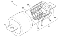
- a fuse element 51 incorporated in the in-vehicle fuse 50 of FIG. 10 is known (for example, there are those described in Patent Document 1 and Patent Document 2 as other similar uses). .)
- the in-vehicle fuse 50 is configured such that a fuse element 51 is housed in a cylindrical casing 52 and arc-extinguishing sand 53 is sealed between the fuse element 51 and the cylindrical casing 52.
- the fuse element 51 located at the center of the casing 52 has terminal portions 54 protruding from both end portions of the cylindrical casing 52. In order to set a large rated current, there is a predetermined distance between the terminal portions 54 and 54. Are integrally connected by four elements 55... 55 arranged in parallel with each other.
- FIG. 11 There are various methods for manufacturing this type of fuse element 51.
- the four elongated elements 55 in which the narrow holes 56 are punched to form the narrow fused portions 57 between the small holes 56 are prepared separately, and the element 55 is formed in the cutout groove 54 a of the terminal portion 54.
- Both end portions 55a and 55a are bent and locked, and the locking portions are fixed by means such as soldering or brazing.
- the terminal portion 54 is at least cut-off ⁇ cut ⁇ bend ⁇ cut the notch 54a until the element 55 is soldered to the terminal portion 54.
- the element 55 must be subjected to many processes such as raising, and at least the element 55, such as plate cutting ⁇ cutting ⁇ formation of the melted portion 57 (punching operation of the small hole 56) ⁇ folding operation of both end portions 55a, etc. It had to go through many manufacturing processes.
- a first problem is to provide a fuse element that can greatly improve productivity and improve cost by improving the manufacturing process.
- a second problem is to provide a fuse element that is unlikely to be damaged, such as cracking or burning, due to heat generated from the element when the fuse element is normally energized.
- a fuse element according to the present invention has terminal portions located at both ends connected by a plurality of elements arranged in parallel at a predetermined adjacent interval, and a substantially central portion of the element.
- terminal portions are arranged in parallel in the first invention is a broad concept including that the terminal portions are “arranged in parallel”.
- one metal plate punched into a predetermined shape and bent into a predetermined three-dimensional shape does not necessarily refer to a fuse element obtained only by a punching process and a bending process. Of course, there are various steps necessary to manufacture the fuse element, such as the thickness adjustment process, the extension process, and the inspection process performed after the bending process. It is.
- the one formed by bending into a predetermined three-dimensional shape refers to a final three-dimensional shape formed by bending through the above-described steps. Specifically, it means a three-dimensional shape that is compactly folded in order to easily accommodate the fuse element in the cylindrical casing.
- This three-dimensional shape is not particularly limited, and includes any shape.
- the cross-sectional shape of the melted portion may be substantially “self” shape, substantially “Z” shape, square, circular shape, etc., and these correspond to Embodiments 1 to 4 described later, respectively.
- the shape and form of the “terminal part” are not particularly limited, and various types of forms such as a blade-like terminal part and a box-shaped terminal part (plug-in type terminal part) surrounding the terminal at the connection destination are used. Things are included.
- the “element” in the present invention is a conductive metal portion that connects the terminal portions located at both ends, and when an unintended high current flows through the element in its substantially central portion. It includes a fusing part for quickly interrupting the circuit.
- the “melting part” refers to a substantially central part of the element.
- the shape and form are not particularly limited in the present invention.
- the cross-sectional area is made narrow, or the upper part of the narrow part or the vicinity thereof is made of, for example, tin, silver, lead, nickel, or an alloy thereof. Also included are deposits of low melting point metals.
- the material of the “terminal portion” and “element” may be a conductive metal.
- a single metal plate is punched into a predetermined shape, and a predetermined element required as a fuse element is obtained. Since it is formed into a three-dimensional shape, copper or an alloy thereof having both conductivity, bendability and spreadability is preferable.
- the terminal portion and the element with the same metal (base material), and at least the above-mentioned “element” is punched out into a predetermined shape from a single metal plate and has a predetermined three-dimensional shape. What is necessary is just to bend and shape to a target shape.
- a fastening metal fitting such as a screw, bolt or nut
- a fastening metal fitting such as a screw, bolt or nut
- predetermined shape in “punching into a predetermined shape” means “development shape” of the fuse element base material before bending, and the specific shape is the fuse shape. It is specified according to the application, type of fuse element, required rated current, etc.
- the shape of the developed view of such a fuse element is preferably punched from a single metal plate after cutting with a push tool having a cutting edge corresponding to the developed view, but of course, it is contrary to the process omission. You may punch by dividing the process for each terminal, element, fusing part, etc.
- second invention punch out all of the terminal portion and the plurality of elements from a single metal plate into a predetermined development shape and bend it into a predetermined three-dimensional shape.
- this invention After passing through such a punching molding process and a bending molding process, a plurality of elements are arranged in parallel with each other at predetermined adjacent intervals between the terminal portions, so that a parallel circuit of a fusing portion is formed between the terminal portions.
- a fuse element is obtained (hereinafter, this invention is referred to as “third invention”).
- the plurality of elements are preferably bent in a direction intersecting the terminal portion direction, and all the elements are preferably folded in the terminal portion direction (hereinafter, this invention is referred to as “fourth invention”). .)
- the relationship between “the bending process is performed in a direction intersecting the terminal portion direction” in the fourth invention and the “bending molding into a predetermined three-dimensional shape” in the first invention described above is as follows.
- the bending process of the fourth invention shows a specific one of the plurality of processes.
- a linear or curved fold line may be provided, and the fold may be bent along this fold line.
- the relationship with “bending molding into a predetermined three-dimensional shape” in the first invention is the final shape of the first invention. It shows a specific one of a plurality of steps required for processing. The reason why all the elements are folded in the direction of the terminal portion is to allow the element to absorb the thermal expansion in the direction of the terminal portion due to the temperature rise when the element is energized.
- the fuse element according to the present invention has a width of the element at a position away from the element located at the center in a state where a plurality of elements are bent into a predetermined three-dimensional shape. It is preferable to make it narrower than the width of the element located at the center (hereinafter, this invention is referred to as “fifth invention”).
- all or some of the plurality of elements constituting the fuse element of the fifth invention described above are folded in the direction of the terminal portion, and the fusing portion of the element at a position away from the element located at the center is provided. Only the fusing width may be narrower than the fusing width of the fusing portion of the element located at the center (hereinafter, this invention is referred to as “sixth invention”).
- the first to sixth inventions are “manufacturing inventions” called “fuse elements”, but there are two manufacturing processes called “punching process” and “bending molding process” in the invention. In other words, it is a so-called “product-by-process claim” invention, and includes the above two steps as essential constituent elements of the present invention.
- the plurality of elements including the fusing part are obtained by punching a single metal plate into a predetermined shape and bending it into a predetermined three-dimensional shape. Unlike the element 51 of the conventional fuse element 50 described above, it is not necessary to separately manufacture a pair of terminal portions and four elements including a fusing portion in advance, and both members can be molded simultaneously.
- the manufacturing process is greatly simplified (the process is omitted), mass production is possible without requiring the skill of an operator, and consequently the fuse element of the present invention.
- the productivity of fuses that incorporate s is greatly improved.
- the fuse element of the first invention since the parallel circuit of the fusing part is formed between the pair of terminal parts, the fusing current is divided, and thus the arc energy can be suppressed.
- the members of both the terminal portion and the plurality of elements are formed by bending a single metal plate into a predetermined shape and bending it into a predetermined three-dimensional shape. In addition to the effect, it is possible to obtain a fuse element in which productivity and significant cost reduction are further realized.
- a fuse element in which a parallel circuit of an arbitrary number of fusing parts is formed between terminal parts can be easily manufactured at low cost.
- the fuse element of the fourth invention since all the elements are folded in the direction of the terminal portion, it is possible to sufficiently absorb the thermal expansion in the direction of the terminal portion due to the temperature rise when the element is energized. Accordingly, the fusing characteristics of the fuse element are improved, and the life of the fuse element is increased correspondingly.
- the width of the element located away from the element located at the center is narrower than the width of the element located at the center, and Since the element at a position away from the positioned element is bent in the direction intersecting the terminal portion direction, the distance from both ends in the width direction of all the elements to the inner wall surface of the casing becomes equal as a result. .
- the amount of arc-extinguishing sand filled from the end in the width direction of the element to the inner wall surface of the casing becomes uniform, improving arc extinguishing performance. Connected. Therefore, the damage to the inner wall surface of the casing due to the Joule heat generated during normal energization generated from the melted portion and the arc during melt cutting is reduced.
- fuse element of the sixth invention all or a part of the constituent elements of the fuse element of the fifth invention are folded in the direction of the terminal portion, so the heat in the direction of the terminal portion due to the temperature rise when the element is energized Can fully absorb expansion.
- the fusing width of the fusing part of the element located away from the element located in the center is narrower than the fusing width of the fusing part of the element located in the middle, as a result, the width direction of all the elements The distance from both ends to the inner wall surface of the casing becomes equal, and the same effect as in the fifth invention is obtained, and the amount of arc-extinguishing sand filled between the end portion of the element and the inner wall surface of the casing is equalized. The arc extinguishing performance is improved.
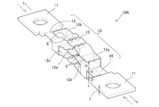
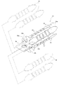
- FIG. 1 is an overall perspective view of a fuse element according to a first embodiment of the present invention.
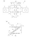
- FIG. 2A is a development view of the terminal portion and the element at the time when the punching process and the thickness adjusting process, which are intermediate processes in the manufacturing process of the fuse element of FIG. 1, are performed
- FIG. FIG. 3 is an enlarged cross-sectional view of the fuse element in FIG.
- FIG. 3 is an overall perspective view of a first modification of the fuse element of FIG.
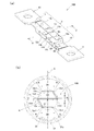
- FIG. 4 is an explanatory view of a second modification of the fuse element of FIG. 1, in which FIG. 4 (a) is an overall perspective view, and FIG. 4 (b) is a diagram of the fuse element of FIG. It is the expanded cross-sectional view seen from the line direction.
- FIG. 4 (a) is an overall perspective view
- FIG. 4 (b) is a diagram of the fuse element of FIG. It is the expanded cross-sectional view seen from the line direction.
- FIG. 4 (a) is an overall perspective view
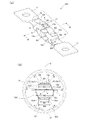
- FIG. 5 is an explanatory view of a third modification of the fuse element of FIG. 1, in which FIG. 5 (a) is an overall perspective view thereof, and FIG. 5 (b) is a view of the fuse element of FIG. It is the expanded cross-sectional view seen from the line direction.
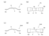
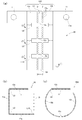
- FIG. 6A is a side view of the bore portion K in FIG. 5A
- FIG. 6B is a plan view thereof.
- 6C is a side view of another example of the bore portion K
- FIG. 6D is a plan view thereof.
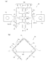
- FIG. 7A is a development view after the punching process in the manufacturing process of the fuse element according to the second embodiment of the present invention
- FIG. 7B is a diagram after the fuse element of FIG. FIG.
- FIG. 8 is an enlarged cross-sectional view as seen from the XX line direction in FIG.
- FIG. 8A is a development view after the punching process of the fuse element according to the third embodiment of the present invention
- FIG. 8B is a view after bending the fuse element of FIG. It is the expanded cross-sectional view seen from the YY line direction in a).
- FIG. 9A is a development view after the punching process of the fuse element according to the fourth embodiment of the present invention
- FIG. 9B is a view after bending the fuse element of FIG.
- FIG. 9C is an enlarged cross-sectional view as viewed from the direction of the ZZ line in FIG. 9A, and FIG. FIG.
- FIG. 10 is an overall perspective view of the conventional arc-extinguishing sand-containing in-vehicle fuse with a part of the casing portion broken.
- FIG. 11 is a perspective view illustrating an assembly process of a fuse element used in the in-vehicle fuse of FIG.
- FIG. 1 is an overall perspective view of a fuse element 10 according to an embodiment of the first invention described above.
- a fuse element 10 in FIG. 1, includes a pair of plate-like terminal portions 11, 11 located at both ends, an element 12 connecting the pair of terminal portions 11, 11, It is comprised by the fusing part located in the approximate center part 13.
- FIG. 1 a fuse element 10 according to the present embodiment includes a pair of plate-like terminal portions 11, 11 located at both ends, an element 12 connecting the pair of terminal portions 11, 11, It is comprised by the fusing part located in the approximate center part 13.
- the material of both the terminal portions 11 and 11 and the element 12 is made of copper or a copper alloy which is easily plastically deformed and has excellent bendability and spreadability in this embodiment. It doesn't matter.
- Each of the terminal portions 11 and 11 is formed with one mounting hole 11a to a mounting destination electrical device (not shown).
- the terminal portion 11 of the present embodiment is a single piece as shown in the figure, but when it is necessary to increase the thickness of the terminal portion 54 like the terminal portion 54 of FIG. These two terminal portions may be created, bent, and overlapped. The development of the terminal portion 54 in this case is, of course, created before bending.
- the element 12 has base end portions 15, 15 located at both ends, branch portions 12 a, 12 b branched from the respective base end portions 15, 15, and a space between each branch portion 12 a, 12 b. It is comprised from the element of 3 rows which consists of the lower part, the center part, and the upper elements 12c, 12d, and 12e connected mutually in parallel with H (FIG. 2 (a)). The widths of the three rows of elements 12c, 12d, and 12e are all the same, and the thickness t of the entire element 12 is thinner than the thickness T of the terminal portion 11 (t ⁇ T).
- the number of columns of the elements 12 is three, but of course, it may be two or four or more depending on the use, type, rated current, etc. of the fuse element.
- the base end portions 15 and 15 located at both ends of the element 12 are soldered to the adjacent terminal portion 11 by the soldering portion 14, so that both the terminal portions 11 and 11 and the element 12 Are integrally formed.
- connection method between the terminal portions 11 and 11 and the element 12 may be other means such as screwing as described above.
- the fuse element 10 according to the first embodiment is obtained by punching at least the element 12 out of a pair of terminal portions 11 and 11 and the elements 12 connected thereto into a predetermined shape from a single metal plate. It is formed by bending into a predetermined three-dimensional shape.
- the circular small holes 13 a are punched in two rows, for example, in two in a direction orthogonal to the terminal portions 11, 11 direction, so that the direction orthogonal to the terminal portions 11, 11 direction is obtained. A narrow cut portion is formed.
- the fusing part by the small hole method shown in the figure is an example, and it is needless to say that it may be that of another embodiment.
- FIG. 2A is a development view of the terminal portion 11 and the element 12 at the time when the punching process and the thickness adjusting process, which are intermediate processes of the manufacturing process of the fuse element 10 of FIG. 1, are performed
- FIG. FIG. 3 is an enlarged cross-sectional view of the fuse element 10 shown in FIG. 2A as viewed from the direction U-U in FIG. 1.
- Punching process Positioning of the cut copper plate using a device (not shown), automatic positioning is performed using a punching blade (not shown) such as a Thomson blade whose cutting edge has the same shape as the element 12 in FIG.
- Punching is performed with a punching machine (not shown), and the element 12 having the same shape as the element 12 in FIG. In this case, it is preferable to punch into the shape of the element 12 in FIG. 2A in one step as much as possible. However, if it is difficult, for example, the punching process of the small hole 13a is separated into a plurality of processes in order. You can punch it out. 3. Crease line forming step Although not essential, crease lines L1 and L2 are provided at the right branch portion 12a and the left branch portion 12b, which serve as a guide for the folding position. The element 12 in FIG. 2A represents the state at the completion of this process. 4).
- the left and right branch parts 12a and 12b of the element 12 are sequentially bent 90 degrees along the crease lines L1 and L2 in the directions of the circles 1 and 2 in the figure, and at the position of the UU line after the bending. As shown in FIG. 2B, the cross-sectional shape is bent so as to have a substantially “self” shape.
- the branch parts 12a and 12b on both sides on the lower element 12c side are counterclockwise by 90 degrees sequentially along the crease lines L1 and L2 of the branch part as shown in FIG. Bend twice.
- the lower elements 12c are formed which are arranged in parallel with each other at an interval of H adjacent to the central element 12d.
- the bifurcated portions 12a and 12b on the both sides of the upper element 12e are sequentially turned twice in the counterclockwise direction by 90 degrees along the crease lines L1 and L2 on the branched portions 12a and 12b. Bend it.
- the upper elements 12e are formed which are arranged in parallel with each other at a distance H adjacent to the central element 12d. 5.
- Soldering process with both terminal parts 11 and 11 A pair of terminal parts 11 and 11 prepared separately are soldered to the base end parts 15 and 15 of the element 12, respectively.
- the fuse element 10 having a substantially “self” three-dimensional shape is completed as the cross sections of the elements 12c, 12d, and 12e. Further, after that, necessary processing such as deposit processing (not shown) of the low melting point metal on the substantially central portion 13 described above and inspection is performed.
- necessary processing such as deposit processing (not shown) of the low melting point metal on the substantially central portion 13 described above and inspection is performed.
- the fuse element 10 of FIG. 1 the elements 12 arranged in parallel in three rows including the substantially central portion 13 are simultaneously punched into a predetermined shape from a single metal plate into a substantially “self” three-dimensional shape. Since it is bent, there is no need to separately prepare four elements 55 including the fusing part 57, unlike the element 55 of the conventional fuse element 51 described above with reference to FIGS. Further, when soldering to the terminal portion 54, there is no need for positioning work between the terminal portion 54 and the element 55, which is troublesome and requires skill.
- the element 12 including the substantially central portion 13 of the fuse element 10 according to the present invention has a higher degree of processing than both the terminal portions 11 and 11, so that the present invention is only required if the element 12 alone can be mass-produced by simple means. This goal is fully achieved.
- the manufacturing process is simplified, and the productivity of the fuse element and the fuse incorporating the fuse element is significantly improved.
- FIG. 3 is an overall perspective view of a fuse element 10A which is a first modification of the fuse element 10 shown in FIG.
- the fuse element 10A of the first modification is different from the fuse element 10 of FIG. 1 in that all of the terminal portions 11 and 11 and the element 12 are equivalent to a development view of the fuse element 10A of FIG. 3 from a single metal plate.
- the points 11 and 11 formed by punching the shape and bending it into the three-dimensional shape shown in the figure (second invention) and all three rows of elements 12c, 12d, and 12e constituting the element 12 by raising and lowering the temperature during use.
- the terminal portions 11 and 11 are folded in the direction (the fourth invention).
- the fuse element 10A in the embodiment of FIG. 3 is also bent in parallel with each other so that the adjacent intervals of the three rows of elements 12c, 12d, and 12e are H between the terminal portions 11 and 11, similarly to the fuse element 10 of FIG. As a result of the formation, a parallel circuit of three rows of substantially central portions 13 is formed between the terminal portions 11 and 11 (third invention).
- the number of the substantially central portions 13 arranged in parallel in the present embodiment is three rows, but it is needless to say that the number of rows may be four rows or more as in the third and fourth embodiments described later. It is.
- Punching process The plate material whose thickness has been adjusted is positioned by an automatic positioning punching machine (not shown), and the planar shape of the blade edge is punched by a punching machine having the entire shape of the fuse element 10A of FIG.
- crease lines L1 and L2 are attached to the surfaces of the left and right branch parts 12a and 12b. 5. Bending process The left and right branch portions 12a and 12b of the element 12 are sequentially bent in the direction of the arrow along the crease lines L1 and L2 in the manner described above, and the cross-sectional shape at the UU line position after the bending is shown in FIG. ) And is formed into a substantially three-dimensional shape of “self”. 6). Element folding process In order to absorb thermal expansion in the direction of the terminals 11 and 11 of the element 12 during the temperature rise and fall, the lower, middle and upper elements 12c, 12d and 12e are bent along the crease line S (FIG. 3). As shown in FIG. If possible, this step may be performed simultaneously with the bending step.
- the base end portions 15 and 15 of the element 12 are simultaneously punched with the terminal portion 11 connected thereto.
- the manufacturing process is further simplified and the productivity is dramatically improved compared to the fuse element 10 of FIG.
- the elements 12c, 12d, and 12e are bent in a direction intersecting the terminal portions 11 and 11, and each element is folded in the terminal portions 11 and 11, so that the temperature rises and falls during use.
- the thermal expansion and thermal contraction in the terminal portions 11 and 11 directions can be absorbed. Therefore, the life of the fuse element is extended by the amount of absorption of thermal expansion (in the direction of the solid line arrow in the figure) and thermal contraction (in the direction of the dashed line arrow in the figure).
- FIG. 4 is an explanatory diagram of a fuse element 10B according to a second modification of the fuse element 10 of FIG. 1, in which FIG. 4 (a) is an overall perspective view, and FIG. 4 (b) is FIG. 5 is an enlarged cross-sectional view of the fuse element 10B of (a) as viewed from the direction of the line VV passing through the small hole 13a of the substantially central portion 13.
- FIG. 4 (a) is an overall perspective view
- FIG. 4 is an explanatory diagram of a fuse element 10B according to a second modification of the fuse element 10 of FIG. 1, in which FIG. 4 (a) is an overall perspective view, and FIG. 4 (b) is FIG. 5 is an enlarged cross-sectional view of the fuse element 10B of (a) as viewed from the direction of the line
- the second modified example has two flat plates in the vertical position in a state where the cross-sectional shape at the substantially central portion 13 is bent into a substantially “self” shape.
- the width W1 of each of the elements 12c and 12e is narrower than the width W2 of the central plate-like element 12d (W1 ⁇ W2), so that the width direction of each of the lower element 12c and the upper element 12e in the substantially central portion 13 is Distances (shortest distance) R from a total of six fusing parts obtained by adding both end parts 12d1, 12d1 in the substantially central part 13 of the central element 12d to both end parts 12c1, 12c1, 12e1, 12e1 R, R, R, R, and R are all equal.
- the adjacent interval H between the three elements 12c, 12d, and 12e is made equal, and the arrangement of the lower element 12c and the upper element 12e is distributed with respect to the center line C.
- the fuse element 10B of the second modified example from both end portions 12c1, 12c1, 12d1, 12d1, 12e1, 12e1 at the substantially central portions 13, 13, 13 of all the elements 12c, 12d, 12e, Since the distances R, R, R, R, R, and R to the casing inner wall surface 52a are all equal, the fuse element 10B can be easily accommodated in the casing 52, and the elements 12c, 12d, and 12e are abbreviated.
- the thermal effects at the time of energization and fusing given to the inner wall surface 52a of the casing 13, 13, 13 are equalized.
- the casing inner wall surface 52a is less susceptible to the thermal damage from the substantially central portions 13, 13, and 13 that are the fusing portions of any of the elements 12c, 12d, and 12e, and the life of the entire fuse element is increased. There is an effect.
- FIG. 5 is an explanatory diagram of a fuse element 10C according to a third modification of the fuse element 10 of FIG. 1, in which FIG. 5 (a) is an overall perspective view, and FIG. 5 (b) is FIG. FIG. 4 is an enlarged cross-sectional view of the fuse element 10 ⁇ / b> C of (a) as viewed from the direction of the WW line passing through the small hole 13 a in the substantially central portion 13.
- the fuse element 10C according to the third modification includes all of the constituent elements 12c, 12d, and 12e of the fuse element 10B of FIG. 4A according to the second modification described above.
- the terminal portions 11 and 11 are folded in the direction.
- the fuse element 10 ⁇ / b> C is entirely displaced upward from the center point O of the casing 52 by the amount of displacement e by the amount of folding.
- both end portions 12e1 and 12e1 of the substantially central portion 13 of the upper element 12e and both end portions 12d1 and 12d1 of the substantially central portion 13 of the central element 12d protrude from the circle P, and are formed on the casing inner wall surface 52a. Because of the approach, the casing inner wall surface 52a is susceptible to thermal damage from these ends.
- the third modified example is formed in the upper element 12e protruding from the circle P and the opposite end portions 12d1, 12d1, 12e1, 12e1 of the substantially central portion 13 of the central element 12d (cutout portions). K is provided to cut out the protruding portion, and the lower element 12c is slightly pushed downward in the drawing to thereby end both ends 12c1, 12c1 at the substantially central portions 13, 13, 13 of all the elements 12c, 12d, 12e. , 12d1, 12d1, 12e1, 12e1 are positioned on a circle P centered on the center point O of the casing 52.
- the shape of the punched portion K has a width W1 at the position of the substantially central portion 13 of the upper element 12e as shown in the side view of FIG. 6A and the plan view of FIG. 6B.
- the two parallel straight lines are narrower than the width W3 of the branch portions 12a and 12b.
- both side surfaces may be formed in a circular arc shape. The same applies to the lower and central elements 12c and 12d.
- the distance from the end of the element to the inner wall surface of the case can be adjusted depending on whether the shape to be folded in the direction of the terminal is a simple bend or a curve.
- the shape will also change.
- thermal expansion in the direction of the terminal portions 11 and 11 due to temperature rise and fall during use It has an effect that can cope with heat shrinkage.
- the fuse elements 10 to 10C according to the present invention described with reference to FIGS. 1 to 5 have a three-dimensional shape in which the shape of the cross section is substantially “self”.
- cross-sectional shape of the fuse element of the present invention can be bent into three-dimensional shapes having various cross-sectional shapes in addition to the substantially “self” shape.
- the fuse element 20 of the second embodiment is formed by bending the element 12A into a three-dimensional shape in which the cross-sectional shape of the element 12A is substantially “Z”.
- the fuse elements 10 and 10A of the first embodiment shown in FIGS. 1 and 2 have the folding lines L1 and L2 such that the lower elements 12c and 12b at the left and right branch portions 12a and 12b It was formed on the extension of the inner and outer surfaces 12c3 and 12e3 of the upper element 12e.
- the substantially “Z” cross-sectional shape of the second embodiment is such that the folding lines L3 and L4 of the fuse element 20 are connected to the lower elements 12c at the left and right branch portions 12a and 12b, respectively.
- the second embodiment is different from the first embodiment in that it is formed on the extension of the middle portion of the center element 12d and on the extension of the middle portion of the center element 12d and the upper element 12e.
- the lower element 12c is 135 ° from the central element 12d in the counterclockwise direction (circle 1 direction in FIG. 7B) around the folding line L3
- the upper element 12e is It can be formed by bending 135 ° in the counterclockwise direction (the two circles in the figure) from the central element 12d around the fold line L4.
- the lower element 12c and the upper element 12e in the second embodiment are arranged “parallel” at a predetermined adjacent interval H1, but the surface of the central element 12d is not parallel to the above two elements. Since it is inclined at 45 °, it is arranged in the “parallel” relationship defined in the first invention.
- the number of columns of the element 12A in the first embodiment is the same as that of the element 12A, but is further increased in a casing (not shown). There is an effect that it can be stored compactly.
- the fuse element 30 of the third embodiment is formed by bending so that the cross-sectional shape of the element is a three-dimensional shape of “square”.
- the three-dimensional shape of the substantially “square” is similar to the folding lines L3 and L4 of the fuse element 20 of the second embodiment described above with reference to FIG. It can be easily obtained by bending at bending lines L5, L6, L7 on the intermediate line between the elements 12f to 12i at 12j, 12k.
- the folding order is as follows. First, the folding line L5 at the center of the left and right branch parts 12j, 12k is bent by 90 °, and then, the folding lines L6, L7 on both sides are sequentially centered. It can be easily molded by bending inwardly in the direction of the arrow in the figure.
- the fuse element 30 of the third embodiment can be suitably stored in a casing (not shown) having a square cross-sectional shape.
- the fuse elements 40 and 40A have a square shape in cross section of the element 12C portion in FIG. , And formed by bending into a “substantially circular” three-dimensional shape.
- the position of the terminal portion 11 in the development view is located at the center in the longitudinal direction of the branch portions 12a, 12b, 12j, and 12k.
- the fuse elements 40 and 40A according to the fourth embodiment are different from the fuse element 20 according to the second embodiment in which the terminal portion 11 is located at the center of the element 12A. 11 is different in that the position of 11 is located at the uppermost part of the branch parts 12s and 12t.
- the fuse element 40 having a square cross-sectional shape in FIG. 9B has the folding lines L8 to L10 on the intermediate line between the elements 12o to 12r in each branch portion, as in the second and third embodiments. And can be easily formed by bending them in the order of 90 ° in the order of circle 1.
- the fuse element 40A having a substantially circular cross-sectional shape in FIG. 9C can be easily formed by gradually bending it in the arrow direction (counterclockwise direction) of the circle 1 in FIG. 9A. it can.
- fuse elements 40 and 40A of Embodiment 4 can also be suitably stored in a casing having a square or circular cross-sectional shape.
- the fuse element 40A having a substantially circular cross-sectional shape shown in FIG. 9C has a substantially equal distance from the substantially central portions 13, 13... To the casing inner wall surface 52a (not shown). There is an excellent effect that the damage received by the casing due to the Joule heat generated by the portion 13 is the lowest as compared with the other embodiments.
- fuse elements 10 to 40A of the first to fourth embodiments described above are merely examples, and the fuse element of the present invention is not limited to these elements without departing from the spirit of the present invention. Modifications and combinations are possible, and these modifications and combinations are also included in the scope of the present invention.
- the application of the fuse element according to the present invention is not limited to the in-vehicle fuse, and can be used for various applications. Of course, these fuses are also included in the technical scope of the present invention.
Landscapes
- Fuses (AREA)
- Engineering & Computer Science (AREA)
- Manufacturing & Machinery (AREA)
Abstract
Description
図1は、前述した第1発明の一実施形態に係るヒューズエレメント10の全体斜視図である。
<本発明のヒューズエレメント10の製造方法>
かかる図1のヒューズエレメント10の製造方法を次の図2を用いて工程順に説明する。
1.エレメント12の板取り工程
図示しない銅板(又は銅合金板)から、図2(a)の中のエレメント12の全体寸法よりも若干大きな寸法を有する板材を板取りする。
2.打ち抜き工程
板取りした銅板を図示しない装置により位置決めし、これに刃先形状が図2(a)のエレメント12と同一形状をした例えばトムソン刃のような抜き刃(不図示)を用いて、自動位置決め打抜機(不図示)でパンチングし、図2(a)のエレメント12と同一形状のエレメント12を打ち抜く。この場合、なるべく一工程で図2(a)のエレメント12の形状に打ち抜くのが好ましいが、困難な場合は、例えば小孔13aの打ち抜き工程は別工程にするなどして複数工程に分けて順次打ち抜いても良い。
3.折り目線形成工程
必須ではないが、右側分岐部12aと左側分岐部12bとに折り曲げ位置の目安となる折り目線L1、L2を付ける。図2(a)のエレメント12は、この工程完了時の状態を表したものである。
4.折り曲げ工程
エレメント12の左右の分岐部12a、12bを折り目線L1、L2に沿って、図中の丸1、丸2の矢印方向に順次、90°ずつ折り曲げ、折り曲げ後のU-U線位置における横断面形状が図2(b)に示したように、略「己」形の立体的形状になるように折り曲げる。
5.両端子部11、11との半田付け工程
別に準備した一対の端子部11、11をそれぞれエレメント12の基端部15、15に半田付けする。
<本発明の作用効果>
図1のヒューズエレメント10によれば、略中央部13を含む3列に並列に配置されたエレメント12を、一枚の金属板から所定形状に同時に打ち抜いて略「己」形状の立体的形状に折り曲げ成形するので、図10及び図11で前述した従来のヒューズエレメント51のエレメント55のように、溶断部57を含む4枚のエレメント55を別々に準備する必要が全くない。また、端子部54への半田付けに際して、面倒で熟練を要する、端子部54とエレメント55との位置決め作業も全く必要ない。
<本発明の変形例>
図3は、図1に示したヒューズエレメント10の第1変形例であるヒューズエレメント10Aの全体斜視図である。
1.板取り工程
図示しない銅板(又は銅合金板)から、図2(a)のヒューズエレメント10Aの展開図全体(すなわち端子部11、11とエレメント12、12・・・の全て)の外形寸法よりも若干大きな外形寸法を有する板材を板取りする。
2.エレメント12の厚み調整工程
前工程で板取りした銅板に対し、エレメント12に相当する部分のみを図示しない機械ハンマーで打ちならし、エレメント12の厚みtを端子部11の厚みTよりも薄く(t<T)加工する(つまり一種のエンボス加工)。
3.打ち抜き工程
厚み調整を終えた板材を図示しない自動位置決め打抜機に位置決めし、刃先の平面形状が図2(a)のヒューズエレメント10Aの全体形状を刃型とする打抜機でパンチングし、図2(a)のエレメント12の基端部15、15に端子部11、11が接続された状態のヒューズエレメント10Aの展開図相当形状の板材を打ち抜く。この場合も、なるべく一工程で図2(a)のエレメント12の基端部15、15に端子部11、11が接続された状態の形状に打ち抜くのが好ましいが、困難な場合は複数工程に分けて順次打ち抜く。
4.折り目線形成工程
必要に応じ、左右の分岐部12a、12bの表面に折り目線L1、L2を付ける。
5.折り曲げ工程
エレメント12の左右の分岐部12a、12bを前述した要領で折り目線L1、L2に沿って、順次、矢印方向に折り曲げ、折り曲げ後のU-U線位置における横断面形状が図2(b)に示すように、略「己」形の立体的形状に折り曲げ成形する。
6.エレメントの折り縮め工程
昇降温時におけるエレメント12の端子部11、11方向への熱膨張を吸収するため、下部、中央部及び上部エレメント12c、12d、12eを折り目線S(図3)を屈曲線として略中央部13方向に折り縮める。この工程は可能であれば上記折り曲げ工程と同時に行っても良い。
ヒューズエレメント(本発明)
11 端子部
11a 取付孔
12~12C エレメント
12c 下部エレメント
12d 中央部エレメント
12e 上部エレメント
13 略中央部
13a 小孔
14 半田付け部
15 基端部
H 隣接間隔
K えぐり部
Claims (6)
- 両端部に位置する端子部が、所定の隣接間隔で並列に配置された複数のエレメントで接続され、該エレメントの略中央部に溶断部が設けられたヒューズエレメントであって、
前記両端部の端子部と前記複数のエレメントのうち、少なくとも前記エレメントは、一枚の金属板を所定の形状に打ち抜いて所定の立体的形状に折り曲げ成形したものであることを特徴とするヒューズエレメント。 - 前記端子部と前記複数のエレメントの全てが、一枚の金属板を所定の形状に打ち抜いて所定の立体的形状に折り曲げ成形したものであることを特徴とする請求項1記載のヒューズエレメント。
- 前記端子部間に、複数のエレメントを所定の隣接間隔で互いに平行に配置したことにより、前記端子部間に前記溶断部の並列回路が形成されていることを特徴とする請求項1又は請求項2に記載のヒューズエレメント。
- 前記複数のエレメントは、端子部方向と交差する方向に折り曲げ加工が施され、かつ、全てのエレメントが端子部方向に折り縮められていることを特徴とする請求項1~請求項3のうちのいずれか1項に記載のヒューズエレメント。
- 前記複数のエレメントは、中央に位置するエレメントから離れた位置にあるエレメントの幅が、前記中央に位置するエレメントの幅よりも狭いものであって、前記中央に位置するエレメントから離れた位置にあるエレメントが端子部方向と交差する方向に折り曲げ加工が施されていることを特徴とする請求項1~請求項3のうちのいずれか1項に記載のヒューズエレメント。
- 更に、前記複数のエレメントの全て、または一部のエレメントが、端子部方向に折り縮められていると共に、前記中央に位置するエレメントから離れた位置にあるエレメントの溶断部の溶断幅を、前記中央に位置するエレメントの溶断部の溶断幅よりも狭くしたことを特徴とする請求項5項に記載のヒューズエレメント。
Priority Applications (4)
| Application Number | Priority Date | Filing Date | Title |
|---|---|---|---|
| EP14748680.7A EP2955739B1 (en) | 2013-02-05 | 2014-01-29 | Fuse element |
| US14/764,345 US10297410B2 (en) | 2013-02-05 | 2014-01-29 | Fuse element |
| KR1020157023230A KR102085807B1 (ko) | 2013-02-05 | 2014-01-29 | 퓨즈 엘리먼트 |
| CN201480007200.8A CN104995712B (zh) | 2013-02-05 | 2014-01-29 | 熔丝元件 |
Applications Claiming Priority (2)
| Application Number | Priority Date | Filing Date | Title |
|---|---|---|---|
| JP2013020353A JP5952751B2 (ja) | 2013-02-05 | 2013-02-05 | ヒューズエレメントの製造方法 |
| JP2013-020353 | 2013-02-05 |
Publications (1)
| Publication Number | Publication Date |
|---|---|
| WO2014122898A1 true WO2014122898A1 (ja) | 2014-08-14 |
Family
ID=51299498
Family Applications (1)
| Application Number | Title | Priority Date | Filing Date |
|---|---|---|---|
| PCT/JP2014/000435 Ceased WO2014122898A1 (ja) | 2013-02-05 | 2014-01-29 | ヒューズエレメント |
Country Status (6)
| Country | Link |
|---|---|
| US (1) | US10297410B2 (ja) |
| EP (1) | EP2955739B1 (ja) |
| JP (1) | JP5952751B2 (ja) |
| KR (1) | KR102085807B1 (ja) |
| CN (1) | CN104995712B (ja) |
| WO (1) | WO2014122898A1 (ja) |
Cited By (3)
| Publication number | Priority date | Publication date | Assignee | Title |
|---|---|---|---|---|
| KR20160122602A (ko) * | 2015-04-14 | 2016-10-24 | 한국단자공업 주식회사 | 고전압 퓨즈 |
| CN111201583A (zh) * | 2017-09-25 | 2020-05-26 | 力特保险丝公司 | 多元件熔断器 |
| WO2020155080A1 (zh) * | 2019-02-01 | 2020-08-06 | 林平 | 防爆熔断管及其防爆熔断器和防爆熔断片 |
Families Citing this family (19)
| Publication number | Priority date | Publication date | Assignee | Title |
|---|---|---|---|---|
| JP2015156308A (ja) * | 2014-02-20 | 2015-08-27 | 矢崎総業株式会社 | ヒューズ |
| JP2017117565A (ja) * | 2015-12-22 | 2017-06-29 | 太平洋精工株式会社 | ヒューズの製造方法及びヒューズ |
| CN109411309B (zh) * | 2017-08-15 | 2020-03-31 | 比亚迪股份有限公司 | 熔断结构及熔断器 |
| CN113169381B (zh) | 2018-11-13 | 2024-08-06 | 瑞维安知识产权控股有限责任公司 | 用于非开关式高电压电源的配电系统 |
| DE112019005683B4 (de) * | 2018-11-13 | 2026-03-12 | Rivian Ip Holdings, Llc | Schnellbatterietrennsystem für Hochstromschaltungen |
| CN209461405U (zh) * | 2018-11-28 | 2019-10-01 | 库柏西安熔断器有限公司 | 熔断器、电动汽车用整车电路和电动汽车 |
| JP7018382B2 (ja) * | 2018-12-28 | 2022-02-10 | 太平洋精工株式会社 | ヒューズ |
| JP7256667B2 (ja) | 2019-03-28 | 2023-04-12 | デクセリアルズ株式会社 | 保護素子 |
| JP7433796B2 (ja) * | 2019-07-24 | 2024-02-20 | デクセリアルズ株式会社 | 保護素子 |
| JP7246097B2 (ja) * | 2020-02-19 | 2023-03-27 | 太平洋精工株式会社 | ヒューズ、及びヒューズの製造方法 |
| KR102461381B1 (ko) * | 2020-06-18 | 2022-11-01 | 한국단자공업 주식회사 | 퓨즈 엘리먼트 및 제조방법 |
| KR20220006328A (ko) | 2020-07-08 | 2022-01-17 | 한국단자공업 주식회사 | 퓨즈 엘리먼트 |
| US11764023B2 (en) * | 2020-10-26 | 2023-09-19 | Rivian Ip Holdings, Llc | Systems and methods for providing fluid-affected fuses |
| JP7539849B2 (ja) | 2021-02-19 | 2024-08-26 | デクセリアルズ株式会社 | 保護素子 |
| CN113506716B (zh) * | 2021-08-17 | 2025-07-08 | 西安中熔电气股份有限公司 | 一种固态预制灭弧模块 |
| US11875962B2 (en) | 2021-11-23 | 2024-01-16 | Littelfuse, Inc. | Protection device including multi-plane fusible element |
| JP7590379B2 (ja) * | 2022-07-19 | 2024-11-26 | 株式会社Soken | ヒューズ |
| KR20250121081A (ko) | 2023-01-20 | 2025-08-11 | 데쿠세리아루즈 가부시키가이샤 | 퓨즈 엘리먼트 및 보호 소자 |
| KR102622122B1 (ko) * | 2023-05-19 | 2024-01-09 | 스마트전자 주식회사 | 회로보호용 대전류 터미널 및 이를 이용한 회로 보호 시스템 |
Citations (8)
| Publication number | Priority date | Publication date | Assignee | Title |
|---|---|---|---|---|
| US4101860A (en) | 1976-05-20 | 1978-07-18 | Mcgraw-Edison Company | Protector for electric circuits |
| JPS5445333U (ja) * | 1977-09-06 | 1979-03-29 | ||
| DE2802050A1 (de) * | 1978-01-18 | 1979-07-19 | Allis Chalmers | Strombegrenzungs-sicherung |
| JPS57126040A (en) * | 1981-01-30 | 1982-08-05 | Yazaki Corp | Blade type fuse |
| JPS5891836U (ja) * | 1981-12-16 | 1983-06-21 | 株式会社三英社製作所 | 限流ヒユ−ズ |
| US5055817A (en) | 1990-10-03 | 1991-10-08 | Gould Inc. | Fuse with improved fusible element |
| JP2007059082A (ja) * | 2005-08-22 | 2007-03-08 | Fuji Electric Fa Components & Systems Co Ltd | ヒューズ |
| JP2012043573A (ja) * | 2010-08-17 | 2012-03-01 | Hinode Denki Seisakusho:Kk | 速断ヒューズ |
Family Cites Families (16)
| Publication number | Priority date | Publication date | Assignee | Title |
|---|---|---|---|---|
| GB813643A (en) * | 1956-05-04 | 1959-05-21 | Gen Electric Co Ltd | Improvements in or relating to elements for high rupturing capacity electrical fuses |
| US3291943A (en) * | 1966-12-13 | Time-lag fuse with ribbon fuse link folded in longitudinal and in transverse direction | ||
| GB190220483A (en) * | 1902-09-19 | 1903-07-23 | Oliver Leopold Peard | Improvements in Electric Safety Fuses. |
| US1290860A (en) | 1914-12-05 | 1919-01-07 | Westinghouse Electric & Mfg Co | Electric fuse. |
| DE741434C (de) * | 1939-11-18 | 1943-11-11 | Siemens Ag | Geschlossene Sicherung mit mehreren Schmelzleitern, insbesondere Niederspannungs-Hochleistungssicherung |
| NL258323A (ja) * | 1959-11-27 | |||
| US3189712A (en) * | 1963-02-18 | 1965-06-15 | Chase Shawmut Co | High interrupting capacity fuse |
| US3261952A (en) * | 1964-11-30 | 1966-07-19 | Chase Shawmut Co | Time-lag fuse with ribbon fuse link having two systems of bends |
| US3935553A (en) * | 1974-01-03 | 1976-01-27 | Kozacka Frederick J | Cartridge fuse for d-c circuits |
| JPS598280Y2 (ja) * | 1981-01-30 | 1984-03-14 | 矢崎総業株式会社 | ブレ−ドタイプヒユ−ズ |
| US5357234A (en) * | 1993-04-23 | 1994-10-18 | Gould Electronics Inc. | Current limiting fuse |
| US6194989B1 (en) * | 1996-06-27 | 2001-02-27 | Cooper Technologies Company | Fuse element having parallel strips |
| US5736918A (en) * | 1996-06-27 | 1998-04-07 | Cooper Industries, Inc. | Knife blade fuse having an electrically insulative element over an end cap and plastic rivet to plug fill hole |
| JP2010244921A (ja) * | 2009-04-08 | 2010-10-28 | Taiheiyo Seiko Kk | 高電圧用ヒューズ |
| US9196445B2 (en) * | 2011-07-05 | 2015-11-24 | Cooper Technologies Company | Electric fuse with torque restricting terminals |
| CN202332765U (zh) * | 2011-11-15 | 2012-07-11 | 浙江正泰机床电气制造有限公司 | 一种小体积大容量低压熔断器 |
-
2013
- 2013-02-05 JP JP2013020353A patent/JP5952751B2/ja active Active
-
2014
- 2014-01-29 KR KR1020157023230A patent/KR102085807B1/ko active Active
- 2014-01-29 US US14/764,345 patent/US10297410B2/en active Active
- 2014-01-29 WO PCT/JP2014/000435 patent/WO2014122898A1/ja not_active Ceased
- 2014-01-29 EP EP14748680.7A patent/EP2955739B1/en active Active
- 2014-01-29 CN CN201480007200.8A patent/CN104995712B/zh active Active
Patent Citations (8)
| Publication number | Priority date | Publication date | Assignee | Title |
|---|---|---|---|---|
| US4101860A (en) | 1976-05-20 | 1978-07-18 | Mcgraw-Edison Company | Protector for electric circuits |
| JPS5445333U (ja) * | 1977-09-06 | 1979-03-29 | ||
| DE2802050A1 (de) * | 1978-01-18 | 1979-07-19 | Allis Chalmers | Strombegrenzungs-sicherung |
| JPS57126040A (en) * | 1981-01-30 | 1982-08-05 | Yazaki Corp | Blade type fuse |
| JPS5891836U (ja) * | 1981-12-16 | 1983-06-21 | 株式会社三英社製作所 | 限流ヒユ−ズ |
| US5055817A (en) | 1990-10-03 | 1991-10-08 | Gould Inc. | Fuse with improved fusible element |
| JP2007059082A (ja) * | 2005-08-22 | 2007-03-08 | Fuji Electric Fa Components & Systems Co Ltd | ヒューズ |
| JP2012043573A (ja) * | 2010-08-17 | 2012-03-01 | Hinode Denki Seisakusho:Kk | 速断ヒューズ |
Non-Patent Citations (1)
| Title |
|---|
| See also references of EP2955739A4 * |
Cited By (5)
| Publication number | Priority date | Publication date | Assignee | Title |
|---|---|---|---|---|
| KR20160122602A (ko) * | 2015-04-14 | 2016-10-24 | 한국단자공업 주식회사 | 고전압 퓨즈 |
| KR102361578B1 (ko) | 2015-04-14 | 2022-02-11 | 한국단자공업 주식회사 | 고전압 퓨즈 |
| CN111201583A (zh) * | 2017-09-25 | 2020-05-26 | 力特保险丝公司 | 多元件熔断器 |
| CN111201583B (zh) * | 2017-09-25 | 2023-07-25 | 力特保险丝公司 | 多元件熔断器 |
| WO2020155080A1 (zh) * | 2019-02-01 | 2020-08-06 | 林平 | 防爆熔断管及其防爆熔断器和防爆熔断片 |
Also Published As
| Publication number | Publication date |
|---|---|
| CN104995712B (zh) | 2018-04-03 |
| KR102085807B1 (ko) | 2020-03-06 |
| KR20150115834A (ko) | 2015-10-14 |
| US20150371803A1 (en) | 2015-12-24 |
| EP2955739B1 (en) | 2021-09-08 |
| JP2014154234A (ja) | 2014-08-25 |
| US10297410B2 (en) | 2019-05-21 |
| EP2955739A1 (en) | 2015-12-16 |
| EP2955739A4 (en) | 2016-10-19 |
| JP5952751B2 (ja) | 2016-07-13 |
| CN104995712A (zh) | 2015-10-21 |
Similar Documents
| Publication | Publication Date | Title |
|---|---|---|
| JP5952751B2 (ja) | ヒューズエレメントの製造方法 | |
| JP5263733B2 (ja) | 金属板抵抗器 | |
| JP5682067B2 (ja) | ヒュージブルリンクブロックの回路構成用バスバー、ヒュージブルリンクブロック、およびヒュージブルリンクブロックの製造方法 | |
| JP6246764B2 (ja) | バスバー及びバッテリーモジュール | |
| CN102194620B (zh) | 熔丝以及熔丝的制造方法 | |
| JP6079302B2 (ja) | 電子部品及び電子制御装置 | |
| JP6199368B2 (ja) | ヒューズエレメント | |
| WO2017110160A1 (ja) | ヒューズの製造方法及びヒューズ | |
| JP7018382B2 (ja) | ヒューズ | |
| JP2021501979A (ja) | 電池積層体用の接触板を作製する方法、電池積層体用の接触板及び電池積層体 | |
| US10325745B2 (en) | Multiple element fuse | |
| WO2022014212A1 (ja) | ヒューズ、及びヒューズの製造方法 | |
| JP2006024825A (ja) | 電気部品 | |
| JP2015156308A (ja) | ヒューズ | |
| JP6643859B2 (ja) | シャント抵抗器の製造方法 | |
| JP2011066083A (ja) | プリント配線基板 | |
| KR20200019576A (ko) | 적어도 하나의, 특히 핀형상 접촉 요소를 전도체 플레이트의 전도성 경로에 부착하는 방법, 전도체 플레이트에 부착하기 위한 핀 헤더, 연결 조립체 | |
| JP7426088B2 (ja) | ヒューズ | |
| JP5942123B2 (ja) | 電気接続箱 | |
| JP2002343224A (ja) | ヒューズエレメント | |
| JP4682978B2 (ja) | 面実装型電流ヒューズおよびその製造方法 | |
| JP5603699B2 (ja) | ヒューズユニット | |
| JP2024056251A (ja) | 端子、電気部品接続構造、及び電気接続箱 | |
| JP2010027837A (ja) | 抵抗器 | |
| JP6057965B2 (ja) | ヒューズユニット及びヒューズユニット製造方法 |
Legal Events
| Date | Code | Title | Description |
|---|---|---|---|
| 121 | Ep: the epo has been informed by wipo that ep was designated in this application |
Ref document number: 14748680 Country of ref document: EP Kind code of ref document: A1 |
|
| WWE | Wipo information: entry into national phase |
Ref document number: 2014748680 Country of ref document: EP |
|
| WWE | Wipo information: entry into national phase |
Ref document number: 14764345 Country of ref document: US |
|
| NENP | Non-entry into the national phase |
Ref country code: DE |
|
| ENP | Entry into the national phase |
Ref document number: 20157023230 Country of ref document: KR Kind code of ref document: A |