WO2014123014A1 - データ処理装置、及びデータ処理方法 - Google Patents
データ処理装置、及びデータ処理方法 Download PDFInfo
- Publication number
- WO2014123014A1 WO2014123014A1 PCT/JP2014/051620 JP2014051620W WO2014123014A1 WO 2014123014 A1 WO2014123014 A1 WO 2014123014A1 JP 2014051620 W JP2014051620 W JP 2014051620W WO 2014123014 A1 WO2014123014 A1 WO 2014123014A1
- Authority
- WO
- WIPO (PCT)
- Prior art keywords
- parity check
- check matrix
- bits
- code
- parity
- Prior art date
- Legal status (The legal status is an assumption and is not a legal conclusion. Google has not performed a legal analysis and makes no representation as to the accuracy of the status listed.)
- Ceased
Links
Images


Classifications
-
- H—ELECTRICITY
- H03—ELECTRONIC CIRCUITRY
- H03M—CODING; DECODING; CODE CONVERSION IN GENERAL
- H03M13/00—Coding, decoding or code conversion, for error detection or error correction; Coding theory basic assumptions; Coding bounds; Error probability evaluation methods; Channel models; Simulation or testing of codes
- H03M13/03—Error detection or forward error correction by redundancy in data representation, i.e. code words containing more digits than the source words
- H03M13/05—Error detection or forward error correction by redundancy in data representation, i.e. code words containing more digits than the source words using block codes, i.e. a predetermined number of check bits joined to a predetermined number of information bits
- H03M13/11—Error detection or forward error correction by redundancy in data representation, i.e. code words containing more digits than the source words using block codes, i.e. a predetermined number of check bits joined to a predetermined number of information bits using multiple parity bits
- H03M13/1102—Codes on graphs and decoding on graphs, e.g. low-density parity check [LDPC] codes
- H03M13/1148—Structural properties of the code parity-check or generator matrix
- H03M13/116—Quasi-cyclic LDPC [QC-LDPC] codes, i.e. the parity-check matrix being composed of permutation or circulant sub-matrices
- H03M13/1165—QC-LDPC codes as defined for the digital video broadcasting [DVB] specifications, e.g. DVB-Satellite [DVB-S2]
-
- H—ELECTRICITY
- H03—ELECTRONIC CIRCUITRY
- H03M—CODING; DECODING; CODE CONVERSION IN GENERAL
- H03M13/00—Coding, decoding or code conversion, for error detection or error correction; Coding theory basic assumptions; Coding bounds; Error probability evaluation methods; Channel models; Simulation or testing of codes
- H03M13/03—Error detection or forward error correction by redundancy in data representation, i.e. code words containing more digits than the source words
- H03M13/05—Error detection or forward error correction by redundancy in data representation, i.e. code words containing more digits than the source words using block codes, i.e. a predetermined number of check bits joined to a predetermined number of information bits
- H03M13/11—Error detection or forward error correction by redundancy in data representation, i.e. code words containing more digits than the source words using block codes, i.e. a predetermined number of check bits joined to a predetermined number of information bits using multiple parity bits
- H03M13/1102—Codes on graphs and decoding on graphs, e.g. low-density parity check [LDPC] codes
- H03M13/1148—Structural properties of the code parity-check or generator matrix
- H03M13/1177—Regular LDPC codes with parity-check matrices wherein all rows and columns have the same row weight and column weight, respectively
-
- H—ELECTRICITY
- H03—ELECTRONIC CIRCUITRY
- H03M—CODING; DECODING; CODE CONVERSION IN GENERAL
- H03M13/00—Coding, decoding or code conversion, for error detection or error correction; Coding theory basic assumptions; Coding bounds; Error probability evaluation methods; Channel models; Simulation or testing of codes
- H03M13/03—Error detection or forward error correction by redundancy in data representation, i.e. code words containing more digits than the source words
- H03M13/033—Theoretical methods to calculate these checking codes
- H03M13/036—Heuristic code construction methods, i.e. code construction or code search based on using trial-and-error
-
- H—ELECTRICITY
- H03—ELECTRONIC CIRCUITRY
- H03M—CODING; DECODING; CODE CONVERSION IN GENERAL
- H03M13/00—Coding, decoding or code conversion, for error detection or error correction; Coding theory basic assumptions; Coding bounds; Error probability evaluation methods; Channel models; Simulation or testing of codes
- H03M13/25—Error detection or forward error correction by signal space coding, i.e. adding redundancy in the signal constellation, e.g. Trellis Coded Modulation [TCM]
- H03M13/255—Error detection or forward error correction by signal space coding, i.e. adding redundancy in the signal constellation, e.g. Trellis Coded Modulation [TCM] with Low Density Parity Check [LDPC] codes
-
- H—ELECTRICITY
- H03—ELECTRONIC CIRCUITRY
- H03M—CODING; DECODING; CODE CONVERSION IN GENERAL
- H03M13/00—Coding, decoding or code conversion, for error detection or error correction; Coding theory basic assumptions; Coding bounds; Error probability evaluation methods; Channel models; Simulation or testing of codes
- H03M13/27—Coding, decoding or code conversion, for error detection or error correction; Coding theory basic assumptions; Coding bounds; Error probability evaluation methods; Channel models; Simulation or testing of codes using interleaving techniques
- H03M13/2703—Coding, decoding or code conversion, for error detection or error correction; Coding theory basic assumptions; Coding bounds; Error probability evaluation methods; Channel models; Simulation or testing of codes using interleaving techniques the interleaver involving at least two directions
- H03M13/2707—Simple row-column interleaver, i.e. pure block interleaving
-
- H—ELECTRICITY
- H03—ELECTRONIC CIRCUITRY
- H03M—CODING; DECODING; CODE CONVERSION IN GENERAL
- H03M13/00—Coding, decoding or code conversion, for error detection or error correction; Coding theory basic assumptions; Coding bounds; Error probability evaluation methods; Channel models; Simulation or testing of codes
- H03M13/27—Coding, decoding or code conversion, for error detection or error correction; Coding theory basic assumptions; Coding bounds; Error probability evaluation methods; Channel models; Simulation or testing of codes using interleaving techniques
- H03M13/2703—Coding, decoding or code conversion, for error detection or error correction; Coding theory basic assumptions; Coding bounds; Error probability evaluation methods; Channel models; Simulation or testing of codes using interleaving techniques the interleaver involving at least two directions
- H03M13/271—Row-column interleaver with permutations, e.g. block interleaving with inter-row, inter-column, intra-row or intra-column permutations
-
- H—ELECTRICITY
- H03—ELECTRONIC CIRCUITRY
- H03M—CODING; DECODING; CODE CONVERSION IN GENERAL
- H03M13/00—Coding, decoding or code conversion, for error detection or error correction; Coding theory basic assumptions; Coding bounds; Error probability evaluation methods; Channel models; Simulation or testing of codes
- H03M13/29—Coding, decoding or code conversion, for error detection or error correction; Coding theory basic assumptions; Coding bounds; Error probability evaluation methods; Channel models; Simulation or testing of codes combining two or more codes or code structures, e.g. product codes, generalised product codes, concatenated codes, inner and outer codes
- H03M13/2906—Coding, decoding or code conversion, for error detection or error correction; Coding theory basic assumptions; Coding bounds; Error probability evaluation methods; Channel models; Simulation or testing of codes combining two or more codes or code structures, e.g. product codes, generalised product codes, concatenated codes, inner and outer codes using block codes
-
- H—ELECTRICITY
- H03—ELECTRONIC CIRCUITRY
- H03M—CODING; DECODING; CODE CONVERSION IN GENERAL
- H03M13/00—Coding, decoding or code conversion, for error detection or error correction; Coding theory basic assumptions; Coding bounds; Error probability evaluation methods; Channel models; Simulation or testing of codes
- H03M13/35—Unequal or adaptive error protection, e.g. by providing a different level of protection according to significance of source information or by adapting the coding according to the change of transmission channel characteristics
- H03M13/356—Unequal error protection [UEP]
-
- H—ELECTRICITY
- H03—ELECTRONIC CIRCUITRY
- H03M—CODING; DECODING; CODE CONVERSION IN GENERAL
- H03M13/00—Coding, decoding or code conversion, for error detection or error correction; Coding theory basic assumptions; Coding bounds; Error probability evaluation methods; Channel models; Simulation or testing of codes
- H03M13/61—Aspects and characteristics of methods and arrangements for error correction or error detection, not provided for otherwise
- H03M13/615—Use of computational or mathematical techniques
- H03M13/616—Matrix operations, especially for generator matrices or check matrices, e.g. column or row permutations
-
- H—ELECTRICITY
- H04—ELECTRIC COMMUNICATION TECHNIQUE
- H04L—TRANSMISSION OF DIGITAL INFORMATION, e.g. TELEGRAPHIC COMMUNICATION
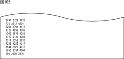
- H04L1/00—Arrangements for detecting or preventing errors in the information received
- H04L1/004—Arrangements for detecting or preventing errors in the information received by using forward error control
- H04L1/0056—Systems characterized by the type of code used
- H04L1/0057—Block codes
-
- H—ELECTRICITY
- H04—ELECTRIC COMMUNICATION TECHNIQUE
- H04L—TRANSMISSION OF DIGITAL INFORMATION, e.g. TELEGRAPHIC COMMUNICATION
- H04L1/00—Arrangements for detecting or preventing errors in the information received
- H04L1/004—Arrangements for detecting or preventing errors in the information received by using forward error control
- H04L1/0056—Systems characterized by the type of code used
- H04L1/0071—Use of interleaving
-
- H—ELECTRICITY
- H03—ELECTRONIC CIRCUITRY
- H03M—CODING; DECODING; CODE CONVERSION IN GENERAL
- H03M13/00—Coding, decoding or code conversion, for error detection or error correction; Coding theory basic assumptions; Coding bounds; Error probability evaluation methods; Channel models; Simulation or testing of codes
- H03M13/03—Error detection or forward error correction by redundancy in data representation, i.e. code words containing more digits than the source words
- H03M13/05—Error detection or forward error correction by redundancy in data representation, i.e. code words containing more digits than the source words using block codes, i.e. a predetermined number of check bits joined to a predetermined number of information bits
- H03M13/13—Linear codes
- H03M13/15—Cyclic codes, i.e. cyclic shifts of codewords produce other codewords, e.g. codes defined by a generator polynomial, Bose-Chaudhuri-Hocquenghem [BCH] codes
- H03M13/151—Cyclic codes, i.e. cyclic shifts of codewords produce other codewords, e.g. codes defined by a generator polynomial, Bose-Chaudhuri-Hocquenghem [BCH] codes using error location or error correction polynomials
- H03M13/152—Bose-Chaudhuri-Hocquenghem [BCH] codes
Definitions
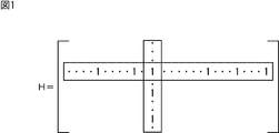
- LDPC code is characterized by the fact that the parity check matrix that defines the LDPC code is sparse.
- a sparse matrix is a matrix in which the number of “1” s in the matrix is very small (a matrix in which most elements are 0).
- Equation (1) and Equation (2) can be arbitrarily selected to indicate the number of “1” s in the vertical direction (column) and horizontal direction (row) of the parity check matrix H, respectively.
- variable node calculation of Expression (1) the message input from the edge (line connecting the variable node and the check node) to which the message is to be output, respectively.
- the computation range is 1 to d v -1 or 1 to d c -1.
- the check node calculation of equation (2) actually creates a table of function R (v 1 , v 2 ) shown in equation (3) defined by one output for two inputs v 1 and v 2 in advance. In addition, this is performed by using it continuously (recursively) as shown in Equation (4).
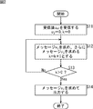
- step S12 the variable k is further incremented by “1”, and the process proceeds to step S13.
- step S13 it is determined whether or not the variable k is larger than a predetermined iterative decoding count C. If it is determined in step S13 that the variable k is not greater than C, the process returns to step S12, and thereafter the same processing is repeated.
- step S13 determines whether the variable k is larger than C. If it is determined in step S13 that the variable k is larger than C, the process proceeds to step S14, and a message v i as a decoding result to be finally output is obtained by performing the calculation shown in equation (5). And the LDPC code decoding process ends.
- equation (5) is performed using messages u j from all branches connected to the variable node.
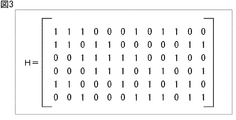
- the column weight is 3 and the row weight is 6, as in FIG.
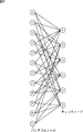
- FIG. 4 shows a Tanner graph of the check matrix H in FIG.
- the branch represents that the sign bit corresponding to the variable node has a constraint condition corresponding to the check node.
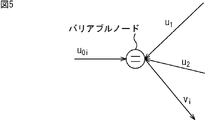
- FIG. 5 shows variable node calculation performed in the variable node.
- the message v i corresponding to the branch to be calculated is the variable node of the formula (1) using the messages u 1 and u 2 from the remaining branches connected to the variable node and the received value u 0i. It is obtained by calculation. Messages corresponding to other branches are obtained in the same manner.
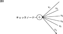
- FIG. 6 shows a check node operation performed at the check node.
- Equation (6) can be transformed into Equation (7).
- the message u j corresponding to the branch to be calculated is the messages v 1 , v 2 , v 3 , v 4 , v from the remaining branches connected to the check node. It is obtained by the check node calculation of Equation (7) using 5 . Messages corresponding to other branches are obtained in the same manner.
- ⁇ (x) and ⁇ ⁇ 1 (x) are mounted on hardware, they may be mounted using a LUT (Look Up Table), but both are the same LUT.
- DVB-S.2 ETSI EN 302 307 V1.2.1 (2009-08)
- the LDPC code is a symbol of quadrature modulation (digital modulation) such as QPSK (Quadrature Phase Shift Keying). (Symbolized), and the symbol is mapped to a signal point and transmitted.
- quadrature modulation digital modulation
- QPSK Quadrature Phase Shift Keying
- an LDPC code having a coding rate that can easily set a certain number of coding rates (for example, more than the number required for data transmission).
- the present technology has been made in view of such a situation, and is capable of providing an LDPC code having a good error rate.
- the first data processing apparatus or data processing method of the present technology converts an information bit into an LDPC code having a code length of 64,800 bits and a code rate of 2/30 based on a parity check matrix of an LDPC (Low Density Parity Check) code.
- LDPC Low Density Parity Check
- An encoding unit or encoding step for encoding wherein the LDPC code includes information bits and parity bits, and the parity check matrix includes an information matrix unit corresponding to the information bits and a parity matrix unit corresponding to the parity bits
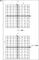
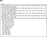
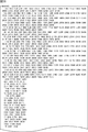
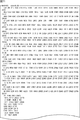
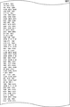
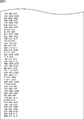
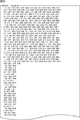
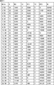
- the information matrix part is represented by a parity check matrix initial value table, and the parity check matrix initial value table is a table that represents the position of one element of the information matrix part for every 360 columns, 30 251 2458 3467 9897 12052 12191 15073 15949 16328 16972 17704 20672 22200 22276 25349 26106 28258 29737 30518 30951 32440 43031 46622 47113 52077 52609 52750 54295 55384 56954 57155 57853 59942 6985 7975 8681 10628 10866 13223 14882 18449 19570 24418 24538 24556 25926 26162 26947 28181 30049 33678 35497 37980
- the second data processing apparatus or the data processing method of the present technology includes a decoding unit that decodes an LDPC code having a code length of 64,800 bits and a code rate of 2/30 based on a parity check matrix of an LDPC (Low Density Parity Check) code Or the decoding step, wherein the LDPC code includes information bits and parity bits, and the parity check matrix includes an information matrix portion corresponding to the information bits and a parity matrix portion corresponding to the parity bits, and the information matrix Part is represented by a parity check matrix initial value table, the parity check matrix initial value table is a table that represents the position of one element of the information matrix part every 360 columns, 30 251 2458 3467 9897 12052 12191 15073 15949 16328 16972 17704 20672 22200 22276 25349 26106 28258 29737 30518 30951 32440 43031 46622 47113 52077 52609 52750 54295 55384 56954 57155
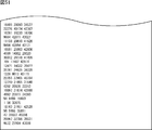
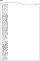
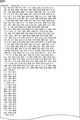
- the third data processing apparatus or data processing method of the present technology converts an information bit into an LDPC code having a code length of 64,800 bits and a code rate of 3/30 based on a parity check matrix of an LDPC (Low Density Parity Check) code.
- LDPC Low Density Parity Check
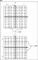
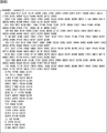
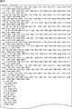
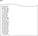
- a fourth data processing apparatus or data processing method includes a decoding unit that decodes an LDPC code having a code length of 64,800 bits and an encoding rate of 3/30 based on a parity check matrix of an LDPC (Low Density Parity Check) code Or the decoding step, wherein the LDPC code includes information bits and parity bits, and the parity check matrix includes an information matrix portion corresponding to the information bits and a parity matrix portion corresponding to the parity bits, and the information matrix Part is represented by a parity check matrix initial value table, the parity check matrix initial value table is a table that represents the position of one element of the information matrix part every 360 columns, 153 2939 6037 11618 12401 17787 18472 22673 25220 26245 29839 35106 36915 37622 37655 45425 55595 56308 56726 58286 146 160 9060 12867 16536 20818 31754 35546 36480 36698 563
- An encoding unit or encoding step for encoding wherein the LDPC code includes information bits and parity bits, and the parity check matrix includes an information matrix unit corresponding to the information bits and a parity matrix unit corresponding to the parity bits
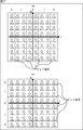
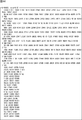
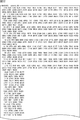
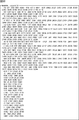
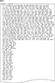
- the information matrix part is represented by a parity check matrix initial value table, and the parity check matrix initial value table is a table that represents the position of one element of the information matrix part for every 360 columns, 7248 8578 11266 16015 17433 18038 20159 20848 22164 23848 24516 25093 25888 28382 31701 33259 33540 34615 36428 38595 38683 38814 41592 44323 44522 44859 45857 48657 49686 53354 54260 54853 55069 55426 56127 715 1505 3314 5537 6377 6750 11039 11271 15840 16615 24045 24314 24435 26992 28524 28745 28935 32956 33359 3
- a sixth data processing apparatus or data processing method of the present technology includes a decoding unit that decodes an LDPC code having a code length of 64,800 bits and a coding rate of 4/30 based on a parity check matrix of an LDPC (Low Density Parity Check) code Or the decoding step, wherein the LDPC code includes information bits and parity bits, and the parity check matrix includes an information matrix portion corresponding to the information bits and a parity matrix portion corresponding to the parity bits, and the information matrix Part is represented by a parity check matrix initial value table, the parity check matrix initial value table is a table that represents the position of one element of the information matrix part every 360 columns, 7248 8578 11266 16015 17433 18038 20159 20848 22164 23848 24516 25093 25888 28382 31701 33259 33540 34615 36428 38595 38683 38814 41592 44323 44522 44859 45857 48657 49686 53354 54
- the seventh data processing device or data processing method of the present technology is based on an LDPC (Low Density Parity Check) code check matrix, and converts information bits into LDPC codes having a code length of 64,800 bits and a coding rate of 5/30.
- LDPC Low Density Parity Check
- An encoding unit or encoding step for encoding wherein the LDPC code includes information bits and parity bits, and the parity check matrix includes an information matrix unit corresponding to the information bits and a parity matrix unit corresponding to the parity bits
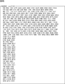
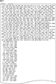
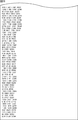
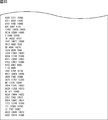
- the information matrix part is represented by a parity check matrix initial value table, and the parity check matrix initial value table is a table that represents the position of one element of the information matrix part for every 360 columns, 2035 5424 6737 8778 10775 15496 17467 21825 23901 27869 28939 29614 34298 34951 35578 37326 39797 44488 45293 45900 49239 53415 53900 2090 4170 12643 12925 13383 17659 23995 24520 25766 26042 26585 29531 31126 34856 43610 49028 49872 50309 50455 51586 52161 52207 53263 819 1629 5521 8339 8501 18663 22208 24768
- the ninth data processing apparatus or data processing method of the present technology converts an information bit into an LDPC code having a code length of 64,800 bits and a coding rate of 6/30 based on a parity check matrix of an LDPC (Low Density Parity Check) code.
- LDPC Low Density Parity Check
- An encoding unit or encoding step for encoding wherein the LDPC code includes information bits and parity bits, and the parity check matrix includes an information matrix unit corresponding to the information bits and a parity matrix unit corresponding to the parity bits
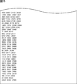
- the information matrix part is represented by a parity check matrix initial value table, and the parity check matrix initial value table is a table that represents the position of one element of the information matrix part for every 360 columns, 13033 14477 15028 17763 19244 20156 22458 24073 32202 32591 33531 33552 35823 41495 46351 49442 51612 44 66 8422 8760 14694 18768 20943 27806 29012 33594 36262 36820 40434 47704 49355 51729 51758 4233 16270 18958 20915 21313 27009 28249 33438 33855 34475 34541 37093 38835 42139 42169 44757 50122 82 10760
- the information bits are 64800 bits in code length and the coding rate is 2/30, 3/30, 4/30, 5/30, or And 6/30 LDPC code.
- the code length is 64800 bits and the coding rate is 2/30, 3/30, 4/30, 5/30, or 6
- the / 30 LDPC code is decoded.
- the LDPC code includes information bits and parity bits
- the parity check matrix includes an information matrix portion corresponding to the information bits and a parity matrix portion corresponding to the parity bits
- the information matrix portion is an initial parity check matrix.
- the parity check matrix initial value table is a table that represents the position of one element of the information matrix portion for every 360 columns.
- the parity check matrix initial value table with a coding rate of 3/30 is 153 2939 6037 11618 12401 17787 18472 22673 25220 26245 29839 35106 36915 37622 37655 45425 55595 56308 56726 58286 146 160 9060 12867 16536 20818 31754 35546 36480 36698 56314 56509 56837 57342 57373 57895 57947 58163 58202 58262 58 1555 10183 10446 12204 16197 16830 17382 19144 19565 21476 29121 41158 49953 51531 55642 57423 57587 57627 57974 120 9906 12466 21668 26856 27304 28451 29413 30168 31274 33309 33499 37486 38265 43457 50299 55218 56971 57059 58115 80 6649 9541 12490 14153 14346 19926 20677
- the parity check matrix initial value table with a coding rate of 4/30 is 7248 8578 11266 16015 17433 18038 20159 20848 22164 23848 24516 25093 25888 28382 31701 33259 33540 34615 36428 38595 38683 38814 41592 44323 44522 44859 45857 48657 49686 53354 54260 54853 55069 55426 56127 715 1505 3314 5537 6377 6750 11039 11271 15840 16615 24045 24314 24435 26992 28524 28745 28935 32956 33359 34964 36217 37546 38189 42599 44326 49694 54236 54779 55501 55543 55721 55865 55961 55966 55988 70 116 613 2482 6204 6608 7392 13585 14175 14228 17842 20004 20142 21324 22575 24443 24497 2539
- the data processing apparatus may be an independent apparatus or an internal block constituting one apparatus.
- This technology can provide an LDPC code with a good error rate.
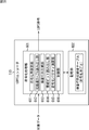
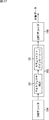
- FIG. 3 is a block diagram illustrating a configuration example of a transmission device 11.
- FIG. 3 is a block diagram illustrating a configuration example of a bit interleaver 116.
- FIG. It is a figure which shows a check matrix.
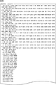
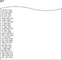
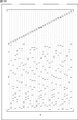
- Fig. 38 is a diagram illustrating an example of a parity check matrix initial value table with the code rate 2/30 and the code length 64800.
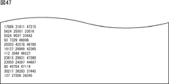
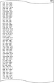
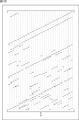
- Fig. 38 is a diagram illustrating an example of a parity check matrix initial value table with the code rate 3/30 and the code length 64800.
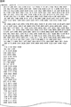
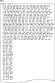
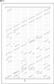
- Fig. 38] Fig. 38 is a diagram illustrating an example of a parity check matrix initial value table with the code rate 4/30 and the code length 64800.
- FIG. 38 is a diagram illustrating an example of a parity check matrix initial value table with the code rate 10/30 and the code length 64800.
- Fig. 38 is a diagram illustrating an example of a parity check matrix initial value table with the code rate 11/30 and the code length 64800.
- Fig. 38 is a diagram illustrating an example of a parity check matrix initial value table with the code rate 11/30 and the code length 64800.
- Fig. 38] Fig. 38 is a diagram illustrating an example of a parity check matrix initial value table with the code rate 12/30 and the code length 64800.
- FIG. 38 is a diagram illustrating an example of a parity check matrix initial value table with the code rate 16/30 and the code length 64800.
- Fig. 38 is a diagram illustrating an example of a parity check matrix initial value table with the code rate 16/30 and the code length 64800.
- Fig. 38 is a diagram illustrating an example of a parity check matrix initial value table with the code rate 17/30 and the code length 64800.
- Fig. 38] Fig. 38 is a diagram illustrating an example of a parity check matrix initial value table with the code rate 17/30 and the code length 64800.
- Fig. 38] Fig. 38 is a diagram illustrating an example of a parity check matrix initial value table with the code rate 17/30 and the code length 64800.
- FIG. 38 is a diagram illustrating an example of a parity check matrix initial value table with the code rate 21/30 and the code length 64800.
- Fig. 38 is a diagram illustrating an example of a parity check matrix initial value table with the code rate 22/30 and the code length 64800.
- Fig. 38 is a diagram illustrating an example of a parity check matrix initial value table with the code rate 22/30 and the code length 64800.
- Fig. 38] Fig. 38 is a diagram illustrating an example of a parity check matrix initial value table with the code rate 22/30 and the code length 64800.
- Fig. 38] Fig. 38 is a diagram illustrating an example of a parity check matrix initial value table with the code rate 22/30 and the code length 64800.
- FIG. 38 is a diagram illustrating an example of a parity check matrix initial value table with the code rate 27/30 and the code length 64800.
- Fig. 38 is a diagram illustrating an example of a parity check matrix initial value table with the code rate 27/30 and the code length 64800.
- Fig. 38 is a diagram illustrating an example of a parity check matrix initial value table with the code rate 27/30 and the code length 64800.
- Fig. 38] Fig. 38 is a diagram illustrating an example of a parity check matrix initial value table with the code rate 27/30 and the code length 64800.
- Fig. 38] Fig. 38 is a diagram illustrating an example of a parity check matrix initial value table with the code rate 27/30 and the code length 64800.
- FIG. 38 is a diagram illustrating an example of a parity check matrix initial value table with the code rate 28/30 and the code length 64800.
- Fig. 38 is a diagram illustrating an example of a parity check matrix initial value table with the code rate 28/30 and the code length 64800.
- Fig. 38 is a diagram illustrating an example of a parity check matrix initial value table with the code rate 28/30 and the code length 64800.
- Fig. 38] Fig. 38 is a diagram illustrating an example of a parity check matrix initial value table with the code rate 28/30 and the code length 64800.
- Fig. 38] Fig. 38 is a diagram illustrating an example of a parity check matrix initial value table with the code rate 28/30 and the code length 64800.
- FIG. 38 is a diagram illustrating an example of a parity check matrix initial value table with the code rate 29/30 and the code length 64800.
- Fig. 38 is a diagram illustrating an example of a parity check matrix initial value table with the code rate 29/30 and the code length 64800.
- Fig. 38 is a diagram illustrating an example of a parity check matrix initial value table with the code rate 29/30 and the code length 64800.
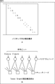
- Fig. 38] Fig. 38 is a diagram illustrating an example of a parity check matrix initial value table with the code rate 29/30 and the code length 64800. It is a figure which shows the example of the Tanner graph of the ensemble of a degree sequence that column weight is 3 and row weight is 6.
- FIG. 38 shows the example of the Tanner graph of the ensemble of a degree sequence that column weight is 3 and row weight is 6.
- FIG. 12 is a flowchart for describing processing performed by a QAM decoder 164, a bit deinterleaver 165, and an LDPC decoder 166. It is a figure which shows the example of the check matrix of a LDPC code. It is a figure which shows the matrix (conversion test matrix) which performed row substitution and column substitution to the check matrix.
- FIG. 3 is a block diagram illustrating a configuration example of an LDPC decoder 166.
- FIG. It is a figure explaining the process of the multiplexer 54 which comprises the bit deinterleaver 165.
- FIG. It is a figure explaining the process of the column twist deinterleaver.
- FIG. It is a block diagram which shows the 1st structural example of the receiving system which can apply the receiving device.
- FIG. 18 is a block diagram illustrating a configuration example of an embodiment of a computer to which the present technology is applied.
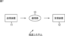
- FIG. 7 shows a transmission system to which the present technology is applied (a system is a logical collection of a plurality of devices, regardless of whether or not each component device is in the same housing). The structural example of embodiment is shown.
- the transmission system includes a transmission device 11 and a reception device 12.
- the transmission device 11 transmits (broadcasts) (transmits) a television broadcast program, for example. That is, the transmission device 11 encodes target data to be transmitted, such as image data and audio data as a program, into an LDPC code, for example, a satellite line, a terrestrial wave, a cable (wired line), or the like. It transmits via the communication path 13.
- target data to be transmitted such as image data and audio data as a program
- an LDPC code for example, a satellite line, a terrestrial wave, a cable (wired line), or the like. It transmits via the communication path 13.
- a burst error or erasure may occur in the communication path 13.
- D / U Desired to Undesired Ratio
- Desired main path power
- a burst error may occur due to the state of the wiring from the receiving unit (not shown) such as an antenna that receives a signal from the transmitting device 11 to the receiving device 12 on the receiving device 12 side or the instability of the power supply of the receiving device 12. May occur.
- the check node performs the check node calculation of Expression (7) using the message obtained by the variable node connected to the check node, so that a plurality of connected variable nodes ( When the number of check nodes in which the error (including erasure) of the code bits of the LDPC code corresponding to) simultaneously increases, the decoding performance deteriorates.
- the check node sends a message with an equal probability of a probability of 0 and a probability of 1 to all the variable nodes. return.
- a check node that returns an equiprobable message does not contribute to one decoding process (one set of variable node calculation and check node calculation), and as a result, requires a large number of repetitions of the decoding process. As a result, the decoding performance deteriorates, and the power consumption of the receiving apparatus 12 that decodes the LDPC code increases.
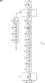
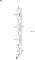
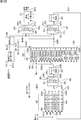
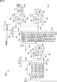
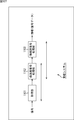
- FIG. 8 is a block diagram illustrating a configuration example of the transmission device 11 of FIG.
- one or more input streams (Input Streams) as target data are supplied to a Mode Adaptation / Multiplexer 111.
- the mode adaptation / multiplexer 111 performs processing such as mode selection and multiplexing of one or more input streams supplied thereto as necessary, and supplies the resulting data to a padder 112. .
- the BB scrambler 113 subjects the data from the padder 112 to BB scramble (Base-Band Scrambling), and supplies the resulting data to a BCH encoder (BCH encoder) 114.
- BCH encoder BCH encoder
- the BCH encoder 114 BCH-encodes the data from the BB scrambler 113, and supplies the resulting data to an LDPC encoder 115 as LDPC target data that is an LDPC encoding target.
- the LDPC encoder 115 performs LDPC encoding on the LDPC target data from the BCH encoder 114 according to a parity check matrix in which a parity matrix that is a part corresponding to the parity bits of the LDPC code has a staircase structure. Output LDPC code as information bits.
- the LDPC encoder 115 sets the LDPC target data to the LDPC (corresponding to the check matrix) defined in a predetermined standard such as DVB-S.2, DVB-T.2, or DVB-C.2.
- LDPC encoding is performed to encode a code, a predetermined LDPC code (corresponding to the parity check matrix), and the resulting LDPC code is output.
- the LDPC code defined in the DVB-S.2, DVB-T.2, and DVB-C.2 standards is an IRA (Irregular Repeat Accumulate) code, and the parity in the parity check matrix of the LDPC code
- the matrix has a staircase structure. The parity matrix and the staircase structure will be described later.
- IRA codes for example, “Irregular Repeat-Accumulate Codes,” H. Jin, A. Khandekar, and R. J. McEliece, in Proceedings of 2nd International Symposium on Turbo codes and Related Topics-8 , Sept. 2000.
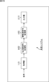
- the LDPC code output from the LDPC encoder 115 is supplied to the bit interleaver 116.
- the bit interleaver 116 performs bit interleaving described later on the LDPC code from the LDPC encoder 115, and supplies the LDPC code after the bit interleaving to a QAM encoder (QAM encoder) 117.
- QAM encoder QAM encoder
- the QAM encoder 117 maps the LDPC code from the bit interleaver 116 to a signal point representing one symbol of orthogonal modulation in units of one or more code bits (symbol unit) of the LDPC code and performs orthogonal modulation ( Multilevel modulation).
- the MISO / MIMO encoder 119 performs space-time coding on the data (symbol) from the time interleaver 118 and supplies it to a frequency interleaver 120.
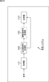
- the BCH encoder 121 is supplied with control data (signalling) for transmission control such as BB signaling (Base Band Signaling) (BB Header).
- BB signaling Basic Band Signaling
- the BCH encoder 121 performs BCH encoding on the control data supplied thereto in the same manner as the BCH encoder 114, and supplies the resulting data to the LDPC encoder 122.
- LDGM Low-Density Generation Matrix
- the number of information bits and the number of parity bits in the code bits of one LDPC code are referred to as information length K and parity length M, respectively, and one LDPC.
- the information length K and the parity length M for an LDPC code having a certain code length N are determined by the coding rate.
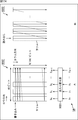
- the parity check matrix H is an M ⁇ N matrix with rows ⁇ columns. Then, the information matrix H A, becomes the matrix of M ⁇ K, the parity matrix H T is a matrix of M ⁇ M.
- DVB-S.2 shows a parity matrix H T of the parity DVB-T.2, and parity check matrix H of an LDPC code prescribed in DVB-C.2 standards.
- DVB-T.2 like parity matrix H T of the parity check matrix H of an LDPC code of which is specified in the Standard, as shown in FIG. 11, first element is, so to speak a matrix of step structure arranged stepwise (lower bidiagonal matrix).
- the row weight of the parity matrix H T is 1 for the first row and 2 for all the remaining rows.
- the column weight is 1 for the last column and 2 for all the remaining columns.
- LDPC codes of the check matrix H the parity matrix H T has a staircase structure can be using the check matrix H, readily produced.
- an LDPC code (one codeword), together represented by a row vector c, and column vector obtained by transposing the row vector is represented as c T. Further, in the row vector c which is an LDPC code, the information bit portion is represented by the row vector A, and the parity bit portion is represented by the row vector T.
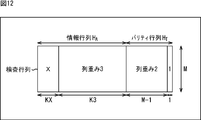
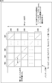
- FIG. 12 is a diagram for explaining a parity check matrix H of an LDPC code defined in a standard such as DVB-T.2.
- the column weight is X, and for the subsequent K3 column, the column weight is 3, and then For the M-1 column, the column weight is 2, and for the last column, the column weight is 1.
- KX + K3 + M-1 + 1 is equal to the code length N.
- FIG. 13 is a diagram showing the number of columns KX, K3, and M, and the column weight X for each coding rate r of the LDPC code defined in the DVB-T.2 standard and the like.
- Standards such as DVB-T.2 specify LDPC codes with code length N of 64800 bits and 16200 bits.
- LDPC code having a code length N of 64,800 bits 11 coding rates (nominal rates) 1/4, 1/3, 2/5, 1/2, 3/5, 2/3, 3 / 4, 4/5, 5/6, 8/9, and 9/10 are defined, and for an LDPC code having a code length N of 16200 bits, 10 coding rates 1/4, 1/3, 2/5, 1/2, 3/5, 2/3, 3/4, 4/5, 5/6, and 8/9 are specified.
- the code length N of 64800 bits is also referred to as 64k bits
- the code length N of 16200 bits is also referred to as 16k bits.
- the column weight on the head side (left side) tends to be large.
- the LDPC code corresponding to H the first code bit tends to be more resistant to errors (tolerant to errors), and the last code bit tends to be weaker to errors.
- FIG. 14 shows an example of arrangement of 16 symbols (corresponding signal points) on the IQ plane when 16QAM is performed by the QAM encoder 117 of FIG.
- a in FIG. 14 shows a 16QAM symbol of DVB-T.2.
- the 16 symbols are arranged so that the I direction ⁇ Q direction is a 4 ⁇ 4 square shape with the origin of the IQ plane as the center.
- FIG. 14B shows bit boundaries for each of 4 bits (hereinafter also referred to as symbol bits) y 0 to y 3 represented by a 16QAM symbol.
- the symbol bit y i represented by a symbol is more likely to be erroneous (lower error probability) the more symbols are away from the bit boundary, and more likely to be error (higher error probability) as there are more symbols near the bit boundary.
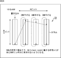
- One symbol bit of 64QAM can be expressed as bits y 0 , y 1 , y 2 , y 3 , y 4 , y 5 in order from the most significant bit.
- the 6 code bits of the LDPC code are the symbol bit y 0 no 6-bit to the symbol y 5.
- the most significant symbol bit y 0 and the second symbol bit y 1 are strong bits, and the third symbol bits y 2 and 4 th symbol bit y 3 has become a strong bit to the next.
- the fifth symbol bit y 4 and the sixth symbol bit y 5 are weak bits.
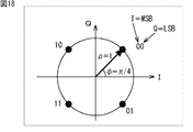
- FIG. 18 shows an arrangement of four symbols (corresponding signal points) on the IQ plane when a satellite channel is adopted as the communication path 13 (FIG. 7) and QPSK is performed by the QAM encoder 117 of FIG. It is a figure which shows the example, ie, the symbol of QPSK of DVB-S.2, for example.
- a symbol is mapped to one of four signal points on a circle with a radius ⁇ of 1 centered on the origin on the IQ plane.
- FIG. 19 shows an example of arrangement of 8 symbols on the IQ plane when a satellite channel is employed as the communication path 13 (FIG. 7) and 8PSK is performed by the QAM encoder 117 of FIG. 8, that is, for example, DVB It is a figure which shows the symbol of 8PSK of -S.2.
- a symbol has four signal points on the circumference of a circle with a radius of R 1 centered at the origin on the IQ plane, and a radius of R 2 (> R 1 ).
- the 12 signal points on the circumference of the circle are mapped to any one of 16 signal points in total.
- the ratio ⁇ between the radii R 2 and R 1 is different for each coding rate.
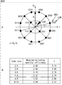
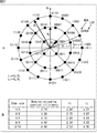
- FIG. 21 shows an example of arrangement of 32 symbols on the IQ plane when a satellite channel is employed as the communication path 13 (FIG. 7) and 32APSK is performed by the QAM encoder 117 of FIG. 8, that is, for example, DVB It is a figure which shows the symbol of -32 APSK of -S.2.
- 21A shows the arrangement of the 32APSK signal points of DVB-S.2.
- a symbol consists of four signal points on the circumference of a circle with a radius of R 1 centered at the origin on the IQ plane and a circle with a radius of R 2 (> R 1 ). 12 signal points on the circumference and 16 signal points on the circumference of the circle having a radius of R 3 (> R 2 ) are mapped to any one of 32 signal points in total.
- the ratio gamma 1 and radius R 2 and R 1 and the radius R 3 and the ratio gamma 2 and R 1 are different for each code rate.
- the LDPC code output from the LDPC encoder 115 includes a code bit that is resistant to errors and a code bit that is vulnerable to errors.
- the symbol bits of the orthogonal modulation symbols performed by the QAM encoder 117 include strong bits and weak bits.
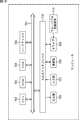
- FIG. 22 is a diagram for explaining the processing of the demultiplexer 25 in FIG.
- the memory 31 has a storage capacity for storing mb bits in the row (horizontal) direction and N / (mb) bits in the column (vertical) direction, and the LDPC supplied thereto The sign bit of the code is written in the column direction, read in the row direction, and supplied to the switching unit 32.
- m represents the number of code bits of an LDPC code that is one symbol
- b is a predetermined positive integer, which is a multiple used to multiply m by an integer.
- the demultiplexer 25 uses the sign bit of the LDPC code as a symbol (symbolizes), and the multiple b represents the number of symbols that the demultiplexer 25 obtains by so-called symbolization.
- FIG. 22A shows a configuration example of the demultiplexer 25 in the case where the modulation scheme is 64QAM or the like that maps symbols to any of 64 signal points. Therefore, the sign bit of the LDPC code that becomes one symbol The number of bits m is 6 bits.
- mb bits (6 bits in this case) of code bits are read from the memory 31 in the row direction, and the i-th bit from the most significant bit of the mb bits of code bits read from the memory 31 is read out.
- bit b i the 6-bit code bits read out from the memory 31 in the row direction are bits b 0 , It can be expressed as b 1 , b 2 , b 3 , b 4 , b 5 .
- FIG. 22B shows the first replacement method
- FIG. 22C shows the second replacement method
- FIG. 22D shows the third replacement method.
- the code bits of the LDPC code are written from the top to the bottom (column direction) of the columns constituting the memory 31. Is called.
- parity interleaving by the parity interleaver 23 in FIG. 9 will be described with reference to FIGS.
- FIG. 25 shows a parity matrix H T having a staircase structure and a Tanner graph corresponding to the parity matrix H T.
- Figure 26 illustrates a parity matrix H T of the parity check matrix H corresponding to the LDPC code after parity interleave to the parity interleaver 23 of FIG. 9 is performed.
- the information matrix H A of the parity check matrix H corresponding to the LDPC code defined in the DVB-S.2 standard and the like output from the LDPC encoder 115 has a cyclic structure.
- FIG. 27B shows processing performed by the demultiplexer 25 (FIG. 9) for the LDPC code of the conversion check matrix of FIG. 27A, that is, the LDPC code after parity interleaving.
- the modulation method is a method of mapping symbols to any of 16 signal points, such as 16APSK or 16QAM
- the four columns constituting the memory 31 of the demultiplexer 25 are subjected to parity interleaving.
- the sign bit of the LDPC code is written in the column direction.
- 4-bit code bits B 0 , B 1 , B 2 , and B 3 that are one symbol are code bits corresponding to 1 in any one row of the conversion check matrix of A in FIG.
- the variable nodes corresponding to the sign bits B 0 , B 1 , B 2 , and B 3 are connected to the same check node.
- the column twist interleaver 24 performs a process after parity interleaving from the parity interleaver 23 so that a plurality of code bits corresponding to 1 in any one row of the conversion check matrix are not included in one symbol. Column twist interleaving is performed to interleave the code bits of the LDPC code.
- FIG. 28 is a diagram for explaining column twist interleaving.
- FIG. 28 shows the memory 31 (FIGS. 22 and 23) of the demultiplexer 25.
- the memory 31 stores N / (mb) bits in the column (vertical) direction and has a storage capacity for storing mb bits in the row (horizontal) direction.
- Consists of The column twist interleaver 24 performs column twist interleaving by controlling the write start position when writing the code bits of the LDPC code in the column direction and reading in the row direction to the memory 31.
- a plurality of code bits, which are read as one symbol, are read out in the row direction by appropriately changing the write start position at which code bit writing is started for each of a plurality of columns.
- the sign bit corresponding to 1 in any one row of the conversion parity check matrix is prevented (a plurality of code bits corresponding to 1 in any one row of the parity check matrix are not included in the same symbol.
- the code bits of the LDPC code are rearranged).
- the column twist interleaver 24 writes the code bits of the LDPC code from the top to the bottom (column direction) of the four columns constituting the memory 31 (instead of the demultiplexer 25 in FIG. 22). Towards the direction column.
- the address at the top (top) position of each column is 0 and the address at each position in the column direction is expressed as an integer in ascending order
- the starting position of writing is the position where the address is 0, the second column (from the left) is the starting position of writing, the address is the position 2, and the third column is the starting position of writing.
- the address is at position 4, and for the fourth column, the write start position is the position at address 7.
- the writing start position is other than the position where the address is 0
- the writing start position After writing the sign bit to the lowest position, it returns to the beginning (position where the address is 0), and the writing start position. Writing up to the position immediately before is performed. Thereafter, writing to the next (right) column is performed.
- FIG. 29 shows the number of columns of the memory 31 necessary for column twist interleaving and the writing of LDPC codes of 11 coding rates defined in the DVB-T.2 standard and having a code length N of 64800. The address of the starting position is shown for each modulation method.
- the first column write start position is the address 0 position
- the second column write start position is the address 2 position
- the write start position of the second column is the position where the address is 4
- the write start position of the fourth column is the position where the address is 7.
- the memory 31 is arranged in the row direction according to FIG. It has 8 columns for storing 4 ⁇ 2 bits and stores 64800 / (4 ⁇ 2) bits in the column direction.
- the first column write start position is the address 0 position
- the second column write start position is the address 0 position
- the start position of the second column is the position where the address is 2
- the start position of the fourth column is the position where the address is 2
- the start position of the fifth column is the position where the address is 3.
- the position and the start position of the 6th column are the position where the address is 4
- the start position of the 7th column is the position where the address is 4
- the start position of the 8th column is
- the position where the address is 5 and the start position of writing in the ninth column are the position where the address is 5,
- the start position of writing in the 10th column is the position where the address is 7 and the start position of writing in the 11th column.
- the position of is the position of address 8 and the 12th color Position of the writing start is set to the position whose address is 9, are respectively.
- the memory 31 is arranged in the row direction according to FIG. It has 8 columns for storing 8 ⁇ 1 bits and stores 64800 / (8 ⁇ 1) bits in the column direction.
- the first column write start position is the address 0 position
- the second column write start position is the address 2 position
- the start position of the second column is the position where the address is 2
- the start position of the fourth column is the position where the address is 2
- the start position of the fifth column is the address where the address is 2.
- the position and the start position of writing the sixth column are the position where the address is 3
- the start position of the seventh column is the position where the address is 7
- the start position of the eighth column is
- the position where the address is 15 and the start position of the 9th column are the position where the address is 16 and the start position where the 10th column is written are the position where the address is 20 and the start position of the 11th column.
- the positions of the address 22 and the 12th The start position of the program is the position where the address is 22, the start position of the 13th column is the position where the address is 27, and the start position of the 14th column is the position where the address is 27.
- the write start position of the 15th column is the position where the address is 28, and the write start position of the 16th column is the position where the address is 32.
- the first column write start position is the address 0 position
- the second column write start position is the address 3 position
- the first column write position is the address 6 position
- the fourth column write start position is the address 8 position
- the fifth column start position is the address 11
- the position and the start position of the 6th column are the position of the address 13
- the start position of the 7th column is the position of the address 15
- the start position of the 8th column is The address 17 position, the 9th column write start position, the address 18 position, and the 10th column write start position, the address 20 position, respectively.
- the memory 31 is arranged in the row direction according to FIG. It has 10 columns for storing 10 ⁇ 1 bits, and stores 16200 / (10 ⁇ 1) bits in the column direction.
- the memory 31 is arranged in the row direction according to FIG. It has 12 columns for storing 12 ⁇ 1 bits, and stores 16200 / (12 ⁇ 1) bits in the column direction.
- 32B shows a model of a communication path with flutter represented by the model of A in FIG.
- FIG. 33 shows the relationship between the error rate and the Doppler frequency f d when the modulation method is 16QAM, the coding rate (r) is (3/4), and the replacement method is the first replacement method.
- FIG. 34 shows the relationship between the error rate and the Doppler frequency f d when the modulation method is 64QAM, the coding rate (r) is (5/6), and the replacement method is the first replacement method. Show.
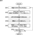
- the coding rate setting unit 611 sets the code length N and coding rate of the LDPC code in accordance with, for example, an operator's operation.
- the parity check matrix generation unit 613 uses the parity check matrix initial value table read from the storage unit 602 by the initial value table reading unit 612, and the code length N and the coding rate determined by the coding rate setting unit 611.
- the parity check matrix H of the LDPC code of r is obtained (generated), supplied to the storage unit 602 and stored.
- step S206 If it is determined in step S206 that the LDPC encoding is to be ended, that is, for example, if there is no LDPC target data to be LDPC encoded, the LDPC encoder 115 ends the processing.
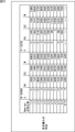
- FIG. 37 is a diagram illustrating an example of a parity check matrix initial value table.
- FIG. 37 shows that the code length N is 16200 bits and the coding rate (coding rate in the notation of DVB-T.2) r is 1/4 as defined in the DVB-T.2 standard.
- the parity check matrix initial value table with respect to the parity check matrix H is shown.
- the parity check matrix generator 613 obtains the parity check matrix H using the parity check matrix initial value table as follows.
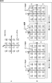
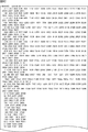
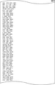
- FIG. 38 shows a method for obtaining the parity check matrix H from the parity check matrix initial value table.
- the parity check matrix initial value table indicates the position of one element of the information matrix H A (FIG. 10) corresponding to the information length K corresponding to the code length N of the LDPC code and the coding rate r, as 360 columns.
- This is a table expressed for each (number of columns P of the unit of the cyclic structure), and in the i-th row, the row number of the 1 element of the 1 + 360 ⁇ (i ⁇ 1) -th column of the check matrix H (check matrix H (The row number where the row number of the first row is 0) is arranged by the number of column weights of the 1 + 360 ⁇ (i ⁇ 1) th column.
- parity matrix H T (FIG. 10) corresponding to parity length M of parity check matrix H is determined as shown in FIG. 25, according to parity check matrix initial value table, An information matrix H A (FIG. 10) corresponding to the information length K is obtained.
- the number of rows k + 1 in the parity check matrix initial value table differs depending on the information length K.
- 360 in Expression (9) is the number of columns P of the unit of the cyclic structure described in FIG.
- the first row of the parity check matrix initial value table of FIG. 38 is 0,2084,1613,1548,1286,1460,3196,4297,2481,3369,3451,4620,2622, which is the parity check matrix H
- the row number is 0,2084,1613,1548,1286,1460,3196,4297,2481,3369,3451,4620,2622
- the element of the row is 1 (and other elements) Is 0).
- the second row of the parity check matrix initial value table in FIG. 38 is 1,122,1516,3448,2880,1407,1847,3799,3529,373,971,4358,3108, which is 361 of the parity check matrix H.
- the row number is 1,122,1516,3448,2880,1407,1847,3799,3529,373,971,4358,3108, indicating that the element is 1 ing.
- the parity check matrix initial value table represents the position of one element of the information matrix HA of the parity check matrix H for every 360 columns.
- the numerical value of the i-th row (i-th from the top) and j-th column (j-th from the left) of the parity check matrix initial value table is represented as h i, j and j items in the w-th column of the parity check matrix H. If the row number of the first element is represented as H wj , the row number H of the first element in the w column, which is a column other than the 1 + 360 ⁇ (i ⁇ 1) column of the parity check matrix H wj can be obtained by Expression (10).
- mod (x, y) means the remainder of dividing x by y.
- P is the number of columns of the cyclic structure unit described above, and is 360, for example, in the DVB-S.2, DVB-T.2, and DVB-C.2 standards, as described above.
- the parity check matrix generation unit 613 (FIG. 35) specifies the row number of the 1 element in the 1 + 360 ⁇ (i ⁇ 1) column of the parity check matrix H by using the parity check matrix initial value table.
- the parity check matrix generation unit 613 calculates the row number H wj of the first element of the w column that is a column other than the 1 + 360 ⁇ (i ⁇ 1) column of the parity check matrix H by the formula ( 10) to generate a parity check matrix H in which the element of the row number obtained as described above is 1.
- DVB-Sx DVB-S.2
- the second requirement is to prepare 22 ModCods in the 12 dB range from 12 dB to 24 dB
- the third requirement is C / N from -3 dB to 5 dB. It is required to prepare 12 ModCods in the 8 dB range, and as a fourth requirement, to prepare 5 ModCods in the 7 dB range where C / N is from -10 dB to -3 dB. Yes.
- the ModCod FER Fra Error Rate
- the priority of the first request is the highest “1”, but the priority of the second to fourth requests is “2” which is lower than the priority of the first request. It has become.
- an LDPC code (a check matrix) that can satisfy the first requirement having the highest priority at least in CfT is provided as a new LDPC code.
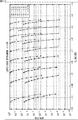
- FIG. 39 shows a BER / FER curve when QPSK is adopted as a modulation method for 11 LDPC codes with a code length N of 64k bits defined in DVB-S.2. .
- the horizontal axis represents E s / N 0 (signal power to noise power ratio per symbol) corresponding to C / N, and the vertical axis represents FER / BER.
- the solid line represents FER and the dotted line represents BER (Bit Error Rate).
- QPSK is adopted as a modulation method for 11 coding rate LDPC codes with a code length N of 64k bits as defined in DVB-S.2 in a range where E s / N 0 is 10 dB. There is a FER (BER) curve.
- the average interval of the FER curves between ModCod (hereinafter also referred to as the average interval) Is about 1 dB ( ⁇ 10 dB / (10-1)).
- the LDPC code with 11 coding rates can obtain ModCod with an average interval of about 1 dB compared to the case of DVB-S.2.
- the number is about three times the coding rate of 11 ( ⁇ 1 dB / 0.3 dB), that is, 30
- An LDPC code with a coding rate of about a level is sufficient.
- this technology is an LDPC code having a coding rate that is easy to set a coding rate of about 30.
- the coding rate is i / 30 (i is a positive integer less than 30) and the code length is 64k.
- the parity matrix of the parity check matrix H is the same as the LDPC code defined in DVB-S.2.
- H T is a stepped structure (FIG. 11).
- the information matrix HA of the check matrix H has a cyclic structure, and the number of columns P of the cyclic structure unit is also 360. To do.
- 40 to 106 are diagrams illustrating examples of the parity check matrix initial value table of the new LDPC code having the code length N of 64k bits and the encoding rate of i / 30 as described above.
- the new LDPC code is an LDPC code whose coding rate is represented by i / 30, the maximum is 1/30, 2/30, 3/30,..., 28/30, and There are 29 coding rate LDPC codes of 29/30.
- LDPC codes with a coding rate of 1/30 may be restricted in terms of efficiency.
- the use of LDPC codes with a coding rate of 29/30 may be restricted in terms of error rate (BER / FER).
- the LDPC code with a coding rate of 1/30 and the LDPC code with a coding rate of 29/30 may not be treated as a new LDPC code.
- LDPC codes with the coding rates 2/30 to 29/30 are referred to as new LDPC codes.
- the parity check matrix initial value table for the parity check matrix H of the LDPC code is shown.
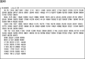
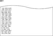
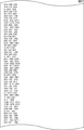
- FIG. 40 shows a parity check matrix initial value table for a parity check matrix H of an LDPC code having a code length N of 64k bits and a code rate r of 2/30.
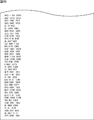
- FIG. 41 shows a parity check matrix initial value table for a parity check matrix H of an LDPC code having a code length N of 64k bits and an encoding rate r of 3/30.
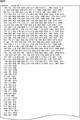
- FIG. 42 shows a parity check matrix initial value table for a parity check matrix H of an LDPC code having a code length N of 64k bits and a code rate r of 4/30.
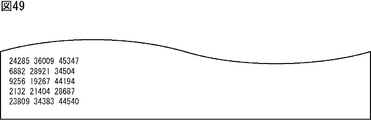
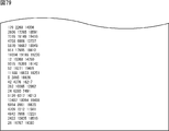
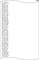
- 43 shows a parity check matrix initial value table for a parity check matrix H of an LDPC code having a code length N of 64k bits and a code rate r of 5/30.
- FIG. 45 shows a parity check matrix initial value table for a parity check matrix H of an LDPC code having a code length N of 64k bits and a coding rate r of 7/30.
- 46 and 47 show a parity check matrix initial value table for a parity check matrix H of an LDPC code having a code length N of 64k bits and a code rate r of 8/30.
- 50 and 51 show a parity check matrix initial value table for a parity check matrix H of an LDPC code having a code length N of 64k bits and a code rate r of 10/30.
- 52 and 53 show a parity check matrix initial value table for a parity check matrix H of an LDPC code having a code length N of 64k bits and a code rate r of 11/30.
- 54 and 55 illustrate a parity check matrix initial value table for a parity check matrix H of an LDPC code having a code length N of 64k bits and a code rate r of 12/30.
- 58 and 59 show a parity check matrix initial value table for a parity check matrix H of an LDPC code having a code length N of 64k bits and a code rate r of 14/30.
- 60 and 61 illustrate a parity check matrix initial value table for a parity check matrix H of an LDPC code having a code length N of 64k bits and a code rate r of 15/30.
- 62, 63, and 64 illustrate a parity check matrix initial value table for a parity check matrix H of an LDPC code having a code length N of 64k bits and a code rate r of 16/30.
- 65, 66, and 67 illustrate a parity check matrix initial value table for a parity check matrix H of an LDPC code having a code length N of 64k bits and a code rate r of 17/30.
- 68, 69, and 70 illustrate a parity check matrix initial value table for a parity check matrix H of an LDPC code having a code length N of 64k bits and a code rate r of 18/30.
- 71, 72, and 73 illustrate a parity check matrix initial value table for a parity check matrix H of an LDPC code having a code length N of 64k bits and a code rate r of 19/30.
- 74, 75, and 76 illustrate a parity check matrix initial value table for a parity check matrix H of an LDPC code having a code length N of 64k bits and a code rate r of 20/30.
- 77, 78, and 79 illustrate a parity check matrix initial value table for a parity check matrix H of an LDPC code having a code length N of 64k bits and a code rate r of 21/30.
- 80, 81, and 82 illustrate a parity check matrix initial value table for a parity check matrix H of an LDPC code having a code length N of 64k bits and a code rate r of 22/30.
- 83, 84, and 85 illustrate a parity check matrix initial value table for a parity check matrix H of an LDPC code having a code length N of 64k bits and a code rate r of 23/30.
- 86, 87, and 88 show a parity check matrix initial value table for a parity check matrix H of an LDPC code having a code length N of 64k bits and a code rate r of 24/30.
- 89, 90, and 91 illustrate a parity check matrix initial value table for a parity check matrix H of an LDPC code having a code length N of 64k bits and a code rate r of 25/30.
- 92, 93, and 94 show a parity check matrix initial value table for a parity check matrix H of an LDPC code having a code length N of 64k bits and a code rate r of 26/30.
- 95, 96, 97, and 98 show a parity check matrix initial value table for a parity check matrix H of an LDPC code having a code length N of 64k bits and a code rate r of 27/30.
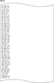
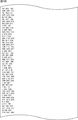
- 99, 100, 101, and 102 show a parity check matrix initial value table for a parity check matrix H of an LDPC code having a code length N of 64k bits and a code rate r of 28/30.
- 103, 104, 105, and 106 show a parity check matrix initial value table for a parity check matrix H of an LDPC code having a code length N of 64k bits and a coding rate r of 29/30.
- the LDPC encoder 115 uses the parity check matrix H obtained from the parity check matrix initial value tables shown in FIGS. 40 to 106, and has a code length N of 64k bits and an encoding rate r of 2 /. Coding into any (new) LDPC code of 28 types from 30 to 29/30 can be performed.
- the parity check matrix initial value table shown in FIGS. 40 to 106 is stored in the storage unit 602 of the LDPC encoder 115 (FIG. 8).
- all 28 types of LDPC codes with coding rates r of 2/30 to 29/30 need not necessarily be adopted as new LDPCs. Absent. That is, for the 28 types of LDPC codes with coding rates r of 2/30 to 29/30 in FIGS. 40 to 106, LDPC codes with any one or more coding rates are used as new LDPC codes. Can be adopted.
- the LDPC code obtained by using the parity check matrix H obtained from the parity check matrix initial value table in FIG. 40 to FIG. 106 is a high-performance LDPC code.
- a high-performance LDPC code is an LDPC code obtained from an appropriate check matrix H.
- the appropriate check matrix H is that when an LDPC code obtained from the check matrix H is transmitted at a low E s / N 0 or E b / N o (signal power to noise power ratio per bit).
- BER (and FER) is a check matrix that satisfies a predetermined condition.
- An appropriate parity check matrix H can be obtained, for example, by performing a simulation for measuring the BER when LDPC codes obtained from various parity check matrices satisfying a predetermined condition are transmitted at low E s / N o .
- the predetermined conditions that the appropriate check matrix H should satisfy are, for example, that the analysis result obtained by the code performance analysis method called “Density Evolution” is good, There are no loops, etc.
- the predetermined condition to be satisfied by the appropriate parity check matrix H can be determined as appropriate from the viewpoints of improving the decoding performance of the LDPC code, facilitating (simplifying) the decoding process of the LDPC code, and the like.
- FIG. 107 and FIG. 108 are diagrams for explaining density evolution in which an analysis result is obtained as a predetermined condition to be satisfied by an appropriate check matrix H.
- Density evolution is a code analysis method that calculates the expected value of the error probability for the entire LDPC code (ensemble) with a code length N of ⁇ characterized by a degree sequence described later. It is.
- the noise variance when the noise variance is increased from 0, the expected value of the error probability of a certain ensemble is initially 0, but the noise variance is greater than a certain threshold. Then, it is not 0.
- the expected value of the error probability is not zero, and the threshold of noise variance (hereinafter also referred to as performance threshold) is compared to determine whether the ensemble performance (appropriateness of the check matrix) is good or bad. Can be decided.
- performance threshold the threshold of noise variance
- a high-performance LDPC code can be found among the LDPC codes belonging to the ensemble.
- the above-described degree sequence represents the ratio of variable nodes and check nodes having weights of each value to the code length N of the LDPC code.
- a regular (3,6) LDPC code with a coding rate of 1/2 is a degree in which the weights (column weights) of all variable nodes are 3 and the weights (row weights) of all check nodes are 6. Belongs to an ensemble characterized by a sequence.
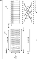
- FIG. 107 shows a Tanner graph of such an ensemble.
- Each variable node is connected with three edges equal to the column weight, and therefore there are only 3N branches connected to the N variable nodes.
- each check node is connected with 6 branches equal to the row weight, and therefore there are only 3N branches connected to N / 2 check nodes.
- the interleaver randomly reorders 3N branches connected to N variable nodes, and reorders each of the rearranged branches into 3N branches connected to N / 2 check nodes. Connect to one of them.
- the interleaver through which the branch connected to the variable node and the branch connected to the check node pass is divided into multiple (multi edge), which makes it possible to further characterize the ensemble. Strictly done.
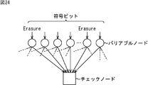
- FIG. 108 shows an example of a Tanner graph of a multi-edge type ensemble.
- Tanner graph of FIG. 108 there is one branch connected to the first interleaver, 0 branches connected to the second interleaver, only v1 variable, and one branch connected to the first interleaver.
- the Tanner graph of FIG. 108 there are two branches connected to the first interleaver, c1 check nodes with 0 branches connected to the second interleaver, and two branches connected to the first interleaver.
- the number of branches connected to the second interleaver is c2 check nodes, the number of branches connected to the first interleaver is 0, and the number of branches connected to the second interleaver is c3.
- Exists there are two branches connected to the first interleaver, c1 check nodes with 0 branches connected to the second interleaver, and two branches connected to the first interleaver.
- the BER starts to decrease (becomes smaller) due to multi-edge type density evolution E b / N 0 (Signal power to noise power ratio per bit) LDPC code that finds an ensemble whose performance threshold is less than or equal to a predetermined value and reduces the BER in multiple modulation schemes used in DVB-S.2 etc., such as QPSK, among the LDPC codes belonging to that ensemble was selected as a high-performance LDPC code.
- E b / N 0 Signal to noise power ratio per bit
- the above-mentioned parity check matrix initial value table of the new LDPC code is a parity check matrix initial value table of an LDPC code having a code length N of 64k bits, which is obtained by the above simulation.
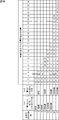
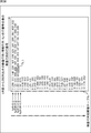
- FIG. 109 is a parity check matrix H obtained from the parity check matrix initial value table of 28 new LDPC codes with code length N of 64k bits and code rates of 2/30 to 29/30 in FIGS. It is a figure which shows the minimum cycle length and performance threshold value.
- the minimum cycle length (girth) means the minimum value of the loop length (loop length) composed of 1 elements in the check matrix H.
- Cycle 4 (a loop of one element with a loop length of 4) does not exist in the parity check matrix H obtained from the parity check matrix initial value table of the new LDPC code.
- the performance threshold tends to improve (decrease) as the encoding rate r decreases.
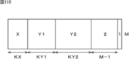
- FIG. 110 is a diagram for explaining a parity check matrix H (which is also referred to as a parity check matrix H of a new LDPC code) (shown from the parity check matrix initial value table) in FIGS. 40 to 106.
- a parity check matrix H which is also referred to as a parity check matrix H of a new LDPC code
- the column weight is X
- the subsequent KY1 column is the column weight Y1
- the subsequent KY2 column is the column weight Y2.
- the subsequent column M-1 has a column weight of 2
- the last column has a column weight of 1.
- the column weight on the head side (left side) tends to be larger as in the case of the parity check matrix described in FIG. 12 and FIG.
- the first code bit of the new LDPC code tends to be more resistant to errors (resistant to errors).
- the coding rate is 2/30, 3/30, 4/30, 5/30, 6/30, 7/30, 8/30, 9/30, 10/30, 11/30, 12/30, 13/30, 14/30, 15/30, 16/30, 17/30, 18/30, 19/30, 20/30, 21/30, 22/30, 23/30, 24/30, 25 /
- the shift amounts for the 30, 26/30, 27/30, 28/30, 29/30 new LDPC codes are 168, 162, 156, 150, 144, 138, 132, 126, 120, 114, 108, 102, 96, 90, 84, 78, 72, 66, 60, 54, 48, 42, respectively. 36,30,24,18,12,6.
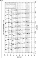
- the horizontal axis represents E s / N 0 and the vertical axis represents BER / FER.
- the solid line represents BER and the dotted line represents FER.
- the FER (BER) curve of the new LDPC code is relatively smaller for each of the low, medium, and high coding rate groups at intervals smaller than 1 dB. They are lined up at intervals. Therefore, for a broadcaster who broadcasts a program using the transmission device 11, the new LDPC code has an advantage that it is easy to select a coding rate used for broadcasting according to the channel (communication channel 13) status and the like.
- FIG. 115 is a diagram for explaining the BCH encoding used in the simulation.
- a in FIG. 115 is a diagram illustrating parameters of BCH encoding performed before LDPC encoding to a 64k LDPC code defined in DVB-S.2.
- the column twist deinterleaver 55 targets the LDPC code from the multiplexer 54, and corresponds to the column twist deinterleave as the rearrangement process performed by the column twist interleaver 24 in FIG. Processing), that is, column twist deinterleaving, for example, as reverse rearrangement processing for returning the code bits of LDPC codes whose rearrangement has been changed by column twist interleaving as rearrangement processing.
- the column twist deinterleaver 55 writes the code bit of the LDPC code to the memory for deinterleaving configured similarly to the memory 31 shown in FIG. Perform column twist deinterleaving.
- the bit deinterleaver 165 supports parity interleaving.
- Parity deinterleaving reverse processing of parity interleaving, that is, parity deinterleaving for returning the code bits of the LDPC code whose arrangement has been changed by parity interleaving
- reverse permutation processing corresponding to permutation processing
- column twist All of column twist deinterleaving corresponding to interleaving can be performed.
- 118 is a flowchart for explaining processing performed by the QAM decoder 164, the bit deinterleaver 165, and the LDPC decoder 166 of FIG.
- step S112 the bit deinterleaver 165 performs deinterleaving (bit deinterleaving) of the symbol bits of the symbols from the QAM decoder 164, and the process proceeds to step S113.
- step S112 in the bit deinterleaver 165, the multiplexer 54 performs a reverse permutation process on the symbol bits of the symbols from the QAM decoder 164, and converts the code bits of the LDPC code obtained as a result of This is supplied to the interleaver 55.
- the column twist deinterleaver 55 need not be provided in the bit deinterleaver 165 in FIG.
- the parity matrix has a staircase structure.
- s, t, x, and y are integers in the range of 0 ⁇ s ⁇ 5, 0 ⁇ t ⁇ 6, 0 ⁇ x ⁇ 5, 0 ⁇ t ⁇ 6, respectively. It is.
- a matrix obtained by performing row and column replacement on the parity check matrix H in FIG. 119 is the parity check matrix H ′ in FIG.
- the parity check matrix H ′ in FIG. 120 corresponds to the K + qx + y + 1-th column of the parity check matrix H in FIG. 119 (hereinafter referred to as the original parity check matrix as appropriate) as the K + Py + x + 1-th column.
- This is a conversion check matrix obtained by performing at least column replacement to be replaced with this column.
- these 5 ⁇ 5 matrices (unit matrix, quasi-unit matrix, shift matrix, sum matrix, 0 matrix) constituting the conversion check matrix H ′ are hereinafter appropriately referred to as constituent matrices.
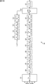
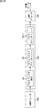
- FIG. 122 performs decoding of an LDPC code using at least the transformed parity check matrix H ′ of FIG. 121 obtained by performing column replacement of Expression (12) on the original parity check matrix H of FIG. 2 shows a configuration example of a decoding device.
- the shift check matrix H '(1,21) to (5,25) shift matrix (shift matrix obtained by cyclically shifting three 5 ⁇ 5 unit matrices to the right by 3)
- the data corresponding to the 1 position is stored.
- the third to eighth storage areas store data in association with the conversion parity check matrix H ′.
- 1 in the first row of the 5 ⁇ 5 unit matrix is replaced with 0 in the shift matrix from (1,86) to (5,90) of the conversion check matrix H ′. Data corresponding to one position of the shift matrix that has been shifted by one to the left.
- the constituent matrix is a P ⁇ P unit matrix having a weight of 1, a quasi-unit matrix in which one or more of the elements of the unit matrix are 0, or Data corresponding to the unit matrix, quasi-unit matrix, or 1 position of the shift matrix when the unit matrix or quasi-unit matrix is expressed in the form of a plurality of shift matrices obtained by cyclically shifting the unit matrix or quasi-unit matrix (Messages corresponding to branches belonging to the unit matrix, quasi-unit matrix, or shift matrix) are stored in the same address (the same FIFO among the FIFOs 300 1 to 300 6 ).
- the third to ninth storage areas are also stored in association with the conversion check matrix H ′.
- the branch data storage memory 304 is composed of 18 FIFOs 304 1 to 304 18 obtained by dividing the number of columns 90 of the conversion check matrix H ′ by 5 which is the number of columns of the constituent matrix (the number of columns P of the unit of the cyclic structure). Has been.
- FIFO304 The 1, data (messages u j from the check nodes) corresponding to the first position from the first row of the conversion parity check matrix H of FIG. 121 'to the fifth column, packed vertically in each column both Stored in the form (ignoring 0). That is, data corresponding to the position of 1 in the 5 ⁇ 5 unit matrix of (1, 1) to (5, 5) of the conversion parity check matrix H ′ is stored in the first-stage storage area of the FIFO 304 1 . .
- data is also stored in the storage areas of the fourth and fifth stages in association with the conversion parity check matrix H ′.
- the number of stages in the storage area of the FIFO 304 1 is 5, which is the maximum number of 1s (Hamming weights) in the row direction in the first to fifth columns of the conversion parity check matrix H ′.
- the branch data storage memory 300 includes six FIFOs 300 1 to 300 6 , and to which row of the conversion check matrix H ′ of FIG. 121 the five messages D 311 supplied from the preceding cyclic shift circuit 308 belong. according to the information (Matrix data) D312, a FIFO to store the data, select from among the FIFO300 1 to 300 6, will be stored in the order together five messages D311 to the selected FIFO. Also, the edge data storage memory 300, when reading data, sequentially reads five messages D300 1 from FIFO 300 1, supplied to the next stage of the selector 301. The branch data storage memory 300 reads the messages in order from the FIFOs 300 2 to 300 6 after reading the messages from the FIFO 300 1 and supplies them to the selector 301.
- Check node calculation section 302, 302 1 five check node calculator to consist 302 5, messages D302 (D302 1 to D302 5) supplied through the selector 301 using (messages v i of the expression (7)), A check node operation is performed according to Equation (7), and five messages D303 (D303 1 to D303 5 ) (message u j in Equation (7)) obtained as a result of the check node operation are supplied to the cyclic shift circuit 303.
- the cyclic shift circuit 303 circulates the five messages D303 1 to D303 5 obtained by the check node calculation unit 302 using unit matrices (or quasi-unit matrices) whose corresponding branches are the original in the conversion check matrix H ′.
- a cyclic shift is performed based on the information (Matrix data) D305 indicating whether the data has been click-shifted, and the result is supplied to the branch data storage memory 304 as a message D304.
- the selector 305 selects five messages from the FIFO from which the current data is read out of the FIFOs 304 1 to 304 18 in accordance with the select signal D307, and as the message D308, the variable node calculation unit 307 and the decoded word calculation unit 309.
- the variable node calculation unit 307 includes five variable node calculators 307 1 to 307 5 , a message D308 (D308 1 to D308 5 ) (message u j in Expression (1)) supplied through the selector 305, and received data. using five reception values supplied from use memory 306 D309 (formula (reception values u 0i 1)), the variable node operation according to equation (1), to the message D310 (D310 1 not obtained as a result of the calculation D310 5 ) (message v i in equation (1)) is supplied to the cyclic shift circuit 308.
- the cyclic shift circuit 308 cyclically shifts the message D310 1 to D310 5 calculated by the variable node calculation unit 307 by a number of unit matrices (or quasi-unit matrices) whose corresponding branches are the original in the transformation check matrix H ′. A cyclic shift is performed based on the information as to whether or not the data has been obtained, and the result is supplied to the branch data storage memory 300 as a message D311.
- the decoded word calculation unit 309 includes five decoded word calculators 309 1 to 309 5 , and five messages D308 (D308 1 to D308 5 ) (message u j in Expression (5)) output from the selector 305 and Using the five reception values D309 (the reception value u 0i in equation (5)) supplied from the reception data memory 306, the decoding result (decoding) based on equation (5) is used as the final stage of multiple times of decoding. And the decoded data D315 obtained as a result is supplied to the decoded data rearranging unit 311.
- the decoded data rearranging unit 311 rearranges the order of the decoded data D315 supplied from the decoded word calculation unit 309 by performing the column replacement in the formula (12), and obtains the final decoding result. Output as D316.
- the LDPC decoder 166 constituting the receiving device 12 performs LDPC decoding by simultaneously performing P check node operations and P variable node operations, for example, as in the decoding device of FIG.
- the column twist deinterleaver 55 performs the LDPC code on which the parity deinterleaving is not performed to the LDPC decoder 166, that is, the sequence of Expression (12).
- the LDPC code in a state where the replacement is performed is supplied, and the LDPC decoder 166 performs the same processing as that of the decoding device in FIG. 122 except that the column replacement of Expression (12) is not performed.
- FIG. 123 shows a configuration example of the LDPC decoder 166 of FIG.
- the scale can be reduced as compared with the decoding apparatus of FIG.
- the code length N of the LDPC code is 90
- the information length K is 60
- the number of columns of the unit of the cyclic structure (the number of rows and the number of columns of the constituent matrix).
- P is 5
- the LDPC code is a LDPC code in which the number P is 360 and the divisor q is M / P.
- the LDPC decoder 166 in FIG. 123 performs P check node operations and variable node operations for such LDPC codes. It is applicable when performing LDPC decoding by carrying out simultaneously.
- FIG. 124 is a diagram for explaining the processing of the multiplexer 54 constituting the bit deinterleaver 165 of FIG. 117.
- the multiplexer 54 includes a reverse switching unit 1001 and a memory 1002.
- the multiplexer 54 performs reverse replacement processing (reverse processing of replacement processing) corresponding to the replacement processing performed by the demultiplexer 25 of the transmission device 11 on the symbol bit of the symbol supplied from the preceding stage QAM decoder 164, that is, replacement.
- a reverse replacement process is performed to return the position of the code bit (symbol bit) of the LDPC code replaced by the process to the original position, and the resulting LDPC code is supplied to the subsequent column twist deinterleaver 55.
- the reverse switching unit 1001 includes the symbol bits y 0 , y 1 ,..., Y mb ⁇ 1 of the b symbols in units of (consecutive) b symbols. Is supplied.
- the reverse permutation unit 1001 replaces the mb symbol bits y 0 to y mb ⁇ 1 with the original mb bit code bits b 0 , b 1 ,. Reverse replacement is performed to return to the order of the sign bits b 0 to b mb ⁇ 1 before the replacement in the replacement unit 32 constituting the multiplexer 25, and the resulting mb bit code bits b 0 to b mb ⁇ 1 is output.
- the memory 1002 stores mb bits in the row (horizontal) direction and N / (mb in the column (vertical) direction, similarly to the memory 31 constituting the demultiplexer 25 on the transmission device 11 side. ) It has a storage capacity for storing bits. That is, the memory 1002 includes mb columns that store N / (mb) bits.
- the multiplexer 54 reads the code bits from the memory 1002 in the column direction and supplies them to the subsequent column twist deinterleaver 55.
- B in FIG. 124 is a diagram illustrating reading of the sign bit from the memory 1002.
- the multiplexer 54 reads the code bits of the LDPC code from the top to the bottom (column direction) of the columns constituting the memory 1002 from the left to the right columns.
- FIG. 125 is a diagram for explaining processing of the column twist deinterleaver 55 configuring the bit deinterleaver 165 of FIG. 117.
- FIG. 125 shows a configuration example of the memory 1002 of the multiplexer 54.
- the memory 1002 stores mb bits in the column (vertical) direction and has a storage capacity for storing N / (mb) bits in the row (horizontal) direction, and includes mb columns.
- the column twist deinterleaver 55 performs column twist deinterleaving by writing the code bit of the LDPC code in the row direction to the memory 1002 and controlling the read start position when reading in the column direction.
- the code bit sequence rearranged by the column twist interleave is appropriately changed by appropriately changing the read start position where the code bit read is started for each of the plurality of columns.
- a reverse rearrangement process for returning the sequence is performed.
- the column twist deinterleaver 55 sequentially writes the code bits of the LDPC code output from the reverse switching unit 1001 in the row direction, instead of the multiplexer 54, from the first row to the lower row of the memory 1002.
- the column twist deinterleaver 55 reads the code bits from the top to the bottom (column direction) from the top of the memory 1002 in the column from the left to the right. Do towards.
- the column twist deinterleaver 55 reads the code bit from the memory 1002 with the write start position where the column twist interleaver 24 on the transmission apparatus 11 side writes the code bit as the code bit read start position. .
- the modulation method is 16APSK or 16QAM
- multiple b Is 1 the column twist deinterleaver 55 sets the read start position for the leftmost column to the position where the address is 0, and (from the left) the read start position for the second column.
- the position is the position where the address is 2
- the read start position is the position of the address 4 for the third column
- the read start position is the position of the address 7 for the fourth column.
- FIG. 126 is a block diagram showing another configuration example of the bit deinterleaver 165 of FIG.
- bit deinterleaver 165 in FIG. 126 has the same configuration as that in FIG. 117 except that a parity deinterleaver 1011 is newly provided.
- the bit deinterleaver 165 includes a multiplexer (MUX) 54, a column twist deinterleaver 55, and a parity deinterleaver 1011.
- the bit deinterleaver 165 performs bit deinterleaving of the code bits of the LDPC code from the QAM decoder 164. Do.
- the multiplexer 54 replaces the LDPC code from the QAM decoder 164 by reverse replacement processing (reverse processing of the replacement processing) corresponding to the replacement processing performed by the demultiplexer 25 of the transmission device 11, that is, the replacement processing. Then, a reverse permutation process is performed to return the position of the code bit to the original position, and the resulting LDPC code is supplied to the column twist deinterleaver 55.
- reverse replacement processing reverse processing of the replacement processing
- the column twist deinterleaver 55 performs column twist deinterleave corresponding to the column twist interleave as the rearrangement process performed by the column twist interleaver 24 of the transmission device 11 for the LDPC code from the multiplexer 54.
- the LDPC code obtained as a result of the column twist deinterleave is supplied from the column twist deinterleaver 55 to the parity deinterleaver 1011.
- the parity deinterleaver 1011 targets the code bit after the column twist deinterleave in the column twist deinterleaver 55, and performs parity deinterleave corresponding to the parity interleave performed by the parity interleaver 23 of the transmission device 11 (inverse of parity interleave). In other words, parity deinterleaving is performed to return the code bits of the LDPC code whose arrangement has been changed by parity interleaving to the original order.
- the LDPC code obtained as a result of parity deinterleaving is supplied from the parity deinterleaver 1011 to the LDPC decoder 166.
- the LDPC decoder 166 includes the LDPC code subjected to the reverse permutation process, the column twist deinterleave, and the parity deinterleave, that is, the LDPC encoding according to the check matrix H.
- the LDPC code obtained by is supplied.
- the LDPC decoder 166 performs LDPC decoding of the LDPC code from the bit deinterleaver 165 using the parity check matrix H used by the LDPC encoder 115 of the transmission device 11 for LDPC encoding. That is, the LDPC decoder 166 performs LDPC decoding of the LDPC code from the bit deinterleaver 165 using the parity check matrix H itself used for the LDPC encoding by the LDPC encoder 115 of the transmission device 11 or to the parity check matrix H. On the other hand, the conversion check matrix obtained by performing at least column replacement corresponding to parity interleaving is used.
- the LDPC decoder 166 since the LDPC code obtained by the LDPC encoding according to the check matrix H is supplied from the bit deinterleaver 165 (its parity deinterleaver 1011) to the LDPC decoder 166, the LDPC When the LDPC decoding of the code is performed using the parity check matrix H itself used for the LDPC encoding by the LDPC encoder 115 of the transmission apparatus 11, the LDPC decoder 166, for example, a message (check node message, variable node message) Decoding device that performs LDPC decoding by full serial decoding (full serial decoding) method that sequentially performs operations of one node at a time, and full parallel decoding (full parallel) that performs message operations on all nodes simultaneously (in parallel) A decoding apparatus that performs LDPC decoding by a decoding method can be used.
- LDPC decoder 166 performs LDPC decoding of an LDPC code, and a transform check obtained by performing at least column replacement corresponding to parity interleaving on parity check matrix H used by LDPC encoder 115 of transmitting apparatus 11 for LDPC encoding
- the LDPC decoder 166 is an architecture decoding device that simultaneously performs P (or a divisor other than 1 of P) check node operations and variable node operations.
- the decoding apparatus (FIG. 122) having the received data rearrangement unit 310 that rearranges the code bits of the LDPC code by performing column replacement similar to the column replacement for obtaining the check matrix on the LDPC code. it can.
- a multiplexer 54 that performs reverse permutation processing, a column twist deinterleaver 55 that performs column twist deinterleaving, and a parity deinterleaver 1011 that performs parity deinterleaving are separately illustrated.
- the multiplexer 54, the column twist deinterleaver 55, and the parity deinterleaver 1011 are configured, the parity interleaver 23, the column twist interleaver 24, and the demultiplexer 25 of the transmission device 11 Similarly, it can be configured integrally.
- bit interleaver 116 (FIG. 8) of the transmission apparatus 11 is configured without the parity interleaver 23 and the column twist interleaver 24, the bit deinterleaver 165 in FIG. It is possible to configure without the twist deinterleaver 55 and the parity deinterleaver 1011.
- the LDPC decoder 166 includes a full serial decoding decoding apparatus that performs LDPC decoding using the check matrix H itself, a full parallel decoding decoding apparatus that performs LDPC decoding using the check matrix H itself,
- the transform parity check matrix H ′ can be used to configure the decoding apparatus (FIG. 122) having the received data rearrangement unit 310 that performs LDPC decoding by P simultaneous check node computations and variable node computations.
- FIG. 127 is a block diagram illustrating a first configuration example of a receiving system to which the receiving device 12 can be applied.
- the reception system includes an acquisition unit 1101, a transmission path decoding processing unit 1102, and an information source decoding processing unit 1103.
- the acquisition unit 1101 obtains a signal including an LDPC code obtained by LDPC encoding at least LDPC target data such as program image data and audio data, for example, terrestrial digital broadcasting, satellite digital broadcasting, CATV network, the Internet, and the like. Obtained via a transmission path (communication path) (not shown) such as a network of the network, and supplied to the transmission path decoding processing unit 1102.
- a transmission path communication path
- the acquisition unit 1101 when the signal acquired by the acquisition unit 1101 is broadcast from a broadcasting station via a terrestrial wave, a satellite wave, a CATV (Cable Television) network, or the like, the acquisition unit 1101 includes a tuner, It consists of STB (Set Top Box). Further, when the signal acquired by the acquisition unit 1101 is transmitted from a web server by multicast such as IPTV (Internet Protocol) Television, for example, the acquisition unit 1101 may be a NIC (Network Interface Card) or the like. Network I / F (Inter face).
- NIC Network Interface Card
- the transmission path decoding processing unit 1102 corresponds to the receiving device 12.
- the transmission path decoding processing unit 1102 performs a transmission path decoding process including at least processing for correcting an error occurring in the transmission path on the signal acquired by the acquisition unit 1101 via the transmission path, and obtains a signal obtained as a result thereof.
- the information is supplied to the information source decoding processing unit 1103.
- the signal acquired by the acquisition unit 1101 via the transmission path is a signal obtained by performing at least error correction coding for correcting an error occurring in the transmission path.
- the transmission path decoding processing unit 1102 Such a signal is subjected to transmission path decoding processing such as error correction processing, for example.
- examples of error correction coding include LDPC coding and BCH coding.
- at least LDPC encoding is performed as error correction encoding.
- the information source decoding processing unit 1103 performs an information source decoding process including at least a process of expanding the compressed information into the original information on the signal subjected to the transmission path decoding process.
- the signal acquired by the acquisition unit 1101 via the transmission path may be subjected to compression coding for compressing information in order to reduce the amount of data such as images and sounds as information.
- the information source decoding processing unit 1103 performs information source decoding processing such as processing (decompression processing) for expanding the compressed information to the original information on the signal subjected to the transmission path decoding processing.
- the information source decoding processing unit 1103 performs a process of expanding the compressed information to the original information. I will not.
- examples of the decompression process include MPEG decoding.
- the transmission path decoding process may include descrambling and the like in addition to the decompression process.
- the acquisition unit 1101 for example, compression coding such as MPEG coding is performed on data such as images and sound, and further error correction codes such as LDPC coding are performed.
- the processed signal is acquired via the transmission path and supplied to the transmission path decoding processing unit 1102.
- the transmission path decoding processing unit 1102 for example, processing similar to that performed by the receiving device 12 is performed on the signal from the acquisition unit 1101 as transmission path decoding processing, and the resulting signal is used as an information source. This is supplied to the decryption processing unit 1103.
- the information source decoding processing unit 1103 performs information source decoding processing such as MPEG decoding on the signal from the transmission path decoding processing unit 1102 and outputs the resulting image or sound.
- the reception system of FIG. 127 as described above can be applied to, for example, a television tuner that receives a television broadcast as a digital broadcast.
- the acquisition unit 1101, the transmission path decoding processing unit 1102, and the information source decoding processing unit 1103 are each configured as one independent device (hardware (IC (IntegratedIntegrCircuit) or the like) or software module)). It is possible.
- the set of the unit 1103, the acquisition unit 1101, the transmission path decoding processing unit 1102, and the information source decoding processing unit 1103 can be configured as one independent device.
- 128 is a block diagram illustrating a second configuration example of a receiving system to which the receiving device 12 can be applied.
- the reception system of FIG. 128 includes an acquisition unit 1101, a transmission path decoding processing unit 1102, and an information source decoding processing unit 1103, and is common to the case of FIG. 127, in that an output unit 1111 is newly provided. This is different from the case of FIG.
- the output unit 1111 is, for example, a display device that displays an image or a speaker that outputs audio, and outputs an image, audio, or the like as a signal output from the information source decoding processor 1103. That is, the output unit 1111 displays an image or outputs sound.
- the reception system of FIG. 128 as described above can be applied to, for example, a TV (television receiver) that receives a television broadcast as a digital broadcast, a radio receiver that receives a radio broadcast, or the like.
- a TV television receiver
- a radio receiver that receives a radio broadcast
- the signal output from the transmission path decoding processing unit 1102 is supplied to the output unit 1111.
- FIG. 129 is a block diagram illustrating a third configuration example of the receiving system to which the receiving device 12 can be applied.
- the reception system of FIG. 129 is common to the case of FIG. 127 in that it includes an acquisition unit 1101 and a transmission path decoding processing unit 1102.
- the receiving system of FIG. 129 is different from the case of FIG. 127 in that the information source decoding processing unit 1103 is not provided and the recording unit 1121 is newly provided.
- the recording unit 1121 records a signal (for example, TS packet of MPEG TS) output from the transmission path decoding processing unit 1102 on a recording (storage) medium such as an optical disk, a hard disk (magnetic disk), or a flash memory (memory). )
- a recording (storage) medium such as an optical disk, a hard disk (magnetic disk), or a flash memory (memory).
- the reception system of FIG. 129 as described above can be applied to a recorder or the like for recording a television broadcast.
- the receiving system is configured by providing an information source decoding processing unit 1103, and the information source decoding processing unit 1103 performs a signal after the information source decoding processing, that is, an image obtained by decoding, Audio can be recorded by the recording unit 1121.
- FIG. 130 shows a configuration example of an embodiment of a computer in which a program for executing the series of processes described above is installed.
- the program can be recorded in advance in a hard disk 705 or a ROM 703 as a recording medium built in the computer.
- the program is stored temporarily on a removable recording medium 711 such as a flexible disk, a CD-ROM (Compact Disc Read Only Memory), an MO (Magneto Optical) disc, a DVD (Digital Versatile Disc), a magnetic disc, or a semiconductor memory. It can be stored permanently (recorded).
- a removable recording medium 711 can be provided as so-called package software.
- the program is installed in the computer from the removable recording medium 711 as described above, or transferred from the download site to the computer wirelessly via a digital satellite broadcasting artificial satellite, LAN (Local Area Network),
- the program can be transferred to a computer via a network such as the Internet.
- the computer can receive the program transferred in this way by the communication unit 708 and install it in the built-in hard disk 705.
- the computer has a CPU (Central Processing Unit) 702 built-in.
- An input / output interface 710 is connected to the CPU 702 via a bus 701, and the CPU 702 operates an input unit 707 including a keyboard, a mouse, a microphone, and the like by the user via the input / output interface 710.
- a program stored in a ROM (Read Only Memory) 703 is executed accordingly.
- the CPU 702 may be a program stored in the hard disk 705, a program transferred from a satellite or a network, received by the communication unit 708 and installed in the hard disk 705, or a removable recording medium 711 installed in the drive 709.
- the program read and installed in the hard disk 705 is loaded into a RAM (Random Access Memory) 704 and executed.
- the CPU 702 performs processing according to the above-described flowchart or processing performed by the configuration of the above-described block diagram.
- the CPU 702 outputs the processing result from the output unit 706 configured by an LCD (Liquid Crystal Display), a speaker, or the like, for example, via the input / output interface 710 or from the communication unit 708 as necessary. Transmission and further recording on the hard disk 705 are performed.
- processing steps for describing a program for causing a computer to perform various types of processing do not necessarily have to be processed in time series according to the order described in the flowchart, but in parallel or individually. This includes processing to be executed (for example, parallel processing or processing by an object).
- the program may be processed by one computer, or may be processed in a distributed manner by a plurality of computers. Furthermore, the program may be transferred to a remote computer and executed.
- the above-described new LDPC code (the check matrix initial value table) is used regardless of whether the communication path 13 (FIG. 7) is a satellite line, a terrestrial wave, a cable (wired line), or the like. Is possible. Furthermore, the new LDPC code can be used for data transmission other than digital broadcasting.
Landscapes
- Physics & Mathematics (AREA)
- Engineering & Computer Science (AREA)
- Probability & Statistics with Applications (AREA)
- Theoretical Computer Science (AREA)
- Mathematical Physics (AREA)
- Computer Networks & Wireless Communication (AREA)
- Signal Processing (AREA)
- Mathematical Analysis (AREA)
- Mathematical Optimization (AREA)
- General Physics & Mathematics (AREA)
- Pure & Applied Mathematics (AREA)
- Computational Mathematics (AREA)
- Multimedia (AREA)
- Algebra (AREA)
- Computing Systems (AREA)
- Error Detection And Correction (AREA)
Abstract
Description

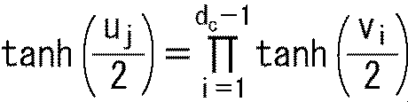
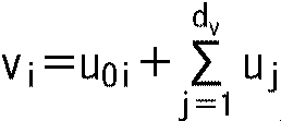
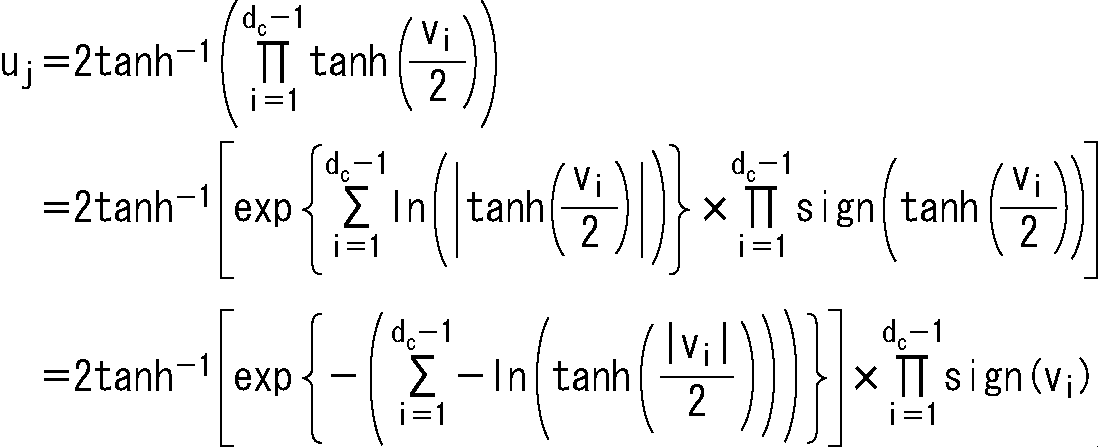
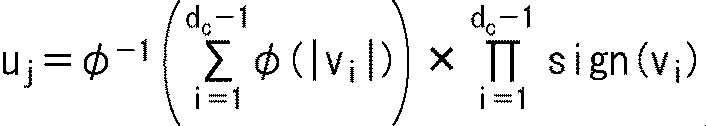
30 251 2458 3467 9897 12052 12191 15073 15949 16328 16972 17704 20672 22200 22276 25349 26106 28258 29737 30518 30951 32440 43031 46622 47113 52077 52609 52750 54295 55384 56954 57155 57853 59942
6985 7975 8681 10628 10866 13223 14882 18449 19570 24418 24538 24556 25926 26162 26947 28181 30049 33678 35497 37980 41276 43443 44124 48684 50382 51223 53635 57661 58040 59128 59300 59614 60200 60329
1896 5169 7347 10895 14434 14583 15125 15279 17169 18374 20805 25203 29509 30267 30925 33774 34653 34827 35707 36868 38136 38926 42690 43464 44624 46562 50291 50321 51544 56470 56532 58199 58398 60423
144 152 1236 8826 11983 12930 13349 19562 20564 30203 31766 35635 40367 40905 41792 41872 42428 43828 44359 47973 48041 49046 50158 50786 55527 55541 57260 57353 57821 58770 59098 59407 60358 60475
2085 28320 37838 50085
6903 21724 38880 59861
17156 20293 21231 44440
16799 38095 41049 44269
11939 30310 39689 47323
10563 17282 45331 60186
19860 23595 59085 60417
10403 19812 27225 48006
であるデータ処理装置又はデータ処理方法である。
153 2939 6037 11618 12401 17787 18472 22673 25220 26245 29839 35106 36915 37622 37655 45425 55595 56308 56726 58286
146 160 9060 12867 16536 20818 31754 35546 36480 36698 56314 56509 56837 57342 57373 57895 57947 58163 58202 58262
58 1555 10183 10446 12204 16197 16830 17382 19144 19565 21476 29121 41158 49953 51531 55642 57423 57587 57627 57974
120 9906 12466 21668 26856 27304 28451 29413 30168 31274 33309 33499 37486 38265 43457 50299 55218 56971 57059 58115
80 6649 9541 12490 14153 14346 19926 20677 23672 42397 45629 46288 55935 56115 56555 56865 56993 57921 58049 58190
46 152 3536 7134 9040 10474 10504 11549 17066 19102 27486 29364 39577 39995 48289 56236 57279 57560 57608 57930
19824 21165 34427 58143
22747 50215 50864 58176
2943 31340 39711 57281
1186 20802 27612 33409
1347 20868 29222 48776
19 8548 46255 56946
10762 20467 48519
39 7401 34355
142 10827 17009
1822 29424 39439
5944 11349 28870
4981 14731 15377
であるデータ処理装置又はデータ処理方法である。
7248 8578 11266 16015 17433 18038 20159 20848 22164 23848 24516 25093 25888 28382 31701 33259 33540 34615 36428 38595 38683 38814 41592 44323 44522 44859 45857 48657 49686 53354 54260 54853 55069 55426 56127
715 1505 3314 5537 6377 6750 11039 11271 15840 16615 24045 24314 24435 26992 28524 28745 28935 32956 33359 34964 36217 37546 38189 42599 44326 49694 54236 54779 55501 55543 55721 55865 55961 55966 55988
70 116 613 2482 6204 6608 7392 13585 14175 14228 17842 20004 20142 21324 22575 24443 24497 25394 26585 30222 37825 38548 41709 44999 50925 52186 53793 54177 54705 55096 55489 55584 56019 56055 56151
9 2054 3493 3584 3989 5916 11915 14323 15091 16998 17631 18645 18882 20510 27499 28990 30054 32231 36556 37437 39651 41543 41963 42798 42937 44864 48056 48971 53104 54511 54610 55151 55216 55470 55736
30 81 110 294 1636 2152 4312 6098 9415 12105 14021 15226 15618 18614 21368 23154 28913 29260 36969 37792 39386 42362 42949 43758 43765 44572 45877 46424 46948 47683 47903 48245 51804 52166 53264
3 50 987 1771 4255 9714 9907 13728 17807 20438 24206 24326 24458 26039 26898 35691 36875 37877 38103 38398 38671 39288 40642 41533 41753 42069 45374 46377 48016 48165 48805 49392 50660 51907 51968
138 441 4163 6450 7419 10743 11330 14962 14984 15032 24819 28987 29221 33223 35464 37535 38213 39085 39223 39925 41220 41341 41643 44944 46330 46870 47142 48577 49387 50732 52578 53839 54085 55426 56132
3773 41938 55428 55720
8833 47844 49437 50265
7054 31403 48642 53739
2286 22401 42270 53546
14435 24811 29047 36135
21010 23783 55073 55612
20516 27533 51132 52391
884 22844 25100 56123
1150 12133 44416 53752
9761 38585 52021 55545
1476 5057 49721 50744
16334 39503 40494 43840
24 31960 33866 53369
22065 22989 32356 52287
111 155 3706 13753
17878 18240 27828 55776
13582 47019 54558 55557
であるデータ処理装置又はデータ処理方法である。
2035 5424 6737 8778 10775 15496 17467 21825 23901 27869 28939 29614 34298 34951 35578 37326 39797 44488 45293 45900 49239 53415 53900
2090 4170 12643 12925 13383 17659 23995 24520 25766 26042 26585 29531 31126 34856 43610 49028 49872 50309 50455 51586 52161 52207 53263
819 1629 5521 8339 8501 18663 22208 24768 25082 35272 35560 40387 40618 42891 44288 46834 47264 47458 47561 48563 49141 49583 51837
100 564 4861 9130 15954 22395 23542 26105 27127 31905 33977 35256 37679 40472 40912 42224 43230 44945 45473 52217 52707 52953 53468
73 86 6004 9799 13581 14067 14910 14944 15502 22412 26032 27498 27746 27993 28590 35442 38766 44649 47956 48653 48724 50247 52165
108 1173 5321 6132 7304 15477 18466 19091 20238 23398 26431 34944 36899 40209 42997 48433 48762 49752 49826 50984 51319 53634 53657
4541 7635 11720 12065 16896 28028 28457 30950 35156 38740 39045 43153 43802 44180 45186 45716 45794 46645 48679 49071 49181 53212 53489
6118 8633 11204 11448 15114 19954 24570 26810 28236 39277 43584 46042 47499 48573 48715 49697 50511 51228 51563 51635 53410 53760 53851
1223 4008 8948 9130 16129 17767 22039 23572 24550 28200 29157 32730 33821 38449 39758 48433 49362 52582 53129 53282 53407 53414 53972
176 10948 11719 12340 13870 15842 18928 20987 24540 24852 28366 30017 36547 37426 38667 40361 44725 48275 48825 51211 52901 53737 53868
21792 35759 44481 53371
147 33771 34263 35853
15696 41236 46244 46674
48208 52868 53324 53794
34077 36441 49909 53506
34932 51666 53755 53974
18455 38927 49349 51201
3836 31114 37755 53469
31831 42633 46626 52743
21053 28415 46538 53154
5752 19363 42484
719 48444 52185
25502 53443 53739
11596 53495 53635
43934 52112 53323
42015 52196 52288
72 129 52340
9 17870 43153
24743 41406 53180
23388 48087 52441
であるデータ処理装置又はデータ処理方法である。
13033 14477 15028 17763 19244 20156 22458 24073 32202 32591 33531 33552 35823 41495 46351 49442 51612
44 66 8422 8760 14694 18768 20943 27806 29012 33594 36262 36820 40434 47704 49355 51729 51758
4233 16270 18958 20915 21313 27009 28249 33438 33855 34475 34541 37093 38835 42139 42169 44757 50122
82 10760 14292 17911 18008 23008 33152 34162 35749 36166 37411 37523 40838 42786 43581 46177 48829
4661 5201 5824 6014 8283 12840 22044 22103 29657 29722 32246 32893 34131 36007 40779 44900 51089
5869 12204 14095 26632 27101 27300 32344 33761 35081 38057 40709 46805 47733 48220 49806 51318 51691
87 5764 16204 20947 23257 31579 38832 40942 43112 43239 44602 49032 49482 49727 49929 50186 50593
880 1883 8876 9204 12370 21536 32858 35875 36247 36319 37151 38601 48914 49533 51239 51399 51824
20 129 2841 5695 8176 15720 26066 26197 34149 35814 36477 37478 45338 48988 50675 51071 51774
7252 14498 19246 20257 20693 22336 26037 29523 29844 34015 35828 38232 40999 41437 43343 44109 49883
4859 8000 9342 16137 21600 24083 36364 37038 38988 44465 45445 46569 48994 50591 51065 51166 51268
7728 9766 11199 11244 13877 14245 23083 27064 28433 28810 34979 39031 42939 44517 45730 48365 51374
67 135 1601 6123 9100 22043 24498 25417 30186 34430 34535 37216 40359 42794 47908 50685 51501
1006 10492 18259 51816
27272 49144 51574 51631
23 5636 38161 39514
9490 41564 46463 51162
33623 41959 50610
11626 22027 50936
28345 39504 45097
46639 50046 50319
74 18582 27985
102 17060 43142
38765 49453 51242
6102 41272 51729
24686 33446 49011
19634 49837 50000
569 22448 25746
33986 50729 51301
9883 14876 29601
9142 29505 50604
22623 40979 51260
23109 33398 51819
163 50643 50984
47021 47381 50970
16215 20964 21588
であるデータ処理装置又はデータ処理方法である。
30 251 2458 3467 9897 12052 12191 15073 15949 16328 16972 17704 20672 22200 22276 25349 26106 28258 29737 30518 30951 32440 43031 46622 47113 52077 52609 52750 54295 55384 56954 57155 57853 59942
6985 7975 8681 10628 10866 13223 14882 18449 19570 24418 24538 24556 25926 26162 26947 28181 30049 33678 35497 37980 41276 43443 44124 48684 50382 51223 53635 57661 58040 59128 59300 59614 60200 60329
1896 5169 7347 10895 14434 14583 15125 15279 17169 18374 20805 25203 29509 30267 30925 33774 34653 34827 35707 36868 38136 38926 42690 43464 44624 46562 50291 50321 51544 56470 56532 58199 58398 60423
144 152 1236 8826 11983 12930 13349 19562 20564 30203 31766 35635 40367 40905 41792 41872 42428 43828 44359 47973 48041 49046 50158 50786 55527 55541 57260 57353 57821 58770 59098 59407 60358 60475
2085 28320 37838 50085
6903 21724 38880 59861
17156 20293 21231 44440
16799 38095 41049 44269
11939 30310 39689 47323
10563 17282 45331 60186
19860 23595 59085 60417
10403 19812 27225 48006
になっている。
153 2939 6037 11618 12401 17787 18472 22673 25220 26245 29839 35106 36915 37622 37655 45425 55595 56308 56726 58286
146 160 9060 12867 16536 20818 31754 35546 36480 36698 56314 56509 56837 57342 57373 57895 57947 58163 58202 58262
58 1555 10183 10446 12204 16197 16830 17382 19144 19565 21476 29121 41158 49953 51531 55642 57423 57587 57627 57974
120 9906 12466 21668 26856 27304 28451 29413 30168 31274 33309 33499 37486 38265 43457 50299 55218 56971 57059 58115
80 6649 9541 12490 14153 14346 19926 20677 23672 42397 45629 46288 55935 56115 56555 56865 56993 57921 58049 58190
46 152 3536 7134 9040 10474 10504 11549 17066 19102 27486 29364 39577 39995 48289 56236 57279 57560 57608 57930
19824 21165 34427 58143
22747 50215 50864 58176
2943 31340 39711 57281
1186 20802 27612 33409
1347 20868 29222 48776
19 8548 46255 56946
10762 20467 48519
39 7401 34355
142 10827 17009
1822 29424 39439
5944 11349 28870
4981 14731 15377
になっている。
7248 8578 11266 16015 17433 18038 20159 20848 22164 23848 24516 25093 25888 28382 31701 33259 33540 34615 36428 38595 38683 38814 41592 44323 44522 44859 45857 48657 49686 53354 54260 54853 55069 55426 56127
715 1505 3314 5537 6377 6750 11039 11271 15840 16615 24045 24314 24435 26992 28524 28745 28935 32956 33359 34964 36217 37546 38189 42599 44326 49694 54236 54779 55501 55543 55721 55865 55961 55966 55988
70 116 613 2482 6204 6608 7392 13585 14175 14228 17842 20004 20142 21324 22575 24443 24497 25394 26585 30222 37825 38548 41709 44999 50925 52186 53793 54177 54705 55096 55489 55584 56019 56055 56151
9 2054 3493 3584 3989 5916 11915 14323 15091 16998 17631 18645 18882 20510 27499 28990 30054 32231 36556 37437 39651 41543 41963 42798 42937 44864 48056 48971 53104 54511 54610 55151 55216 55470 55736
30 81 110 294 1636 2152 4312 6098 9415 12105 14021 15226 15618 18614 21368 23154 28913 29260 36969 37792 39386 42362 42949 43758 43765 44572 45877 46424 46948 47683 47903 48245 51804 52166 53264
3 50 987 1771 4255 9714 9907 13728 17807 20438 24206 24326 24458 26039 26898 35691 36875 37877 38103 38398 38671 39288 40642 41533 41753 42069 45374 46377 48016 48165 48805 49392 50660 51907 51968
138 441 4163 6450 7419 10743 11330 14962 14984 15032 24819 28987 29221 33223 35464 37535 38213 39085 39223 39925 41220 41341 41643 44944 46330 46870 47142 48577 49387 50732 52578 53839 54085 55426 56132
3773 41938 55428 55720
8833 47844 49437 50265
7054 31403 48642 53739
2286 22401 42270 53546
14435 24811 29047 36135
21010 23783 55073 55612
20516 27533 51132 52391
884 22844 25100 56123
1150 12133 44416 53752
9761 38585 52021 55545
1476 5057 49721 50744
16334 39503 40494 43840
24 31960 33866 53369
22065 22989 32356 52287
111 155 3706 13753
17878 18240 27828 55776
13582 47019 54558 55557
になっている。
2035 5424 6737 8778 10775 15496 17467 21825 23901 27869 28939 29614 34298 34951 35578 37326 39797 44488 45293 45900 49239 53415 53900
2090 4170 12643 12925 13383 17659 23995 24520 25766 26042 26585 29531 31126 34856 43610 49028 49872 50309 50455 51586 52161 52207 53263
819 1629 5521 8339 8501 18663 22208 24768 25082 35272 35560 40387 40618 42891 44288 46834 47264 47458 47561 48563 49141 49583 51837
100 564 4861 9130 15954 22395 23542 26105 27127 31905 33977 35256 37679 40472 40912 42224 43230 44945 45473 52217 52707 52953 53468
73 86 6004 9799 13581 14067 14910 14944 15502 22412 26032 27498 27746 27993 28590 35442 38766 44649 47956 48653 48724 50247 52165
108 1173 5321 6132 7304 15477 18466 19091 20238 23398 26431 34944 36899 40209 42997 48433 48762 49752 49826 50984 51319 53634 53657
4541 7635 11720 12065 16896 28028 28457 30950 35156 38740 39045 43153 43802 44180 45186 45716 45794 46645 48679 49071 49181 53212 53489
6118 8633 11204 11448 15114 19954 24570 26810 28236 39277 43584 46042 47499 48573 48715 49697 50511 51228 51563 51635 53410 53760 53851
1223 4008 8948 9130 16129 17767 22039 23572 24550 28200 29157 32730 33821 38449 39758 48433 49362 52582 53129 53282 53407 53414 53972
176 10948 11719 12340 13870 15842 18928 20987 24540 24852 28366 30017 36547 37426 38667 40361 44725 48275 48825 51211 52901 53737 53868
21792 35759 44481 53371
147 33771 34263 35853
15696 41236 46244 46674
48208 52868 53324 53794
34077 36441 49909 53506
34932 51666 53755 53974
18455 38927 49349 51201
3836 31114 37755 53469
31831 42633 46626 52743
21053 28415 46538 53154
5752 19363 42484
719 48444 52185
25502 53443 53739
11596 53495 53635
43934 52112 53323
42015 52196 52288
72 129 52340
9 17870 43153
24743 41406 53180
23388 48087 52441
になっている。
13033 14477 15028 17763 19244 20156 22458 24073 32202 32591 33531 33552 35823 41495 46351 49442 51612
44 66 8422 8760 14694 18768 20943 27806 29012 33594 36262 36820 40434 47704 49355 51729 51758
4233 16270 18958 20915 21313 27009 28249 33438 33855 34475 34541 37093 38835 42139 42169 44757 50122
82 10760 14292 17911 18008 23008 33152 34162 35749 36166 37411 37523 40838 42786 43581 46177 48829
4661 5201 5824 6014 8283 12840 22044 22103 29657 29722 32246 32893 34131 36007 40779 44900 51089
5869 12204 14095 26632 27101 27300 32344 33761 35081 38057 40709 46805 47733 48220 49806 51318 51691
87 5764 16204 20947 23257 31579 38832 40942 43112 43239 44602 49032 49482 49727 49929 50186 50593
880 1883 8876 9204 12370 21536 32858 35875 36247 36319 37151 38601 48914 49533 51239 51399 51824
20 129 2841 5695 8176 15720 26066 26197 34149 35814 36477 37478 45338 48988 50675 51071 51774
7252 14498 19246 20257 20693 22336 26037 29523 29844 34015 35828 38232 40999 41437 43343 44109 49883
4859 8000 9342 16137 21600 24083 36364 37038 38988 44465 45445 46569 48994 50591 51065 51166 51268
7728 9766 11199 11244 13877 14245 23083 27064 28433 28810 34979 39031 42939 44517 45730 48365 51374
67 135 1601 6123 9100 22043 24498 25417 30186 34430 34535 37216 40359 42794 47908 50685 51501
1006 10492 18259 51816
27272 49144 51574 51631
23 5636 38161 39514
9490 41564 46463 51162
33623 41959 50610
11626 22027 50936
28345 39504 45097
46639 50046 50319
74 18582 27985
102 17060 43142
38765 49453 51242
6102 41272 51729
24686 33446 49011
19634 49837 50000
569 22448 25746
33986 50729 51301
9883 14876 29601
9142 29505 50604
22623 40979 51260
23109 33398 51819
163 50643 50984
47021 47381 50970
16215 20964 21588
になっている。
・・・(8)
・・・(9)
・・・(10)
・・・(11)
・・・(12)
Claims (54)
- LDPC(Low Density Parity Check)符号の検査行列に基づき、情報ビットを、符号長が64800ビットで符号化率が2/30のLDPC符号に符号化する符号化部を備え、
前記LDPC符号は、情報ビットとパリティビットを含み、
前記検査行列は、前記情報ビットに対応する情報行列部と前記パリティビットに対応するパリティ行列部とを含み、
前記情報行列部は、検査行列初期値テーブルによって表され、
前記検査行列初期値テーブルは、前記情報行列部の1の要素の位置を360列ごとに表すテーブルであって、
30 251 2458 3467 9897 12052 12191 15073 15949 16328 16972 17704 20672 22200 22276 25349 26106 28258 29737 30518 30951 32440 43031 46622 47113 52077 52609 52750 54295 55384 56954 57155 57853 59942
6985 7975 8681 10628 10866 13223 14882 18449 19570 24418 24538 24556 25926 26162 26947 28181 30049 33678 35497 37980 41276 43443 44124 48684 50382 51223 53635 57661 58040 59128 59300 59614 60200 60329
1896 5169 7347 10895 14434 14583 15125 15279 17169 18374 20805 25203 29509 30267 30925 33774 34653 34827 35707 36868 38136 38926 42690 43464 44624 46562 50291 50321 51544 56470 56532 58199 58398 60423
144 152 1236 8826 11983 12930 13349 19562 20564 30203 31766 35635 40367 40905 41792 41872 42428 43828 44359 47973 48041 49046 50158 50786 55527 55541 57260 57353 57821 58770 59098 59407 60358 60475
2085 28320 37838 50085
6903 21724 38880 59861
17156 20293 21231 44440
16799 38095 41049 44269
11939 30310 39689 47323
10563 17282 45331 60186
19860 23595 59085 60417
10403 19812 27225 48006
である
データ処理装置。 - 前記検査行列初期値テーブルの行をiと表すとともに、前記LDPC符号のパリティ長をMと表すとき、
前記検査行列の2+360×(i-1)列目は、前記検査行列初期値テーブルで1の要素の位置が表される前記検査行列の1+360×(i-1)列目を、q=M/360だけ下方向にサイクリックシフトした列である
請求項1に記載のデータ処理装置。 - 前記検査行列の1+360×(i-1)列については、
前記検査行列初期値テーブルのi行目が、前記検査行列の1+360×(i-1)列目の1の要素の行番号を表し、
前記検査行列の1+360×(i-1)列目以外の列である2+360×(i-1)列目から360×i列目までの各列については、
前記検査行列初期値テーブルのi行目のj列目の数値をhi,jと表すとともに、前記検査行列Hのw列目の、j個目の1の要素の行番号をHw-jと表すとき、
前記検査行列の1+360×(i-1)列目以外の列であるw列目の、1の要素の行番号Hw-jは、式Hw-j=mod{hi,j+mod((w-1),360)×M/360,M)で表される
請求項2に記載のデータ処理装置。 - 前記qは、168である
請求項2に記載のデータ処理装置。 - 前記LDPC符号の符号ビットのパリティビットのみをインターリーブするパリティインターリーブ部をさらに備える
請求項1に記載のデータ処理装置。 - 前記LDPC符号の符号ビットを、カラム方向にずらして記憶することによりカラムツイストインターリーブを行うカラムツイストインターリーブ部をさらに備える
請求項1に記載のデータ処理装置。 - 前記LDPC符号の符号ビットを、所定のディジタル変調方式で定める所定数の信号点のうちのいずれかに対応するシンボルのシンボルビットに入れ替える入れ替え部をさらに備える
請求項1に記載のデータ処理装置。 - 前記入れ替え部は、カラム方向に記憶されてロウ方向に読み出される前記符号ビットを入れ替える
請求項7に記載のデータ処理装置。 - 前記検査行列は、サイクル4が存在しない検査行列である
請求項1に記載のデータ処理装置。 - 前記検査行列は、マルチエッジタイプのデンシティエボリューションによって検出される、BERが落ち始めるEb/N0である性能閾値が所定値以下になるLDPC符号のアンサンブルに属するLDPC符号の検査行列である
請求項1に記載のデータ処理装置。 - LDPC(Low Density Parity Check)符号の検査行列に基づき、情報ビットを、符号長が64800ビットで符号化率が2/30のLDPC符号に符号化する符号化ステップを備え、
前記LDPC符号は、情報ビットとパリティビットを含み、
前記検査行列は、前記情報ビットに対応する情報行列部と前記パリティビットに対応するパリティ行列部とを含み、
前記情報行列部は、検査行列初期値テーブルによって表され、
前記検査行列初期値テーブルは、前記情報行列部の1の要素の位置を360列ごとに表すテーブルであって、
30 251 2458 3467 9897 12052 12191 15073 15949 16328 16972 17704 20672 22200 22276 25349 26106 28258 29737 30518 30951 32440 43031 46622 47113 52077 52609 52750 54295 55384 56954 57155 57853 59942
6985 7975 8681 10628 10866 13223 14882 18449 19570 24418 24538 24556 25926 26162 26947 28181 30049 33678 35497 37980 41276 43443 44124 48684 50382 51223 53635 57661 58040 59128 59300 59614 60200 60329
1896 5169 7347 10895 14434 14583 15125 15279 17169 18374 20805 25203 29509 30267 30925 33774 34653 34827 35707 36868 38136 38926 42690 43464 44624 46562 50291 50321 51544 56470 56532 58199 58398 60423
144 152 1236 8826 11983 12930 13349 19562 20564 30203 31766 35635 40367 40905 41792 41872 42428 43828 44359 47973 48041 49046 50158 50786 55527 55541 57260 57353 57821 58770 59098 59407 60358 60475
2085 28320 37838 50085
6903 21724 38880 59861
17156 20293 21231 44440
16799 38095 41049 44269
11939 30310 39689 47323
10563 17282 45331 60186
19860 23595 59085 60417
10403 19812 27225 48006
である
データ処理方法。 - 前記検査行列初期値テーブルの行をiと表すとともに、前記LDPC符号のパリティ長をMと表すとき、
前記検査行列の2+360×(i-1)列目は、前記検査行列初期値テーブルで1の要素の位置が表される前記検査行列の1+360×(i-1)列目を、q=M/360だけ下方向にサイクリックシフトした列である
請求項11に記載のデータ処理方法。 - 前記検査行列の1+360×(i-1)列については、
前記検査行列初期値テーブルのi行目が、前記検査行列の1+360×(i-1)列目の1の要素の行番号を表し、
前記検査行列の1+360×(i-1)列目以外の列である2+360×(i-1)列目から360×i列目までの各列については、
前記検査行列初期値テーブルのi行目のj列目の数値をhi,jと表すとともに、前記検査行列Hのw列目の、j個目の1の要素の行番号をHw-jと表すとき、
前記検査行列の1+360×(i-1)列目以外の列であるw列目の、1の要素の行番号Hw-jは、式Hw-j=mod{hi,j+mod((w-1),360)×M/360,M)で表される
請求項12に記載のデータ処理方法。 - 前記qは、168である
請求項12に記載のデータ処理方法。 - 前記LDPC符号の符号ビットのパリティビットのみをインターリーブする
請求項11に記載のデータ処理方法。 - 前記LDPC符号の符号ビットを、カラム方向にずらして記憶することによりカラムツイストインターリーブを行う
請求項11に記載のデータ処理方法。 - 前記LDPC符号の符号ビットを、所定のディジタル変調方式で定める所定数の信号点のうちのいずれかに対応するシンボルのシンボルビットに入れ替える
請求項11に記載のデータ処理方法。 - 前記符号ビットの入れ替えでは、カラム方向に記憶されてロウ方向に読み出される前記符号ビットを入れ替える
請求項17に記載のデータ処理方法。 - 前記検査行列は、サイクル4が存在しない検査行列である
請求項11に記載のデータ処理方法。 - 前記検査行列は、マルチエッジタイプのデンシティエボリューションによって検出される、BERが落ち始めるEb/N0である性能閾値が所定値以下になるLDPC符号のアンサンブルに属するLDPC符号の検査行列である
請求項11に記載のデータ処理方法。 - LDPC(Low Density Parity Check)符号の検査行列に基づき、符号長が64800ビットで符号化率が2/30のLDPC符号を復号する復号部を備え、
前記LDPC符号は、情報ビットとパリティビットを含み、
前記検査行列は、前記情報ビットに対応する情報行列部と前記パリティビットに対応するパリティ行列部とを含み、
前記情報行列部は、検査行列初期値テーブルによって表され、
前記検査行列初期値テーブルは、前記情報行列部の1の要素の位置を360列ごとに表すテーブルであって、
30 251 2458 3467 9897 12052 12191 15073 15949 16328 16972 17704 20672 22200 22276 25349 26106 28258 29737 30518 30951 32440 43031 46622 47113 52077 52609 52750 54295 55384 56954 57155 57853 59942
6985 7975 8681 10628 10866 13223 14882 18449 19570 24418 24538 24556 25926 26162 26947 28181 30049 33678 35497 37980 41276 43443 44124 48684 50382 51223 53635 57661 58040 59128 59300 59614 60200 60329
1896 5169 7347 10895 14434 14583 15125 15279 17169 18374 20805 25203 29509 30267 30925 33774 34653 34827 35707 36868 38136 38926 42690 43464 44624 46562 50291 50321 51544 56470 56532 58199 58398 60423
144 152 1236 8826 11983 12930 13349 19562 20564 30203 31766 35635 40367 40905 41792 41872 42428 43828 44359 47973 48041 49046 50158 50786 55527 55541 57260 57353 57821 58770 59098 59407 60358 60475
2085 28320 37838 50085
6903 21724 38880 59861
17156 20293 21231 44440
16799 38095 41049 44269
11939 30310 39689 47323
10563 17282 45331 60186
19860 23595 59085 60417
10403 19812 27225 48006
である
データ処理装置。 - 前記検査行列初期値テーブルの行をiと表すとともに、前記LDPC符号のパリティ長をMと表すとき、
前記検査行列の2+360×(i-1)列目は、前記検査行列初期値テーブルで1の要素の位置が表される前記検査行列の1+360×(i-1)列目を、q=M/360だけ下方向にサイクリックシフトした列である
請求項21に記載のデータ処理装置。 - 前記検査行列の1+360×(i-1)列については、
前記検査行列初期値テーブルのi行目が、前記検査行列の1+360×(i-1)列目の1の要素の行番号を表し、
前記検査行列の1+360×(i-1)列目以外の列である2+360×(i-1)列目から360×i列目までの各列については、
前記検査行列初期値テーブルのi行目のj列目の数値をhi,jと表すとともに、前記検査行列Hのw列目の、j個目の1の要素の行番号をHw-jと表すとき、
前記検査行列の1+360×(i-1)列目以外の列であるw列目の、1の要素の行番号Hw-jは、式Hw-j=mod{hi,j+mod((w-1),360)×M/360,M)で表される
請求項22に記載のデータ処理装置。 - 前記qは、168である
請求項22に記載のデータ処理装置。 - 前記LDPC符号の符号ビットを、カラム方向にずらして記憶することによりカラムツイストインターリーブが行われている場合に、前記LDPC符号の符号ビットを元の並びに戻すカラムツイストデインターリーブを行うカラムツイストデインターリーブ部をさらに備える
請求項21に記載のデータ処理装置。 - 前記LDPC符号の符号ビットを、所定のディジタル変調方式で定める所定数の信号点のうちのいずれかに対応するシンボルのシンボルビットに入れ替える入れ替え処理が行われている場合に、前記シンボルビットとして位置が入れ替えられた前記符号ビットを、元の位置に戻す逆入れ替え処理を行う逆入れ替え部をさらに備える
請求項21に記載のデータ処理装置。 - 前記逆入れ替え部は、ロウ方向に記憶されてカラム方向に読み出される前記符号ビットを元の位置に戻す逆入れ替え処理を行う
請求項26に記載のデータ処理装置。 - 前記検査行列は、サイクル4が存在しない検査行列である
請求項21に記載のデータ処理装置。 - 前記検査行列は、マルチエッジタイプのデンシティエボリューションによって検出される、BERが落ち始めるEb/N0である性能閾値が所定値以下になるLDPC符号のアンサンブルに属するLDPC符号の検査行列である
請求項21に記載のデータ処理装置。 - LDPC(Low Density Parity Check)符号の検査行列に基づき、符号長が64800ビットで符号化率が2/30のLDPC符号を復号する復号ステップを備え、
前記LDPC符号は、情報ビットとパリティビットを含み、
前記検査行列は、前記情報ビットに対応する情報行列部と前記パリティビットに対応するパリティ行列部とを含み、
前記情報行列部は、検査行列初期値テーブルによって表され、
前記検査行列初期値テーブルは、前記情報行列部の1の要素の位置を360列ごとに表すテーブルであって、
30 251 2458 3467 9897 12052 12191 15073 15949 16328 16972 17704 20672 22200 22276 25349 26106 28258 29737 30518 30951 32440 43031 46622 47113 52077 52609 52750 54295 55384 56954 57155 57853 59942
6985 7975 8681 10628 10866 13223 14882 18449 19570 24418 24538 24556 25926 26162 26947 28181 30049 33678 35497 37980 41276 43443 44124 48684 50382 51223 53635 57661 58040 59128 59300 59614 60200 60329
1896 5169 7347 10895 14434 14583 15125 15279 17169 18374 20805 25203 29509 30267 30925 33774 34653 34827 35707 36868 38136 38926 42690 43464 44624 46562 50291 50321 51544 56470 56532 58199 58398 60423
144 152 1236 8826 11983 12930 13349 19562 20564 30203 31766 35635 40367 40905 41792 41872 42428 43828 44359 47973 48041 49046 50158 50786 55527 55541 57260 57353 57821 58770 59098 59407 60358 60475
2085 28320 37838 50085
6903 21724 38880 59861
17156 20293 21231 44440
16799 38095 41049 44269
11939 30310 39689 47323
10563 17282 45331 60186
19860 23595 59085 60417
10403 19812 27225 48006
である
データ処理方法。 - 前記検査行列初期値テーブルの行をiと表すとともに、前記LDPC符号のパリティ長をMと表すとき、
前記検査行列の2+360×(i-1)列目は、前記検査行列初期値テーブルで1の要素の位置が表される前記検査行列の1+360×(i-1)列目を、q=M/360だけ下方向にサイクリックシフトした列である
請求項30に記載のデータ処理方法。 - 前記検査行列の1+360×(i-1)列については、
前記検査行列初期値テーブルのi行目が、前記検査行列の1+360×(i-1)列目の1の要素の行番号を表し、
前記検査行列の1+360×(i-1)列目以外の列である2+360×(i-1)列目から360×i列目までの各列については、
前記検査行列初期値テーブルのi行目のj列目の数値をhi,jと表すとともに、前記検査行列Hのw列目の、j個目の1の要素の行番号をHw-jと表すとき、
前記検査行列の1+360×(i-1)列目以外の列であるw列目の、1の要素の行番号Hw-jは、式Hw-j=mod{hi,j+mod((w-1),360)×M/360,M)で表される
請求項31に記載のデータ処理方法。 - 前記qは、168である
請求項31に記載のデータ処理方法。 - 前記LDPC符号の符号ビットを、カラム方向にずらして記憶することによりカラムツイストインターリーブが行われている場合に、前記LDPC符号の符号ビットを元の並びに戻すカラムツイストデインターリーブを行う
請求項30に記載のデータ処理方法。 - 前記LDPC符号の符号ビットを、所定のディジタル変調方式で定める所定数の信号点のうちのいずれかに対応するシンボルのシンボルビットに入れ替える入れ替え処理が行われている場合に、前記シンボルビットとして位置が入れ替えられた前記符号ビットを、元の位置に戻す逆入れ替え処理を行う
請求項30に記載のデータ処理方法。 - 前記逆入れ替え処理では、ロウ方向に記憶されてカラム方向に読み出される前記符号ビットを元の位置に戻す
請求項35に記載のデータ処理方法。 - 前記検査行列は、サイクル4が存在しない検査行列である
請求項30に記載のデータ処理方法。 - 前記検査行列は、マルチエッジタイプのデンシティエボリューションによって検出される、BERが落ち始めるEb/N0である性能閾値が所定値以下になるLDPC符号のアンサンブルに属するLDPC符号の検査行列である
請求項30に記載のデータ処理方法。 - LDPC(Low Density Parity Check)符号の検査行列に基づき、情報ビットを、符号長が64800ビットで符号化率が3/30のLDPC符号に符号化する符号化部を備え、
前記LDPC符号は、情報ビットとパリティビットを含み、
前記検査行列は、前記情報ビットに対応する情報行列部と前記パリティビットに対応するパリティ行列部とを含み、
前記情報行列部は、検査行列初期値テーブルによって表され、
前記検査行列初期値テーブルは、前記情報行列部の1の要素の位置を360列ごとに表すテーブルであって、
153 2939 6037 11618 12401 17787 18472 22673 25220 26245 29839 35106 36915 37622 37655 45425 55595 56308 56726 58286
146 160 9060 12867 16536 20818 31754 35546 36480 36698 56314 56509 56837 57342 57373 57895 57947 58163 58202 58262
58 1555 10183 10446 12204 16197 16830 17382 19144 19565 21476 29121 41158 49953 51531 55642 57423 57587 57627 57974
120 9906 12466 21668 26856 27304 28451 29413 30168 31274 33309 33499 37486 38265 43457 50299 55218 56971 57059 58115
80 6649 9541 12490 14153 14346 19926 20677 23672 42397 45629 46288 55935 56115 56555 56865 56993 57921 58049 58190
46 152 3536 7134 9040 10474 10504 11549 17066 19102 27486 29364 39577 39995 48289 56236 57279 57560 57608 57930
19824 21165 34427 58143
22747 50215 50864 58176
2943 31340 39711 57281
1186 20802 27612 33409
1347 20868 29222 48776
19 8548 46255 56946
10762 20467 48519
39 7401 34355
142 10827 17009
1822 29424 39439
5944 11349 28870
4981 14731 15377
である
データ処理装置。 - LDPC(Low Density Parity Check)符号の検査行列に基づき、情報ビットを、符号長が64800ビットで符号化率が3/30のLDPC符号に符号化する符号化ステップを備え、
前記LDPC符号は、情報ビットとパリティビットを含み、
前記検査行列は、前記情報ビットに対応する情報行列部と前記パリティビットに対応するパリティ行列部とを含み、
前記情報行列部は、検査行列初期値テーブルによって表され、
前記検査行列初期値テーブルは、前記情報行列部の1の要素の位置を360列ごとに表すテーブルであって、
153 2939 6037 11618 12401 17787 18472 22673 25220 26245 29839 35106 36915 37622 37655 45425 55595 56308 56726 58286
146 160 9060 12867 16536 20818 31754 35546 36480 36698 56314 56509 56837 57342 57373 57895 57947 58163 58202 58262
58 1555 10183 10446 12204 16197 16830 17382 19144 19565 21476 29121 41158 49953 51531 55642 57423 57587 57627 57974
120 9906 12466 21668 26856 27304 28451 29413 30168 31274 33309 33499 37486 38265 43457 50299 55218 56971 57059 58115
80 6649 9541 12490 14153 14346 19926 20677 23672 42397 45629 46288 55935 56115 56555 56865 56993 57921 58049 58190
46 152 3536 7134 9040 10474 10504 11549 17066 19102 27486 29364 39577 39995 48289 56236 57279 57560 57608 57930
19824 21165 34427 58143
22747 50215 50864 58176
2943 31340 39711 57281
1186 20802 27612 33409
1347 20868 29222 48776
19 8548 46255 56946
10762 20467 48519
39 7401 34355
142 10827 17009
1822 29424 39439
5944 11349 28870
4981 14731 15377
である
データ処理方法。 - LDPC(Low Density Parity Check)符号の検査行列に基づき、符号長が64800ビットで符号化率が3/30のLDPC符号を復号する復号部を備え、
前記LDPC符号は、情報ビットとパリティビットを含み、
前記検査行列は、前記情報ビットに対応する情報行列部と前記パリティビットに対応するパリティ行列部とを含み、
前記情報行列部は、検査行列初期値テーブルによって表され、
前記検査行列初期値テーブルは、前記情報行列部の1の要素の位置を360列ごとに表すテーブルであって、
153 2939 6037 11618 12401 17787 18472 22673 25220 26245 29839 35106 36915 37622 37655 45425 55595 56308 56726 58286
146 160 9060 12867 16536 20818 31754 35546 36480 36698 56314 56509 56837 57342 57373 57895 57947 58163 58202 58262
58 1555 10183 10446 12204 16197 16830 17382 19144 19565 21476 29121 41158 49953 51531 55642 57423 57587 57627 57974
120 9906 12466 21668 26856 27304 28451 29413 30168 31274 33309 33499 37486 38265 43457 50299 55218 56971 57059 58115
80 6649 9541 12490 14153 14346 19926 20677 23672 42397 45629 46288 55935 56115 56555 56865 56993 57921 58049 58190
46 152 3536 7134 9040 10474 10504 11549 17066 19102 27486 29364 39577 39995 48289 56236 57279 57560 57608 57930
19824 21165 34427 58143
22747 50215 50864 58176
2943 31340 39711 57281
1186 20802 27612 33409
1347 20868 29222 48776
19 8548 46255 56946
10762 20467 48519
39 7401 34355
142 10827 17009
1822 29424 39439
5944 11349 28870
4981 14731 15377
である
データ処理装置。 - LDPC(Low Density Parity Check)符号の検査行列に基づき、符号長が64800ビットで符号化率が3/30のLDPC符号を復号する復号ステップを備え、
前記LDPC符号は、情報ビットとパリティビットを含み、
前記検査行列は、前記情報ビットに対応する情報行列部と前記パリティビットに対応するパリティ行列部とを含み、
前記情報行列部は、検査行列初期値テーブルによって表され、
前記検査行列初期値テーブルは、前記情報行列部の1の要素の位置を360列ごとに表すテーブルであって、
153 2939 6037 11618 12401 17787 18472 22673 25220 26245 29839 35106 36915 37622 37655 45425 55595 56308 56726 58286
146 160 9060 12867 16536 20818 31754 35546 36480 36698 56314 56509 56837 57342 57373 57895 57947 58163 58202 58262
58 1555 10183 10446 12204 16197 16830 17382 19144 19565 21476 29121 41158 49953 51531 55642 57423 57587 57627 57974
120 9906 12466 21668 26856 27304 28451 29413 30168 31274 33309 33499 37486 38265 43457 50299 55218 56971 57059 58115
80 6649 9541 12490 14153 14346 19926 20677 23672 42397 45629 46288 55935 56115 56555 56865 56993 57921 58049 58190
46 152 3536 7134 9040 10474 10504 11549 17066 19102 27486 29364 39577 39995 48289 56236 57279 57560 57608 57930
19824 21165 34427 58143
22747 50215 50864 58176
2943 31340 39711 57281
1186 20802 27612 33409
1347 20868 29222 48776
19 8548 46255 56946
10762 20467 48519
39 7401 34355
142 10827 17009
1822 29424 39439
5944 11349 28870
4981 14731 15377
である
データ処理方法。 - LDPC(Low Density Parity Check)符号の検査行列に基づき、情報ビットを、符号長が64800ビットで符号化率が4/30のLDPC符号に符号化する符号化部を備え、
前記LDPC符号は、情報ビットとパリティビットを含み、
前記検査行列は、前記情報ビットに対応する情報行列部と前記パリティビットに対応するパリティ行列部とを含み、
前記情報行列部は、検査行列初期値テーブルによって表され、
前記検査行列初期値テーブルは、前記情報行列部の1の要素の位置を360列ごとに表すテーブルであって、
7248 8578 11266 16015 17433 18038 20159 20848 22164 23848 24516 25093 25888 28382 31701 33259 33540 34615 36428 38595 38683 38814 41592 44323 44522 44859 45857 48657 49686 53354 54260 54853 55069 55426 56127
715 1505 3314 5537 6377 6750 11039 11271 15840 16615 24045 24314 24435 26992 28524 28745 28935 32956 33359 34964 36217 37546 38189 42599 44326 49694 54236 54779 55501 55543 55721 55865 55961 55966 55988
70 116 613 2482 6204 6608 7392 13585 14175 14228 17842 20004 20142 21324 22575 24443 24497 25394 26585 30222 37825 38548 41709 44999 50925 52186 53793 54177 54705 55096 55489 55584 56019 56055 56151
9 2054 3493 3584 3989 5916 11915 14323 15091 16998 17631 18645 18882 20510 27499 28990 30054 32231 36556 37437 39651 41543 41963 42798 42937 44864 48056 48971 53104 54511 54610 55151 55216 55470 55736
30 81 110 294 1636 2152 4312 6098 9415 12105 14021 15226 15618 18614 21368 23154 28913 29260 36969 37792 39386 42362 42949 43758 43765 44572 45877 46424 46948 47683 47903 48245 51804 52166 53264
3 50 987 1771 4255 9714 9907 13728 17807 20438 24206 24326 24458 26039 26898 35691 36875 37877 38103 38398 38671 39288 40642 41533 41753 42069 45374 46377 48016 48165 48805 49392 50660 51907 51968
138 441 4163 6450 7419 10743 11330 14962 14984 15032 24819 28987 29221 33223 35464 37535 38213 39085 39223 39925 41220 41341 41643 44944 46330 46870 47142 48577 49387 50732 52578 53839 54085 55426 56132
3773 41938 55428 55720
8833 47844 49437 50265
7054 31403 48642 53739
2286 22401 42270 53546
14435 24811 29047 36135
21010 23783 55073 55612
20516 27533 51132 52391
884 22844 25100 56123
1150 12133 44416 53752
9761 38585 52021 55545
1476 5057 49721 50744
16334 39503 40494 43840
24 31960 33866 53369
22065 22989 32356 52287
111 155 3706 13753
17878 18240 27828 55776
13582 47019 54558 55557
である
データ処理装置。 - LDPC(Low Density Parity Check)符号の検査行列に基づき、情報ビットを、符号長が64800ビットで符号化率が4/30のLDPC符号に符号化する符号化ステップを備え、
前記LDPC符号は、情報ビットとパリティビットを含み、
前記検査行列は、前記情報ビットに対応する情報行列部と前記パリティビットに対応するパリティ行列部とを含み、
前記情報行列部は、検査行列初期値テーブルによって表され、
前記検査行列初期値テーブルは、前記情報行列部の1の要素の位置を360列ごとに表すテーブルであって、
7248 8578 11266 16015 17433 18038 20159 20848 22164 23848 24516 25093 25888 28382 31701 33259 33540 34615 36428 38595 38683 38814 41592 44323 44522 44859 45857 48657 49686 53354 54260 54853 55069 55426 56127
715 1505 3314 5537 6377 6750 11039 11271 15840 16615 24045 24314 24435 26992 28524 28745 28935 32956 33359 34964 36217 37546 38189 42599 44326 49694 54236 54779 55501 55543 55721 55865 55961 55966 55988
70 116 613 2482 6204 6608 7392 13585 14175 14228 17842 20004 20142 21324 22575 24443 24497 25394 26585 30222 37825 38548 41709 44999 50925 52186 53793 54177 54705 55096 55489 55584 56019 56055 56151
9 2054 3493 3584 3989 5916 11915 14323 15091 16998 17631 18645 18882 20510 27499 28990 30054 32231 36556 37437 39651 41543 41963 42798 42937 44864 48056 48971 53104 54511 54610 55151 55216 55470 55736
30 81 110 294 1636 2152 4312 6098 9415 12105 14021 15226 15618 18614 21368 23154 28913 29260 36969 37792 39386 42362 42949 43758 43765 44572 45877 46424 46948 47683 47903 48245 51804 52166 53264
3 50 987 1771 4255 9714 9907 13728 17807 20438 24206 24326 24458 26039 26898 35691 36875 37877 38103 38398 38671 39288 40642 41533 41753 42069 45374 46377 48016 48165 48805 49392 50660 51907 51968
138 441 4163 6450 7419 10743 11330 14962 14984 15032 24819 28987 29221 33223 35464 37535 38213 39085 39223 39925 41220 41341 41643 44944 46330 46870 47142 48577 49387 50732 52578 53839 54085 55426 56132
3773 41938 55428 55720
8833 47844 49437 50265
7054 31403 48642 53739
2286 22401 42270 53546
14435 24811 29047 36135
21010 23783 55073 55612
20516 27533 51132 52391
884 22844 25100 56123
1150 12133 44416 53752
9761 38585 52021 55545
1476 5057 49721 50744
16334 39503 40494 43840
24 31960 33866 53369
22065 22989 32356 52287
111 155 3706 13753
17878 18240 27828 55776
13582 47019 54558 55557
である
データ処理方法。 - LDPC(Low Density Parity Check)符号の検査行列に基づき、符号長が64800ビットで符号化率が4/30のLDPC符号を復号する復号部を備え、
前記LDPC符号は、情報ビットとパリティビットを含み、
前記検査行列は、前記情報ビットに対応する情報行列部と前記パリティビットに対応するパリティ行列部とを含み、
前記情報行列部は、検査行列初期値テーブルによって表され、
前記検査行列初期値テーブルは、前記情報行列部の1の要素の位置を360列ごとに表すテーブルであって、
7248 8578 11266 16015 17433 18038 20159 20848 22164 23848 24516 25093 25888 28382 31701 33259 33540 34615 36428 38595 38683 38814 41592 44323 44522 44859 45857 48657 49686 53354 54260 54853 55069 55426 56127
715 1505 3314 5537 6377 6750 11039 11271 15840 16615 24045 24314 24435 26992 28524 28745 28935 32956 33359 34964 36217 37546 38189 42599 44326 49694 54236 54779 55501 55543 55721 55865 55961 55966 55988
70 116 613 2482 6204 6608 7392 13585 14175 14228 17842 20004 20142 21324 22575 24443 24497 25394 26585 30222 37825 38548 41709 44999 50925 52186 53793 54177 54705 55096 55489 55584 56019 56055 56151
9 2054 3493 3584 3989 5916 11915 14323 15091 16998 17631 18645 18882 20510 27499 28990 30054 32231 36556 37437 39651 41543 41963 42798 42937 44864 48056 48971 53104 54511 54610 55151 55216 55470 55736
30 81 110 294 1636 2152 4312 6098 9415 12105 14021 15226 15618 18614 21368 23154 28913 29260 36969 37792 39386 42362 42949 43758 43765 44572 45877 46424 46948 47683 47903 48245 51804 52166 53264
3 50 987 1771 4255 9714 9907 13728 17807 20438 24206 24326 24458 26039 26898 35691 36875 37877 38103 38398 38671 39288 40642 41533 41753 42069 45374 46377 48016 48165 48805 49392 50660 51907 51968
138 441 4163 6450 7419 10743 11330 14962 14984 15032 24819 28987 29221 33223 35464 37535 38213 39085 39223 39925 41220 41341 41643 44944 46330 46870 47142 48577 49387 50732 52578 53839 54085 55426 56132
3773 41938 55428 55720
8833 47844 49437 50265
7054 31403 48642 53739
2286 22401 42270 53546
14435 24811 29047 36135
21010 23783 55073 55612
20516 27533 51132 52391
884 22844 25100 56123
1150 12133 44416 53752
9761 38585 52021 55545
1476 5057 49721 50744
16334 39503 40494 43840
24 31960 33866 53369
22065 22989 32356 52287
111 155 3706 13753
17878 18240 27828 55776
13582 47019 54558 55557
である
データ処理装置。 - LDPC(Low Density Parity Check)符号の検査行列に基づき、符号長が64800ビットで符号化率が4/30のLDPC符号を復号する復号ステップを備え、
前記LDPC符号は、情報ビットとパリティビットを含み、
前記検査行列は、前記情報ビットに対応する情報行列部と前記パリティビットに対応するパリティ行列部とを含み、
前記情報行列部は、検査行列初期値テーブルによって表され、
前記検査行列初期値テーブルは、前記情報行列部の1の要素の位置を360列ごとに表すテーブルであって、
7248 8578 11266 16015 17433 18038 20159 20848 22164 23848 24516 25093 25888 28382 31701 33259 33540 34615 36428 38595 38683 38814 41592 44323 44522 44859 45857 48657 49686 53354 54260 54853 55069 55426 56127
715 1505 3314 5537 6377 6750 11039 11271 15840 16615 24045 24314 24435 26992 28524 28745 28935 32956 33359 34964 36217 37546 38189 42599 44326 49694 54236 54779 55501 55543 55721 55865 55961 55966 55988
70 116 613 2482 6204 6608 7392 13585 14175 14228 17842 20004 20142 21324 22575 24443 24497 25394 26585 30222 37825 38548 41709 44999 50925 52186 53793 54177 54705 55096 55489 55584 56019 56055 56151
9 2054 3493 3584 3989 5916 11915 14323 15091 16998 17631 18645 18882 20510 27499 28990 30054 32231 36556 37437 39651 41543 41963 42798 42937 44864 48056 48971 53104 54511 54610 55151 55216 55470 55736
30 81 110 294 1636 2152 4312 6098 9415 12105 14021 15226 15618 18614 21368 23154 28913 29260 36969 37792 39386 42362 42949 43758 43765 44572 45877 46424 46948 47683 47903 48245 51804 52166 53264
3 50 987 1771 4255 9714 9907 13728 17807 20438 24206 24326 24458 26039 26898 35691 36875 37877 38103 38398 38671 39288 40642 41533 41753 42069 45374 46377 48016 48165 48805 49392 50660 51907 51968
138 441 4163 6450 7419 10743 11330 14962 14984 15032 24819 28987 29221 33223 35464 37535 38213 39085 39223 39925 41220 41341 41643 44944 46330 46870 47142 48577 49387 50732 52578 53839 54085 55426 56132
3773 41938 55428 55720
8833 47844 49437 50265
7054 31403 48642 53739
2286 22401 42270 53546
14435 24811 29047 36135
21010 23783 55073 55612
20516 27533 51132 52391
884 22844 25100 56123
1150 12133 44416 53752
9761 38585 52021 55545
1476 5057 49721 50744
16334 39503 40494 43840
24 31960 33866 53369
22065 22989 32356 52287
111 155 3706 13753
17878 18240 27828 55776
13582 47019 54558 55557
である
データ処理方法。 - LDPC(Low Density Parity Check)符号の検査行列に基づき、情報ビットを、符号長が64800ビットで符号化率が5/30のLDPC符号に符号化する符号化部を備え、
前記LDPC符号は、情報ビットとパリティビットを含み、
前記検査行列は、前記情報ビットに対応する情報行列部と前記パリティビットに対応するパリティ行列部とを含み、
前記情報行列部は、検査行列初期値テーブルによって表され、
前記検査行列初期値テーブルは、前記情報行列部の1の要素の位置を360列ごとに表すテーブルであって、
2035 5424 6737 8778 10775 15496 17467 21825 23901 27869 28939 29614 34298 34951 35578 37326 39797 44488 45293 45900 49239 53415 53900
2090 4170 12643 12925 13383 17659 23995 24520 25766 26042 26585 29531 31126 34856 43610 49028 49872 50309 50455 51586 52161 52207 53263
819 1629 5521 8339 8501 18663 22208 24768 25082 35272 35560 40387 40618 42891 44288 46834 47264 47458 47561 48563 49141 49583 51837
100 564 4861 9130 15954 22395 23542 26105 27127 31905 33977 35256 37679 40472 40912 42224 43230 44945 45473 52217 52707 52953 53468
73 86 6004 9799 13581 14067 14910 14944 15502 22412 26032 27498 27746 27993 28590 35442 38766 44649 47956 48653 48724 50247 52165
108 1173 5321 6132 7304 15477 18466 19091 20238 23398 26431 34944 36899 40209 42997 48433 48762 49752 49826 50984 51319 53634 53657
4541 7635 11720 12065 16896 28028 28457 30950 35156 38740 39045 43153 43802 44180 45186 45716 45794 46645 48679 49071 49181 53212 53489
6118 8633 11204 11448 15114 19954 24570 26810 28236 39277 43584 46042 47499 48573 48715 49697 50511 51228 51563 51635 53410 53760 53851
1223 4008 8948 9130 16129 17767 22039 23572 24550 28200 29157 32730 33821 38449 39758 48433 49362 52582 53129 53282 53407 53414 53972
176 10948 11719 12340 13870 15842 18928 20987 24540 24852 28366 30017 36547 37426 38667 40361 44725 48275 48825 51211 52901 53737 53868
21792 35759 44481 53371
147 33771 34263 35853
15696 41236 46244 46674
48208 52868 53324 53794
34077 36441 49909 53506
34932 51666 53755 53974
18455 38927 49349 51201
3836 31114 37755 53469
31831 42633 46626 52743
21053 28415 46538 53154
5752 19363 42484
719 48444 52185
25502 53443 53739
11596 53495 53635
43934 52112 53323
42015 52196 52288
72 129 52340
9 17870 43153
24743 41406 53180
23388 48087 52441
である
データ処理装置。 - LDPC(Low Density Parity Check)符号の検査行列に基づき、情報ビットを、符号長が64800ビットで符号化率が5/30のLDPC符号に符号化する符号化ステップを備え、
前記LDPC符号は、情報ビットとパリティビットを含み、
前記検査行列は、前記情報ビットに対応する情報行列部と前記パリティビットに対応するパリティ行列部とを含み、
前記情報行列部は、検査行列初期値テーブルによって表され、
前記検査行列初期値テーブルは、前記情報行列部の1の要素の位置を360列ごとに表すテーブルであって、
2035 5424 6737 8778 10775 15496 17467 21825 23901 27869 28939 29614 34298 34951 35578 37326 39797 44488 45293 45900 49239 53415 53900
2090 4170 12643 12925 13383 17659 23995 24520 25766 26042 26585 29531 31126 34856 43610 49028 49872 50309 50455 51586 52161 52207 53263
819 1629 5521 8339 8501 18663 22208 24768 25082 35272 35560 40387 40618 42891 44288 46834 47264 47458 47561 48563 49141 49583 51837
100 564 4861 9130 15954 22395 23542 26105 27127 31905 33977 35256 37679 40472 40912 42224 43230 44945 45473 52217 52707 52953 53468
73 86 6004 9799 13581 14067 14910 14944 15502 22412 26032 27498 27746 27993 28590 35442 38766 44649 47956 48653 48724 50247 52165
108 1173 5321 6132 7304 15477 18466 19091 20238 23398 26431 34944 36899 40209 42997 48433 48762 49752 49826 50984 51319 53634 53657
4541 7635 11720 12065 16896 28028 28457 30950 35156 38740 39045 43153 43802 44180 45186 45716 45794 46645 48679 49071 49181 53212 53489
6118 8633 11204 11448 15114 19954 24570 26810 28236 39277 43584 46042 47499 48573 48715 49697 50511 51228 51563 51635 53410 53760 53851
1223 4008 8948 9130 16129 17767 22039 23572 24550 28200 29157 32730 33821 38449 39758 48433 49362 52582 53129 53282 53407 53414 53972
176 10948 11719 12340 13870 15842 18928 20987 24540 24852 28366 30017 36547 37426 38667 40361 44725 48275 48825 51211 52901 53737 53868
21792 35759 44481 53371
147 33771 34263 35853
15696 41236 46244 46674
48208 52868 53324 53794
34077 36441 49909 53506
34932 51666 53755 53974
18455 38927 49349 51201
3836 31114 37755 53469
31831 42633 46626 52743
21053 28415 46538 53154
5752 19363 42484
719 48444 52185
25502 53443 53739
11596 53495 53635
43934 52112 53323
42015 52196 52288
72 129 52340
9 17870 43153
24743 41406 53180
23388 48087 52441
である
データ処理方法。 - LDPC(Low Density Parity Check)符号の検査行列に基づき、符号長が64800ビットで符号化率が5/30のLDPC符号を復号する復号部を備え、
前記LDPC符号は、情報ビットとパリティビットを含み、
前記検査行列は、前記情報ビットに対応する情報行列部と前記パリティビットに対応するパリティ行列部とを含み、
前記情報行列部は、検査行列初期値テーブルによって表され、
前記検査行列初期値テーブルは、前記情報行列部の1の要素の位置を360列ごとに表すテーブルであって、
2035 5424 6737 8778 10775 15496 17467 21825 23901 27869 28939 29614 34298 34951 35578 37326 39797 44488 45293 45900 49239 53415 53900
2090 4170 12643 12925 13383 17659 23995 24520 25766 26042 26585 29531 31126 34856 43610 49028 49872 50309 50455 51586 52161 52207 53263
819 1629 5521 8339 8501 18663 22208 24768 25082 35272 35560 40387 40618 42891 44288 46834 47264 47458 47561 48563 49141 49583 51837
100 564 4861 9130 15954 22395 23542 26105 27127 31905 33977 35256 37679 40472 40912 42224 43230 44945 45473 52217 52707 52953 53468
73 86 6004 9799 13581 14067 14910 14944 15502 22412 26032 27498 27746 27993 28590 35442 38766 44649 47956 48653 48724 50247 52165
108 1173 5321 6132 7304 15477 18466 19091 20238 23398 26431 34944 36899 40209 42997 48433 48762 49752 49826 50984 51319 53634 53657
4541 7635 11720 12065 16896 28028 28457 30950 35156 38740 39045 43153 43802 44180 45186 45716 45794 46645 48679 49071 49181 53212 53489
6118 8633 11204 11448 15114 19954 24570 26810 28236 39277 43584 46042 47499 48573 48715 49697 50511 51228 51563 51635 53410 53760 53851
1223 4008 8948 9130 16129 17767 22039 23572 24550 28200 29157 32730 33821 38449 39758 48433 49362 52582 53129 53282 53407 53414 53972
176 10948 11719 12340 13870 15842 18928 20987 24540 24852 28366 30017 36547 37426 38667 40361 44725 48275 48825 51211 52901 53737 53868
21792 35759 44481 53371
147 33771 34263 35853
15696 41236 46244 46674
48208 52868 53324 53794
34077 36441 49909 53506
34932 51666 53755 53974
18455 38927 49349 51201
3836 31114 37755 53469
31831 42633 46626 52743
21053 28415 46538 53154
5752 19363 42484
719 48444 52185
25502 53443 53739
11596 53495 53635
43934 52112 53323
42015 52196 52288
72 129 52340
9 17870 43153
24743 41406 53180
23388 48087 52441
である
データ処理装置。 - LDPC(Low Density Parity Check)符号の検査行列に基づき、符号長が64800ビットで符号化率が5/30のLDPC符号を復号する復号ステップを備え、
前記LDPC符号は、情報ビットとパリティビットを含み、
前記検査行列は、前記情報ビットに対応する情報行列部と前記パリティビットに対応するパリティ行列部とを含み、
前記情報行列部は、検査行列初期値テーブルによって表され、
前記検査行列初期値テーブルは、前記情報行列部の1の要素の位置を360列ごとに表すテーブルであって、
2035 5424 6737 8778 10775 15496 17467 21825 23901 27869 28939 29614 34298 34951 35578 37326 39797 44488 45293 45900 49239 53415 53900
2090 4170 12643 12925 13383 17659 23995 24520 25766 26042 26585 29531 31126 34856 43610 49028 49872 50309 50455 51586 52161 52207 53263
819 1629 5521 8339 8501 18663 22208 24768 25082 35272 35560 40387 40618 42891 44288 46834 47264 47458 47561 48563 49141 49583 51837
100 564 4861 9130 15954 22395 23542 26105 27127 31905 33977 35256 37679 40472 40912 42224 43230 44945 45473 52217 52707 52953 53468
73 86 6004 9799 13581 14067 14910 14944 15502 22412 26032 27498 27746 27993 28590 35442 38766 44649 47956 48653 48724 50247 52165
108 1173 5321 6132 7304 15477 18466 19091 20238 23398 26431 34944 36899 40209 42997 48433 48762 49752 49826 50984 51319 53634 53657
4541 7635 11720 12065 16896 28028 28457 30950 35156 38740 39045 43153 43802 44180 45186 45716 45794 46645 48679 49071 49181 53212 53489
6118 8633 11204 11448 15114 19954 24570 26810 28236 39277 43584 46042 47499 48573 48715 49697 50511 51228 51563 51635 53410 53760 53851
1223 4008 8948 9130 16129 17767 22039 23572 24550 28200 29157 32730 33821 38449 39758 48433 49362 52582 53129 53282 53407 53414 53972
176 10948 11719 12340 13870 15842 18928 20987 24540 24852 28366 30017 36547 37426 38667 40361 44725 48275 48825 51211 52901 53737 53868
21792 35759 44481 53371
147 33771 34263 35853
15696 41236 46244 46674
48208 52868 53324 53794
34077 36441 49909 53506
34932 51666 53755 53974
18455 38927 49349 51201
3836 31114 37755 53469
31831 42633 46626 52743
21053 28415 46538 53154
5752 19363 42484
719 48444 52185
25502 53443 53739
11596 53495 53635
43934 52112 53323
42015 52196 52288
72 129 52340
9 17870 43153
24743 41406 53180
23388 48087 52441
である
データ処理方法。 - LDPC(Low Density Parity Check)符号の検査行列に基づき、情報ビットを、符号長が64800ビットで符号化率が6/30のLDPC符号に符号化する符号化部を備え、
前記LDPC符号は、情報ビットとパリティビットを含み、
前記検査行列は、前記情報ビットに対応する情報行列部と前記パリティビットに対応するパリティ行列部とを含み、
前記情報行列部は、検査行列初期値テーブルによって表され、
前記検査行列初期値テーブルは、前記情報行列部の1の要素の位置を360列ごとに表すテーブルであって、
13033 14477 15028 17763 19244 20156 22458 24073 32202 32591 33531 33552 35823 41495 46351 49442 51612
44 66 8422 8760 14694 18768 20943 27806 29012 33594 36262 36820 40434 47704 49355 51729 51758
4233 16270 18958 20915 21313 27009 28249 33438 33855 34475 34541 37093 38835 42139 42169 44757 50122
82 10760 14292 17911 18008 23008 33152 34162 35749 36166 37411 37523 40838 42786 43581 46177 48829
4661 5201 5824 6014 8283 12840 22044 22103 29657 29722 32246 32893 34131 36007 40779 44900 51089
5869 12204 14095 26632 27101 27300 32344 33761 35081 38057 40709 46805 47733 48220 49806 51318 51691
87 5764 16204 20947 23257 31579 38832 40942 43112 43239 44602 49032 49482 49727 49929 50186 50593
880 1883 8876 9204 12370 21536 32858 35875 36247 36319 37151 38601 48914 49533 51239 51399 51824
20 129 2841 5695 8176 15720 26066 26197 34149 35814 36477 37478 45338 48988 50675 51071 51774
7252 14498 19246 20257 20693 22336 26037 29523 29844 34015 35828 38232 40999 41437 43343 44109 49883
4859 8000 9342 16137 21600 24083 36364 37038 38988 44465 45445 46569 48994 50591 51065 51166 51268
7728 9766 11199 11244 13877 14245 23083 27064 28433 28810 34979 39031 42939 44517 45730 48365 51374
67 135 1601 6123 9100 22043 24498 25417 30186 34430 34535 37216 40359 42794 47908 50685 51501
1006 10492 18259 51816
27272 49144 51574 51631
23 5636 38161 39514
9490 41564 46463 51162
33623 41959 50610
11626 22027 50936
28345 39504 45097
46639 50046 50319
74 18582 27985
102 17060 43142
38765 49453 51242
6102 41272 51729
24686 33446 49011
19634 49837 50000
569 22448 25746
33986 50729 51301
9883 14876 29601
9142 29505 50604
22623 40979 51260
23109 33398 51819
163 50643 50984
47021 47381 50970
16215 20964 21588
である
データ処理装置。 - LDPC(Low Density Parity Check)符号の検査行列に基づき、情報ビットを、符号長が64800ビットで符号化率が6/30のLDPC符号に符号化する符号化ステップを備え、
前記LDPC符号は、情報ビットとパリティビットを含み、
前記検査行列は、前記情報ビットに対応する情報行列部と前記パリティビットに対応するパリティ行列部とを含み、
前記情報行列部は、検査行列初期値テーブルによって表され、
前記検査行列初期値テーブルは、前記情報行列部の1の要素の位置を360列ごとに表すテーブルであって、
13033 14477 15028 17763 19244 20156 22458 24073 32202 32591 33531 33552 35823 41495 46351 49442 51612
44 66 8422 8760 14694 18768 20943 27806 29012 33594 36262 36820 40434 47704 49355 51729 51758
4233 16270 18958 20915 21313 27009 28249 33438 33855 34475 34541 37093 38835 42139 42169 44757 50122
82 10760 14292 17911 18008 23008 33152 34162 35749 36166 37411 37523 40838 42786 43581 46177 48829
4661 5201 5824 6014 8283 12840 22044 22103 29657 29722 32246 32893 34131 36007 40779 44900 51089
5869 12204 14095 26632 27101 27300 32344 33761 35081 38057 40709 46805 47733 48220 49806 51318 51691
87 5764 16204 20947 23257 31579 38832 40942 43112 43239 44602 49032 49482 49727 49929 50186 50593
880 1883 8876 9204 12370 21536 32858 35875 36247 36319 37151 38601 48914 49533 51239 51399 51824
20 129 2841 5695 8176 15720 26066 26197 34149 35814 36477 37478 45338 48988 50675 51071 51774
7252 14498 19246 20257 20693 22336 26037 29523 29844 34015 35828 38232 40999 41437 43343 44109 49883
4859 8000 9342 16137 21600 24083 36364 37038 38988 44465 45445 46569 48994 50591 51065 51166 51268
7728 9766 11199 11244 13877 14245 23083 27064 28433 28810 34979 39031 42939 44517 45730 48365 51374
67 135 1601 6123 9100 22043 24498 25417 30186 34430 34535 37216 40359 42794 47908 50685 51501
1006 10492 18259 51816
27272 49144 51574 51631
23 5636 38161 39514
9490 41564 46463 51162
33623 41959 50610
11626 22027 50936
28345 39504 45097
46639 50046 50319
74 18582 27985
102 17060 43142
38765 49453 51242
6102 41272 51729
24686 33446 49011
19634 49837 50000
569 22448 25746
33986 50729 51301
9883 14876 29601
9142 29505 50604
22623 40979 51260
23109 33398 51819
163 50643 50984
47021 47381 50970
16215 20964 21588
である
データ処理方法。 - LDPC(Low Density Parity Check)符号の検査行列に基づき、符号長が64800ビットで符号化率が6/30のLDPC符号を復号する復号部を備え、
前記LDPC符号は、情報ビットとパリティビットを含み、
前記検査行列は、前記情報ビットに対応する情報行列部と前記パリティビットに対応するパリティ行列部とを含み、
前記情報行列部は、検査行列初期値テーブルによって表され、
前記検査行列初期値テーブルは、前記情報行列部の1の要素の位置を360列ごとに表すテーブルであって、
13033 14477 15028 17763 19244 20156 22458 24073 32202 32591 33531 33552 35823 41495 46351 49442 51612
44 66 8422 8760 14694 18768 20943 27806 29012 33594 36262 36820 40434 47704 49355 51729 51758
4233 16270 18958 20915 21313 27009 28249 33438 33855 34475 34541 37093 38835 42139 42169 44757 50122
82 10760 14292 17911 18008 23008 33152 34162 35749 36166 37411 37523 40838 42786 43581 46177 48829
4661 5201 5824 6014 8283 12840 22044 22103 29657 29722 32246 32893 34131 36007 40779 44900 51089
5869 12204 14095 26632 27101 27300 32344 33761 35081 38057 40709 46805 47733 48220 49806 51318 51691
87 5764 16204 20947 23257 31579 38832 40942 43112 43239 44602 49032 49482 49727 49929 50186 50593
880 1883 8876 9204 12370 21536 32858 35875 36247 36319 37151 38601 48914 49533 51239 51399 51824
20 129 2841 5695 8176 15720 26066 26197 34149 35814 36477 37478 45338 48988 50675 51071 51774
7252 14498 19246 20257 20693 22336 26037 29523 29844 34015 35828 38232 40999 41437 43343 44109 49883
4859 8000 9342 16137 21600 24083 36364 37038 38988 44465 45445 46569 48994 50591 51065 51166 51268
7728 9766 11199 11244 13877 14245 23083 27064 28433 28810 34979 39031 42939 44517 45730 48365 51374
67 135 1601 6123 9100 22043 24498 25417 30186 34430 34535 37216 40359 42794 47908 50685 51501
1006 10492 18259 51816
27272 49144 51574 51631
23 5636 38161 39514
9490 41564 46463 51162
33623 41959 50610
11626 22027 50936
28345 39504 45097
46639 50046 50319
74 18582 27985
102 17060 43142
38765 49453 51242
6102 41272 51729
24686 33446 49011
19634 49837 50000
569 22448 25746
33986 50729 51301
9883 14876 29601
9142 29505 50604
22623 40979 51260
23109 33398 51819
163 50643 50984
47021 47381 50970
16215 20964 21588
である
データ処理装置。 - LDPC(Low Density Parity Check)符号の検査行列に基づき、符号長が64800ビットで符号化率が6/30のLDPC符号を復号する復号ステップを備え、
前記LDPC符号は、情報ビットとパリティビットを含み、
前記検査行列は、前記情報ビットに対応する情報行列部と前記パリティビットに対応するパリティ行列部とを含み、
前記情報行列部は、検査行列初期値テーブルによって表され、
前記検査行列初期値テーブルは、前記情報行列部の1の要素の位置を360列ごとに表すテーブルであって、
13033 14477 15028 17763 19244 20156 22458 24073 32202 32591 33531 33552 35823 41495 46351 49442 51612
44 66 8422 8760 14694 18768 20943 27806 29012 33594 36262 36820 40434 47704 49355 51729 51758
4233 16270 18958 20915 21313 27009 28249 33438 33855 34475 34541 37093 38835 42139 42169 44757 50122
82 10760 14292 17911 18008 23008 33152 34162 35749 36166 37411 37523 40838 42786 43581 46177 48829
4661 5201 5824 6014 8283 12840 22044 22103 29657 29722 32246 32893 34131 36007 40779 44900 51089
5869 12204 14095 26632 27101 27300 32344 33761 35081 38057 40709 46805 47733 48220 49806 51318 51691
87 5764 16204 20947 23257 31579 38832 40942 43112 43239 44602 49032 49482 49727 49929 50186 50593
880 1883 8876 9204 12370 21536 32858 35875 36247 36319 37151 38601 48914 49533 51239 51399 51824
20 129 2841 5695 8176 15720 26066 26197 34149 35814 36477 37478 45338 48988 50675 51071 51774
7252 14498 19246 20257 20693 22336 26037 29523 29844 34015 35828 38232 40999 41437 43343 44109 49883
4859 8000 9342 16137 21600 24083 36364 37038 38988 44465 45445 46569 48994 50591 51065 51166 51268
7728 9766 11199 11244 13877 14245 23083 27064 28433 28810 34979 39031 42939 44517 45730 48365 51374
67 135 1601 6123 9100 22043 24498 25417 30186 34430 34535 37216 40359 42794 47908 50685 51501
1006 10492 18259 51816
27272 49144 51574 51631
23 5636 38161 39514
9490 41564 46463 51162
33623 41959 50610
11626 22027 50936
28345 39504 45097
46639 50046 50319
74 18582 27985
102 17060 43142
38765 49453 51242
6102 41272 51729
24686 33446 49011
19634 49837 50000
569 22448 25746
33986 50729 51301
9883 14876 29601
9142 29505 50604
22623 40979 51260
23109 33398 51819
163 50643 50984
47021 47381 50970
16215 20964 21588
である
データ処理方法。
Priority Applications (9)
| Application Number | Priority Date | Filing Date | Title |
|---|---|---|---|
| KR1020157020666A KR102092172B1 (ko) | 2013-02-08 | 2014-01-27 | 데이터 처리 장치, 및 데이터 처리 방법 |
| EP14748905.8A EP2955852A4 (en) | 2013-02-08 | 2014-01-27 | DATA PROCESSING DEVICE AND DATA PROCESSING METHOD |
| CN201480007093.9A CN104969477B (zh) | 2013-02-08 | 2014-01-27 | 数据处理装置和数据处理方法 |
| BR112015018430-8A BR112015018430B1 (pt) | 2013-02-08 | 2014-01-27 | Dispositivo de processamento de dados, receptor de televisão, método de rocessamento de dados, e, meio de armazenamento não-transitório. |
| US14/762,966 US20160043737A1 (en) | 2013-02-08 | 2014-01-27 | Data processing device and data processing method |
| JP2014560718A JPWO2014123014A1 (ja) | 2013-02-08 | 2014-01-27 | データ処理装置、及びデータ処理方法 |
| MX2015009839A MX2015009839A (es) | 2013-02-08 | 2014-01-27 | Dispositivo de procesamiento de datos y metodo de procesamiento de datos. |
| CA2900007A CA2900007C (en) | 2013-02-08 | 2014-01-27 | Data processing device and data processing method |
| MX2016016986A MX386333B (es) | 2013-02-08 | 2014-01-27 | Dispositivo de procesamiento de datos y método de procesamiento de datos. |
Applications Claiming Priority (2)
| Application Number | Priority Date | Filing Date | Title |
|---|---|---|---|
| JP2013-023879 | 2013-02-08 | ||
| JP2013023879 | 2013-02-08 |
Publications (1)
| Publication Number | Publication Date |
|---|---|
| WO2014123014A1 true WO2014123014A1 (ja) | 2014-08-14 |
Family
ID=51299611
Family Applications (1)
| Application Number | Title | Priority Date | Filing Date |
|---|---|---|---|
| PCT/JP2014/051620 Ceased WO2014123014A1 (ja) | 2013-02-08 | 2014-01-27 | データ処理装置、及びデータ処理方法 |
Country Status (9)
| Country | Link |
|---|---|
| US (1) | US20160043737A1 (ja) |
| EP (1) | EP2955852A4 (ja) |
| JP (1) | JPWO2014123014A1 (ja) |
| KR (1) | KR102092172B1 (ja) |
| CN (1) | CN104969477B (ja) |
| BR (1) | BR112015018430B1 (ja) |
| CA (1) | CA2900007C (ja) |
| MX (2) | MX2015009839A (ja) |
| WO (1) | WO2014123014A1 (ja) |
Cited By (1)
| Publication number | Priority date | Publication date | Assignee | Title |
|---|---|---|---|---|
| EP3048736A4 (en) * | 2013-09-20 | 2017-05-24 | Sony Corporation | Data processing device and data processing method |
Families Citing this family (10)
| Publication number | Priority date | Publication date | Assignee | Title |
|---|---|---|---|---|
| KR102091889B1 (ko) * | 2013-02-08 | 2020-04-14 | 소니 주식회사 | 데이터 처리 장치, 및 데이터 처리 방법 |
| US20150358032A1 (en) * | 2013-02-08 | 2015-12-10 | Sony Corporation | Data processing device and data processing method |
| US20150349802A1 (en) * | 2013-02-08 | 2015-12-03 | Sony Corporation | Data processing device and data processing method |
| WO2014123018A1 (ja) | 2013-02-08 | 2014-08-14 | ソニー株式会社 | データ処理装置、及びデータ処理方法 |
| CN109155635A (zh) * | 2016-06-14 | 2019-01-04 | 华为技术有限公司 | 一种信号传输的方法、发射端及接收端 |
| EP4553650A1 (en) | 2017-03-20 | 2025-05-14 | INTEL Corporation | Systems, methods, and apparatuses for tile matrix multiplication and accumulation |
| CN107172386B (zh) * | 2017-05-09 | 2018-06-29 | 西安科技大学 | 一种基于计算机视觉的非接触式数据传输方法 |
| CN110516713A (zh) * | 2019-08-02 | 2019-11-29 | 阿里巴巴集团控股有限公司 | 一种目标群体识别方法、装置及设备 |
| CN111464188B (zh) * | 2020-03-19 | 2023-10-24 | 中科南京移动通信与计算创新研究院 | 一种dvb-s2 ldpc编译码校验矩阵的存储结构及方法 |
| CN116596284B (zh) * | 2023-07-18 | 2023-09-26 | 益企商旅(山东)科技服务有限公司 | 基于客户需求的差旅决策管理方法及系统 |
Citations (6)
| Publication number | Priority date | Publication date | Assignee | Title |
|---|---|---|---|---|
| JP2005136990A (ja) * | 2003-10-27 | 2005-05-26 | Directv Group Inc | 減少されたメモリの低密度パリティチェック(ldpc)コードを提供する方法および装置 |
| JP4224777B2 (ja) | 2003-05-13 | 2009-02-18 | ソニー株式会社 | 復号方法および復号装置、並びにプログラム |
| WO2009069628A1 (ja) * | 2007-11-26 | 2009-06-04 | Sony Corporation | データ処理装置、データ処理方法、及びプログラム |
| WO2011105287A1 (ja) * | 2010-02-26 | 2011-09-01 | ソニー株式会社 | データ処理装置、及びデータ処理方法 |
| JP2012517138A (ja) * | 2009-02-02 | 2012-07-26 | テレフオンアクチーボラゲット エル エム エリクソン(パブル) | 削除訂正畳み込み符号および畳み込みターボ符号のための符号化法および復号法 |
| JP2012147197A (ja) * | 2011-01-11 | 2012-08-02 | Panasonic Corp | 通信装置、通信方法、及び通信プログラム |
Family Cites Families (14)
| Publication number | Priority date | Publication date | Assignee | Title |
|---|---|---|---|---|
| CN1685621B (zh) * | 2002-10-29 | 2010-07-07 | 三星电子株式会社 | 用于解交织通信设备中的交织数据流的方法和装置 |
| KR20060097503A (ko) * | 2005-03-11 | 2006-09-14 | 삼성전자주식회사 | 저밀도 패리티 검사 부호를 사용하는 통신 시스템에서 채널인터리빙/디인터리빙 장치 및 그 제어 방법 |
| CN100558026C (zh) * | 2005-12-16 | 2009-11-04 | 清华大学 | 一种信号交织图案的生成方法 |
| EP2056510B1 (en) * | 2007-10-30 | 2013-04-03 | Sony Corporation | Data processing apparatus and method |
| TWI538415B (zh) * | 2007-11-26 | 2016-06-11 | Sony Corp | Data processing device and data processing method |
| TWI390856B (zh) * | 2007-11-26 | 2013-03-21 | Sony Corp | Data processing device and data processing method |
| TWI497920B (zh) * | 2007-11-26 | 2015-08-21 | Sony Corp | Data processing device and data processing method |
| NZ585421A (en) * | 2007-11-26 | 2013-03-28 | Sony Corp | An apparatus for encoding using a low-density parity check code |
| TWI459724B (zh) * | 2007-11-26 | 2014-11-01 | Sony Corp | Data processing device and data processing method |
| US8291282B2 (en) * | 2008-02-18 | 2012-10-16 | Samsung Electronics Co., Ltd | Apparatus and method for encoding and decoding channel in a communication system using low-density parity-check codes |
| KR101027873B1 (ko) * | 2008-12-16 | 2011-04-07 | 윤일식 | 엘리베이터 도어의 유리판 고정장치 |
| JP5505725B2 (ja) * | 2010-09-16 | 2014-05-28 | ソニー株式会社 | データ処理装置、及びデータ処理方法 |
| KR101702358B1 (ko) * | 2011-01-06 | 2017-02-03 | 삼성전자주식회사 | 저밀도 패리티 검사 코드를 사용하는 통신 시스템에서의 채널 부호화/복호화 방법 및 장치 |
| WO2014123018A1 (ja) * | 2013-02-08 | 2014-08-14 | ソニー株式会社 | データ処理装置、及びデータ処理方法 |
-
2014
- 2014-01-27 WO PCT/JP2014/051620 patent/WO2014123014A1/ja not_active Ceased
- 2014-01-27 CN CN201480007093.9A patent/CN104969477B/zh active Active
- 2014-01-27 MX MX2015009839A patent/MX2015009839A/es not_active Application Discontinuation
- 2014-01-27 CA CA2900007A patent/CA2900007C/en active Active
- 2014-01-27 US US14/762,966 patent/US20160043737A1/en not_active Abandoned
- 2014-01-27 BR BR112015018430-8A patent/BR112015018430B1/pt active IP Right Grant
- 2014-01-27 EP EP14748905.8A patent/EP2955852A4/en not_active Withdrawn
- 2014-01-27 MX MX2016016986A patent/MX386333B/es unknown
- 2014-01-27 JP JP2014560718A patent/JPWO2014123014A1/ja active Pending
- 2014-01-27 KR KR1020157020666A patent/KR102092172B1/ko active Active
Patent Citations (6)
| Publication number | Priority date | Publication date | Assignee | Title |
|---|---|---|---|---|
| JP4224777B2 (ja) | 2003-05-13 | 2009-02-18 | ソニー株式会社 | 復号方法および復号装置、並びにプログラム |
| JP2005136990A (ja) * | 2003-10-27 | 2005-05-26 | Directv Group Inc | 減少されたメモリの低密度パリティチェック(ldpc)コードを提供する方法および装置 |
| WO2009069628A1 (ja) * | 2007-11-26 | 2009-06-04 | Sony Corporation | データ処理装置、データ処理方法、及びプログラム |
| JP2012517138A (ja) * | 2009-02-02 | 2012-07-26 | テレフオンアクチーボラゲット エル エム エリクソン(パブル) | 削除訂正畳み込み符号および畳み込みターボ符号のための符号化法および復号法 |
| WO2011105287A1 (ja) * | 2010-02-26 | 2011-09-01 | ソニー株式会社 | データ処理装置、及びデータ処理方法 |
| JP2012147197A (ja) * | 2011-01-11 | 2012-08-02 | Panasonic Corp | 通信装置、通信方法、及び通信プログラム |
Non-Patent Citations (4)
| Title |
|---|
| "Digital Video Broadcasting (DVB);Frame structure channel coding and modulation for a second generation digital terrestrial television broadcasting system (DVB-T2", ETSI EN 302 755, V1. 3.1, April 2012 (2012-04-01), pages 1,40 - 45,130-138, XP055273203 * |
| H. JIN; A. KHANDEKAR; R. J. MCELIECE: "Irregular Repeat-Accumulate Codes", PROCEEDINGS OF 2ND INTERNATIONAL SYMPOSIUM ON TURBO CODES AND RELATED TOPICS, September 2000 (2000-09-01), pages 1 - 8, XP002325752 |
| S.Y.CHUNG; G.D.FORNEY; T.J.RICHARDSON; R.URBANKE: "On the Design of Low-Density Parity-Check Codes within 0.0045 dB of the Shannon Limit", IEEE COMMUNICATIONS LEGGERS, vol. 5, no. 2, February 2001 (2001-02-01), XP011083973, DOI: doi:10.1109/4234.905935 |
| See also references of EP2955852A4 |
Cited By (1)
| Publication number | Priority date | Publication date | Assignee | Title |
|---|---|---|---|---|
| EP3048736A4 (en) * | 2013-09-20 | 2017-05-24 | Sony Corporation | Data processing device and data processing method |
Also Published As
| Publication number | Publication date |
|---|---|
| KR102092172B1 (ko) | 2020-04-14 |
| KR20150116831A (ko) | 2015-10-16 |
| EP2955852A1 (en) | 2015-12-16 |
| MX386333B (es) | 2025-03-18 |
| MX2015009839A (es) | 2015-12-01 |
| BR112015018430A2 (pt) | 2017-07-18 |
| JPWO2014123014A1 (ja) | 2017-02-02 |
| EP2955852A4 (en) | 2016-08-24 |
| US20160043737A1 (en) | 2016-02-11 |
| CN104969477B (zh) | 2019-06-04 |
| CA2900007C (en) | 2023-01-24 |
| CA2900007A1 (en) | 2014-08-14 |
| CN104969477A (zh) | 2015-10-07 |
| BR112015018430B1 (pt) | 2022-02-15 |
Similar Documents
| Publication | Publication Date | Title |
|---|---|---|
| JP5630278B2 (ja) | データ処理装置、及びデータ処理方法 | |
| JP6267655B2 (ja) | データ処理装置、及びデータ処理方法 | |
| JP5601182B2 (ja) | データ処理装置、及びデータ処理方法 | |
| JP5664919B2 (ja) | データ処理装置、及び、データ処理方法 | |
| JP5648852B2 (ja) | データ処理装置、及び、データ処理方法 | |
| WO2014123018A1 (ja) | データ処理装置、及びデータ処理方法 | |
| JP6233667B2 (ja) | データ処理装置、及びデータ処理方法 | |
| WO2014123017A1 (ja) | データ処理装置、及びデータ処理方法 | |
| JP6364417B2 (ja) | データ処理装置、データ処理方法、及び、記録媒体 | |
| WO2014123015A1 (ja) | データ処理装置、及びデータ処理方法 | |
| JP6364416B2 (ja) | データ処理装置、データ処理方法、及び、記録媒体 | |
| WO2014123014A1 (ja) | データ処理装置、及びデータ処理方法 | |
| JP6229902B2 (ja) | データ処理装置、及びデータ処理方法 | |
| JP6229900B2 (ja) | データ処理装置、及びデータ処理方法 | |
| JP6229899B2 (ja) | データ処理装置、及びデータ処理方法 | |
| JP6229901B2 (ja) | データ処理装置、及びデータ処理方法 | |
| WO2014123016A1 (ja) | データ処理装置、及びデータ処理方法 | |
| WO2015041072A1 (ja) | データ処理装置、及びデータ処理方法 | |
| WO2015045912A1 (ja) | データ処理装置、及びデータ処理方法 | |
| WO2015041075A1 (ja) | データ処理装置、及びデータ処理方法 |
Legal Events
| Date | Code | Title | Description |
|---|---|---|---|
| 121 | Ep: the epo has been informed by wipo that ep was designated in this application |
Ref document number: 14748905 Country of ref document: EP Kind code of ref document: A1 |
|
| ENP | Entry into the national phase |
Ref document number: 2014560718 Country of ref document: JP Kind code of ref document: A |
|
| WWE | Wipo information: entry into national phase |
Ref document number: 14762966 Country of ref document: US |
|
| ENP | Entry into the national phase |
Ref document number: 20157020666 Country of ref document: KR Kind code of ref document: A |
|
| WWE | Wipo information: entry into national phase |
Ref document number: MX/A/2015/009839 Country of ref document: MX |
|
| ENP | Entry into the national phase |
Ref document number: 2900007 Country of ref document: CA |
|
| REEP | Request for entry into the european phase |
Ref document number: 2014748905 Country of ref document: EP |
|
| WWE | Wipo information: entry into national phase |
Ref document number: 2014748905 Country of ref document: EP |
|
| WWE | Wipo information: entry into national phase |
Ref document number: IDP00201504761 Country of ref document: ID |
|
| NENP | Non-entry into the national phase |
Ref country code: DE |
|
| REG | Reference to national code |
Ref country code: BR Ref legal event code: B01A Ref document number: 112015018430 Country of ref document: BR |
|
| ENP | Entry into the national phase |
Ref document number: 112015018430 Country of ref document: BR Kind code of ref document: A2 Effective date: 20150731 |