WO2014123150A1 - 燃料電池およびその製造方法 - Google Patents
燃料電池およびその製造方法 Download PDFInfo
- Publication number
- WO2014123150A1 WO2014123150A1 PCT/JP2014/052655 JP2014052655W WO2014123150A1 WO 2014123150 A1 WO2014123150 A1 WO 2014123150A1 JP 2014052655 W JP2014052655 W JP 2014052655W WO 2014123150 A1 WO2014123150 A1 WO 2014123150A1
- Authority
- WO
- WIPO (PCT)
- Prior art keywords
- thickness
- battery unit
- fuel
- interconnector
- single cell
- Prior art date
- Legal status (The legal status is an assumption and is not a legal conclusion. Google has not performed a legal analysis and makes no representation as to the accuracy of the status listed.)
- Ceased
Links
Images





Classifications
-
- H—ELECTRICITY
- H01—ELECTRIC ELEMENTS
- H01M—PROCESSES OR MEANS, e.g. BATTERIES, FOR THE DIRECT CONVERSION OF CHEMICAL ENERGY INTO ELECTRICAL ENERGY
- H01M8/00—Fuel cells; Manufacture thereof
- H01M8/02—Details
- H01M8/0202—Collectors; Separators, e.g. bipolar separators; Interconnectors
-
- H—ELECTRICITY
- H01—ELECTRIC ELEMENTS
- H01M—PROCESSES OR MEANS, e.g. BATTERIES, FOR THE DIRECT CONVERSION OF CHEMICAL ENERGY INTO ELECTRICAL ENERGY
- H01M8/00—Fuel cells; Manufacture thereof
- H01M8/02—Details
- H01M8/0202—Collectors; Separators, e.g. bipolar separators; Interconnectors
- H01M8/0247—Collectors; Separators, e.g. bipolar separators; Interconnectors characterised by the form
-
- H—ELECTRICITY
- H01—ELECTRIC ELEMENTS
- H01M—PROCESSES OR MEANS, e.g. BATTERIES, FOR THE DIRECT CONVERSION OF CHEMICAL ENERGY INTO ELECTRICAL ENERGY
- H01M8/00—Fuel cells; Manufacture thereof
- H01M8/02—Details
- H01M8/0289—Means for holding the electrolyte
-
- H—ELECTRICITY
- H01—ELECTRIC ELEMENTS
- H01M—PROCESSES OR MEANS, e.g. BATTERIES, FOR THE DIRECT CONVERSION OF CHEMICAL ENERGY INTO ELECTRICAL ENERGY
- H01M8/00—Fuel cells; Manufacture thereof
- H01M8/24—Grouping of fuel cells, e.g. stacking of fuel cells
- H01M8/2404—Processes or apparatus for grouping fuel cells
-
- H—ELECTRICITY
- H01—ELECTRIC ELEMENTS
- H01M—PROCESSES OR MEANS, e.g. BATTERIES, FOR THE DIRECT CONVERSION OF CHEMICAL ENERGY INTO ELECTRICAL ENERGY
- H01M8/00—Fuel cells; Manufacture thereof
- H01M8/24—Grouping of fuel cells, e.g. stacking of fuel cells
- H01M8/241—Grouping of fuel cells, e.g. stacking of fuel cells with solid or matrix-supported electrolytes
- H01M8/242—Grouping of fuel cells, e.g. stacking of fuel cells with solid or matrix-supported electrolytes comprising framed electrodes or intermediary frame-like gaskets
-
- H—ELECTRICITY
- H01—ELECTRIC ELEMENTS
- H01M—PROCESSES OR MEANS, e.g. BATTERIES, FOR THE DIRECT CONVERSION OF CHEMICAL ENERGY INTO ELECTRICAL ENERGY
- H01M8/00—Fuel cells; Manufacture thereof
- H01M8/24—Grouping of fuel cells, e.g. stacking of fuel cells
- H01M8/241—Grouping of fuel cells, e.g. stacking of fuel cells with solid or matrix-supported electrolytes
- H01M8/2425—High-temperature cells with solid electrolytes
- H01M8/2432—Grouping of unit cells of planar configuration
-
- H—ELECTRICITY
- H01—ELECTRIC ELEMENTS
- H01M—PROCESSES OR MEANS, e.g. BATTERIES, FOR THE DIRECT CONVERSION OF CHEMICAL ENERGY INTO ELECTRICAL ENERGY
- H01M8/00—Fuel cells; Manufacture thereof
- H01M8/24—Grouping of fuel cells, e.g. stacking of fuel cells
- H01M8/2465—Details of groupings of fuel cells
- H01M8/247—Arrangements for tightening a stack, for accommodation of a stack in a tank or for assembling different tanks
- H01M8/248—Means for compression of the fuel cell stacks
-
- H—ELECTRICITY
- H01—ELECTRIC ELEMENTS
- H01M—PROCESSES OR MEANS, e.g. BATTERIES, FOR THE DIRECT CONVERSION OF CHEMICAL ENERGY INTO ELECTRICAL ENERGY
- H01M8/00—Fuel cells; Manufacture thereof
- H01M8/02—Details
- H01M8/0271—Sealing or supporting means around electrodes, matrices or membranes
- H01M8/0273—Sealing or supporting means around electrodes, matrices or membranes with sealing or supporting means in the form of a frame
-
- Y—GENERAL TAGGING OF NEW TECHNOLOGICAL DEVELOPMENTS; GENERAL TAGGING OF CROSS-SECTIONAL TECHNOLOGIES SPANNING OVER SEVERAL SECTIONS OF THE IPC; TECHNICAL SUBJECTS COVERED BY FORMER USPC CROSS-REFERENCE ART COLLECTIONS [XRACs] AND DIGESTS
- Y02—TECHNOLOGIES OR APPLICATIONS FOR MITIGATION OR ADAPTATION AGAINST CLIMATE CHANGE
- Y02E—REDUCTION OF GREENHOUSE GAS [GHG] EMISSIONS, RELATED TO ENERGY GENERATION, TRANSMISSION OR DISTRIBUTION
- Y02E60/00—Enabling technologies; Technologies with a potential or indirect contribution to GHG emissions mitigation
- Y02E60/30—Hydrogen technology
- Y02E60/50—Fuel cells
-
- Y—GENERAL TAGGING OF NEW TECHNOLOGICAL DEVELOPMENTS; GENERAL TAGGING OF CROSS-SECTIONAL TECHNOLOGIES SPANNING OVER SEVERAL SECTIONS OF THE IPC; TECHNICAL SUBJECTS COVERED BY FORMER USPC CROSS-REFERENCE ART COLLECTIONS [XRACs] AND DIGESTS
- Y02—TECHNOLOGIES OR APPLICATIONS FOR MITIGATION OR ADAPTATION AGAINST CLIMATE CHANGE
- Y02P—CLIMATE CHANGE MITIGATION TECHNOLOGIES IN THE PRODUCTION OR PROCESSING OF GOODS
- Y02P70/00—Climate change mitigation technologies in the production process for final industrial or consumer products
- Y02P70/50—Manufacturing or production processes characterised by the final manufactured product
Definitions
- the present invention relates to a fuel cell and a manufacturing method thereof.
- SOFC solid oxide fuel cell
- a fuel cell a solid oxide fuel cell (hereinafter, also referred to as “SOFC”) using a solid electrolyte (solid oxide)
- SOFC for example, a single cell in which a fuel electrode and an air electrode are provided on one side and the other side of a solid electrolyte layer is used as a power generation unit. And in order to obtain desired electric power, the battery unit containing this single cell and an interconnector (current collector plate) is laminated
- Patent Document 1 a technique for improving electrical connection in the fuel cell stack has been disclosed (see Patent Documents 1 and 2).
- Patent Document 1 a pressure member is provided between the cover plate and the plate-like body to reduce the contact resistance between the membrane electrode assembly and the current collector.
- Patent Document 2 a clamping force is applied by a washer plate and a disc spring to reduce contact resistance.
- the contact resistance is reduced (the electrical connection state is improved) by adjusting the tightening pressure of the fuel cell stack.
- the members constituting the fuel cell stack usually have variations in thickness. As described above, when members having variations in thickness are laminated, even if a tightening pressure is applied, the contact resistance is not always sufficiently reduced.
- An object of the present invention is to provide a fuel cell in which contact resistance can be easily reduced and a method for manufacturing the fuel cell.
- a fuel cell according to an aspect of the present invention includes a conductive interconnector having a front surface and a back surface, a connection member electrically connected to the interconnector, a fuel electrode, an electrolyte, and an air electrode.
- a plurality of battery units having at least a single cell that is electrically connected to the connection member, and a separator having an opening that is connected to an outer peripheral portion of the single cell, In the fuel cell in which the battery units are tightened in the stacking direction, the thickness of the connection member of at least one battery unit of the plurality of battery units is different from the thickness of the connection members of the other battery units. It is a fuel cell.
- the thickness of the connection member of at least one battery unit of the plurality of battery units is different from the thickness of the connection member of other battery units. That is, the contact resistance in the fuel cell (for example, between the connection member and the single cell) can be obtained even when there is a variation in the thickness of the single cell by varying the thickness of the connection member disposed between the interconnectors. Can be reduced.
- a fastening member for fastening the plurality of stacked battery units in the stacking direction may be further included.
- the contact resistance in the fuel cell (for example, between the current collecting member and a single cell) can be easily adjusted by adjusting the tightening pressure applied to a plurality of battery units with the tightening member.
- the thickness of the connecting member on the fuel electrode side of the single cell of at least one battery unit of the plurality of battery units is different from the thickness of the connecting member on the fuel electrode side of the single cell of another battery unit.
- the thickness of the connection member on the air electrode side of the single cell of at least one battery unit of the plurality of battery units is different from the thickness of the connection member on the air electrode side of the single cell of another battery unit.
- the shortest distance D1 between the surface of the interconnector of one battery unit and the back surface of the interconnector of another battery unit stacked on the one battery unit, and the connection member of the one battery unit The difference (D2 ⁇ D1) between the thickness and the total thickness D2 of the single cell unit of the battery unit is “0 ⁇ (D2 ⁇ D1) ⁇ 200 ⁇ m”, A battery is preferred.
- the shortest distance D1 between the surface of the interconnector of one battery unit and the back surface of the interconnector of another battery unit stacked on the one battery unit is to tighten the battery unit in the stacking direction. It shows the distance between interconnectors in a portion (that is, the distance between the front and back surfaces of each interconnector of adjacent battery units).
- the shortest distance D1 between the interconnectors, the thickness of the connection member of the battery unit, and the total thickness D2 of the thickness of the single cell of the one battery unit are set within a predetermined range, that is, “0 ⁇ (D2-D1 ) ⁇ 200 ⁇ m ”, for example, the contact resistance between the connection member and the single cell when a plurality of battery units are stacked to form a fuel cell stack can be reduced.
- Thickness D10 (setting between interconnectors) set as the distance between the surface of the interconnector of one battery unit and the back surface of the interconnector of another battery unit stacked in this one battery unit
- the difference (D20 ⁇ D10) between the distance D10) and the total thickness D20 of the set thickness of the connection member of the one battery unit and the thickness of the single cell of the one battery unit is “0 ⁇ (D20 -D10) ⁇ 200 ⁇ m ”, preferably a fuel cell.
- the set distance D10 between the interconnectors indicates the shortest distance between the interconnectors after the fuel cell is created.
- the set thickness of the connection member for each battery indicates the thickness of the connection member for each battery after the fuel cell is created. After the production of the fuel cell, the connection member for each cell may contract (thickness decreases) due to tightening, and therefore it is preferable to consider such contraction.
- the difference between the set distance D10 between interconnectors, the thickness of the connection member in the unit of battery, the set thickness of the connection member in the unit of battery 1 and the thickness of the single cell in the unit of battery 1 (D20-D10) corresponds to a predetermined range, that is, “0 ⁇ (D20-D10) ⁇ 200 ⁇ m”, for example, when a plurality of battery units are stacked to form a fuel cell stack. Contact resistance between the connecting member and the single cell can be reduced.
- connection member may be a conductive current collector having elasticity. Since the conductive current collector has an elastic force, electrical connection between the interconnector and the single cell can be suitably secured.
- connection member may include at least an insulating adjustment member and a conductive current collector.
- the electrical connection between the interconnector and the single cell can be more suitably secured by the combination of the insulating adjusting member and the conductive current collector.
- the connecting member may have an integral structure in which at least an insulating adjusting member and a conductive current collector are combined with each other. Furthermore, the connecting member may have an integral structure in which at least an insulating adjusting member and an electrically conductive current collector having elasticity are combined. Note that the insulating adjusting member may have elasticity.
- the connecting member may be in contact with the fuel electrode of the single cell.
- the connecting member By arranging the connecting member on the fuel electrode side, the material selection of the connecting member is facilitated. That is, since the fuel electrode side is a reducing atmosphere and there is no oxidization, the material of the connection member can be selected without worrying about oxidation resistance.
- One or more frame-shaped frames arranged between one battery unit interconnector and another battery unit interconnector stacked on the one battery unit may be included.
- the interconnector and the frame as separate members, it can be manufactured using a flat plate and can be manufactured at low cost.
- the integrated member requires, for example, counterboring and the like, and the cost increases.
- frame-shaped frames include a frame member (cell frame, separator), an air electrode insulating seal member (air electrode insulating frame), and a fuel electrode insulating seal member (fuel electrode insulating frame).
- the tightening member may be a fuel cell that tightens the plurality of battery units in the separator and the frame.
- a fuel cell according to an aspect of the present invention includes a conductive interconnector having a front surface and a back surface, a connecting member electrically connected to the interconnector, a fuel electrode, an electrolyte, and an air electrode. And a fuel cell comprising a step of stacking a plurality of battery units each having at least a single cell electrically connected to the connection member and a separator having an opening connected to an outer peripheral portion of the single cell.
- a method for manufacturing a battery comprising: preparing a connecting member having a plurality of types of thicknesses; measuring a thickness D23 of the single cell; a surface of an interconnector of one battery unit; A connection member having a thickness corresponding to a subtraction value of the measured thickness D23 from a set thickness D10 as a distance between the back surfaces of interconnectors of other battery units stacked in the battery unit.
- a connecting member having a thickness corresponding to the subtracted value (D10-D23) of the measured single cell thickness D23 from the thickness D10 set as the distance between the interconnectors is the thickness of the plurality of types. Select from other connection members. As a result, the sum of the thickness D3 of the single cell and the thickness of the connection member corresponds to the distance between the interconnectors, and even if the thickness of the single cell varies, the connection member The contact resistance between the cells can be reduced.
- the thickness D10 set as the distance between interconnectors can also be expressed as follows.
- D11 the thickness of the frame member 161 (including the thickness of the separator 123)
- D12 Thickness of the air electrode insulating seal member (before tightening (before contraction))
- D121 Thickness of the air electrode insulating seal member (after tightening (after contraction)
- D13 Thickness of the fuel electrode insulating seal member (before tightening (before contraction))
- D131 Thickness of the fuel electrode insulating seal member (after tightening (after contraction))
- Ac Shrinkage rate of insulating seal member
- the absolute value of the difference between the subtraction value and the thickness of the selected connecting member is preferably 50 ⁇ m or less.
- the sum of the thickness D23 of the single cell and the thickness of the connection member and the distance between the interconnectors correspond to each other, and the contact resistance between the connection member and the single cell can be easily adjusted.
- connection member includes at least an insulating adjustment member and a conductive current collector, and the step of selecting the connection member may include a step of selecting the adjustment member.
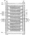
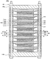
- FIG. 1 is a schematic cross-sectional view showing a fuel cell stack 100 according to a first embodiment.
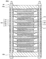
- 6 is a schematic cross-sectional view showing a fuel cell stack 100x according to Comparative Example 1.
- FIG. 6 is a schematic cross-sectional view showing a fuel cell stack 100x1 according to Comparative Example 2.
- FIG. 10 is a schematic cross-sectional view showing a fuel cell stack 100x2 according to Comparative Example 3.
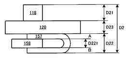
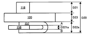
- FIG. It is a schematic cross section showing the dimension of the member of battery unit 103 before assembling (clamping). It is a schematic cross section showing the dimension of the member of battery unit 103 after assembling (clamping). It is a schematic cross section showing the dimension of the member of battery unit 103 before assembling (clamping).
- FIG. 1 is a schematic cross-sectional view showing a fuel cell stack (fuel cell) 100 according to a first embodiment.
- the fuel cell stack 100 includes a plurality of battery units 103, end plates 145a and 145b, and a fastening member 146.
- the battery unit 103 includes interconnectors 112 and 113, a single cell 120, an air chamber 116, a fuel chamber 117, connection members 118 and 119, a frame member 161, a fuel electrode insulating seal member 163, and an air electrode insulating seal member 162.
- the interconnectors 112 and 113 have a square plate shape in plan view, are formed of a conductive metal or the like, and are arranged vertically.
- the single cell 120 has an electrolyte, an air electrode, and a fuel electrode (not shown). An air electrode and a fuel electrode are disposed on the upper and lower surfaces of the electrolyte.
- the air chamber 116 and the fuel chamber 117 are spaces to which oxidant gas and fuel gas are supplied, respectively.
- connection member 118 is a connection member (current collection member) that is disposed in the air chamber 116 and electrically connects the air electrode 114 of the single cell 120 and the interconnector 112.
- the connecting member 119 is a connecting member (current collecting member) that is disposed inside the fuel chamber 117 and electrically connects the fuel electrode 115 of the single cell 120 and the interconnector 113.
- a gap between the connecting members 118 forms a part of the air chamber 116, and the oxidant gas contacts the air electrode 114.
- the gap between the connection members 119 forms part of the fuel chamber 117, and the fuel gas contacts the fuel electrode 115.
- the frame member 161 has an opening, and the single cell 120 is disposed in the opening.
- the frame member 161 is divided into an air chamber 116 side and a fuel chamber 117 side where the single cell 120 is disposed.
- the frame member 161 corresponds to a combination of a cell frame 122 and a separator 123 in the examples described later.
- the air electrode insulating seal member 162 is a frame-shaped insulating member that insulates and seals the air electrode 114 side of the frame member 161.
- the air electrode insulating seal member 162 corresponds to the air electrode insulating frame 124 of the embodiment described later.
- the fuel electrode insulating seal member 163 is a frame-shaped insulating member that insulates and seals the fuel electrode 115 side of the frame member 161.
- the fuel electrode insulation seal member 163 corresponds to the fuel electrode insulation frame 121 of the embodiment described later.
- the end plates 145a and 145b sandwich the stacked battery units 103 from above and below.
- the fastening member 146 is composed of, for example, a combination of bolts and nuts, and fastens the stacked battery units 103 in the stacking direction and applies a tightening pressure. By applying the clamping pressure to the battery unit 103, the contact resistance in the fuel cell stack 100 (for example, between the connection member 119 and the single cell 120) can be reduced.
- the thickness of at least one connection member 119 among the plurality of connection members 119 is different from the thickness of the other connection members 119.
- the thickness of the connection member 119 disposed between the interconnectors 112 and 113 even if there is a variation in the thickness of the single cell 120, there is a difference between the connection member 119 and the single cell 120.
- the contact resistance can be reduced.
- the shortest distance D1 between the upper surface (front surface) of the interconnector 113 and the lower surface (back surface) of the interconnector 112, the total thickness D2 of the thicknesses of the connection members 118 and 119 and the thickness of the single cell 120 correspond. To do.
- the distance D1 is the thickness D11 of the frame member 161 (the thickness D11 includes the thickness of the separator 123, the same applies hereinafter), and the thickness of the air electrode insulating seal member 162.
- D12 is defined by the sum of the thickness D13 of the fuel electrode insulating seal member 163.
- D1 D11 + D12 + D13 (1)
- the total thickness D2 is the sum of the thicknesses D21 and D22 of the connection members 118 and 119 and the thickness D23 of the single cell 120.
- D2 D21 + D22 + D23 (2)
- the thicknesses D11, D12, D13, D21, D22, and D23 are values before being tightened by the tightening member 146.
- the tightening member 146 for example, a bolt and a nut are used.
- the tightening member 146 fastens and fixes the plurality of battery units 103 to 103 in the stacking direction at the separator 123 and the frame member 161.
- the difference (D2 ⁇ D1) between the distance D1 and the total thickness D2 is “0 ⁇ (D2 ⁇ D1) ⁇ 200 ⁇ m”, these may correspond to each other.
- the distance D1 corresponds to the total thickness D2
- the contact resistance between the connection member 119 and the single cell 120 can be reduced even when the thickness of the single cell 120 varies.
- FIG. 2 to 4 are schematic cross-sectional views showing the fuel cell stacks 100x, 100x1, and 100x2 according to Comparative Examples 1 to 3.
- FIG. 2 to 4 are schematic cross-sectional views showing the fuel cell stacks 100x, 100x1, and 100x2 according to Comparative Examples 1 to 3.
- FIG. 2 to 4 are schematic cross-sectional views showing the fuel cell stacks 100x, 100x1, and 100x2 according to Comparative Examples 1 to 3.
- the thickness of the constituent elements of the battery unit 103 may be variations in the thickness of the constituent elements of the battery unit 103 (for example, the single cell 120).
- the single cell 120 is not electrically connected to one (or both) of the interconnectors 112 and 113. There can be.
- the single cell 120 does not contact the connection member 119, and the single cell 120 and the interconnector 113 are not electrically connected.
- the thickness can be adjusted for each battery unit 103, the pressure distribution in the fuel cell stack 100 is made uniform, and the damage of the member is reduced.
- the thickness can be adjusted for each battery unit 103, the deformation is dispersed in each battery unit 103, the stress accompanying the deformation of the member is reduced, and the probability that the member (for example, the single cell 120) is broken can be reduced. .
- the contact resistance in the battery unit 103 (for example, between the connection member 119 and the single cell 120) is defined by the contact pressure between them.
- This contact pressure is determined by the shortest distance D1 between the upper surface of the interconnector 113 and the lower surface of the interconnector 112 (the thickness D11 of the frame member 161, the thickness D12 of the air electrode insulating seal member 162, the thickness of the fuel electrode insulating seal member 163).
- the contact pressure can be adjusted appropriately.
- the difference (D2 ⁇ D1) is large, for example, the contact pressure between the connection member 119 and the single cell 120 cannot be substantially adjusted, and in some cases, the contact pressure itself cannot be applied (Comparative Example 2 described above).
- the small difference (D2 ⁇ D1) is important in reducing the contact resistance by adjusting the tightening pressure at the tightening member 146.
- the contact pressure can be adjusted by the thickness of the seal members (frame member 161, air electrode insulating seal member 162, fuel electrode insulating seal member 163).
- the thickness of the sealing member itself may change, which may affect the sealing performance.
- the contact pressure is controlled by adjusting the thickness of the connection member 119. For this reason, the contact pressure can be controlled without affecting the sealing performance.
- the contact pressure may be controlled by adjusting the thickness of the connection member 118 on the air electrode side of the single cell instead of the connection member 119 on the fuel electrode side of the single cell.
- the thickness of the connecting member on the fuel electrode side of the single cell of at least one battery unit of the plurality of battery units is different from the thickness of the connecting member on the fuel electrode side of the single cell of another battery unit.
- the thickness of the connection member on the air electrode side of the single cell of at least one battery unit of the plurality of battery units is different from the thickness of the connection member on the air electrode side of the single cell of another battery unit.
- 5A and 5B show the dimensions of the members of the battery unit 103 before and after assembly (clamping), respectively.
- the thickness of the air electrode insulating frame 124 and the fuel electrode insulating frame 121 is decreased from D12 to D121 and from D13 to D131, respectively. Since the air electrode insulating frame 124 and the fuel electrode insulating frame 121 are made of an elastic material such as mica, the thickness is reduced by tightening at the time of stack formation.
- the thickness D10 set as the distance between the interconnectors is the distance between the surface of the interconnector of one battery unit and the back surface of the interconnector of another battery unit stacked in this one battery unit. As the set thickness and indicates the shortest distance between the interconnectors after the fuel cell is formed. After the production of the fuel cell, the connection member for each cell may contract (thickness decreases) by tightening, and it is preferable to consider the contraction.
- 5C and 5D show the dimensions of the members of the battery unit 103 before and after assembly (clamping), respectively.
- the thickness of the adjusting member 158 decreases from D221 to D221a by tightening with the tightening member 146. Since the adjusting member 158 is made of an elastic material such as mica, the thickness is reduced by tightening at the time of stack creation.
- D22 thickness of current collector 157 (total thickness of current collector 157 and adjustment member 158)
- D23 Thickness of single cell 120
- D22a Total thickness of current collector 157 and adjusting member 158 after tightening
- D221a Thickness of adjusting member 158 after tightening
- Ac2 Shrinkage rate of adjusting member 158
- ⁇ Adjustment member 158 contracts due to the pressurization during stack assembly.
- the standard is that the difference between the distance D10 after the tightening and the total thickness D20 (D20 ⁇ D10) is “0 ⁇ (D20 ⁇ D10) ⁇ 200 ⁇ m”.
- FIG. 6 is a schematic cross-sectional view showing a fuel cell stack 100a according to the second embodiment of the present invention.
- the connection member 119 has an adjustment member 158. That is, the thickness of the connecting member 119 can be adjusted only by the thickness of the adjusting member 158, not the entire connecting member 119. That is, the adjustment member 158 corresponding to the thickness of the single cell 120 is inserted into the current collector 157 to constitute the connection member 119 having a structure in which the adjustment member 158 and the current collector 157 are combined.
- the adjusting member 158 can be an insulating material (for example, mica). That is, the connecting member 119 that electrically connects the interconnector 113 and the single cell 120 can be configured by a structure in which the insulating adjusting member 158 and the conductive current collector 157 are combined.
- the connecting member 118 on the air electrode side of the single cell 120 has an adjusting member, and the contact pressure is adjusted by adjusting the thickness of the adjusting member. May be controlled.
- the following manufacturing method of the embodiment of the present invention is an embodiment in the case of adjusting the thickness of the connecting member on the fuel electrode side.
- the present invention is not limited to this.
- the thickness of the connection member on the air electrode side may be adjusted.
- connection members 119 to 119 having a plurality of types of thicknesses are prepared in advance.
- connection members 119 to 119 are prepared every 50 ⁇ m.
- a plurality of types of adjustment members 158 having a plurality of types of thicknesses are prepared in advance instead of the connection members 119 having a plurality of types of thicknesses.
- the thickness D23 of the single cell 120 is measured.
- the thickness D23 of the single cell 120 can be measured with a micrometer.
- connection member 119 having a thickness corresponding to thickness D23 of single cell 120 is selected.
- the thickness D10 is set as the distance between the interconnectors 112 and 113.
- the thickness D10 is obtained by adding a set value Dc to the sum D1 of standard values of the thickness D11 of the frame member 161, the thickness D12 of the air electrode insulating seal member 162, and the thickness D13 of the fuel electrode insulating seal member 163. It is a thing.
- this subtraction value corresponds to the sum of the thicknesses of the connecting member 118 and the connecting member 119 (D21 + D22).
- the thickness may be adjusted only with the connecting member 119.
- the thickness of the connection member 118 is measured, and a subtraction value (D10 ⁇ D23 ⁇ D21) is calculated.
- connection member 119 having a thickness corresponding to this subtraction value (D10-D23-D21) is selected.
- a part of the adjustment member 158 is selected instead of the entire connection member 119.
- the shrinkage rate Ac2 of the adjustment member 158 as the thickness D22 of the connection member 119 as follows.
- the connection member 119 having a thickness corresponding to the thickness D23 of the single cell 120 is selected.
- the thickness (contact pressure) can be adjusted for each battery unit 103.
- the contact resistance inside the fuel cell stack 100 is reduced, and damage to members due to stress concentration can be prevented.
- connection member 119 has an adjustment member 158, and the thickness of the connection member 119 can be adjusted only by the adjustment member 158.
- the combination of the cell frame 122 and the separator 123 corresponds to the frame member 161 in the embodiment.
- the air electrode insulating frame 124 and the fuel electrode insulating frame 121 correspond to the air electrode insulating seal member 162 and the fuel electrode insulating seal member 163 in the embodiment.
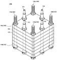
- the fuel cell stack 100b includes a battery unit 103, an air supply channel 104, an air exhaust channel 105, a fuel supply channel 106, a fuel exhaust channel 107, and a fixing member 109.
- the battery unit 103 is a minimum unit of power generation, and includes interconnectors 112 and 113, a single cell 120, an air chamber 116, a fuel chamber 117, and connection members 118 and 119.
- the interconnectors 112 and 113 are in the form of a square plate in plan view, are made of conductive ferritic stainless steel or the like, and are arranged vertically.
- the single cell 120 is located approximately in the middle of the interconnectors 112 and 113, and includes an electrolyte 102, an air electrode 114, and a fuel electrode 115.
- An air electrode 114 and a fuel electrode 115 are disposed on the upper and lower surfaces of the electrolyte 102.
- the electrolyte 102 is made of LaGaO 3 -based ceramic, BaCeO 3 -based ceramic, SrCeO 3 -based ceramic, SrZrO 3 -based ceramic, CaZrO 3 -based ceramic, etc. in addition to ZrO 2 -based ceramic.
- the material of the fuel electrode 115 is a ceramic such as a ZrO 2 ceramic such as zirconia or a CeO 2 ceramic stabilized by at least one of metals such as Ni and Fe and rare earth elements such as Sc and Y. And a mixture with at least one of the above.
- the material of the fuel electrode 115 may be a metal such as Pt, Au, Ag, Pb, Ir, Ru, Rh, Ni, and Fe. These metals may be only one kind, or two or more kinds of alloys. Also good. Furthermore, a mixture (including cermet) of these metals and / or alloys and at least one of each of the above ceramics may be mentioned. Moreover, the mixture etc. of metal oxides, such as Ni and Fe, and at least 1 type of each of the said ceramic are mentioned.
- the material of the air electrode 114 for example, various metals, metal oxides, metal double oxides, and the like can be used.
- the metal include metals such as Pt, Au, Ag, Pb, Ir, Ru, and Rh, or alloys containing two or more metals.
- the metal oxide include oxides such as La, Sr, Ce, Co, Mn and Fe (La 2 O 3 , SrO, Ce 2 O 3 , Co 2 O 3 , MnO 2 and FeO). It is done.
- the double oxide a double oxide containing at least La, Pr, Sm, Sr, Ba, Co, Fe, Mn, etc.
- the air chamber 116 is a space that is disposed between the interconnector 112 and the air electrode 114 and is supplied with an oxidant gas.
- the air chamber 116 is formed by the separator 123, the air electrode insulating frame 124, and the collar interconnector 112.
- the separator 123 is made of a thin metal having conductivity, has a square frame shape, and the electrolyte 102 is attached to the lower surface thereof.
- the air electrode insulating frame 124 is a frame-shaped oxidant gas flow path forming insulating frame that is installed between the separator 123 and the upper interconnector 112 and surrounds the connection member 118. As described above, the air electrode insulating frame 124 corresponds to the air electrode insulating seal member 162 in the embodiment.
- the fuel chamber 117 is a space that is disposed between the interconnector 113 and the fuel electrode 115 and is supplied with fuel gas.
- the fuel chamber 117 is formed by a combination of the interconnector 113, the fuel electrode insulating frame 121, the cell frame 122, and the rod.
- the fuel electrode insulating frame 121 is a frame-shaped insulating frame for forming a fuel gas flow path that surrounds the connection member 119 and is installed on the lower surface of the lower interconnector 113. As described above, the fuel electrode insulating frame 121 corresponds to the fuel electrode insulating seal member 163 in the embodiment.
- the cell frame 122 has a frame shape and is installed on the upper surface of the fuel electrode insulating frame 121. As described above, the combination of the cell frame 122 and the separator 123 corresponds to the frame member 161 in the embodiment.
- the connecting member 118 is a connecting member that is disposed inside the air chamber 116 and electrically connects the air electrode 114 and the upper interconnector 112.
- connection member 118 on the air chamber 116 side has a long and narrow rectangular shape, and is formed of a dense conductive member such as stainless steel.
- a plurality of connection members 118 are in contact with the air electrode 114 on the upper surface of the electrolyte 102 and the lower surface (inner surface) of the upper interconnector 112, and are arranged in parallel and at regular intervals.
- the connecting member 118 on the air chamber 116 side may have the same structure as the connecting member 119 on the fuel chamber 117 side.
- the connecting member 119 is a connecting member that is disposed inside the fuel chamber 117 and electrically connects the fuel chamber 117 and the lower interconnector 113.
- the connection member 119 has a structure in which a conductive current collector 157 and an insulating adjustment member 158 are combined.
- the current collector 157 is formed of, for example, a Ni plate material, and includes a connector contact portion 157a, a single cell contact portion 157b, and a connecting portion 157c.
- the connector abutment portion 157a and the single cell abutment portion 157b are urged toward the interconnector 113 and the single cell 120 by the elasticity of the U-shaped portion of the connecting portion 157c, respectively, and the temperature cycle, fuel pressure / air pressure It is possible to flexibly follow the deformation of the single cell 120 due to such fluctuations.
- the connector contact portion 157a and the single cell contact portion 157b contact the lower interconnector 113 and the fuel electrode 115 of the single cell 120, respectively.
- the connecting portion 157c is a U-shaped member that connects the connector contact portion 157a and the single cell contact portion 157b.
- the connector abutting portion 157a and the single cell abutting portion 157b are urged toward the interconnector 113 and the single cell 120, respectively, by the elasticity of the U-shaped portion of the connecting portion 157c, and the temperature cycle, fuel pressure / air pressure It is possible to flexibly follow the deformation of the single cell 120 due to such fluctuations.
- the current collector 157 may be formed of, for example, a porous metal made of Ni, a wire mesh, or a wire, in addition to the case of forming the current collector 157 from a plate material. Further, the current collector 157 may be made of a metal resistant to oxidation such as Ni alloy or stainless steel in addition to Ni.
- the connecting member 119 is provided with an adjusting member 158 as shown in FIG.
- the adjustment member 158 is disposed in the fuel chamber 117 between the single cell 120 and the lower interconnector 113, between the connector contact portion 157a and the single cell contact portion 157b.
- the soot adjustment member 158 is formed of a material that does not sinter with the current collector 157 in the fuel cell operating temperature range. Therefore, there is no possibility that the single cell contact part 157b and the connector contact part 157a directly contact and sinter, and the single cell contact part 157b and the connector contact part 157a may sinter via the adjustment member 158. Nor.
- the material of the adjusting member 158 that satisfies the above conditions may be any of mica, alumina, alumina felt, vermiculite, carbon fiber, silicon carbide fiber, silica, or at least one of them as a main component. Good.
- the battery unit 103 includes an air supply unit 125, an air exhaust unit 126, a fuel supply unit 127, and a fuel exhaust unit 128.
- the air supply unit 125 includes an air supply channel 104 that supplies air into the air chamber 116.
- the air supply unit 125 includes an air supply through hole 129, an air supply communication chamber 130, a partition wall 131, an air supply communication unit 132, and the air supply channel 104.
- the air supply through hole 129 is opened in the vertical direction at the center of one side of the square battery unit 103.
- the air supply communication chamber 130 is a long hole-like space opened in the air electrode insulating frame 124 so as to communicate with the air supply through hole 129.
- the partition wall 131 partitions the air supply communication chamber 130 and the air chamber 116.
- the air supply communication unit 132 is formed by recessing a plurality of upper surfaces of the partition wall 131 at equal intervals.
- the air supply channel 104 is inserted into the air supply hole 129 and supplies air to the air supply communication chamber 130 from the outside.
- the air exhaust unit 126 includes an air exhaust through hole 133, an air exhaust communication chamber 134, an air exhaust communication unit 136, and an air exhaust channel 105.
- the air exhaust hole 133 is opened in the vertical direction at the center of one side opposite to the air supply unit 125 of the battery unit 103.
- the air exhaust communication part 136 is a long hole-shaped section opened in the air electrode insulating frame 124 so as to communicate with the air exhaust through hole 133.
- the air exhaust communication portion 136 is formed by recessing a plurality of upper surfaces of the partition walls 135 partitioning the air exhaust communication chamber 134 and the air chamber 116 at equal intervals.
- the air exhaust channel 105 is a tubular channel that is inserted into the air exhaust hole 133 and exhausts air from the air exhaust communication chamber 134 to the outside.
- the fuel supply unit 127 includes a fuel supply through hole 137, a fuel supply communication chamber 138, a fuel supply communication unit 140, and a fuel supply channel 106.
- the fuel supply through hole 137 is opened in the vertical direction at the center of one side of the remaining two sides of the square battery unit 103.
- the fuel supply communication chamber 138 is a long hole-shaped section opened in the fuel electrode insulating frame 121 so as to communicate with the fuel supply through hole 137.
- the fuel supply communication unit 140 is formed by recessing a plurality of upper surfaces of the partition walls 139 partitioning the fuel supply communication chamber 138 and the fuel chamber 117 at equal intervals.
- the fuel supply channel 106 is a tubular channel that is inserted into the fuel supply hole 137 and supplies fuel gas from the outside to the fuel supply communication chamber 138.
- the fuel exhaust unit 128 includes a fuel exhaust passage 107 that discharges fuel gas from the fuel chamber 117 to the outside.
- the fuel exhaust unit 128 includes a fuel exhaust passage 141, a fuel exhaust communication chamber 142, a partition wall 143, a fuel exhaust communication unit 144, and a fuel exhaust flow path 107.
- the fuel exhaust hole 141 is opened in the up-down direction at the center of one side opposite to the fuel supply unit 127 of the battery unit 103.
- the fuel exhaust communication chamber 142 is a long hole-like space opened in the fuel electrode insulating frame 121 so as to communicate with the fuel exhaust passage hole 141.
- the partition wall 143 partitions the fuel exhaust communication chamber 142 and the fuel chamber 117.
- the fuel exhaust communication part 144 is formed by recessing a plurality of upper surfaces of the partition wall 143 at equal intervals.
- the fuel exhaust passage 107 is inserted into the fuel exhaust passage 141 and discharges fuel gas from the fuel exhaust communication chamber 142 to the outside.
- the fuel cell stack 100 is configured by stacking a plurality of battery units 103 to form a cell group, and fixing the cell group with a fixing member 109.
- the interconnector 112 above the battery unit 103 positioned below and the interconnector 113 below the battery unit 103 mounted thereon are integrated into upper and lower battery units.
- 103 and 103 are shared.
- the fixing member 109 is a combination of a pair of end plates 145a and 145b and four sets of fastening members 146a to 146d.
- the pair of end plates 145a and 145b sandwich the top and bottom of the cell group.
- the fastening members 146a to 146d fasten the end plates 145a and 145b and the cell group with bolts and nuts through the corner holes (not shown) of the end plates 145a and 145b and the corner through holes 147 of the cell group.
- the material of the fastening members 146a to 146d is, for example, Inconel 601.
- the air supply flow path 104 is attached to the fuel cell stack 100 so as to penetrate vertically through the through holes (not shown) of the end plates 145a and 145b and the air supply through holes 129 of the cell group.
- FIG. 10 is a schematic cross-sectional view showing a part of the cell unit 103a of the fuel cell stack according to the modification of the present invention.
- the battery unit 103a includes interconnectors 112 and 113a, a cell frame 122, a separator 123, and an air electrode insulating frame 124.
- the battery unit 103a does not have the fuel electrode insulating frame 121.
- the interconnector 113a has a protrusion.
- the interconnector 113a may not have a protrusion, and the cell frame 122 may have a protrusion. In this case, the thickness of the interconnector 113a replaces the protrusion of the interconnector 113a and the fuel electrode insulating frame 121.
- each thickness should just be adjusted in each structural member of the battery unit 103a, and both the interconnector 113a and the self frame 122 do not need to have a protrusion.
- the interconnector 112, the cell frame 122, and the separator 123 are laser-welded as necessary.
- the single cell 120, the air chamber 116, the fuel chamber 117, the connecting members 118, 119, etc. are not shown.
- the fuel cell stack may be configured by excluding one of the fuel electrode insulating frame 121 and the air electrode insulating frame 124.
- Embodiments of the present invention are not limited to the above-described embodiments, and can be expanded and modified.
- the expanded and modified embodiments are also included in the technical scope of the present invention.
- the contact pressure may be controlled by adjusting the thickness of the connecting member 118.
- a frame-shaped frame (frame member (cell frame, separator), air electrode insulation seal member (air electrode insulation frame), fuel electrode insulation seal member (fuel electrode insulation) Frame)) is arranged. Some or all of these can be integrated. Further, a frame-shaped frame may be integrated with the interconnectors 112 and 113.
- the connecting member is a current collector as a member different from the interconnector, but is not limited thereto.
- the connecting member may be a convex-shaped current collector formed integrally with the interconnector. That is, the connection member also includes a convex portion (that is, a current collector integrated with the interconnector) for electrical connection with the surface of the electrode (fuel electrode or air electrode) of the single cell.
Landscapes
- Life Sciences & Earth Sciences (AREA)
- Engineering & Computer Science (AREA)
- Manufacturing & Machinery (AREA)
- Sustainable Development (AREA)
- Sustainable Energy (AREA)
- Chemical & Material Sciences (AREA)
- Chemical Kinetics & Catalysis (AREA)
- Electrochemistry (AREA)
- General Chemical & Material Sciences (AREA)
- Fuel Cell (AREA)
Abstract
Description
特許文献1では、カバープレートと板状体との間に加圧部材を備えることで、膜電極接合体と集電体との間の接触抵抗の低減を図っている。
特許文献2では、ワッシャプレートと、皿ばねによって、締め付け力を印加し、接触抵抗の低減を図っている。
しかし、燃料電池スタックを構成する部材は、厚み寸法にバラツキを有するのが通例である。このように、厚み寸法にバラツキを有する部材を積層した場合、締め付け圧力を印加しても、接触抵抗が充分に低減されるとは限らない。
本発明は、接触抵抗の低減が容易な燃料電池およびその製造方法を提供することを目的とする。
(1)本発明の一態様に係る燃料電池は、表面と裏面とを有する導電性のインターコネクタと、前記インターコネクタと電気的に接続される、接続部材と、燃料極と電解質と空気極とを有し、前記接続部材と電気的に接続される、単セルと、前記単セルの外周部と接続される開口を有する、セパレータと、を少なくとも有する電池単位、を複数積層し、前記複数の電池単位を、積層方向に締付けてなる燃料電池において、前記複数の電池単位の少なくとも1の電池単位の接続部材の厚さが、他の電池単位の接続部材の厚さと異なる、ことを特徴とする燃料電池である。
(i)前記複数の電池単位の少なくとも1の電池単位の単セルの燃料極側の接続部材の厚さが、他の電池単位の単セルの燃料極側の接続部材の厚さと異なる。
(ii)前記複数の電池単位の少なくとも1の電池単位の単セルの空気極側の接続部材の厚さが、他の電池単位の単セルの空気極側の接続部材の厚さと異なる。
導電性の集電体が、弾性力を有することによって、インターコネクタと単セル間での電気的接続を、好適に確保できる。
絶縁性の調整部材と、導電性の集電体と、の組み合わせによって、インターコネクタと単セル間での電気的接続を、更に好適に確保できる。
燃料極側に接続部材を配置することで、接続部材の材料選定が容易となる。即ち、燃料極側は還元性雰囲気であり、酸化の畏れがないので、耐酸化性を気にせず接続部材の材料を選定できる。
をさらに有し、
前記締付け部材は、前記セパレータ及び前記フレームにおいて、前記複数の電池単位を締付ける燃料電池としても良い。
これにより、インターコネクタと単セル間での電気的接続を、更に好適に確保できる。
(8)本発明の一態様に係る燃料電池は、表面と裏面とを有する導電性のインターコネクタと、前記インターコネクタと電気的に接続される、接続部材と、燃料極と電解質と空気極とを有し、前記接続部材と電気的に接続される、単セルと、前記単セルの外周部と接続される開口を有する、セパレータと、を少なくとも有する電池単位、を複数積層する工程を有する燃料電池の製造方法であって、複数の種類の厚さの接続部材を準備する工程と、前記単セルの厚さD23を測定する工程と、1の電池単位のインターコネクタの表面と、この1の電池単位に積層される他の電池単位のインターコネクタの裏面の間の距離として、設定された厚さD10からの前記測定された厚さD23の減算値に対応する、厚さを備える接続部材を、前記複数の種類の厚さの接続部材から選択する工程と、前記選択された接続部材を備える電池単位を積層する工程と、を、少なくとも有することを特徴とする。
D10=D1+Dc
となる。
D10=D11+D121+D131
=D11+(D12+D13)×Ac
D11:フレーム部材161の厚さ(セパレータ123の厚さも含む)
D12: 空気極絶縁シール部材の厚さ(締めつけ前(収縮前))
D121: 空気極絶縁シール部材の厚さ(締めつけ後(収縮後))
D13: 燃料極絶縁シール部材の厚さ(締めつけ前(収縮前))
D131: 燃料極絶縁シール部材の厚さ(締めつけ後(収縮後))
Ac: 絶縁シール部材の収縮率
(第1の実施の形態)
図1は、第1の実施の形態に係る燃料電池スタック(燃料電池)100を表す模式断面図である。燃料電池スタック100は、複数の電池単位103、エンドプレート145a、145b、締め付け部材146を有する。
単セル120は、電解質、空気極、燃料極を有する(図示せず)。電解質の上面、下面に空気極、燃料極が配置される。
接続部材119は、燃料室117の内部に配置され、単セル120の燃料極115とインターコネクタ113とを電気的に接続する接続部材(集電部材)である。
接続部材118間の隙間が、空気室116の一部を構成し、酸化剤ガスが空気極114に接触する。同様に、接続部材119間の隙間が、燃料室117の一部を構成し、燃料ガスが燃料極115に接触する。
締め付け部材146は、例えば、ボルトとナットの組み合わせから構成され、積層された電池単位103を積層方向に締め付け、締め付け圧力を印加する。電池単位103に締め付け圧力を印加することで、燃料電池スタック100内(例えば、接続部材119と単セル120間)での接触抵抗を低減できる。
D1=D11+D12+D13 …… 式(1)
D2=D21+D22+D23 …… 式(2)
締付け部材146は、例えば、ボルトおよびナットが用いられる。また、締付け部材146は、セパレータ123及びフレーム部材161の部分において、複数の電池単位103~103を積層方向に締め付けて固定する。
(i)前記複数の電池単位の少なくとも1の電池単位の単セルの燃料極側の接続部材の厚さが、他の電池単位の単セルの燃料極側の接続部材の厚さと異なる。
(ii)前記複数の電池単位の少なくとも1の電池単位の単セルの空気極側の接続部材の厚さが、他の電池単位の単セルの空気極側の接続部材の厚さと異なる。
D121=D12×Ac
D131=D13×Ac
Ac: 絶縁シール部材の収縮率(組み立て前後での寸法変化の割合)
D10=D11+D121+D131
=D11+(D12+D13)×Ac
D2 =D21+D23+D22
=D21+D23+D221+D222(=A+B)
D21 : 接続部材118の厚さ
D22 : 集電体157の厚さ
(集電体157と調整部材158の合計厚さ)
D221: 締め付け前の調整部材158の厚さ
D222: 集電体157単独の厚さ
D23 : 単セル120の厚さ
D20=D21+D23+D22a
=D21+D23+D221a+D222(=A+B)
=D21+D23+D221×Ac2+D222(=A+B)
D22a : 締め付け後の集電体157と調整部材158の合計厚さ
D221a: 締め付け後での調整部材158の厚さ
Ac2: 調整部材158の収縮率
図6は、本発明の第2の実施の形態に係る燃料電池スタック100aを表す模式断面図である。
ここでは、接続部材119が、調整部材158を有している。即ち、接続部材119全体では無く、調整部材158の厚さのみで、接続部材119の厚さを調節可能となる。即ち、単セル120の厚さに応じた調整部材158が、集電体157中に挿入されて、調整部材158と集電体157とを組み合わせた構造となる接続部材119を構成する。
燃料電池スタック100の製造方法を説明する。
本発明の実施形態の以下の製造方法では、燃料極側の接続部材について、厚さを調整する場合の実施形態である。ただし、これに限ることは無く、例えば、空気極側の接続部材について、厚さを調整しても良い。
複数の種類の厚さの接続部材119~119を予め準備しておく。例えば、50μmおきに接続部材119~119を用意する。なお、実施形態2の場合であれば、複数の種類の厚さの接続部材119に替えて、複数の種類の厚さの調整部材158を予め準備しておく。
単セル120の厚さD23を測定する。例えば、マイクロメータによって単セル120の厚さD23を測定できる。
単セル120の厚さD23に対応する厚さを有する接続部材119を選択する。
1)この選択に先立ち、インターコネクタ112、113間の距離として、厚さD10を設定しておく。この厚さD10は、例えば、フレーム部材161の厚さD11、空気極絶縁シール部材162の厚さD12、燃料極絶縁シール部材163の厚さD13の規格値の和D1に、設定値Dcを加えたものである。
D10=D1(=D11+D12+D13)+Dc
となる。
D10=D11+(D12+D13)×Ac
尚、厚さの調整を、接続部材119のみで、行ってもよい。この場合は、接続部材118の厚さを測定し、減算値(D10-D23-D21)を算出する。
D22a=D222+D221×Ac2=(D10-D21-D23)
D22=D222+D221
=D222+(D10-D21-D23-D222)/Ac2
選択された接続部材119を備える電池単位103を積層し、エンドプレート145a、145bで挟み、締め付け部材146で締め付ける。
この実施例は、第2の実施形態に対応し、接続部材119が、調整部材158を有し、調整部材158のみで、接続部材119の厚さを調節可能である。
空気極絶縁フレーム124は、セパレータ123と上のインターコネクタ112との間に設置されて、接続部材118の周りを囲う額縁形態の酸化剤ガス流路形成用絶縁フレームである。既述のように、空気極絶縁フレーム124は、実施形態での空気極絶縁シール部材162に対応する。
連接部157cのU字に曲がった部分の弾性によりコネクタ当接部157aと単セル当接部157bがそれぞれインターコネクタ113と単セル120に向けて付勢され、なおかつ、温度サイクルや燃料圧・空気圧などの変動による単セル120の変形に柔軟に追従し得る。
コネクタ当接部157a、単セル当接部157bはそれぞれ、下のインターコネクタ113および単セル120の燃料極115に当接する。
連接部157cは、コネクタ当接部157aと単セル当接部157bとをつなぐU字状の部材である。
連接部157cのU字に曲がった部分の弾性により、コネクタ当接部157aと単セル当接部157bがそれぞれインターコネクタ113と単セル120に向けて付勢されかつ、温度サイクルや燃料圧・空気圧などの変動による単セル120の変形に柔軟に追従し得る。
空気供給通孔129は、四角い電池単位103の一辺側中央に上下方向に開設される。
空気供給連絡室130は、空気供給通孔129に連通するように空気極絶縁フレーム124に開設した長孔状の空間である。
隔壁131は、空気供給連絡室130と空気室116の間を仕切る。
空気供給連絡部132は、隔壁131の上面を複数個等間隔に窪ませて形成される。
空気供給流路104は、空気供給通孔129に挿通して外部から空気供給連絡室130に空気を供給する。
空気排気通孔133は、電池単位103の空気供給部125の反対側の一辺側中央に上下方向に開設される。
空気排気連絡部136は、空気排気通孔133に連通するように空気極絶縁フレーム124に開設した長孔状の区画である。
空気排気連絡部136は、空気排気連絡室134と空気室116の間を仕切る隔壁135の上面を複数個等間隔に窪ませて形成される。
空気排気流路105は、空気排気通孔133に挿通して空気排気連絡室134から外部に空気を排出する管状の流路である。
燃料供給連絡室138は、燃料供給通孔137に連通するように燃料極絶縁フレーム121に開設した長孔状の区画である。
燃料供給連絡部140は、燃料供給連絡室138と燃料室117の間を仕切る隔壁139の上面を複数個等間隔に窪ませて形成される。
燃料供給流路106は、燃料供給通孔137に挿通して外部から前記燃料供給連絡室138に燃料ガスを供給する管状の流路である。
燃料排気通孔141は、電池単位103の燃料供給部127の反対側の一辺側中央に上下方向に開設される。
燃料排気連絡室142は、燃料排気通孔141に連通するように燃料極絶縁フレーム121に開設した長孔状の空間である。
隔壁143は、燃料排気連絡室142と燃料室117の間を仕切る。
燃料排気連絡部144は、隔壁143の上面を複数個等間隔に窪ませて形成される。
燃料排気流路107は、燃料排気通孔141に挿通して燃料排気連絡室142から外部に燃料ガスを排出する。
なお、電池単位103を複数セット積層した場合において、下に位置する電池単位103の上のインターコネクタ112と、その上に載る電池単位103の下のインターコネクタ113は、一体にして上下の電池単位103、103同士で共有する。
一対のエンドプレート145a、145bは、セル群の上下を挟む。
締め付け部材146a~146dは、エンドプレート145a、145bとセル群をエンドプレート145a、145bのコーナー孔(図示せず)とセル群の前記コーナー通孔147にボルトを通してナットで締め付ける。締め付け部材146a~146dの材質は、例えばインコネル601である。
図10は、本発明の変形例に係る燃料電池スタックの電池単位103aの一部を表す模式断面図である。
電池単位103aは、インターコネクタ112、113a、セルフレーム122、セパレータ123、空気極絶縁フレーム124を有する。前述の実施例と異なり、電池単位103aは、燃料極絶縁フレーム121を有しない。その代わりに、インターコネクタ113aは、突起を有する。但し、インターコネクタ113aが突起を有さず、セルフレーム122が突起を有しても良い。この場合、インターコネクタ113aの厚みが、インターコネクタ113aの突起及び燃料極絶縁フレーム121の代わりすることになる。
ここで、必要に応じて、インターコネクタ112、セルフレーム122、セパレータ123がレーザー溶接される。
なお、単セル120、空気室116、燃料室117、接続部材118、119等は記載を省略している。
以上のように、燃料極絶縁フレーム121、空気極絶縁フレーム124の一方を除外して、燃料電池スタックを構成しても良い。
本発明の実施形態は上記の実施形態に限られず拡張、変更可能であり、拡張、変更した実施形態も本発明の技術的範囲に含まれる。
Claims (8)
- 表面と裏面とを有する導電性のインターコネクタと、
前記インターコネクタと電気的に接続される、接続部材と、
燃料極と電解質と空気極とを有し、前記接続部材と電気的に接続される、単セルと、
前記単セルの外周部と接続される開口を有する、セパレータと、
を少なくとも有する電池単位、を複数積層し、
前記複数の電池単位を、積層方向に締付けてなる燃料電池において、
前記複数の電池単位の少なくとも1の電池単位の接続部材の厚さが、他の電池単位の接続部材の厚さと異なる、
ことを特徴とする燃料電池。 - 1の電池単位のインターコネクタの表面と、この1の電池単位に積層される他の電池単位のインターコネクタの裏面との間の最短距離D1と、前記1の電池単位の接続部材の厚さと、前記1の電池単位の単セルの厚さとの合計厚さD2と、の差(D2-D1)が、
0≦(D2-D1)≦200μmであることを特徴とする、
請求項1に記載の燃料電池。 - 1の電池単位のインターコネクタの表面と、この1の電池単位に積層される他の電池単位のインターコネクタの裏面との間の距離として、設定された厚さD10と、前記1の電池単位の接続部材の設定厚さと、前記1の電池単位の単セルの厚さとの合計厚さD20と、の差(D20-D10)が、
0≦(D20-D10)≦200μmであることを特徴とする、
請求項1に記載の燃料電池。 - 前記接続部材は、弾性力を有する、導電性の集電体であることを特徴とする、
請求項1乃至3のいずれか1項に記載の燃料電池。 - 前記接続部材は、少なくとも、絶縁性の調整部材と、導電性の集電体と、を
有することを特徴とする、
請求項1乃至3のいずれか1項に記載の燃料電池。 - 前記接続部材は、前記単セルの燃料極に接することを特徴とする、
請求項1乃至5の何れか1項に記載の燃料電池。 - 1の電池単位のインターコネクタと、この1の電池単位に積層される他の電池単位のインターコネクタの間に配置される、1つまたは複数の枠形状のフレームを有することを特徴とする、
請求項1乃至6の何れか1項に記載の燃料電池。 - 表面と裏面とを有する導電性のインターコネクタと、
前記インターコネクタと電気的に接続される、接続部材と、
燃料極と電解質と空気極とを有し、前記接続部材と電気的に接続される、単セルと、
前記単セルの外周部と接続される開口を有する、セパレータと、
を少なくとも有する電池単位、を複数積層する工程を有する燃料電池の製造方法であって、
複数の種類の厚さの接続部材を準備する工程と、
前記単セルの厚さD23を測定する工程と、
1の電池単位のインターコネクタの表面と、この1の電池単位に積層される他の電池単位のインターコネクタの裏面の間の距離として、設定された厚さD10からの前記測定された厚さD23の減算値に対応する、厚さを備える接続部材を、前記複数の種類の厚さの接続部材から選択する工程と、
前記選択された接続部材を備える電池単位を積層する工程と、
を有することを特徴とする燃料電池の製造方法。
Priority Applications (7)
| Application Number | Priority Date | Filing Date | Title |
|---|---|---|---|
| EP14748621.1A EP2955777B1 (en) | 2013-02-07 | 2014-02-05 | Fuel cell and method for manufacturing same |
| CA2900463A CA2900463C (en) | 2013-02-07 | 2014-02-05 | Fuel cell and method for manufacturing same |
| DK14748621.1T DK2955777T3 (da) | 2013-02-07 | 2014-02-05 | Brændselscelle og fremgangsmåde til fremstilling af samme |
| JP2014529745A JP6294826B2 (ja) | 2013-02-07 | 2014-02-05 | 燃料電池およびその製造方法 |
| KR1020157024049A KR101872078B1 (ko) | 2013-02-07 | 2014-02-05 | 연료 전지 및 그 제조 방법 |
| CN201480008062.5A CN104995779B (zh) | 2013-02-07 | 2014-02-05 | 燃料电池及其制造方法 |
| US14/766,271 US10224553B2 (en) | 2013-02-07 | 2014-02-05 | Fuel cell comprising connection members having different thickness for each of cell units and method for manufacturing same |
Applications Claiming Priority (2)
| Application Number | Priority Date | Filing Date | Title |
|---|---|---|---|
| JP2013022358 | 2013-02-07 | ||
| JP2013-022358 | 2013-02-07 |
Publications (1)
| Publication Number | Publication Date |
|---|---|
| WO2014123150A1 true WO2014123150A1 (ja) | 2014-08-14 |
Family
ID=51299742
Family Applications (1)
| Application Number | Title | Priority Date | Filing Date |
|---|---|---|---|
| PCT/JP2014/052655 Ceased WO2014123150A1 (ja) | 2013-02-07 | 2014-02-05 | 燃料電池およびその製造方法 |
Country Status (8)
| Country | Link |
|---|---|
| US (1) | US10224553B2 (ja) |
| EP (1) | EP2955777B1 (ja) |
| JP (1) | JP6294826B2 (ja) |
| KR (1) | KR101872078B1 (ja) |
| CN (1) | CN104995779B (ja) |
| CA (1) | CA2900463C (ja) |
| DK (1) | DK2955777T3 (ja) |
| WO (1) | WO2014123150A1 (ja) |
Cited By (6)
| Publication number | Priority date | Publication date | Assignee | Title |
|---|---|---|---|---|
| WO2016047048A1 (ja) * | 2014-09-22 | 2016-03-31 | 日本特殊陶業株式会社 | 固体酸化物形燃料電池スタック |
| JP2017004628A (ja) * | 2015-06-05 | 2017-01-05 | 本田技研工業株式会社 | 燃料電池スタック |
| JP2017228481A (ja) * | 2016-06-24 | 2017-12-28 | 日本特殊陶業株式会社 | 電気化学反応セルスタック |
| JP2018022653A (ja) * | 2016-08-05 | 2018-02-08 | トヨタ自動車株式会社 | 発電検査用装置 |
| KR101872083B1 (ko) | 2015-05-29 | 2018-06-27 | 도요타지도샤가부시키가이샤 | 조전지의 제조 방법 |
| JP2019003794A (ja) * | 2017-06-14 | 2019-01-10 | 日本特殊陶業株式会社 | 電気化学反応セルスタック |
Families Citing this family (7)
| Publication number | Priority date | Publication date | Assignee | Title |
|---|---|---|---|---|
| CN105210224B (zh) * | 2013-04-15 | 2019-06-18 | 日产自动车株式会社 | 燃料电池的制造方法和制造装置 |
| US11271221B2 (en) * | 2017-06-06 | 2022-03-08 | Morimura Sofc Technology Co.. Ltd. | Electrochemical reaction cell stack, interconnector-electrochemical reaction unit cell composite, and method for manufacturing electrochemical reaction cell stack |
| JP6870493B2 (ja) * | 2017-06-22 | 2021-05-12 | トヨタ自動車株式会社 | 燃料電池モジュール及びその製造方法、コネクタ |
| KR102157927B1 (ko) * | 2017-07-24 | 2020-09-18 | 주식회사 엘지화학 | 고체산화물 연료전지 |
| CN107742735B (zh) * | 2017-09-05 | 2021-08-31 | 上海清能合睿兹新能源科技有限公司 | 一种mea包胶的密封结构及其制造方法和使用方法 |
| JP6981220B2 (ja) * | 2017-12-14 | 2021-12-15 | トヨタ自動車株式会社 | 制御装置及び電池システム |
| CN111251222B (zh) * | 2020-04-28 | 2020-09-11 | 深圳市南科燃料电池有限公司 | 安装装置 |
Citations (13)
| Publication number | Priority date | Publication date | Assignee | Title |
|---|---|---|---|---|
| JP2000077080A (ja) * | 1998-09-01 | 2000-03-14 | Tokyo Gas Co Ltd | 平板型固体電解質燃料電池用インターコネクタ板 |
| JP2001143741A (ja) | 1999-09-03 | 2001-05-25 | Honda Motor Co Ltd | 燃料電池スタック |
| JP2005203283A (ja) * | 2004-01-16 | 2005-07-28 | Ngk Spark Plug Co Ltd | 固体電解質形燃料電池 |
| JP2005317241A (ja) * | 2004-04-27 | 2005-11-10 | Tokyo Gas Co Ltd | 支持膜式固体酸化物形燃料電池スタック及びその作製方法 |
| JP2005317291A (ja) * | 2004-04-27 | 2005-11-10 | Tokyo Gas Co Ltd | 支持膜式固体酸化物形燃料電池スタック及びその作製方法 |
| JP2006260994A (ja) * | 2005-03-17 | 2006-09-28 | Toyota Motor Corp | 燃料電池 |
| JP2007250281A (ja) * | 2006-03-14 | 2007-09-27 | Kyocera Corp | 燃料電池セルスタック装置、燃料電池セルスタック連結装置及び燃料電池 |
| WO2008041593A1 (en) * | 2006-09-27 | 2008-04-10 | Kyocera Corporation | Fuel battery cell stack and fuel battery |
| JP2008293843A (ja) * | 2007-05-25 | 2008-12-04 | Ngk Spark Plug Co Ltd | 固体電解質形燃料電池 |
| JP2010080428A (ja) * | 2008-08-27 | 2010-04-08 | Ngk Insulators Ltd | 固体酸化物型燃料電池、及び、その組立方法 |
| JP2011008959A (ja) | 2009-06-23 | 2011-01-13 | Toshiba Corp | 燃料電池 |
| JP2012028092A (ja) * | 2010-07-21 | 2012-02-09 | Ngk Spark Plug Co Ltd | 燃料電池スタックの製造方法 |
| WO2013001777A1 (ja) * | 2011-06-28 | 2013-01-03 | 日本特殊陶業株式会社 | 固体酸化物形燃料電池およびインターコネクタ |
Family Cites Families (7)
| Publication number | Priority date | Publication date | Assignee | Title |
|---|---|---|---|---|
| JP4442561B2 (ja) * | 2003-03-19 | 2010-03-31 | 日本ケミコン株式会社 | 積層コンデンサおよび積層コンデンサの製造方法 |
| DE102005022894A1 (de) | 2005-05-18 | 2006-11-23 | Staxera Gmbh | SOFC-Stapel |
| JP4966522B2 (ja) | 2005-07-28 | 2012-07-04 | 京セラ株式会社 | 燃料電池セルスタックにおける集電構造 |
| CA2648655C (en) * | 2006-05-29 | 2013-09-24 | Ngk Spark Plug Co., Ltd. | Solid electrolyte fuel cell stack |
| CA2724867C (en) * | 2008-10-02 | 2017-06-06 | Ngk Spark Plug Co., Ltd. | Solid oxide fuel cell apparatus |
| US20120000964A1 (en) * | 2010-07-01 | 2012-01-05 | Gm Global Technology Operations, Inc. | Battery tab joints and methods of making |
| JP5819099B2 (ja) * | 2011-05-11 | 2015-11-18 | 日本特殊陶業株式会社 | 固体酸化物形燃料電池 |
-
2014
- 2014-02-05 WO PCT/JP2014/052655 patent/WO2014123150A1/ja not_active Ceased
- 2014-02-05 KR KR1020157024049A patent/KR101872078B1/ko active Active
- 2014-02-05 EP EP14748621.1A patent/EP2955777B1/en active Active
- 2014-02-05 JP JP2014529745A patent/JP6294826B2/ja active Active
- 2014-02-05 CN CN201480008062.5A patent/CN104995779B/zh active Active
- 2014-02-05 US US14/766,271 patent/US10224553B2/en active Active
- 2014-02-05 CA CA2900463A patent/CA2900463C/en active Active
- 2014-02-05 DK DK14748621.1T patent/DK2955777T3/da active
Patent Citations (13)
| Publication number | Priority date | Publication date | Assignee | Title |
|---|---|---|---|---|
| JP2000077080A (ja) * | 1998-09-01 | 2000-03-14 | Tokyo Gas Co Ltd | 平板型固体電解質燃料電池用インターコネクタ板 |
| JP2001143741A (ja) | 1999-09-03 | 2001-05-25 | Honda Motor Co Ltd | 燃料電池スタック |
| JP2005203283A (ja) * | 2004-01-16 | 2005-07-28 | Ngk Spark Plug Co Ltd | 固体電解質形燃料電池 |
| JP2005317241A (ja) * | 2004-04-27 | 2005-11-10 | Tokyo Gas Co Ltd | 支持膜式固体酸化物形燃料電池スタック及びその作製方法 |
| JP2005317291A (ja) * | 2004-04-27 | 2005-11-10 | Tokyo Gas Co Ltd | 支持膜式固体酸化物形燃料電池スタック及びその作製方法 |
| JP2006260994A (ja) * | 2005-03-17 | 2006-09-28 | Toyota Motor Corp | 燃料電池 |
| JP2007250281A (ja) * | 2006-03-14 | 2007-09-27 | Kyocera Corp | 燃料電池セルスタック装置、燃料電池セルスタック連結装置及び燃料電池 |
| WO2008041593A1 (en) * | 2006-09-27 | 2008-04-10 | Kyocera Corporation | Fuel battery cell stack and fuel battery |
| JP2008293843A (ja) * | 2007-05-25 | 2008-12-04 | Ngk Spark Plug Co Ltd | 固体電解質形燃料電池 |
| JP2010080428A (ja) * | 2008-08-27 | 2010-04-08 | Ngk Insulators Ltd | 固体酸化物型燃料電池、及び、その組立方法 |
| JP2011008959A (ja) | 2009-06-23 | 2011-01-13 | Toshiba Corp | 燃料電池 |
| JP2012028092A (ja) * | 2010-07-21 | 2012-02-09 | Ngk Spark Plug Co Ltd | 燃料電池スタックの製造方法 |
| WO2013001777A1 (ja) * | 2011-06-28 | 2013-01-03 | 日本特殊陶業株式会社 | 固体酸化物形燃料電池およびインターコネクタ |
Cited By (13)
| Publication number | Priority date | Publication date | Assignee | Title |
|---|---|---|---|---|
| KR101931892B1 (ko) * | 2014-09-22 | 2018-12-21 | 니뽄 도쿠슈 도교 가부시키가이샤 | 고체 산화물형 연료 전지 스택 |
| JP2016066415A (ja) * | 2014-09-22 | 2016-04-28 | 日本特殊陶業株式会社 | 固体酸化物形燃料電池スタック |
| KR20170043626A (ko) * | 2014-09-22 | 2017-04-21 | 니뽄 도쿠슈 도교 가부시키가이샤 | 고체 산화물형 연료 전지 스택 |
| CN106716700A (zh) * | 2014-09-22 | 2017-05-24 | 日本特殊陶业株式会社 | 固体氧化物型燃料电池堆 |
| EP3200267A4 (en) * | 2014-09-22 | 2018-03-28 | NGK Spark Plug Co., Ltd. | Solid oxide fuel cell stack |
| WO2016047048A1 (ja) * | 2014-09-22 | 2016-03-31 | 日本特殊陶業株式会社 | 固体酸化物形燃料電池スタック |
| CN106716700B (zh) * | 2014-09-22 | 2019-08-06 | 日本特殊陶业株式会社 | 固体氧化物型燃料电池堆 |
| US11735758B2 (en) | 2014-09-22 | 2023-08-22 | Morimura Sofc Technology Co., Ltd. | Solid oxide fuel cell stack |
| KR101872083B1 (ko) | 2015-05-29 | 2018-06-27 | 도요타지도샤가부시키가이샤 | 조전지의 제조 방법 |
| JP2017004628A (ja) * | 2015-06-05 | 2017-01-05 | 本田技研工業株式会社 | 燃料電池スタック |
| JP2017228481A (ja) * | 2016-06-24 | 2017-12-28 | 日本特殊陶業株式会社 | 電気化学反応セルスタック |
| JP2018022653A (ja) * | 2016-08-05 | 2018-02-08 | トヨタ自動車株式会社 | 発電検査用装置 |
| JP2019003794A (ja) * | 2017-06-14 | 2019-01-10 | 日本特殊陶業株式会社 | 電気化学反応セルスタック |
Also Published As
| Publication number | Publication date |
|---|---|
| CA2900463A1 (en) | 2014-08-14 |
| EP2955777A1 (en) | 2015-12-16 |
| CN104995779A (zh) | 2015-10-21 |
| US10224553B2 (en) | 2019-03-05 |
| EP2955777B1 (en) | 2020-01-22 |
| JPWO2014123150A1 (ja) | 2017-02-02 |
| DK2955777T3 (da) | 2020-04-20 |
| CN104995779B (zh) | 2018-01-19 |
| KR101872078B1 (ko) | 2018-06-27 |
| CA2900463C (en) | 2018-02-27 |
| JP6294826B2 (ja) | 2018-03-14 |
| KR20150115894A (ko) | 2015-10-14 |
| EP2955777A4 (en) | 2016-11-02 |
| US20150372318A1 (en) | 2015-12-24 |
Similar Documents
| Publication | Publication Date | Title |
|---|---|---|
| JP6294826B2 (ja) | 燃料電池およびその製造方法 | |
| US9455453B2 (en) | Fuel cell, and fuel cell stack | |
| JP6317222B2 (ja) | 固体酸化物形燃料電池スタック | |
| CN102906920B (zh) | 固体氧化物燃料电池 | |
| WO2014123148A1 (ja) | 燃料電池 | |
| US9640804B2 (en) | Fuel cell, and fuel cell stack | |
| US9935321B2 (en) | Fuel cell and fuel cell stack | |
| JP6702585B2 (ja) | 平板型電気化学セルスタック | |
| JP5722742B2 (ja) | 燃料電池 | |
| JP6072554B2 (ja) | 燃料電池 | |
| JP5722739B2 (ja) | 燃料電池 | |
| JP6022368B2 (ja) | 燃料電池 | |
| JP2006269409A (ja) | 固体酸化物形燃料電池 | |
| CN112166518B (zh) | 电池堆装置 | |
| JP2025176906A (ja) | 電気化学装置 | |
| JP2017224525A (ja) | 集電部材−電気化学反応単セル複合体および電気化学反応セルスタック |
Legal Events
| Date | Code | Title | Description |
|---|---|---|---|
| ENP | Entry into the national phase |
Ref document number: 2014529745 Country of ref document: JP Kind code of ref document: A |
|
| 121 | Ep: the epo has been informed by wipo that ep was designated in this application |
Ref document number: 14748621 Country of ref document: EP Kind code of ref document: A1 |
|
| ENP | Entry into the national phase |
Ref document number: 2900463 Country of ref document: CA |
|
| WWE | Wipo information: entry into national phase |
Ref document number: 14766271 Country of ref document: US |
|
| NENP | Non-entry into the national phase |
Ref country code: DE |
|
| WWE | Wipo information: entry into national phase |
Ref document number: 2014748621 Country of ref document: EP |
|
| ENP | Entry into the national phase |
Ref document number: 20157024049 Country of ref document: KR Kind code of ref document: A |