WO2014123189A1 - 電池制御装置、電池制御システム、電池制御方法、および記録媒体 - Google Patents
電池制御装置、電池制御システム、電池制御方法、および記録媒体 Download PDFInfo
- Publication number
- WO2014123189A1 WO2014123189A1 PCT/JP2014/052767 JP2014052767W WO2014123189A1 WO 2014123189 A1 WO2014123189 A1 WO 2014123189A1 JP 2014052767 W JP2014052767 W JP 2014052767W WO 2014123189 A1 WO2014123189 A1 WO 2014123189A1
- Authority
- WO
- WIPO (PCT)
- Prior art keywords
- battery
- control
- control device
- power system
- state
- Prior art date
- Legal status (The legal status is an assumption and is not a legal conclusion. Google has not performed a legal analysis and makes no representation as to the accuracy of the status listed.)
- Ceased
Links
Images




Classifications
-
- H—ELECTRICITY
- H02—GENERATION; CONVERSION OR DISTRIBUTION OF ELECTRIC POWER
- H02J—ELECTRIC POWER NETWORKS; CIRCUIT ARRANGEMENTS OR SYSTEMS FOR SUPPLYING OR DISTRIBUTING ELECTRIC POWER; SYSTEMS FOR STORING ELECTRIC ENERGY
- H02J7/00—Circuit arrangements for charging or discharging batteries or for supplying loads from batteries
- H02J7/865—Battery or charger load switching, e.g. concurrent charging and load supply
-
- H—ELECTRICITY
- H02—GENERATION; CONVERSION OR DISTRIBUTION OF ELECTRIC POWER
- H02J—ELECTRIC POWER NETWORKS; CIRCUIT ARRANGEMENTS OR SYSTEMS FOR SUPPLYING OR DISTRIBUTING ELECTRIC POWER; SYSTEMS FOR STORING ELECTRIC ENERGY
- H02J3/00—Circuit arrangements for AC mains or AC distribution networks
- H02J3/28—Arrangements for balancing of the load in networks by storage of energy
- H02J3/32—Arrangements for balancing of the load in networks by storage of energy using batteries or super capacitors with converting means
-
- H—ELECTRICITY
- H02—GENERATION; CONVERSION OR DISTRIBUTION OF ELECTRIC POWER
- H02J—ELECTRIC POWER NETWORKS; CIRCUIT ARRANGEMENTS OR SYSTEMS FOR SUPPLYING OR DISTRIBUTING ELECTRIC POWER; SYSTEMS FOR STORING ELECTRIC ENERGY
- H02J3/00—Circuit arrangements for AC mains or AC distribution networks
- H02J3/38—Arrangements for feeding a single network from two or more generators or sources in parallel; Arrangements for feeding already energised networks from additional generators or sources in parallel
-
- H—ELECTRICITY
- H02—GENERATION; CONVERSION OR DISTRIBUTION OF ELECTRIC POWER
- H02J—ELECTRIC POWER NETWORKS; CIRCUIT ARRANGEMENTS OR SYSTEMS FOR SUPPLYING OR DISTRIBUTING ELECTRIC POWER; SYSTEMS FOR STORING ELECTRIC ENERGY
- H02J3/00—Circuit arrangements for AC mains or AC distribution networks
- H02J3/38—Arrangements for feeding a single network from two or more generators or sources in parallel; Arrangements for feeding already energised networks from additional generators or sources in parallel
- H02J3/381—Dispersed generators
-
- H—ELECTRICITY
- H02—GENERATION; CONVERSION OR DISTRIBUTION OF ELECTRIC POWER
- H02J—ELECTRIC POWER NETWORKS; CIRCUIT ARRANGEMENTS OR SYSTEMS FOR SUPPLYING OR DISTRIBUTING ELECTRIC POWER; SYSTEMS FOR STORING ELECTRIC ENERGY
- H02J7/00—Circuit arrangements for charging or discharging batteries or for supplying loads from batteries
- H02J7/34—Parallel operation in networks using both storage and other DC sources, e.g. providing buffering
- H02J7/35—Parallel operation in networks using both storage and other DC sources, e.g. providing buffering with light sensitive cells
-
- H—ELECTRICITY
- H02—GENERATION; CONVERSION OR DISTRIBUTION OF ELECTRIC POWER
- H02J—ELECTRIC POWER NETWORKS; CIRCUIT ARRANGEMENTS OR SYSTEMS FOR SUPPLYING OR DISTRIBUTING ELECTRIC POWER; SYSTEMS FOR STORING ELECTRIC ENERGY
- H02J7/00—Circuit arrangements for charging or discharging batteries or for supplying loads from batteries
- H02J7/80—Circuit arrangements for charging or discharging batteries or for supplying loads from batteries including monitoring or indicating arrangements
- H02J7/82—Control of state of charge [SOC]
-
- H—ELECTRICITY
- H02—GENERATION; CONVERSION OR DISTRIBUTION OF ELECTRIC POWER
- H02J—ELECTRIC POWER NETWORKS; CIRCUIT ARRANGEMENTS OR SYSTEMS FOR SUPPLYING OR DISTRIBUTING ELECTRIC POWER; SYSTEMS FOR STORING ELECTRIC ENERGY
- H02J2101/00—Supply or distribution of decentralised, dispersed or local electric power generation
- H02J2101/20—Dispersed power generation using renewable energy sources
-
- H—ELECTRICITY
- H02—GENERATION; CONVERSION OR DISTRIBUTION OF ELECTRIC POWER
- H02J—ELECTRIC POWER NETWORKS; CIRCUIT ARRANGEMENTS OR SYSTEMS FOR SUPPLYING OR DISTRIBUTING ELECTRIC POWER; SYSTEMS FOR STORING ELECTRIC ENERGY
- H02J2101/00—Supply or distribution of decentralised, dispersed or local electric power generation
- H02J2101/20—Dispersed power generation using renewable energy sources
- H02J2101/22—Solar energy
- H02J2101/24—Photovoltaics
-
- H—ELECTRICITY
- H02—GENERATION; CONVERSION OR DISTRIBUTION OF ELECTRIC POWER
- H02J—ELECTRIC POWER NETWORKS; CIRCUIT ARRANGEMENTS OR SYSTEMS FOR SUPPLYING OR DISTRIBUTING ELECTRIC POWER; SYSTEMS FOR STORING ELECTRIC ENERGY
- H02J3/00—Circuit arrangements for AC mains or AC distribution networks
- H02J3/38—Arrangements for feeding a single network from two or more generators or sources in parallel; Arrangements for feeding already energised networks from additional generators or sources in parallel
- H02J3/46—Controlling the sharing of generated power between the generators, sources or networks
- H02J3/50—Controlling the sharing of reactive power
-
- Y—GENERAL TAGGING OF NEW TECHNOLOGICAL DEVELOPMENTS; GENERAL TAGGING OF CROSS-SECTIONAL TECHNOLOGIES SPANNING OVER SEVERAL SECTIONS OF THE IPC; TECHNICAL SUBJECTS COVERED BY FORMER USPC CROSS-REFERENCE ART COLLECTIONS [XRACs] AND DIGESTS
- Y02—TECHNOLOGIES OR APPLICATIONS FOR MITIGATION OR ADAPTATION AGAINST CLIMATE CHANGE
- Y02E—REDUCTION OF GREENHOUSE GAS [GHG] EMISSIONS, RELATED TO ENERGY GENERATION, TRANSMISSION OR DISTRIBUTION
- Y02E10/00—Energy generation through renewable energy sources
- Y02E10/50—Photovoltaic [PV] energy
- Y02E10/56—Power conversion systems, e.g. maximum power point trackers
-
- Y—GENERAL TAGGING OF NEW TECHNOLOGICAL DEVELOPMENTS; GENERAL TAGGING OF CROSS-SECTIONAL TECHNOLOGIES SPANNING OVER SEVERAL SECTIONS OF THE IPC; TECHNICAL SUBJECTS COVERED BY FORMER USPC CROSS-REFERENCE ART COLLECTIONS [XRACs] AND DIGESTS
- Y02—TECHNOLOGIES OR APPLICATIONS FOR MITIGATION OR ADAPTATION AGAINST CLIMATE CHANGE
- Y02E—REDUCTION OF GREENHOUSE GAS [GHG] EMISSIONS, RELATED TO ENERGY GENERATION, TRANSMISSION OR DISTRIBUTION
- Y02E70/00—Other energy conversion or management systems reducing GHG emissions
- Y02E70/30—Systems combining energy storage with energy generation of non-fossil origin
Definitions
- the power system control device When determining the operation schedule of the secondary battery, the power system control device transmits the operation schedule to the secondary battery control system that controls the operation of the secondary battery.
- the battery control method of the present invention is a battery control method performed by a battery control device that controls the operation of a battery connected to a power system, Detecting battery-related information indicating either the state of the battery or the state of the connection point between the power system and the battery, Transmitting the battery-related information to an external device, and performing reception processing for receiving operation control information for controlling the operation of the battery from the external device at predetermined time intervals, A battery operation control process for controlling the operation of the battery based on the state of the power system and the operation control information is executed at a time interval shorter than the predetermined time interval.
- the battery control method of the present invention is a battery control method performed by a battery control system including a first control device that controls the operation of a battery connected to an electric power system, and a second control device that communicates with the first control device. Because The first control device detects battery-related information representing any one of a state of the battery and a state of a connection point between the power system and the battery, The first control device transmits the battery-related information to the second control device, and executes reception processing for receiving operation control information for controlling the operation of the battery from the second control device at predetermined time intervals.
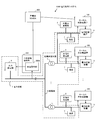
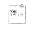
- Each local charging / discharging device 100 controls the charging / discharging operation of the corresponding power storage device 3.
- the local charge / discharge device 100 is an example of a first control device or a battery control device.
- the local charge / discharge device 100 controls the operation of the power storage device 3 connected to the power system 1.
- Local charging / discharging device 100 includes a detection unit 101, a communication unit 102, a frequency meter 103, and a calculation unit 104.
- the frequency meter 103 is an example of a second detection unit.
- the frequency meter 103 detects a system frequency (system frequency of the power system 1).
- the system frequency varies according to the power supply / demand balance state.
- the system frequency is an example of the state of the power system.
- the frequency meter 103 may be inside the local charging / discharging device 100 or outside.
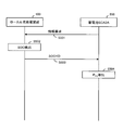
- the communication unit 102 receives the sharing information from the storage battery SCADA 200 after transmitting the SOC and ID of the power storage device 3 to the storage battery SCADA 200.
- the sharing information is set according to the unbalanced state of the demand and supply in the SOC and power of the power storage device 3.
- the sharing coefficient K and the maximum integrated value ⁇ f max of the frequency deviation are used as the sharing information.
- the sharing coefficient K increases as the sharing ratio to the power storage device 3 increases.
- the maximum value ⁇ f max of the integrated value of the frequency deviation is used as a threshold for the deviation amount of the system frequency with respect to the reference frequency (for example, 50 Hz).
- the reference frequency of the system frequency is stored in the calculation unit 104.
- the computing unit 104 obtains an integrated value ⁇ f of a frequency deviation that is a shift amount of the system frequency of the power system 1 with respect to a reference frequency of the system frequency.
- the calculation unit 104 uses the sharing coefficient K and the integrated value ⁇ f of the frequency deviation to use the power storage device 3. Controls the charging / discharging operation.
- the calculation unit 104 uses the sharing coefficient K and the maximum value ⁇ f max of the integrated value of the frequency deviation. The charge / discharge operation of the power storage device 3 is controlled.
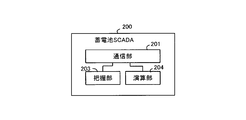
- the grasping unit 203 is an example of a grasping unit.
- the grasping unit 203 grasps the amount of power shared by the power storage device 3 under the management of the storage battery SCADA 200 in order to adjust the amount of power in the power system 1 (hereinafter referred to as “shared power amount”).
- the shared power amount is an example of the state of the power system.
- the power supply command unit 300A is an example of an external control device.
- the power supply command unit 300 ⁇ / b> A includes a frequency meter 301, a communication unit 302, and a calculation unit 303.
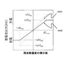
- Calculating unit 303 handles the capacity LFC ES as LFC assigned capacity LFC ES, LFC quota LFC ES and the charge-discharge gain curve showing a maximum value Delta] f max of the integrated value of frequency deviation predetermined (see FIG. 4 ) Is generated.
- the calculation unit 303 transmits the charge / discharge gain line from the communication unit 302 to the storage battery SCADA 200.
- P ES deriving operation the operation of storage battery SCADA 200 for deriving adjustable total capacity P ES based on the SOC of power storage device 3 (hereinafter referred to as “P ES deriving operation”) will be described.
- the adjustable total capacity P ES information such as the rated output P (n) of the storage battery of each ID (how many kWh is the battery. Also, the usable SOC range, for example, 30% to 90% Range). Since these pieces of information are basically static information, in this embodiment, it is assumed that the storage battery SCADA 200 has obtained these pieces of information from each local charge / discharge device 100 in advance.
- the calculation unit 204 receives the sharing information indicating the sharing coefficient K and the maximum value ⁇ f max of the integrated value of the frequency deviation shown in the latest charge / discharge gain line from the communication unit 201 to each local charging / discharging device. 100 (step S702).
- Equation 3 is used as the sharing coefficient K.
- a flexible such as instructing an individual storage battery as a value of the sharing coefficient K to forcibly output an output close to the limit when it is tight. Operation is possible.
- the local charging / discharging device 100 controls the operation of the power storage device 3 based on the integrated value ⁇ f of the frequency deviation and the sharing information (the sharing coefficient K and the maximum value ⁇ f max of the integrated value of the frequency deviation). . For this reason, it becomes possible to adjust operation
- the storage battery SCADA 200 may be realized by a computer.
- the computer reads and executes a program recorded on a computer-readable recording medium to execute each function of storage battery SCADA 200.
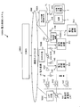
- the power control system 1000A uses the voltage of the SVR 1A5 to change the voltage of the SVR 1A5 with the fluctuation of the power generation amount of the solar power generation unit 2 depending on the weather, which is concerned about the power system 1A to which the solar power generation unit 2 is connected. It suppresses by controlling adjustment operation and charging / discharging operation
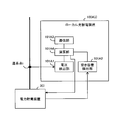
- the voltage detection unit 101A1 is an example of a first detection unit and a second detection unit.
- the voltage V i at the connection point i is an example of the state of the connection point i, the battery-related information, and the state of the power system 1A.
- the state of the connection point is not limited to the voltage at the connection point, and can be changed as appropriate. For example, the frequency, phase, or current of the connection point may be used as the state of the connection point.
- the period T g and the period T h is not limited to 10 minutes 0.1 seconds, the period T g may be longer than the period T h.
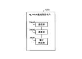
- the sensor built-in switch slave station 700A is an example of an external control device.
- the sensor built-in switch slave station 700A includes a voltage detection unit 700A1, a communication unit 700A2, and a calculation unit 700A3.
- the communication unit 700A2 communicates with the ESMS 200A.
- the SVR slave station 700B communicates with the ESMS 200A.
- SVR slave station 700B is the output voltage of SVR1A5, notifies the ESMS200A with a period T g, also continue to receive at a period T g the SVR YoSeiJo constant from ESMS200A.
- the SVR settling constant is information for specifying the output range (hereinafter referred to as “converted output range”) of the output voltage of the SVR 1A5 when the adjustment target voltage V T falls within the appropriate voltage range.
- the center value Vref (t) of the converted output range, the upper limit value Vref_high (t) of the converted output range, and the lower limit value Vref_low (t) of the converted output range are used as the SVR settling constants. Note that Vref (t) representing the center value of the converted output range may be omitted.
- the SVR slave station 700B sets the latest SVR settling constant in SVR1A5.
- the SVR 1A5 is an example of a voltage adjustment device.
- the SVR 1A5 The tap (not shown) is switched to change the adjustment target voltage VT to an appropriate voltage range.
- the settling time Ts is an example of a specific time.
- the grasping unit 200A2 is an example of a grasping unit.
- the grasping unit 200A2 grasps (stores) the information received by the communication unit 200A1 (the voltage V of each interconnection point, the free capacity Q of each power storage device 3, and the adjustment target voltage V T ) in association with the reception time. To do.
- the adjustment target voltage V T is an example of the situation of the power system 1A.
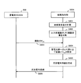
- setting operation for generating a setting constant for SVR and setting the setting constant for SVR in SVR 1A5
- the SVR slave station 700B detects the output voltage of the SVR 1A5 and transmits the output voltage of the SVR 1A5 to the ESMS 200A (step S1603).
- the grasping unit 200A2 receives the communication unit 200A1. association with storing the output voltage to be adjusted voltage V T and SVR1A5 each other.
- the arithmetic unit 200A3 derives SVR settling constants (Vref (t), Vref_high (t), and Vref_low (t)) based on the adjustment target voltage V T in the grasping unit 200A2 and the output voltage of the SVR 1A5. (Step S1604).
- the arithmetic unit 200A3 transmits the SVR settling constant from the communication unit 200A1 to the SVR slave station 700B (step S1605).
- the SVR slave station 700B When receiving the SVR settling constant, the SVR slave station 700B sets the SVR settling constant in SVR1A5 (step S1606). When the SVR settling constant is already set in the SVR 1A5, the SVR slave station 700B updates the SVR settling constant set in the SVR 1A5 to the latest SVR settling constant.
- the SVR 1A5 switches the tap of the SVR 1A5 to output the output voltage of the SVR 1A5. And the output voltage of SVR1A5 is changed to a voltage within the converted output range.
- the SVR 1A5 switches the tap of the SVR 1A5 to switch the SVR 1A5.
- the output voltage is raised and the output voltage of SVR1A5 is changed to a voltage within the converted output range.
- the settling time Ts may be a preset value, or may be changed with the passage of time in consideration of the life extension of the SVR 1A5 and the secular change of the SVR 1A5.
- the voltage of the power system 1A is adjusted by the operation of the SVR 1A5, the regenerative power supply whose power generation amount varies irregularly according to the weather, for example, a high-speed fluctuation component among the fluctuation components of the system voltage, for example, only by voltage adjustment by the SVR 1A5 It is not possible to cope with the components caused by the output of.
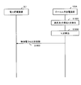
- the calculation unit 700A3 causes the voltage detection unit 700A1 to detect the adjustment target voltage V T (step S1701), and the adjustment target voltage V T detected by the voltage detection unit 700A1 is transmitted from the communication unit 700A2. It transmits to ESMS200A (step S1702).
- ESMS 200A every time communication unit 200A1 receives adjustment target voltage V T from sensor built-in switch slave station 700A, grasping unit 200A2 stores adjustment target voltage V T received by communication unit 200A1. Go.
- calculation unit 101A4 causes voltage detection unit 101A1 to detect voltage V at the connection point and holds voltage V (step S1704).
- V i at the interconnection point i will be described as an example.
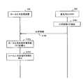
- the calculation unit 101A4 transmits the average value V i, AVE from the communication unit 101A3 to the ESMS 200A (step S1706).
- the arithmetic unit 200A3 includes, for each interconnection point, a plurality of average values V i, AVE (for example, ten average values V i, AVE in order from the newest) and a plurality of average values V T. , AVE (for example, 10 average values V T, AVE in order from the newest) are used to derive a correlation function.
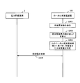
- FIG. 18 is a sequence diagram for explaining the power control operation.
- the calculation unit 101A4 performs the following calculation and adjusts from the voltage V i at the interconnection point i using the coefficients a i (t) and b i (t) of the correlation function included in the operation control information.
- the target voltage V T is calculated (step S1802).
- Voltage to be adjusted V T (t) a i (t) ⁇ V i (t) + b i (t)
- the calculation unit 101A4 determines the magnitude relationship between the calculated adjustment target voltage V T and the upper limit threshold value V mu and the lower limit threshold value V ml set in advance in the calculation unit 101A4.
- the reactive power amount Q i (t) is calculated according to the following formula.
- the calculation unit 101A4 outputs the calculated reactive power amount Q i (t) to the power storage device 3 (i) (step S1804).
- the calculation unit 101A4 determines that adjustment is not necessary, and charges / discharges the power storage device 3 (i). Do not control.
- Local rechargeable device 100 repeats steps S1801 ⁇ S1803 with a period T l.
- the local charge / discharge device 100A determines that the adjustment target voltage is the upper limit threshold V mu and the upper limit value of the appropriate voltage range of the adjustment target voltage V T.
- the operation of the power storage device 3 is controlled using the correlation information so as to be included in the range between the two.
- the local rechargeable device 100A when the calculation result of the adjustment target voltage is lower than the lower limit threshold value V ml is adjusted voltage, and the lower limit value of the proper voltage range of the lower limit threshold value V ml and adjusted voltage V T The operation of the power storage device 3 is controlled using the correlation information so as to be included in the range between the two.
- the ESMS 200A may be realized by a computer.
- the computer reads and executes a program recorded on a computer-readable recording medium and executes each function of the ESMS 200A.
Landscapes
- Engineering & Computer Science (AREA)
- Power Engineering (AREA)
- Supply And Distribution Of Alternating Current (AREA)
- Charge And Discharge Circuits For Batteries Or The Like (AREA)
- Remote Monitoring And Control Of Power-Distribution Networks (AREA)
- Secondary Cells (AREA)
Abstract
Description
前記電池の状態と、前記電力系統と前記電池との連系点の状態と、のいずれかを表す電池関連情報を検出する検出手段と、
前記検出手段の検出結果を外部装置に送信し、前記外部装置から前記電池の動作を制御するための動作制御情報を所定時間間隔で受信する受信処理を実行する第1通信手段と、
前記電力系統の状態と前記第1通信手段にて受信された動作制御情報とに基づいて前記電池の動作を制御する電池動作制御処理を前記所定時間間隔より短い時間間隔で実行する制御手段と、を含む。
前記第1制御装置は、
前記電池の状態と、前記電力系統と前記電池との連系点の状態と、のいずれかを表す電池関連情報を検出する検出手段と、
前記検出手段の検出結果を前記第2制御装置に送信し、前記第2制御装置から前記電池の動作を制御するための動作制御情報を所定時間間隔で受信する受信処理を実行する第1通信手段と、
前記電力系統の状態と前記第1通信手段にて受信された動作制御情報とに基づいて前記電池の動作を制御する電池動作制御処理を前記所定時間間隔より短い時間間隔で実行する制御手段と、を含み、
前記第2制御装置は、
前記第1制御装置と通信し、前記検出手段の検出結果を受信する第2通信手段と、
前記電力系統の状況を把握する把握手段と、
前記第2通信手段にて受信された検出手段の検出結果と、前記把握手段にて把握された電力系統の状況と、に基づいて、前記動作制御情報を生成し、当該動作制御情報を前記第2通信手段から前記第1制御装置に送信する処理手段と、を含む。
前記電池の状態と、前記電力系統と前記電池との連系点の状態と、のいずれかを表す電池関連情報を検出し、
前記電池関連情報を外部装置に送信し、前記外部装置から前記電池の動作を制御するための動作制御情報を所定時間間隔で受信する受信処理を実行し、
前記電力系統の状態と前記動作制御情報とに基づいて前記電池の動作を制御する電池動作制御処理を前記所定時間間隔より短い時間間隔で実行する。
前記第1制御装置が、前記電池の状態と、前記電力系統と前記電池との連系点の状態と、のいずれかを表す電池関連情報を検出し、
前記第1制御装置が、前記電池関連情報を前記第2制御装置に送信し、前記第2制御装置から前記電池の動作を制御するための動作制御情報を所定時間間隔で受信する受信処理を実行し、
前記第1制御装置が、前記電力系統の状態と前記動作制御情報とに基づいて前記電池の動作を制御する電池動作制御処理を前記所定時間間隔より短い時間間隔で実行し、
前記第2制御装置が、前記第1制御装置から前記電池関連情報を受信し、
前記第2制御装置が、前記電力系統の状況を把握し、
前記第2制御装置が、前記電池関連情報と前記電力系統の状況とに基づいて、前記動作制御情報を生成し、当該動作制御情報を前記第1制御装置に送信する。
電力系統に接続された電池の状態と、前記電力系統と前記電池との連系点の状態と、のいずれかを表す電池関連情報を検出する検出手順と、
前記電池関連情報を外部装置に送信し、前記外部装置から前記電池の動作を制御するための動作制御情報を所定時間間隔で受信する受信処理を実行する通信手順と、
前記電力系統の状態と前記動作制御情報とに基づいて前記電池の動作を制御する電池動作制御処理を前記所定時間間隔より短い時間間隔で実行する制御手順と、を実行させるためのプログラムを記録したコンピュータ読み取り可能な記録媒体である。
図1は、本発明の第1実施形態の電池制御システムを採用した電力制御システム1000を示す図である。




図12は、本発明の第2実施形態の電池制御システムを採用した電力制御システム1000Aを示す図である。図12において、図1または2に示したものと同一構成のものには同一符号を付してある。
相関関数:VT,AVE (t)= ai(t)・Vi,AVE(t)+bi(t)
本実施形態では、演算部200A3は、連系点ごとに、連系点における複数の平均値Vi,AVE(例えば新しい順に10個の平均値Vi,AVE)と、複数の平均値VT,AVE(例えば新しい順に10個の平均値VT,AVE)と、を用いて、相関関数を導出する。
調整対象電圧VT(t)= ai(t)・Vi(t)+bi(t)
続いて、演算部101A4は、算出された調整対象電圧VTと、予め演算部101A4に設定されている上限閾値Vmuおよび下限閾値Vmlと、の大小関係を判定する。なお、上限閾値Vmuは、調整対象電圧VTについての切換不要電圧範囲の上限値よりも大きい値であり、下限閾値Vmlは、調整対象電圧VTについての切換不要電圧範囲の下限値よりも小さい値である。
の数式に従って、無効電力量Qi(t)を算出する。続いて、演算部101A4は、算出された無効電力量Qi(t)を電力貯蔵装置3(i)に出力させる(ステップS1804)。
Qi(t) = [ VT(t) - Vml ]×αi(t)/(dVi(t)/dQi(t))
の数式に従って、無効電力量Qi(t)を算出する。続いて、演算部101A4は、算出された無効電力量Qi(t)を電力貯蔵装置3(i)に出力させる(ステップS1804)。
1 電力系統
2 太陽光発電部
3 電力貯蔵装置
4 火力発電機
5 配電用変圧器
6 配電線
7 負荷
100 ローカル充放電装置
101 検出部
102 通信部
103 周波数計
104 演算部
200 蓄電池SCADA
201 通信部
202 データベース
203 把握部
204 演算部
300 中央給電指令所
300A 給電指令部
301 周波数計
302 通信部
303 演算部
1A 電力系統
1A1 LRT
1A2 遮断機
1A3 開閉器
1A4 センサ内蔵開閉器
1A5 SVR
1A6 柱上変圧器
100A ローカル充放電装置
101A1 電圧検出部
101A2 空き容量検出部
101A3 通信部
101A4 演算部
200A ESMS
200A1 通信部
200A2 把握部
200A3 演算部
700A センサ内蔵開閉器子局
700A1 電圧検出部
700A2 通信部
700A3 演算部
700B SVR子局
700C センサ内蔵開閉器子局
800 通信ネットワーク
Claims (13)
- 電力系統に接続された電池の動作を制御する電池制御装置あって、
前記電池の状態と、前記電力系統と前記電池との連系点の状態と、のいずれかを表す電池関連情報を検出する検出手段と、
前記検出手段の検出結果を外部装置に送信し、前記外部装置から前記電池の動作を制御するための動作制御情報を所定時間間隔で受信する受信処理を実行する第1通信手段と、
前記電力系統の状態と前記第1通信手段にて受信された動作制御情報とに基づいて前記電池の動作を制御する電池動作制御処理を前記所定時間間隔より短い時間間隔で実行する制御手段と、を含む電池制御装置。 - 前記制御手段は、前記所定時間間隔よりも短い間隔で前記電力系統の状態を受け付け、最新の前記電力系統の状態に基づき前記電池動作制御処理を実行する、請求項1に記載の電池制御装置。
- 前記第1通信手段は、前記検出手段の検出結果を前記外部装置に送信し前記外部装置から前記動作制御情報を受信する送受信処理を前記所定時間間隔で実行する、請求項1または2に記載の電池制御装置。
- 前記検出手段は、前記電池関連情報として、前記電池の状態を表す状態情報を検出する、請求項1から3のいずれか1項に記載の電池制御装置。
- 前記検出手段は、前記状態情報として、前記電池の充放電可能容量を特定するための電池情報を検出する、請求項4に記載の電池制御装置
- 前記制御手段は、前記電力系統の基準状態に対する前記電力系統の状態の差と、前記動作制御情報と、に基づいて、前記電池の動作を制御する、請求項1から5のいずれか1項に記載の電池制御装置。
- 前記検出手段は、前記電池関連情報として、前記連系点の状態を検出し、
前記電力系統の状態は、前記連系点の状態である、請求項1から3のいずれか1項に記載の電池制御装置。 - 前記第1通信手段は、前記連系点の状態と、前記電力系統内の電圧調整対象箇所の電圧である調整対象電圧と、の相関関係を表す相関関係情報である前記動作制御情報を受信し、
前記制御手段は、前記相関関係情報を用いて、前記連系点の状態から前記調整対象電圧を算出し、当該算出の結果が所定電圧範囲から外れている場合、前記調整対象電圧が前記所定電圧範囲に収まるように、前記相関関係情報を用いて前記電池の動作を制御する、請求項7に記載の電池制御装置。 - 前記電力系統には、前記調整対象電圧が、前記所定電圧範囲内の特定電圧範囲から特定時間継続して外れている場合に、前記調整対象電圧を前記特定電圧範囲内の電圧に変更する電圧調整装置が設けられており、
前記制御手段は、前記算出の結果が前記所定電圧範囲の上限値よりも高い場合には、前記調整対象電圧が、当該上限値と前記特定電圧範囲の上限値との間の範囲に含まれるように、前記相関関係情報を用いて前記電池の動作を制御し、前記算出の結果が前記所定電圧範囲の下限値よりも低い場合には、前記調整対象電圧が、当該下限値と前記特定電圧範囲の下限値との間の範囲に含まれるように、前記相関関係情報を用いて前記電池の動作を制御する、請求項8に記載の電池制御装置。 - 電力系統に接続された電池の動作を制御する第1制御装置と、前記第1制御装置と通信する第2制御装置と、を含む電池制御システムであって、
前記第1制御装置は、
前記電池の状態と、前記電力系統と前記電池との連系点の状態と、のいずれかを表す電池関連情報を検出する検出手段と、
前記検出手段の検出結果を前記第2制御装置に送信し、前記第2制御装置から前記電池の動作を制御するための動作制御情報を所定時間間隔で受信する受信処理を実行する第1通信手段と、
前記電力系統の状態と前記第1通信手段にて受信された動作制御情報とに基づいて前記電池の動作を制御する電池動作制御処理を前記所定時間間隔より短い時間間隔で実行する制御手段と、を含み、
前記第2制御装置は、
前記第1制御装置と通信し、前記検出手段の検出結果を受信する第2通信手段と、
前記電力系統の状況を把握する把握手段と、
前記第2通信手段にて受信された検出手段の検出結果と、前記把握手段にて把握された電力系統の状況と、に基づいて、前記動作制御情報を生成し、当該動作制御情報を前記第2通信手段から前記第1制御装置に送信する処理手段と、を含む、電池制御システム。 - 電力系統に接続された電池の動作を制御する電池制御装置が行う電池制御方法であって、
前記電池の状態と、前記電力系統と前記電池との連系点の状態と、のいずれかを表す電池関連情報を検出し、
前記電池関連情報を外部装置に送信し、前記外部装置から前記電池の動作を制御するための動作制御情報を所定時間間隔で受信する受信処理を実行し、
前記電力系統の状態と前記動作制御情報とに基づいて前記電池の動作を制御する電池動作制御処理を前記所定時間間隔より短い時間間隔で実行する、電池制御方法。 - 電力系統に接続された電池の動作を制御する第1制御装置と、前記第1制御装置と通信する第2制御装置と、を含む電池制御システムが行う電池制御方法であって、
前記第1制御装置が、前記電池の状態と、前記電力系統と前記電池との連系点の状態と、のいずれかを表す電池関連情報を検出し、
前記第1制御装置が、前記電池関連情報を前記第2制御装置に送信し、前記第2制御装置から前記電池の動作を制御するための動作制御情報を所定時間間隔で受信する受信処理を実行し、
前記第1制御装置が、前記電力系統の状態と前記動作制御情報とに基づいて前記電池の動作を制御する電池動作制御処理を前記所定時間間隔より短い時間間隔で実行し、
前記第2制御装置が、前記第1制御装置から前記電池関連情報を受信し、
前記第2制御装置が、前記電力系統の状況を把握し、
前記第2制御装置が、前記電池関連情報と前記電力系統の状況とに基づいて、前記動作制御情報を生成し、当該動作制御情報を前記第1制御装置に送信する、電池制御方法。 - コンピュータに、
電力系統に接続された電池の状態と、前記電力系統と前記電池との連系点の状態と、のいずれかを表す電池関連情報を検出する検出手順と、
前記電池関連情報を外部装置に送信し、前記外部装置から前記電池の動作を制御するための動作制御情報を所定時間間隔で受信する受信処理を実行する通信手順と、
前記電力系統の状態と前記動作制御情報とに基づいて前記電池の動作を制御する電池動作制御処理を前記所定時間間隔より短い時間間隔で実行する制御手順と、を実行させるためのプログラムを記録したコンピュータ読み取り可能な記録媒体。
Priority Applications (9)
| Application Number | Priority Date | Filing Date | Title |
|---|---|---|---|
| CN201480008163.2A CN105075053A (zh) | 2013-02-08 | 2014-02-06 | 电池控制设备、电池控制系统、电池控制方法和记录介质 |
| US14/374,958 US10079501B2 (en) | 2013-02-08 | 2014-02-06 | Battery control device, battery control system, battery control method, and recording medium |
| SG11201506226XA SG11201506226XA (en) | 2013-02-08 | 2014-02-06 | Battery control device, battery control system, battery control method, and recording medium |
| AU2014215084A AU2014215084B2 (en) | 2013-02-08 | 2014-02-06 | Battery control device, battery control system, battery control method, and recording medium |
| CA2898194A CA2898194A1 (en) | 2013-02-08 | 2014-02-06 | Battery control device, battery control system, battery control method, and recording medium |
| EP14748744.1A EP2955811A4 (en) | 2013-02-08 | 2014-02-06 | BATTERY CONTROL DEVICE, BATTERY CONTROL SYSTEM, BATTERY CONTROL METHOD AND RECORDING MEDIUM |
| BR112015018836A BR112015018836A2 (pt) | 2013-02-08 | 2014-02-06 | dispositivo de controle de bateria, sistema de controle de bateria, método de controle de bateria e meio de gravação |
| JP2014519118A JP5633872B1 (ja) | 2013-02-08 | 2014-02-06 | 電池制御装置、電池制御システム、電池制御方法、および記録媒体 |
| US16/113,551 US10784702B2 (en) | 2013-02-08 | 2018-08-27 | Battery control device, battery control system, battery control method,and recording medium |
Applications Claiming Priority (2)
| Application Number | Priority Date | Filing Date | Title |
|---|---|---|---|
| JP2013-023211 | 2013-02-08 | ||
| JP2013023211 | 2013-02-08 |
Related Child Applications (2)
| Application Number | Title | Priority Date | Filing Date |
|---|---|---|---|
| US14/374,958 A-371-Of-International US10079501B2 (en) | 2013-02-08 | 2014-02-06 | Battery control device, battery control system, battery control method, and recording medium |
| US16/113,551 Continuation US10784702B2 (en) | 2013-02-08 | 2018-08-27 | Battery control device, battery control system, battery control method,and recording medium |
Publications (1)
| Publication Number | Publication Date |
|---|---|
| WO2014123189A1 true WO2014123189A1 (ja) | 2014-08-14 |
Family
ID=51299780
Family Applications (1)
| Application Number | Title | Priority Date | Filing Date |
|---|---|---|---|
| PCT/JP2014/052767 Ceased WO2014123189A1 (ja) | 2013-02-08 | 2014-02-06 | 電池制御装置、電池制御システム、電池制御方法、および記録媒体 |
Country Status (9)
| Country | Link |
|---|---|
| US (2) | US10079501B2 (ja) |
| EP (1) | EP2955811A4 (ja) |
| JP (3) | JP5633872B1 (ja) |
| CN (1) | CN105075053A (ja) |
| AU (1) | AU2014215084B2 (ja) |
| BR (1) | BR112015018836A2 (ja) |
| CA (1) | CA2898194A1 (ja) |
| SG (1) | SG11201506226XA (ja) |
| WO (1) | WO2014123189A1 (ja) |
Cited By (4)
| Publication number | Priority date | Publication date | Assignee | Title |
|---|---|---|---|---|
| CN104538983A (zh) * | 2015-01-26 | 2015-04-22 | 东北电力大学 | 一种面向系统调控需求的储能系统最优配置方法 |
| JP2016082741A (ja) * | 2014-10-17 | 2016-05-16 | 株式会社日立製作所 | 電力系統制御システム、電力系統制御方法、および電力変換装置 |
| US10056757B2 (en) | 2013-09-12 | 2018-08-21 | Nec Corporation | Control device, power storage device, battery control system, battery control device, control method, battery control method, and recording medium |
| JP2019518418A (ja) * | 2016-04-22 | 2019-06-27 | デプシス ソシエテ アノニム | 電力ネットワークの複数の測定ノード間の相互電圧感度係数を求める方法 |
Families Citing this family (10)
| Publication number | Priority date | Publication date | Assignee | Title |
|---|---|---|---|---|
| FR3004307A1 (fr) * | 2013-04-09 | 2014-10-10 | France Telecom | Fourniture decentralisee d'energie electrique |
| KR101673057B1 (ko) * | 2014-11-20 | 2016-11-07 | 주식회사 포스코아이씨티 | 다수의 에너지 저장 장치로 구성된 전력 제어 시스템 및 그 운영 방법 |
| WO2016111087A1 (ja) * | 2015-01-07 | 2016-07-14 | 日本電気株式会社 | 制御装置、需給調整制御装置、電力需給調整システム、制御方法、需給調整制御方法およびプログラム |
| CN105591391B (zh) * | 2015-12-23 | 2020-03-20 | 国家电网公司 | 一种风光储联合发电站无功电压控制方法 |
| JP7084819B2 (ja) * | 2018-08-10 | 2022-06-15 | 株式会社日立製作所 | 電力系統の電圧調整器、および電圧調整システム |
| FR3104842B1 (fr) * | 2019-12-16 | 2023-06-30 | Commissariat Energie Atomique | Procédé et dispositif de pilotage d’un ensemble de production d’électricité, et ensemble de production associé |
| EP4009471A1 (en) * | 2020-12-04 | 2022-06-08 | Total Renewables | Method for managing a battery |
| US11289921B1 (en) | 2020-12-10 | 2022-03-29 | B2U Storage Solutions Inc. | Energy storage system employing second-life electric vehicle batteries |
| US12401207B2 (en) | 2020-12-10 | 2025-08-26 | B2U Storage Solutions Inc. | Energy storage system and method employing second-life electric vehicle batteries |
| US12500436B2 (en) * | 2021-10-20 | 2025-12-16 | China Energy Investment Corporation Limited | Controller, system, and method for managing discharge or charge of heterogeneous battery packs |
Citations (5)
| Publication number | Priority date | Publication date | Assignee | Title |
|---|---|---|---|---|
| JP2001037085A (ja) * | 1999-07-22 | 2001-02-09 | Kansai Electric Power Co Inc:The | 二次電池を含む電力系統の周波数制御方法及びその装置 |
| JP2006094648A (ja) | 2004-09-24 | 2006-04-06 | Kansai Electric Power Co Inc:The | 二次電池を用いた電力系統制御方法及び電力系統制御装置 |
| JP2010146571A (ja) | 2008-12-19 | 2010-07-01 | O2 Micro Inc | 同期データサンプリングシステムおよび方法 |
| JP2012065432A (ja) * | 2010-09-15 | 2012-03-29 | Mazda Motor Corp | 電力安定化方法、充電制御方法、充電装置及び電動車両 |
| JP2012205436A (ja) * | 2011-03-28 | 2012-10-22 | Toshiba Corp | 充放電判定装置及びプログラム |
Family Cites Families (27)
| Publication number | Priority date | Publication date | Assignee | Title |
|---|---|---|---|---|
| JP3722908B2 (ja) * | 1996-05-31 | 2005-11-30 | 関西電力株式会社 | 配電系統制御装置 |
| JP3738227B2 (ja) | 2002-03-20 | 2006-01-25 | 関西電力株式会社 | 二次電池を用いたアンシラリーサービス提供方法およびシステム |
| JP2005020916A (ja) | 2003-06-26 | 2005-01-20 | Tm T & D Kk | 周波数調整システム、方法及びプログラム |
| JP4019150B2 (ja) | 2004-03-17 | 2007-12-12 | 独立行政法人産業技術総合研究所 | 配電系統情報監視システム |
| JP4350065B2 (ja) | 2005-06-03 | 2009-10-21 | 日本電信電話株式会社 | 分散エネルギーシステム運転制御方法、運転制御装置、およびプログラム |
| JP4860960B2 (ja) * | 2005-08-22 | 2012-01-25 | 株式会社東芝 | 電力ネットワークの制御システム |
| JP2007166860A (ja) | 2005-12-16 | 2007-06-28 | Toshiba Corp | 連系線潮流制御装置 |
| JP2008141926A (ja) | 2006-12-05 | 2008-06-19 | Hitachi Ltd | 家庭用電力蓄積装置、車載用電力蓄積装置、電力供給・蓄積システム及び蓄電制御方法 |
| US7787272B2 (en) | 2007-03-01 | 2010-08-31 | Wisconsin Alumni Research Foundation | Inverter based storage in dynamic distribution systems including distributed energy resources |
| JP5173276B2 (ja) * | 2007-06-22 | 2013-04-03 | パナソニック株式会社 | 電源システム、電源システムの電力供給制御方法及びその電力供給制御プログラム |
| JP4551921B2 (ja) * | 2007-09-27 | 2010-09-29 | 株式会社日立エンジニアリング・アンド・サービス | 蓄電システム併設型風力発電システム |
| US7839027B2 (en) * | 2008-10-09 | 2010-11-23 | The Aes Corporation | Frequency responsive charge sustaining control of electricity storage systems for ancillary services on an electrical power grid |
| EP2190097B1 (en) | 2008-11-25 | 2012-05-16 | ABB Research Ltd. | Method for operating an energy storage system |
| JP2010233353A (ja) | 2009-03-27 | 2010-10-14 | Tokyo Electric Power Co Inc:The | 電力供給システムおよび電力供給方法 |
| JP2010279238A (ja) * | 2009-04-28 | 2010-12-09 | Tokyo Electric Power Co Inc:The | 系統監視制御システム |
| JP5390262B2 (ja) | 2009-05-27 | 2014-01-15 | 株式会社Nttファシリティーズ | 太陽光発電システムにおけるパワーコンディショナーの制御方法及び装置 |
| EP2293406B1 (en) * | 2009-09-07 | 2015-08-05 | ABB Research Ltd. | Energy storage systems |
| CN102598470B (zh) | 2009-11-30 | 2015-11-25 | 京瓷株式会社 | 控制系统、校正装置以及电力控制方法 |
| JP5740561B2 (ja) | 2010-04-27 | 2015-06-24 | パナソニックIpマネジメント株式会社 | 電圧制御装置、電圧制御方法及び電圧制御プログラム |
| JP2012016119A (ja) * | 2010-06-30 | 2012-01-19 | Tokyo Electric Power Co Inc:The | 需要家接続系統の系統電圧調整装置 |
| JP6048146B2 (ja) | 2010-11-08 | 2016-12-21 | 日本電気株式会社 | 電力系統制御システム及び方法 |
| JP2012175778A (ja) | 2011-02-21 | 2012-09-10 | Tokyo Electric Power Co Inc:The | 電圧無効電力制御装置 |
| US10345842B2 (en) * | 2011-10-31 | 2019-07-09 | Mitsubishi Electric Corporation | Power-distribution-system voltage control system, power-distribution-system voltage control method, and centralized voltage control apparatus |
| JP5752069B2 (ja) * | 2012-02-17 | 2015-07-22 | 三菱重工業株式会社 | 電力制御システム |
| WO2013157209A1 (ja) | 2012-04-19 | 2013-10-24 | パナソニック株式会社 | 電圧制御装置、電圧制御方法、及び電力調整装置 |
| US9575501B2 (en) | 2012-05-15 | 2017-02-21 | Panasonic Intellectual Property Management Co., Ltd. | Method of controlling frequency, frequency control system, frequency control apparatus, and program |
| JP2013258806A (ja) | 2012-06-11 | 2013-12-26 | Panasonic Corp | 周波数制御装置、電力入出力装置、周波数制御システム、周波数制御方法、及びプログラム |
-
2014
- 2014-02-06 WO PCT/JP2014/052767 patent/WO2014123189A1/ja not_active Ceased
- 2014-02-06 EP EP14748744.1A patent/EP2955811A4/en not_active Withdrawn
- 2014-02-06 US US14/374,958 patent/US10079501B2/en active Active
- 2014-02-06 BR BR112015018836A patent/BR112015018836A2/pt not_active IP Right Cessation
- 2014-02-06 CA CA2898194A patent/CA2898194A1/en not_active Abandoned
- 2014-02-06 AU AU2014215084A patent/AU2014215084B2/en active Active
- 2014-02-06 JP JP2014519118A patent/JP5633872B1/ja active Active
- 2014-02-06 CN CN201480008163.2A patent/CN105075053A/zh active Pending
- 2014-02-06 SG SG11201506226XA patent/SG11201506226XA/en unknown
- 2014-06-13 JP JP2014122360A patent/JP6311470B2/ja active Active
-
2018
- 2018-03-19 JP JP2018051186A patent/JP2018130021A/ja active Pending
- 2018-08-27 US US16/113,551 patent/US10784702B2/en active Active
Patent Citations (5)
| Publication number | Priority date | Publication date | Assignee | Title |
|---|---|---|---|---|
| JP2001037085A (ja) * | 1999-07-22 | 2001-02-09 | Kansai Electric Power Co Inc:The | 二次電池を含む電力系統の周波数制御方法及びその装置 |
| JP2006094648A (ja) | 2004-09-24 | 2006-04-06 | Kansai Electric Power Co Inc:The | 二次電池を用いた電力系統制御方法及び電力系統制御装置 |
| JP2010146571A (ja) | 2008-12-19 | 2010-07-01 | O2 Micro Inc | 同期データサンプリングシステムおよび方法 |
| JP2012065432A (ja) * | 2010-09-15 | 2012-03-29 | Mazda Motor Corp | 電力安定化方法、充電制御方法、充電装置及び電動車両 |
| JP2012205436A (ja) * | 2011-03-28 | 2012-10-22 | Toshiba Corp | 充放電判定装置及びプログラム |
Non-Patent Citations (1)
| Title |
|---|
| See also references of EP2955811A4 |
Cited By (7)
| Publication number | Priority date | Publication date | Assignee | Title |
|---|---|---|---|---|
| US10056757B2 (en) | 2013-09-12 | 2018-08-21 | Nec Corporation | Control device, power storage device, battery control system, battery control device, control method, battery control method, and recording medium |
| JP2016082741A (ja) * | 2014-10-17 | 2016-05-16 | 株式会社日立製作所 | 電力系統制御システム、電力系統制御方法、および電力変換装置 |
| CN104538983A (zh) * | 2015-01-26 | 2015-04-22 | 东北电力大学 | 一种面向系统调控需求的储能系统最优配置方法 |
| CN104538983B (zh) * | 2015-01-26 | 2016-08-17 | 东北电力大学 | 一种面向系统调控需求的储能系统最优配置方法 |
| JP2019518418A (ja) * | 2016-04-22 | 2019-06-27 | デプシス ソシエテ アノニム | 電力ネットワークの複数の測定ノード間の相互電圧感度係数を求める方法 |
| JP7021185B2 (ja) | 2016-04-22 | 2022-02-16 | デプシス ソシエテ アノニム | 電力ネットワークの複数の測定ノード間の相互電圧感度係数を求める方法 |
| US11346868B2 (en) | 2016-04-22 | 2022-05-31 | Depsys Sa | Method of determining mutual voltage sensitivity coefficients between a plurality of measuring nodes of an electric power network |
Also Published As
| Publication number | Publication date |
|---|---|
| US20160276859A1 (en) | 2016-09-22 |
| AU2014215084A1 (en) | 2015-08-06 |
| JP2014207862A (ja) | 2014-10-30 |
| JP5633872B1 (ja) | 2014-12-03 |
| EP2955811A1 (en) | 2015-12-16 |
| AU2014215084B2 (en) | 2016-05-05 |
| US20180366969A1 (en) | 2018-12-20 |
| US10079501B2 (en) | 2018-09-18 |
| JPWO2014123189A1 (ja) | 2017-02-02 |
| EP2955811A4 (en) | 2016-10-19 |
| JP2018130021A (ja) | 2018-08-16 |
| JP6311470B2 (ja) | 2018-04-18 |
| SG11201506226XA (en) | 2015-09-29 |
| US10784702B2 (en) | 2020-09-22 |
| CA2898194A1 (en) | 2014-08-14 |
| CN105075053A (zh) | 2015-11-18 |
| BR112015018836A2 (pt) | 2017-07-18 |
Similar Documents
| Publication | Publication Date | Title |
|---|---|---|
| JP5633872B1 (ja) | 電池制御装置、電池制御システム、電池制御方法、および記録媒体 | |
| JP5633871B1 (ja) | 電池制御装置、電池制御支援装置、電池制御システム、電池制御方法、電池制御支援方法、および記録媒体 | |
| JP6596930B2 (ja) | 制御支援装置及び方法、並びに制御装置 | |
| CA2738567C (en) | Power interchange system for interchanging electric energy between a battery and an electric grid, method for interchanging electric energy between a battery and an electric grid and application of the power interchange system | |
| KR101408886B1 (ko) | 전력 저장 시스템의 제어장치, 전력 저장 장치 및 그 구동 방법 | |
| CN107005055B (zh) | 充放电管理装置 | |
| KR20160023865A (ko) | 전기화학 에너지 축전기들에 전기 에너지를 저장하기 위한 방법 및 장치 | |
| EP2946457A1 (en) | A coordinated control method for a distribution network with der and ev and control system thereof | |
| WO2011135891A1 (ja) | 電力制御システム及び方法 | |
| US12107426B2 (en) | Power conversion device | |
| US20200274363A1 (en) | Storage-batteries supervisory control system, charge/discharge control system, control device, and terminal device | |
| Raducu et al. | Design and implementation of a hybrid power plant controller | |
| CN104505907A (zh) | 一种具有无功调节功能的电池储能系统的监控装置 | |
| CN104538981B (zh) | 一种具有无功调节功能的电池储能系统的监控方法 | |
| Rehman | vorgelegt von |
Legal Events
| Date | Code | Title | Description |
|---|---|---|---|
| WWE | Wipo information: entry into national phase |
Ref document number: 201480008163.2 Country of ref document: CN |
|
| ENP | Entry into the national phase |
Ref document number: 2014519118 Country of ref document: JP Kind code of ref document: A |
|
| WWE | Wipo information: entry into national phase |
Ref document number: 14374958 Country of ref document: US |
|
| 121 | Ep: the epo has been informed by wipo that ep was designated in this application |
Ref document number: 14748744 Country of ref document: EP Kind code of ref document: A1 |
|
| ENP | Entry into the national phase |
Ref document number: 2898194 Country of ref document: CA |
|
| WWE | Wipo information: entry into national phase |
Ref document number: 2014748744 Country of ref document: EP |
|
| ENP | Entry into the national phase |
Ref document number: 2014215084 Country of ref document: AU Date of ref document: 20140206 Kind code of ref document: A |
|
| NENP | Non-entry into the national phase |
Ref country code: DE |
|
| REG | Reference to national code |
Ref country code: BR Ref legal event code: B01A Ref document number: 112015018836 Country of ref document: BR |
|
| ENP | Entry into the national phase |
Ref document number: 112015018836 Country of ref document: BR Kind code of ref document: A2 Effective date: 20150806 |