WO2014123397A1 - 선박의 추진장치 - Google Patents
선박의 추진장치 Download PDFInfo
- Publication number
- WO2014123397A1 WO2014123397A1 PCT/KR2014/001085 KR2014001085W WO2014123397A1 WO 2014123397 A1 WO2014123397 A1 WO 2014123397A1 KR 2014001085 W KR2014001085 W KR 2014001085W WO 2014123397 A1 WO2014123397 A1 WO 2014123397A1
- Authority
- WO
- WIPO (PCT)
- Prior art keywords
- duct
- propeller
- ship
- blade
- parallel
- Prior art date
- Legal status (The legal status is an assumption and is not a legal conclusion. Google has not performed a legal analysis and makes no representation as to the accuracy of the status listed.)
- Ceased
Links
Images


Classifications
-
- B—PERFORMING OPERATIONS; TRANSPORTING
- B63—SHIPS OR OTHER WATERBORNE VESSELS; RELATED EQUIPMENT
- B63H—MARINE PROPULSION OR STEERING
- B63H5/00—Arrangements on vessels of propulsion elements directly acting on water
- B63H5/07—Arrangements on vessels of propulsion elements directly acting on water of propellers
- B63H5/14—Arrangements on vessels of propulsion elements directly acting on water of propellers characterised by being mounted in non-rotating ducts or rings, e.g. adjustable for steering purpose
- B63H5/15—Nozzles, e.g. Kort-type
-
- B—PERFORMING OPERATIONS; TRANSPORTING
- B63—SHIPS OR OTHER WATERBORNE VESSELS; RELATED EQUIPMENT
- B63B—SHIPS OR OTHER WATERBORNE VESSELS; EQUIPMENT FOR SHIPPING
- B63B35/00—Vessels or similar floating structures specially adapted for specific purposes and not otherwise provided for
- B63B35/66—Tugs
- B63B35/68—Tugs for towing
-
- B—PERFORMING OPERATIONS; TRANSPORTING
- B63—SHIPS OR OTHER WATERBORNE VESSELS; RELATED EQUIPMENT
- B63H—MARINE PROPULSION OR STEERING
- B63H5/00—Arrangements on vessels of propulsion elements directly acting on water
- B63H5/07—Arrangements on vessels of propulsion elements directly acting on water of propellers
- B63H5/08—Arrangements on vessels of propulsion elements directly acting on water of propellers of more than one propeller
- B63H5/10—Arrangements on vessels of propulsion elements directly acting on water of propellers of more than one propeller of coaxial type, e.g. of counter-rotative type
-
- B—PERFORMING OPERATIONS; TRANSPORTING
- B63—SHIPS OR OTHER WATERBORNE VESSELS; RELATED EQUIPMENT
- B63H—MARINE PROPULSION OR STEERING
- B63H5/00—Arrangements on vessels of propulsion elements directly acting on water
- B63H5/07—Arrangements on vessels of propulsion elements directly acting on water of propellers
- B63H5/125—Arrangements on vessels of propulsion elements directly acting on water of propellers movably mounted with respect to hull, e.g. adjustable in direction, e.g. podded azimuthing thrusters
-
- B—PERFORMING OPERATIONS; TRANSPORTING
- B63—SHIPS OR OTHER WATERBORNE VESSELS; RELATED EQUIPMENT
- B63H—MARINE PROPULSION OR STEERING
- B63H5/00—Arrangements on vessels of propulsion elements directly acting on water
- B63H5/07—Arrangements on vessels of propulsion elements directly acting on water of propellers
- B63H5/14—Arrangements on vessels of propulsion elements directly acting on water of propellers characterised by being mounted in non-rotating ducts or rings, e.g. adjustable for steering purpose
-
- B—PERFORMING OPERATIONS; TRANSPORTING
- B63—SHIPS OR OTHER WATERBORNE VESSELS; RELATED EQUIPMENT
- B63B—SHIPS OR OTHER WATERBORNE VESSELS; EQUIPMENT FOR SHIPPING
- B63B35/00—Vessels or similar floating structures specially adapted for specific purposes and not otherwise provided for
- B63B35/66—Tugs
-
- B—PERFORMING OPERATIONS; TRANSPORTING
- B63—SHIPS OR OTHER WATERBORNE VESSELS; RELATED EQUIPMENT
- B63H—MARINE PROPULSION OR STEERING
- B63H1/00—Propulsive elements directly acting on water
- B63H1/02—Propulsive elements directly acting on water of rotary type
- B63H1/12—Propulsive elements directly acting on water of rotary type with rotation axis substantially in propulsive direction
- B63H1/14—Propellers
- B63H1/28—Other means for improving propeller efficiency
- B63H2001/283—Propeller hub caps with fins having a pitch different from pitch of propeller blades, or a helix hand opposed to the propellers' helix hand
-
- B—PERFORMING OPERATIONS; TRANSPORTING
- B63—SHIPS OR OTHER WATERBORNE VESSELS; RELATED EQUIPMENT
- B63H—MARINE PROPULSION OR STEERING
- B63H5/00—Arrangements on vessels of propulsion elements directly acting on water
- B63H5/07—Arrangements on vessels of propulsion elements directly acting on water of propellers
- B63H5/08—Arrangements on vessels of propulsion elements directly acting on water of propellers of more than one propeller
- B63H5/10—Arrangements on vessels of propulsion elements directly acting on water of propellers of more than one propeller of coaxial type, e.g. of counter-rotative type
- B63H2005/103—Arrangements on vessels of propulsion elements directly acting on water of propellers of more than one propeller of coaxial type, e.g. of counter-rotative type of co-rotative type, i.e. rotating in the same direction, e.g. twin propellers
-
- B—PERFORMING OPERATIONS; TRANSPORTING
- B63—SHIPS OR OTHER WATERBORNE VESSELS; RELATED EQUIPMENT
- B63H—MARINE PROPULSION OR STEERING
- B63H5/00—Arrangements on vessels of propulsion elements directly acting on water
- B63H5/07—Arrangements on vessels of propulsion elements directly acting on water of propellers
- B63H5/125—Arrangements on vessels of propulsion elements directly acting on water of propellers movably mounted with respect to hull, e.g. adjustable in direction, e.g. podded azimuthing thrusters
- B63H2005/1254—Podded azimuthing thrusters, i.e. podded thruster units arranged inboard for rotation about vertical axis
Definitions
- the present invention relates to a propulsion device of a ship, and has a duct cross section suitable for the flow characteristics flowing into the duct, and relates to a propulsion device of the ship that can reduce the vortices around the hub by using a blade having a different size. .
- azimuth thrusters that generate thrust are used in ships such as drillships or the like when sailing at high speed or low speed, or for precise position control or towing other ships.
- Azimus thrusters have open propellers (eg propellers) that do not have ducts depending on the application and duct type propellers having airfoil ducts around the propellers.
- Such azimuth thrusters are provided with a horizontally rotatable gear located inside the hull and can exert thrust about all azimuth angles, ie, omnidirectional.
- accurate positioning DP is required to counter the environmental loads such as wave-drift force, wind force, and tidal force. do.
- the azimuth thruster is used as an auxiliary propulsion device to operate the drill ship to the drilling site, the general operating conditions of the azimuth thruster also become very important, and towing conditions when a large towing force is required during the operation In some cases it can be very important to generate a large towing force.
- duct attachment thruster and a vessel provided with the same may be referred to.
- a swelling part is formed on the outer circumference of the front end of the duct so that the cross-sectional shape of the duct expands from the standard airfoil to the arcuate cross section outward from the standard airfoil so as to suppress the pressure change on the outer surface of the front end of the duct at high speed. It is characterized by having an opening angle in which the leading edge direction is widened so as to exhibit a predetermined towing force.
- the prior art merely refers to the bulging shape that is expanded outwardly and the opening angle of which the leading edge direction is widened, and there is no technique for reducing the vortex generated by the propeller. Accordingly, in a bollard state in which only the propeller rotates at the rated RPM while the ship or offshore structure is almost at rest, it may be difficult to absorb the rotating component of the downstream of the propeller.
- Embodiment of the present invention is to provide a ship propulsion apparatus that can improve the navigation performance, position control performance and towing performance of the vessel, and can reduce the vortices around the hub in the bollard (Bollard) state.
- Bollard bollard
- a duct having a nose which is a front vertex of the airfoil cross section and a tail that is a rear vertex of the airfoil cross section, wherein the cross-sectional shape of the duct is formed to be convex upward at the front end of the duct An outer surface concave downward from a rear end of the duct; And a duct inner surface front portion which is formed to be convex downward from the front end of the duct, a duct inner surface rear portion which is formed to be convex downward from the rear end of the duct, the duct inner surface front portion and the duct inner surface rear portion in parallel It may include an inner surface including a parallel portion for connecting.
- the hub disposed on the main shaft receiving power; A main blade installed on an outer circumferential surface of the hub; A sub blade positioned to be spaced apart from the main blade to the rear of the main shaft and installed to be inclined to the rear of the main shaft at an outer circumferential surface of the hub; And a duct disposed around the main blade and having a airfoil cross section.
- the duct for the propulsion device has the effect of improving the performance through the flow around the duct.
- the embodiment of the present invention can satisfy all of the general operating conditions, position control and towing conditions by optimizing the first and second distances between the parallel portions of the inner surface of the duct and the nose or tail, and the ship's operation. Performance, position control performance and towing performance can be improved.
- the embodiment of the present invention has a parallel portion defined by the parallel portion front region and the rear region with respect to the propeller face (YZ plane) position (propeller position), thereby improving the thrust during the bollard condition (bollard condition) To maximize thrust performance at departure from stationary conditions such as ice jams, position adjustment at stationary conditions, or towing performance to tow other vessels trapped in ice. Can be.
- the embodiment of the present invention by providing the main blade and the sub-blade in the hub to improve the flow around the duct and propeller, thereby reducing the vortex generated by the propeller and reducing the torque required to rotate the propeller, propulsion efficiency Can improve.
- the embodiment of the present invention can improve the thrust in the bollard condition (bollard condition), thereby effectively reducing the vortices induced around the hub, it is possible to improve the propulsion efficiency through the torque reduction of the main shaft.
- FIG. 1 is an exemplary view showing a duct of a propulsion device according to a first embodiment of the present invention.
- FIG. 2 is a diagram illustrating a streamline distribution according to a two-dimensional computational fluid analysis (CFD) result of the duct shown in FIG. 1.
- CFD computational fluid analysis
- FIG. 3 is a graph showing a change in propeller efficiency according to the range of the front region and the rear region of the parallel to the electric field based on the propeller face position in the duct shown in FIG. 1.
- FIG. 4 shows a trend of change in propeller efficiency according to the electric field contrast range for the first distance between the parallel portion and the nose and the electric field contrast range for the second distance between the parallel portion and the tail in the duct shown in FIG. It is a graph.
- FIG. 5 is a graph showing a bollard (Bollard) performance curve (Power-thrust) between the duct and the comparative example shown in FIG.
- FIG. 6 is a graph showing a correlation curve between ship speed and required horsepower between the duct and the comparative example shown in FIG. 1.
- FIG. 7 is a graph showing respective propulsion performance characteristic curves obtained by a water tank test in order to compare and verify the performance of the duct shown in FIG. 1 and the comparative example.
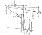
- FIG. 8 is a perspective view showing a propulsion device of a ship according to a second embodiment of the present invention.
- FIG. 9 is a front view showing the propulsion device of the ship according to a second embodiment of the present invention.
- FIG. 10 is a side view showing the propulsion device of the ship according to a second embodiment of the present invention.
- FIG. 11 is an exemplary view showing a duct of a propulsion device according to a second embodiment of the present invention.
- FIG. 12 is a graph showing a change in efficiency according to the inclination ratio (B / H) of the sub-blade according to the second embodiment of the present invention as a curve.
- FIG. 13 is a graph illustrating a change in efficiency according to a radius ratio A / C of a sub blade according to the second exemplary embodiment of the present invention.
- FIG. 15 is a perspective view showing a propulsion device of a ship according to a comparative example compared with the propulsion device shown in FIG. 8 to compare the second distance K distribution.
- FIG. 15 is a perspective view showing a propulsion device of a ship according to a comparative example compared with the propulsion device shown in FIG. 8 to compare the second distance K distribution.
- FIG. 16 is a graph showing a bollard power-thrust between the propulsion device of FIG. 8 and the propulsion device of FIG. 15.
- FIG. 17 is a graph showing respective propulsion performance characteristic curves obtained by a water tank test in order to compare and verify the performance between the propulsion device of FIG. 8 and the propulsion device of FIG. 15.
- FIG. 18 is an exemplary view showing a duct of a propulsion device according to a third embodiment of the present invention.
- the comparative example of one embodiment of the present invention is a standard airfoil, a marin 19A airfoil (hereinafter referred to as a comparative example) generally adopted due to its excellent workability in a duct of the same type as a duct type azimuth thrust. Is).
- FIG. 1 is an exemplary view showing a duct of a propulsion device according to a first embodiment of the present invention
- Figure 2 is a view showing a streamline distribution according to the two-dimensional computational fluid analysis (CFD) results of the duct shown in FIG. .
- CFD computational fluid analysis
- the propulsion apparatus includes a hub 200 receiving power from a gear case and a rotating shaft on a hull side, and a plurality of blades arranged along a circumferential surface of the hub 200.
- a hub 200 receiving power from a gear case and a rotating shaft on a hull side, and a plurality of blades arranged along a circumferential surface of the hub 200.
- the propeller 300 may include a ring-shaped duct (100).
- the cross-sectional shape of the duct 100 may have the same cross-sectional shape along the entire circumference of the duct 100 based on the rotation axis (X axis) of the propeller 300.
- the cross-sectional shape of the duct 100 may improve the efficiency of the duct-type propulsion device in consideration of all of the operating characteristics of the vessel, such as drill ships or offshore structures, the position control characteristics of the vessel and the towing characteristics of other vessels trapped in the ice. It may include the outer surface (G1) and the inner surface (G2) of the duct 100 having a design factor optimized to be.
- the cross-sectional shape of the duct 100 is lifted according to Bernoulli's theorem, so that the airfoil cross section is a nose 104 (nose) which is the front vertex of the airfoil cross section of the duct 100; Tail 108, which is the rear vertex of the airfoil section; And an abdominal line 105 that is a straight line connecting the nose 104 and the tail 108.
- nose 104 nose
- Tail 108 which is the rear vertex of the airfoil section
- abdominal line 105 that is a straight line connecting the nose 104 and the tail 108.
- Cross-sectional shape of the duct 100 is the front portion 113 is formed convexly above the front end of the chord line 105; And an outer surface G1 of the duct 100 having a rear portion 112 that is formed concave below the trailing end 105.
- the front portion 113 of the outer surface (G1) of the duct 100 may mean a curved surface from the point where the chord line 105 meets the outer surface (G1) of the duct 100 to the nose (104).
- the rear portion 112 of the outer surface (G1) of the duct 100 may mean a curved surface from the point where the chord line 105 meets the outer surface (G1) of the duct 100 to the tail (108).
- the front portion 113 and the rear portion 112 may be naturally transitioned before and after the point where the sag line 105 meets the outer surface G1 of the duct 100.
- the front portion 113 of the outer surface G1 of the duct 100 is convexly formed above the front end of the chord line 105.
- the rear portion 112 of the outer surface G1 of the duct 100 is concavely formed below the rear end of the chord line 105.
- the cross-sectional shape of the duct 100 may have an angle of attack ⁇ that is an angle formed by the axis of rotation (X-axis) of the propeller 300 and the chord line 105.
- the angle of attack ⁇ of the duct 100 may have any one angle selected from 5 ° to 20 °.
- the cross-sectional shape of the duct 100 is parallel to the axis of rotation (X axis) of the propeller 300 parallel 111; In the range corresponding to the first distance F in the Y-axis direction from the parallel portion 111 to the nose 104, a curved surface projecting gently from the starting point 109 of the parallel portion 111 to the nose 104.
- It may include the inner surface (G2) of the duct 100 consisting of the duct inner surface rear portion 107 which is a curved surface protruding gently to 108.
- the parallel portion 111 is the front region M and the rear region N of the parallel portion 111 with respect to the propeller surface (YZ plane) position 103 which is a circular surface drawn when the propeller 300 rotates.
- the% range for the electric field (C) to maximize thrust performance based on the results of three-dimensional computational fluid analysis (CFD) (M) / C, N / C).
- FIG. 3 is a graph showing a change in propeller efficiency according to the range of the front region and the rear region of the parallel to the electric field based on the propeller face position in the duct shown in FIG. 1.
- a duct 100 in a bollard condition in which a position control characteristic and a towing characteristic of a ship equipped with the propeller 10 using a three-dimensional computational fluid analysis (CFD) is known.
- the range N / C (many graphs inside the graph) of the front region N of the parallel portion 111 is shown.
- the propeller efficiency ( ⁇ 0 , Merit coefficient) is obtained by using Equation 1 below considering the performance under towing and position control conditions as an important design condition, such as a duct propeller and an azimuth propeller. Can be.
- the conditions of the propeller diameter, the propeller rotation speed, and the density of the fluid (for example, fresh water) and the position control conditions are taken into consideration.
- ⁇ 0 ((K TT / ⁇ ) 3/2 ) / K Q
- K TT K T-propeller + K T-duct
- K Q Q / ( ⁇ * n 2 * D P 5 )
- Equation 1 ⁇ 0 is the propeller efficiency (Merit coefficient), T P is the propeller thrust, T D is the duct thrust, Q is the propeller torque, D P is the propeller diameter, n is the propeller rotation speed , ⁇ is the density of the fluid (eg fresh water).
- the cross-sectional shape of the duct 100 of the present embodiment is a parallel portion having a range (M / C) of -4.0% to 14.0% of the full length C from the propeller face position 103.
- Front region M of 111 and rear region N of parallel portion 111 having a range (N / C) of -30.0% to -10.0% relative to full length C from propeller face position 103. can do.
- the-value means the-direction when the propeller plane position 103 is set as the origin in the x-axis direction.
- the M / C value is -4.0%, it means that the starting point 109 of the parallel part is separated from the propeller face position 103 by 4% of the length C of the full length C to the right side of FIG.
- the reference point of +/- in the x-axis direction is the propeller plane position 103, so that even if the installation position of the duct 100 or the installation position of the propeller is changed even in the same duct shape, the position of the reference point is also changed. This changes the values of M / C and N / C and changes the efficiency.
- the parallel portion 111 adjacent to the propeller 300 must maintain a constant length to improve efficiency. Therefore, the M / C value of the front region M of the parallel portion 111 relative to the full length C is less than -4.0%, or the N / C of the rear region N of the parallel portion 111 relative to the full length C. When the value exceeds -10.0%, the length of the parallel part 111 is narrow, so that the efficiency improvement effect may be insignificant.
- the first distance F between the parallel portion 111 and the nose 104 and the second distance K between the parallel portion 111 and the tail 108 are operated by the ship.
- % range compared to the electric field (C) that can maximize thrust performance based on the results of three-dimensional computational fluid analysis (CFD). / C).
- FIG. 4 shows a trend of change in propeller efficiency according to the electric field contrast range for the first distance between the parallel portion and the nose and the electric field contrast range for the second distance between the parallel portion and the tail in the duct shown in FIG. It is a graph.
- the graph longitudinal axis of FIG. 4 shows the propeller efficiency ⁇ 0 (Merit coefficient) (graph longitudinal axis) under bollard conditions.
- the graph abscissa of FIG. 4 shows and% range (F / C) with respect to full length C with respect to 1st distance F.
- the% range K / C versus the total length C for the second distance K is shown.
- the cross-sectional shape of the duct 100 of the present embodiment is 18.0% to 30.0% of the total length C from the parallel portion 111 to the nose 104 in the range (F / C). It may include one distance (F) and the second distance (K) in the range (K / C) of 4.0% ⁇ 10.0% of the total length (C) from the parallel portion 111 to the tail 108.
- FIG. 5 is a graph showing a bollard (Bollard) performance curve (Power-thrust) between the duct and the comparative example shown in FIG.
- the airfoil cross section of the duct described above was used, and for comparison of Bollard performance, a marine 19A airfoil was used as a comparative example.
- the Bollard (Power-thrust) for each airfoil cross section according to the present embodiment and the comparative example can be obtained through a model test (bath test).
- FIG. 6 is a graph showing a correlation curve between ship speed and required horsepower between the duct and the comparative example shown in FIG. 1.
- the present embodiment compared to the same horsepower required (DHP) can be faster than the comparative example, or compared to the same speed compared to the comparative example, it can be seen that the performance improvement was achieved by requiring a smaller horsepower.
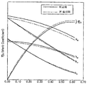
- FIG. 7 is a graph showing respective propulsion performance characteristic curves obtained by a water tank test in order to compare and verify the performance of the duct shown in FIG. 1 and the comparative example.
- the graph abscissa represents the change trend for the propeller forward ratio J
- the graph ordinate represents the thrust Kt, the torque 10Kq, and the efficiency ⁇ O.
- the duct of this example has reduced torque (10Kq) in all the forward coefficient (J) regions compared to the 19A airfoil of the comparative example.
- FIG 8 is a perspective view showing a propulsion device of a ship according to a second embodiment of the present invention
- Figure 9 is a front view showing a propulsion device of a ship according to a second embodiment of the present invention
- Figure 10 is a second view of the present invention
- Figure 11 is an exemplary view showing a duct of the propulsion device according to a second embodiment of the present invention.
- the propulsion apparatus includes a hub 200 receiving power from a main shaft (not shown) of the hull, and a main blade installed on a circumferential surface of the hub 200.
- the propeller 300 including the 310 and the sub blade 320 and a duct 100 installed to surround the propeller 300 may be included.
- the hub 200 is coupled to the gear case 10 in which the main shaft of the hull is built so as to be rotatable by the main shaft, the propeller 300 receives the power of the main engine (not shown) of the hull through the main shaft. Can provide thrust.
- Hub 200 may be formed in the form of a taper (taper) is gradually reduced in radius toward the rear of the propulsion device, the cap 210 may be coupled to the rear end of the hub (200). Cap 210 is tapered toward the rear, it is possible to smoothly flow the fluid passing through the propeller 300 along the side of the cap.
- taper taper
- Cap 210 is tapered toward the rear, it is possible to smoothly flow the fluid passing through the propeller 300 along the side of the cap.
- the outer circumferential surface of the hub 200 may be provided with a propeller 300 that can effectively reduce the vortex (W) is induced around the hub (200).
- the propeller 300 may include a main blade 310 and a sub blade 320 spaced apart from each other along the axial direction (X direction) of the main shaft on the outer surface of the hub 200.
- the main blade 310 may be a plurality of wings arranged radially spaced apart from the front outer peripheral surface of the hub (200).
- the main blade 310 may have a airfoil cross section, and the shape and number of the main blades 310 may be variously changed according to propeller efficiency, cavitation depending on load, and the surrounding environment.
- the sub blade 320 may be a plurality of wings arranged radially spaced apart from the main blade 310 in the rear outer peripheral surface of the hub 200 spaced rearward of the main shaft 310 from the main blade 310. have. However, the sub blade 320 may be installed anywhere, such as the space between the hub 200 and the cap 210 or the hub 200 and the cap 210 if the main blade 310 is spaced rearward from the main shaft 310. Do.
- the sub blade 320 may be formed of a wing having a smaller size than the main blade 310, and the sub blade 320 may be installed to be inclined to the rear of the main shaft.
- the inclination of the rear means that the rear end of the sub blade 320 is located behind the main shaft.
- the sub-blade 320 is capable of absorbing rotational components under low forward ratio conditions, such as a bollard state in which only the propeller rotates at the rated RPM, and thus, absorbs vortices W induced around the hub 200. At the same time, the propulsion efficiency can be improved by reducing the torque of the hub 200.
- the sub blade 320 may have an inclination angle B that is inclined in the range of 0.1 to 27 degrees to the rear of the main axis in the vertical direction of the main axis, and the hub 200 is in the axial direction of the main axis on the outer surface of the hub 200. It may have an inclination angle (H) inclined in the range of 10 to 18 degrees in (-X axis direction).
- FIG. 12 is a graph showing a change in efficiency according to the inclination ratio (B / H) of the sub-blade according to the second embodiment of the present invention as a curve.
- the inclination ratio (B / H) of the sub-blade 320 should be maintained in the range of 0.25 to 1.5 to improve the propeller efficiency.
- the inclination ratio B / H of the sub blade 320 is less than 0.25 or the inclination ratio B / H exceeds 1.5, effectively reducing the vortices W induced around the hub 200 may be reduced. It may be difficult to improve the propeller efficiency.
- the propeller efficiency ( ⁇ 0 , Merit coefficient) is calculated using Equation 1 described above by considering performance under towing and position control conditions as an important design condition, such as a duct propeller and an azimuth propeller. Can be.
- FIG. 13 is a graph illustrating a change in efficiency according to a radius ratio A / C of a sub blade according to the second exemplary embodiment of the present invention.
- the radius ratio (A / C) of the subblade 320 was determined. ) Maintains an upward curve at 0.3, has a maximum propeller efficiency at 0.5, and rapidly decreases after 0.7.
- A may be defined as the radial length of the sub blade 320
- C may be defined as the full length of the duct 100.
- the position E of the sub blade 320 is Excellent performance can be realized when located in the range (E P ⁇ E P + 0.5C) within 0.5C (half of the full length of the duct) from the position E P of the main blade 310 to the rear of the main shaft. can confirm. That is, the axial direction (-X axis direction) position E of the subblade 320 draws a gentle downward curve from the position E P of the main blade to the position E P + 0.5C to the rear of the main axis. When it drops sharply.
- E may be defined as the X-direction position of the sub blade 320
- E P may be defined as the X-direction position of the main blade 320
- C may be defined as the full length of the duct 100. have.
- FIG. 15 is a perspective view showing a propulsion device of a ship according to a comparative example compared to the propulsion device shown in FIG. 8 to compare the second distance K distribution
- FIG. 16 is a propulsion device of FIG. 8 and propulsion of FIG. 15.
- FIG. 17 is a characteristic of each propulsion performance obtained by a water tank test in order to compare and verify the performance between the propulsion device of FIG. 8 and the propulsion device of FIG. 15.
- a marin 19A airfoil, a duct 100 of the same type as a ducted azimuth thrust was used as a comparative example for Bollard performance comparison.
- the Bollard (Power-thrust) for each airfoil cross section according to the present embodiment and the comparative example can be obtained through a model test (bath test).
- the present embodiment in which the sub blade 320 is provided has a bollard condition of about 4.0% compared to the comparative example without the sub blade 320. It can be seen that the thrust in the (bollard condition) is improved.
- the duct 100 of the present embodiment reduced the torque Kq in all the forward coefficients J region compared with the 19A airfoil of the comparative example.
- the present invention provides a main blade and a sub blade in the hub to improve the circumferential flow of the duct and the propeller, to reduce the vortices generated by the propeller, to reduce the torque required to rotate the propeller, and to propel
- the efficiency can be improved, and the thrust under the bollard conditions can be improved to effectively reduce the vortices induced around the hub, and the propulsion efficiency can be improved by reducing the torque of the spindle.
- FIG. 18 is an exemplary view showing a duct of a propulsion device according to a third embodiment of the present invention.
- the duct 100 according to the third embodiment is arranged to align in the axial direction of the main axis and surround the hub 200 based on the axial direction (X axis) of the main axis. It may have the same cross-sectional shape along the entire circumference of the 100.
- the duct 100 is a design factor optimized to improve the efficiency of the duct type propulsion device in consideration of all the operational characteristics of the ship, such as drill ships or offshore structures, the position control characteristics of the vessel and the towing characteristics of other vessels trapped in the ice It may include an outer surface (G1) and the inner surface (G2) of the duct 100 having a.
- the cross-sectional shape of the duct 100 connects the nose 104 which is the front vertex of the airfoil cross section, the tail 108 which is the rear vertex of the airfoil cross section, and connects the nose 104 and the tail 108. It may include a ship line 105 which is a straight line. And the cross-sectional shape of the duct 100 is a duct 100 having a front portion 113 formed convexly above the front end of the chord line 105, and a rear portion 112 formed concave below the rear end of the Hyunseon line 105. It may include the outer surface (G1) of).
- the front portion 113 of the outer surface (G1) of the duct 100 may mean a curved surface from the point where the chord line 105 meets the outer surface (G1) of the duct 100 to the nose (104).
- the rear portion 112 of the outer surface G1 of the duct 100 may mean a curved surface from the point where the chord line 105 meets the outer surface G1 of the duct 100 to the tail 108.
- the front portion 113 and the rear portion 112 may be connected by transitioning before and after the point where the sag line 105 meets the outer surface G1 of the duct 100. In this way, the front portion 113 of the outer surface G1 of the duct 100 is convexly formed above the front end of the chord line 105.
- the front portion of the outer surface of the duct 100 has a convex shape formed convexly above the tip line, the flow flowing into the propeller 300 may be accelerated. Due to this acceleration effect, it is possible to improve the duct 100 thrust and reduce the propeller 300 torque. And since the rear portion 112 of the outer surface (G1) of the duct 100 is formed concave below the rear end of the chord line 105, the flow of the rear outer region flows smoothly in the tail direction of the duct 100, Forming a vortex in the tail can exhibit the effect of improving the duct 100 thrust.
- the cross-sectional shape of the duct 100 is a parallel portion 111 parallel to the axial direction (X axis) of the main axis, and the first distance F in the Y-axis direction from the parallel portion 111 to the nose 104.
- the duct 100 inner surface front portion 106 which is a curved surface projecting gently from the starting point 109 of the parallel portion 111 to the nose 104, is smaller than the first distance F and is parallel.
- 100 may include an inner surface G2 of the duct 100 formed of an inner surface rear portion 107.
- the cross-sectional shape of the duct 100 of the present embodiment is the front region M of the parallel portion 111 having a range (M / C) of -4.0% to 14.0% of the full length C from the propeller face position 103. ) And the rear region N of the parallel portion 111 having a range (N / C) of -30.0% to -10.0% relative to the full length C from the propeller face position 103.
- the efficiency can be improved by maintaining a constant length of the parallel part 111 adjacent to the propeller 300 in the duct 100, M / C which is the front region M of the parallel part 111 compared to the electric field C.
- M / C which is the front region M of the parallel part 111 compared to the electric field C.
- the cross-sectional shape of the duct 100 of this embodiment is parallel to the 1st distance F of 18.0%-30.0% of range (F / C) with respect to the electric field C from the parallel part 111 to the nose 104, and is parallel. From the portion 111 to the tail 108 may include a second distance (K) in the range (K / C) of 4.0% ⁇ 10.0% of the total length (C).
Landscapes
- Chemical & Material Sciences (AREA)
- Engineering & Computer Science (AREA)
- Combustion & Propulsion (AREA)
- Mechanical Engineering (AREA)
- Ocean & Marine Engineering (AREA)
- Structures Of Non-Positive Displacement Pumps (AREA)
- Wind Motors (AREA)
Abstract
Description
Claims (13)
- 익형 단면의 앞쪽 꼭지점인 노즈와, 상기 익형 단면의 뒤쪽 꼭지점인 테일을 갖는 덕트를 포함하고,상기 덕트의 단면 형상은,상기 덕트의 전단에서 상방향으로 볼록하게 형성되고 상기 덕트의 후단에서 하방향으로 오목하게 형성된 외면; 및상기 덕트의 전단에서 하방향으로 볼록하게 형성되는 덕트 내면 전방부와, 상기 덕트의 후단에서 하방향으로 볼록하게 형성되는 덕트 내면 후방부와, 상기 덕트 내면 전방부 및 상기 덕트 내면 후방부를 평행하게 연결하는 평행부를 포함하는 내면을 포함하는 선박의 추진장치.
- 제 1 항에 있어서,상기 외면은상기 노즈와 상기 테일을 연결하는 직선분인 익현선의 전단 위쪽에서 볼록하게 형성된 전방부와, 상기 익현선의 후단 아래쪽에서 오목하게 형성된 후방부를 포함하는 선박의 추진장치.
- 제 1 항에 있어서,상기 덕트 내면 전방부는상기 평행부로부터 상기 노즈까지 Y축 방향의 제 1 거리에 대응한 범위 내에서, 상기 평행부의 시작점으로부터 상기 노즈까지 곡면이고,상기 덕트 내면 후방부는상기 제 1 거리에 비해 작되 상기 평행부로부터 상기 테일까지 Y축 방향의 제 2 거리에 대응한 범위 내에서, 상기 평행부의 끝점으로부터 상기 테일까지 곡면인 선박의 추진장치.
- 제 1 항에 있어서,상기 평행부는,상기 프로펠러가 회전할 때 그리는 원형면인 프로펠러 면 위치로부터 전장 대비 -4.0% ~ 14.0% 범위를 갖는 상기 평행부의 전방영역; 및상기 프로펠러 면 위치로부터 전장 대비 -30.0% ~ -10.0% 범위를 갖는 상기 평행부의 후방영역을 포함하는 선박의 추진장치.
- 제 3 항에 있어서,상기 덕트의 단면 형상은,상기 평행부로부터 상기 노즈까지 전장 대비 18.0% ~ 30.0% 범위의 상기 제 1 거리; 및상기 평행부로부터 상기 테일까지 전장 대비 4.0% ~ 10.0% 범위의 상기 제 2 거리를 포함하는 선박의 추진장치.
- 제 1 항에 있어서,상기 덕트는,하기의 수학식에 의해 구해지는 추진기 효율을 갖는 것을 특징으로 하는 선박의 추진장치.(수학식)η0=((KTT/π)3/2)/KQ여기서, KTT=KT-propeller+KT-duct이고,KT-propeller=TP/(ρ*n2*DP 4)이고,KT-duct=TD/(ρ*n2*DP 4)이고,KQ=Q/(ρ*n2*DP 5)임.상기 수학식에서, η0는 추진기 효율(Merit coefficient), TP는 프로펠러 추력이고, TD는 덕트 추력이고, Q는 프로펠러 토크이고, DP는 프로펠러 직경이고, n은 프로펠러 회전수이고, ρ는 유체의 밀도임.
- 동력을 전달받는 주축 상에 배치되는 허브;상기 허브의 외주면에 설치되는 메인 블레이드;상기 메인 블레이드에서 상기 주축의 후방으로 이격되게 위치되고, 상기 주축의 후방으로 경사지게 설치되는 서브 블레이드; 및상기 메인 블레이드의 둘레에 배치되고, 익형 단면을 갖는 덕트를 포함하는 선박의 추진장치.
- 제 7 항에 있어서,상기 메인 블레이드는 상기 허브의 외주면을 따라 이격 배치되는 다수개로 제공되고,상기 서브 블레이드는 상기 메인 블레이드와 교호로 배치되는 다수개로 제공되는 선박의 추진장치.
- 제 7 항에 있어서,상기 서브 블레이드는 상기 주축의 수직 방향에서 상기 주축의 후방으로 0.1~27도 범위로 기울어지는 기울임 각도(B)를 갖는 선박의 추진장치.
- 제 9 항에 있어서,상기 서브 블레이드의 경사비(B/H)는 0.25 ~ 1.5 범위를 만족하는 선박의 추진장치.상기 경사비(B/H)에서, B는 주축의 수직 방향(Y축 방향)에서 주축의 후방으로 기울어진 서브 블레이드의 기울임 각도이고, H는 허브 외면에서 주축의 축 방향으로 기울어진 허브 외면의 기울임 각도임.
- 제 7 항에 있어서,상기 서브 블레이드의 반경비(A/C)는 0.3 ~ 0.7 범위를 만족하는 선박의 추진장치.상기 반경비(A/C)에서, A는 서브 블레이드의 반경 길이이고, C는 덕트의 전장 길이임.
- 제 7 항에 있어서,상기 서브 블레이드는상기 메인 블레이드의 위치에서 상기 주축의 후방으로 덕트 전장 길이 대비 0.5 길이까지의 범위 내에 위치되는 선박의 추진장치.
- 제 7 항에 있어서,상기 덕트는 익형 단면의 앞쪽 꼭지점인 노즈와, 상기 익형 단면의 뒤쪽 꼭지점인 테일을 포함하고,상기 덕트의 단면 형상은,상기 덕트의 전단에서 상방향으로 볼록하게 형성되고 상기 덕트의 후단에서 하방향으로 오목하게 형성된 외면; 및상기 덕트의 전단에서 하방향으로 볼록하게 형성되는 덕트 내면 전방부와, 상기 덕트의 후단에서 하방향으로 볼록하게 형성되는 덕트 내면 후방부와, 상기 덕트 내면 전방부 및 상기 덕트 내면 후방부를 평행하게 연결하는 평행부를 포함하는 내면을 포함하는 선박의 추진장치.
Priority Applications (4)
| Application Number | Priority Date | Filing Date | Title |
|---|---|---|---|
| JP2015556876A JP6490595B2 (ja) | 2013-02-08 | 2014-02-10 | 船舶の推進装置 |
| EP14749497.5A EP2955099B1 (en) | 2013-02-08 | 2014-02-10 | Propulsion device for ship |
| CN201480007971.7A CN105026259B (zh) | 2013-02-08 | 2014-02-10 | 用于船舶的推进设备 |
| US14/765,952 US10040528B2 (en) | 2013-02-08 | 2014-02-10 | Propulsion device for ship |
Applications Claiming Priority (6)
| Application Number | Priority Date | Filing Date | Title |
|---|---|---|---|
| KR1020130014232A KR101444293B1 (ko) | 2013-02-08 | 2013-02-08 | 추진 장치용 덕트 |
| KR10-2013-0014232 | 2013-02-08 | ||
| KR1020130115287A KR101523920B1 (ko) | 2013-09-27 | 2013-09-27 | 선박의 추진장치 |
| KR10-2013-0115287 | 2013-09-27 | ||
| KR1020140014302A KR101589124B1 (ko) | 2014-02-07 | 2014-02-07 | 선박의 추진장치 |
| KR10-2014-0014302 | 2014-02-07 |
Publications (1)
| Publication Number | Publication Date |
|---|---|
| WO2014123397A1 true WO2014123397A1 (ko) | 2014-08-14 |
Family
ID=51299940
Family Applications (1)
| Application Number | Title | Priority Date | Filing Date |
|---|---|---|---|
| PCT/KR2014/001085 Ceased WO2014123397A1 (ko) | 2013-02-08 | 2014-02-10 | 선박의 추진장치 |
Country Status (5)
| Country | Link |
|---|---|
| US (1) | US10040528B2 (ko) |
| EP (1) | EP2955099B1 (ko) |
| JP (1) | JP6490595B2 (ko) |
| CN (1) | CN105026259B (ko) |
| WO (1) | WO2014123397A1 (ko) |
Families Citing this family (7)
| Publication number | Priority date | Publication date | Assignee | Title |
|---|---|---|---|---|
| CN105366017A (zh) * | 2015-12-04 | 2016-03-02 | 苏州金业船用机械厂 | 一种高性能螺旋桨 |
| JP1562438S (ko) * | 2016-02-19 | 2016-11-07 | ||
| NL2018388B1 (en) * | 2017-02-16 | 2018-09-06 | Veth Propulsion B V | Thruster for propelling a watercraft |
| CN106828849A (zh) * | 2017-02-22 | 2017-06-13 | 哈尔滨工程大学 | 一种应用仿生导管的导管桨 |
| CN107117277A (zh) * | 2017-04-12 | 2017-09-01 | 哈尔滨工程大学 | 带有仿生导管的吊舱推进器 |
| WO2019122464A1 (es) * | 2017-12-20 | 2019-06-27 | Romero Vazquez Juan Jose | Sistema hélice tobera aceleradora para impulsar barcos |
| US11353001B1 (en) | 2021-04-30 | 2022-06-07 | Sitkana Inc. | Hydrokinetic generator |
Citations (6)
| Publication number | Priority date | Publication date | Assignee | Title |
|---|---|---|---|---|
| JPH02151593A (ja) * | 1988-12-01 | 1990-06-11 | Grausring Joship | 船の推進装置 |
| KR910700173A (ko) * | 1989-01-20 | 1991-03-14 | 가메다까 소끼찌 | 선박용 추진장치 |
| KR20000018734U (ko) * | 1999-03-26 | 2000-10-25 | 김형벽 | 프로펠러 보스캡 부착형 보조 프로펠러 |
| JP2001516675A (ja) * | 1997-09-15 | 2001-10-02 | エービービー アジポド オイ | 推進システム及び方法 |
| JP2006306304A (ja) * | 2005-04-28 | 2006-11-09 | Niigata Shipbuilding & Repair Inc | 推進装置及びその製造方法 |
| KR20120098941A (ko) | 2010-02-16 | 2012-09-05 | 카와사키 주코교 카부시키 카이샤 | 덕트 부착 스러스터 및 이를 구비한 선박 |
Family Cites Families (18)
| Publication number | Priority date | Publication date | Assignee | Title |
|---|---|---|---|---|
| US1363660A (en) * | 1916-11-07 | 1920-12-28 | Fleur Essaie La | Propeller |
| GB189158A (en) * | 1921-05-25 | 1922-11-27 | Conrad Vaughan Treleaven | An improved construction of screw propeller |
| US1944525A (en) * | 1932-03-28 | 1934-01-23 | Luis Medina Y Pereyra | Twin propeller |
| JPS5131489A (en) * | 1974-09-12 | 1976-03-17 | Akashi Funegata Kenkyusho Kk | Dakuto puropera |
| FI79991C (fi) * | 1986-04-29 | 1990-04-10 | Hollming Oy | Propelleranordning foer ett fartyg. |
| US5799394A (en) * | 1996-02-05 | 1998-09-01 | Rice; Jose Luis | Method of making a marine speed nozzle |
| RU2115589C1 (ru) * | 1996-06-25 | 1998-07-20 | Государственный научно-исследовательский и проектно-конструкторский институт по развитию и эксплуатации флота "Гипрорыбфлот" | Судовая движительно-двигательная установка типа "поворотная колонка" |
| RU2115588C1 (ru) * | 1996-06-25 | 1998-07-20 | Государственный научно-исследовательский и проектно-конструкторский институт по развитию и эксплуатации флота "Гипрорыбфлот" | Судовая движительно-двигательная установка типа "поворотная колонка" |
| US5766047A (en) * | 1996-09-25 | 1998-06-16 | Brunswick Corporation | Twin propeller marine propulsion unit |
| KR20000018734A (ko) | 1998-09-04 | 2000-04-06 | 윤종용 | 반도체 소자의 고밀도 플라즈마 절연막 형성방법 |
| GB0526182D0 (en) * | 2005-12-22 | 2006-02-01 | Watts Alan E | Propeller |
| JP5405872B2 (ja) | 2009-03-30 | 2014-02-05 | 株式会社三井造船昭島研究所 | 船舶の推進装置とそれを備えた船舶 |
| DE102010052248A1 (de) | 2010-11-23 | 2012-05-24 | Voith Patent Gmbh | Schiffsantrieb mit einer Düse und einem Propeller |
| FI122660B (fi) * | 2010-12-30 | 2012-05-15 | Waertsilae Finland Oy | Sisäänvedettävä vesialuksen ohjauspotkuriyksikkö |
| KR20120100267A (ko) * | 2011-03-03 | 2012-09-12 | 삼성중공업 주식회사 | 아지무스 스러스터 및 이를 구비한 선박 |
| KR101313616B1 (ko) * | 2011-06-15 | 2013-10-02 | 삼성중공업 주식회사 | 선박용 추진장치 및 이를 포함하는 선박 |
| CN202368778U (zh) * | 2011-12-12 | 2012-08-08 | 江苏华海船舶设计有限公司 | 组合节能运输船舶 |
| KR101350514B1 (ko) * | 2012-02-03 | 2014-01-10 | 삼성중공업 주식회사 | 초전도 베어링을 구비한 이중 반전 프로펠러식 추진장치 및 이를 구비한 선박 |
-
2014
- 2014-02-10 CN CN201480007971.7A patent/CN105026259B/zh active Active
- 2014-02-10 US US14/765,952 patent/US10040528B2/en active Active
- 2014-02-10 JP JP2015556876A patent/JP6490595B2/ja active Active
- 2014-02-10 EP EP14749497.5A patent/EP2955099B1/en active Active
- 2014-02-10 WO PCT/KR2014/001085 patent/WO2014123397A1/ko not_active Ceased
Patent Citations (6)
| Publication number | Priority date | Publication date | Assignee | Title |
|---|---|---|---|---|
| JPH02151593A (ja) * | 1988-12-01 | 1990-06-11 | Grausring Joship | 船の推進装置 |
| KR910700173A (ko) * | 1989-01-20 | 1991-03-14 | 가메다까 소끼찌 | 선박용 추진장치 |
| JP2001516675A (ja) * | 1997-09-15 | 2001-10-02 | エービービー アジポド オイ | 推進システム及び方法 |
| KR20000018734U (ko) * | 1999-03-26 | 2000-10-25 | 김형벽 | 프로펠러 보스캡 부착형 보조 프로펠러 |
| JP2006306304A (ja) * | 2005-04-28 | 2006-11-09 | Niigata Shipbuilding & Repair Inc | 推進装置及びその製造方法 |
| KR20120098941A (ko) | 2010-02-16 | 2012-09-05 | 카와사키 주코교 카부시키 카이샤 | 덕트 부착 스러스터 및 이를 구비한 선박 |
Also Published As
| Publication number | Publication date |
|---|---|
| US10040528B2 (en) | 2018-08-07 |
| EP2955099A4 (en) | 2016-09-28 |
| CN105026259B (zh) | 2018-11-27 |
| JP6490595B2 (ja) | 2019-03-27 |
| CN105026259A (zh) | 2015-11-04 |
| JP2016506892A (ja) | 2016-03-07 |
| EP2955099A1 (en) | 2015-12-16 |
| US20150360760A1 (en) | 2015-12-17 |
| EP2955099B1 (en) | 2018-08-29 |
Similar Documents
| Publication | Publication Date | Title |
|---|---|---|
| WO2014123397A1 (ko) | 선박의 추진장치 | |
| KR102033030B1 (ko) | 풍력추진 기능이 구비된 선박 | |
| US20100310357A1 (en) | Ring wing-type actinic fluid drive | |
| WO2014003427A1 (ko) | 함체의 추진 및 방향전환장치 | |
| US8403716B2 (en) | Twin-skeg ship | |
| WO2010140831A2 (ko) | 선박 추진장치 | |
| US6427618B1 (en) | Bow mounted system and method for jet-propelling a submarine or torpedo through water | |
| KR20120124205A (ko) | 연료절감형 선박용 크라운 덕트 | |
| CN106043641A (zh) | 一种船用环形导流栅 | |
| CN105209337A (zh) | 推力发生装置 | |
| KR20120068158A (ko) | 선박용 틸팅덕트 구조체 | |
| KR101516839B1 (ko) | 선박용 덕트 구조체 | |
| WO2012091272A1 (ko) | 선박 추진장치 | |
| KR20180048769A (ko) | 선미 덕트를 가진 선미 형상 및 선박 | |
| KR101962796B1 (ko) | 풍력추진 기능이 구비된 선박 | |
| JP6548062B2 (ja) | 船尾用ダクト、船尾用付加物、船尾用ダクトの設計方法、及び船尾用ダクトを装備した船舶 | |
| EP2500260A1 (en) | Propulsion device for ship | |
| WO2019194350A1 (ko) | 선박용 프로펠러 | |
| EP0867361A2 (en) | Nautical propulsor with ducted rotor propeller | |
| KR101523920B1 (ko) | 선박의 추진장치 | |
| WO2017119630A1 (ko) | 고속 후방 분사 및 일체 회전 방식의 선박용 추진 장치 | |
| KR101589124B1 (ko) | 선박의 추진장치 | |
| KR20240013002A (ko) | 선박용 가속 프로펠러 | |
| WO2019245088A1 (ko) | 선박용 추진장치 | |
| WO2019027126A1 (ko) | 덕트형 선박 에너지 절감 장치 |
Legal Events
| Date | Code | Title | Description |
|---|---|---|---|
| WWE | Wipo information: entry into national phase |
Ref document number: 201480007971.7 Country of ref document: CN |
|
| WWE | Wipo information: entry into national phase |
Ref document number: 2014749497 Country of ref document: EP |
|
| ENP | Entry into the national phase |
Ref document number: 2015556876 Country of ref document: JP Kind code of ref document: A |
|
| 121 | Ep: the epo has been informed by wipo that ep was designated in this application |
Ref document number: 14749497 Country of ref document: EP Kind code of ref document: A1 |
|
| WWE | Wipo information: entry into national phase |
Ref document number: 14765952 Country of ref document: US |
|
| NENP | Non-entry into the national phase |
Ref country code: DE |