WO2014125545A1 - 管接続用ねじ継手 - Google Patents
管接続用ねじ継手 Download PDFInfo
- Publication number
- WO2014125545A1 WO2014125545A1 PCT/JP2013/007431 JP2013007431W WO2014125545A1 WO 2014125545 A1 WO2014125545 A1 WO 2014125545A1 JP 2013007431 W JP2013007431 W JP 2013007431W WO 2014125545 A1 WO2014125545 A1 WO 2014125545A1
- Authority
- WO
- WIPO (PCT)
- Prior art keywords
- pin
- box
- female screw
- pipe
- seal
- Prior art date
- Legal status (The legal status is an assumption and is not a legal conclusion. Google has not performed a legal analysis and makes no representation as to the accuracy of the status listed.)
- Ceased
Links
Images


Classifications
-
- F—MECHANICAL ENGINEERING; LIGHTING; HEATING; WEAPONS; BLASTING
- F16—ENGINEERING ELEMENTS AND UNITS; GENERAL MEASURES FOR PRODUCING AND MAINTAINING EFFECTIVE FUNCTIONING OF MACHINES OR INSTALLATIONS; THERMAL INSULATION IN GENERAL
- F16L—PIPES; JOINTS OR FITTINGS FOR PIPES; SUPPORTS FOR PIPES, CABLES OR PROTECTIVE TUBING; MEANS FOR THERMAL INSULATION IN GENERAL
- F16L15/00—Screw-threaded joints; Forms of screw-threads for such joints
- F16L15/06—Screw-threaded joints; Forms of screw-threads for such joints characterised by the shape of the screw-thread
-
- E—FIXED CONSTRUCTIONS
- E21—EARTH OR ROCK DRILLING; MINING
- E21B—EARTH OR ROCK DRILLING; OBTAINING OIL, GAS, WATER, SOLUBLE OR MELTABLE MATERIALS OR A SLURRY OF MINERALS FROM WELLS
- E21B17/00—Drilling rods or pipes; Flexible drill strings; Kellies; Drill collars; Sucker rods; Cables; Casings; Tubings
- E21B17/02—Couplings; joints
- E21B17/04—Couplings; joints between rod or the like and bit or between rod and rod or the like
- E21B17/042—Threaded
-
- F—MECHANICAL ENGINEERING; LIGHTING; HEATING; WEAPONS; BLASTING
- F16—ENGINEERING ELEMENTS AND UNITS; GENERAL MEASURES FOR PRODUCING AND MAINTAINING EFFECTIVE FUNCTIONING OF MACHINES OR INSTALLATIONS; THERMAL INSULATION IN GENERAL
- F16L—PIPES; JOINTS OR FITTINGS FOR PIPES; SUPPORTS FOR PIPES, CABLES OR PROTECTIVE TUBING; MEANS FOR THERMAL INSULATION IN GENERAL
- F16L15/00—Screw-threaded joints; Forms of screw-threads for such joints
- F16L15/001—Screw-threaded joints; Forms of screw-threads for such joints with conical threads
- F16L15/004—Screw-threaded joints; Forms of screw-threads for such joints with conical threads with axial sealings having at least one plastically deformable sealing surface
Definitions
- the present invention relates to a threaded joint for pipe connection (threaded joint for pipe).
- oil well pipes including tubing and casings commonly used for exploration and production of oil wells and gas wells, that is, OCTG (oil county tubular goods), riser tubes ( riser pipe) and threaded joints for connecting pipes such as linepipes, especially sealability, compression resistance and galling resistance
- OCTG oil county tubular goods
- riser tubes riser pipe
- threaded joints for connecting pipes such as linepipes, especially sealability, compression resistance and galling resistance
- the present invention relates to an excellent threaded joint for pipe connection.
- Threaded joints are widely used for connecting steel pipes (hereinafter also referred to as pipes) used in oil production equipment such as oil well pipes.
- pipes steel pipes
- API American Petroleum Institute
- standard threaded joints specified in the API (American Petroleum Institute) standard have been typically used to connect steel pipes used for oil and gas exploration and production.
- API American Petroleum Institute
- vertical wells, horizontal wells, directional wells, etc. are increasing. For this reason, the drilling and production environment has become severe.
- due to the increasing development of wells in poor environments such as the ocean and polar regions, compression resistance, bending resistance, seal performance of external pressure, etc.
- the required performance for threaded joints is diversified.
- Premium joints typically include a tapered thread, a metal to metal seal, and a torque shoulder on each pipe.
- the taper screw is important for fixing the pipe joint tightly, and the metal touch seal part forms the female side (box component) and the male side (mail side) of the screw joint. Sealing performance is ensured by metal contact with the pin component, and the torque shoulder portion serves as a shoulder surface serving as a stopper during tightening of the joint.
- 3 to 5 are schematic explanatory views of a conventional coupling type oil joint pipe premium joint, which is a longitudinal sectional view of a threaded joint of a circular pipe.
- the threaded joint includes a pin 3 which is a male member and a box 1 which is a female member corresponding thereto.
- the pin 3 has a male screw portion 7 on its outer surface and a nose 8 which is a screwless portion provided adjacent to the male screw portion 7 at the tip of the pin 3.
- the nose 8 has a metal touch seal portion (also referred to as a pin seal portion) 11 on its outer peripheral surface and a torque shoulder portion (also referred to as a pin shoulder portion) 12 on its end surface.
- the opposing box 1 is a female screw that is a part that can be screwed together or contacted with the male threaded portion 7, the metal touch seal portion 11, and the torque shoulder portion 12 of the pin 3.
- Patent Document 1 there has been presented a means for suppressing the deformation of the pin seal portion, but there has been no suggestion of a method for solving the above-mentioned problem associated with the deformation on the box side, and there has been a problem in this respect.
- the object of the present invention is to solve the above-mentioned problems, and to provide a threaded joint for pipe connection that hardly causes plastic deformation on the box side even when a repeated tensile-compression load is applied to the pipe, and also has excellent galling resistance. It is to provide.
- a pin having a nose at the tip of the male screw portion, a female screw portion screwed into the male screw portion of the pin, and a box having a nose portion facing the nose of the pin, and located on the nose tip surface of the pin
- the pin shoulder portion is in axial contact with the box shoulder portion, which is the shoulder portion of the box opposite to the pin shoulder portion, and the nose outer peripheral surface of the pin is configured by a convex curve, and the box is opposed to the convex curved surface.
- the female screw on the box side of the angle theta sb forming insert surface with respect to a plane perpendicular to the tube axis (axis of pipe), the insertion surface the tube axis perpendicular of the pin side of the male thread opposite to the insertion face of the female screw Relationship angle theta sp which makes with the plane, 0.05 ° ⁇ ⁇ sb - ⁇ sp ⁇ 2.0 ° pipe connecting screw joint and satisfies the.
- Rlf which is a curvature radius R of a corner connecting a plane of loading of the female screw on the box side and a bottom surface of the female screw is 0.5 mm or more and 1.5 mm or less.
- Rsf which is a radius of curvature R of a corner connecting between the insertion surface of the female screw portion on the box side and the bottom surface of the female screw, is 0.5 mm or more and 1.5 mm or less, (1) or A threaded joint for pipe connection according to (2).
- the convex curved surface that includes the pin seal portion is an arc shape in cross-section observation in the tube axis direction, as described in any one of (1) to (3), Threaded joint for pipe connection.
- the seal taper angle ⁇ seal which is an angle with respect to the tube axis of the taper including the box seal portion is 2 degrees or more and 15 degrees or less, wherein (1) to (4) The threaded joint for pipe connection as described in any one. (6) The threaded joint for pipe connection according to (5), wherein the seal taper angle ⁇ seal is 2 degrees or more and 5 degrees or less.
- FIG. 4 is a cross-sectional view in the tube axis direction around the nose of FIG. 3.
- FIG. 4 is a sectional view in the tube axis direction around a threaded portion of the male screw and the female screw in FIG. 3.
- FIG. 1 and FIG. 2 are sectional views in the tube axis direction showing an example of the embodiment of the present invention.
- FIG. 1 shows the vicinity of the threaded portion of the male screw and the female screw
- FIG. 2 shows the periphery of the nose.
- 20 is a male screw insertion surface on the pin side
- 21 is a female screw insertion surface on the box side
- 22 is a bottom surface of the female screw on the box side
- 23 is a load surface of the male screw on the pin side
- 24 is a box side.
- the same reference numerals are given to the same or corresponding parts as in the previous drawings, and the description thereof is omitted. As shown in FIGS.
- the threaded joint for pipe connection includes a pin 3 having a nose 8 at the tip of a male screw portion 7, and a female screw portion 5 that is screwed with the male screw portion 7 of the pin 3.
- a box 1 having a nose portion facing the nose 8 of the pin 3, and a pin shoulder portion 14 which is a shoulder portion of the box 1 facing the pin shoulder portion 12 located at the nose tip surface of the pin 3; Abutting in the axial direction, the nose outer peripheral surface of the pin 3 is constituted by a convex curved surface, the inner surface of the box 1 facing the convex curved surface is constituted by a taper, the pin seal portion 11 in the convex curved surface and the inside of the taper It is assumed that both the box seal portion 13 and the box seal portion 13 have a structure in which the fluid is sealed by metal contact in the radial direction.
- the strain that accompanies plastic deformation is the most accumulated at the corner connecting the load surface 24 of the internal thread on the box 1 side and the bottom surface 22 of the internal thread. It is a corner portion formed by the insertion surface 21 of the female screw portion on the side of the box 1 and the bottom surface 22 of the female screw. Reducing the strain at these locations is important for preventing abnormal deformation or breakage when laying pipes in diagonal wells and horizontal wells.
- the angle ⁇ sb formed by the female screw insertion surface 21 on the box 1 side with respect to the surface perpendicular to the tube axis and the male screw insertion surface 20 on the pin 3 side opposite thereto are as follows.
- the angle ⁇ sp to the plane perpendicular to the tube axis to 0.05 degrees ⁇ ⁇ sb ⁇ sp , the female screw portion 5 on the box 1 side and the male screw on the pin 3 side when a compression load is applied.
- the convex curved surface containing a pin seal part is circular arc shape (arc shape which has a string inside pin 1) in the cross-sectional view of a pipe-axis direction from a viewpoint of the ease of a screw cutting process.
- Rlf which is the radius of curvature R of the corner portion connecting the load surface 24 of the internal thread on the box 1 side and the bottom surface 22 of the internal thread, is more effective for preventing strain accumulation.
- Rlf is preferably 0.5 mm or more and 1.5 mm or less. More preferably, it is 0.6 mm or more and 1.1 mm or less.
- Rsf which is the radius of curvature R of the corner portion connecting the female screw insertion surface 21 and the female screw bottom surface 22 on the box 1 side, and is preferably 0.5 mm or more and 1.5 mm or less. More preferably, it is 0.6 mm or more and 1.1 mm or less.
- the sealing structure itself is preferably a substantially radial sealing structure.
- the seal taper angle ⁇ seal which is an angle with respect to the tube axis of the taper including the box seal portion 13 is preferably 15 degrees or less, more preferably 5 degrees or less.
- ⁇ seal is preferably 2 degrees or more.
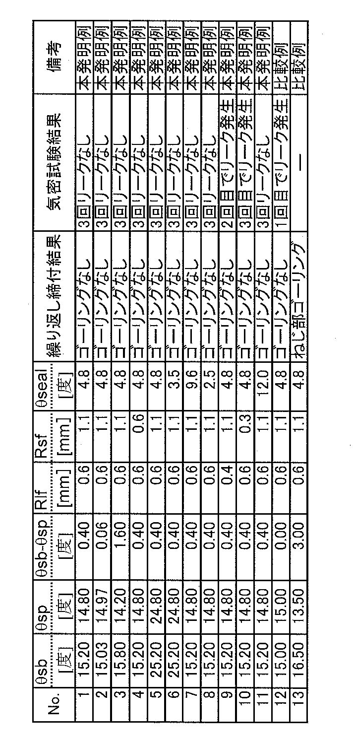
- Table 1 Were manufactured under various shape conditions shown in Table 1, and these were subjected to 10 repeated tightening tests.
- the airtightness test A test (sealability leak test A or tightness leak test A) prescribed in ISO 13679 was repeated three times at maximum.
Landscapes
- Engineering & Computer Science (AREA)
- General Engineering & Computer Science (AREA)
- Mechanical Engineering (AREA)
- Mining & Mineral Resources (AREA)
- Life Sciences & Earth Sciences (AREA)
- Geology (AREA)
- Fluid Mechanics (AREA)
- Environmental & Geological Engineering (AREA)
- Physics & Mathematics (AREA)
- General Life Sciences & Earth Sciences (AREA)
- Geochemistry & Mineralogy (AREA)
- Non-Disconnectible Joints And Screw-Threaded Joints (AREA)
- Gasket Seals (AREA)
Abstract
Description
しかし、近年、原油(crude oil)や天然ガス(natural gas)の井戸は深井戸化が進み、垂直井(vertical well)、水平井(horizontal well)、傾斜井(directional well)等が増えていることから、掘削・生産環境は苛酷化している。また、海洋や極地(polar region)など劣悪な環境での井戸の開発が増加していることなどから、耐圧縮性能、耐曲げ性能(bending resistance)、外圧シール性能(seal performance of external pressure)など、ねじ継手への要求性能は多様化している。そのためプレミアムジョイント(premium joint)と呼ばれる高性能の特殊ねじ継手(threaded joint)を使用することが増加しており、その性能への要求もますます増加している。
プレミアムジョイントは、通常、各パイプに、テーパねじ(tapered thread)と、メタルタッチシール部(metal to metal seal)と、トルクショルダ部(torque shoulder)とを備える。テーパねじは管継手をタイト(tightly)に固定するために重要であり、メタルタッチシール部はねじ継手の雌側(female side)をなすボックス部材(box component)と雄側(mail side)をなすピン部材(pin component)とが金属接触することでシール性を確保するものであり、トルクショルダ部は継手の締付け中にストッパ(abutment)の役目を担うショルダ面となる。
図3~図5は、従来のカップリング形式(coupling type)の油井管用プレミアムジョイントの模式的説明図であり、これは、円管のねじ継手の縦断面図となっている。このねじ継手は雄ねじ部材(male member)であるピン3とこれに対応する雌ねじ部材(female member)であるボックス1とを備える。
ピン3は、その外面に、雄ねじ部7と、ピン3先端に雄ねじ部7に隣接して設けられたねじ無し部であるノーズ(nose)8とを有する。ノーズ8は、その外周面にメタルタッチシール部(ピンシール部とも云う)11を、その端面にはトルクショルダ部(ピンショルダ部とも云う)12を有する。
相対するボックス1は、その内面に、それぞれピン3の雄ねじ部7、メタルタッチシール部11、およびトルクショルダ部12と螺合する(screw together)か、または接触することができる部分である、雌ねじ部5、メタルタッチシール部(ボックスシール部とも云う)13、およびトルクショルダ部(ボックスショルダ部とも云う)14を有している。
ところで、井戸へのパイプ敷設は、通常、パイプを回転させながら施工されるが、斜め掘りおよび水平掘りの場合、パイプは途中、曲げられた状態で回転し、その間、パイプには引張-圧縮の力が繰り返し作用する。そこで、圧縮負荷(compression load)に強い構造として、例えば特許文献1では、ピンのシールリップ部(seal lip)の長さを雄ねじ部と雌ねじ部の螺合状態における管軸方向の隙間の140倍以上とすることにより、圧縮時のピンシール部の変形を弾性範囲内(elastic region)に留める構造が提案されている。
本発明の目的は前記課題を解決し、パイプに引張‐圧縮の繰り返し負荷がかかってもボックス側に塑性変形を生じ難く、然も耐ゴーリング性(galling resistance)にも優れる管接続用ねじ継手を提供することにある。
(1) 雄ねじ部の先端にノーズを備えたピンと、該ピンの雄ねじ部と螺合する雌ねじ部および前記ピンのノーズに相対するノーズ部を有するボックスを備え、前記ピンのノーズ先端面に位置するピンショルダ部がこれと相対する前記ボックスのショルダ部であるボックスショルダ部と軸方向に当接し、前記ピンのノーズ外周面が凸曲面(convex curve)で構成され、該凸曲面に相対する前記ボックスの内面がテーパで構成され、前記凸曲面内のピンシール部と前記テーパ内のボックスシール部との双方が半径方向に金属接触して流体をシールする構造を有する管用ねじ継手において、前記ボックス側の雌ねじの挿入面が管軸(axis of pipe)と垂直な面に対してなす角度θsbと、前記雌ねじの挿入面に対向する前記ピン側の雄ねじの挿入面が管軸と垂直な面に対してなす角度θspの関係が、0.05度≦θsb-θsp≦2.0度を満たすことを特徴とする管接続用ねじ継手。
(2) 前記ボックス側の雌ねじの荷重面(plane of loading)と雌ねじの底面との間を結ぶコーナ(corner)の曲率半径RであるRlfが0.5mm以上1.5mm以下であることを特徴とする前記(1)に記載の管接続用ねじ継手。
(3) 前記ボックス側の雌ねじ部の挿入面と雌ねじの底面との間を結ぶコーナの曲率半径RであるRsfが0.5mm以上1.5mm以下であることを特徴とする前記(1)又は(2)に記載の管接続用ねじ継手。
(4) 前記ピンシール部を内包する凸曲面が管軸方向の断面視(cross-section observation)で円弧状であることを特徴とする前記(1)~(3)のいずれか1つに記載の管接続用ねじ継手。
(5) 前記ボックスシール部を内包するテーパの管軸に対する角度であるシールテーパ角度(seal taper angle)θsealが2度以上15度以下であることを特徴とする前記(1)~(4)のいずれか1つに記載の管接続用ねじ継手。
(6) 前記シールテーパ角度θsealが2度以上5度以下であることを特徴とする前記(5)に記載の管接続用ねじ継手。
図1、図2に示される通り、本発明に係る管接続用ねじ継手は、雄ねじ部7の先端にノーズ8を備えたピン3と、該ピン3の雄ねじ部7と螺合する雌ねじ部5および前記ピン3のノーズ8に相対するノーズ部を有するボックス1を備え、前記ピン3のノーズ先端面に位置するピンショルダ部12がこれと相対する前記ボックス1のショルダ部であるボックスショルダ部14と軸方向に当接し、前記ピン3のノーズ外周面が凸曲面で構成され、該凸曲面に相対する前記ボックス1の内面がテーパで構成され、前記凸曲面内のピンシール部11と前記テーパ内のボックスシール部13との双方が半径方向に金属接触して流体をシールする構造を有する事を前提とする。
本発明者らの研究結果によれば、前記前提の管接続用ねじ継手において、塑性変形に伴うひずみが最も蓄積するのはボックス1側の雌ねじの荷重面24と雌ねじの底面22とを結ぶコーナ部であり、次いで、ボックス1側の雌ねじ部の挿入面21と雌ねじの底面22のなすコーナ部である。これらの箇所のひずみを低減することが、斜め掘り井戸および水平掘り井戸へのパイプ敷設時における異常変形もしくは破断の防止に重要である。
本発明者らの更なる研究の結果、ボックス1側の雌ねじの挿入面21が管軸と垂直な面に対してなす角度θsbと、これに対向するピン3側の雄ねじの挿入面20が管軸と垂直な面に対してなす角度θspの関係を、0.05度≦θsb-θspに限定することにより、圧縮負荷付与時にボックス1側の雌ねじ部5とピン3側の雄ねじ部との互いに対向する挿入面での接触が、ボックス1側の雌ねじの挿入面21の雌ねじの底面22側の端部から開始し、ボックス1側の雌ねじ山を隔てて隣接するボックス1側の雌ねじの荷重面24と雌ねじの底面22との間のコーナ部に作用するモーメント(moment)を軽減できるため、この部分に蓄積するひずみを軽減可能であることが判明した。
但し、θsb-θspが過大であると、ピン3とボックス1との締め付けの際、双方の前記挿入面においてピン3の雄ねじ山側とボックス1の雌ねじ谷側が過度に強く接触し、ゴーリングが発生しがちとなる。これを防止するために、θsb-θsp≦2.0度とする必要がある。より好ましくは、1.60度である。
尚、ピンシール部を内包する凸曲面は、ねじ切削加工の容易性の観点から、管軸方向の断面視で円弧状(ピン1内側に弦を有する円弧状)であることが好ましい。
ボックス1側の雌ねじの荷重面24と雌ねじの底面22とを結ぶコーナ部の曲率半径RであるRlfは、大きいほどひずみの蓄積防止に有効である。しかし、大きすぎると、相対するピン3側の雄ねじの荷重面23と接触し引張荷重を受ける直線部が不足し、局部的な塑性変形の原因となる。よって、Rlfは、0.5mm以上1.5mm以下が好ましい。より好ましくは、0.6mm以上1.1mm以下である。
ボックス1側の雌ねじ挿入面21と雌ねじ底面22とを結ぶコーナ部の曲率半径RであるRsfについても同様であり、0.5mm以上1.5mm以下が好ましい。より好ましくは、0.6mm以上1.1mm以下である。
また、引張-圧縮の繰り返し負荷に伴うボックス1の塑性変形がシール性に及ぼす悪影響を抑制するためには、シール構造そのものについても、実質的に半径方向シール構造であることが好ましい。具体的には、ボックスシール部13を内包するテーパの管軸に対する角度であるシールテーパ角度θsealを15度以下とすることが好ましく、より好ましくは5度以下である。一方、θsealが小さすぎると、締め付け時のシール部の摺動距離(sliding distance)が大きくなりゴーリングを誘発し易くなるため、θsealは2度以上が好ましい。
3 ピン
5 雌ねじ部
7 雄ねじ部
8 ノーズ
11 メタルタッチシール部(ピンシール部)
12 トルクショルダ部(ピンショルダ部)
13 メタルタッチシール部(ボックスシール部)
14 トルクショルダ部(ボックスショルダ部)
20 雄ねじの挿入面(ピン側に位置する)
21 雌ねじの挿入面(ボックス側に位置する)
22 雌ねじの底面(ボックス側に位置する)
23 雄ねじの荷重面(ピン側に位置する)
24 雌ねじの荷重面(ボックス側に位置する)
Claims (6)
- 雄ねじ部の先端にノーズを備えたピンと、該ピンの雄ねじ部と螺合する雌ねじ部および前記ピンのノーズに相対するノーズ部を有するボックスを備え、前記ピンのノーズ先端面に位置するピンショルダ部がこれと相対する前記ボックスのショルダ部であるボックスショルダ部と軸方向に当接し、前記ピンのノーズ外周面が凸曲面で構成され、該凸曲面に相対する前記ボックスの内面がテーパで構成され、前記凸曲面内のピンシール部と前記テーパ内のボックスシール部との双方が半径方向に金属接触して流体をシールする構造を有する管用ねじ継手において、前記ボックス側の雌ねじの挿入面が管軸と垂直な面に対してなす角度θsbと、前記雌ねじの挿入面に対向する前記ピン側の雄ねじの挿入面が管軸と垂直な面に対してなす角度θspの関係が、0.05度≦θsb-θsp≦2.0度を満たすことを特徴とする管接続用ねじ継手。
- 前記ボックス側の雌ねじの荷重面と雌ねじの底面との間を結ぶコーナの曲率半径RであるRlfが0.5mm以上1.5mm以下であることを特徴とする請求項1に記載の管接続用ねじ継手。
- 前記ボックス側の雌ねじ部の挿入面と雌ねじの底面との間を結ぶコーナの曲率半径RであるRsfが0.5mm以上1.5mm以下であることを特徴とする請求項1又は2に記載の管接続用ねじ継手。
- 前記ピンシール部を内包する凸曲面が管軸方向の断面視で円弧状であることを特徴とする請求項1~3のいずれか1つに記載の管接続用ねじ継手。
- 前記ボックスシール部を内包するテーパの管軸に対する角度であるシールテーパ角度θsealが2度以上15度以下であることを特徴とする請求項1~4のいずれか1つに記載の管接続用ねじ継手。
- 前記シールテーパ角度θsealが2度以上5度以下であることを特徴とする請求項5に記載の管接続用ねじ継手。
Priority Applications (4)
| Application Number | Priority Date | Filing Date | Title |
|---|---|---|---|
| BR112015018445-6A BR112015018445B1 (pt) | 2013-02-18 | 2013-12-18 | junta rosqueada para tubos |
| US14/768,661 US10443765B2 (en) | 2013-02-18 | 2013-12-18 | Threaded joint for pipes |
| EP13875099.7A EP2937612B1 (en) | 2013-02-18 | 2013-12-18 | Threaded joint for pipe |
| MX2015010625A MX350879B (es) | 2013-02-18 | 2013-12-18 | Junta roscada para tuberías. |
Applications Claiming Priority (2)
| Application Number | Priority Date | Filing Date | Title |
|---|---|---|---|
| JP2013028659A JP5803953B2 (ja) | 2013-02-18 | 2013-02-18 | 管接続用ねじ継手 |
| JP2013-028659 | 2013-02-18 |
Publications (1)
| Publication Number | Publication Date |
|---|---|
| WO2014125545A1 true WO2014125545A1 (ja) | 2014-08-21 |
Family
ID=51353582
Family Applications (1)
| Application Number | Title | Priority Date | Filing Date |
|---|---|---|---|
| PCT/JP2013/007431 Ceased WO2014125545A1 (ja) | 2013-02-18 | 2013-12-18 | 管接続用ねじ継手 |
Country Status (7)
| Country | Link |
|---|---|
| US (1) | US10443765B2 (ja) |
| EP (1) | EP2937612B1 (ja) |
| JP (1) | JP5803953B2 (ja) |
| AR (1) | AR094813A1 (ja) |
| BR (1) | BR112015018445B1 (ja) |
| MX (1) | MX350879B (ja) |
| WO (1) | WO2014125545A1 (ja) |
Families Citing this family (5)
| Publication number | Priority date | Publication date | Assignee | Title |
|---|---|---|---|---|
| WO2016113790A1 (ja) * | 2015-01-15 | 2016-07-21 | Jfeスチール株式会社 | 管用ねじ継手 |
| US11035502B2 (en) * | 2017-06-07 | 2021-06-15 | Marubeni-Itochu Tubulars America Inc. | Compression resistant threaded connection |
| JP6981573B1 (ja) * | 2020-02-27 | 2021-12-15 | Jfeスチール株式会社 | ステンレス鋼管およびその製造方法 |
| CN115176043B (zh) * | 2020-02-27 | 2023-10-31 | 杰富意钢铁株式会社 | 不锈钢管及其制造方法 |
| EP4248057A4 (en) * | 2020-11-19 | 2025-01-15 | Services Pétroliers Schlumberger | SEALING SYSTEM FOR RING-SHAPED COMPONENTS |
Citations (5)
| Publication number | Priority date | Publication date | Assignee | Title |
|---|---|---|---|---|
| JP2001165363A (ja) * | 1999-12-06 | 2001-06-22 | Nippon Steel Corp | 管用ネジ継手 |
| JP2002061779A (ja) * | 2000-06-07 | 2002-02-28 | Sumitomo Metal Ind Ltd | テーパねじ継手 |
| JP4924614B2 (ja) | 2006-03-31 | 2012-04-25 | 住友金属工業株式会社 | 管ネジ継手 |
| US20120119489A1 (en) * | 2008-04-30 | 2012-05-17 | Shcherbakov Boris Yur Evich | Tightly threaded joint for oil field pipes |
| JP2012149760A (ja) * | 2010-06-30 | 2012-08-09 | Jfe Steel Corp | 管用ねじ継手 |
Family Cites Families (13)
| Publication number | Priority date | Publication date | Assignee | Title |
|---|---|---|---|---|
| IT1044052B (it) * | 1974-09-27 | 1980-03-20 | Mannesmann Roehren Werke Ag | Giunto filettato per tubi petroliferi |
| US4384737A (en) | 1980-04-25 | 1983-05-24 | Republic Steel Corporation | Threaded joint for well casing and tubing |
| JPS58157087U (ja) * | 1982-04-16 | 1983-10-20 | 日本鋼管株式会社 | 油井管用ネジ継手 |
| CA1322773C (en) | 1989-07-28 | 1993-10-05 | Erich F. Klementich | Threaded tubular connection |
| US6485063B1 (en) | 1996-05-15 | 2002-11-26 | Huey P. Olivier | Connection |
| CN1133842C (zh) * | 1998-07-31 | 2004-01-07 | 川崎制铁株式会社 | 油井管用螺纹连接器、螺纹切削方法及其装置 |
| BR0111528A (pt) | 2000-06-07 | 2003-07-22 | Sumitomo Metal Ind | Junta com roscas de perfil cÈnico |
| EP1310719B1 (en) * | 2000-06-09 | 2005-05-11 | Sumitomo Metal Industries, Ltd. | Pipe joint |
| FR2820806B1 (fr) | 2001-02-09 | 2004-02-20 | Vallourec Mannesmann Oil & Gas | Joint filete tubulaire avec face de filet bombee convexe |
| UA82694C2 (uk) | 2003-06-06 | 2008-05-12 | Sumitomo Metal Ind | Нарізне з'єднання для сталевих труб |
| JP4941058B2 (ja) | 2007-04-02 | 2012-05-30 | 住友金属工業株式会社 | 鋼管用ねじ継手 |
| FR2952993B1 (fr) | 2009-11-20 | 2011-12-16 | Vallourec Mannesmann Oil & Gas | Joint filete |
| JP5849749B2 (ja) | 2011-02-28 | 2016-02-03 | Jfeスチール株式会社 | 管用ねじ継手 |
-
2013
- 2013-02-18 JP JP2013028659A patent/JP5803953B2/ja active Active
- 2013-12-18 US US14/768,661 patent/US10443765B2/en active Active
- 2013-12-18 WO PCT/JP2013/007431 patent/WO2014125545A1/ja not_active Ceased
- 2013-12-18 BR BR112015018445-6A patent/BR112015018445B1/pt active IP Right Grant
- 2013-12-18 EP EP13875099.7A patent/EP2937612B1/en active Active
- 2013-12-18 MX MX2015010625A patent/MX350879B/es active IP Right Grant
-
2014
- 2014-02-17 AR ARP140100496A patent/AR094813A1/es active IP Right Grant
Patent Citations (5)
| Publication number | Priority date | Publication date | Assignee | Title |
|---|---|---|---|---|
| JP2001165363A (ja) * | 1999-12-06 | 2001-06-22 | Nippon Steel Corp | 管用ネジ継手 |
| JP2002061779A (ja) * | 2000-06-07 | 2002-02-28 | Sumitomo Metal Ind Ltd | テーパねじ継手 |
| JP4924614B2 (ja) | 2006-03-31 | 2012-04-25 | 住友金属工業株式会社 | 管ネジ継手 |
| US20120119489A1 (en) * | 2008-04-30 | 2012-05-17 | Shcherbakov Boris Yur Evich | Tightly threaded joint for oil field pipes |
| JP2012149760A (ja) * | 2010-06-30 | 2012-08-09 | Jfe Steel Corp | 管用ねじ継手 |
Non-Patent Citations (1)
| Title |
|---|
| See also references of EP2937612A4 |
Also Published As
| Publication number | Publication date |
|---|---|
| BR112015018445B1 (pt) | 2020-11-17 |
| US20150377391A1 (en) | 2015-12-31 |
| EP2937612B1 (en) | 2018-11-14 |
| US10443765B2 (en) | 2019-10-15 |
| MX2015010625A (es) | 2015-12-15 |
| BR112015018445A2 (pt) | 2017-07-18 |
| EP2937612A1 (en) | 2015-10-28 |
| MX350879B (es) | 2017-09-25 |
| AR094813A1 (es) | 2015-08-26 |
| EP2937612A4 (en) | 2016-04-06 |
| JP5803953B2 (ja) | 2015-11-04 |
| JP2014156913A (ja) | 2014-08-28 |
Similar Documents
| Publication | Publication Date | Title |
|---|---|---|
| JP5492885B2 (ja) | 鋼管用ねじ継手 | |
| CN102313085B (zh) | 管用螺纹接头 | |
| CN207131996U (zh) | 油井管用螺纹接头 | |
| CN102678070B (zh) | 管用螺纹接头 | |
| JP6919967B2 (ja) | 油井管用ねじ継手 | |
| RU2541364C1 (ru) | Резьбовое соединение для стальных труб | |
| CN104775761B (zh) | 极厚壁油井管用螺纹接头 | |
| JP2011501075A (ja) | 鋼管用ねじ継手 | |
| JP5660308B2 (ja) | 鋼管用ねじ継手 | |
| CN103527870B (zh) | 管的螺纹接头 | |
| JPWO2018061767A1 (ja) | 油井鋼管用ねじ継手 | |
| JP5803953B2 (ja) | 管接続用ねじ継手 | |
| JP5725094B2 (ja) | 耐久性に優れた油井管用ねじ継手 | |
| JP6103137B2 (ja) | 管用ねじ継手 | |
| JP2017072187A (ja) | 油井管ケーシング用ねじ継手 | |
| JP5673089B2 (ja) | 鋼管用ねじ継手 | |
| JP6020087B2 (ja) | 管用ねじ継手 | |
| JP5967113B2 (ja) | 管のねじ継手 | |
| WO2020183860A1 (ja) | ねじ継手 | |
| JP2013029174A (ja) | 鋼管用ねじ継手 | |
| JP2013029177A (ja) | 鋼管用ねじ継手 | |
| JP5915608B2 (ja) | 耐焼付き性に優れた油井管用ねじ継手 |
Legal Events
| Date | Code | Title | Description |
|---|---|---|---|
| 121 | Ep: the epo has been informed by wipo that ep was designated in this application |
Ref document number: 13875099 Country of ref document: EP Kind code of ref document: A1 |
|
| WWE | Wipo information: entry into national phase |
Ref document number: 2013875099 Country of ref document: EP |
|
| WWE | Wipo information: entry into national phase |
Ref document number: MX/A/2015/010625 Country of ref document: MX |
|
| NENP | Non-entry into the national phase |
Ref country code: DE |
|
| REG | Reference to national code |
Ref country code: BR Ref legal event code: B01A Ref document number: 112015018445 Country of ref document: BR |
|
| WWE | Wipo information: entry into national phase |
Ref document number: 14768661 Country of ref document: US |
|
| ENP | Entry into the national phase |
Ref document number: 112015018445 Country of ref document: BR Kind code of ref document: A2 Effective date: 20150731 |