WO2014125712A1 - 硫化水素ガス製造プラント及び硫化水素ガスの排気方法 - Google Patents
硫化水素ガス製造プラント及び硫化水素ガスの排気方法 Download PDFInfo
- Publication number
- WO2014125712A1 WO2014125712A1 PCT/JP2013/083091 JP2013083091W WO2014125712A1 WO 2014125712 A1 WO2014125712 A1 WO 2014125712A1 JP 2013083091 W JP2013083091 W JP 2013083091W WO 2014125712 A1 WO2014125712 A1 WO 2014125712A1
- Authority
- WO
- WIPO (PCT)
- Prior art keywords
- hydrogen sulfide
- gas
- sulfide gas
- exhaust pipe
- concentration
- Prior art date
- Legal status (The legal status is an assumption and is not a legal conclusion. Google has not performed a legal analysis and makes no representation as to the accuracy of the status listed.)
- Ceased
Links
Images


Classifications
-
- C—CHEMISTRY; METALLURGY
- C01—INORGANIC CHEMISTRY
- C01B—NON-METALLIC ELEMENTS; COMPOUNDS THEREOF; METALLOIDS OR COMPOUNDS THEREOF NOT COVERED BY SUBCLASS C01C
- C01B17/00—Sulfur; Compounds thereof
- C01B17/16—Hydrogen sulfides
- C01B17/161—Preparation from elemental sulfur
- C01B17/162—Preparation from elemental sulfur from elemental sulfur and hydrogen
-
- B—PERFORMING OPERATIONS; TRANSPORTING
- B01—PHYSICAL OR CHEMICAL PROCESSES OR APPARATUS IN GENERAL
- B01D—SEPARATION
- B01D53/00—Separation of gases or vapours; Recovering vapours of volatile solvents from gases; Chemical or biological purification of waste gases, e.g. engine exhaust gases, smoke, fumes, flue gases, aerosols
- B01D53/34—Chemical or biological purification of waste gases
- B01D53/46—Removing components of defined structure
- B01D53/48—Sulfur compounds
- B01D53/52—Hydrogen sulfide
-
- B—PERFORMING OPERATIONS; TRANSPORTING
- B01—PHYSICAL OR CHEMICAL PROCESSES OR APPARATUS IN GENERAL
- B01J—CHEMICAL OR PHYSICAL PROCESSES, e.g. CATALYSIS OR COLLOID CHEMISTRY; THEIR RELEVANT APPARATUS
- B01J19/00—Chemical, physical or physico-chemical processes in general; Their relevant apparatus
- B01J19/0006—Controlling or regulating processes
-
- B—PERFORMING OPERATIONS; TRANSPORTING
- B01—PHYSICAL OR CHEMICAL PROCESSES OR APPARATUS IN GENERAL
- B01J—CHEMICAL OR PHYSICAL PROCESSES, e.g. CATALYSIS OR COLLOID CHEMISTRY; THEIR RELEVANT APPARATUS
- B01J19/00—Chemical, physical or physico-chemical processes in general; Their relevant apparatus
- B01J19/24—Stationary reactors without moving elements inside
-
- C—CHEMISTRY; METALLURGY
- C01—INORGANIC CHEMISTRY
- C01B—NON-METALLIC ELEMENTS; COMPOUNDS THEREOF; METALLOIDS OR COMPOUNDS THEREOF NOT COVERED BY SUBCLASS C01C
- C01B17/00—Sulfur; Compounds thereof
- C01B17/16—Hydrogen sulfides
-
- B—PERFORMING OPERATIONS; TRANSPORTING
- B01—PHYSICAL OR CHEMICAL PROCESSES OR APPARATUS IN GENERAL
- B01D—SEPARATION
- B01D2251/00—Reactants
- B01D2251/30—Alkali metal compounds
- B01D2251/304—Alkali metal compounds of sodium
-
- B—PERFORMING OPERATIONS; TRANSPORTING
- B01—PHYSICAL OR CHEMICAL PROCESSES OR APPARATUS IN GENERAL
- B01J—CHEMICAL OR PHYSICAL PROCESSES, e.g. CATALYSIS OR COLLOID CHEMISTRY; THEIR RELEVANT APPARATUS
- B01J2219/00—Chemical, physical or physico-chemical processes in general; Their relevant apparatus
- B01J2219/00049—Controlling or regulating processes
- B01J2219/00164—Controlling or regulating processes controlling the flow
-
- B—PERFORMING OPERATIONS; TRANSPORTING
- B01—PHYSICAL OR CHEMICAL PROCESSES OR APPARATUS IN GENERAL
- B01J—CHEMICAL OR PHYSICAL PROCESSES, e.g. CATALYSIS OR COLLOID CHEMISTRY; THEIR RELEVANT APPARATUS
- B01J2219/00—Chemical, physical or physico-chemical processes in general; Their relevant apparatus
- B01J2219/00049—Controlling or regulating processes
- B01J2219/00245—Avoiding undesirable reactions or side-effects
Definitions
- the present invention relates to a hydrogen sulfide gas production plant and a method for exhausting hydrogen sulfide gas, and more particularly, to a hydrogen sulfide gas production plant including an exhaust facility for exhausting leaked hydrogen sulfide gas to the atmosphere or a gas treatment facility, and the hydrogen sulfide.
- the present invention relates to a method for exhausting hydrogen sulfide gas by a gas production plant.
- hydrogen sulfide gas is blown into the solution obtained by neutralizing the leachate of nickel oxide ore and the solution for recovering nickel from which impurities have been removed. Sulfurization treatment is performed.
- the hydrogen sulfide gas used at this time is produced by, for example, a hydrogen sulfide gas production plant that produces hydrogen sulfide.
- the hydrogen sulfide gas production plant includes equipment for producing hydrogen sulfide gas, equipment for cooling the generated hydrogen sulfide gas, equipment for recovering sulfur in the hydrogen sulfide gas, and the like.
- Such a hydrogen sulfide production plant is roughly divided into two types, one using a catalyst as shown in FIG. 3 and one not using a catalyst as shown in FIG.
- the hydrogen sulfide gas production plant 50 shown in FIG. 3 includes a reaction facility 51 that generates hydrogen sulfide gas from supplied sulfur and hydrogen gas, a cooling facility 52 that cools the hydrogen sulfide gas, and a hydrogen sulfide gas.
- the hydrogen sulfide gas production plant 50 includes a storage facility 55 that stores the generated hydrogen sulfide gas and a supply facility 56 that supplies the hydrogen sulfide gas as ancillary facilities.
- a catalyst is used in the reactor of the reaction equipment 51 for the purpose of reducing the activation energy. Further, in the hydrogen sulfide gas production plant 50, the sulfur contained in the produced hydrogen sulfide gas is removed by the cleaning equipment 53, and then the moisture is removed by the drying equipment 54, thereby preventing the equipment from being corroded by moisture.
- the produced hydrogen sulfide gas is boosted to a required pressure using a supply facility 56 such as a compressor, and the pressurized hydrogen sulfide gas is made from, for example, the above-described nickel oxide ore wet-made. Supplied to a plant that uses hydrogen sulfide gas in the dezincing process or sulfiding process of the smelting method.
- the hydrogen sulfide gas production plant 50 is operated at a pressure of about 5 kPaG and a temperature of about 380 ° C. as conditions for producing the hydrogen sulfide gas.
- a catalyst is used for the reaction equipment 51, it is possible to operate under conditions where both pressure and temperature are low, which is an operational advantage.
- the hydrogen sulfide gas production plant 60 shown in FIG. 4 is a plant that does not use a catalyst in the reactor.
- the hydrogen sulfide gas production plant 60 includes a reaction facility (reactor 66, quench tower 67, heater 68) 61 that generates hydrogen sulfide gas from sulfur and hydrogen gas, and cooling that cools the hydrogen sulfide gas.
- Facility 62 (62A, 62B), knockout facility 63 for removing sulfur in hydrogen sulfide gas and supplying hydrogen sulfide gas, and blowdown facility 64 for recovering sulfur removed from hydrogen sulfide gas and supplying it to a sulfur treatment plant or the like It consists of and.
- the hydrogen sulfide gas production plant 60 includes, as ancillary equipment, equipment 65 that cools the temperature of sulfur in order to adjust the heat balance.
- molten sulfur is stored in the reactor 66 of the reaction facility 61, and hydrogen gas is supplied from the lower portion, so that the generation reaction of hydrogen sulfide gas proceeds while the hydrogen gas passes through the molten sulfur. To do.
- sulfur reduced by the reaction is supplied from the upper part of the reaction facility 61.
- most of the hydrogen sulfide gas generated in the reaction facility 61 is hydrogen sulfide, it contains sulfur vapor that is entrained when the hydrogen gas passes through the reactor.
- the hydrogen sulfide gas production plant 60 is operated under high temperature and high pressure conditions, for example, a pressure of about 800 kPaG and a temperature of about 470 ° C. as conditions for producing the hydrogen sulfide gas.
- the generated hydrogen sulfide gas is lowered to a temperature of about 150 ° C. when it exits the quench tower 67 constituting the reaction facility 61, and is further about 50 ° C. in the cooling facility 62 (used in the supply destination facility). Temperature) and transferred to the knockout facility 63.
- most of the sulfur contained in the hydrogen sulfide gas generated in the reaction facility 61 is made up of valves such as control valves and manual valves in plants that use the hydrogen sulfide gas to be supplied, thermometers and pressure gauges. If it adheres to the instruments such as, it will cause a big trouble in operation. Therefore, it is solidified once in the knockout facility 63, and the sulfur deposited on the bottom thereof is melted and recovered by heating with steam through a jacket installed around the lower part of the knockout facility 63. The recovered sulfur is stored in the blow-down facility 64 and then supplied to the sulfur treatment plant using the supply pump 69 to be processed or repeatedly used.
- valves such as control valves and manual valves in plants that use the hydrogen sulfide gas to be supplied, thermometers and pressure gauges. If it adheres to the instruments such as, it will cause a big trouble in operation. Therefore, it is solidified once in the knockout facility 63, and the sulfur deposited on the bottom thereof is melted and recovered by heating with steam through
- the hydrogen sulfide gas is the hydrometallurgy method of the nickel oxide ore mentioned above, for example Supplied to a plant that uses hydrogen sulfide gas in a dezincing process, a sulfiding process, or the like.
- the hydrogen sulfide gas production plant 60 is operated and managed with the pressure in the system being high, equipment such as a compressor and chiller equipment becomes unnecessary, and initial investment can be suppressed. Further, there is an advantage that the operation cost can be reduced because the periodic replacement of the catalyst as in the hydrogen sulfide gas production plant 50 described above, the replacement cost for the catalyst, and the maintenance cost including the quality control of sulfur are unnecessary.
- Hydrogen sulfide gas is usually processed in a detoxification tower, scrubber, and flare equipment.
- a flare facility environmental problems arise because SOx is generated by burning hydrogen sulfide gas.
- abatement equipment or scrubber no environmental problems occur, but neutralizing hydrogen sulfide gas requires a neutralizing agent such as caustic soda, and a neutralizing agent cost is required.
- Detoxification equipment, scrubbers, and flare equipment are operated even when hydrogen sulfide gas is not leaking. For this reason, in the case of abatement equipment or a scrubber, a neutralizer for that amount is required, and the cost becomes high.
- the present invention provides a neutralizing agent required for cost reduction, for example, detoxification of hydrogen sulfide gas, while maintaining safety of exhaust of hydrogen sulfide gas in a hydrogen sulfide gas production plant.
- An object of the present invention is to provide a hydrogen sulfide gas production plant capable of reducing the amount of hydrogen and reduce the cost, and a method for exhausting hydrogen sulfide gas by the hydrogen sulfide gas production plant.
- a hydrogen sulfide gas production plant at least a reaction facility for generating hydrogen sulfide gas from sulfur and hydrogen gas, A cooling facility that cools the hydrogen sulfide gas, a sulfur removal facility that removes sulfur contained in the hydrogen sulfide gas, and a gas treatment facility that renders the hydrogen sulfide gas harmless.
- An exhaust facility is provided in the removal facility and exhausts hydrogen sulfide gas leaked from the facility.
- the exhaust equipment includes an exhaust pipe having one end branched into a first exhaust pipe for exhausting leaked hydrogen sulfide gas to the atmosphere and a second exhaust pipe for exhausting the gas treatment equipment, and a branch point in the equipment and the exhaust pipe.
- a concentration measuring device for measuring the concentration of hydrogen sulfide gas, and when the concentration measuring device detects a concentration lower than a predetermined concentration, exhaust the hydrogen sulfide gas into the atmosphere from the first exhaust pipe; And a valve mechanism that controls to exhaust hydrogen sulfide gas from the second exhaust pipe to the gas processing facility when a concentration equal to or higher than a predetermined concentration is detected.
- the exhaust method of the hydrogen sulfide gas production plant according to the present invention is the above-mentioned hydrogen sulfide gas production plant, wherein the valve mechanism is controlled based on the concentration detected by the concentration measuring device and the hydrogen sulfide gas is discharged from the first exhaust pipe.
- the hydrogen sulfide gas is exhausted into the atmosphere, or the hydrogen sulfide gas is exhausted from a second exhaust pipe to a gas processing facility.
- the hydrogen sulfide gas leaked from each facility in the hydrogen sulfide gas production plant is judged based on the concentration of the leaked hydrogen sulfide gas to determine whether it is necessary to treat the gas treatment facility.
- the operation of the gas treatment facility can be reduced.
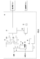
- FIG. 1 is a schematic configuration diagram showing an example of a configuration of a hydrogen sulfide gas production plant to which the present invention is applied.
- FIG. 2 is a flowchart of an exhaust method in the plant.
- FIG. 3 is a schematic configuration diagram showing a configuration of a conventional hydrogen sulfide gas production plant.
- FIG. 4 is a schematic configuration diagram showing a configuration of a conventional hydrogen sulfide gas production plant.
- the hydrogen sulfide gas production plant according to the present invention is included in at least a reaction facility for generating hydrogen sulfide gas by sulfur and hydrogen gas, a plurality of cooling facilities for cooling the generated hydrogen sulfide gas, and hydrogen sulfide gas.
- this hydrogen sulfide gas production plant is operated under high temperature and high pressure conditions, hydrogen sulfide gas may leak.
- this hydrogen sulfide gas production plant even if it is leaked, it is determined whether or not the leaked hydrogen sulfide gas needs to be rendered harmless, and only when necessary, the hydrogen sulfide gas is treated with the gas treatment facility.
- the treatment is not required, that is, when there is no influence on the environment or the human body even if exhausted to the atmosphere, the operation of the gas processing facility can be reduced by exhausting to the atmosphere.
- the hydrogen sulfide gas production plant may be further provided with a nitrogen gas supply facility for supplying nitrogen gas to the reaction facility or the like.
- the hydrogen sulfide gas is removed together with the nitrogen gas from the reaction facility or the like by the nitrogen gas ventilated in the facility.
- the nitrogen gas supply equipment it is judged whether it is necessary to detoxify the removed hydrogen sulfide gas in the same way as the exhaust equipment, and the hydrogen treatment gas is processed in the gas treatment equipment only when necessary.
- the operation of the gas processing facility can be reduced by exhausting to the atmosphere.
- FIG. 1 is a schematic diagram illustrating an example of a configuration of a hydrogen sulfide gas production plant 10.
- a hydrogen sulfide gas production plant 10 shown in FIG. 1 includes a reaction facility 11 for generating hydrogen sulfide gas, a plurality of cooling facilities 12 for cooling the generated hydrogen sulfide gas, and sulfur by removing sulfur in the hydrogen sulfide gas. And a sulfur removal facility 13 for supplying the hydrogen sulfide gas from which is removed.
- the hydrogen sulfide gas production plant 10 also includes a supply pipe 14 that supplies the hydrogen sulfide gas from which sulfur has been removed in the sulfur removal facility 13 to the sulfurization treatment plant.
- the hydrogen sulfide gas production plant 10 collects and stores the sulfur removed by the sulfur removal equipment 13 and adjusts the heat balance in the blowdown equipment 15 that supplies the sulfur treatment equipment and the reaction equipment 11. Therefore, a sulfur cooling facility 16 for cooling sulfur is provided.
- the hydrogen sulfide gas production plant 10 includes, for example, a gas treatment facility 17 for detoxifying the hydrogen sulfide gas leaked from the reaction facility 11, the cooling facility 12, and the sulfur removal facility 13, and the reaction facility 11, the cooling facility 12, and the sulfur removal. And an exhaust facility 18 for exhausting the hydrogen sulfide gas leaked from the facility 13 to the atmosphere or the gas processing facility 17.
- the hydrogen sulfide gas production plant 10 may include a nitrogen gas supply facility 19 for supplying nitrogen gas to the reaction facility 11 and the like.
- the reaction facility 11 includes, for example, a reactor 20, a quench tower 21, a heater 22, and a building 23.
- the reaction facility 11 generates a hydrogen sulfide gas generation reaction by the supplied sulfur and hydrogen gas, and generates hydrogen sulfide gas. More specifically, the molten sulfur is stored in the reactor 20, and hydrogen gas is supplied from the lower part thereof, so that the reaction proceeds while the upward flow of the hydrogen gas passes through the molten sulfur, and the hydrogen sulfide gas is generated. appear.
- Most of the hydrogen sulfide gas generated here is hydrogen sulfide, but part of it contains sulfur vapor that is entrained when the hydrogen gas passes through the reactor 20.
- the reaction facility 11 is operated under relatively high temperature and high pressure conditions of a temperature of about 470 ° C. and a pressure of about 800 kPaG, and the generated hydrogen sulfide gas is also at a high temperature and pressure.
- the hydrogen sulfide gas generated in the reaction facility 11 is about 150 ° C. when passing through the quench tower 21 as a result of heat exchange with the supplied sulfur.
- the reaction facility 11 Since the reaction facility 11 is operated under high temperature and high pressure conditions, a part of the generated hydrogen sulfide gas may leak from the reactor 20 or the quencher 21. In the reaction facility 11, the reactor 20, the quench tower 21, and the like are surrounded by the building 23, so that even if part of the hydrogen sulfide gas leaks, it is not directly exhausted into the atmosphere but remains in the building 23. The hydrogen sulfide gas accumulated in the building 23 is exhausted by an exhaust facility 18 described later.
- the cooling facility 12 collects hydrogen sulfide gas generated in the reaction facility 11.
- the cooling temperature of the hydrogen sulfide gas in the cooling facility 12 is not particularly limited, and is preferably lower in order to reduce the sulfur content in the hydrogen sulfide gas. Specifically, since normal (cooling) water is used, it is cooled to about 50 ° C.
- the hydrogen sulfide gas production plant 10 is provided with a plurality of cooling facilities 12.
- a part of the sulfur contained in the recovered hydrogen sulfide gas is solidified and fixed inside the facility (heat transfer surface). For this reason, by providing a plurality of cooling facilities 12, they can be used by alternately switching them to prevent a decrease in operating efficiency due to a decrease in cooling capacity.
- the hydrogen sulfide gas production plant 10 shown in FIG. 1 is an example having two systems of cooling facilities 12A and 12B.
- cooling facilities 12A and 12B for example, a jacket is provided around the lower portion thereof, and the fixed sulfur can be melted by heating with steam.
- the cooling facilities 12A and 12B for example, when sulfur is fixed inside the cooling facility 12A, the use of the cooling facility 12A is stopped and switched to the cooling facility 12B. In the cooling facility 12A whose use has been stopped, sulfur fixed by steam is melted and recovered.
- the cooling facilities 12A and 12B have cooled the hydrogen sulfide gas until just before the facilities whose use has been temporarily suspended, the high-pressure and high-concentration hydrogen sulfide gas is held therein. Therefore, in the melt recovery process of sulfur fixed inside, it is necessary to discharge the hydrogen sulfide gas in the cooling facilities 12A and 12B for melting and recovering the sulfur and reduce the internal pressure. In the hydrogen sulfide gas production plant 10, the hydrogen sulfide gas discharged at this time becomes so-called waste hydrogen sulfide gas, which is generated in the cooling facilities 12A and 12B.
- the waste hydrogen sulfide gas is discharged to the blowdown facility 15 described later together with the sulfur melted and recovered in the cooling facilities 12 ⁇ / b> A and 12 ⁇ / b> B. And is discharged from an outlet 24 provided in the blow-down facility 15.
- the waste hydrogen sulfide gas generated in the cooling facilities 12A and 12B may be directly discharged from the discharge ports provided in the cooling facilities 12A and 12B.
- the cooling facilities 12A and 12B are provided in the building 25. Since the cooling facilities 12A and 12B hold high-pressure and high-concentration hydrogen sulfide gas, the hydrogen sulfide gas may leak. By surrounding the cooling facilities 12 ⁇ / b> A and 12 ⁇ / b> B with the building 25, even if part of the hydrogen sulfide gas leaks, it is not exhausted directly into the atmosphere, but remains in the building 25. Further, when the waste hydrogen sulfide gas is directly discharged from the discharge port, the waste hydrogen sulfide gas may be discharged into the building 25. The hydrogen sulfide gas and waste hydrogen sulfide gas accumulated in the building 25 are exhausted from the building 25 by an exhaust facility 18 described later.
- the sulfur removal facility (knockout facility) 13 removes sulfur mixed in the hydrogen sulfide gas cooled by the cooling facilities 12A and 12B. Then, the sulfur removal facility 13 supplies the hydrogen sulfide gas from which sulfur has been removed to a sulfidation treatment plant that uses the hydrogen sulfide gas.
- the hydrogen sulfide gas generated in the reaction facility 11 partially contains sulfur vapor.
- the sulfur vapor is solidified and deposited on the bottom, and is melted and recovered by, for example, heating with steam through a jacket installed in the outer periphery of the lower part.
- the recovered sulfur is transferred to a blowdown facility 15 described later.
- the sulfur treatment plant to which the sulfur removal facility 13 supplies the hydrogen sulfide gas may be the same as or different from the treatment plant A that supplies the waste hydrogen sulfide gas via the pipe 31 described later.
- the sulfidation treatment plant include a sulfidation process plant and a dezincification process plant used in a hydrometallurgy method of nickel oxide ore.
- the sulfur removal facility 13 is provided in the building 26 in preparation for leakage of hydrogen sulfide gas. By surrounding the sulfur removal equipment 13 with the building 26, even if a part of the hydrogen sulfide gas leaks, it is not exhausted directly into the atmosphere but remains in the building 26.
- the hydrogen sulfide gas accumulated in the building 26 is exhausted from the building 26 by an exhaust facility 18 described later.
- the supply pipe 14 led out from the sulfur removal facility 13 is connected to the sulfidation treatment plant, and supplies hydrogen sulfide gas from which sulfur has been removed to the sulfidation treatment plant.
- the supply pipe 14 is provided with an ON / OFF valve 27 for controlling the supply of hydrogen sulfide gas to the sulfidation treatment plant.
- the supply pipe 14 includes a pressure gauge 28 for measuring the pressure of the hydrogen sulfide gas supplied to the sulfidation treatment plant, a flow meter 29 for measuring the flow rate of the hydrogen sulfide gas, and a control for controlling the supply of the hydrogen sulfide gas.
- a valve 30 is provided.
- the blow-down facility 15 recovers sulfur removed from the hydrogen sulfide gas by the sulfur removal facility 13. Moreover, the blowdown facility 15 collects sulfur that has adhered to the cooling facilities 12A and 12B. The blow-down facility 15 supplies the recovered sulfur to, for example, a sulfur treatment plant using the supply pump 30. Alternatively, the recovered sulfur may be recycled as a sulfur source to be supplied to the reaction facility 11 again.
- the blow-down facility 15 is provided with a discharge port 24 for discharging waste hydrogen sulfide gas generated in the cooling facilities 12A and 12B and discharged to the blow-down facility 15 to the outside of the system.
- the blow-down facility 15 is connected to a treatment plant A that uses hydrogen sulfide gas by connecting a pipe 31 to the discharge port 24, and waste discharged from the discharge port 24. Hydrogen sulfide gas is supplied to the processing plant A through the pipe 31.
- the processing plant A which supplies waste hydrogen sulfide gas does not specifically limit as the processing plant A which supplies waste hydrogen sulfide gas. What is necessary is just a processing plant which uses hydrogen sulfide gas.
- a processing plant which uses hydrogen sulfide gas for example, a sulfidation process plant or a dezincification process plant used in the above-described method for hydrometallizing nickel oxide ore can be used.
- the treatment plant A has a working pressure of the hydrogen sulfide gas lower than the operating pressure condition (780 to 800 kPaG) in the reaction equipment 11 of the plant 10. It is preferable in that waste hydrogen sulfide gas can be supplied.
- the sulfur cooling facility 16 cools sulfur from about 470 ° C. to about 150 ° C. in order to adjust the heat balance in the reaction facility 11.
- the sulfur cooling facility 16 supplies the cooled sulfur to, for example, the blowdown facility 15 and supplies it to the sulfur treatment plant and the like together with the sulfur recovered from the cooling facilities 12A and 12B and the sulfur removal facility 13.
- the sulfur cooling facility 16 may circulate and use the cooled sulfur as a sulfur source to be supplied to the reaction facility 11 again using the circulation pump 32.
- the gas treatment facility 17 is a detoxification facility that neutralizes the hydrogen sulfide gas leaked from each facility with a neutralizing agent such as caustic soda to make it harmless, and detoxifies the hydrogen sulfide gas by burning it to reduce toxicity
- a neutralizing agent such as caustic soda
- the gas treatment facility 17 is connected to an exhaust facility 18 and a nitrogen gas supply facility 19 which will be described later, and detoxifies the hydrogen sulfide gas sent from these facilities.
- the exhaust facility 18 is provided in, for example, the reaction facility 11 that generates hydrogen sulfide gas, the cooling facility 12 that processes the hydrogen sulfide gas, and the sulfur removal facility 13.
- the exhaust facility 18 is not limited to being provided in these facilities, and may be provided in other facilities where hydrogen sulfide gas may leak in the hydrogen sulfide gas production plant 10.
- the exhaust facility 18 has an exhaust pipe 40 that exhausts hydrogen sulfide gas to the atmosphere.
- the exhaust pipe 40 is led out from the buildings 23, 25, and 26 and connected to the atmosphere.
- the exhaust pipe 40 is connected to the first exhaust pipe 40 a that exhausts hydrogen sulfide gas into the atmosphere and the gas processing facility 17.
- One end is branched to the second exhaust pipe 40b to be exhausted.
- the exhaust equipment 18 is provided between the buildings 23, 25, and 26 and the branch point of the exhaust pipe 40, and a concentration measuring device 41 that measures the concentration of leaked hydrogen sulfide gas, and a measurement by the concentration measuring device 41.
- a valve mechanism 42 for controlling the exhaust of the first exhaust pipe 40a and the second exhaust pipe 40b based on the result is provided.
- the type and arrangement of the valves are not limited as long as the valve mechanism 42 can control the exhaust of the first exhaust pipe 40a and the second exhaust pipe 40b.
- the type of the valve mechanism 42 is, for example, an ON / OFF valve, but is not limited to this, and a control valve may be used.
- a control valve By switching ON / OFF of the valve mechanism 42, separation / connection between the buildings 23, 25, 26 and the atmosphere and the gas processing facility 17 can be switched.
- the ON / OFF valve provided in the first exhaust pipe 40a is referred to as a first ON / OFF valve 42a
- the ON / OFF valve provided in the second exhaust pipe 40b is referred to as a second ON / OFF valve 42b.
- the first ON / OFF valve 42a and the second ON / OFF valve 42b are normally in an OFF state, that is, the first exhaust pipe 40a and the second exhaust pipe 40b are closed.
- the exhaust facility 18 may be provided with a fan 43 between the concentration measuring device 41 and the branch point in order to improve the flow of hydrogen sulfide gas, for example.
- the exhaust facility 18 may be provided with an alarm so that an alarm is generated depending on the concentration of hydrogen sulfide gas.
- the concentration of the hydrogen sulfide gas leaked into the buildings 23, 25, and 26 is measured by the concentration measuring device 41.
- the first ON / OFF is performed.
- the valve 42a is turned on to be opened, the buildings 23, 25, and 26 are connected to the atmosphere via the first exhaust pipe 40a, the second ON / OFF valve 42b is turned off, and the second exhaust pipe
- the buildings 23, 25, and 26 are not connected to the gas processing facility 17 through 40b.
- the first ON / OFF valve 42a is turned off and closed, and the building is connected via the first exhaust pipe 40a.
- the second ON / OFF valve 42b is turned ON, and the buildings 23, 25, 26 and the gas processing equipment 17 are connected via the second exhaust pipe 40b.
- the hydrogen sulfide gas in the buildings 23, 25 and 26 is exhausted to the gas processing facility 17.
- the control of the ON / OFF valves 42a and 42b is based on the measurement result by the concentration measuring device 41 to determine whether or not the concentration of the hydrogen sulfide gas is a concentration at which the hydrogen sulfide gas may be exhausted to the atmosphere. ON or OFF control is performed.
- Hydrogen sulfide gas is said to be highly dangerous, but if the concentration is low, it will not affect the environment or the human body even if it is exhausted to the atmosphere.
- a concentration of 1 ppm is a working environment management concentration in the Industrial Safety and Health Law
- 5 ppm is an allowable concentration in the Japan Society for Occupational Health
- 50 to 100 ppm is said to cause symptoms, start-up irritation, conjunctivitis, and the like. That is, if the concentration is less than 5 ppm, it can be said that there is no influence on the human body or the environment.
- the predetermined concentration of the hydrogen sulfide gas is 5 ppm. That is, in the exhaust equipment 18, when the concentration of the hydrogen sulfide gas is less than 5 ppm as measured by the concentration measuring device 41, the hydrogen sulfide gas is exhausted from the first exhaust pipe 40a to the atmosphere, and the concentration is 5 ppm or more. In some cases, it is preferable to control the valve mechanism 42 so as to exhaust the hydrogen sulfide gas from the second exhaust pipe 40 b to the gas processing facility 17 in order to render the hydrogen sulfide gas harmless in the gas processing facility 17. An alarm may be sounded when 1 ppm is reached.
- the concentration of the hydrogen sulfide gas leaked by the concentration measuring device 41 is measured.
- the concentration is, for example, less than 5 ppm
- the hydrogen sulfide gas is exhausted to the atmosphere.
- the hydrogen sulfide gas production plant 10 it is not necessary to always operate the gas treatment facility 17.
- the abatement facility it is not necessary to always neutralize the hydrogen sulfide gas to make it harmless. Usage can be reduced and costs can be reduced.
- the installation position of the valve mechanism 42 is not limited to being provided in the first exhaust pipe 40a and the second exhaust pipe 40b, but the first exhaust pipe 40a and the second exhaust pipe 40b.
- One valve may be provided at the branch point as long as one of the valves is opened and the other is closed.
- the nitrogen gas supply facility 19 is a portion in which hydrogen sulfide gas such as the flange portion is liable to leak in order to avoid an explosion limit in the reactor 20 or the quench tower 21 of the reaction facility 11 having severe operating conditions in the hydrogen sulfide gas production plant 10. Nitrogen gas is constantly flowing. In the hydrogen sulfide gas production plant 10, by always supplying nitrogen gas to the flange portion or the like, the explosion limit can be avoided by removing the hydrogen sulfide gas leaked with the nitrogen gas from the reaction facility.
- the hydrogen sulfide gas production plant 10 is separated from the hydrogen sulfide gas production plant 10 and the processing plant at the time of predetermined periodic inspection, sudden trouble occurrence, or when the plant is started up. A process of replacing the inside of the plant 10 with nitrogen gas or the like is performed. For this reason, in such a case, the nitrogen gas supply equipment 19 supplies nitrogen gas into the plant 10.
- FIG. 1 shows a nitrogen gas supply facility 19 that supplies nitrogen gas to the flanges and the like of the reactor 20 and the quench tower 21 and omits the nitrogen gas supply facility at the time of periodic inspection.
- nitrogen gas is supplied from the outside of the reactor 20 and the quench tower 21 to a portion where hydrogen sulfide gas easily leaks, such as a flange, and ventilated. Thereby, when nitrogen gas passes through a flange part etc., hydrogen sulfide gas is extruded from a flange part etc. with nitrogen gas.
- the hydrogen sulfide gas extruded together with the nitrogen gas is normally detoxified in the gas treatment facility 17 by neutralization or combustion.
- the nitrogen gas supply equipment 19 has a mixed gas exhaust pipe 45 that exhausts nitrogen gas supplied to the reactor 20 and the quench tower 21 via the supply pipe 44 and hydrogen sulfide gas removed from the flange portion and the like.
- the mixed gas exhaust pipe 45 is branched at one end into a first mixed gas exhaust pipe 45a that exhausts nitrogen gas and hydrogen sulfide gas to the atmosphere and a second mixed gas exhaust pipe 45b that exhausts the gas processing equipment 17. is doing.
- the nitrogen gas supply equipment 19 is provided between the reactor 20 and the quench tower 21 and the branch point of the mixed gas exhaust pipe 45, and a concentration measuring device 46 for measuring the concentration of the removed hydrogen sulfide gas, and a concentration measurement
- a concentration measuring device 46 for measuring the concentration of the removed hydrogen sulfide gas
- a concentration measurement A valve mechanism 47 for controlling the exhaust of the first mixed gas exhaust pipe 45a and the second mixed gas exhaust pipe 45b based on the measurement result of the vessel 46 is provided.
- the type and arrangement of the valve are not limited as long as the valve mechanism 47 can control the exhaust of the first mixed gas exhaust pipe 45a and the second mixed gas exhaust pipe 45b.
- the type of the valve mechanism 47 is, for example, an ON / OFF valve, but is not limited to this, and a control valve may be used.
- a control valve By switching ON / OFF of the valve mechanism 47, separation / connection between the reactor 20 and the quench tower 21 and the atmosphere and the gas processing facility 17 can be switched.
- the ON / OFF valve provided in the first mixed gas exhaust pipe 45a is the first ON / OFF valve 47a
- the ON / OFF valve provided in the second mixed gas exhaust pipe 45b is the second ON / OFF valve.
- the OFF valve 47b is used.
- the first ON / OFF valve 47a and the second ON / OFF valve 47b are normally in an OFF state, that is, the first mixed gas exhaust pipe 45a and the second mixed gas exhaust pipe 45b are closed.
- the nitrogen gas supply equipment 19 may be provided with a fan 48 for improving the flow of nitrogen gas and hydrogen sulfide gas between the concentration measuring device 46 and the branch point, for example.
- the nitrogen gas supply equipment 19 measures the concentration of the removed hydrogen sulfide gas with the concentration measuring device 46, and when the measurement result of the concentration measuring device 46 is less than a predetermined concentration, the first ON / OFF valve 47a is turned on.
- the reactor 20 and the quench tower 21 are connected to the atmosphere via the first mixed gas exhaust pipe 45a, the second ON / OFF valve 47b is turned OFF, and the second mixed gas exhaust pipe 45b is connected.
- the reactor 20 and the quench tower 21 are not connected to the gas processing equipment 17 via the. By controlling in this way, the hydrogen sulfide gas and the nitrogen gas in the reactor 20 and the quench tower 21 are exhausted to the atmosphere.
- the first ON / OFF valve 47a is turned OFF and closed, and the first mixed gas exhaust pipe 45a is connected.
- the reactor 20 and the quench tower 21 are not connected to the atmosphere, the second ON / OFF valve 47b is turned on to be opened, and the reactor 20 and the quench tower 21 and the gas are connected via the second mixed gas exhaust pipe 45b.
- the processing equipment 17 is connected. By controlling in this way, the hydrogen sulfide gas and the nitrogen gas are exhausted to the gas processing facility 17.
- the control of the ON / OFF valve is the same as that of the exhaust equipment 18 described above.
- the concentration measuring device 46 Based on the measurement result by the concentration measuring device 46, it is determined whether or not the concentration of the hydrogen sulfide gas is a concentration that can be exhausted to the atmosphere. Judgment is made and ON or OFF control is performed.
- the nitrogen gas supply equipment 19 as in the exhaust equipment 18 described above, when the concentration of the hydrogen sulfide gas is less than 5 ppm as measured by the concentration measuring device 46, the hydrogen sulfide gas is removed from the first mixed gas exhaust pipe 45a.
- valve mechanism 47 When exhausted into the atmosphere and the concentration is 5 ppm or more, the valve mechanism 47 is configured to exhaust the hydrogen sulfide gas from the second mixed gas exhaust pipe 45b to the gas processing facility 17 in order to render the gas processing facility 17 harmless. It is preferable to control.
- the installation position of the valve mechanism 47 is not limited to being provided in each of the first mixed gas exhaust pipe 45 a and the second mixed gas exhaust pipe 45 b, but the first mixed gas exhaust pipe One valve may be provided at the branch point as long as the valve is one in which one of the 45a and the second mixed gas exhaust pipe 45b is opened and the other is closed.
- the concentration of the hydrogen sulfide gas leaked by the concentration measuring device 46 is measured.
- the concentration is less than 5 ppm, for example, the hydrogen sulfide gas is exhausted to the atmosphere.
- the hydrogen sulfide gas production plant 10 it is not necessary to always operate the gas treatment facility 17.
- the abatement equipment it is not always necessary to neutralize the hydrogen sulfide gas with the gas treatment facility 17 to make it harmless.
- the use of the neutralizing agent can be reduced, and the cost can be reduced.
- the hydrogen sulfide gas generated in the reaction facility 11 is cooled by the cooling facility 12, and the sulfur mixed in the sulfur removal facility 13 is removed to produce hydrogen sulfide gas. .
- the produced hydrogen sulfide gas is sent from the supply pipe 14 to a sulfur treatment plant that uses the hydrogen sulfide gas.
- waste hydrogen sulfide gas generated in the cooling facility 12 is recovered and supplied to the treatment plant A such as a sulfidation process plant.
- Hydrogen sulfide gas can be efficiently recovered and used effectively in the processing plant A.
- the waste hydrogen sulfide gas does not need to be processed by a flare facility or a gas processing facility as in the conventional case, the use cost of a recovery solvent such as caustic soda can be eliminated, and the operation cost can be greatly reduced.
- the gas processing facility 17 is used when exhausting the leaked hydrogen sulfide gas. If the concentration of hydrogen sulfide gas has little influence on the human body and the environment and there is no problem even if it is exhausted to the atmosphere, the operation of the gas treatment facility 17 may be reduced by exhausting to the atmosphere. it can. Thereby, in the hydrogen sulfide gas production plant 10, for example, the use amount of the neutralizing agent is reduced, and the cost can be reduced.
- step 1 the concentration measuring device 41 measures the concentration of hydrogen sulfide gas leaked into the buildings 23, 25, and 26 of the reaction facility 11, the cooling facility 12, and the sulfur removal facility 13. To do.
- step 2 it is determined whether or not the measurement result of the concentration measuring device 41 is less than a predetermined concentration.
- the predetermined concentration refers to a concentration that does not affect the environment or the human body even if the leaked hydrogen sulfide gas is exhausted to the atmosphere.
- 5 ppm is an allowable concentration in the Japan Society for Occupational Health, and 50 to 100 ppm is said to cause symptoms, start-up irritation, conjunctivitis, etc., so the predetermined concentration may be set to 5 ppm, for example. preferable.
- Step 3 the first ON / OFF valve 42a provided in the first exhaust pipe 40a is opened, and the second ON / OFF valve 42b provided in the second exhaust pipe 40b is closed.
- step 4 the first ON / OFF valve 42a is opened in step 3, and the second ON / OFF valve 42b is closed, so that the buildings 23, 25, 26 and the atmosphere are connected, and the buildings 23, 25, 26 and the gas treatment equipment 17 remain separated, so that a pressure difference occurs, and the hydrogen sulfide gas in the buildings 23, 25, 26 is exhausted to the atmosphere.
- Step 5 the first ON / OFF valve 42a provided in the first exhaust pipe 40a is closed, and the second ON / OFF valve 42b provided in the second exhaust pipe 40b is opened.
- step 6 the first ON / OFF valve 42a is closed in step 5, and the second ON / OFF valve 42b is opened, so that the buildings 23, 25, 26 and the gas processing equipment 17 are connected, and the buildings 23, 25, 26 and the atmosphere remain separated, so that a pressure difference occurs, and the hydrogen sulfide gas in the buildings 23, 25, 26 is transferred to the gas processing equipment 17. Exhausted.
- step 1 the concentration of hydrogen sulfide gas leaked to the flanges of the reactor 20 and the quench tower 21 is measured by a concentration measuring device 46 provided in the pipe 45.
- Step 2 it is determined whether or not the measurement result of the concentration measuring device 46 is less than a predetermined concentration.
- the predetermined concentration is the same as that in the case of the exhaust facility 18 and will not be described.
- Step 3 the first ON / OFF valve 47a provided in the first mixed gas exhaust pipe 45a is opened, and the second ON / OFF valve 47b provided in the second mixed gas exhaust pipe 45b is closed. .
- step 4 the first ON / OFF valve 47a is opened in step 3 and the second ON / OFF valve 47b is closed, so that the reactor 20 and the reactor 20 are connected via the first mixed gas exhaust pipe 45a. Since the quench tower 21 and the atmosphere are connected and the reactor 20 and the quench tower 21 and the gas processing equipment 17 remain separated, a pressure difference is generated, and the hydrogen sulfide gas in the reactor 20 and the quench tower 21 enters the atmosphere. Exhausted.
- Step 5 the first ON / OFF valve 47a provided in the first nitrogen gas pipe is closed, and the second ON / OFF valve 47b provided in the second mixed gas exhaust pipe 45b is opened.
- Step 6 the first ON / OFF valve 47a is closed in Step 5, and the second ON / OFF valve 47b is opened, so that the reactor 20 and the reactor 20 are connected via the second mixed gas exhaust pipe 45b. Since the quench tower 21 and the gas processing facility 17 are connected and the reactor 20 and the quench tower 21 and the atmosphere remain separated, a pressure difference is generated, and the hydrogen sulfide gas in the reactor 20 and the quench tower 21 is converted into the gas processing facility. 17 is exhausted.
- the exhaust gas is exhausted to the atmosphere according to the concentration of the hydrogen sulfide gas.
- the processing in the gas processing facility 17 can be reduced, and the cost can be reduced while maintaining the safety of the exhaust of the hydrogen sulfide gas.
- the hydrogen sulfide gas production plant 10 it is not necessary to always neutralize the hydrogen sulfide gas in the gas treatment equipment 17, for example, in the abatement equipment, so that the amount of neutralizing agent used can be reduced. . Thereby, in the hydrogen sulfide gas production plant 10, the cost can be reduced while maintaining the safety of the exhaust of the hydrogen sulfide gas. In addition, when a flare equipment is used for the gas treatment equipment 17, it is not necessary to always burn hydrogen sulfide gas to reduce toxicity, so that the generation of SOx can be reduced.
- the hydrogen sulfide gas production plant 10 all of the hydrogen sulfide gas removed together with the nitrogen gas in the nitrogen gas supply facility 19 is not exhausted to the gas treatment facility 17, and the neutralization treatment is required as in the exhaust facility 18. In the case where only the gas processing facility 17 can be exhausted to the atmosphere, the neutralization treatment in the gas processing facility 17 can be reduced by exhausting to the atmosphere. Therefore, in the hydrogen sulfide gas production plant 10, even when the nitrogen gas supply facility 19 is provided, the operation of the gas processing facility 17 can be reduced, and the cost of the hydrogen sulfide gas can be reduced while maintaining the safety of the exhaust of the hydrogen sulfide gas. The generation of SOx can be reduced.
- a hydrogen sulfide gas production plant 10 including a reaction facility 11, a cooling facility 12, a sulfur recovery facility 13, a gas treatment facility 17, an exhaust facility 18, and a nitrogen gas supply facility 19 is shown.
- the hydrogen sulfide gas production plant 10 may have a plurality of systems. In the case of having a plurality of systems, each plant 10 is connected, and even if inspection or trouble occurs in one plant 10, production of hydrogen sulfide gas is maintained by operating another plant 10. can do. Moreover, even if it has a some system
Landscapes
- Chemical & Material Sciences (AREA)
- Organic Chemistry (AREA)
- Chemical Kinetics & Catalysis (AREA)
- Inorganic Chemistry (AREA)
- Engineering & Computer Science (AREA)
- Health & Medical Sciences (AREA)
- Biomedical Technology (AREA)
- Environmental & Geological Engineering (AREA)
- Analytical Chemistry (AREA)
- General Chemical & Material Sciences (AREA)
- Oil, Petroleum & Natural Gas (AREA)
- Treating Waste Gases (AREA)
Abstract
Description
1.本発明の概要
2.硫化水素ガス製造プラント
3.硫化水素ガスの排気方法
本発明に係る硫化水素ガス製造プラントは、少なくとも、硫黄と水素ガスとにより硫化水素ガスを発生させる反応設備と、発生した硫化水素ガスを冷却する複数の冷却設備と、硫化水素ガス中に含まれる硫黄を除去する硫黄除去設備と、硫化水素ガスを無害化するガス処理設備と、ガス処理設備以外の設備から漏洩した硫化水素ガスを大気又はガス処理設備に排気する排気設備とを備える。
図1は、硫化水素ガス製造プラント10の構成の一例を示す概略図である。この図1に示される硫化水素ガス製造プラント10は、硫化水素ガスを発生させる反応設備11と、発生した硫化水素ガスを冷却する複数の冷却設備12と、硫化水素ガス中の硫黄を除去し硫黄が除去された硫化水素ガスを供給する硫黄除去設備13とを備える。また、硫化水素ガス製造プラント10は、硫黄除去設備13において硫黄が除去された硫化水素ガスを硫化処理プラントに供給する供給管14を備えている。
(反応設備)
反応設備11は、例えば、リアクター20と、クエンチタワー21と、ヒーター22と、建屋23とから構成されている。反応設備11は、供給された硫黄と水素ガスとにより硫化水素ガス生成反応を生じさせ、硫化水素ガスを発生させる。より具体的には、リアクター20内に熔融硫黄が貯留され、その下部から水素ガスが供給されることによって、水素ガスの上昇流が熔融硫黄を通過する間に反応が進行して硫化水素ガスが発生する。ここで発生した硫化水素ガスは、その大部分が硫化水素であるが、一部に水素ガスがリアクター20を通過する際に巻き込んだ硫黄蒸気が含まれている。
冷却設備12は、反応設備11にて発生した硫化水素ガスを回収する。冷却設備12における硫化水素ガスの冷却温度としては、特に限定されず、硫化水素ガス中の硫黄分を低減する上では低い方が好ましい。具体的には、通常(冷却)水を使用していることから、約50℃程度にまで冷却される。
硫黄除去設備(ノックアウト設備)13は、冷却設備12A,12Bにて冷却された硫化水素ガス中に混入した硫黄を除去する。そして、硫黄除去設備13は、硫黄が除去された硫化水素ガスを、硫化水素ガスを使用する硫化処理プラント等に供給する。
硫黄除去設備13から導出した供給管14は、硫化処理プラントに接続されており、硫黄を除去した硫化水素ガスを硫化処理プラントに供給する。供給管14には、硫化処理プラントに硫化水素ガスの供給を制御するON/OFFバルブ27が設けられている。また、供給管14には、硫化処理プラントへ供給される硫化水素ガスの圧力を測定する圧力計28と、硫化水素ガスの流量を測定する流量計29と、硫化水素ガスの供給を制御するコントロールバルブ30とが設けられている。
ブローダウン設備15は、硫黄除去設備13にて硫化水素ガスから除去された硫黄を回収する。また、ブローダウン設備15は、冷却設備12A,12B内に固着していた硫黄を回収する。そして、ブローダウン設備15は、それら回収した硫黄を供給ポンプ30を用いて例えば硫黄処理プラント等に供給する。または、回収した硫黄を、再び反応設備11に対して供給する硫黄源として循環利用させてもよい。
硫黄冷却設備16は、反応設備11における熱バランスを調整するために硫黄を約470℃から約150℃まで冷却する。また、硫黄冷却設備16は、冷却した硫黄を例えばブローダウン設備15に供給し、冷却設備12A,12Bや硫黄除去設備13から回収した硫黄と共に硫黄処理プラント等に供給する。また、硫黄冷却設備16は、冷却した硫黄を循環ポンプ32を用いて再び反応設備11に供給する硫黄源として循環利用させてもよい。
ガス処理設備17は、例えば各設備から漏洩した硫化水素ガスを苛性ソーダ等の中和剤を用いて中和して無害化する除害設備、硫化水素ガスを燃焼させて毒性を低下させて無害化するフレアー設備等であり、中和剤を使用する除害設備が好ましいが、硫化水素ガスを無害化することができれば特に限定されるものではない。ガス処理設備17は、後述する排気設備18及び窒素ガス供給設備19と接続され、これらの設備から送られてきた硫化水素ガスを無害化処理する。
排気設備18は、例えば、硫化水素ガスを生成する反応設備11、硫化水素ガスを処理する冷却設備12、硫黄除去設備13にそれぞれ設けられている。なお、排気設備18は、これらの設備に設けられることに限らず、硫化水素ガス製造プラント10において硫化水素ガスの漏洩のおそれがある他の設備に設けてもよい。
窒素ガス供給設備19は、硫化水素ガス製造プラント10の中でも運転条件が厳しい反応設備11のリアクター20やクエンチタワー21において爆発限界を避けるため、これらのフランジ部等の硫化水素ガスが漏洩しやすい部分に常時窒素ガスを流している。硫化水素ガス製造プラント10では、窒素ガスをフランジ部等に常時供給することで、窒素ガスで漏洩した硫化水素ガスを反応設備から除去することで爆発限界を避けることができる。また、硫化水素ガス製造プラント10では、所定の定期点検時や突発のトラブル発生時、又はプラント立ち上げに際しては、その硫化水素ガス製造プラント10と処理プラントとを切り離した上で、硫化水素ガス製造プラント10の内部を窒素ガス等によって置換する処理が行われる。このため、このような場合において、窒素ガス供給設備19は、プラント10内に窒素ガスを供給する。なお、図1では、リアクター20及びクエンチタワー21のフランジ部等に窒素ガスを供給する窒素ガス供給設備19を示し、定期点検時等における窒素ガス供給設備については省略する。
次に、硫化水素ガス製造プラント10の具体的な排気方法について説明する。なお、各設備に設けた排気設備18は、漏洩した硫化水素ガス濃度に応じてそれぞれ単独で稼働するようになっている。
図1では、反応設備11と、冷却設備12と、硫黄回収設備13と、ガス処理設備17と、排気設備18と、窒素ガス供給設備19とを備える硫化水素ガス製造プラント10を示したが、このことに限定されず、この硫化水素ガス製造プラント10を複数系統有するものであってもよい。複数の系統を有する場合には、各プラント10は接続されており、一つのプラント10について点検やトラブルが発生した場合であっても他のプラント10を稼働させることで硫化水素ガスの製造を維持することができる。また、このように複数の系統を有する場合であっても、各プラントにおいて上述した硫化水素ガス製造プラントと同様に排気設備や窒素ガス供給設備によりガス処理設備の稼働を抑制することができる。
Claims (12)
- 少なくとも、硫黄と水素ガスとにより硫化水素ガスを発生させる反応設備と、発生した硫化水素ガスを冷却する冷却設備と、該硫化水素ガス中に含まれる硫黄を除去する硫黄除去設備と、上記硫化水素ガスを無害化するガス処理設備とを備える硫化水素ガス製造プラントであって、
上記反応設備、上記冷却設備及び上記硫黄除去設備に設けられ、それらの設備から漏洩した硫化水素ガスを排気する排気設備を有し、
上記排気設備は、
漏洩した硫化水素ガスを大気に排気する第1の排気管と上記ガス処理設備に排気する第2の排気管とに一端が分岐した排気管と、
上記設備と上記排気管における分岐点との間に設けられ、上記硫化水素ガスの濃度を測定する濃度測定器と、
上記濃度測定器が所定の濃度未満の濃度を検出した場合には上記第1の排気管から上記硫化水素ガスを大気中へ排気し、所定の濃度以上の濃度を検出した場合には上記第2の排気管から上記硫化水素ガスを上記ガス処理設備へ排気するように制御するバルブ機構と
を有することを特徴とする硫化水素ガス製造プラント。 - 上記バルブ機構は、上記第1の排気管に設けられ、該第1の排気管を介した上記大気への排気を制御する第1のバルブと、上記第2の排気管に設けられ、該第2の排気管を介した上記ガス処理設備への排気を制御する第2のバルブとからなることを特徴とする請求項1記載の硫化水素ガス製造プラント。
- 上記排気管には、上記濃度測定器と上記分岐点との間にファンが設けられていることを特徴とする請求項1記載の硫化水素ガス製造プラント。
- 更に、少なくとも上記反応設備に窒素ガスを供給し、漏洩した硫化水素ガスを該反応設備から除去する窒素ガス供給設備を有し、
上記窒素ガス供給設備は、
上記窒素ガスと共に上記漏洩した硫化水素ガスを上記大気に排気する第1の混合ガス排気管と上記ガス処理設備に排気する第2の混合ガス排気管とに一端が分岐している混合ガス排気管と、
上記反応設備と上記混合ガス排気管における分岐点との間に設けられ、上記硫化水素ガスの濃度を測定する濃度測定器と、
上記濃度測定器が所定の濃度未満の濃度を検出した場合には上記第1の混合ガス排気管から上記窒素ガスと上記硫化水素ガスを大気中へ排気し、所定の濃度以上の濃度を検出した場合には上記第2の混合ガス排気管から上記窒素ガスと上記硫化水素ガスを上記ガス処理設備に排気するように制御するバルブ機構と
を有することを特徴とする請求項1記載の硫化水素ガス製造プラント。 - 上記窒素ガス供給設備のバルブ機構は、上記第1の混合ガス排気管に設けられ、該第1の混合ガス排気管を介した上記大気への排気を制御する第1のバルブと、上記第2の混合ガス排気管に設けられ、該第2の混合ガス排気管を介した上記ガス処理設備への排気を制御する第2のバルブとからなることを特徴とする請求項4記載の硫化水素ガス製造プラント。
- 上記混合ガス排気管には、上記濃度測定器と上記分岐点との間にファンが設けられていることを特徴とする請求項4記載の硫化水素ガス製造プラント。
- 上記硫化水素ガスの上記所定の濃度とは、5ppmであることを特徴とする請求項1記載の硫化水素ガス製造プラント。
- 少なくとも、硫黄と水素ガスとにより硫化水素ガスを発生させる反応設備と、発生した硫化水素ガスを冷却する冷却設備と、該硫化水素ガス中に含まれる硫黄を除去する硫黄除去設備と、上記硫化水素ガスを無害化するガス処理設備とを備える硫化水素ガス製造プラントにおける硫化水素ガスの排気方法であって、
上記硫化水素ガス製造プラントは、上記反応設備、上記冷却設備及び上記硫黄除去設備に設けられ、それらの設備から漏洩した硫化水素ガスを排気する排気設備を有し、
上記排気設備は、漏洩した上記硫化水素ガスを大気に排気する第1の排気管と上記ガス処理設備に排気する第2の排気管とに一端が分岐した排気管と、上記設備と上記排気管における上記分岐点との間に設けられ、該硫化水素ガスの濃度を測定する濃度測定器と、該濃度測定器が所定の濃度未満の濃度を検出した場合には上記第1の排気管から上記硫化水素ガスを大気中へ排気し、所定の濃度以上の濃度を検出した場合には上記第2の排気管から上記硫化水素ガスを上記ガス処理設備へ排気するように制御するバルブ機構とを有し、
上記濃度測定器が検出した濃度に基づいて上記バルブ機構を制御して上記第1の排気管から上記硫化水素ガスを大気中に排気するか、または上記第2の排気管から上記硫化水素ガスを上記ガス処理設備に排気することを特徴とする硫化水素ガスの排気方法。 - 上記バルブ機構が、上記第1の排気管に設けられ、該第1の排気管を介した上記大気への排気を制御する第1のバルブと、上記第2の排気管に設けられ、該第2の排気管を介した上記ガス処理設備への排気を制御する第2のバルブとからなり、
上記濃度測定器が所定の濃度未満の濃度を検出した場合には、上記第1の排気管に設けられた第1のバルブを開放し、上記第2のバルブを閉鎖して上記硫化水素ガスを大気中に排気し、
上記濃度測定器が所定の濃度以上の濃度を検出した場合には、上記第2のバルブを開放し、上記第1のバルブを閉鎖して上記硫化水素ガスを上記ガス処理設備に排気することを特徴とする請求項8記載の硫化水素ガスの排気方法。 - 上記硫化水素ガス製造プラントは、更に、少なくとも上記反応設備に窒素ガスを供給し、漏洩した硫化水素ガスを該反応設備から除去する窒素ガス供給設備を有し、
上記窒素ガス供給設備は、上記窒素ガスと共に上記漏洩した硫化水素ガスを上記大気に排気する第1の混合ガス排気管と上記ガス処理設備に排気する第2の混合ガス排気管とに一端が分岐している混合ガス排気管と、上記反応設備と該混合ガス排気管における分岐点との間に設けられ、上記硫化水素ガスの濃度を測定する濃度測定器と、上記濃度測定器が所定の濃度未満の濃度を検出した場合には上記第1の混合ガス排気管から上記窒素ガスと上記硫化水素ガスを大気中へ排気させ、所定の濃度以上の濃度を検出した場合には上記第2の混合ガス排気管から上記窒素ガスと上記硫化水素ガスを上記ガス処理設備に排気するように制御するバルブ機構とを有し、
上記濃度測定器が検出した濃度に基づいて上記バルブ機構を制御して上記窒素ガス及び上記硫化水素ガスを大気中に排気するか、または上記ガス処理設備に排気することを特徴とする請求項8記載の硫化水素ガスの排気方法。 - 上記窒素ガス供給設備のバルブ機構は、上記第1の混合ガス排気管に設けられ、該第1の混合ガス排気管を介した上記大気への排気を制御する第1のバルブと、上記第2の混合ガス排気管に設けられ、該第2の混合ガス排気管を介した上記ガス処理設備への廃棄を制御する第2のバルブとからなり、
上記濃度測定器が所定の濃度未満の濃度を検出した場合には、上記第1の混合ガス排気管に設けられた上記第1のバルブを開放し、上記第2の混合ガス排気管に設けられた上記第2のバルブを閉鎖して上記窒素ガスと上記硫化水素ガスを大気中に排気し、
上記濃度測定器が所定の濃度以上の濃度を検出した場合には、上記第2の混合ガス排気管に設けられた上記第2のバルブを開放し、上記第1の混合ガス排気管に設けられた上記第1のバルブを閉鎖して上記窒素ガスと上記硫化水素ガスを上記ガス処理設備に排気することを特徴とする請求項10記載の硫化水素ガスの排気方法。 - 上記硫化水素ガスの上記所定の濃度とは、5ppmであることを特徴とする請求項8記載の硫化水素ガスの排気方法。
Priority Applications (5)
| Application Number | Priority Date | Filing Date | Title |
|---|---|---|---|
| US14/767,200 US9550674B2 (en) | 2013-02-13 | 2013-12-10 | Plant for manufacturing hydrogen sulfide gas and method for exhausting hydrogen sulfide gas |
| AU2013378333A AU2013378333B2 (en) | 2013-02-13 | 2013-12-10 | Plant for manufacturing hydrogen sulfide gas and method for exhausting hydrogen sulfide gas |
| EP13874981.7A EP2957541B1 (en) | 2013-02-13 | 2013-12-10 | Plant for manufacturing hydrogen sulfide gas and method for exhausting hydrogen sulfide gas |
| CA2901184A CA2901184A1 (en) | 2013-02-13 | 2013-12-10 | Plant for manufacturing hydrogen sulfide gas and method for exhausting hydrogen sulfide gas |
| PH12015501773A PH12015501773A1 (en) | 2013-02-13 | 2015-08-12 | Plant for manufacturing hydrogen sulfide gas and method for exhausting hydrogen sulfide gas |
Applications Claiming Priority (2)
| Application Number | Priority Date | Filing Date | Title |
|---|---|---|---|
| JP2013-025398 | 2013-02-13 | ||
| JP2013025398A JP5545381B1 (ja) | 2013-02-13 | 2013-02-13 | 硫化水素ガス製造プラント及び硫化水素ガスの排気方法 |
Publications (1)
| Publication Number | Publication Date |
|---|---|
| WO2014125712A1 true WO2014125712A1 (ja) | 2014-08-21 |
Family
ID=51353731
Family Applications (1)
| Application Number | Title | Priority Date | Filing Date |
|---|---|---|---|
| PCT/JP2013/083091 Ceased WO2014125712A1 (ja) | 2013-02-13 | 2013-12-10 | 硫化水素ガス製造プラント及び硫化水素ガスの排気方法 |
Country Status (7)
| Country | Link |
|---|---|
| US (1) | US9550674B2 (ja) |
| EP (1) | EP2957541B1 (ja) |
| JP (1) | JP5545381B1 (ja) |
| AU (1) | AU2013378333B2 (ja) |
| CA (1) | CA2901184A1 (ja) |
| PH (1) | PH12015501773A1 (ja) |
| WO (1) | WO2014125712A1 (ja) |
Families Citing this family (5)
| Publication number | Priority date | Publication date | Assignee | Title |
|---|---|---|---|---|
| JP5494754B2 (ja) * | 2012-07-31 | 2014-05-21 | 住友金属鉱山株式会社 | 硫化水素ガス製造プラントシステム及び硫化水素ガスの回収利用方法 |
| SG11201804843TA (en) * | 2015-12-10 | 2018-07-30 | Chevron Phillips Chemical Co Lp | Hydrogen sulfide production process and related reactor vessels |
| JP2019054200A (ja) * | 2017-09-19 | 2019-04-04 | 東芝メモリ株式会社 | 抵抗変化型メモリ |
| JP7115227B2 (ja) * | 2018-11-05 | 2022-08-09 | 住友金属鉱山株式会社 | 硫化水素ガス製造プラント、硫化水素ガスの製造方法 |
| CN115970458B (zh) * | 2021-10-15 | 2024-08-09 | 中国石油化工股份有限公司 | 一种硫化氢泄漏捕集处理装置及方法 |
Citations (7)
| Publication number | Priority date | Publication date | Assignee | Title |
|---|---|---|---|---|
| JPS4943447A (ja) * | 1972-08-31 | 1974-04-24 | ||
| JP2005205346A (ja) * | 2004-01-23 | 2005-08-04 | Sumitomo Metal Mining Co Ltd | 15nの製造方法及びそれを利用した硫酸或いは硫酸カルシウムの製造方法 |
| JP2009234806A (ja) * | 2008-03-25 | 2009-10-15 | Sumitomo Chemical Co Ltd | 再生硫黄回収装置 |
| JP2010030866A (ja) * | 2008-07-31 | 2010-02-12 | Sumitomo Chemical Co Ltd | 硫化水素ガスの精製方法。 |
| JP2010515658A (ja) * | 2007-01-16 | 2010-05-13 | ビーエーエスエフ ソシエタス・ヨーロピア | 硫化水素を連続的に製造するための方法および装置 |
| JP2010515660A (ja) * | 2007-01-16 | 2010-05-13 | ビーエーエスエフ ソシエタス・ヨーロピア | 硫化水素を連続的に製造するための方法および装置 |
| JP2010126778A (ja) | 2008-11-28 | 2010-06-10 | Sumitomo Metal Mining Co Ltd | ニッケル及びコバルトを含む硫化物の製造方法 |
Family Cites Families (5)
| Publication number | Priority date | Publication date | Assignee | Title |
|---|---|---|---|---|
| JPS4943447B1 (ja) * | 1970-11-20 | 1974-11-21 | ||
| US4478811A (en) | 1983-04-13 | 1984-10-23 | Union Oil Company Of California | Method for preventing sulfur emissions from vessels containing molten sulfur |
| US4861576A (en) | 1988-06-03 | 1989-08-29 | Phillips Petroleum Company | Method for reducing corrosion in a bypass system |
| JP4573106B2 (ja) * | 2004-12-20 | 2010-11-04 | 昌弘 小川 | 脱硫処理廃水からのアンモニアと硫化水素の分離回収方法。 |
| JP2013025398A (ja) | 2011-07-15 | 2013-02-04 | Tokyo Institute Of Technology | 識別器生成装置、方法及びプログラム、並びにクラス認識器、方法及びプログラム |
-
2013
- 2013-02-13 JP JP2013025398A patent/JP5545381B1/ja active Active
- 2013-12-10 US US14/767,200 patent/US9550674B2/en not_active Expired - Fee Related
- 2013-12-10 WO PCT/JP2013/083091 patent/WO2014125712A1/ja not_active Ceased
- 2013-12-10 CA CA2901184A patent/CA2901184A1/en not_active Abandoned
- 2013-12-10 EP EP13874981.7A patent/EP2957541B1/en not_active Not-in-force
- 2013-12-10 AU AU2013378333A patent/AU2013378333B2/en not_active Ceased
-
2015
- 2015-08-12 PH PH12015501773A patent/PH12015501773A1/en unknown
Patent Citations (7)
| Publication number | Priority date | Publication date | Assignee | Title |
|---|---|---|---|---|
| JPS4943447A (ja) * | 1972-08-31 | 1974-04-24 | ||
| JP2005205346A (ja) * | 2004-01-23 | 2005-08-04 | Sumitomo Metal Mining Co Ltd | 15nの製造方法及びそれを利用した硫酸或いは硫酸カルシウムの製造方法 |
| JP2010515658A (ja) * | 2007-01-16 | 2010-05-13 | ビーエーエスエフ ソシエタス・ヨーロピア | 硫化水素を連続的に製造するための方法および装置 |
| JP2010515660A (ja) * | 2007-01-16 | 2010-05-13 | ビーエーエスエフ ソシエタス・ヨーロピア | 硫化水素を連続的に製造するための方法および装置 |
| JP2009234806A (ja) * | 2008-03-25 | 2009-10-15 | Sumitomo Chemical Co Ltd | 再生硫黄回収装置 |
| JP2010030866A (ja) * | 2008-07-31 | 2010-02-12 | Sumitomo Chemical Co Ltd | 硫化水素ガスの精製方法。 |
| JP2010126778A (ja) | 2008-11-28 | 2010-06-10 | Sumitomo Metal Mining Co Ltd | ニッケル及びコバルトを含む硫化物の製造方法 |
Also Published As
| Publication number | Publication date |
|---|---|
| US9550674B2 (en) | 2017-01-24 |
| CA2901184A1 (en) | 2014-08-21 |
| JP2014152090A (ja) | 2014-08-25 |
| EP2957541A1 (en) | 2015-12-23 |
| PH12015501773B1 (en) | 2015-12-07 |
| US20160002038A1 (en) | 2016-01-07 |
| AU2013378333A1 (en) | 2015-10-01 |
| AU2013378333B2 (en) | 2017-07-20 |
| EP2957541A4 (en) | 2016-11-09 |
| JP5545381B1 (ja) | 2014-07-09 |
| PH12015501773A1 (en) | 2015-12-07 |
| EP2957541B1 (en) | 2018-01-31 |
Similar Documents
| Publication | Publication Date | Title |
|---|---|---|
| JP5545381B1 (ja) | 硫化水素ガス製造プラント及び硫化水素ガスの排気方法 | |
| CN101280926A (zh) | 废气净化装置及其净化方法 | |
| JP5700160B2 (ja) | 硫化水素ガス製造プラント及び硫化水素ガスの排気方法 | |
| KR101160815B1 (ko) | 폐열회수장치 | |
| WO2009125457A1 (ja) | シラン系ガス及びフッ素系ガス含有排ガスの処理方法及び該方法を用いた排ガス処理装置 | |
| JP2016540236A (ja) | 水素を除去しガス状媒体を浄化するシステム及びその使用方法 | |
| JP5659491B2 (ja) | フッ素ガス発生装置を含む半導体製造設備 | |
| CN104673401A (zh) | 用于密封合成气冷却器的系统和方法 | |
| JP5494754B2 (ja) | 硫化水素ガス製造プラントシステム及び硫化水素ガスの回収利用方法 | |
| CA2967812A1 (en) | Degassing system and device for degassing liquid sulfur | |
| JP5365708B2 (ja) | 硫化水素ガス製造プラント及び廃硫化水素ガスの回収利用方法 | |
| JP5682683B2 (ja) | 硫化水素ガス製造プラント及び廃硫化水素ガスの回収利用方法 | |
| JP5708849B2 (ja) | 硫化水素ガス製造プラントシステム及び硫化水素ガスの回収利用方法 | |
| JP2007044667A (ja) | 排ガス処理装置及び方法 | |
| JP5301113B2 (ja) | 銅系吸収剤の再利用方法 | |
| JP2017026244A (ja) | 排ガスの燃焼式浄化装置 | |
| JP6443359B2 (ja) | 排ガス処理設備の再生塔 | |
| JP5499149B2 (ja) | 排ガス処理方法 | |
| JP4545852B2 (ja) | 排ガス処理装置 | |
| JP2008031328A (ja) | プラスチック廃棄物の油化処理方法及び装置 | |
| WO2013169139A1 (en) | Method and arrangement for treating exhaust gas | |
| WO2025104691A1 (en) | Process and system for treatment of acid gases | |
| Trovant et al. | A Novel Dry-Based System for Safe, Hygienic Energy Recovery from Ferroalloy Furnace Exhaust | |
| JP2004085135A (ja) | 揮発性有機化合物の蓄熱燃焼式処理装置 | |
| JP2007204760A (ja) | 熱分解装置 |
Legal Events
| Date | Code | Title | Description |
|---|---|---|---|
| 121 | Ep: the epo has been informed by wipo that ep was designated in this application |
Ref document number: 13874981 Country of ref document: EP Kind code of ref document: A1 |
|
| WWE | Wipo information: entry into national phase |
Ref document number: 14767200 Country of ref document: US |
|
| ENP | Entry into the national phase |
Ref document number: 2901184 Country of ref document: CA |
|
| NENP | Non-entry into the national phase |
Ref country code: DE |
|
| WWE | Wipo information: entry into national phase |
Ref document number: IDP00201505643 Country of ref document: ID Ref document number: 2013874981 Country of ref document: EP |
|
| ENP | Entry into the national phase |
Ref document number: 2013378333 Country of ref document: AU Date of ref document: 20131210 Kind code of ref document: A |