WO2014126000A1 - 蛍光観察装置 - Google Patents
蛍光観察装置 Download PDFInfo
- Publication number
- WO2014126000A1 WO2014126000A1 PCT/JP2014/052808 JP2014052808W WO2014126000A1 WO 2014126000 A1 WO2014126000 A1 WO 2014126000A1 JP 2014052808 W JP2014052808 W JP 2014052808W WO 2014126000 A1 WO2014126000 A1 WO 2014126000A1
- Authority
- WO
- WIPO (PCT)
- Prior art keywords
- light
- fluorescence
- image
- light source
- white
- Prior art date
- Legal status (The legal status is an assumption and is not a legal conclusion. Google has not performed a legal analysis and makes no representation as to the accuracy of the status listed.)
- Ceased
Links
Images


Classifications
-
- A—HUMAN NECESSITIES
- A61—MEDICAL OR VETERINARY SCIENCE; HYGIENE
- A61B—DIAGNOSIS; SURGERY; IDENTIFICATION
- A61B1/00—Instruments for performing medical examinations of the interior of cavities or tubes of the body by visual or photographical inspection, e.g. endoscopes; Illuminating arrangements therefor
- A61B1/00163—Optical arrangements
- A61B1/00186—Optical arrangements with imaging filters
-
- A—HUMAN NECESSITIES
- A61—MEDICAL OR VETERINARY SCIENCE; HYGIENE
- A61B—DIAGNOSIS; SURGERY; IDENTIFICATION
- A61B1/00—Instruments for performing medical examinations of the interior of cavities or tubes of the body by visual or photographical inspection, e.g. endoscopes; Illuminating arrangements therefor
- A61B1/00002—Operational features of endoscopes
- A61B1/00004—Operational features of endoscopes characterised by electronic signal processing
- A61B1/00009—Operational features of endoscopes characterised by electronic signal processing of image signals during a use of endoscope
- A61B1/000094—Operational features of endoscopes characterised by electronic signal processing of image signals during a use of endoscope extracting biological structures
-
- A—HUMAN NECESSITIES
- A61—MEDICAL OR VETERINARY SCIENCE; HYGIENE
- A61B—DIAGNOSIS; SURGERY; IDENTIFICATION
- A61B1/00—Instruments for performing medical examinations of the interior of cavities or tubes of the body by visual or photographical inspection, e.g. endoscopes; Illuminating arrangements therefor
- A61B1/04—Instruments for performing medical examinations of the interior of cavities or tubes of the body by visual or photographical inspection, e.g. endoscopes; Illuminating arrangements therefor combined with photographic or television appliances
- A61B1/043—Instruments for performing medical examinations of the interior of cavities or tubes of the body by visual or photographical inspection, e.g. endoscopes; Illuminating arrangements therefor combined with photographic or television appliances for fluorescence imaging
-
- A—HUMAN NECESSITIES
- A61—MEDICAL OR VETERINARY SCIENCE; HYGIENE
- A61B—DIAGNOSIS; SURGERY; IDENTIFICATION
- A61B1/00—Instruments for performing medical examinations of the interior of cavities or tubes of the body by visual or photographical inspection, e.g. endoscopes; Illuminating arrangements therefor
- A61B1/06—Instruments for performing medical examinations of the interior of cavities or tubes of the body by visual or photographical inspection, e.g. endoscopes; Illuminating arrangements therefor with illuminating arrangements
- A61B1/0638—Instruments for performing medical examinations of the interior of cavities or tubes of the body by visual or photographical inspection, e.g. endoscopes; Illuminating arrangements therefor with illuminating arrangements providing two or more wavelengths
-
- A—HUMAN NECESSITIES
- A61—MEDICAL OR VETERINARY SCIENCE; HYGIENE
- A61B—DIAGNOSIS; SURGERY; IDENTIFICATION
- A61B1/00—Instruments for performing medical examinations of the interior of cavities or tubes of the body by visual or photographical inspection, e.g. endoscopes; Illuminating arrangements therefor
- A61B1/06—Instruments for performing medical examinations of the interior of cavities or tubes of the body by visual or photographical inspection, e.g. endoscopes; Illuminating arrangements therefor with illuminating arrangements
- A61B1/0646—Instruments for performing medical examinations of the interior of cavities or tubes of the body by visual or photographical inspection, e.g. endoscopes; Illuminating arrangements therefor with illuminating arrangements with illumination filters
Definitions
- the present invention relates to a fluorescence observation apparatus.
- Patent Document 1 Conventionally, there has been known a fluorescence observation apparatus that alternately acquires both a white light image and a fluorescence image of a living tissue in a time division manner (see, for example, Patent Document 1). According to Patent Document 1, even when the fluorescence wavelength is in the visible region and the fluorescence wavelength and the partial wavelength of the white light coincide with each other, the fluorescence and the white light are separated and photographed. be able to.
- Patent Document 1 since a white light image and a fluorescent image are obtained alternately, there is a problem that the frame rate of each image becomes slow. In particular, since the observer mainly observes the white light image, the reduction in the frame rate of the white light image hinders the observation for the observer.
- the present invention has been made in view of the circumstances described above, and is a fluorescence observation apparatus capable of acquiring a white light image and a fluorescent image in the visible region in parallel without slowing down the frame rate of the white light image.
- the purpose is to provide.
- the present invention provides the following means.
- the present invention provides a light source unit that irradiates a living tissue with illumination light including excitation light, and captures a return light image of the living tissue by photographing a return light that returns from the living tissue by irradiation of the illumination light from the light source unit.
- a fluorescence observation apparatus Provided is a fluorescence observation apparatus.
- the illumination light from the light source unit is irradiated onto the living tissue, whereby the return light image obtained by photographing the form of the living tissue is generated by the return light image generation unit.
- the excitation light included in the illumination light is irradiated onto the living tissue, whereby a fluorescent image obtained by photographing the fluorescence from the living tissue is acquired by the fluorescent image generation unit.
- both the return light and the fluorescence have wavelengths in the visible region, but have different wavelengths, so that the return light image generation unit and the fluorescence image generation unit are separately photographed.
- the return light image and the fluorescence image can be acquired in parallel without slowing down the frame rate of the return light image.
- light having a wavelength of 490 nm to 530 nm has a sufficiently small effect on a living tissue and hardly contributes to acquisition of information on the form of the living tissue. Therefore, even if the illumination light does not include at least a part of wavelengths from 490 nm to 540 nm, it is possible to obtain a return light image equivalent to a white light image in which the form of the biological tissue is captured sufficiently clearly. .
- the at least part of the wavelength region may be 510 nm to 530 nm.
- the width of the at least part of the wavelength region may be 20 nm or more.
- the light source unit includes a white light source that emits white light, and a filter that removes light in at least a part of a wavelength region from 490 nm to 540 nm from the white light emitted from the white light source,
- a filter may be provided so as to be detachable at a subsequent stage of the white light source, and the illumination light may be substantially white light transmitted through the filter.
- a living body when acquiring a fluorescent image, a living body is irradiated with substantially white light from which part of the wavelength region has been removed from white light as illumination light by inserting a filter after the white light source, so that the color of the living tissue is substantially reduced. It is possible to obtain a return light image that is accurately reproduced.
- the return light image generation unit when the filter is inserted in the subsequent stage of the white light source, and when the filter is removed from the subsequent stage of the white light source, the return light image generation unit generates the filter, respectively.
- the white balance switching unit can switch the white balance value required for the return light image at each time.
- the light source unit may intermittently irradiate the living tissue with another excitation light that generates another fluorescence having a wavelength different from that of the illumination light and the fluorescence. In this way, two types of fluorescence can be imaged simultaneously when another excitation light is irradiated on the living tissue.
- the said light source part may be provided with the near-infrared light source which emits a near-infrared light as said another excitation light.
- the white light image and the fluorescent image in the visible region can be acquired in parallel without reducing the frame rate of the white light image.
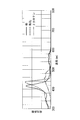
- FIG. 1 is an overall configuration diagram of a fluorescence observation apparatus according to a first embodiment of the present invention. It is a spectrum of the illumination light which the light source unit of FIG. 1 outputs, and the fluorescence excited by the excitation light contained in this illumination light. It is a figure explaining the effect
- FIG. 6 is a spectrum of illumination light and near infrared light output from the light source unit of FIG. 5 and two fluorescences excited by two excitation lights included in the illumination light and near infrared light. It is a timing chart explaining operation
- a fluorescence observation apparatus 1 which concerns on the 1st Embodiment of this invention is demonstrated with reference to FIGS. 1-4.
- a fluorescence observation apparatus 1 according to the present embodiment is an endoscope apparatus, and as shown in FIG. 1, an elongated insertion part 2 inserted into a body, a light source unit (light source part) 3, and the light source unit
- the illumination unit 4 that irradiates the illumination light L from 3 toward the living tissue X from the distal end 2a of the insertion portion 2, and the imaging that is provided at the distal end 2a of the insertion portion 2 and acquires image information S1 and S2 of the biological tissue X
- the unit 5 includes an image processing unit 6 that processes the image information S1 and S2 acquired by the imaging unit 5, and a display unit 7 that displays the images G1 and G2 processed by the image processing unit 6. .
- the light source unit 3 includes a white light source 31 such as a xenon lamp, a filter 32 that generates illumination light L by cutting out some wavelengths from white light emitted from the white light source 31, and the filter 32. And a coupling lens 33 for condensing the illumination light L.
- the white light source 31 emits white light having a wavelength over the entire visible region.
- the filter 32 transmits at least light with wavelengths of 400 nm to 490 nm and 540 nm to 610 nm and blocks light with wavelengths of 490 nm to 540 nm.
- illumination light L that is substantially white light having a wavelength distribution obtained by removing a part of the wavelength region from the visible region and having a bipolar distribution is generated.
- the illumination unit 4 includes a light guide fiber 41 disposed over almost the entire length of the insertion portion 2 in the longitudinal direction, and an illumination optical system 42 provided at the distal end 2a of the insertion portion 2.
- the light guide fiber 41 guides the illumination light L collected by the coupling lens 33.
- the illumination optical system 42 diffuses the illumination light L guided by the light guide fiber 41 and irradiates the living tissue X facing the distal end 2 a of the insertion portion 2.
- the imaging unit 5 includes an objective lens 51 that condenses the light from the living tissue X, a beam splitter 52 that divides the light collected by the objective lens 51 into two, and the light that is divided by the beam splitter 52.
- an image sensor 53 such as a color CCD and an image sensor 54 such as a high sensitivity monochrome CCD, and a barrier filter 55 disposed between the beam splitter 52 and the image sensor 54.
- Reference numeral 56 denotes an imaging lens that focuses light collected by the objective lens 51 on the imaging surfaces of the imaging elements 53 and 54.
- the barrier filter 55 blocks the return light of the illumination light L out of the light incident from the beam splitter 52 and selectively transmits fluorescence described later.
- the image processing unit 6 generates a return light image G1 from the return light image information S1 acquired by the image sensor 53, and a fluorescence image G2 from the fluorescence image information S2 acquired by the image sensor 54. And a fluorescent image generation unit 62 for generation.
- the return light image generation unit 61 and the fluorescence image generation unit 62 output the return light image G1 and the fluorescence image G2 to the display unit 7, respectively.
- the image processing unit 6 may output the return light image G1 and the fluorescence image G2 to the display unit 7 after appropriately performing image processing such as noise removal.
- the display unit 7 displays the return light image G1 and the fluorescence image G2 in parallel.
- a fluorescent dye that accumulates in a lesioned part is administered to the biological tissue X in advance.
- a fluorescent dye that is excited by light having a wavelength of 450 nm to 490 nm and generates fluorescence having a wavelength of 490 nm to 540 nm is used.
- FIG. 1 shows that the present embodiment, as shown in FIG.
- a fluorescein derivative having an excitation wavelength EXfl of about 450 nm to 500 nm and an emission wavelength EMfl of about 510 nm to 540 nm, which is used for labeling cancer. Is assumed.
- the insertion portion 2 is inserted into the body, and the distal end 2a thereof is disposed opposite to the biological tissue X, and the illumination light L is irradiated from the distal end 2a of the insertion portion 2 to the biological tissue X by the operation of the light source unit 3.
- the illumination light L is reflected on the surface of the living tissue X, and a part of the reflected illumination light L returns to the distal end 2a of the insertion portion 2.
- the illumination light L includes excitation light having a wavelength of 450 nm to 490 nm for exciting the fluorescent dye. Therefore, the fluorescent dye contained in the living tissue X is excited by the irradiation of the illumination light L, and a part of the generated fluorescence returns to the distal end 2a of the insertion portion 2 together with the return light of the illumination light L.
- the return light and the fluorescence of the illumination light L collected by the objective lens 51 at the tip 2a of the insertion portion 2 are divided into two by the beam splitter 52.
- One image is captured by the image sensor 53 and acquired as the return light image information S1
- the other image is captured by the image sensor 54 after only the fluorescence is extracted by the barrier filter 55 and acquired as the fluorescence image information S2.
- the image sensor 53 captures both the return light and the fluorescence of the illumination light L. Since the fluorescence is sufficiently weak with respect to the return light, the return light image information S1 acquired by the image sensor 53 is It mainly includes information on the form of the biological tissue X.
- a return light image G1 is generated from the return light image information S1
- a fluorescence image G2 is generated from the fluorescence image information S2. Then, the return light image G1 and the fluorescence image G2 are displayed on the display unit 7.
- FIG. 3 shows absorption spectra of main absorbers present in the living tissue X.
- hemoglobin (Hb) and oxygenated hemoglobin (HbO 2 ) present in the blood strongly absorb light having a wavelength of 400 nm to 450 nm in the surface layer of the biological tissue X, and have a wavelength in the deep layer of the biological tissue X.
- ⁇ -carotene accumulated in fat strongly absorbs light having a wavelength of 450 nm to 490 nm.
- light having a wavelength of 600 nm to 610 nm is hardly absorbed by any of Hb, HbO 2 and ⁇ -carotene.
- the illumination light L includes a wavelength region that is absorbed in fat and blood vessels and a wavelength region that is not absorbed in any of these. Therefore, the return light image G1 obtained by capturing the form of the living tissue X sufficiently clearly can be acquired in the same manner as the white light image acquired by illuminating the living tissue X with white light.
- the wavelength range that is not important for the acquisition of the information of the form of the living tissue X and that has a small amount of information on the form ie, 490 nm to 540 nm, is excluded from the illumination light L, and the wavelength removed from the illumination light L
- the fluorescence using the illumination light L in the region 490 nm to 540 nm it is possible to acquire both the return light image G1 and the fluorescence image G2 in parallel without slowing down the frame rate of the return light image G1. There is an advantage that you can.
- the filter 32 may be detachably provided in the optical path between the white light source 31 and the coupling lens 33. In this way, by inserting the filter 32 into the optical path between the white light source 31 and the coupling lens 33, both the return light image G1 and the fluorescence image G2 can be acquired simultaneously as described above. .
- the biological tissue X is irradiated with white light having a wavelength over the entire visible region as illumination light L by removing the filter 32 from the optical path. The return light image G1 accurately reproduced can be acquired.
- the image processing unit 6 is provided with a white balance switching unit 63 that switches the white balance of the return light image G1, as shown in FIG. preferable.
- the return light image G1 acquired when the filter 32 is inserted in the optical path and the return light image G1 acquired when the filter 32 is removed from the optical path have different wavelengths included in the illumination light L. Therefore, the appropriate white balance is different from each other. Therefore, by switching the white balance, specifically, the white balance value of the return light image G1 acquired when the filter 32 is inserted in the optical path, and the filter 32 is acquired when the filter 32 is removed from the optical path. By switching the white balance value of the returned light image G1 to an appropriate value, the color of the living tissue X can always be appropriately displayed on the display unit 7.
- a fluorescence observation apparatus 1 according to the second embodiment of the present invention will be described with reference to FIGS.
- the configuration different from that of the first embodiment will be mainly described, and the configuration common to the first embodiment will be denoted by the same reference numerals and description thereof will be omitted.
- the light source unit 3 irradiates the living tissue X with another excitation light and acquires two types of fluorescence images G2 and G2 ′.
- the light source unit 3 outputs near-infrared light L ′ (for example, a wavelength of 750 nm to 800 nm) as another excitation light in addition to the illumination light L including the above-described visible region excitation light.
- 35 and a dichroic mirror 36 are further provided in the light source unit 3.
- the light source unit 3 is configured to intermittently output near-infrared light L ′ from the near-infrared light source 34 in synchronization with imaging timing of the image sensor 54 in accordance with a control signal from a control unit (not shown).
- the barrier filter 55 blocks the return light of the illumination light L and the near-infrared light L ′ out of the light incident from the beam splitter 52, and two fluorescences generated by the illumination light L and the near-infrared light L ′. Is selectively transmitted.
- the fluorescence observation apparatus 1 configured as described above will be described with reference to FIGS. 6 and 7.
- two types of fluorescent dyes accumulated in a lesioned part are administered to the biological tissue X in advance.
- fluorescein is used as in the first embodiment.
- the other fluorescent dye one that is excited by near-infrared light L ′ and generates fluorescence in a wavelength region different from the fluorescence of illumination light L and fluorescein is used.
- the other fluorescent dye has an excitation wavelength EXicg that is a maximum at about 780 nm and an emission wavelength Emicg that is a maximum at about 845 nm, and is used for staining blood vessels.
- ICG Indocyanine Green
- the illumination light L is irradiated to the living tissue X from the distal end 2a of the insertion portion 2.
- the image sensor 54 acquires the fluorescence image information S2 and S2 ′ for one frame, the output and stop of the near-infrared light L ′ from the light source unit 3 are stopped. Repeated alternately.
- fluorescence image information S2 obtained by photographing fluorescence of only fluorescein is acquired by the image sensor 54 as in the first embodiment.
- fluorescence image information S2 ′ obtained by photographing both fluorescein and ICG fluorescence is acquired by the image sensor 54.
- the fluorescence image information S2 and S2 ′ are alternately input to the fluorescence image generation unit 62.
- the fluorescence image generation unit 62 the fluorescence image G2 obtained by photographing the fluorescence of fluorescein and the fluorescence image G2 ′ obtained by photographing the fluorescence of both fluorescein and ICG from the alternately inputted fluorescence image information S2 and S2 ′ Is generated.
- the image processing unit 6 subtracts the fluorescence image G2 generated immediately before the fluorescence image G2 ′ from the fluorescence image G2 ′ to generate a fluorescence image obtained by photographing only the fluorescence of the ICG, and the fluorescence image You may output to the display part 7.
- the return light is generated by generating another fluorescence in the near-infrared region that does not interfere with the illumination light L and the fluorescence in the visible region.
Landscapes
- Life Sciences & Earth Sciences (AREA)
- Health & Medical Sciences (AREA)
- Surgery (AREA)
- Engineering & Computer Science (AREA)
- Biophysics (AREA)
- Medical Informatics (AREA)
- Nuclear Medicine, Radiotherapy & Molecular Imaging (AREA)
- Optics & Photonics (AREA)
- Pathology (AREA)
- Radiology & Medical Imaging (AREA)
- Veterinary Medicine (AREA)
- Biomedical Technology (AREA)
- Heart & Thoracic Surgery (AREA)
- Physics & Mathematics (AREA)
- Molecular Biology (AREA)
- Animal Behavior & Ethology (AREA)
- General Health & Medical Sciences (AREA)
- Public Health (AREA)
- Signal Processing (AREA)
- Endoscopes (AREA)
- Investigating, Analyzing Materials By Fluorescence Or Luminescence (AREA)
Abstract
Description
本発明は、生体組織に励起光を含む照明光を照射する光源部と、該光源部からの前記照明光の照射によって前記生体組織から戻る戻り光を撮影して前記生体組織の戻り光画像を生成する戻り光画像生成部と、前記光源部からの前記励起光の照射によって前記生体組織から発生する蛍光を撮影して蛍光画像を生成する蛍光画像生成部とを備え、前記照明光が、490nm~540nmにおける少なくとも一部の波長領域を含まない可視光であり、前記励起光が、前記照明光の一部の波長を有し、前記少なくとも一部の波長領域に含まれる波長の前記蛍光を発生させる蛍光観察装置を提供する。
上記発明においては、前記少なくとも一部の波長領域の幅が、20nm以上であってもよい。
このようにすることで、蛍光画像を取得しないときには、フィルタを白色光源の後段から取り除くことにより可視領域全体の波長を含む白色光を照明光として生体組織に照射し、生体組織の色をより正確に再現した戻り光画像を取得することができる。一方、蛍光画像を取得するときには、フィルタを白色光源の後段に挿入することにより白色光から一部の波長領域が除去された略白色光を照明光として生体に照射し、生体組織の色を略正確に再現した戻り光画像を取得することができる。
このようにすることで、白色光源の後段にフィルタが挿入されているときと取り除かれているときとで、照明光が含む波長が異なることに起因して戻り光画像において適切なホワイトバランス値が互いに異なる。各々のときの戻り光画像において必要となるホワイトバランス値にホワイトバランス切替部によって切り替えることができる。
このようにすることで、もう1つの励起光が生体組織に照射されているときには2種類の蛍光を同時に撮影することができる。
このようにすることで、可視領域の蛍光と近赤外領域の蛍光とを同時に撮影することができる。
以下に、本発明の第1の実施形態に係る蛍光観察装置1について図1から図4を参照して説明する。
本実施形態に係る蛍光観察装置1は、内視鏡装置であって、図1に示されるように、体内に挿入される細長い挿入部2と、光源ユニット(光源部)3と、該光源ユニット3からの照明光Lを挿入部2の先端2aから生体組織Xに向けて照射する照明ユニット4と、挿入部2の先端2aに設けられ、生体組織Xの画像情報S1,S2を取得する撮像ユニット5と、該撮像ユニット5によって取得された画像情報S1,S2を処理する画像処理ユニット6と、該画像処理ユニット6によって処理された画像G1,G2を表示する表示部7とを備えている。
バリアフィルタ55は、ビームスプリッタ52から入射された光のうち、照明光Lの戻り光を遮断し、後述する蛍光を選択的に透過させる。
表示部7は、戻り光画像G1および蛍光画像G2を並列に表示する。
本実施形態に係る蛍光観察装置1を用いて生体組織Xを観察するには、予め、例えば病変部に集積する蛍光色素を生体組織Xに投与しておく。蛍光色素は、波長450nm~490nmの光によって励起され、波長490nm~540nmの蛍光を発生するものが使用される。本実施形態においては、蛍光色素として、図2に示されるように、約450nm~500nmの励起波長EXflと、約510nm~540nmの発光波長EMflとを有し、癌の標識に使用されるフルオレセイン誘導体を想定している。
このようにすることで、フィルタ32を白色光源31とカップリングレンズ33との間の光路に挿入することにより、上述したように戻り光画像G1および蛍光画像G2の両方を同時に取得することができる。一方、戻り光画像G1のみを観察するときは、フィルタ32を光路から取り除くことにより、可視領域全体にわたって波長を有する白色光を照明光Lとして生体組織Xに照射し、生体組織Xの色をより正確に再現した戻り光画像G1を取得することができる。
次に、本発明の第2の実施形態に係る蛍光観察装置1について図5から図7を参照して説明する。本実施形態において、第1の実施形態と異なる構成について主に説明し、第1の実施形態と共通する構成については同一の符号を付して説明を省略する。
本実施形態に係る蛍光観察装置1は、図5に示されるように、光源ユニット3が、もう1つの励起光を生体組織Xに照射し、2種類の蛍光画像G2,G2’を取得する点において、第1の実施形態と主に異なる。
本実施形態に係る蛍光観察装置1を用いて生体組織Xを観察するには、予め、例えば病変部に集積する2種類の蛍光色素を生体組織Xに投与しておく。
2 挿入部
3 光源ユニット(光源部)
31 白色光源
32 フィルタ
33 カップリングレンズ
34 近赤外光源
35 ミラー
36 ダイクロイックミラー
4 照明ユニット
41 ライトガイドファイバ
42 照明光学系
5 撮像ユニット
51 対物レンズ
52 ビームスプリッタ
53,54 撮像素子
55 バリアフィルタ
56 結像レンズ
6 画像処理ユニット
61 戻り光画像生成部
62 蛍光画像生成部
63 ホワイトバランス切替部
7 表示部
L 照明光
L’ 近赤外光
G1 戻り光画像
G2,G2’ 蛍光画像
Claims (7)
- 生体組織に励起光を含む照明光を照射する光源部と、
該光源部からの前記照明光の照射によって前記生体組織から戻る戻り光を撮影して前記生体組織の戻り光画像を生成する戻り光画像生成部と、
前記光源部からの前記励起光の照射によって前記生体組織から発生する蛍光を撮影して蛍光画像を生成する蛍光画像生成部とを備え、
前記照明光が、490nm~540nmにおける少なくとも一部の波長領域を含まない可視光であり、
前記励起光が、前記照明光の一部の波長を有し、前記少なくとも一部の波長領域に含まれる波長の前記蛍光を発生させる蛍光観察装置。 - 前記少なくとも一部の波長領域が、510nm~530nmである請求項1に記載の蛍光観察装置。
- 前記少なくとも一部の波長領域の幅が、20nm以上である請求項1または請求項2に記載の蛍光観察装置。
- 前記光源部が、
白色光を発する白色光源と、
該白色光源から発せられた前記白色光から490nm~540nmにおける少なくとも一部の波長領域の光を除去するフィルタとを備え、
該フィルタが、前記白色光源の後段に挿脱可能に設けられ、
前記照明光が、前記フィルタを透過した略白色光である請求項1に記載の蛍光観察装置。 - 前記フィルタが前記白色光源の後段に挿入されているとき、および、前記フィルタが前記白色光源の後段から取り除かれているときに、それぞれ前記戻り光画像生成部によって生成された前記戻り光画像のホワイトバランスを切り替えるホワイトバランス切替部を備える請求項4に記載の蛍光観察装置。
- 前記光源部が、前記照明光および前記蛍光とは異なる波長を有するもう1つの蛍光を発生させるもう1つの励起光を間欠的に前記生体組織に照射する請求項1から請求項5のいずれかに記載の蛍光観察装置。
- 前記光源部が、前記もう1つの励起光として近赤外光を発する近赤外光源を備える請求項6に記載の蛍光観察装置。
Priority Applications (4)
| Application Number | Priority Date | Filing Date | Title |
|---|---|---|---|
| EP14751587.8A EP2957211A4 (en) | 2013-02-13 | 2014-02-06 | FLUORESCENT LIGHT OBSERVATION DEVICE |
| JP2015500211A JP6300781B2 (ja) | 2013-02-13 | 2014-02-06 | 蛍光観察装置 |
| CN201480008135.0A CN105007798A (zh) | 2013-02-13 | 2014-02-06 | 荧光观察装置 |
| US14/823,381 US20150342447A1 (en) | 2013-02-13 | 2015-08-11 | Fluoroscopy apparatus |
Applications Claiming Priority (2)
| Application Number | Priority Date | Filing Date | Title |
|---|---|---|---|
| JP2013025387 | 2013-02-13 | ||
| JP2013-025387 | 2013-02-13 |
Related Child Applications (1)
| Application Number | Title | Priority Date | Filing Date |
|---|---|---|---|
| US14/823,381 Continuation US20150342447A1 (en) | 2013-02-13 | 2015-08-11 | Fluoroscopy apparatus |
Publications (1)
| Publication Number | Publication Date |
|---|---|
| WO2014126000A1 true WO2014126000A1 (ja) | 2014-08-21 |
Family
ID=51354005
Family Applications (1)
| Application Number | Title | Priority Date | Filing Date |
|---|---|---|---|
| PCT/JP2014/052808 Ceased WO2014126000A1 (ja) | 2013-02-13 | 2014-02-06 | 蛍光観察装置 |
Country Status (5)
| Country | Link |
|---|---|
| US (1) | US20150342447A1 (ja) |
| EP (1) | EP2957211A4 (ja) |
| JP (1) | JP6300781B2 (ja) |
| CN (1) | CN105007798A (ja) |
| WO (1) | WO2014126000A1 (ja) |
Cited By (2)
| Publication number | Priority date | Publication date | Assignee | Title |
|---|---|---|---|---|
| JP2022060992A (ja) * | 2020-10-05 | 2022-04-15 | ニレック株式会社 | 内視鏡及び当該内視鏡に設けられた撮像部 |
| WO2025244131A1 (ja) * | 2024-05-23 | 2025-11-27 | オリンパスメディカルシステムズ株式会社 | 蛍光内視鏡装置 |
Families Citing this family (2)
| Publication number | Priority date | Publication date | Assignee | Title |
|---|---|---|---|---|
| CN106725244A (zh) * | 2016-12-07 | 2017-05-31 | 哈尔滨海鸿基业科技发展有限公司 | 一种内窥镜双通道融合成像装置 |
| WO2020039520A1 (ja) * | 2018-08-22 | 2020-02-27 | オリンパス株式会社 | 画像処理装置、撮像システム、画像処理装置の作動方法、及び画像処理装置の作動プログラム |
Citations (3)
| Publication number | Priority date | Publication date | Assignee | Title |
|---|---|---|---|---|
| JP2005329115A (ja) * | 2004-05-21 | 2005-12-02 | Olympus Corp | 蛍光内視鏡装置 |
| JP4520216B2 (ja) | 2004-05-11 | 2010-08-04 | Hoya株式会社 | 蛍光観察内視鏡装置 |
| JP2011177436A (ja) * | 2010-03-03 | 2011-09-15 | Olympus Corp | 蛍光内視鏡装置 |
Family Cites Families (14)
| Publication number | Priority date | Publication date | Assignee | Title |
|---|---|---|---|---|
| JP4198086B2 (ja) * | 2003-06-25 | 2008-12-17 | オリンパス株式会社 | 蛍光観察用装置 |
| EP1769730A4 (en) * | 2004-07-06 | 2010-10-20 | Olympus Corp | LIGHT SOURCE DEVICE AND FLUORESCENT OBSERVATION SYSTEM |
| KR100961591B1 (ko) * | 2004-08-30 | 2010-06-04 | 올림푸스 가부시키가이샤 | 내시경 장치 |
| JP4989036B2 (ja) * | 2005-03-29 | 2012-08-01 | オリンパスメディカルシステムズ株式会社 | 電子内視鏡用信号処理装置及び電子内視鏡装置 |
| JP5114024B2 (ja) * | 2005-08-31 | 2013-01-09 | オリンパス株式会社 | 光イメージング装置 |
| JP2008043396A (ja) * | 2006-08-11 | 2008-02-28 | Olympus Corp | 内視鏡システム |
| JP5349899B2 (ja) * | 2007-11-09 | 2013-11-20 | 富士フイルム株式会社 | 撮像システムおよびプログラム |
| JP5396121B2 (ja) * | 2009-03-26 | 2014-01-22 | オリンパス株式会社 | 画像処理装置、撮像装置、画像処理プログラムおよび画像処理装置の作動方法 |
| WO2011048887A1 (ja) * | 2009-10-20 | 2011-04-28 | オリンパスメディカルシステムズ株式会社 | 蛍光観察装置 |
| JP5570798B2 (ja) * | 2009-12-15 | 2014-08-13 | オリンパス株式会社 | 光走査型内視鏡装置 |
| CN102802495B (zh) * | 2010-03-18 | 2015-08-05 | 奥林巴斯株式会社 | 荧光观察装置以及荧光观察方法 |
| JP5346856B2 (ja) * | 2010-03-18 | 2013-11-20 | オリンパス株式会社 | 内視鏡システム、内視鏡システムの作動方法及び撮像装置 |
| JP5597021B2 (ja) * | 2010-04-15 | 2014-10-01 | オリンパス株式会社 | 画像処理装置及びプログラム |
| KR20120097828A (ko) * | 2011-02-25 | 2012-09-05 | 삼성전자주식회사 | 협대역 영상을 제공할 수 있는 내시경 장치 및 상기 내시경 장치의 영상 처리 방법 |
-
2014
- 2014-02-06 EP EP14751587.8A patent/EP2957211A4/en not_active Withdrawn
- 2014-02-06 WO PCT/JP2014/052808 patent/WO2014126000A1/ja not_active Ceased
- 2014-02-06 CN CN201480008135.0A patent/CN105007798A/zh active Pending
- 2014-02-06 JP JP2015500211A patent/JP6300781B2/ja not_active Expired - Fee Related
-
2015
- 2015-08-11 US US14/823,381 patent/US20150342447A1/en not_active Abandoned
Patent Citations (3)
| Publication number | Priority date | Publication date | Assignee | Title |
|---|---|---|---|---|
| JP4520216B2 (ja) | 2004-05-11 | 2010-08-04 | Hoya株式会社 | 蛍光観察内視鏡装置 |
| JP2005329115A (ja) * | 2004-05-21 | 2005-12-02 | Olympus Corp | 蛍光内視鏡装置 |
| JP2011177436A (ja) * | 2010-03-03 | 2011-09-15 | Olympus Corp | 蛍光内視鏡装置 |
Non-Patent Citations (1)
| Title |
|---|
| See also references of EP2957211A4 |
Cited By (3)
| Publication number | Priority date | Publication date | Assignee | Title |
|---|---|---|---|---|
| JP2022060992A (ja) * | 2020-10-05 | 2022-04-15 | ニレック株式会社 | 内視鏡及び当該内視鏡に設けられた撮像部 |
| JP7526426B2 (ja) | 2020-10-05 | 2024-08-01 | ニレック株式会社 | 内視鏡及び当該内視鏡に設けられた撮像部 |
| WO2025244131A1 (ja) * | 2024-05-23 | 2025-11-27 | オリンパスメディカルシステムズ株式会社 | 蛍光内視鏡装置 |
Also Published As
| Publication number | Publication date |
|---|---|
| CN105007798A (zh) | 2015-10-28 |
| US20150342447A1 (en) | 2015-12-03 |
| JPWO2014126000A1 (ja) | 2017-02-02 |
| EP2957211A1 (en) | 2015-12-23 |
| JP6300781B2 (ja) | 2018-03-28 |
| EP2957211A4 (en) | 2016-11-16 |
Similar Documents
| Publication | Publication Date | Title |
|---|---|---|
| JP5435796B2 (ja) | 画像取得装置の作動方法および画像撮像装置 | |
| CN101583304B (zh) | 荧光观察装置和荧光观察方法 | |
| JP5443802B2 (ja) | 蛍光観察装置 | |
| JP6184571B2 (ja) | 蛍光観察内視鏡システム | |
| CN102076259B (zh) | 用于手术机器人的放大立体可视化 | |
| JP5815426B2 (ja) | 内視鏡システム、内視鏡システムのプロセッサ装置、及び画像処理方法 | |
| EP2108943B1 (de) | Vorrichtung und Verfahren zur Fluoreszenz-Bildgebung | |
| JP2011200367A (ja) | 画像撮像方法および装置 | |
| CN106132275B (zh) | 观察图像取得系统以及观察图像取得方法 | |
| JP2015029841A (ja) | 撮像装置および撮像方法 | |
| CN107072520A (zh) | 以可见光波长和红外波长并行成像的内窥镜系统 | |
| WO2019087557A1 (ja) | 内視鏡システム | |
| WO2013100030A1 (ja) | 蛍光観察装置、蛍光観察方法および蛍光観察装置の作動方法 | |
| JP2009153621A (ja) | 生体観察装置および内視鏡装置 | |
| EP3009098A1 (en) | Microscope system for surgery | |
| JP5346635B2 (ja) | 蛍光観察装置 | |
| JPWO2016151672A1 (ja) | 生体観察装置 | |
| JP6300781B2 (ja) | 蛍光観察装置 | |
| JP2012090889A (ja) | 蛍光観察装置 | |
| JP2009008739A (ja) | 生体観察装置 | |
| CN105705074A (zh) | 内窥镜系统 | |
| JP6357377B2 (ja) | 観察装置 | |
| JP2011229625A (ja) | 内視鏡装置 | |
| JP2007313171A (ja) | 内視鏡システム | |
| JP5570352B2 (ja) | 画像撮像装置 |
Legal Events
| Date | Code | Title | Description |
|---|---|---|---|
| 121 | Ep: the epo has been informed by wipo that ep was designated in this application |
Ref document number: 14751587 Country of ref document: EP Kind code of ref document: A1 |
|
| ENP | Entry into the national phase |
Ref document number: 2015500211 Country of ref document: JP Kind code of ref document: A |
|
| NENP | Non-entry into the national phase |
Ref country code: DE |
|
| REEP | Request for entry into the european phase |
Ref document number: 2014751587 Country of ref document: EP |
|
| WWE | Wipo information: entry into national phase |
Ref document number: 2014751587 Country of ref document: EP |