WO2014126035A1 - 比抵抗測定回路、液体試料測定セル、比抵抗測定装置、液体試料管理方法及び液体試料管理システム - Google Patents
比抵抗測定回路、液体試料測定セル、比抵抗測定装置、液体試料管理方法及び液体試料管理システム Download PDFInfo
- Publication number
- WO2014126035A1 WO2014126035A1 PCT/JP2014/053025 JP2014053025W WO2014126035A1 WO 2014126035 A1 WO2014126035 A1 WO 2014126035A1 JP 2014053025 W JP2014053025 W JP 2014053025W WO 2014126035 A1 WO2014126035 A1 WO 2014126035A1
- Authority
- WO
- WIPO (PCT)
- Prior art keywords
- liquid sample
- specific resistance
- oil
- measurement
- cell
- Prior art date
- Legal status (The legal status is an assumption and is not a legal conclusion. Google has not performed a legal analysis and makes no representation as to the accuracy of the status listed.)
- Ceased
Links
Images




Classifications
-
- G—PHYSICS
- G01—MEASURING; TESTING
- G01N—INVESTIGATING OR ANALYSING MATERIALS BY DETERMINING THEIR CHEMICAL OR PHYSICAL PROPERTIES
- G01N27/00—Investigating or analysing materials by the use of electric, electrochemical, or magnetic means
- G01N27/02—Investigating or analysing materials by the use of electric, electrochemical, or magnetic means by investigating impedance
- G01N27/04—Investigating or analysing materials by the use of electric, electrochemical, or magnetic means by investigating impedance by investigating resistance
- G01N27/06—Investigating or analysing materials by the use of electric, electrochemical, or magnetic means by investigating impedance by investigating resistance of a liquid
- G01N27/07—Construction of measuring vessels; Electrodes therefor
-
- B—PERFORMING OPERATIONS; TRANSPORTING
- B01—PHYSICAL OR CHEMICAL PROCESSES OR APPARATUS IN GENERAL
- B01D—SEPARATION
- B01D35/00—Filtering devices having features not specifically covered by groups B01D24/00 - B01D33/00, or for applications not specifically covered by groups B01D24/00 - B01D33/00; Auxiliary devices for filtration; Filter housing constructions
- B01D35/02—Filters adapted for location in special places, e.g. pipe-lines, pumps, stop-cocks
-
- G—PHYSICS
- G01—MEASURING; TESTING
- G01N—INVESTIGATING OR ANALYSING MATERIALS BY DETERMINING THEIR CHEMICAL OR PHYSICAL PROPERTIES
- G01N27/00—Investigating or analysing materials by the use of electric, electrochemical, or magnetic means
- G01N27/02—Investigating or analysing materials by the use of electric, electrochemical, or magnetic means by investigating impedance
- G01N27/04—Investigating or analysing materials by the use of electric, electrochemical, or magnetic means by investigating impedance by investigating resistance
- G01N27/06—Investigating or analysing materials by the use of electric, electrochemical, or magnetic means by investigating impedance by investigating resistance of a liquid
-
- G—PHYSICS
- G01—MEASURING; TESTING
- G01N—INVESTIGATING OR ANALYSING MATERIALS BY DETERMINING THEIR CHEMICAL OR PHYSICAL PROPERTIES
- G01N27/00—Investigating or analysing materials by the use of electric, electrochemical, or magnetic means
- G01N27/02—Investigating or analysing materials by the use of electric, electrochemical, or magnetic means by investigating impedance
- G01N27/04—Investigating or analysing materials by the use of electric, electrochemical, or magnetic means by investigating impedance by investigating resistance
- G01N27/20—Investigating the presence of flaws
-
- G—PHYSICS
- G01—MEASURING; TESTING
- G01N—INVESTIGATING OR ANALYSING MATERIALS BY DETERMINING THEIR CHEMICAL OR PHYSICAL PROPERTIES
- G01N33/00—Investigating or analysing materials by specific methods not covered by groups G01N1/00 - G01N31/00
- G01N33/26—Oils; Viscous liquids; Paints; Inks
- G01N33/28—Oils, i.e. hydrocarbon liquids
- G01N33/2888—Lubricating oil characteristics, e.g. deterioration
Definitions
- the present invention relates to a specific resistance measuring device for measuring a specific resistance of a liquid sample such as a lubricating oil, a specific resistance measuring circuit and a liquid sample measuring cell used in the specific resistance measuring device, and a liquid using the specific resistance measuring device.
- the present invention relates to a management method and a liquid sample management system.
- the specific resistance of IPA is about 1000 M ⁇ ⁇ cm
- the AC voltage applied to the external electrode and the internal electrode is one having an amplitude of about 2 V and a frequency of 100 Hz.
- the specific resistance of pure water or the like is generally measured using a similar AC voltage.
- the specific resistance of oil is several tens to several hundred times larger than the specific resistance of IPA, so that the current flowing through the measurement circuit having the external electrode and the internal electrode is small, making measurement difficult, and the stray capacitance of the measurement circuit. As a result, the response due to the AC voltage is deteriorated. Then, when an AC voltage having a frequency of 100 Hz is applied, the positive / negative of the AC voltage is switched before the signal output from the measurement circuit (for example, the output voltage) is stabilized. Therefore, the specific resistance of the oil is accurately measured. There is a problem that can not be.
- the present invention has been made to solve the above problems all at once, and it is possible to continuously measure the specific resistance of a liquid sample with high accuracy and to prevent deterioration of the liquid sample due to measurement. This is the main desired issue.
- the specific resistance measurement circuit is a specific resistance measurement circuit that measures specific resistance in order to detect liquid sample deterioration, and detects a voltage generated between the pair of electrodes, thereby detecting the pair of electrodes.
- a specific resistance of a liquid sample in between is measured, and a rectangular wave AC voltage having an amplitude of 1 V to 42 V and a frequency of 0.5 Hz to 30 Hz is applied between the pair of electrodes.
- liquid samples include lubricating oil, liquid organic medium for lubrication, rust preventive oil, electric discharge machining oil, hydraulic working medium liquid, cooking oil and other oils, heat medium liquid, heat treatment liquid, varnish / pigment / pesticide, etc.
- Examples include hydrocarbon solvents for dilution, hydrocarbon solvents for cleaning, greases having fluidity, and alcohols such as IPA (isopropyl alcohol).
- the rectangular wave AC voltage as described above since the rectangular wave AC voltage as described above is applied, the formation of an electric double layer at the boundary between the electrode and the liquid sample is suppressed, and the specific resistance of the liquid sample is continuously measured. can do.
- a voltage of 1 V to 42 V is applied, deterioration due to measurement such as alteration of the liquid sample being measured can be prevented.
- the AC voltage is 1 V to 42 V, the power source can be configured at a low cost, and the danger to the human body can be reduced even when an electric shock occurs.
- the frequency since the frequency is 0.5 Hz to 30 Hz, the signal output from the measurement circuit can be stabilized before switching the AC voltage, so that the specific resistance of the liquid sample can be measured with high accuracy, and the liquid sample Can be accurately detected.
- This liquid sample measurement cell not only can measure the specific resistance of a liquid sample such as oil, which is several tens to several hundred times larger than the specific resistance of IPA, but also can measure the specific resistance of a liquid sample such as IPA of less than 10 G ⁇ ⁇ cm. The specific resistance can also be measured naturally.
- the specific resistance of the IPA is less than 10 G ⁇ ⁇ cm, and the cell constant defined by the external electrode and the internal electrode is 0.01 / cm or more.
- the cell constant is L / S, where S (cm 2 ) is the facing area between the inner surface of the external electrode and the outer surface of the inner electrode, and L (cm) is the facing distance between the inner surface of the outer electrode and the outer surface of the inner electrode. Is the value represented.
- the specific resistance of oil is several tens to several hundreds times larger than the specific resistance of IPA, the specific resistance of oil has a measurement range within the cell constant (0.01 / cm) of the specific resistance measuring device. It may exceed. For this reason, it is necessary to widen the measurement range by reducing the cell constant defined by the external electrode and the internal electrode.
- the conventional cell structure is a cantilever structure in which a cylindrical internal electrode is inserted into a cylindrical external electrode, and one axial end of the internal electrode is held by an insulating member.
- S / L cell constant
- the cell structure of the cantilever structure as described above, a structure in which the opposing distance between the inner surface of the external electrode and the outer surface of the internal electrode is reduced or the length of the external electrode and the internal electrode is increased is adopted. Then, due to vibration from the outside, the free end of the internal electrode is likely to be shaken, and as a result, the internal electrode and the external electrode are in contact with each other, making measurement impossible, or the opposing distance between the external surface of the internal electrode and the internal surface of the external electrode changes. Measurement error.
- an object of the present invention is to improve the measurement accuracy by reducing the cell constant of the liquid sample measurement cell and reducing the axial deflection of the internal electrode due to vibration.
- the liquid sample measurement cell is a liquid sample measurement cell for measuring the specific resistance of a liquid sample, and is a cylindrical external electrode, inserted into the external electrode, and coaxial with the external electrode.
- the internal electrode is fixed to the external electrode at the both ends in the axial direction, and the opposing space between the inner surface of the external electrode and the outer surface of the internal electrode is fixed.
- liquid samples include lubricating oil, liquid organic medium for lubrication, rust preventive oil, electric discharge machining oil, hydraulic working medium liquid, cooking oil and other oils, heat medium liquid, heat treatment liquid, varnish / pigment / pesticide, etc.
- Examples include hydrocarbon solvents for dilution, hydrocarbon solvents for cleaning, greases having fluidity, and alcohols such as IPA (isopropyl alcohol).
- the insulating member has a so-called both-end support structure in which the internal electrode is fixed to the external electrode. Since the facing distance between the outer surfaces is fixed, the internal electrode is less likely to shake with respect to the external electrode due to external vibration, and fluctuations in the facing distance can be suppressed. As a result, a structure that reduces the facing distance between the inner surface of the external electrode and the outer surface of the internal electrode or a structure that increases the length of the external electrode and the internal electrode is adopted to reduce the cell constant and prevent measurement failure due to vibration. Measurement errors can be reduced. Therefore, the measurement accuracy of the specific resistance of the liquid sample can be improved, and the deterioration of the liquid sample can be detected with high accuracy.
- This liquid sample measurement cell not only can measure the specific resistance of a liquid sample such as oil, which is several tens to several hundred times larger than the specific resistance of IPA, but also can measure the specific resistance of a liquid sample such as IPA of less than 10 G ⁇ ⁇ cm. The specific resistance can also be measured naturally.
- the insulating member closes both axial ends of the measurement space by closing the openings at both axial ends of the external electrode, and the internal electrode or insulating member at one axial end is A liquid sample introduction path for introducing the liquid sample into the measurement space is formed, and a liquid sample lead-out path for leading the liquid sample from the measurement space is formed in the internal electrode or the insulating member at the other end in the axial direction. It is desirable that In this case, since the liquid sample introduction path and the liquid sample lead-out path are formed in the internal electrode or the insulating member, it is not necessary to provide the introduction port and the lead-out port in the external electrode, and the opposing area of the external electrode and the internal electrode is increased. Can be bigger.
- the introduction port and the lead-out port are formed on the external electrode, one point is provided from the viewpoint of increasing the facing area. In this case, one liquid sample introduction port and one liquid sample lead-out port are provided. Therefore, the liquid sample is likely to stay and bubbles are likely to accumulate.
- the liquid sample introduction path has a plurality of liquid sample introduction ports that communicate with the measurement space, and the liquid sample lead-out path has a plurality of liquid sample introduction ports that communicate with the measurement space. Is desirable. In this case, since the liquid sample introduction path has a plurality of liquid sample introduction ports, the liquid sample can be spread evenly in the circumferential direction in the measurement space. In addition, since the liquid sample outlet has a plurality of liquid sample outlets, the liquid sample can be prevented from staying in the measurement space and efficiently derived.
- the plurality of liquid sample inlets and the plurality of liquid sample outlets are formed at equal intervals in the circumferential direction of the measurement space. If this is the case, the liquid sample can be uniformly filled in the measurement space, and the liquid sample can be uniformly discharged in the circumferential direction from the measurement space, thereby further preventing the accumulation of bubbles.
- the liquid sample inlet is formed at the lowermost end of the measurement space, and the liquid sample outlet is formed at the uppermost end of the measurement space. If this is the case, the dead space at the lower end and the upper end of the measurement space can be made as small as possible to prevent the accumulation of bubbles.
- the lubricating oil used in the bearing is reduced in molecular weight or oxidized with use, and the friction performance is lowered, resulting in increased wear of the bearing. For this reason, in order to estimate the replacement or replenishment timing of the lubricating oil, the specific resistance of the lubricating oil is measured to determine its deterioration.
- a measuring instrument fixed on the outer ring of a rolling bearing and measuring the volume resistivity, dielectric constant, or dielectric loss tangent of the lubricating oil in the rolling bearing by temperature compensation is considered. Yes.
- the volume resistivity and the like of the lubricating oil may not be measured depending on the temperature of the lubricating oil.
- the degree of deterioration varies depending on the type of the lubricating oil, and the volume resistivity varies depending on the degree of deterioration. Therefore, measurement may not be possible depending on the degree of deterioration of the lubricating oil. That is, since the specific resistance of the lubricating oil when not in use is larger than the specific resistance during use and after use, the specific resistance of the new lubricant may be outside the measurement range.
- both the specific resistance before use and the specific resistance after use are within the measurement range and can be measured.
- the specific resistance is out of the measurement range, and there is a problem that it is necessary to use a measuring instrument having another measurement range in order to measure the different type of lubricating oil.
- the present invention measures the specific resistance of various liquid samples by controlling the temperature of the liquid sample to be constant for each liquid sample such as various oils so that the temperature is suitable for measuring the specific resistance of the liquid sample. It is an object of the present invention to enable measurement and to reduce measurement errors due to temperature fluctuations of a liquid sample without necessarily relying on temperature compensation.
- the specific resistance measuring apparatus is a specific resistance measuring apparatus for measuring the specific resistance of a liquid sample, in which a columnar internal electrode is arranged inside a cylindrical external electrode, and A liquid sample measuring cell having a cell space formed therebetween, a heater for heating the liquid sample accommodated in the cell space, and a voltage generated between the external electrode and the internal electrode, thereby detecting the liquid sample
- a specific resistance measuring unit that measures a specific resistance of the liquid sample, a heating temperature setting signal receiving unit that receives a heating temperature setting signal indicating a heating temperature of the liquid sample, and a heater control unit that controls the heater based on the heating temperature setting signal It is characterized by providing.
- liquid samples include lubricating oil, liquid organic medium for lubrication, rust preventive oil, electric discharge machining oil, hydraulic working medium liquid, cooking oil and other oils, heat medium liquid, heat treatment liquid, varnish / pigment / pesticide, etc.
- examples include hydrocarbon solvents for dilution, hydrocarbon solvents for cleaning, greases having fluidity, and alcohols such as IPA (isopropyl alcohol).
- the temperature of the liquid sample stored in the cell space is adjusted to a predetermined heating temperature, so that the temperature of each liquid sample is set to a temperature suitable for measuring the specific resistance of the liquid sample.
- the specific resistance of various liquid samples can be measured.
- the temperature of the liquid sample contained in the cell space is controlled to be constant, measurement errors due to temperature fluctuations of the liquid sample can be reduced without necessarily relying on temperature compensation, and the specific resistance of the liquid sample can be accurately determined. Can be measured. Therefore, it is possible to accurately detect deterioration of various liquid samples.
- the viscosity is lowered by heating, so that the liquid sample can be easily distributed to the liquid sample measurement cell.
- the specific resistance measurement apparatus includes a data storage unit that stores heating temperature setting data indicating a heating temperature set for each type of the liquid sample, and a type of the liquid sample stored in the liquid sample measurement cell.
- a liquid sample selection signal receiving unit that receives a liquid sample selection signal indicating the temperature, and the heater control unit controls the heater based on the heating temperature setting data and the heating temperature setting signal obtained from the liquid sample selection signal It is characterized by that.
- the temperature can be adjusted to a temperature suitable for the specific resistance measurement of the liquid sample only by the user inputting the type of the liquid sample.
- the temperature can be set to a temperature suitable for measuring specific resistance, and the specific resistance of various liquid samples can be measured.
- the temperature of the liquid sample contained in the cell space is controlled to be constant, measurement errors due to temperature fluctuations of the liquid sample can be reduced without necessarily relying on temperature compensation, and the specific resistance of the liquid sample can be accurately determined. Can be measured. Therefore, it is possible to accurately detect deterioration of various liquid samples.
- the viscosity is lowered by heating, so that oil can be easily distributed to the liquid sample measurement cell.
- the heater is provided on a part of the outer peripheral surface of the external electrode.
- the heater is provided on a part of the outer peripheral surface of the external electrode, when the external electrode is cooled, heat radiation can be promoted from a region where the heater is not provided, and the external electrode is preferably used. Can be cooled.
- the heater is provided in a part of the outer circumferential surface of the external electrode in the circumferential direction, and the temperature sensor for detecting the temperature of the external electrode is a portion where the heater is not provided on the outer circumferential surface of the external electrode. It is desirable to be provided. In this case, the heater and the temperature sensor can be individually attached, removed, and replaced.
- the specific resistance of the liquid sample can be continuously and accurately measured while preventing deterioration such as deterioration of the liquid sample accompanying the measurement.
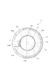
- the longitudinal cross-sectional view of the oil measurement cell which concerns on one Embodiment of this invention.
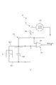
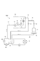
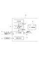
- the functional block diagram of the control apparatus of the specific resistance measuring apparatus of the embodiment. The schematic diagram which shows the specific resistance measurement circuit of the embodiment.
- Specific resistance measuring device 2 Oil measuring cell (liquid sample measuring cell) 21 ... External electrode 22 ... Internal electrode 4 ... Specific resistance measuring unit C ... Specific resistance measuring circuit Ca ... Reference resistance Cb ... AC power supply OP ... Operational amplifier CL1 ... External Wiring CL2 connected to electrode ... Wiring C1 connected to internal electrode ... Shield drive circuit Cd ... Floating capacitance
- the specific resistance measuring apparatus 100 uses the oil (liquid sample) in order to detect deterioration of hydraulic oil (hereinafter simply referred to as oil) used in a lubricating oil or a hydraulic device used in a bearing, a gear, or the like. ) Is continuously measured.
- this is a two-electrode type, and as shown in FIGS. 1 to 3, a cylindrical internal electrode 22 is arranged inside a cylindrical external electrode 21, and these electrodes 21 are arranged.
- 22 is an oil measuring cell (corresponding to the liquid sample measuring cell of the present invention) 2 and a heater 3 provided on the external electrode 21 for heating the oil contained in the cell space S.
- a specific resistance measuring unit 4 that measures the specific resistance of the oil by detecting a voltage generated between the external electrode 21 and the internal electrode 22, and a heating temperature setting signal that receives a heating temperature setting signal that indicates the heating temperature of the oil
- the receiving part 5 and the heater control part 6 which controls the heater 3 based on the heating temperature setting signal are provided.
- the specific resistance measuring unit 4, the heating temperature setting signal receiving unit 5, and the heater control unit 6 are configured by a control device 10.
- each part will be described.
- the oil measurement cell 2 includes a cylindrical external electrode 21, a cylindrical internal electrode 22 that is inserted into the external electrode 21 and provided coaxially with the external electrode 21, An insulating member that fixes the electrode 21 and the internal electrode 22 to each other, closes both end openings of the external electrode 21, and forms a cell space S that contains oil between the inner surface of the external electrode 21 and the outer surface of the internal electrode 22. 23.
- the oil measurement cell 2 fixes the internal electrode 22 to the external electrode 21 at both axial ends, and fixes and fixes the opposing distance between the inner surface of the external electrode 21 and the outer surface of the internal electrode 22. And an insulating member 23 that forms an oil measurement space (cell space) S.
- the external electrode 21 and the internal electrode 22 of the present embodiment are made of stainless steel.
- the insulating member 23 is configured to fix the internal electrode 22 to the external electrode 21 with a double-sided structure and suppress the vibration of the internal electrode 22 from external vibration. Further, the insulating member 23 closes both end openings of the external electrode 21 to form a cell space S in which oil is accommodated between the inner surface of the outer electrode 21 and the outer surface of the inner electrode 22. Both ends in the axial direction of the cell space S are closed by the insulating member 23, and the cell space S becomes a substantially cylindrical space.
- the insulating member 23 has an annular shape, and the axial end of the internal electrode 22 is inserted into the opening via a seal member 24 such as an O-ring, and the axial end surface of the insulating member 23 is the external electrode 21. It is closely attached to the axial end face via a seal member 25 such as an O-ring.
- the insulating member 23 is fixed to the external electrode 21 by an annular fixing member 26.
- the clearance gap between the inner surface of the external electrode 21 and the outer surface of the internal electrode 22 can be made small, and a cell constant can be made about 1/10 smaller than before.
- the cell constant of the oil measurement cell 2 can be set to 0.001 / cm, for example.
- an oil introduction path L1 for introducing oil into the cell space S is formed in the internal electrode 22 on one axial end side, and the internal electrode 22 on the other axial end side
- An oil lead-out path L2 for leading oil from the cell space S is formed.
- External pipes H1 and H2 made of an insulating material such as PFA are connected to the inlet port P1 of the oil inlet path L1 and the outlet port P2 of the oil outlet path L2. In this way, by configuring the external pipes H1 and H2 with insulating pipes, the noise current can be reduced by being insulated from the outside and can be measured stably.
- These external pipes H1 and H2 are connected to bearings, gears, or a hydraulic device or the like directly or via other connecting pipes.
- the external pipe H1 is provided with a flow meter (not shown).
- the oil introduction path L1 is formed at one end of the internal electrode 22 in the axial direction, and the oil introduction path L1 has a plurality of oil introduction ports L1a communicating with one end of the cell space S in the axial direction.
- the oil outlet passage L2 is formed at the other axial end portion of the internal electrode 22, and the oil outlet passage L2 has a plurality of oil outlet ports L2a communicating with the other axial end portion of the cell space S. Yes. Note that one end and the other end in the axial direction of the internal electrode 22 are a portion extending outward from the external electrode 21 or a portion in the vicinity thereof.
- the oil introduction path L1 and the oil lead-out path L2 are formed in the insulating member 23, there is no need to provide the introduction port P1 and the lead-out port P2 in the external electrode 21 and the internal electrode 22, and the external electrode 21 and The facing area of the internal electrode 22 can be increased, and the cell constant can be reduced.
- the oil introduction path L1 has a plurality of oil introduction ports L1a, the oil can be evenly distributed in the circumferential direction in the cell space S, and the oil outlet path L2 has a plurality of oil outlets L2a. Further, oil can be prevented from staying inside the cell space S and can be efficiently derived. Therefore, the specific resistance of oil can be measured with high accuracy.
- the oil inlet L1a is formed at the lowermost end of the cell space S
- the oil outlet L2a is formed at the uppermost end of the cell space S. That is, the oil introduction port L1a is opened at the lower edge portion on the outer surface of the internal electrode 22 forming the cell space S.
- the oil outlet L2a is open at the upper edge portion on the outer surface of the internal electrode 22 forming the cell space S.
- the plurality of oil inlets L1a and the plurality of oil outlets L2a are formed at equal intervals in the circumferential direction of the cell space S.
- the cell space S can be uniformly filled with oil, and the oil can be uniformly discharged from the cell space S in the circumferential direction, so that the accumulation of bubbles can be further prevented.
- the heater 3 for heating the oil stored in the cell space S is provided on a part of the outer peripheral surface 21a of the external electrode 21.
- the heater 3 is, for example, a sheet-like member configured by incorporating a heating resistor in a flexible member such as silicon.
- the heater 3 is provided in close contact with the outer peripheral surface 21 a of the external electrode 21.
- the heater 3 is provided corresponding to substantially the entire inner cell space S in the axial direction, and is provided in a part of the outer peripheral surface 21a in the circumferential direction. Is provided so as to be exposed to the outside. This externally exposed portion 21b functions as a heat radiating portion.
- the external electrode 21 is made of stainless steel and has excellent thermal conductivity, the entire cell space S can be heated by the partially provided heater 3, and the external exposed portion 21 b Cooling of the cell space S can also be facilitated.
- the current flowing through the heater 3 is controlled by a heater control unit 6 of the control device 10 described later.
- a temperature sensor 7 for detecting the temperature of the external electrode 21 is provided in a portion where the heater 3 is not provided on the outer peripheral surface 21a of the external electrode 21, that is, in the externally exposed portion 21b.
- the temperature sensor 7 is provided on the bottom surface of the recess 21M formed in the externally exposed portion 21b. Thereby, the temperature of the external electrode 21 can be detected with high accuracy.
- the temperature sensor 7 is provided on the external electrode 21 at the axial center. The detection signal obtained by the temperature sensor 7 is acquired by the control device 10.
- the control device 10 controls the heater 3 using the temperature detected by the temperature sensor 7 so that the temperature of the external electrode 21 is constant, and measures the specific resistance of the oil flowing through the oil measuring cell 2. is there. Specifically, the control device 10 functions as the specific resistance measuring unit 4, the heating temperature setting signal receiving unit 5, the heater control unit 6, and the like.
- the control device 10 is constituted by a digital or analog electric circuit having a CPU, a memory, an A / D converter, a D / A converter, etc., and may be a dedicated device or a part thereof. Alternatively, a general-purpose computer such as a personal computer may be used for all. Further, it may be configured such that the functions of the respective units are achieved by using only an analog circuit without using a CPU, and need not be physically integrated, but includes a plurality of devices connected to each other by wire or wirelessly. It may be a thing.
- the specific resistance measuring unit 4 measures the specific resistance of the oil by detecting the voltage generated between the external electrode 21 and the internal electrode 22.
- the specific resistance measuring unit 4 has a specific resistance measuring circuit C shown in FIG.
- This specific resistance measurement circuit C applies a reference resistance Ca (R 1 ) having a known resistance value connected in series to the internal electrode 22, and an alternating voltage (V 1 ) to the pair of electrodes 21, 22 and the reference resistance Ca.
- AC power source Cb a detection unit Cc that detects an inter-electrode voltage (V 2 ) generated between the pair of electrodes 21 and 22, and an oil specific resistance (R 2 ) using an output voltage from the detection unit Cc.
- a signal processing unit (not shown) for calculation.
- the detection unit Cc of the present embodiment is configured by an operational amplifier OP that performs impedance conversion and outputs an interelectrode voltage (V 2 ).
- the AC power source Cb is connected between the external electrode 21 and the internal electrode 22 with a rectangular wave AC voltage having an amplitude of 1 V to 42 V and a frequency of 0.5 Hz to 30 Hz. V 1 ) is applied.
- the frequency of the rectangular wave AC voltage is more preferably 2 Hz or more for securing the response speed, and more preferably 15 Hz or less for securing the measurement accuracy.
- the amplitude of the rectangular wave AC voltage is more preferably 15 V or less because an existing circuit element is used.
- the signal processing unit uses the stable output voltage to obtain a specific resistance at a timing when the output voltage output from the detection unit Cc is stabilized with the application of the rectangular wave AC voltage (V 1 ) by the AC power source Cb.
- the signal processing unit calculates the specific resistance using a stable output voltage. (1) After a predetermined time has passed since the output voltage in the latter half of the rectangular wave, that is, the positive / negative of the AC voltage is switched (in other words, For example, a configuration for calculating the specific resistance using the output voltage acquired immediately before switching between positive and negative of the AC voltage, or (2) determining whether the output voltage is stable by calculating the fluctuation amount, A configuration in which the specific resistance is calculated using the output voltage when it is determined to be stable can be considered.
- the specific resistance measuring circuit C is provided with a shield drive circuit C1 in which the potential difference of the stray capacitance Cd formed between the wiring CL1 connected to the external electrode 21 and the wiring CL2 connected to the internal electrode 22 is zero. It has been.
- the shield drive circuit C1 is configured using an operational amplifier OP that constitutes the detection unit Cc.
- the time constant of the specific resistance measuring circuit C can be reduced, and the time until the interelectrode voltage (V 2 ) is stabilized can be shortened. Therefore, the specific resistance of oil can be measured with high accuracy, and oil deterioration can be detected with high accuracy.
- the AC power source Cb can measure the specific resistance of the oil between the external electrode 21 and the internal electrode 22 and can prevent the deterioration of the oil due to the measurement.
- a wave alternating voltage (V 1 ) is applied.
- V 1 A wave alternating voltage
- the rectangular wave AC voltage is applied, it is possible to suppress the formation of the electric double layer at the boundary between the electrodes 21 and 22 and the oil, and to continuously measure the specific resistance of the oil.
- a voltage having a predetermined amplitude is applied, deterioration due to measurement such as alteration of oil during measurement can be prevented.
- the signal processing unit uses the stable output voltage to set the specific resistance at a timing when the output voltage output from the detection unit Cc is stabilized with the application of the rectangular wave AC voltage (V 1 ) by the AC power source Cb. It is comprised so that it may calculate.
- the signal processing unit calculates the specific resistance using a stable output voltage.
- the output voltage in the second half of the rectangular wave that is, after the lapse of a predetermined time after the positive / negative of the AC voltage is switched (in other words, for example, a configuration for calculating the specific resistance using the output voltage acquired immediately before switching between positive and negative of the AC voltage, or (2) determining whether the output voltage is stable by calculating the fluctuation amount, A configuration in which the specific resistance is calculated using the output voltage when it is determined to be stable can be considered.
- the heating temperature setting signal receiving unit 5 receives a heating temperature setting signal indicating a heating temperature suitable for measuring the specific resistance of the oil stored in the oil measuring cell 2.
- This heating temperature setting signal is generated when the user inputs using a keyboard, a mouse, a touch panel, a temperature setting button or other input means or a communication system of the oil management system 100Z described later.
- the heating temperature setting signal reception part 5 transmits the received heating temperature setting signal to the heater control part 6 described later.
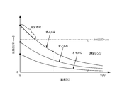
- the specific resistance of the oil decreases with time, that is, with deterioration (oxidation) of the oil.
- the specific resistance varies depending on the type and temperature. The specific resistance of oil is greatest when not in use. For this reason, the heating temperature of various oils is set so that the specific resistance when the various oils are not used is within the measurement range of the oil measurement cell 2.
- the heater control unit 6 acquires a heating temperature setting signal from the heating temperature setting signal receiving unit 5 and also acquires a detection signal from a temperature sensor 7 provided in the oil measurement cell 2 and measures the temperature (measurement) indicated by the detection signal. Temperature) and the temperature (set temperature) indicated by the heating temperature setting signal are compared, and the current flowing through the heater 3 is controlled so that the temperature measured by the temperature sensor 7 becomes the set temperature.
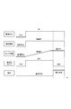
- the user turns on the specific resistance measuring apparatus 100. And a user sets the heating temperature suitable for the specific resistance measurement of the oil which is a measuring object by an input means.
- a heating temperature setting signal indicating the heating temperature set here is acquired by the heating temperature signal setting reception unit 5 and transmitted to the heater control unit 6.
- the heater control unit 6 acquires a heating temperature setting signal and starts temperature control of the heater 3.
- the oil measuring cell 2 is warmed up by the heater 3.
- the measured temperature obtained by the temperature sensor 7 increases toward a desired heating temperature.
- the specific resistance measuring unit 4 starts measuring the specific resistance of the oil.
- the warm-up lamp provided in the control device 10 is lit until the oil measurement cell 2 reaches a certain temperature after the heater control unit 6 starts the temperature control of the heater 3, and the user prepares for measurement. It is set as the structure which alert
- the timing of starting the specific resistance measurement by the specific resistance measuring unit 4 may be, for example, the following (1), (2), and (3).
- a user who has confirmed that the warm-up lamp has been switched from lighting to extinguishing operates a measurement start switch or the like provided separately to transmit a measurement start signal to the specific resistance measuring unit 4 Is done. And the specific resistance measurement part 4 starts a specific resistance measurement, when the said measurement start signal is acquired.
- the heater control unit 6 is configured to transmit a determination signal to the specific resistance measurement unit 4 when it is determined that the measured temperature of the temperature sensor 7 is the same as the set temperature. Then, the specific resistance measurement unit 4 starts the specific resistance measurement when the determination signal is acquired.
- the specific resistance measuring unit 4 acquires the heating temperature setting signal from the heating temperature setting signal receiving unit 5 or the heater control unit 6, and also acquires the detection signal from the temperature sensor 7, and the temperature indicated by the detection signal ( The measurement temperature) is compared with the temperature (set temperature) indicated by the heating temperature setting signal.
- the start of specific resistance measurement or the validity determination of acquired data may be performed by a computer or the like that has received a signal via an oil management system 100Z described later.
- an oil management system 100Z using the specific resistance measuring apparatus 100 of the present embodiment will be described with reference to FIG. Since the target device X managed by the specific resistance measuring apparatus 100 has a different relationship between the degree of deterioration, the specific resistance value, and the temperature depending on the type of the used liquid such as lubricating oil, the specific resistance measurement of the used liquid of the target device X is performed in advance. It is desirable to confirm the behavior in the apparatus 100 and use a working solution whose behavior has been confirmed.
- the oil management system 100Z includes a transmission system (not shown) that automatically transmits the specific resistance value and temperature obtained by the specific resistance measurement device 100 to a management device (user terminal) on the manager side via a communication line.
- the oil management can be performed over time by acquiring the specific resistance value and the temperature as signals.
- the management device In addition to the signal from the specific resistance measuring device 100, the management device also receives a signal from a measuring device that measures other measurement target items such as moisture and light transmittance. Therefore, the used liquid can be managed.
- the oil management system 100Z includes an oil supply pipe 11 (corresponding to the external pipe H1 described above) for supplying the used liquid from the used liquid tank X1 of the target device X to the oil measuring cell 2 of the specific resistance measuring apparatus 100.
- An oil drain pipe 12 (corresponding to the above-described external pipe H2) for returning the oil from the oil measuring cell 2 back to the working liquid tank X1 is provided.
- the use liquid tank X1 is provided with a purification line X2 for purifying the oil stored in the use liquid tank X1, and the purification line X2 is used for circulating oil through the line X2.
- a pump X21 and a filter X22 for removing foreign matters such as contaminants and wear powder contained in the oil are provided.
- the oil collection part by the oil introduction port of the oil supply pipe 11 is the used liquid tank X1, more specifically, downstream of the filter X22 in the purification line X2.
- the use liquid purified by the filter X22 can be supplied to the oil measurement cell 2.
- the oil introduction port is provided in a portion in contact with the use liquid in the use liquid tank X1.
- the oil supply pipe 11 is provided with a supply pump 13 for supplying oil collected by the oil introduction port to the oil measurement cell 2.
- the supply pump 13 may be provided in the oil drain pipe 12.
- the foreign matter removing mechanism 14 is a collection unit made of a filter, a magnet, or the like that collects impurities or wear powder contained in the oil. And this collection unit 14 is made detachable with respect to the oil supply pipe 11, and performs strict oil management by analyzing the collected matter collected by the collected collection unit 14 It is configured to be able to.
- the foreign matter removing mechanism 14 of the present embodiment is a filter, and pressure sensors 15 and 16 are provided on the upstream side and the downstream side of the filter 14.
- the pressure from the pressure sensors 15 and 16 is acquired as a signal and
- the differential pressure is used so that filter management such as clogging of the filter 14 can be performed together with oil management.
- the oil drain pipe 12 is provided with a sampling line 16, and when the specific resistance value obtained by the specific resistance measuring device 100 becomes an abnormal value, the use liquid indicating the abnormal specific resistance value is sampled.
- the container 17 can be collected. Furthermore, when this system is operated in a portable manner, a number of devices are measured with one system per day to obtain quick results, and detailed analysis using actual samples for each device and results. Therefore, the sampling mechanism functions extremely effectively.
- the sampling line 16 is a sampling pipe provided in the middle of the oil drain pipe 12, and a sampling container 17 is provided at the outlet of the sampling pipe 16.
- a switching valve 18 is provided on the downstream side of the branch point in the oil drain pipe 12 and the sampling pipe 16 for switching the pipe through which the used liquid flows.
- This switching valve 18 may be an electromagnetic valve that can be switched automatically, or a manual valve that can be switched manually.
- sampling container 17 is detachably attached to the sampling tube 16, and the abnormal use liquid stored in the sampling container 17 is analyzed by an analyzer such as an element analyzer.
- an oil pan 19 is provided below the sampling container 17 for collecting the used liquid overflowing from the sampling container 17, and the collected used liquid is used for the used liquid.
- a return pipe 20 for returning to the tank X1 is provided.
- the so-called both-end support in which the insulating member 23 fixes the internal electrode 22 to the external electrode 21 at both axial ends of the oil measurement cell 2. Since the opposing distance between the inner surface of the external electrode 21 and the outer surface of the internal electrode 22 is fixed by the insulating member 23, the internal electrode 22 is shaken with respect to the external electrode 21 by vibration from the outside. It is possible to suppress the variation in the facing distance. As a result, a structure in which the opposing distance between the inner surface of the external electrode 21 and the outer surface of the internal electrode 22 is reduced or the length dimension of the external electrode 21 and the internal electrode 22 is increased to reduce the cell constant and to reduce the cell constant. Measurement impediments can be prevented and measurement errors can be reduced. Therefore, the measurement accuracy of the electrical characteristics of the oil can be improved, and the oil deterioration can be detected with high accuracy.
- the temperature of the oil accommodated in the cell space S is adjusted to a predetermined heating temperature, it can be set to a temperature suitable for measuring the specific resistance of each oil, and the ratio of various oils The resistance can be made measurable.
- the temperature of the oil stored in the cell space S is controlled to be constant, measurement errors due to temperature fluctuations of the oil can be reduced without necessarily relying on temperature compensation, and the specific resistance of the oil can be measured with high accuracy. be able to. Therefore, it is possible to accurately detect oil deterioration of various oils.
- particularly high-viscosity oil since the viscosity is lowered by heating, the oil can be easily circulated through the oil measurement cell 2. When combined with the cell structure of this embodiment, the bubble pool is reduced. This can be further prevented.
- the temperature of the oil accommodated in the cell space S is adjusted to a predetermined heating temperature.
- the temperature can be set to a temperature suitable for resistance measurement, and the specific resistance of various oils can be measured.
- the temperature of the oil stored in the cell space S is controlled to be constant, measurement errors due to temperature fluctuations of the oil can be reduced without necessarily relying on temperature compensation, and the specific resistance of the oil can be measured with high accuracy. be able to. Therefore, it is possible to accurately detect oil deterioration of various oils.
- particularly high-viscosity oil since the viscosity is lowered by heating, the oil can be easily distributed to the oil measurement cell 2.
- the specific resistance measuring apparatus 100 may further include a deterioration determination unit.
- the deterioration determination unit is configured by the control device 10.
- the deterioration determination unit performs deterioration determination by comparing the specific resistance obtained by the specific resistance measurement unit 4 with a predetermined threshold (reference specific resistance).
- the reference specific resistance is set for each of various oils.
- the user may be able to set and input the threshold, or threshold data indicating threshold values set for each of the various oils may be stored in the memory. The user may be able to select it.
- the deterioration determination may be performed based on the relationship with the initial value (specific resistance) of the measured oil, for example, the ratio to the initial value.
- the deterioration determination unit outputs a deterioration determination signal to the notification unit control unit provided in the control device 10 when the calculated specific resistance is lower than the threshold value.
- the notifying unit control unit controls a notifying unit such as a lamp or a display provided in the control device 10 to notify the user of oil deterioration.
- the configuration is such that the user sets the heating temperature, but the heating temperature may be automatically set on the control device 10 side when the user inputs the oil type.
- the control device 10 includes a data storage unit 8 that stores heating temperature setting data indicating the heating temperature set for each type of oil, and the oil stored in the oil measurement cell 2. It is conceivable to include an oil selection signal receiving unit 9 that receives an oil selection signal indicating the type.
- the data storage unit 8 stores heating temperature setting data indicating the heating temperature set for each type of oil.
- the heating temperature setting data indicates, for example, the heating temperature set so that the specific resistance of each oil when not in use is within the measurement range of the oil measurement cell 2.
- the heating temperature setting data is stored in advance in the data storage unit 8 by the user.
- the oil selection signal receiving unit 9 receives an oil selection signal indicating the type of oil to be measured that is stored in the oil measurement cell 2.
- the oil selection signal is generated when the user inputs using an input means such as a keyboard, a mouse, a touch panel, an oil setting button, or the communication system of the oil management system 100Z.
- the oil selection signal receiving unit 9 transmits the received oil selection signal to the heater control unit 6.
- the heater control unit 6 acquires an oil selection signal from the oil selection signal receiving unit 9, and based on the oil selection signal and the heating temperature setting data stored in the data storage unit 8, the heating temperature of the heater 3 (set temperature) ) Is set. And the heater control part 6 acquires a detection signal from the temperature sensor 7 provided in the oil measurement cell 2, and compares the temperature (measurement temperature) which the detection signal shows with the set heating temperature (setting temperature). Then, the current value flowing through the heater 3 is controlled so that the temperature indicated by the detection signal of the temperature sensor 7 becomes the set heating temperature.
- the user can adjust the temperature to a temperature suitable for measuring the specific resistance of the oil only by inputting the type of the oil.
- Each temperature can be set to a temperature suitable for measuring the specific resistance of the oil, and the specific resistance of various oils can be measured.
- the specific resistance measuring unit 4 may be configured without the shield drive circuit C1.
- a specific resistance measuring circuit C is provided, and the specific resistance of oil can be continuously measured between the external electrode 21 and the internal electrode 22, and the oil deterioration due to the measurement can be prevented.
- a rectangular wave AC voltage (V 1 ) having a predetermined amplitude and a predetermined frequency that can be prevented may be applied.
- V 1 rectangular wave AC voltage
- the rectangular wave AC voltage since the rectangular wave AC voltage is applied, it is possible to suppress the formation of the electric double layer at the boundary between the electrodes 21 and 22 and the oil, and to continuously measure the specific resistance of the oil.
- a voltage having a predetermined amplitude is applied, deterioration due to measurement such as alteration of oil during measurement can be prevented.
- the measurement range by the specific resistance measuring unit 4 is 0 to 200 G ⁇ ⁇ cm.
- the heating temperature is set before the start of the temperature control of the heater.
- the setting is set before (for example, before the start of the temperature control) after the start of the temperature control of the heater or during the specific resistance measurement. You may comprise so that temperature can be changed.
- the upper limit value and the lower limit value of the heating temperature can be set, and the temperature of the oil measurement cell 2 is controlled between the upper limit value and the lower limit value of the heating temperature.
- You may comprise as follows.
- the specific resistance calculated by the specific resistance measurement unit may be configured to be temperature compensated using the detected temperature obtained by the temperature sensor.
- the heater of the above embodiment may be constituted by an external electrode or an internal electrode. That is, the function as a heater may be exhibited by energizing and heating the electrode by passing a current through the external electrode or the internal electrode. At this time, by causing an electric current to flow through the internal electrode and causing the internal electrode to function as a heater, the liquid sample can be heated quickly, and measurement can be performed with higher accuracy.
- oil introduction path L1 and the oil lead-out path L2 of the above embodiment are provided in the internal electrode 22, but may be provided in the insulating member 23.
- the oil measurement cell 2 and the control device 10 may be accommodated in one casing and unitized.
- the casing has a supply port to which piping for supplying oil such as an external bearing and a hydraulic device is connected to the oil measurement cell, and an external bearing for discharging the measured oil from the oil measurement cell to the outside. It is conceivable to provide a discharge port to which a pipe for returning measured oil is connected to a hydraulic device or the like.
- the specific resistance is calculated by detecting the voltage (V 2 ) between the external electrode 21 and the internal electrode 22, but the specific resistance is calculated by detecting the voltage applied to the reference resistor Ca. You may make it do. In this case, detecting the resistance value R 1 of the reference resistor Ca with differential circuits.
- the specific resistance measurement device that measures the specific resistance of oil has been described as the oil analysis device.
- the oil analysis device has other electrical characteristics such as an oxidation-reduction potential or a dielectric constant of oil. May be used.
- the oil measurement cell has an oil heating function and the external electrode is provided with a heater, but the oil measurement cell may have no oil heating function. In this case, it can be considered that the external electrode is not provided with a heater.
- the heater of the above embodiment may be constituted by an external electrode or an internal electrode. That is, the function as a heater may be exhibited by energizing and heating the electrode by passing a current through the external electrode or the internal electrode. At this time, by causing an electric current to flow through the internal electrode and causing the internal electrode to function as a heater, the liquid sample can be heated quickly, and measurement can be performed with higher accuracy.
- the specific resistance of a liquid sample can be measured continuously and accurately, and deterioration such as alteration of the liquid sample accompanying measurement can be prevented.
Landscapes
- Chemical & Material Sciences (AREA)
- Life Sciences & Earth Sciences (AREA)
- Health & Medical Sciences (AREA)
- Chemical Kinetics & Catalysis (AREA)
- Physics & Mathematics (AREA)
- Pathology (AREA)
- Immunology (AREA)
- General Physics & Mathematics (AREA)
- Analytical Chemistry (AREA)
- Biochemistry (AREA)
- General Health & Medical Sciences (AREA)
- Electrochemistry (AREA)
- Engineering & Computer Science (AREA)
- Oil, Petroleum & Natural Gas (AREA)
- Medicinal Chemistry (AREA)
- Food Science & Technology (AREA)
- General Chemical & Material Sciences (AREA)
- Investigating Or Analyzing Materials By The Use Of Electric Means (AREA)
- Measurement Of Resistance Or Impedance (AREA)
Abstract
本発明は、液体試料の比抵抗を連続して精度良く測定できるとともに、測定に伴う液体試料の変質等の劣化を防ぐものであり、液体試料の劣化を検知するために比抵抗を測定する比抵抗測定回路Cであって、外部電極21及び内部電極22の間に生じる電圧を検出することによって、液体試料の比抵抗を算出するものであり、外部電極21及び内部電極22の間に、振幅が1V~42Vで周波数が0.5Hz~30Hzの矩形波交流電圧を印加する。
Description
本発明は、例えば潤滑油等の液体試料の比抵抗を測定する比抵抗測定装置、当該比抵抗測定装置に用いられる比抵抗測定回路及び液体試料測定セル、前記比抵抗測定装置を用いた液体使用管理方法及び液体試料管理システムに関するものである。
従来、絶縁性の液体であるIPA(イソプロピルアルコール)の比抵抗を測定するものとして、特許文献1に示すものが考えられている。この比抵抗測定装置は、外部電極及び内部電極に交流電圧を印加して、外部電極及び内部電極の間に位置するIPAの比抵抗を測定するものである。
ここで、IPAの比抵抗は1000MΩ・cm程度であり、外部電極及び内部電極に印加する交流電圧としては、振幅が2V程度で周波数が100Hzのものを用いている。なお、IPAの他にも、純水等の比抵抗も同様の交流電圧を用いて測定することが一般的である。
一方、潤滑油等のオイルの劣化を検知するために当該オイルの比抵抗を測定するものとして、前記比抵抗測定装置を用いることが考えられている。
しかしながら、オイルの比抵抗は、IPAの比抵抗に比べて数十倍~数百倍大きいため、外部電極及び内部電極を有する測定回路に流れる電流が小さいため測定が難しく、また測定回路の浮遊容量によって、交流電圧による応答が悪くなってしまう。そうすると、周波数100Hzの交流電圧を印加した場合には、測定回路から出力される信号(例えば出力電圧)が安定する前に交流電圧の正負が切り替わってしまうため、オイルの比抵抗測定を精度良く行うことができないという問題がある。
また、オイルの比抵抗を測定するために、外部電極及び内部電極に印加する電圧を例えば1000V等の高電圧にして、検出電流を大きくすることが考えられる。なお、従来のオイルの比抵抗測定においては、高電圧を印加することが一般的である。
しかしながら、オイルに例えば1000Vといった高電圧を印加すると、オイルが酸化して変質してしまい、測定によってオイルの劣化を招いてしまうという問題がある。
そこで本発明は、上記問題点を一挙に解決するためになされたものであり、液体試料の比抵抗を連続して精度良く測定できるとともに、測定に伴う液体試料の変質等の劣化を防ぐことをその主たる所期課題とするものである。
すなわち本発明に係る比抵抗測定回路は、液体試料劣化を検知するために比抵抗を測定する比抵抗測定回路であって、一対の電極の間に生じる電圧を検出することによって、当該一対の電極間にある液体試料の比抵抗を測定するものであり、前記一対の電極の間に、振幅が1V~42Vで周波数が0.5Hz~30Hzの矩形波交流電圧を印加することを特徴とする。ここで、液体試料には、潤滑油、潤滑用液状有機媒体、錆止め油、放電加工油、液圧作動媒体液、食用油等のオイル類、熱媒体液、熱処理液、ワニス・顔料・農薬等希釈用炭化水素系溶媒、洗浄用炭化水素系溶媒、流動性を有するグリス類、IPA(イソプロピルアルコール)等のアルコールなどが含まれる。
このようなものであれば、上記のような矩形波交流電圧を印加しているので、電極及び液体試料の境界において電気二重層が形成されることを抑制し、液体試料の比抵抗を連続測定することができる。また、1V~42Vの電圧を印加することから測定中の液体試料の変質等の測定による劣化を防ぐことができる。ここで、1V~42Vの交流電圧としていることから、電源を安価に構成することができるとともに、感電した場合であっても人体への危険性を低減することができる。さらに、周波数が0.5Hz~30Hzであるため、交流電圧の切り替え前において測定回路から出力される信号を安定させることができるので、液体試料の比抵抗を精度良く測定することができ、液体試料の劣化を精度良く検知することができる。この液体試料測定セルは、IPAの比抵抗に比べて数十倍~数百倍大きいオイル等の液体試料の比抵抗を測定できるだけでなく、IPA等の比抵抗が10GΩ・cm未満の液体試料の比抵抗も当然に測定できる。
なお、外部電極及び内部電極に直流電圧を印加した場合には、電極と液体試料の境界の電気二重層に電荷が溜まってしまい、次第に電気二重層の電位が増加するに伴って電極間の電位勾配が低下し、イオンの移動が低下して、比抵抗が上昇する。これにより、液体試料の比抵抗を連続測定する場合に直流電圧を用いると、液体試料の比抵抗を精度良く測定することが難しい。
前記一対の電極に接続される配線の間に形成される浮遊容量の電位差をゼロとする、オペアンプを用いたシールドドライブ回路を有することが望ましい。これならば、一対の電極に接続される配線の間に形成される浮遊容量を測定回路から切り離すことができ、液体試料の比抵抗を示す信号の応答を速くすることができるとともに、その抽出を容易にすることができる。したがって、液体試料の比抵抗を精度良く測定することができ、液体試料の劣化を精度良く検知することができる。
また、前記IPAの比抵抗は10GΩ・cm未満であり、外部電極及び内部電極により規定されるセル定数は0.01/cm以上である。なお、セル定数は、外部電極の内面及び内部電極の外面の対向面積をS(cm2)、外部電極の内面及び内部電極の外面の対向距離をL(cm)としたとき、L/Sで表わされる値である。
また、オイルの比抵抗は、IPAの比抵抗に比べて数十倍~数百倍大きいため、前記比抵抗測定装置のセル定数(0.01/cm)では、オイルの比抵抗が測定レンジを超えてしまう場合がある。このため、外部電極及び内部電極により規定されるセル定数を小さくすることで、測定レンジを広くする必要がある。
従来のセル構造は、円筒状の外部電極に円柱状の内部電極を挿入して、内部電極の軸方向一端部を絶縁部材で保持する片持ち構造である。このセル構造においてセル定数(S/L)を小さくするためには、外部電極の内面及び内部電極の外面の対向距離を小さくすることが考えられる。また、外部電極の内面及び内部電極の外面の対向面積を大きくする、つまり、外部電極及び内部電極の長さ寸法を大きくする等が考えられる。
しかしながら、片持ち構造のセル構造において、上述したように、外部電極の内面及び内部電極の外面の対向距離を小さくする、又は、外部電極及び内部電極の長さ寸法を大きくする等の構造を採用すると、外部からの振動によって、内部電極の自由端がぶれやすく、その結果、内部電極及び外部電極が接触して測定不可となり、或いは、内部電極の外面及び外部電極の内面の対向距離が変化して測定誤差を招いてしまう。
そこで本発明は、液体試料測定セルのセル定数を小さくするとともに、振動による内部電極の軸ぶれを低減して、測定精度を向上させること課題とするものである。
すなわち、本発明に係る液体試料測定セルは、液体試料の比抵抗を測定するための液体試料測定セルであって、円筒状の外部電極と、前記外部電極に挿入されて前記外部電極と同軸状に設けられる円柱状の内部電極と、軸方向両端部において前記外部電極に対して前記内部電極を固定し、前記外部電極の内面及び前記内部電極の外面の対向距離を固定することにより測定空間を形成する絶縁部材とを備えていることを特徴とする。ここで、液体試料には、潤滑油、潤滑用液状有機媒体、錆止め油、放電加工油、液圧作動媒体液、食用油等のオイル類、熱媒体液、熱処理液、ワニス・顔料・農薬等希釈用炭化水素系溶媒、洗浄用炭化水素系溶媒、流動性を有するグリス類、IPA(イソプロピルアルコール)等のアルコールなどが含まれる。
このような液体試料測定セルであれば、軸方向両端部において、絶縁部材が外部電極に対して内部電極を固定する所謂両持ち構造であり、当該絶縁部材により、外部電極の内面及び内部電極の外面の間の対向距離が固定されているので、外部からの振動により、内部電極が外部電極に対してぶれにくくして、対向距離の変動を抑制することができる。これにより、外部電極の内面及び内部電極の外面の対向距離を小さくする構造又は外部電極及び内部電極の長さ寸法を大きくする構造を採用してセル定数を小さくしつつ、振動による測定不可を防ぎ、測定誤差を低減することができる。したがって、液体試料の比抵抗を測定精度を向上させることができ、液体試料劣化を精度良く検知することができる。この液体試料測定セルは、IPAの比抵抗に比べて数十倍~数百倍大きいオイル等の液体試料の比抵抗を測定できるだけでなく、IPA等の比抵抗が10GΩ・cm未満の液体試料の比抵抗も当然に測定できる。
前記絶縁部材が、前記外部電極の軸方向両端部の開口を閉塞することにより、前記測定空間の軸方向両端部が閉じされたものであり、軸方向一端部における内部電極又は絶縁部材に、前記測定空間に液体試料を導入するための液体試料導入路が形成されており、軸方向他端部における内部電極又は絶縁部材に、前記測定空間から液体試料を導出するための液体試料導出路が形成されていることが望ましい。これならば、内部電極又は絶縁部材に、液体試料導入路及び液体試料導出路を形成しているので、外部電極に導入ポート及び導出ポートを設ける必要が無く、外部電極及び内部電極の対向面積を大きくすることができる。また、外部電極に導入ポート及び導出ポートを形成する場合には、対向面積を大きくする観点から1箇所ずつ設けることになるが、そうすると、液体試料導入口及び液体試料導出口が1箇所ずつになるため、液体試料の滞留が生じ易く、気泡が溜まり易い。
前記液体試料導入路が、前記測定空間に連通する複数の液体試料導入口を有するものであり、前記液体試料導出路が、前記測定空間に連通する複数の液体試料導出口を有するものであることが望ましい。これならば、液体試料導入路が複数の液体試料導入口を有するため、測定空間における周方向に液体試料を万遍なく行き渡らせることができる。また、液体試料導出路が複数の液体試料導出口を有するため、測定空間内部での液体試料の滞留を防ぎ、効率良く導出することができる。
前記複数の液体試料導入口及び前記複数の液体試料導出口が、前記測定空間の周方向において等間隔に形成されていることが望ましい。これならば、測定空間に液体試料を均一に満たすことができるとともに、測定空間から液体試料を周方向において均一に排出することができ、気泡の溜まりを一層防ぐことができる。
前記液体試料導入口が、前記測定空間の最下端に形成されており、前記液体試料導出口が、前記測定空間の最上端に形成されていることが望ましい。これならば、測定空間の下端部及び上端部のデットスペースを可及的に小さくし、気泡の溜まりを防ぐことができる。
また、例えば軸受に用いられる潤滑油は、使用に伴って低分子化又は酸化してしまい、摩擦性能が低下して軸受の摩耗が大きくなってしまう。このため、前記潤滑油の交換又は補充時期の目安を図るべく、潤滑油の比抵抗を測定してその劣化を判断することが行われている。
従来の比抵抗測定装置としては、転がり軸受の外輪に固定されて、当該転がり軸受内の潤滑油の体積抵抗率、誘電率、又は誘電正接を温度補償することにより測定する測定器が考えられている。
しかしながら、上記のように測定器により得られた体積抵抗率等を温度補償するものでは、潤滑油の体積抵抗率等が測定器の測定レンジ内にある場合には適用できるが、潤滑油の体積抵抗率等が前記測定レンジ内に無い場合には、温度補償を行うことができないという問題がある。
特に、潤滑油は、その温度によって体積抵抗率等が異なるため、潤滑油の温度によっては、潤滑油の体積抵抗率等を測定することができない場合がある。
また、潤滑油の種類によってその劣化度合いが異なり、当該劣化度合いにより体積抵抗率が異なるため、潤滑油の劣化度合いによっては、測定することができない場合がある。つまり、潤滑油は、使用中及び使用後の比抵抗よりも未使用時の比抵抗が大きいため、新品の潤滑油の比抵抗が測定レンジ外となってしまう場合がある。
さらに、ある潤滑油においては、使用前の比抵抗及び使用後の比抵抗の両方が測定レンジ内にあり測定可能であっても、別の種類の潤滑油を測定する場合には、使用前の比抵抗が測定レンジ外となってしまい、当該別の種類の潤滑油を測定するためには、別の測定レンジを有する測定器を用いる必要がある等の問題がある。
そこで本発明は、種々のオイル等の液体試料毎にそれら液体試料の比抵抗の測定に適した温度となるように液体試料の温度を一定に制御して、種々の液体試料の比抵抗を測定可能にするとともに、温度補償に必ずしも頼ることなく液体試料の温度変動に伴う測定誤差を低減することを課題とするものである。
すなわち、本発明に係る比抵抗測定装置は、液体試料の比抵抗を測定する比抵抗測定装置であって、筒状をなす外部電極の内部に柱状をなす内部電極を配置して、それら電極の間にセル空間が形成された液体試料測定セルと、前記セル空間に収容された液体試料を加熱するヒータと、前記外部電極及び前記内部電極の間に生じる電圧を検出することによって、前記液体試料の比抵抗を測定する比抵抗測定部と、前記液体試料の加熱温度を示す加熱温度設定信号を受け付ける加熱温度設定信号受付部と、前記加熱温度設定信号に基づいて前記ヒータを制御するヒータ制御部とを備えることを特徴とする。ここで、液体試料には、潤滑油、潤滑用液状有機媒体、錆止め油、放電加工油、液圧作動媒体液、食用油等のオイル類、熱媒体液、熱処理液、ワニス・顔料・農薬等希釈用炭化水素系溶媒、洗浄用炭化水素系溶媒、流動性を有するグリス類、IPA(イソプロピルアルコール)等のアルコールなどが含まれる。
このようなものであれば、セル空間に収容される液体試料の温度を所定の加熱温度に温度調節するので、種々の液体試料毎にそれら液体試料の比抵抗の測定に適した温度とすることができ、種々の液体試料の比抵抗を測定可能にすることができる。また、セル空間に収容される液体試料の温度を一定に制御するので、温度補償に必ずしも頼ることなく液体試料の温度変動に伴う測定誤差を低減することができ、液体試料の比抵抗を精度良く測定することができる。したがって、種々の液体試料の劣化を精度よく検知することができる。さらに、特に粘性の高い液体試料の場合には、加熱することによって粘性が低下するため、液体試料を液体試料測定セルに流通し易くすることができる。
また本発明に係る比抵抗測定装置は、前記液体試料の種類毎に設定された加熱温度を示す加熱温度設定データを格納するデータ格納部と、前記液体試料測定セルに収容される液体試料の種類を示す液体試料選択信号を受け付ける液体試料選択信号受付部とを備え、前記ヒータ制御部が、前記加熱温度設定データ及び前記液体試料選択信号から得られる加熱温度設定信号に基づいて前記ヒータを制御することを特徴とする。
このようなものであれば、ユーザが液体試料の種類を入力するだけで、当該液体試料の比抵抗測定に好適な温度に温度調節することができるので、種々の液体試料毎にそれら液体試料の比抵抗の測定に適した温度とすることができ、種々の液体試料の比抵抗を測定可能にすることができる。また、セル空間に収容される液体試料の温度を一定に制御するので、温度補償に必ずしも頼ることなく液体試料の温度変動に伴う測定誤差を低減することができ、液体試料の比抵抗を精度良く測定することができる。したがって、種々の液体試料の劣化を精度よく検知することができる。さらに、特に粘性の高い液体試料の場合には、加熱することによって粘性が低下するため、オイルを液体試料測定セルに流通し易くすることができる。
前記ヒータが前記外部電極の外側周面の一部に設けられていることが望ましい。これならば、ヒータを外部電極の外側周面の一部に設けているので、外部電極を冷却する場合には、ヒータが設けられていない領域から放熱を促進することができ、好適に外部電極を冷却することができる。
前記ヒータが前記外部電極の外側周面における周方向の一部に設けられており、前記外部電極の温度を検出する温度センサが、前記外部電極の外側周面において前記ヒータが設けられていない部分に設けられていることが望ましい。これならば、ヒータ及び温度センサの個別に取り付け、取り外し等交換することができる。
このように構成した本発明によれば、測定に伴う液体試料の変質等の劣化を防ぎながら、液体試料の比抵抗を連続して精度良く測定できる。
100・・・比抵抗測定装置
2・・・オイル測定セル(液体試料測定セル)
21・・・外部電極
22・・・内部電極
4・・・比抵抗測定部
C・・・比抵抗測定回路
Ca・・・基準抵抗
Cb・・・交流電源
OP・・・オペアンプ
CL1・・・外部電極に接続される配線
CL2・・・内部電極に接続される配線
C1・・・シールドドライブ回路
Cd・・・浮遊容量
2・・・オイル測定セル(液体試料測定セル)
21・・・外部電極
22・・・内部電極
4・・・比抵抗測定部
C・・・比抵抗測定回路
Ca・・・基準抵抗
Cb・・・交流電源
OP・・・オペアンプ
CL1・・・外部電極に接続される配線
CL2・・・内部電極に接続される配線
C1・・・シールドドライブ回路
Cd・・・浮遊容量
以下に本発明に係る比抵抗測定装置の一実施形態について図面を参照して説明する。
本実施形態に係る比抵抗測定装置100は、軸受や歯車等に用いられる潤滑油又は油圧装置等に用いられる作動油(以下、単にオイルという。)の劣化を検知するために当該オイル(液体試料)の比抵抗(電気抵抗率)を連続測定するものである。
具体的にこのものは、2電極方式のものであり、図1~図3に示すように、円筒状をなす外部電極21の内部に円柱状をなす内部電極22を配置して、それら電極21、22の間にセル空間Sが形成されたオイル測定セル(本発明の液体試料測定セルに対応)2と、外部電極21に設けられて、セル空間Sに収容されたオイルを加熱するヒータ3と、外部電極21及び内部電極22の間に生じる電圧を検出することによって、オイルの比抵抗を測定する比抵抗測定部4と、オイルの加熱温度を示す加熱温度設定信号を受け付ける加熱温度設定信号受付部5と、その加熱温度設定信号に基づいてヒータ3を制御するヒータ制御部6とを備えている。なお、本実施形態では、前記比抵抗測定部4、前記加熱温度設定信号受付部5及び前記ヒータ制御部6が制御機器10により構成されている。以下、各部について説明する。
オイル測定セル2は、図1及び図2に示すように、円筒状の外部電極21と、この外部電極21に挿入されて外部電極21と同軸状に設けられる円柱状の内部電極22と、外部電極21及び内部電極22を互いに固定するものであり、外部電極21の両端開口を閉塞して外部電極21の内面及び内部電極22の外面の間にオイルを収容するセル空間Sを形成する絶縁部材23とを備えている。
より詳細にオイル測定セル2は、軸方向両端部において外部電極21に対して内部電極22を固定し、外部電極21の内面及び内部電極22の外面の対向距離を固定して一定とすることによりオイル測定空間(セル空間)Sを形成する絶縁部材23とを備えている。
本実施形態の外部電極21及び内部電極22は、ステンレス鋼から形成されている。
絶縁部材23は、外部電極21に対して内部電極22を両持ち構造で固定して外部からの振動に対する内部電極22の振動を抑制するものである。また、絶縁部材23は、外部電極21の両端開口を閉塞して外部電極21の内面及び内部電極22の外面の間にオイルを収容するセル空間Sを形成するものである。この絶縁部材23によって、セル空間Sの軸方向両端部が閉じされて、セル空間Sは概略円筒状の空間となる。
また、絶縁部材23は円環状をなすものであり、その開口部に内部電極22の軸方向端部がOリング等のシール部材24を介して挿入されるとともに、その軸方向端面が外部電極21の軸方向端面にOリング等のシール部材25を介して密着される。この絶縁部材23は、円環状をなす固定部材26により外部電極21に固定されている。このように絶縁部材23が軸方向両端部において外部電極21及び内部電極22を固定しているので、振動に強く、外部電極21の内面及び内部電極22の外面の対向距離(隙間)の変動を抑えることができるので、外部電極21の内面及び内部電極22の外面の隙間を小さくすることができ、セル定数を従来よりも10分の1程度まで小さくすることができる。本実施形態では、オイル測定セル2のセル定数を例えば0.001/cmにできる。
そして、このオイル測定セル2は、軸方向一端側における内部電極22に、セル空間Sにオイルを導入するためのオイル導入路L1が形成されており、軸方向他端側における内部電極22に、セル空間Sからオイルを導出するためのオイル導出路L2が形成されている。これらオイル導入路L1の導入ポートP1及びオイル導出路L2の導出ポートP2には、例えばPFA等の絶縁性を有する材質からなる外部配管H1、H2が接続されている。このように外部配管H1、H2を絶縁性を有する管により構成することで、外界から絶縁してノイズ電流を低減し、安定して測定することができる。これら外部配管H1、H2は、直接又は他の接続管を介して、軸受や歯車等又は油圧装置等に接続されている。なお、外部配管H1には、図示しない流量計が設けられている。
オイル導入路L1は、内部電極22の軸方向一端部に形成されており、オイル導入路L1がセル空間Sの軸方向一端部に連通する複数のオイル導入口L1aを有している。また、オイル導出路L2は、内部電極22の軸方向他端部に形成されており、オイル導出路L2がセル空間Sの軸方向他端部に連通する複数のオイル導出口L2aを有している。なお、内部電極22の軸方向一端部及び他端部は、外部電極21よりも外側に延出した部分又はその近傍部分である。このように、絶縁部材23に、オイル導入路L1及びオイル導出路L2を形成しているため、外部電極21及び内部電極22に導入ポートP1及び導出ポートP2を設ける必要が無く、外部電極21及び内部電極22の対向面積を大きくすることができ、セル定数を小さくすることができる。また、オイル導入路L1が複数のオイル導入口L1aを有するため、セル空間Sにおける周方向にオイルを万遍なく行き渡らせることができるとともに、オイル導出路L2が複数のオイル導出口L2aを有するため、セル空間S内部でのオイルの滞留を防ぎ、効率良く導出することができる。したがって、オイルの比抵抗を精度良く測定することができる。
また、本実施形態のオイル測定セル2においては、オイル導入口L1aがセル空間Sの最下端に形成されており、オイル導出口L2aがセル空間Sの最上端に形成されている。つまり、オイル導入口L1aは、セル空間Sを形成する内部電極22の外面における下縁部において開口している。また、オイル導出口L2aは、セル空間Sを形成する内部電極22の外面における上縁部において開口している。これにより、セル空間Sの下端部及び上端部のデットスペースを可及的に小さくし、気泡の溜まりを防ぐことができる。また、上記構成により、外部電極21及び内部電極22の対向面積を大きくすることができ、セル定数を小さくすることができる。さらに、複数のオイル導入口L1a及び複数のオイル導出口L2aは、セル空間Sの周方向において等間隔に形成されている。セル空間Sにオイルを均一に満たすことができるとともに、セル空間Sからオイルを周方向において均一に排出することができ、気泡の溜まりを一層防ぐことができる。
しかして本実施形態のオイル測定セル2において、外部電極21の外側周面21aの一部に、セル空間Sに収容されたオイルを加熱するためのヒータ3が設けられている。このヒータ3は、例えばシリコン等の可撓性を有する部材内に発熱抵抗体を内蔵して構成された例えばシート状のものである。そして、このヒータ3は、外部電極21の外側周面21aに密着して設けられている。具体的にヒータ3は、軸方向においては、内部のセル空間Sの略全体に対応して設けられており、周方向においては、外側周面21aの一部に設けられており、その他の部分が外部に露出するように設けられている。この外部露出部分21bが放熱部として機能する。なお、外部電極21がステンレス鋼から形成されており、熱伝導性に優れているため、部分的に設けられたヒータ3によりセル空間S全体を加熱することができ、また、外部露出部分21bによりセル空間Sの冷却も容易にすることができる。また、このヒータ3は、後述する制御機器10のヒータ制御部6により、流れる電流が制御される。
また、外部電極21の外側周面21aにおいて前記ヒータ3が設けられていない部分、つまり外部露出部分21bに、外部電極21の温度を検出する温度センサ7が設けられている。ここで、温度センサ7は、外部露出部分21bに形成された凹部21Mの底面に設けられている。これにより、外部電極21の温度を精度良く検出することができる。なお、外部電極21の上下対称性を考慮して、温度センサ7は、外部電極21に軸方向中心部に設けられている。この温度センサ7により得られた検出信号は、制御機器10によって取得される。
制御機器10は、温度センサ7の検出温度を用いて前記ヒータ3を制御して外部電極21の温度が一定となるようにするとともに、オイル測定セル2に流れるオイルの比抵抗を測定するものである。具体的に制御機器10は、比抵抗測定部4、加熱温度設定信号受付部5、及びヒータ制御部6等として機能する。なお、制御機器10は、CPUやメモリ、A/D変換器、D/A変換器等を有したデジタル乃至アナログ電気回路で構成されたもので、専用のものであってもよいし、一部又は全部にパソコン等の汎用コンピュータを利用するようにしたものであってもよい。また、CPUを用いず、アナログ回路のみで前記各部としての機能を果たすように構成してもよいし、物理的に一体である必要はなく、有線乃至無線によって互いに接続された複数の機器からなるものであってもよい。
比抵抗測定部4は、外部電極21及び内部電極22の間に生じる電圧を検出することによって、オイルの比抵抗を測定するものである。
具体的にこの比抵抗測定部4は、図4に示す比抵抗測定回路Cを有するものである。この比抵抗測定回路Cは、内部電極22に直列接続された既知の抵抗値を有する基準抵抗Ca(R1)と、一対の電極21、22及び基準抵抗Caに交流電圧(V1)を印加する交流電源Cbと、一対の電極21、22間に生じる電極間電圧(V2)を検出する検出部Ccと、当該検出部Ccからの出力電圧を用いてオイルの比抵抗(R2)を演算する信号処理部(不図示)とを有する。本実施形態の検出部Ccは、電極間電圧(V2)をインピーダンス変換して出力するオペアンプOPによって構成されている。また、信号処理部による抵抗(R2)の演算は、V2/R2=V1/(R1+R2)の式を用いている。
そして、交流電源Cbは、外部電極21及び内部電極22の間に、振幅が1V~42V内の何れかの振幅で、周波数が0.5Hz~30Hz内の何れかの周波数の矩形波交流電圧(V1)を印加するものである。ここで矩形波交流電圧の周波数としては、応答速度の確保のために2Hz以上がより好ましく、測定精度の確保のために15Hz以下がより好ましい。また、矩形波交流電圧の振幅としては、既存の回路素子を用いるために15V以下がより好ましい。そして、信号処理部は、前記交流電源Cbによる矩形波交流電圧(V1)の印加に伴い検出部Ccから出力される出力電圧が安定したタイミングで、その安定した出力電圧を用いて比抵抗を演算するように構成されている。なお、信号処理部が安定した出力電圧を用いて比抵抗を演算する構成としては、(1)矩形波の後半部分における出力電圧、つまり、交流電圧の正負が切り替わってから所定時間経過後(言い換えれば、交流電圧の正負が切り替わる直前)に取得した出力電圧を用いて比抵抗を演算する構成、又は、(2)出力電圧の変動量を算出することにより安定したか否かを判断して、安定したと判断した場合に、その出力電圧を用いて比抵抗を演算する構成、などが考えられる。
また、この比抵抗測定回路Cは、外部電極21に接続される配線CL1及び内部電極22に接続される配線CL2の間に形成される浮遊容量Cdの電位差をゼロとするシールドドライブ回路C1が設けられている。このシールドドライブ回路C1は、前記検出部Ccを構成するオペアンプOPを用いて構成されている。これにより、外部電極21に接続される配線CL1及び内部電極22に接続される配線CL2の間に形成される浮遊容量Cdへの充放電電流を少なくすることができ、真の比抵抗を示す電気信号の抽出を容易にすることができる。また、比抵抗測定回路Cの時定数を小さくすることができ、電極間電圧(V2)が安定するまでの時間を短くすることができる。したがって、オイルの比抵抗を精度良く測定することができ、オイル劣化を精度良く検知することができる。
また、交流電源Cbは、外部電極21及び内部電極22の間に、オイルの比抵抗を連続測定が可能で、尚且つ、測定によるオイル劣化を防ぐことが可能な、所定振幅で所定周波数の矩形波交流電圧(V1)を印加するものである。これならば、矩形波交流電圧を印加しているので、電極21、22及びオイルの境界において電気二重層が形成されることを抑制し、オイルの比抵抗を連続測定することができる。また、所定振幅の電圧を印加することから測定中のオイルの変質等の測定による劣化を防ぐことができる。
また、信号処理部は、前記交流電源Cbによる矩形波交流電圧(V1)の印加に伴い検出部Ccから出力される出力電圧が安定したタイミングで、その安定した出力電圧を用いて比抵抗を演算するように構成されている。なお、信号処理部が安定した出力電圧を用いて比抵抗を演算する構成としては、(1)矩形波の後半部分における出力電圧、つまり、交流電圧の正負が切り替わってから所定時間経過後(言い換えれば、交流電圧の正負が切り替わる直前)に取得した出力電圧を用いて比抵抗を演算する構成、又は、(2)出力電圧の変動量を算出することにより安定したか否かを判断して、安定したと判断した場合に、その出力電圧を用いて比抵抗を演算する構成、などが考えられる。
加熱温度設定信号受付部5は、オイル測定セル2に収容されるオイルの比抵抗測定に好適な加熱温度を示す加熱温度設定信号を受け付けるものである。この加熱温度設定信号は、ユーザがキーボード、マウス、タッチパネル又は温度設定ボタン等の入力手段又は後述するオイル管理システム100Zの通信システムを用いて入力することによって生成される。また、加熱温度設定信号受付部5は、受け付けた加熱温度設定信号を後述のヒータ制御部6に送信する。ここで、オイルは、図5に示すように、時間経過、すなわちオイルの劣化(酸化)とともに比抵抗が低くなる。また、図6に示すように、種類及び温度によって、比抵抗が異なる。また、オイルの比抵抗は、未使用時が最も大きい。このため、各種オイルの未使用時の比抵抗が、オイル測定セル2の測定レンジ内となるように、各種オイルの加熱温度が設定される。
ヒータ制御部6は、加熱温度設定信号受付部5から加熱温度設定信号を取得するとともに、オイル測定セル2に設けられた温度センサ7から検出信号を取得して、その検出信号が示す温度(測定温度)と、加熱温度設定信号が示す温度(設定温度)とを比較して、温度センサ7の測定温度が前記設定温度となるように、ヒータ3に流す電流を制御する。
次にこのように構成した比抵抗測定装置100の測定までのタイムチャートの一例について図7を参照して説明する。
まず、ユーザが比抵抗測定装置100の電源を投入する。そして、ユーザが、測定対象であるオイルの比抵抗測定に好適な加熱温度を入力手段により設定する。ここで設定された加熱温度を示す加熱温度設定信号は、加熱温度信号設定受付部5により取得されて、ヒータ制御部6に送信される。ヒータ制御部6は、加熱温度設定信号を取得してヒータ3の温度制御を開始する。これにより、オイル測定セル2は、ヒータ3により暖機される。このヒータ3による暖機に伴って温度センサ7により得られる測定温度は、所望の加熱温度に向かって昇温する。また、この昇温期間の経過後、オイル測定セル2が一定温度になると、比抵抗測定部4がオイルの比抵抗測定を開始する。
なお、ヒータ制御部6がヒータ3の温度制御を開始してからオイル測定セル2が一定温度となるまでは、制御機器10に設けられた暖機用ランプが点灯しており、ユーザに測定準備中であることを報知する構成としている。
また、比抵抗測定部4による比抵抗測定を開始するタイミングは、例えば次の(1)、(2)、(3)のようにすることが考えられる。
(1)前記暖機用ランプが点灯から消灯に切り替わったことを確認したユーザが、別途設けられた測定開始スイッチ等の入力手段を操作することによって、比抵抗測定部4に測定開始信号が送信される。そして、比抵抗測定部4が前記測定開始信号を取得したときに比抵抗測定を開始する。
(2)ヒータ制御部6が、温度センサ7の測定温度と設定温度とが同一であると判断した場合にその判断信号を比抵抗測定部4に送信するように構成されている。そして、比抵抗測定部4が前記判断信号を取得したときに比抵抗測定を開始する。
(3)比抵抗測定部4が、加熱温度設定信号受付部5又はヒータ制御部6から加熱温度設定信号を取得するとともに、温度センサ7から検出信号を取得して、その検出信号が示す温度(測定温度)と加熱温度設定信号が示す温度(設定温度)とを比較するように構成されている。そして、比抵抗測定部4が、測定温度と設定温度とが同一であると判断したときに比抵抗測定を開始する。
(4)比抵抗測定の開始又は取得データの有効性判定を、後述するオイル管理システム100Z経由で信号を受け付けたコンピュータ等が行うようにしても良い。
(1)前記暖機用ランプが点灯から消灯に切り替わったことを確認したユーザが、別途設けられた測定開始スイッチ等の入力手段を操作することによって、比抵抗測定部4に測定開始信号が送信される。そして、比抵抗測定部4が前記測定開始信号を取得したときに比抵抗測定を開始する。
(2)ヒータ制御部6が、温度センサ7の測定温度と設定温度とが同一であると判断した場合にその判断信号を比抵抗測定部4に送信するように構成されている。そして、比抵抗測定部4が前記判断信号を取得したときに比抵抗測定を開始する。
(3)比抵抗測定部4が、加熱温度設定信号受付部5又はヒータ制御部6から加熱温度設定信号を取得するとともに、温度センサ7から検出信号を取得して、その検出信号が示す温度(測定温度)と加熱温度設定信号が示す温度(設定温度)とを比較するように構成されている。そして、比抵抗測定部4が、測定温度と設定温度とが同一であると判断したときに比抵抗測定を開始する。
(4)比抵抗測定の開始又は取得データの有効性判定を、後述するオイル管理システム100Z経由で信号を受け付けたコンピュータ等が行うようにしても良い。
次に本実施形態の比抵抗測定装置100を用いたオイル管理システム100Zについて、図8を参照して説明する。なお、比抵抗測定装置100により管理される対象機器Xは、潤滑油等の使用液の種類によって劣化度、比抵抗値及び温度の関係が異なるため、予め対象機器Xの使用液の比抵抗測定装置100での挙動を確認し、その挙動が確認された使用液を使用することが望ましい。
このオイル管理システム100Zは、比抵抗測定装置100により得られた比抵抗値及び温度を通信回線を介して自動的に管理者側の管理装置(ユーザ端末)に送信する送信システム(不図示)を有しており、比抵抗値及び温度を信号として取得することによりオイル管理を経時的に行うことを可能にするものである。なお、管理装置には、比抵抗測定装置100からの信号以外にも水分や光透過度等の別の測定対象項目を測定する測定装置からの信号も送信され、これら全ての信号を用いて総合的に使用液の管理を行うことができる。
具体的にこのオイル管理システム100Zは、対象機器Xの使用液タンクX1から使用液を比抵抗測定装置100のオイル測定セル2に供給するための給油管11(上述の外部配管H1に対応)と、オイル測定セル2からのオイルを再び使用液タンクX1に戻すための排油管12(上述の外部配管H2に対応)とを備えている。なお、使用液タンクX1には、当該使用液タンクX1に貯留されているオイルを浄化するための浄化ラインX2が設けられており、当該浄化ラインX2には、ラインX2にオイルを循環させるためのポンプX21と、オイルに含まれる夾雑物や摩耗粉等の異物を除去するためのフィルタX22が設けられている。
そして、給油管11のオイル導入ポートによるオイル採取部位は、使用液タンクX1であり、より詳細には浄化ラインX2におけるフィルタX22の下流側である。これにより、フィルタX22により浄化された使用液をオイル測定セル2に供給することができる。なお、浄化ラインX2が設けられていない場合には、オイル導入ポートを使用液タンクX1内の使用液に接触する部分に設けることが考えられる。
また、給油管11には、オイル導入ポートにより採取したオイルをオイル測定セル2に供給するための供給ポンプ13が設けられている。なお、供給ポンプ13を排油管12に設けても良い。
そして、オイル測定セル2の上流側には、異物除去機構14が設けられていることが望ましい。この異物除去機構14としては、オイルに含まれる夾雑物や摩耗粉を捕集するフィルタや磁石等からなる捕集ユニットである。そして、この捕集ユニット14は、給油管11に対して着脱可能とされており、回収された捕集ユニット14に捕集された捕集物を分析することにより、厳格なオイル管理を行うことができるように構成されている。
本実施形態の異物除去機構14はフィルタであり、当該フィルタ14の上流側及び下流側に圧力センサ15、16が設けられており、当該圧力センサ15、16からの圧力を信号として取得してその差圧を用いて、オイル管理とともにフィルタ14の目詰まり等のフィルタ管理を行うことができるように構成されている。
また、排油管12には、サンプリングライン16が設けられており、比抵抗測定装置100により得られた比抵抗値が異常値となった場合に、当該異常の比抵抗値を示す使用液をサンプリング容器17に採取可能としている。さらに、本システムを可搬型にて運用する場合には、1日に1つのシステムで何台もの装置を計測し、迅速な結果を得るとともに、それぞれの装置および結果に対する実サンプルを用いた詳細分析を追って行うことが好ましいため、本サンプリング機構が極めて有効に機能する。
具体的にこのサンプリングライン16は、排油管12の途中に分岐して設けられたサンプリング管であり、当該サンプリング管16の出口にはサンプリング容器17が設けられている。また、排油管12における分岐点の下流側及び前記サンプリング管16には、使用液の流れる管を切り替えるための切り替え弁18が設けられている。この切り替え弁18は、自動的に切り替え可能な電磁弁であっても良いし、手動で切り替え可能な手動弁であっても良い。
さらにサンプリング容器17は、サンプリング管16に対して着脱可能に設けられており、当該サンプリング容器17に貯留された異常の使用液は、例えば元素分析装置等の分析装置により分析される。なお、サンプリング容器17の下側には、サンプリング容器17から溢れ出た使用液等を回収するためのオイルパン19が設けられており、当該オイルパン19には、回収された使用液を使用液タンクX1に戻すための戻し配管20が設けられている。
<本実施形態の効果>
このように構成した本実施形態の比抵抗測定装置100によれば、矩形波交流電圧を印加しているので、電極21、22及びオイルの境界において電気二重層が形成されることを抑制し、オイルの比抵抗を連続測定することができる。また、1V~42Vの電圧を印加することから測定中のオイルの変質等の測定による劣化を防ぐことができる。ここで、1V~42Vの交流電圧としていることから、交流電源を安価に構成することができるとともに、感電した場合であっても人体への危険性を低減することができる。さらに、周波数が0.5Hz~30Hzであるため、交流電圧の正負切り替え前において比抵抗測定回路Cから出力される信号を安定させることができるので、オイルの比抵抗を精度良く測定することができ、オイルの劣化を精度良く検知することができる。
このように構成した本実施形態の比抵抗測定装置100によれば、矩形波交流電圧を印加しているので、電極21、22及びオイルの境界において電気二重層が形成されることを抑制し、オイルの比抵抗を連続測定することができる。また、1V~42Vの電圧を印加することから測定中のオイルの変質等の測定による劣化を防ぐことができる。ここで、1V~42Vの交流電圧としていることから、交流電源を安価に構成することができるとともに、感電した場合であっても人体への危険性を低減することができる。さらに、周波数が0.5Hz~30Hzであるため、交流電圧の正負切り替え前において比抵抗測定回路Cから出力される信号を安定させることができるので、オイルの比抵抗を精度良く測定することができ、オイルの劣化を精度良く検知することができる。
また、このように構成した本実施形態の比抵抗測定装置100によれば、オイル測定セル2の軸方向両端部において、絶縁部材23が外部電極21に対して内部電極22を固定する所謂両持ち構造であり、当該絶縁部材23により、外部電極21の内面及び内部電極22の外面の間の対向距離が固定されているので、外部からの振動により、内部電極22が外部電極21に対してぶれにくくして、対向距離の変動を抑制することができる。これにより、外部電極21の内面及び内部電極22の外面の対向距離を小さくする構造又は外部電極21及び内部電極22の長さ寸法を大きくする構造を採用してセル定数を小さくしつつ、振動による測定不可を防ぎ、測定誤差を低減することができる。したがって、オイルの電気特性を測定精度を向上させることができ、オイル劣化を精度良く検知することができる。
また、セル空間Sに収容されるオイルの温度を所定の加熱温度に温度調節するので、種々のオイル毎にそれらオイルの比抵抗の測定に適した温度とすることができ、種々のオイルの比抵抗を測定可能にすることができる。また、セル空間Sに収容されるオイルの温度を一定に制御するので、温度補償に必ずしも頼ることなくオイルの温度変動に伴う測定誤差を低減することができ、オイルの比抵抗を精度良く測定することができる。したがって、種々のオイルのオイル劣化を精度よく検知することができる。さらに、特に粘性の高いオイルの場合には、加熱することによって粘性が低下するため、オイルをオイル測定セル2に流通し易くすることができ、本実施形態のセル構造と併せると、気泡溜まりをより一層防ぐことができる。
また、このように構成した本実施形態の比抵抗測定装置100によれば、セル空間Sに収容されるオイルの温度を所定の加熱温度に温度調節するので、種々のオイル毎にそれらオイルの比抵抗の測定に適した温度とすることができ、種々のオイルの比抵抗を測定可能にすることができる。また、セル空間Sに収容されるオイルの温度を一定に制御するので、温度補償に必ずしも頼ることなくオイルの温度変動に伴う測定誤差を低減することができ、オイルの比抵抗を精度良く測定することができる。したがって、種々のオイルのオイル劣化を精度よく検知することができる。さらに、特に粘性の高いオイルの場合には、加熱することによって粘性が低下するため、オイルをオイル測定セル2に流通し易くすることができる。
なお、本発明は前記実施形態に限られるものではない。
例えば、前記実施形態の比抵抗測定装置100が、さらに劣化判定部を有するものであっても良い。この劣化判定部は前記制御機器10により構成される。劣化判定部は、比抵抗測定部4により得られた比抵抗と、予め定められた閾値(基準比抵抗)との比較により劣化判定を行うものである。ここで基準比抵抗は、種々のオイル毎に設定されており、例えばユーザが設定入力できるようにしても良いし、種々のオイル毎に設定された閾値を示す閾値データをメモリに格納させておき、それをユーザが選択できるようにしても良い。なお、劣化判定の方法としては、その他、測定しているオイルの初期値(比抵抗)との関係、例えば初期値に対する割合によって、劣化判定を行うようにしても良い。
例えば、前記実施形態の比抵抗測定装置100が、さらに劣化判定部を有するものであっても良い。この劣化判定部は前記制御機器10により構成される。劣化判定部は、比抵抗測定部4により得られた比抵抗と、予め定められた閾値(基準比抵抗)との比較により劣化判定を行うものである。ここで基準比抵抗は、種々のオイル毎に設定されており、例えばユーザが設定入力できるようにしても良いし、種々のオイル毎に設定された閾値を示す閾値データをメモリに格納させておき、それをユーザが選択できるようにしても良い。なお、劣化判定の方法としては、その他、測定しているオイルの初期値(比抵抗)との関係、例えば初期値に対する割合によって、劣化判定を行うようにしても良い。
また、劣化判定部は、算出した比抵抗が閾値よりも低い場合に、制御機器10に設けられた報知手段制御部に劣化判定信号を出力する。なお、報知手段制御部は、制御機器10に設けられた例えばランプやディスプレイ等の報知手段を制御して、ユーザにオイル劣化を報知するものである。
前記実施形態では、ユーザが加熱温度を設定する構成であったが、ユーザがオイル種を入力することによって、制御機器10側で自動的に加熱温度を設定する構成としても良い。この場合、図9に示すように、制御機器10は、オイルの種類毎に設定された加熱温度を示す加熱温度設定データを格納するデータ格納部8と、オイル測定セル2に収容されるオイルの種類を示すオイル選択信号を受け付けるオイル選択信号受付部9とを備えたものとすることが考えられる。
データ格納部8は、オイルの種類毎に設定された加熱温度を示す加熱温度設定データを格納するものである。ここで加熱温度設定データは、例えば各オイルの未使用時の比抵抗が、オイル測定セル2の測定レンジ内となるように設定された加熱温度を示すものである。この加熱温度設定データは、ユーザによって予めデータ格納部8に格納される。
オイル選択信号受付部9は、オイル測定セル2に収容される測定対象となるオイルの種類を示すオイル選択信号を受け付けるものである。このオイル選択信号は、ユーザがキーボード、マウス、タッチパネル又はオイル設定ボタン等の入力手段又は前記オイル管理システム100Zの通信システムを用いて入力することによって生成される。また、オイル選択信号受付部9は、受け付けたオイル選択信号をヒータ制御部6に送信する。
ヒータ制御部6は、オイル選択信号受付部9からオイル選択信号を取得して、当該オイル選択信号及びデータ格納部8に格納された加熱温度設定データに基づいて、ヒータ3の加熱温度(設定温度)を設定する。そして、ヒータ制御部6は、オイル測定セル2に設けられた温度センサ7から検出信号を取得して、その検出信号が示す温度(測定温度)と、設定した加熱温度(設定温度)とを比較して、温度センサ7の検出信号が示す温度が設定された加熱温度となるように、ヒータ3に流す電流値を制御する。
このようなものであれば、前記実施形態の効果に加えて、ユーザがオイルの種類を入力するだけで、当該オイルの比抵抗測定に好適な温度に温度調節することができるので、種々のオイル毎にそれらオイルの比抵抗の測定に適した温度とすることができ、種々のオイルの比抵抗を測定可能にすることができる。
また、比抵抗測定部4は、シールドドライブ回路C1を有さない構成としても良い。例えば、図10に示すように、比抵抗測定回路Cを有するものであり、外部電極21及び内部電極22の間に、オイルの比抵抗を連続測定が可能で、尚且つ、測定によるオイル劣化を防ぐことが可能な、所定振幅で所定周波数の矩形波交流電圧(V1)を印加するものであっても良い。これならば、矩形波交流電圧を印加しているので、電極21、22及びオイルの境界において電気二重層が形成されることを抑制し、オイルの比抵抗を連続測定することができる。また、所定振幅の電圧を印加することから測定中のオイルの変質等の測定による劣化を防ぐことができる。なお、この比抵抗測定部4による測定レンジは、0~200GΩ・cmである。
また、前記実施形態では、加熱温度をヒータの温度制御開始前に設定する構成であったが、ヒータの温度制御開始後又は比抵抗測定中に、以前(例えば温度制御開始前)に設定した設定温度を変更できるように構成しても良い。
さらに、設定温度を単一の値とするのではなく、加熱温度の上限値及び下限値を設定できるようにし、当該加熱温度の上限値及び下限値の間でオイル測定セル2の温度を制御するように構成しても良い。また、この場合、比抵抗測定部により算出された比抵抗を、温度センサにより得られた検出温度を用いて温度補償するように構成しても良い。
その上、前記実施形態のヒータを外部電極又は内部電極により構成しても良い。つまり、外部電極又は内部電極に電流を流すことによって、電極を通電加熱させることでヒータとしての機能を発揮させるようにしても良い。この時、内部電極に電流を流して内部電極をヒータとして機能させることで、液体試料を早く加熱することができ、より一層精度良く測定することができる。
その上、前記実施形態のオイル導入路L1及びオイル導出路L2は、内部電極22に設けられているが、絶縁部材23に設けたものであっても良い。
オイル測定セル2及び制御機器10を1つのケーシング内に収容してユニット化しても良い。この場合、ケーシングに持ち運び用の取っ手を設けることで可搬型のものとすることが考えられる。また、ケーシングには、オイル測定セルに外部の軸受や油圧装置等のオイルを供給するための配管が接続される供給ポート及びオイル測定セルから外部に測定後のオイルを排出するため又は外部の軸受や油圧装置等に測定後のオイルを戻すための配管が接続される排出ポートが設けることが考えられる。
加えて、前記実施形態では、外部電極21及び内部電極22の間の電圧(V2)を検出して比抵抗を演算しているが、基準抵抗Caにかかる電圧を検出して比抵抗を演算するようにしても良い。この場合、差動回路を用いて基準抵抗Caの抵抗値R1を検出する。
その上、前記実施形態では、オイル分析装置として、オイルの比抵抗を測定する比抵抗測定装置について説明したが、その他、オイル分析装置は、オイルの酸化還元電位又は誘電率等のその他の電気特性を測定するものであっても良い。
さらにその上、前記実施形態では、オイル測定セルがオイル加熱機能を有し、外部電極にヒータを設けたものであったが、オイル測定セルにオイル加熱機能が無いものとしても良い。この場合、外部電極にヒータを設けない構成することが考えられる。
さらに加えて、前記実施形態のヒータを外部電極又は内部電極により構成しても良い。つまり、外部電極又は内部電極に電流を流すことによって、電極を通電加熱させることでヒータとしての機能を発揮させるようにしても良い。この時、内部電極に電流を流して内部電極をヒータとして機能させることで、液体試料を早く加熱することができ、より一層精度良く測定することができる。
その他、本発明は前記実施形態に限られず、その趣旨を逸脱しない範囲で種々の変形が可能であるのは言うまでもない。
本発明によれば、液体試料の比抵抗を連続して精度良く測定できるとともに、測定に伴う液体試料の変質等の劣化を防ぐことができる。
Claims (8)
- 液体試料の劣化を検知するために比抵抗を測定する比抵抗測定回路であって、
一対の電極の間に生じる電圧を検出することによって、当該一対の電極間にある液体試料の比抵抗を測定するものであり、
前記一対の電極に接続される配線の間に形成される浮遊容量の電位差をゼロとする、オペアンプを用いたシールドドライブ回路を有し、
前記一対の電極の間に、振幅が1V~42Vであり周波数が0.5Hz~30Hzの矩形波交流電圧を印加することを特徴とする比抵抗測定回路。 - 請求項1記載の比抵抗測定回路を有する比抵抗測定装置。
- 請求項2記載の比抵抗測定装置を用いて、比抵抗値及び温度を信号として取得することにより液体試料管理を経時的に行うことを特徴とする液体試料管理方法。
- 請求項3記載の液体試料管理方法のために信号として取得された比抵抗値及び温度を通信回線を介して自動的に管理者側に送信する送信システムと、
前記一対の電極を有する測定セルに液体試料を供給するための供給ポンプとを備える液体試料管理システム。 - 前記供給ポンプが、前記測定セルに液体試料を供給する供給管又は前記液体試料測定セルからの液体試料を排出する排出管の少なくとも一方に設けられている請求項4記載の液体試料管理システム。
- 前記比抵抗測定装置への信号又はデータの入力が、通信システムを介して行われる請求項4記載の液体試料管理システム。
- 前記測定セルに液体試料を供給する供給管に異物除去機構が設けられている請求項4記載の液体試料管理システム。
- 請求項7記載の液体試料管理システムにおける異物除去機構がフィルタであり、
前記フィルタの少なくとも上流側に圧力センサを設けて、当該圧力センサからの圧力を信号として取得することにより、液体試料管理とともにフィルタ管理を行うことを特徴とする液体試料管理方法。
Priority Applications (3)
| Application Number | Priority Date | Filing Date | Title |
|---|---|---|---|
| US14/767,262 US10082477B2 (en) | 2013-02-12 | 2014-02-10 | Resistivity-measuring circuit, cell for measuring liquid sample, resistivity-measuring apparatus, liquid sample control method, and liquid sample control system |
| CN201480008366.1A CN104995503A (zh) | 2013-02-12 | 2014-02-10 | 电阻率测定电路、液体试样测定单元、电阻率测定装置、液体试样管理方法及液体试样管理系统 |
| EP14751757.7A EP2957903A4 (en) | 2013-02-12 | 2014-02-10 | RESISTANCE MEASUREMENT CELL, CELL FOR MEASURING A LIQUID TEST, RESISTANCE MEASUREMENT DEVICE, LIQUID SAMPLING PROCEDURE AND LIQUID SAMPLING SYSTEM |
Applications Claiming Priority (6)
| Application Number | Priority Date | Filing Date | Title |
|---|---|---|---|
| JP2013-024791 | 2013-02-12 | ||
| JP2013024791A JP5509358B1 (ja) | 2013-02-12 | 2013-02-12 | 比抵抗測定回路、比抵抗測定装置、液体試料管理方法及び液体試料管理システム |
| JP2013024790A JP5768069B2 (ja) | 2013-02-12 | 2013-02-12 | 比抵抗測定装置、液体試料管理方法及び液体試料管理システム |
| JP2013-024789 | 2013-02-12 | ||
| JP2013-024790 | 2013-02-12 | ||
| JP2013024789A JP2014153271A (ja) | 2013-02-12 | 2013-02-12 | 比抵抗測定装置、液体試料管理方法及び液体試料管理システム |
Publications (1)
| Publication Number | Publication Date |
|---|---|
| WO2014126035A1 true WO2014126035A1 (ja) | 2014-08-21 |
Family
ID=51354038
Family Applications (1)
| Application Number | Title | Priority Date | Filing Date |
|---|---|---|---|
| PCT/JP2014/053025 Ceased WO2014126035A1 (ja) | 2013-02-12 | 2014-02-10 | 比抵抗測定回路、液体試料測定セル、比抵抗測定装置、液体試料管理方法及び液体試料管理システム |
Country Status (4)
| Country | Link |
|---|---|
| US (1) | US10082477B2 (ja) |
| EP (1) | EP2957903A4 (ja) |
| CN (1) | CN104995503A (ja) |
| WO (1) | WO2014126035A1 (ja) |
Cited By (6)
| Publication number | Priority date | Publication date | Assignee | Title |
|---|---|---|---|---|
| CN106475644A (zh) * | 2015-08-27 | 2017-03-08 | 发那科株式会社 | 具有包含有机化合物的防锈剂浓度检测功能的放电加工机 |
| WO2017112569A1 (en) * | 2015-12-22 | 2017-06-29 | Shell Oil Company | Apparatus to measure conductivity of non-aqueous liquids at variable temperatures and applied voltages |
| WO2017112566A1 (en) * | 2015-12-22 | 2017-06-29 | Shell Oil Company | Methods for measuring conductivity of non-aqueous liquids at variable temperatures and applied voltages |
| WO2019049430A1 (ja) * | 2017-09-11 | 2019-03-14 | Kyb株式会社 | 流体性状検出装置 |
| EP3359947A4 (en) * | 2015-10-07 | 2019-06-05 | Logilube, LLC | LIQUID MONITORING AND MANAGEMENT DEVICES, LIQUID MONITORING AND MANAGEMENT SYSTEMS, AND LIQUID MONITORING AND MANAGEMENT SYSTEMS |
| CN120427986A (zh) * | 2025-07-04 | 2025-08-05 | 山东惠工电气股份有限公司 | 体积电阻率检测仪 |
Families Citing this family (12)
| Publication number | Priority date | Publication date | Assignee | Title |
|---|---|---|---|---|
| GB2539674B (en) * | 2015-06-23 | 2019-03-13 | Megger Instruments Ltd | Test apparatus |
| DE102017109227A1 (de) * | 2017-04-28 | 2018-10-31 | Testo SE & Co. KGaA | Elektrische Messanordnung |
| CN111727370A (zh) * | 2018-02-28 | 2020-09-29 | 东阳特克尼卡株式会社 | 测量容器、测量系统及测量方法 |
| CN111855755B (zh) * | 2019-04-26 | 2024-12-17 | 纳博特斯克有限公司 | 传感器 |
| US12019040B2 (en) | 2019-09-30 | 2024-06-25 | Cornell University | System and devices for monitoring cell-containing materials and methods of their use |
| US11555730B2 (en) * | 2020-10-09 | 2023-01-17 | Applied Materials, Inc. | In-situ method and apparatus for measuring fluid resistivity |
| CN116710765A (zh) * | 2020-12-28 | 2023-09-05 | Kyb株式会社 | 液体状态检测传感器 |
| EP4269994A4 (en) * | 2020-12-28 | 2025-01-01 | KYB Corporation | LIQUID STATE DETECTION SENSOR |
| CN115468986A (zh) * | 2021-06-11 | 2022-12-13 | 无锡迈泰科技有限公司 | 一种超纯去离子水使用的电阻率探头 |
| JP7591157B2 (ja) * | 2021-09-28 | 2024-11-27 | ナブテスコ株式会社 | 導電性粒体検出装置、異常判定方法、およびプログラム |
| CN116299754A (zh) * | 2022-09-07 | 2023-06-23 | 杭州海康威视数字技术股份有限公司 | 液体探测仪 |
| CN116559240B (zh) * | 2023-05-15 | 2025-08-26 | 内蒙古电力(集团)有限责任公司内蒙古电力科学研究院分公司 | 一种基于胶体和微生物分析的电力用油体积电阻率变化评估方法 |
Citations (12)
| Publication number | Priority date | Publication date | Assignee | Title |
|---|---|---|---|---|
| JPS6210690Y2 (ja) * | 1978-07-03 | 1987-03-13 | ||
| JPS635174Y2 (ja) * | 1979-05-23 | 1988-02-12 | ||
| JPH0658333B2 (ja) * | 1988-12-23 | 1994-08-03 | セントラル硝子株式会社 | 電導度測定方法およびその測定装置 |
| JPH0769246B2 (ja) * | 1990-08-30 | 1995-07-26 | 株式会社潤工社 | 漏液位置検知装置 |
| JPH11101680A (ja) * | 1997-09-29 | 1999-04-13 | Tohoku Ricoh Co Ltd | 印刷機のインク量検知回路 |
| JPH11281687A (ja) * | 1998-03-31 | 1999-10-15 | Matsushita Electric Ind Co Ltd | 導電率センサ |
| JP2000193641A (ja) * | 1998-10-22 | 2000-07-14 | Japan Energy Corp | 絶縁油の試験装置及び絶縁油の試験方法ならびに変圧器の保守管理方法 |
| JP2002181639A (ja) * | 2000-12-12 | 2002-06-26 | Nissan Motor Co Ltd | 回転体の応力または温度計測装置および計測方法 |
| JP2005331513A (ja) * | 2004-05-17 | 2005-12-02 | Millipore Corp | 流体導電率測定セル |
| JP3769119B2 (ja) | 1998-04-04 | 2006-04-19 | 株式会社 堀場アドバンスドテクノ | 体積抵抗率計とこれを含んだ液体純度監視装置並びに液体の抵抗率の測定方法とこれを用いた液体の純度監視方法 |
| JP2009243304A (ja) * | 2008-03-28 | 2009-10-22 | Komatsu Ltd | フィルタ目詰まり判定システムおよびフィルタ目詰まり判定装置 |
| JP2012237558A (ja) * | 2011-05-10 | 2012-12-06 | Panasonic Corp | 混合濃度測定用センサー装置 |
Family Cites Families (20)
| Publication number | Priority date | Publication date | Assignee | Title |
|---|---|---|---|---|
| US3470465A (en) | 1966-04-21 | 1969-09-30 | Ca Atomic Energy Ltd | Method and means for measuring fluid conductivity including a three electrode arrangement |
| US3916300A (en) | 1974-02-11 | 1975-10-28 | Beckman Instruments Inc | Thermally compensated flow-through type electrolytic conductivity cell |
| JPH0814551B2 (ja) | 1987-03-31 | 1996-02-14 | 株式会社東芝 | 導電率測定用セル |
| JPH01131155U (ja) | 1988-03-02 | 1989-09-06 | ||
| JPH0635174Y2 (ja) | 1988-10-20 | 1994-09-14 | 日本エステル株式会社 | 電気伝導度測定用電極対 |
| EP0377782B1 (de) | 1988-12-08 | 1995-09-20 | FEV Motorentechnik GmbH & Co. KG | Verfahren zur Feststellung des Alkoholgehaltes und/oder des Heizwertes von Kraftstoffen |
| DE4126091C2 (de) * | 1991-08-07 | 1994-06-16 | Vega Grieshaber Gmbh & Co | Verfahren und Vorrichtung zur konduktiven Füllstands-Grenzwertmessung |
| JPH05111690A (ja) * | 1991-08-29 | 1993-05-07 | Hideo Hayakawa | 水処理方法 |
| JP3422263B2 (ja) | 1998-08-31 | 2003-06-30 | ダイキン工業株式会社 | 水質管理用導電率センサおよび吸収式冷温水機 |
| JP2003172494A (ja) | 2001-12-04 | 2003-06-20 | Nsk Ltd | 潤滑剤劣化検出装置およびこれを備えた転動装置 |
| US20040089357A1 (en) * | 2002-06-21 | 2004-05-13 | Christopher Dube | Integrated electrofluidic system and method |
| US20070024287A1 (en) * | 2005-08-01 | 2007-02-01 | Mesa Laboratories, Inc. | Apparatus and method for measuring liquid conductivity and electrode series capacitance |
| CN1821763A (zh) | 2006-03-22 | 2006-08-23 | 黄伟忠 | 一种溶液电导率的测量方法 |
| CN100485375C (zh) | 2006-09-27 | 2009-05-06 | 浙江大学 | 一种便携式智能水质电导检测装置 |
| JP2009020063A (ja) | 2007-07-13 | 2009-01-29 | Saginomiya Seisakusho Inc | 抵抗率計の電極 |
| FR2932893B1 (fr) | 2008-06-23 | 2010-12-10 | Millipore Corp | Procede et dispositif de mesure de conductivite d'un liquide pur ou ultrapur. |
| CN201242533Y (zh) | 2008-08-18 | 2009-05-20 | 南京东表工控技术有限公司 | 阻抗式原油含水分析仪 |
| US8552750B2 (en) | 2009-01-29 | 2013-10-08 | D-2, Inc. | Apparatus and method for the measurement of electrical conductivity and dielectric constant of high impedance fluids |
| JP5216039B2 (ja) | 2010-03-31 | 2013-06-19 | 三井造船株式会社 | ガスハイドレート率測定装置及びその制御方法 |
| DE102011077326A1 (de) | 2011-06-09 | 2012-12-13 | Judo Wasseraufbereitung Gmbh | Verfahren zum Betrieb eines Leitfähigkeitssensors, insbesondere zur Reinigung der Elektrodenoberflächen des Leitfähigkeitssensors |
-
2014
- 2014-02-10 EP EP14751757.7A patent/EP2957903A4/en not_active Withdrawn
- 2014-02-10 CN CN201480008366.1A patent/CN104995503A/zh active Pending
- 2014-02-10 WO PCT/JP2014/053025 patent/WO2014126035A1/ja not_active Ceased
- 2014-02-10 US US14/767,262 patent/US10082477B2/en active Active
Patent Citations (12)
| Publication number | Priority date | Publication date | Assignee | Title |
|---|---|---|---|---|
| JPS6210690Y2 (ja) * | 1978-07-03 | 1987-03-13 | ||
| JPS635174Y2 (ja) * | 1979-05-23 | 1988-02-12 | ||
| JPH0658333B2 (ja) * | 1988-12-23 | 1994-08-03 | セントラル硝子株式会社 | 電導度測定方法およびその測定装置 |
| JPH0769246B2 (ja) * | 1990-08-30 | 1995-07-26 | 株式会社潤工社 | 漏液位置検知装置 |
| JPH11101680A (ja) * | 1997-09-29 | 1999-04-13 | Tohoku Ricoh Co Ltd | 印刷機のインク量検知回路 |
| JPH11281687A (ja) * | 1998-03-31 | 1999-10-15 | Matsushita Electric Ind Co Ltd | 導電率センサ |
| JP3769119B2 (ja) | 1998-04-04 | 2006-04-19 | 株式会社 堀場アドバンスドテクノ | 体積抵抗率計とこれを含んだ液体純度監視装置並びに液体の抵抗率の測定方法とこれを用いた液体の純度監視方法 |
| JP2000193641A (ja) * | 1998-10-22 | 2000-07-14 | Japan Energy Corp | 絶縁油の試験装置及び絶縁油の試験方法ならびに変圧器の保守管理方法 |
| JP2002181639A (ja) * | 2000-12-12 | 2002-06-26 | Nissan Motor Co Ltd | 回転体の応力または温度計測装置および計測方法 |
| JP2005331513A (ja) * | 2004-05-17 | 2005-12-02 | Millipore Corp | 流体導電率測定セル |
| JP2009243304A (ja) * | 2008-03-28 | 2009-10-22 | Komatsu Ltd | フィルタ目詰まり判定システムおよびフィルタ目詰まり判定装置 |
| JP2012237558A (ja) * | 2011-05-10 | 2012-12-06 | Panasonic Corp | 混合濃度測定用センサー装置 |
Non-Patent Citations (1)
| Title |
|---|
| See also references of EP2957903A4 |
Cited By (6)
| Publication number | Priority date | Publication date | Assignee | Title |
|---|---|---|---|---|
| CN106475644A (zh) * | 2015-08-27 | 2017-03-08 | 发那科株式会社 | 具有包含有机化合物的防锈剂浓度检测功能的放电加工机 |
| EP3359947A4 (en) * | 2015-10-07 | 2019-06-05 | Logilube, LLC | LIQUID MONITORING AND MANAGEMENT DEVICES, LIQUID MONITORING AND MANAGEMENT SYSTEMS, AND LIQUID MONITORING AND MANAGEMENT SYSTEMS |
| WO2017112569A1 (en) * | 2015-12-22 | 2017-06-29 | Shell Oil Company | Apparatus to measure conductivity of non-aqueous liquids at variable temperatures and applied voltages |
| WO2017112566A1 (en) * | 2015-12-22 | 2017-06-29 | Shell Oil Company | Methods for measuring conductivity of non-aqueous liquids at variable temperatures and applied voltages |
| WO2019049430A1 (ja) * | 2017-09-11 | 2019-03-14 | Kyb株式会社 | 流体性状検出装置 |
| CN120427986A (zh) * | 2025-07-04 | 2025-08-05 | 山东惠工电气股份有限公司 | 体积电阻率检测仪 |
Also Published As
| Publication number | Publication date |
|---|---|
| EP2957903A1 (en) | 2015-12-23 |
| CN104995503A (zh) | 2015-10-21 |
| EP2957903A4 (en) | 2016-10-19 |
| US10082477B2 (en) | 2018-09-25 |
| US20160003756A1 (en) | 2016-01-07 |
Similar Documents
| Publication | Publication Date | Title |
|---|---|---|
| WO2014126035A1 (ja) | 比抵抗測定回路、液体試料測定セル、比抵抗測定装置、液体試料管理方法及び液体試料管理システム | |
| JP5509358B1 (ja) | 比抵抗測定回路、比抵抗測定装置、液体試料管理方法及び液体試料管理システム | |
| Demori et al. | A capacitive sensor system for the analysis of two-phase flows of oil and conductive water | |
| EP2573525B1 (en) | Oil sensor | |
| RU2324177C2 (ru) | Устройство для измерения качества жидкости, в частности пищевого масла, устройство для приготовления пищи | |
| JP2014153271A (ja) | 比抵抗測定装置、液体試料管理方法及び液体試料管理システム | |
| EP3058356B1 (en) | System for real-time detection of deposits or chemical inhibitors close to or on the surface of electrodes. | |
| EP3084085B1 (en) | A water hybrid device | |
| JP5768069B2 (ja) | 比抵抗測定装置、液体試料管理方法及び液体試料管理システム | |
| US20090063060A1 (en) | Methods for detecting oil deterioration and oil level | |
| EP3598117B1 (en) | Fluid property detection device | |
| Caetano et al. | Validation of a Vibrating-Wire Viscometer: Measurements in the Range of 0.5 to 135 mPa⊙ s | |
| CN112955736B (zh) | 通过分析电特性测量管道中多相流组成的系统 | |
| KR102339496B1 (ko) | 전기 특성 측정 장치 | |
| US7343274B2 (en) | Sensor and method for detecting electric contact degradation | |
| Arunkumar et al. | Characterization of gas-liquid two phase flows using dielectric sensors | |
| Demori et al. | A sensor system for oil fraction estimation in a two phase oil-water flow | |
| RU154133U1 (ru) | Устройство для бесконтактного метода определения однородности потока вещества | |
| CN113490848B (zh) | 用于确定液体内部物质的浓度的泵装置和方法 | |
| US20240393276A1 (en) | Sensor device | |
| Dittes et al. | Dielectric thermoscopy characterization of water contaminated grease | |
| Aslam et al. | Differential capacitive sensor based interface circuit design for accurate measurement of water content in crude oil | |
| RU221908U1 (ru) | Датчик кондуктометрический | |
| Assaad et al. | An interface circuit design based on differential capacitive sensors for accurate measurement of water contents in crude oil | |
| JP2016029364A (ja) | コンタクト構造体、及び該コンタクト構造体を用いた生体試料用電気的測定装置 |
Legal Events
| Date | Code | Title | Description |
|---|---|---|---|
| 121 | Ep: the epo has been informed by wipo that ep was designated in this application |
Ref document number: 14751757 Country of ref document: EP Kind code of ref document: A1 |
|
| WWE | Wipo information: entry into national phase |
Ref document number: 14767262 Country of ref document: US |
|
| NENP | Non-entry into the national phase |
Ref country code: DE |
|
| WWE | Wipo information: entry into national phase |
Ref document number: 2014751757 Country of ref document: EP |