WO2014126086A1 - Poudre métallique, outil pour corroyage et procédé pour la fabrication d'outil pour corroyage - Google Patents
Poudre métallique, outil pour corroyage et procédé pour la fabrication d'outil pour corroyage Download PDFInfo
- Publication number
- WO2014126086A1 WO2014126086A1 PCT/JP2014/053151 JP2014053151W WO2014126086A1 WO 2014126086 A1 WO2014126086 A1 WO 2014126086A1 JP 2014053151 W JP2014053151 W JP 2014053151W WO 2014126086 A1 WO2014126086 A1 WO 2014126086A1
- Authority
- WO
- WIPO (PCT)
- Prior art keywords
- hot
- hot working
- tool
- metal powder
- resistant alloy
- Prior art date
- Legal status (The legal status is an assumption and is not a legal conclusion. Google has not performed a legal analysis and makes no representation as to the accuracy of the status listed.)
- Ceased
Links
Images


Classifications
-
- B—PERFORMING OPERATIONS; TRANSPORTING
- B21—MECHANICAL METAL-WORKING WITHOUT ESSENTIALLY REMOVING MATERIAL; PUNCHING METAL
- B21K—MAKING FORGED OR PRESSED METAL PRODUCTS, e.g. HORSE-SHOES, RIVETS, BOLTS OR WHEELS
- B21K5/00—Making tools or tool parts, e.g. pliers
- B21K5/20—Making working faces of dies, either recessed or outstanding
-
- B—PERFORMING OPERATIONS; TRANSPORTING
- B21—MECHANICAL METAL-WORKING WITHOUT ESSENTIALLY REMOVING MATERIAL; PUNCHING METAL
- B21D—WORKING OR PROCESSING OF SHEET METAL OR METAL TUBES, RODS OR PROFILES WITHOUT ESSENTIALLY REMOVING MATERIAL; PUNCHING METAL
- B21D37/00—Tools as parts of machines covered by this subclass
- B21D37/01—Selection of materials
-
- B—PERFORMING OPERATIONS; TRANSPORTING
- B22—CASTING; POWDER METALLURGY
- B22F—WORKING METALLIC POWDER; MANUFACTURE OF ARTICLES FROM METALLIC POWDER; MAKING METALLIC POWDER; APPARATUS OR DEVICES SPECIALLY ADAPTED FOR METALLIC POWDER
- B22F1/00—Metallic powder; Treatment of metallic powder, e.g. to facilitate working or to improve properties
-
- B—PERFORMING OPERATIONS; TRANSPORTING
- B23—MACHINE TOOLS; METAL-WORKING NOT OTHERWISE PROVIDED FOR
- B23K—SOLDERING OR UNSOLDERING; WELDING; CLADDING OR PLATING BY SOLDERING OR WELDING; CUTTING BY APPLYING HEAT LOCALLY, e.g. FLAME CUTTING; WORKING BY LASER BEAM
- B23K26/00—Working by laser beam, e.g. welding, cutting or boring
- B23K26/34—Laser welding for purposes other than joining
- B23K26/342—Build-up welding
-
- B—PERFORMING OPERATIONS; TRANSPORTING
- B23—MACHINE TOOLS; METAL-WORKING NOT OTHERWISE PROVIDED FOR
- B23K—SOLDERING OR UNSOLDERING; WELDING; CLADDING OR PLATING BY SOLDERING OR WELDING; CUTTING BY APPLYING HEAT LOCALLY, e.g. FLAME CUTTING; WORKING BY LASER BEAM
- B23K35/00—Rods, electrodes, materials, or media, for use in soldering, welding, or cutting
- B23K35/22—Rods, electrodes, materials, or media, for use in soldering, welding, or cutting characterised by the composition or nature of the material
- B23K35/24—Selection of soldering or welding materials proper
- B23K35/30—Selection of soldering or welding materials proper with the principal constituent melting at less than 1550°C
- B23K35/3033—Ni as the principal constituent
- B23K35/304—Ni as the principal constituent with Cr as the next major constituent
-
- B—PERFORMING OPERATIONS; TRANSPORTING
- B32—LAYERED PRODUCTS
- B32B—LAYERED PRODUCTS, i.e. PRODUCTS BUILT-UP OF STRATA OF FLAT OR NON-FLAT, e.g. CELLULAR OR HONEYCOMB, FORM
- B32B15/00—Layered products comprising a layer of metal
- B32B15/01—Layered products comprising a layer of metal all layers being exclusively metallic
- B32B15/011—Layered products comprising a layer of metal all layers being exclusively metallic all layers being formed of iron alloys or steels
-
- C—CHEMISTRY; METALLURGY
- C22—METALLURGY; FERROUS OR NON-FERROUS ALLOYS; TREATMENT OF ALLOYS OR NON-FERROUS METALS
- C22C—ALLOYS
- C22C19/00—Alloys based on nickel or cobalt
- C22C19/03—Alloys based on nickel or cobalt based on nickel
- C22C19/05—Alloys based on nickel or cobalt based on nickel with chromium
- C22C19/051—Alloys based on nickel or cobalt based on nickel with chromium and Mo or W
- C22C19/056—Alloys based on nickel or cobalt based on nickel with chromium and Mo or W with the maximum Cr content being at least 10% but less than 20%
-
- C—CHEMISTRY; METALLURGY
- C22—METALLURGY; FERROUS OR NON-FERROUS ALLOYS; TREATMENT OF ALLOYS OR NON-FERROUS METALS
- C22C—ALLOYS
- C22C19/00—Alloys based on nickel or cobalt
- C22C19/03—Alloys based on nickel or cobalt based on nickel
- C22C19/05—Alloys based on nickel or cobalt based on nickel with chromium
- C22C19/051—Alloys based on nickel or cobalt based on nickel with chromium and Mo or W
- C22C19/057—Alloys based on nickel or cobalt based on nickel with chromium and Mo or W with the maximum Cr content being less 10%
-
- B—PERFORMING OPERATIONS; TRANSPORTING
- B22—CASTING; POWDER METALLURGY
- B22F—WORKING METALLIC POWDER; MANUFACTURE OF ARTICLES FROM METALLIC POWDER; MAKING METALLIC POWDER; APPARATUS OR DEVICES SPECIALLY ADAPTED FOR METALLIC POWDER
- B22F2999/00—Aspects linked to processes or compositions used in powder metallurgy
-
- B—PERFORMING OPERATIONS; TRANSPORTING
- B22—CASTING; POWDER METALLURGY
- B22F—WORKING METALLIC POWDER; MANUFACTURE OF ARTICLES FROM METALLIC POWDER; MAKING METALLIC POWDER; APPARATUS OR DEVICES SPECIALLY ADAPTED FOR METALLIC POWDER
- B22F5/00—Manufacture of workpieces or articles from metallic powder characterised by the special shape of the product
- B22F5/007—Manufacture of workpieces or articles from metallic powder characterised by the special shape of the product of moulds
Definitions
- the present invention relates to a hot working tool used for hot working, a manufacturing method thereof, and a metal powder used for overlaying a hot working tool.
- the metal powder is used for various purposes, and the metal powder containing various metal elements is used for a tool for hot working.
- hot forging dies such as anvils and dies, hot rolling rolls, and the like are known.
- an anvil for hot forging used in a hot forging apparatus is required to have excellent properties such as high temperature strength, wear resistance, high temperature sag resistance, and heat crack resistance.
- a metal powder having a composition excellent in high-temperature strength is built up and used on the work surface of the base material.
- Patent Document 2 2001-71086 (Patent Document 2) as a whole with an anvil for hot forging for a hot forging device. Or ⁇ 'precipitation strengthened Ni-base alloy, or heat build up with ⁇ ' precipitation-strengthened Ni-base alloy on the working surface (striking surface) of the base metal (base metal) made of Ni-base alloy An anvil for forging was proposed.
- the anvil for hot forging proposed in Patent Document 1 and Patent Document 2 described above one or more of Al, Ti, Nb, and Ta are used as the ⁇ ′ precipitation strengthened Ni-based alloy used for the striking surface. It is preferable that the total of Al + Ti + Nb + Ta is 3% by mass or more.
- Alloy 713C, Alloy 718, Udimet 520 (Udimet (R) is a registered trademark of Special Metals Co., Ltd.) and the like are cited as alloys for overlaying.
- the anvil for hot forging with the above-mentioned ⁇ 'precipitation strengthened Ni-base alloy is not necessarily high, but it surely cures during use, and is surely high-temperature strength, wear resistance, heat crack resistance. It is possible to improve the property.
- the initial high-temperature strength of the built-up work surface is not sufficiently high, the work surface will be greatly plastically deformed by the stress received from the forged material when the anvil is started to be used, or a part of the work surface may be Or the anvil may not be used continuously before the work surface is cured.
- the object of the present invention is to increase the high-temperature strength of hot working tools such as anvils and dies, hot forging dies, hot rolling rolls, etc. from the beginning of use, and to achieve a new heat
- An object of the present invention is to provide a metal powder suitable for a hot working tool and a method for manufacturing the hot working tool and a method for manufacturing the hot working tool.
- the present invention has been made in view of the above problems. That is, the present invention is, by mass%, B: 0.02% or less, O: 0.050% or less, C: 0.01 to 0.15%, Mg: 0.01% or less, Al: 0.5 to 2.0%, Si: 0 to 1.0%, Mn: 0 to 1.0%, Ti: 1.0 to 3.0%, Cr: 15.0 to 22.0%, Co: 2.0 To 15.0%, Nb: 3.0% or less, Mo: 3.0 to 7.0%, Ta: 1.0 to 7.0%, W: 3.0 to 7.0%, and Ta A single or a total of Ta + 2Nb is contained in an amount of 1.0 to 7.0%, and the balance is a metal powder made of Ni and impurities.
- the above-described metal powder is obtained on the assumption that all of the contained elements M (M is one or more elements selected from Al, Ti, Ta and Nb) form a ⁇ ′ phase represented by Ni 3 M.
- M is one or more elements selected from Al, Ti, Ta and Nb
- the total of the ⁇ ′ phase forming elements is 20 to 45% in atomic%.
- the metal powder preferably has a particle size of 50 to 300 ⁇ m.
- the metal powder of the present invention described above is suitable for overlaying.
- the present invention provides a hot working tool having a precipitation strengthening heat resistant alloy layer on a part or the whole of a work surface, wherein the precipitation strengthening heat resistant alloy layer is in mass% and B: 0 to 0.02%.
- C 0.01 to 0.15%, Mg: 0 to 0.01%, Al: 0.5 to 2.0%, Si: 0 to 1.0%, Mn: 0 to 1.0%, Ti: 1.0 to 3.0%, Cr: 15.0 to 22.0%, Co: 2.0 to 15.0%, Nb: 0 to 3.0%, Mo: 3.0 to 7.
- the hot working tool when all of the contained elements M (M is one or more elements selected from Al, Ti, Ta, and Nb) form a ⁇ ′ phase represented by Ni 3 M.
- the total of the ⁇ ′ phase forming elements that can be regarded as being is 20 to 45% in atomic%.
- the alloy layer is preferably a built-up layer.
- the hot working tool is preferably a hot forging die.
- the hot forging die is an assembly of a plurality of hot die pieces.
- the precipitation strengthening heat resistant alloy layer is disposed so as to cover at least a part of a boundary between hot mold pieces of the assembly.
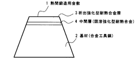
- the hot working tool further includes an intermediate layer made of a solid solution strengthened heat resistant alloy between the base material made of alloy tool steel and the precipitation strengthened heat resistant alloy layer.
- the method for producing a hot working tool of the present invention is a method for producing a hot working tool having a precipitation strengthening heat resistant alloy layer on a part or the whole of a work surface, wherein the precipitation strengthening heat resistant alloy layer comprises: In mass%, B: 0 to 0.02%, C: 0.01 to 0.15%, Mg: 0 to 0.01%, Al: 0.5 to 2.0%, Si: 0 to 1.
- the hot working tool is a hot forging die configured as an assembly of a plurality of hot die pieces, and the precipitation strengthening type heat resistance
- the alloy layer is preferably formed so as to cover at least part of the boundary between the hot mold pieces of the assembly.
- an intermediate layer made of a solid solution strengthening heat resistant alloy may be formed between the base material made of alloy tool steel and the precipitation strengthening heat resistant alloy layer. preferable.
- hot working tool By overlaying and using the metal powder of the present invention on the work surface of a hot working tool, it is excellent in high temperature strength in the initial stage of use, and further improved in strength by precipitation of hot intermetallic compounds during use.
- a hot working tool can be provided.
- hot working tools such as an anvil for hot forging are given further high temperature strength, wear resistance, high temperature sag resistance, and heat crack resistance, improving the use efficiency of hot working tools and Contributes to longer life.
- the hot working tool and the manufacturing method thereof of the present invention the high temperature strength is increased from the beginning of use, and it is possible to provide a hot working tool having a longer life than the conventional hot working tool. Therefore, it has a great effect on improving the processing accuracy in hot processing and reducing the number of maintenance steps.
- the important feature of the metal powder according to the present invention is that, when the work surface of the hot working tool is built up, the initial high temperature strength is high, and the precipitation of the intermetallic compound during the forging operation. Thus, the strength is further improved, and it is possible to contribute to the extension of the life of a tool for hot working such as an anvil for hot forging.
- An important feature of the hot working tool according to the present invention is that an optimum precipitation strengthening type heat resistant alloy layer is formed on the work surface of the hot working tool.
- Such metal powder is preferably used.
- the hardness of the conventional alloy equivalent to Udimet (R) 520 is about 370 HV.
- the hardness of the conventional alloy equivalent to Udimet (R) 520 is about 370 HV.
- the precipitation-strengthened heat-resistant alloy layer formed by overlaying and the metal powder for overlaying used for the formation need to have an alloy composition that provides a hardness of about 400 HV.
- the composition of the metal powder and precipitation strengthened heat resistant alloy layer of the present invention will be described in detail.
- the chemical composition is expressed as mass% unless otherwise specified.
- W and Mo are elements to be added in order to strengthen the austenite phase of the matrix (matrix) and increase the initial strength.
- W 3.0-7.0% W is an element effective as a solid solution element for increasing the high-temperature strength from the beginning and further improving the tensile strength, similar to Mo described later. Therefore, W needs to be at least 3.0%. However, the addition of W exceeding 7.0% adversely affects the stability of the structure like Mo, so the upper limit of W is set to 7.0%. The lower limit of W is more preferably 3.5%, still more preferably 4.0%. A more preferable upper limit of W is 5%.
- Mo: 3.0-7.0% Mo is an element effective for dissolving in the austenite phase, strengthening the matrix, and improving the high-temperature strength from the beginning. Therefore, Mo needs to be at least 3.0%. However, the addition of Mo exceeding 7.0% makes the structure unstable in the same manner as Cr described later, so the upper limit of Mo is 7.0%. A more preferable lower limit of Mo is 4.0%, and a more preferable upper limit of Mo is 5.0%.
- Ta, Al, and Ti are essential and added, and Nb can replace a part of Ta.
- These elements are elements that precipitate the ⁇ ′ phase.
- the aging process is performed to precipitate the ⁇ ′ phase, but in the present invention, the same effect as the aging process is obtained by utilizing the temperature during hot working.
- Ta exceeds 7.0%, precipitation of ⁇ phase (Ni 3 Ta) occurs and ductility deteriorates, so the upper limit of Ta is set to 7.0%.
- a more preferable lower limit of Ta is 3.0%, and a more preferable upper limit of Ta is 5.0%.
- Ta is an element that strengthens by dissolving in the austenite phase of the base in the same manner as W and Mo described above. It also enhances the effect.
- Nb 3% or less
- Ta + 2Nb 1.0 to 7.0%
- Nb is an element in the same group as Ta, and a part of Ta can be substituted with 3.0% or less of Nb.
- Nb improves high temperature strength and exerts the same effect as Ta described above.
- the addition of Nb has the effect of improving heat crack resistance when used as a hot working tool. Therefore, in order to improve heat crack resistance by adding Nb, it is preferable to add 1.0% or more of Nb. Since the effect of improving the high-temperature strength of Nb does not reach Ta, when Nb is added, it is added together with Ta. Even when Nb and Ta are added in combination, the total amount is 1.0 to 7.0% as in the case of adding Ta alone.
- Al 0.5 to 2.0% Al is an indispensable element for bonding with Ni to precipitate a stable ⁇ ′ phase and giving high temperature strength during hot working, and requires at least 0.5%.
- the ⁇ Ti + Ta (+ Nb) ⁇ / Al ratio in the ⁇ 'phase is increased to increase the lattice constant of the ⁇ ' phase, and the lattice strain due to precipitation of ⁇ 'is increased.
- the upper limit of Al is set to 2.0%.
- a more preferable lower limit of Al is 1.0%, and a more preferable upper limit of Al is 1.6%.
- Ti 1.0 to 3.0% Ti, like Al, binds to Ni and precipitates a ⁇ 'phase to increase the high temperature strength, and requires at least 1%.
- a large amount of Ti exceeding 3.0% decreases the solid solubility of Ta, which is an important element for the present invention, in the ⁇ ′ phase, and the ⁇ phase (Ni 3 Ti) precipitates to increase the strength. Reduce. Further, excessive addition of Ti may hinder weldability. Therefore, the upper limit of Ti is set to 3.0%.
- a more preferable lower limit of Ti is 2.1%, and a more preferable upper limit of Ti is 2.7%.
- B 0.02% or less B is effective in increasing the high-temperature strength and ductility by the grain boundary strengthening action, and can be added as necessary.
- B 0.02% or less B is effective in increasing the high-temperature strength and ductility by the grain boundary strengthening action, and can be added as necessary.
- B 0.02% or less B is effective in increasing the high-temperature strength and ductility by the grain boundary strengthening action, and can be added as necessary.
- B 0.02% or less B is effective in increasing the high-temperature strength and ductility by the grain boundary strengthening action, and can be added as necessary.
- B 0.02% or less B is effective in increasing the high-temperature strength and ductility by the grain boundary strengthening action, and can be added as necessary.
- B 0.02% or less B is effective in increasing the high-temperature strength and ductility by the grain boundary strengthening action, and can be added as necessary.
- B 0.02% or less B is effective in increasing the high-temperature strength and ductility by the grain boundary strengthening action, and can be added
- C needs to be at least 0.01%.
- an excessive amount of C exceeding 0.15% increases the amount of primary carbide produced and decreases the toughness, so the upper limit of C is set to 0.15%.
- O: 0.050% or less O is a harmful element that oxidizes the metal powder for overlaying during overlay welding.
- the upper limit of the metal powder is 0.050% or less.
- the lower limit of O is not particularly limited, but is practically 0.005%.
- Mg 0.01% or less Mg is an element that improves grain boundary ductility at high temperatures by deoxidation and desulfurization, and can be added as necessary. However, the above effect cannot be improved even if Mg is added in excess of 0.01%, so the upper limit when adding Mg is 0.01%.
- Si 0 to 1.0% Si is added as a deoxidizing element. When Si exceeds 1.0%, precipitation of harmful phases and high-temperature strength decrease. Therefore, the upper limit of Si is set to 1.0%. A preferable upper limit of Si is 0.5%. In order to obtain the above-described deoxidation effect more reliably, the lower limit of Si is preferably set to 0.05%. Mn: 0 to 1.0% Mn is also added as a deoxidizing element in the same manner as Si. When Mn exceeds 1.0%, precipitation of harmful phases and high-temperature strength are reduced. Therefore, the upper limit of Mn is 1%. A preferable upper limit of Mn is 0.5%.
- the lower limit of Mn is preferably set to 0.05%. Since Si and Mn are both deoxidizing elements as described above, the addition of the other element is not necessarily required if one of Si and Mn can be sufficiently deoxidized. For this reason, the lower limit of Si and Mn is set to 0% (no addition).
- Cr 15.0-22.0% Cr dissolves as a substitutional element in the base of the alloy and increases tensile strength, elastic limit and hardness. Further, since Cr has an effect of improving wear resistance, Cr needs to be at least 15.0%. However, the addition of Cr exceeding 22.0% not only destabilizes the structure, but also easily forms a ⁇ phase that is an embrittlement phase together with Mo and W, so the upper limit of Cr is set to 22.0%. To do. A more preferable lower limit of Cr is 17.0%, and a more preferable upper limit of Cr is 19.0%.
- Co 2.0-15.0% Co has an effect of increasing the solid solution amount of ⁇ 'in a high temperature region and an effect of improving weldability, and therefore requires at least 2.0%.
- the upper limit of Co is set to 15.0% in order to easily cause precipitation of harmful phases such as Laves phase.
- a more preferable lower limit of Co is 8.0%, and a more preferable upper limit of Co is 12.0%.
- the remaining Ni is a basic element constituting an austenite base and a ⁇ ′ precipitation strengthening phase of Ni 3 (Al, Ti, Ta) or Ni 3 (Al, Ti, Ta, Nb).
- contamination of Fe, P, S, Ca, Zr, etc. is usually considered as an impurity.
- the content is as follows, there is no particular problem in characteristics, so it is included in the alloy of the present invention. May be. Fe ⁇ 3.0%, P ⁇ 0.03%, S ⁇ 0.03%, Ca ⁇ 0.02%, Zr ⁇ 0.01%
- the present invention optimizes Mo and W which contribute to strength, and further contains element M (where M is Al). , Ti and Ta, and when Nb is contained, it represents four elements obtained by adding Nb to these elements.) All are considered to form a ⁇ ′ phase represented by Ni 3 M. It is preferable to adjust the composition so that the total of the ⁇ ′ phase forming elements obtained in this way is 20 to 45% in terms of calculation. Thereby, for example, the ⁇ ′ phase is precipitated at a temperature during hot working such as hot forging, and an aging effect is exhibited.
- the atomic percent of the ⁇ ′ phase is in the range of 20 to 45%.
- the above ⁇ ′ phase is based on calculations assuming that all of Al, Ti, Ta, and Nb are ⁇ ′ phases (Ni 3 M). In the calculation, first, the components of the metal powder or the precipitation strengthening heat resistant alloy layer are expressed in atomic%, and the ratio of the elements forming Ni 3 M is calculated from the sum of Al, Ti, Ta, and Nb. .
- the particle size is preferably 50 to 300 ⁇ m.
- the particle size of the metal powder is preferably 50 to 300 ⁇ m.
- the average particle size is preferably in the range of 150 to 200 ⁇ m. If the average particle size is excessively small, it tends to evaporate as a fume during overlaying.
- the metal powder of the present invention is excellent in initial high-temperature strength, and can be further improved in strength by precipitation of intermetallic compounds during hot use. Suitable for serving powder.
- Other applications include, for example, raw material powder for 3D printers. By using the raw material for the 3D printer, it is possible to form a hot working tool having a complicated shape with a high yield.
- the O content in gas components such as arc gas, shield gas and carrier gas used in the build-up welding machine is 0. 0001 vol% or less is preferable.
- the metal powder for building-up of the present invention may be oxidized in an atmosphere containing a large amount of O.
- the gas used may be an inert gas or a mixed gas containing these as main components.
- Ar gas it is preferable to use Ar gas as the gas to be used because the gas containing N 2 may be nitrided by the built-up layer.
- the hot working tool according to the present invention has a precipitation-strengthened heat-resistant alloy layer having the above-described composition or the like on a part of or the entire work surface.
- a method for forming the precipitation-strengthening heat-resistant alloy layer on the work surface an appropriate method may be adopted depending on the type of the tool. For example, in the case of a hot rolling roll, centrifugal casting or overlay welding may be applied. Moreover, if it is a hot forging die or anvil, a known technique such as overlay welding can be employed.
- Overlay welding can be applied to complex shapes, and is particularly preferable as a method for forming a precipitation-strengthened heat-resistant alloy layer.
- the overlaying method include a method of processing the alloy into a wire and overlaying, and a method of using metal powder having the alloy composition, and any method may be used.
- Overlaying with metal powder can also suppress segregation of components and does not require processing up to the wire, which is advantageous from the viewpoint of the characteristics of the overlaid alloy and the manufacturing cost.
- whether to form the precipitation-strengthening heat-resistant alloy layer of the present invention in part or over the entire surface is suitably determined according to the type of hot working tool. For example, in the case of an anvil for hot forging, it is preferable to form a precipitation strengthening heat resistant alloy layer on the entire surface. Further, in the case of a hot forging die, a portion to which stress is applied may be selected to form a precipitation strengthening heat resistant alloy layer, or of course, a precipitation strengthening heat resistant alloy layer may be formed on the entire surface. .
- the precipitation-strengthening type heat-resistant alloy layer it is economically advantageous to build up the alloy specified in the present invention on the work surface using an inexpensive alloy tool steel as a base material.
- an alloy tool steel is used as a base material and an alloy having a composition defined in the present invention is built up on the work surface, the base material and the striking surface are made of different alloys, so that the different characteristics of each different alloy have. Can be granted.
- the work surface provides high hardness necessary for striking and pressing the work material, while realizing high rigidity for the base material, making it possible to relieve stress of hot working tools. To do.
- the alloy tool steel used as a base material may be any one described in JIS-G4404.
- a typical component range shows C: 0.25 to 0.5%, Si: 1.2% or less, and Mn: 1.0 by mass%.
- the alloy tool steel as the base material is used after being quenched to 800 to 1100 ° C. and tempered to 500 to 700 ° C., and adjusted to a hardness of about 330 to 380 HBW.
- a precipitation strengthened heat resistant material composed of a base material made of alloy tool steel and an alloy specified in the present invention.
- An intermediate layer made of a solid solution strengthened heat-resistant alloy can be further provided between the alloy layers.
- the solid solution strengthened heat resistant alloy used in the intermediate layer does not use the strengthening mechanism of the solid solution strengthened heat resistant alloy, and improves the weldability as described above or relaxes the stress. It is used as a layer.
- the intermediate layer may be a single layer or may be formed by stacking two or more solid solution strengthened heat resistant alloys having different components.
- the solid solution strengthened heat-resistant alloy referred to in the present invention is, for example, an alloy having a composition shown in JIS-G4901 or G4902, which can strengthen the matrix (matrix) by dissolving an alloy element.
- An alloy having a composition or an alloy described in ASTM-A494 may be used.
- Typical component ranges are represented by mass%, C: 0.15% or less, Cr: 15.0 to 30.0%, Co: 0 to 3.0%, Mo: 0 to 30.0%, W: 0 to 10.0%, Nb: 0 to 4.0%, Ta: 0 to 4.0%, Ti: 0 to 1.0%, Al: 0 to 2.0%, Fe: 0 to 20 0.0%, Mn: 0 to 4.0%, with the balance being Ni and impurities.
- the hardness of the striking surface is 330 HV or higher even in a hot working tool in which an intermediate layer is formed. When the hardness of the striking surface is 330 HV or higher, the strength of the striking surface at the forging temperature can be sufficiently ensured. Preferably it is 350HV or more.
- FIG. 1 shows an example of an anvil for hot forging.
- An anvil 1 for hot forging has a precipitation strengthening heat resistant alloy layer 3 on the striking surface (working surface) of the upper surface of a base material 2 made of alloy tool steel.
- an intermediate layer 4 made of a solid solution strengthened heat resistant alloy is disposed between the precipitation strengthened heat resistant alloy layer 3 and the substrate 2.
- FIG. 2 shows an example of a hot forging die.
- the hot forging die can be constituted by a single substrate, but in the example shown in FIG.
- a cylindrical hot mold piece 6 (hereinafter referred to as a cylindrical hot mold piece) is the center when assembled, and an outer peripheral ring-shaped hot mold piece 7 (hereinafter referred to as an outer peripheral ring shape) around the center.
- the hot forging die 5 is obtained by concentrically fitting the hot die pieces).
- the precipitation strengthening type heat resistant alloy layer 3 is disposed on the working surface of a hot forging die 5 which is an assembly of a plurality of hot die pieces. This configuration is used, for example, when manufacturing a disk-shaped hot forging material. Also, for example, as shown in FIG.
- the ring-shaped hot mold piece 8 is the center when assembled, and the outer peripheral ring-shaped hot mold piece 7 is concentrically fitted around it
- An integrated hot forging die 5 can also be configured. This configuration is used, for example, when manufacturing a ring-shaped hot forging material.
- the diameter of the hot forging die can be increased by concentrically fitting several outer peripheral ring-shaped hot die pieces according to the size of the workpiece. .
- the mold pieces can be constrained during forging, they are comparable in strength to an integral mold.
- by fitting a plurality of mold pieces it is possible to reduce the man-hours required for metal mold production compared to conventional one-piece mold production by machining from a very large material block. , Productivity can also be improved.
- the precipitation-strengthening heat resistant alloy layer 3 is disposed so as to cover at least a part of the boundary between the hot mold pieces of the assembly.
- the hot forging die of the present invention is used for the upper die, the diameter on the surface side in contact with the material to be forged is increased in order to surely prevent each hot die piece from falling. It is good to leave.
- methods such as shrink fitting and cold fitting can be used in addition to simple fitting.
- the prepared cylindrical hot mold piece raw material is cut by cutting. It is easy to process.
- ring-shaped hot mold piece materials and outer peripheral parts by hollow forging (core metal forging) using core metal or ring mill rolling It is easy to manufacture a ring-shaped hot mold piece material and process the material into a desired dimension by cutting.
- 2 and 3 show an application example of a ring shape or a disk shape. For example, hot forging dies for a long shaft such as a shaft, etc. It is also good.
- Example 1 The present invention is described in more detail below. The effect when the metal powder of the present invention was used for overlaying was confirmed.
- the metal powder of the present invention and an alloy equivalent to Udimet 520 disclosed in Patent Documents 1 and 2 were produced by gas atomization.
- the gas used was Ar gas (4N) for the purpose of preventing an increase in oxygen content.
- the particle diameter of the metal powder for building-up was classified into 65 to 250 ⁇ m, and the average particle diameter was measured to be 180 ⁇ m. Table 1 shows the chemical composition of the obtained metal powder for building-up.
- the alloy composition of the present invention was converted into an atomic ratio and applied to Ni 3 M (M is Al, Ti, Ta) and the total of the elements forming the ⁇ ′ phase was calculated, it was 27.2%. .
- the calculation of the ⁇ ′ phase by Ni 3 M was performed as Ni 3 (Al 0.36 Ti 0.45 Ta 0.19 ).
- the metal powder of the present invention not only the initial high-temperature strength of the tool for hot working is increased, but also the temperature of the heated material to be forged and the temperature due to heat generation during hot forging. Utilizing it, it was confirmed that the effect of an aging treatment for precipitating the ⁇ ′ phase while hot forging was also obtained.
- a test piece of ⁇ 6 mm ⁇ 10 mm is formed from the overlaying layer.
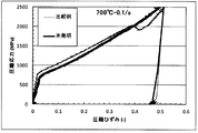
- Samples were collected and examined for hot strength in a greeble test. The test was conducted at 700 ° C. and 900 ° C. with a strain rate of 0.1 s ⁇ 1 .
- the test temperature holding time of the greeble test piece was 10 minutes, and the superiority of the initial high temperature strength was evaluated.
- the test results are shown in FIG. 4 (700 ° C.) and FIG. 5 (900 ° C.). As shown in FIG.
- the precipitation-strengthened heat-resistant alloy cut out from the overlay layer of the present invention can obtain high strength exceeding 2500 MPa even at 50% compression. It can be seen that shear failure occurs at approximately 40% compression.
- the precipitation-strengthened heat-resistant alloy cut out from the built-up layer of the present invention can maintain a high strength of about 1800 MPa even at 50% compression. It can be seen that the strength is about 1400 MPa at approximately 30% compression, and then becomes saturated. From the above results, it can be seen that the metal powder of the present invention is excellent in the initial high-temperature strength.
- the structure which concerns on this invention was applied with respect to the anvil for hot forging which has a big load to the tool for hot processing among the tools for hot processing.
- the metal powder according to the present invention was used for overlaying to form a precipitation strengthened heat resistant alloy layer on the work surface.
- the manufacturing method of the anvil for hot forging used by the example of this invention is demonstrated.
- a base material 2 made of JIS-SKT4 adjusted to Brinell hardness of 352 HBW by quenching at 870 ° C. ⁇ 1 hour and tempering at 640 ° C. ⁇ 4 hours was added to the base layer 2 made of JIS-SKT4 by 0.04% C by mass as the intermediate layer 4.
- the alloy layer consisting of Fe and the balance Ni and the build-up is welded, and the precipitation strengthening heat resistant alloy layer 3 has the composition shown in Table 1.
- An anvil for hot forging having a structure shown in FIG. 1 was produced by overlaying 20 mm by PTA (Plasma-Transferred-Arc) welding using the metal powder for overlaying.
- the overlaying as a comparative example was performed.
- the alloy used for overlaying is an alloy equivalent to Udimet (R) 520 described in Patent Document 1, which is advantageous in high-temperature strength as compared with Alloy 718 alloy and the like.
- Table 3 shows the composition of the precipitation strengthening heat resistant alloy layer (working surface) and the composition of the intermediate layer of the comparative example.
- the precipitation-strengthened heat-resistant alloy layer which is a build-up layer, was formed on the entire work surface.
- hot forging was performed from 8-mm 130 mm to ⁇ 90 mm with a load of 700 to 750 tons by four-side forging using the above-described hot forging anvils of the present invention and comparative examples.
- the to-be-forged materials were long products made of difficult-to-process Udimet® 520 equivalent alloy, and all had the same shape and weight.
- the temperature of the striking surface during forging is about 850 ° C.
- the total working time of hot forging using the anvil for hot forging of the present invention is about 5 hours.
- the effect of the aging treatment for precipitating the ⁇ 'phase could be sufficiently exhibited.
- the number of forgings in the hot forging anvil of the example of the present invention was 36, whereas the number of forgings was 18 in the anvil for hot forging of the comparative example.
- the anvil for forging could be forged twice as many as the comparative example. From this, in the anvil for hot forging of the example of the present invention, it is excellent in the initial high temperature strength as compared with the comparative example, and since the ⁇ ′ phase precipitation effect is obtained as in the aging treatment during the hot forging, It was confirmed that a long life was achieved.
- the hot working tool built up with the metal powder for overlaying of the present invention can maintain high strength especially at high temperature, so that not only the life of the hot working tool can be extended, but also the destruction Since defects such as cracks and cracks can also be suppressed, it has a great effect on improving the machining accuracy in hot working and reducing the number of maintenance steps.
- Example 2 Next, the element which affects the heat crack resistance which becomes a problem when actually used as a tool for hot working was investigated.
- the studied compositions are shown in Table 4.
- the particle size was classified into 65 to 250 ⁇ m and the average particle size was measured and found to be 180 ⁇ m.
- this metal powder of the present invention for overlaying, it was built up by the PTA method to form a built-up layer.
- a test piece of ⁇ 4 mm ⁇ 20 mm was taken from the build-up layer, and the thermal expansion coefficient was measured with a thermal expansion measuring device. Further, the calculation of the ⁇ ′ phase by Ni 3 M was performed at the ratio shown in Table 5.
- the thermal expansion measurement was performed using a RGAKU TMA8310 type thermal expansion measuring device at a temperature rising rate of 10 ° C./min and a temperature rising from room temperature to 1000 ° C. in an Ar atmosphere.
- Table 6 and FIG. 6 show the test results in the range of 500 ° C. to 900 ° C., which is assumed to be the operating temperature range in hot working.
- Nb content and the Ta + Nb content within the ranges defined in the present invention both have excellent low thermal expansion characteristics. Moreover, it turns out that a thermal expansion coefficient falls by increasing Ta + Nb amount. This is presumably because Nb having a high binding energy in the metal bond was dissolved in the base material to suppress thermal expansion. From the above results, it was found that the addition of Nb, which is a precipitation strengthening element, exhibits excellent heat crack resistance while having high strength. For this reason, positive addition of Nb is effective in increasing the high-temperature strength and heat crack resistance.
Landscapes
- Engineering & Computer Science (AREA)
- Mechanical Engineering (AREA)
- Chemical & Material Sciences (AREA)
- Materials Engineering (AREA)
- Metallurgy (AREA)
- Organic Chemistry (AREA)
- Physics & Mathematics (AREA)
- Optics & Photonics (AREA)
- Plasma & Fusion (AREA)
- Powder Metallurgy (AREA)
- Forging (AREA)
Abstract
L'invention porte sur une poudre métallique qui permet, lorsqu'elle est transformée en une surface de travail d'un outil pour corroyage, par exemple une enclume, un moule pour forgeage à chaud tel qu'un moule métallique ou un rouleau pour laminage à chaud, de prolonger la durée de vie de l'outil pour corroyage. La poudre métallique comprend, en termes de % en masse : pas plus de 0,02 % de B ; pas plus de 0,050 % d'O ; 0,01-0,15 % de C ; pas plus de 0,01 % de Mg ; 0,5-2 % d'Al ; 0-1 % de Si ; 0-1 % de Mn ; 1-3 % de Ti ; 15-22 % de Cr ; 2-15 % de Co ; pas plus de 3 % de Nb ; 3-7 % de Mo ; 1-7 % de Ta ; 3-7 % de W ; et 1-7 % au total de Ta, soit seul soit sous forme de Ta + 2Nb ; le reste étant constitué de Ni et d'impuretés.
Priority Applications (1)
| Application Number | Priority Date | Filing Date | Title |
|---|---|---|---|
| JP2014525655A JP5601607B1 (ja) | 2013-02-13 | 2014-02-12 | 金属粉末、熱間加工用工具および熱間加工用工具の製造方法 |
Applications Claiming Priority (4)
| Application Number | Priority Date | Filing Date | Title |
|---|---|---|---|
| JP2013-025441 | 2013-02-13 | ||
| JP2013025441 | 2013-02-13 | ||
| JP2013-031393 | 2013-02-20 | ||
| JP2013031393 | 2013-02-20 |
Publications (1)
| Publication Number | Publication Date |
|---|---|
| WO2014126086A1 true WO2014126086A1 (fr) | 2014-08-21 |
Family
ID=51354086
Family Applications (1)
| Application Number | Title | Priority Date | Filing Date |
|---|---|---|---|
| PCT/JP2014/053151 Ceased WO2014126086A1 (fr) | 2013-02-13 | 2014-02-12 | Poudre métallique, outil pour corroyage et procédé pour la fabrication d'outil pour corroyage |
Country Status (2)
| Country | Link |
|---|---|
| JP (1) | JP5601607B1 (fr) |
| WO (1) | WO2014126086A1 (fr) |
Cited By (13)
| Publication number | Priority date | Publication date | Assignee | Title |
|---|---|---|---|---|
| WO2016052423A1 (fr) * | 2014-09-29 | 2016-04-07 | 日立金属株式会社 | SURCHAUFFE Ni À BASE D'UN ALLIAGE RÉFRACTAIRE. |
| JP2017082324A (ja) * | 2015-10-05 | 2017-05-18 | ゼネラル エレクトリック テクノロジー ゲゼルシャフト ミット ベシュレンクテル ハフツングGeneral Electric Technology GmbH | 選択的レーザ融解用の金属粉末の処理方法 |
| EP3719152A4 (fr) * | 2017-11-29 | 2021-03-31 | Hitachi Metals, Ltd. | ALLIAGE À BASE DE Ni POUR MATRICE DE FORMAGE À CHAUD, ET MATRICE DE FORGEAGE À CHAUD L'UTILISANT |
| EP3719153A4 (fr) * | 2017-11-29 | 2021-04-07 | Hitachi Metals, Ltd. | Alliage à base de ni pour filière chaude, filière de forgeage à chaud l'utilisant, et procédé de fabrication de produits forgés |
| JP2021194653A (ja) * | 2020-06-10 | 2021-12-27 | 日立金属株式会社 | 熱間加工用工具 |
| US11458537B2 (en) | 2017-03-29 | 2022-10-04 | Mitsubishi Heavy Industries, Ltd. | Heat treatment method for additive manufactured Ni-base alloy object, method for manufacturing additive manufactured Ni-base alloy object, Ni-base alloy powder for additive manufactured object, and additive manufactured Ni-base alloy object |
| CN115558843A (zh) * | 2021-09-08 | 2023-01-03 | 僖昴晰(上海)新材料有限公司 | 一种合金钢组合物 |
| US11634792B2 (en) | 2017-07-28 | 2023-04-25 | Alloyed Limited | Nickel-based alloy |
| CN116904802A (zh) * | 2023-07-17 | 2023-10-20 | 东北大学 | 一种低裂纹敏感性的增材适用镍基高温合金及制备方法 |
| US12241144B2 (en) | 2019-06-07 | 2025-03-04 | Alloyed Limited | Nickel-based alloy |
| CN119753500A (zh) * | 2024-12-26 | 2025-04-04 | 益阳橡胶塑料机械集团有限公司 | 堆焊用合金材料、堆焊方法及机械零件 |
| US12319985B2 (en) | 2019-10-02 | 2025-06-03 | Alloyed Limited | Nickel-based alloy |
| EP4367279A4 (fr) * | 2021-07-09 | 2026-01-28 | Ati Properties Llc | Alliages à base de nickel |
Citations (4)
| Publication number | Priority date | Publication date | Assignee | Title |
|---|---|---|---|---|
| JPH083669A (ja) * | 1994-06-20 | 1996-01-09 | Mitsubishi Materials Corp | 溶射用Ni基合金粉末およびNi基合金粉末を溶射して得られる複合部材 |
| JP2006070360A (ja) * | 2004-09-03 | 2006-03-16 | Haynes Internatl Inc | 進歩したガスタービンエンジン用Ni−Cr−Co合金 |
| JP2006291344A (ja) * | 2005-04-15 | 2006-10-26 | Hitachi Ltd | Ni基合金部材とその製造法及びタービンエンジン部品並びに溶接材料とその製造法 |
| JP2007136509A (ja) * | 2005-11-18 | 2007-06-07 | Sanyo Special Steel Co Ltd | 連続鋳造ロール肉盛用溶接材料およびロール |
-
2014
- 2014-02-12 JP JP2014525655A patent/JP5601607B1/ja active Active
- 2014-02-12 WO PCT/JP2014/053151 patent/WO2014126086A1/fr not_active Ceased
Patent Citations (4)
| Publication number | Priority date | Publication date | Assignee | Title |
|---|---|---|---|---|
| JPH083669A (ja) * | 1994-06-20 | 1996-01-09 | Mitsubishi Materials Corp | 溶射用Ni基合金粉末およびNi基合金粉末を溶射して得られる複合部材 |
| JP2006070360A (ja) * | 2004-09-03 | 2006-03-16 | Haynes Internatl Inc | 進歩したガスタービンエンジン用Ni−Cr−Co合金 |
| JP2006291344A (ja) * | 2005-04-15 | 2006-10-26 | Hitachi Ltd | Ni基合金部材とその製造法及びタービンエンジン部品並びに溶接材料とその製造法 |
| JP2007136509A (ja) * | 2005-11-18 | 2007-06-07 | Sanyo Special Steel Co Ltd | 連続鋳造ロール肉盛用溶接材料およびロール |
Cited By (23)
| Publication number | Priority date | Publication date | Assignee | Title |
|---|---|---|---|---|
| WO2016052423A1 (fr) * | 2014-09-29 | 2016-04-07 | 日立金属株式会社 | SURCHAUFFE Ni À BASE D'UN ALLIAGE RÉFRACTAIRE. |
| JP5995158B2 (ja) * | 2014-09-29 | 2016-09-21 | 日立金属株式会社 | Ni基超耐熱合金 |
| CN106661674A (zh) * | 2014-09-29 | 2017-05-10 | 日立金属株式会社 | Ni基超耐热合金 |
| US9828657B2 (en) | 2014-09-29 | 2017-11-28 | Hitachi Metals, Ltd. | Ni-base super alloy |
| JP2017082324A (ja) * | 2015-10-05 | 2017-05-18 | ゼネラル エレクトリック テクノロジー ゲゼルシャフト ミット ベシュレンクテル ハフツングGeneral Electric Technology GmbH | 選択的レーザ融解用の金属粉末の処理方法 |
| US11458537B2 (en) | 2017-03-29 | 2022-10-04 | Mitsubishi Heavy Industries, Ltd. | Heat treatment method for additive manufactured Ni-base alloy object, method for manufacturing additive manufactured Ni-base alloy object, Ni-base alloy powder for additive manufactured object, and additive manufactured Ni-base alloy object |
| US12258655B2 (en) | 2017-07-28 | 2025-03-25 | Alloyed Limited | Nickel-based alloy |
| US11634792B2 (en) | 2017-07-28 | 2023-04-25 | Alloyed Limited | Nickel-based alloy |
| EP3719153A4 (fr) * | 2017-11-29 | 2021-04-07 | Hitachi Metals, Ltd. | Alliage à base de ni pour filière chaude, filière de forgeage à chaud l'utilisant, et procédé de fabrication de produits forgés |
| US11326231B2 (en) | 2017-11-29 | 2022-05-10 | Hitachi Metals, Ltd. | Ni-based alloy for hot-working die, and hot-forging die using same |
| EP3719152A4 (fr) * | 2017-11-29 | 2021-03-31 | Hitachi Metals, Ltd. | ALLIAGE À BASE DE Ni POUR MATRICE DE FORMAGE À CHAUD, ET MATRICE DE FORGEAGE À CHAUD L'UTILISANT |
| US11692246B2 (en) | 2017-11-29 | 2023-07-04 | Proterial, Ltd. | Ni-based alloy for hot-working die, and hot-forging die using same |
| US12241144B2 (en) | 2019-06-07 | 2025-03-04 | Alloyed Limited | Nickel-based alloy |
| US12319985B2 (en) | 2019-10-02 | 2025-06-03 | Alloyed Limited | Nickel-based alloy |
| JP2024133491A (ja) * | 2020-06-10 | 2024-10-02 | 株式会社プロテリアル | 熱間加工用工具の製造方法 |
| JP7508873B2 (ja) | 2020-06-10 | 2024-07-02 | 株式会社プロテリアル | 熱間加工用工具 |
| JP2021194653A (ja) * | 2020-06-10 | 2021-12-27 | 日立金属株式会社 | 熱間加工用工具 |
| JP7708271B2 (ja) | 2020-06-10 | 2025-07-15 | 株式会社プロテリアル | 熱間加工用工具の製造方法 |
| EP4367279A4 (fr) * | 2021-07-09 | 2026-01-28 | Ati Properties Llc | Alliages à base de nickel |
| CN115558843A (zh) * | 2021-09-08 | 2023-01-03 | 僖昴晰(上海)新材料有限公司 | 一种合金钢组合物 |
| CN116904802A (zh) * | 2023-07-17 | 2023-10-20 | 东北大学 | 一种低裂纹敏感性的增材适用镍基高温合金及制备方法 |
| CN116904802B (zh) * | 2023-07-17 | 2025-08-12 | 东北大学 | 一种低裂纹敏感性的增材适用镍基高温合金及制备方法 |
| CN119753500A (zh) * | 2024-12-26 | 2025-04-04 | 益阳橡胶塑料机械集团有限公司 | 堆焊用合金材料、堆焊方法及机械零件 |
Also Published As
| Publication number | Publication date |
|---|---|
| JP5601607B1 (ja) | 2014-10-08 |
| JPWO2014126086A1 (ja) | 2017-02-02 |
Similar Documents
| Publication | Publication Date | Title |
|---|---|---|
| JP5601607B1 (ja) | 金属粉末、熱間加工用工具および熱間加工用工具の製造方法 | |
| JP6052317B2 (ja) | 熱間鍛造用金型 | |
| JP6839401B1 (ja) | Ni基超耐熱合金及びNi基超耐熱合金の製造方法 | |
| JP5742447B2 (ja) | 高硬度肉盛合金粉末 | |
| EP2479302B1 (fr) | Alliage thermorésistant à base de Ni, composant de turbine à gaz et turbine à gaz | |
| JP5501617B2 (ja) | 鋼組成物、その形成方法、及びそれから形成した物品 | |
| JP6719216B2 (ja) | α−β型チタン合金 | |
| JP2013177668A (ja) | Ni基合金、その製造方法およびタービン用部品 | |
| JPH0885838A (ja) | Ni基超耐熱合金 | |
| JP2010280950A (ja) | 排気バルブ用耐熱鋼及びその製造方法 | |
| JP2013052441A (ja) | 熱間鍛造用金敷および熱間鍛造方法 | |
| JP5437669B2 (ja) | 温熱間鍛造用金型 | |
| WO2013027841A1 (fr) | Acier résistant à la chaleur pour soupapes d'échappement | |
| WO2014014069A1 (fr) | Procédé de fabrication d'une soupape d'échappement de moteur pour gros navire | |
| WO2017170433A1 (fr) | Procédé destiné à la production d'alliage à base de ni à très haute résistance à la chaleur | |
| JP2007254804A (ja) | Ni基合金 | |
| JP7708271B2 (ja) | 熱間加工用工具の製造方法 | |
| JP2013108112A (ja) | 合金鋼製エンドミル | |
| JP5720302B2 (ja) | 歯切工具 | |
| JP5510665B2 (ja) | 優れた高温焼戻し軟化抵抗性を有する合金鋼 | |
| JP2012210671A (ja) | 合金鋼製ドリル | |
| JP2017024051A (ja) | 肉盛溶接用材料及び肉盛金属 | |
| JP2013036079A (ja) | 合金鋼製エンドミル | |
| JP2011225958A (ja) | 合金鋼製エンドミル | |
| JP2011224759A (ja) | 合金鋼製ドリル |
Legal Events
| Date | Code | Title | Description |
|---|---|---|---|
| ENP | Entry into the national phase |
Ref document number: 2014525655 Country of ref document: JP Kind code of ref document: A |
|
| 121 | Ep: the epo has been informed by wipo that ep was designated in this application |
Ref document number: 14751447 Country of ref document: EP Kind code of ref document: A1 |
|
| NENP | Non-entry into the national phase |
Ref country code: DE |
|
| 122 | Ep: pct application non-entry in european phase |
Ref document number: 14751447 Country of ref document: EP Kind code of ref document: A1 |