WO2014128959A1 - 二酸化炭素液化装置 - Google Patents
二酸化炭素液化装置 Download PDFInfo
- Publication number
- WO2014128959A1 WO2014128959A1 PCT/JP2013/054736 JP2013054736W WO2014128959A1 WO 2014128959 A1 WO2014128959 A1 WO 2014128959A1 JP 2013054736 W JP2013054736 W JP 2013054736W WO 2014128959 A1 WO2014128959 A1 WO 2014128959A1
- Authority
- WO
- WIPO (PCT)
- Prior art keywords
- carbon dioxide
- unit
- gaseous
- heat source
- cold heat
- Prior art date
- Legal status (The legal status is an assumption and is not a legal conclusion. Google has not performed a legal analysis and makes no representation as to the accuracy of the status listed.)
- Ceased
Links
Images

Classifications
-
- F—MECHANICAL ENGINEERING; LIGHTING; HEATING; WEAPONS; BLASTING
- F25—REFRIGERATION OR COOLING; COMBINED HEATING AND REFRIGERATION SYSTEMS; HEAT PUMP SYSTEMS; MANUFACTURE OR STORAGE OF ICE; LIQUEFACTION SOLIDIFICATION OF GASES
- F25J—LIQUEFACTION, SOLIDIFICATION OR SEPARATION OF GASES OR GASEOUS OR LIQUEFIED GASEOUS MIXTURES BY PRESSURE AND COLD TREATMENT OR BY BRINGING THEM INTO THE SUPERCRITICAL STATE
- F25J1/00—Processes or apparatus for liquefying or solidifying gases or gaseous mixtures
- F25J1/0002—Processes or apparatus for liquefying or solidifying gases or gaseous mixtures characterised by the fluid to be liquefied
- F25J1/0027—Oxides of carbon, e.g. CO2
-
- C—CHEMISTRY; METALLURGY
- C01—INORGANIC CHEMISTRY
- C01B—NON-METALLIC ELEMENTS; COMPOUNDS THEREOF; METALLOIDS OR COMPOUNDS THEREOF NOT COVERED BY SUBCLASS C01C
- C01B32/00—Carbon; Compounds thereof
- C01B32/50—Carbon dioxide
-
- F—MECHANICAL ENGINEERING; LIGHTING; HEATING; WEAPONS; BLASTING
- F25—REFRIGERATION OR COOLING; COMBINED HEATING AND REFRIGERATION SYSTEMS; HEAT PUMP SYSTEMS; MANUFACTURE OR STORAGE OF ICE; LIQUEFACTION SOLIDIFICATION OF GASES
- F25J—LIQUEFACTION, SOLIDIFICATION OR SEPARATION OF GASES OR GASEOUS OR LIQUEFIED GASEOUS MIXTURES BY PRESSURE AND COLD TREATMENT OR BY BRINGING THEM INTO THE SUPERCRITICAL STATE
- F25J1/00—Processes or apparatus for liquefying or solidifying gases or gaseous mixtures
- F25J1/02—Processes or apparatus for liquefying or solidifying gases or gaseous mixtures requiring the use of refrigeration, e.g. of helium or hydrogen ; Details and kind of the refrigeration system used; Integration with other units or processes; Controlling aspects of the process
- F25J1/0221—Processes or apparatus for liquefying or solidifying gases or gaseous mixtures requiring the use of refrigeration, e.g. of helium or hydrogen ; Details and kind of the refrigeration system used; Integration with other units or processes; Controlling aspects of the process using the cold stored in an external cryogenic component in an open refrigeration loop
-
- F—MECHANICAL ENGINEERING; LIGHTING; HEATING; WEAPONS; BLASTING
- F25—REFRIGERATION OR COOLING; COMBINED HEATING AND REFRIGERATION SYSTEMS; HEAT PUMP SYSTEMS; MANUFACTURE OR STORAGE OF ICE; LIQUEFACTION SOLIDIFICATION OF GASES
- F25J—LIQUEFACTION, SOLIDIFICATION OR SEPARATION OF GASES OR GASEOUS OR LIQUEFIED GASEOUS MIXTURES BY PRESSURE AND COLD TREATMENT OR BY BRINGING THEM INTO THE SUPERCRITICAL STATE
- F25J1/00—Processes or apparatus for liquefying or solidifying gases or gaseous mixtures
- F25J1/02—Processes or apparatus for liquefying or solidifying gases or gaseous mixtures requiring the use of refrigeration, e.g. of helium or hydrogen ; Details and kind of the refrigeration system used; Integration with other units or processes; Controlling aspects of the process
- F25J1/0228—Coupling of the liquefaction unit to other units or processes, so-called integrated processes
- F25J1/0234—Integration with a cryogenic air separation unit
-
- F—MECHANICAL ENGINEERING; LIGHTING; HEATING; WEAPONS; BLASTING
- F25—REFRIGERATION OR COOLING; COMBINED HEATING AND REFRIGERATION SYSTEMS; HEAT PUMP SYSTEMS; MANUFACTURE OR STORAGE OF ICE; LIQUEFACTION SOLIDIFICATION OF GASES
- F25J—LIQUEFACTION, SOLIDIFICATION OR SEPARATION OF GASES OR GASEOUS OR LIQUEFIED GASEOUS MIXTURES BY PRESSURE AND COLD TREATMENT OR BY BRINGING THEM INTO THE SUPERCRITICAL STATE
- F25J3/00—Processes or apparatus for separating the constituents of gaseous or liquefied gaseous mixtures involving the use of liquefaction or solidification
- F25J3/02—Processes or apparatus for separating the constituents of gaseous or liquefied gaseous mixtures involving the use of liquefaction or solidification by rectification, i.e. by continuous interchange of heat and material between a vapour stream and a liquid stream
- F25J3/04—Processes or apparatus for separating the constituents of gaseous or liquefied gaseous mixtures involving the use of liquefaction or solidification by rectification, i.e. by continuous interchange of heat and material between a vapour stream and a liquid stream for air
- F25J3/04151—Purification and (pre-)cooling of the feed air; recuperative heat-exchange with product streams
- F25J3/04187—Cooling of the purified feed air by recuperative heat-exchange; Heat-exchange with product streams
- F25J3/04193—Division of the main heat exchange line in consecutive sections having different functions
- F25J3/042—Division of the main heat exchange line in consecutive sections having different functions having an intermediate feed connection
-
- F—MECHANICAL ENGINEERING; LIGHTING; HEATING; WEAPONS; BLASTING
- F25—REFRIGERATION OR COOLING; COMBINED HEATING AND REFRIGERATION SYSTEMS; HEAT PUMP SYSTEMS; MANUFACTURE OR STORAGE OF ICE; LIQUEFACTION SOLIDIFICATION OF GASES
- F25J—LIQUEFACTION, SOLIDIFICATION OR SEPARATION OF GASES OR GASEOUS OR LIQUEFIED GASEOUS MIXTURES BY PRESSURE AND COLD TREATMENT OR BY BRINGING THEM INTO THE SUPERCRITICAL STATE
- F25J3/00—Processes or apparatus for separating the constituents of gaseous or liquefied gaseous mixtures involving the use of liquefaction or solidification
- F25J3/02—Processes or apparatus for separating the constituents of gaseous or liquefied gaseous mixtures involving the use of liquefaction or solidification by rectification, i.e. by continuous interchange of heat and material between a vapour stream and a liquid stream
- F25J3/04—Processes or apparatus for separating the constituents of gaseous or liquefied gaseous mixtures involving the use of liquefaction or solidification by rectification, i.e. by continuous interchange of heat and material between a vapour stream and a liquid stream for air
- F25J3/04248—Generation of cold for compensating heat leaks or liquid production, e.g. by Joule-Thompson expansion
- F25J3/04284—Generation of cold for compensating heat leaks or liquid production, e.g. by Joule-Thompson expansion using internal refrigeration by open-loop gas work expansion, e.g. of intermediate or oxygen enriched (waste-)streams
- F25J3/04309—Generation of cold for compensating heat leaks or liquid production, e.g. by Joule-Thompson expansion using internal refrigeration by open-loop gas work expansion, e.g. of intermediate or oxygen enriched (waste-)streams of nitrogen
-
- F—MECHANICAL ENGINEERING; LIGHTING; HEATING; WEAPONS; BLASTING
- F25—REFRIGERATION OR COOLING; COMBINED HEATING AND REFRIGERATION SYSTEMS; HEAT PUMP SYSTEMS; MANUFACTURE OR STORAGE OF ICE; LIQUEFACTION SOLIDIFICATION OF GASES
- F25J—LIQUEFACTION, SOLIDIFICATION OR SEPARATION OF GASES OR GASEOUS OR LIQUEFIED GASEOUS MIXTURES BY PRESSURE AND COLD TREATMENT OR BY BRINGING THEM INTO THE SUPERCRITICAL STATE
- F25J3/00—Processes or apparatus for separating the constituents of gaseous or liquefied gaseous mixtures involving the use of liquefaction or solidification
- F25J3/02—Processes or apparatus for separating the constituents of gaseous or liquefied gaseous mixtures involving the use of liquefaction or solidification by rectification, i.e. by continuous interchange of heat and material between a vapour stream and a liquid stream
- F25J3/04—Processes or apparatus for separating the constituents of gaseous or liquefied gaseous mixtures involving the use of liquefaction or solidification by rectification, i.e. by continuous interchange of heat and material between a vapour stream and a liquid stream for air
- F25J3/04248—Generation of cold for compensating heat leaks or liquid production, e.g. by Joule-Thompson expansion
- F25J3/04375—Details relating to the work expansion, e.g. process parameter etc.
- F25J3/04381—Details relating to the work expansion, e.g. process parameter etc. using work extraction by mechanical coupling of compression and expansion so-called companders
-
- F—MECHANICAL ENGINEERING; LIGHTING; HEATING; WEAPONS; BLASTING
- F25—REFRIGERATION OR COOLING; COMBINED HEATING AND REFRIGERATION SYSTEMS; HEAT PUMP SYSTEMS; MANUFACTURE OR STORAGE OF ICE; LIQUEFACTION SOLIDIFICATION OF GASES
- F25J—LIQUEFACTION, SOLIDIFICATION OR SEPARATION OF GASES OR GASEOUS OR LIQUEFIED GASEOUS MIXTURES BY PRESSURE AND COLD TREATMENT OR BY BRINGING THEM INTO THE SUPERCRITICAL STATE
- F25J3/00—Processes or apparatus for separating the constituents of gaseous or liquefied gaseous mixtures involving the use of liquefaction or solidification
- F25J3/02—Processes or apparatus for separating the constituents of gaseous or liquefied gaseous mixtures involving the use of liquefaction or solidification by rectification, i.e. by continuous interchange of heat and material between a vapour stream and a liquid stream
- F25J3/04—Processes or apparatus for separating the constituents of gaseous or liquefied gaseous mixtures involving the use of liquefaction or solidification by rectification, i.e. by continuous interchange of heat and material between a vapour stream and a liquid stream for air
- F25J3/04521—Coupling of the air fractionation unit to an air gas-consuming unit, so-called integrated processes
- F25J3/04612—Heat exchange integration with process streams, e.g. from the air gas consuming unit
-
- F—MECHANICAL ENGINEERING; LIGHTING; HEATING; WEAPONS; BLASTING
- F25—REFRIGERATION OR COOLING; COMBINED HEATING AND REFRIGERATION SYSTEMS; HEAT PUMP SYSTEMS; MANUFACTURE OR STORAGE OF ICE; LIQUEFACTION SOLIDIFICATION OF GASES
- F25J—LIQUEFACTION, SOLIDIFICATION OR SEPARATION OF GASES OR GASEOUS OR LIQUEFIED GASEOUS MIXTURES BY PRESSURE AND COLD TREATMENT OR BY BRINGING THEM INTO THE SUPERCRITICAL STATE
- F25J2210/00—Processes characterised by the type or other details of the feed stream
- F25J2210/42—Nitrogen
-
- F—MECHANICAL ENGINEERING; LIGHTING; HEATING; WEAPONS; BLASTING
- F25—REFRIGERATION OR COOLING; COMBINED HEATING AND REFRIGERATION SYSTEMS; HEAT PUMP SYSTEMS; MANUFACTURE OR STORAGE OF ICE; LIQUEFACTION SOLIDIFICATION OF GASES
- F25J—LIQUEFACTION, SOLIDIFICATION OR SEPARATION OF GASES OR GASEOUS OR LIQUEFIED GASEOUS MIXTURES BY PRESSURE AND COLD TREATMENT OR BY BRINGING THEM INTO THE SUPERCRITICAL STATE
- F25J2240/00—Processes or apparatus involving steps for expanding of process streams
- F25J2240/02—Expansion of a process fluid in a work-extracting turbine (i.e. isentropic expansion), e.g. of the feed stream
- F25J2240/12—Expansion of a process fluid in a work-extracting turbine (i.e. isentropic expansion), e.g. of the feed stream the fluid being nitrogen
-
- F—MECHANICAL ENGINEERING; LIGHTING; HEATING; WEAPONS; BLASTING
- F25—REFRIGERATION OR COOLING; COMBINED HEATING AND REFRIGERATION SYSTEMS; HEAT PUMP SYSTEMS; MANUFACTURE OR STORAGE OF ICE; LIQUEFACTION SOLIDIFICATION OF GASES
- F25J—LIQUEFACTION, SOLIDIFICATION OR SEPARATION OF GASES OR GASEOUS OR LIQUEFIED GASEOUS MIXTURES BY PRESSURE AND COLD TREATMENT OR BY BRINGING THEM INTO THE SUPERCRITICAL STATE
- F25J2260/00—Coupling of processes or apparatus to other units; Integrated schemes
- F25J2260/42—Integration in an installation using nitrogen, e.g. as utility gas, for inerting or purging purposes in IGCC, POX, GTL, PSA, float glass forming, incineration processes, for heat recovery or for enhanced oil recovery
- F25J2260/44—Integration in an installation using nitrogen, e.g. as utility gas, for inerting or purging purposes in IGCC, POX, GTL, PSA, float glass forming, incineration processes, for heat recovery or for enhanced oil recovery using nitrogen for cooling purposes
-
- F—MECHANICAL ENGINEERING; LIGHTING; HEATING; WEAPONS; BLASTING
- F25—REFRIGERATION OR COOLING; COMBINED HEATING AND REFRIGERATION SYSTEMS; HEAT PUMP SYSTEMS; MANUFACTURE OR STORAGE OF ICE; LIQUEFACTION SOLIDIFICATION OF GASES
- F25J—LIQUEFACTION, SOLIDIFICATION OR SEPARATION OF GASES OR GASEOUS OR LIQUEFIED GASEOUS MIXTURES BY PRESSURE AND COLD TREATMENT OR BY BRINGING THEM INTO THE SUPERCRITICAL STATE
- F25J2260/00—Coupling of processes or apparatus to other units; Integrated schemes
- F25J2260/80—Integration in an installation using carbon dioxide, e.g. for EOR, sequestration, refrigeration etc.
-
- F—MECHANICAL ENGINEERING; LIGHTING; HEATING; WEAPONS; BLASTING
- F25—REFRIGERATION OR COOLING; COMBINED HEATING AND REFRIGERATION SYSTEMS; HEAT PUMP SYSTEMS; MANUFACTURE OR STORAGE OF ICE; LIQUEFACTION SOLIDIFICATION OF GASES
- F25J—LIQUEFACTION, SOLIDIFICATION OR SEPARATION OF GASES OR GASEOUS OR LIQUEFIED GASEOUS MIXTURES BY PRESSURE AND COLD TREATMENT OR BY BRINGING THEM INTO THE SUPERCRITICAL STATE
- F25J2270/00—Refrigeration techniques used
- F25J2270/14—External refrigeration with work-producing gas expansion loop
-
- F—MECHANICAL ENGINEERING; LIGHTING; HEATING; WEAPONS; BLASTING
- F25—REFRIGERATION OR COOLING; COMBINED HEATING AND REFRIGERATION SYSTEMS; HEAT PUMP SYSTEMS; MANUFACTURE OR STORAGE OF ICE; LIQUEFACTION SOLIDIFICATION OF GASES
- F25J—LIQUEFACTION, SOLIDIFICATION OR SEPARATION OF GASES OR GASEOUS OR LIQUEFIED GASEOUS MIXTURES BY PRESSURE AND COLD TREATMENT OR BY BRINGING THEM INTO THE SUPERCRITICAL STATE
- F25J2270/00—Refrigeration techniques used
- F25J2270/14—External refrigeration with work-producing gas expansion loop
- F25J2270/16—External refrigeration with work-producing gas expansion loop with mutliple gas expansion loops of the same refrigerant
-
- Y—GENERAL TAGGING OF NEW TECHNOLOGICAL DEVELOPMENTS; GENERAL TAGGING OF CROSS-SECTIONAL TECHNOLOGIES SPANNING OVER SEVERAL SECTIONS OF THE IPC; TECHNICAL SUBJECTS COVERED BY FORMER USPC CROSS-REFERENCE ART COLLECTIONS [XRACs] AND DIGESTS
- Y02—TECHNOLOGIES OR APPLICATIONS FOR MITIGATION OR ADAPTATION AGAINST CLIMATE CHANGE
- Y02P—CLIMATE CHANGE MITIGATION TECHNOLOGIES IN THE PRODUCTION OR PROCESSING OF GOODS
- Y02P20/00—Technologies relating to chemical industry
- Y02P20/10—Process efficiency
Definitions
- the present invention relates to a carbon dioxide liquefying apparatus for liquefying carbon dioxide.
- Patent Document 1 describes a technique for liquefying and separating by increasing the concentration of carbon dioxide contained in exhaust gas using an oxyfuel boiler system in a coal-fired power plant or the like.
- Patent Document 2 the carbon dioxide contained in the exhaust gas from the coal-fired power plant is used to generate electricity using the molten carbonate fuel cell, and the carbon dioxide concentrating action in the molten carbonate fuel cell is used for the emission.
- a system for concentrating and recovering carbon dioxide contained in a gas is described.
- Patent Document 2 describes a chemical absorption method, a physical adsorption method, a membrane separation method, and a cryogenic separation method as methods for separating carbon dioxide from exhaust gas.
- the chemical absorption method, physical adsorption method, and membrane separation method require expensive absorbents, adsorbents, and polymer membranes in order to separate carbon dioxide.
- the exhaust gas to be processed is limited due to restrictions on the enlargement of the system.
- carbon dioxide is recovered as a gas.
- the carbon dioxide recovered with this gas is brought into a high pressure state when transported or stored.
- the recovered low-pressure gaseous carbon dioxide is pressurized in the gaseous state, or the gaseous carbon dioxide is liquefied during the pressure-boosting and then the carbon dioxide is boosted by a pump.
- the energy boosted with liquid is generally much smaller than the energy boosted with gas, it is possible to reduce energy by boosting liquefied carbon dioxide with a pump.
- Patent Document 2 proposes a technique for reducing energy related to liquefaction of gaseous carbon dioxide by providing an absorption refrigerator that is driven by using exhaust heat of exhaust gas from a fuel cell.
- Patent Document 3 discloses that coal gasification gas is cooled by using liquid oxygen and liquid nitrogen generated by a cryogenic separation device for generating gaseous oxygen used for combustion in a gasification furnace. A technique for liquefying carbon dioxide in a liquefied gas is described.
- a carbon dioxide liquefaction plant that includes a device for separating a synthesis gas stream containing carbon dioxide and hydrogen into a hydrogen vapor stream and a liquid carbon dioxide stream.
- a carbon dioxide liquefaction plant further reduction in energy consumption is desired. Therefore, Patent Document 4 discloses that a high pressure hydrogen vapor flow is expanded by an expander in a system that cools the pressure-increased synthesis gas with a heat exchanger and separates the high pressure hydrogen vapor flow into liquid carbon dioxide. And a technique for exchanging heat with a synthesis gas stream from a hydrogen vapor stream whose temperature has been lowered by expansion.
- the present invention has been made in view of the above circumstances, and an object thereof is to provide a carbon dioxide liquefying apparatus capable of reducing the power.
- a first aspect of the carbon dioxide liquefaction apparatus is separated and recovered from a gas containing carbon dioxide by exchanging heat as a refrigerant for a part of a gaseous cold heat source used and manufactured in a cold heat source generation plant.
- a carbon dioxide liquefying unit that liquefies the carbon dioxide; and an energy recovery unit that lowers the temperature of the gaseous refrigerant at the same time as taking out energy by expanding the gas refrigerant heat-exchanged with carbon dioxide in the carbon dioxide liquefying unit.
- the energy recovery unit returns the gas refrigerant whose temperature has been lowered to the cold heat source generation plant.
- the energy recovery unit of the first aspect reduces the temperature of the gaseous refrigerant to a temperature necessary for use in the cold heat source generation plant. Also good.
- the cold heat source generation plant according to the first or second aspect may include an air cryogenic separation unit capable of separating the raw air into at least oxygen and nitrogen. Good.
- the air cryogenic separation unit according to the third aspect further includes a heat exchange unit that performs heat exchange using the gaseous refrigerant whose temperature has been lowered by the energy recovery unit. You may have.
- the carbon dioxide liquefaction apparatus described in the fourth aspect includes a plurality of combinations of the energy recovery unit and the heat exchange unit connected in series. Also good.
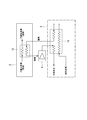
- FIG. 1 shows a carbon dioxide liquefying apparatus of this embodiment.
- the carbon dioxide liquefying apparatus 1 in this embodiment is provided in a plant such as a power plant or a gasification plant including a coal gasification furnace, for example.
- a large amount of carbon dioxide (CO2 gas) is contained in the generated gas or exhaust gas of these plants.
- the plant of this embodiment has the equipment which isolate
- the carbon dioxide liquefaction apparatus 1 is a carbon dioxide liquefaction unit that liquefies carbon dioxide by exchanging heat as part of a gaseous cold heat source used and manufactured in the cold heat source generation plant P. 2 is provided.
- Carbon dioxide supplied to the carbon dioxide liquefying unit 2 is supplied from a carbon dioxide separation and recovery device (not shown).
- the carbon dioxide separation and recovery device separates and recovers carbon dioxide from a mixed gas containing carbon dioxide.
- the carbon dioxide liquefying apparatus 1 of this embodiment the low-pressure gaseous carbon dioxide recovered by the carbon dioxide separation and recovery apparatus is pressurized to a carbon dioxide liquefying pressure by a gas compressor (not shown), and then carbon dioxide is converted into the above-mentioned carbon dioxide. After liquefying by the carbon liquefaction unit 2, the liquefied carbon dioxide is pressurized to a high pressure state by a booster pump (not shown).
- the pressure of carbon dioxide can be increased with less power than the pressure increased by the gas compressor to the high pressure state.
- the gas compressor may be omitted if the pressure of carbon dioxide recovered by the carbon dioxide separation and recovery device is equal to or higher than the liquefaction pressure of carbon dioxide.
- the cold heat source generation plant P includes an air deep cold separation unit 3.
- the air cryogenic separation unit 3 cryogenically separates oxygen from the raw material air that is the raw material gas.
- the oxygen that has been cryogenically separated by the air cryogenic separation unit 3 is used for cooling and liquefying the raw material air, and then sent to an oxygen gas compressor (not shown) or the like, for example, to a gasification furnace or a boiler. Supplied.
- the air cryogenic separation unit 3 supplies the low temperature gaseous nitrogen separated by cryogenic separation used for cooling the raw material air to the carbon dioxide liquefaction unit 2.
- the carbon dioxide liquefying unit 2 exchanges heat between gaseous nitrogen supplied from the air cryogenic separation unit 3 and gaseous carbon dioxide collected by the carbon dioxide separation and recovery device.
- the carbon dioxide liquefying apparatus 1 further includes a nitrogen gas expander 4.
- the nitrogen gas expander 4 expands gaseous nitrogen that has exchanged heat with carbon dioxide in the carbon dioxide liquefying unit 2. And the nitrogen gas expander 4 collect
- the nitrogen gas expander 4 rapidly expands the gaseous nitrogen used in the carbon dioxide liquefying unit 2 as a cold heat source, and lowers the temperature of the gaseous nitrogen to near the temperature before heat exchange is performed by the carbon dioxide liquefying unit 2. .
- the gaseous nitrogen whose temperature has been lowered by the nitrogen gas expander 4 is returned to the air cryogenic separation unit 3. This gaseous nitrogen is used as a cold heat source for cooling the raw material air in the process of deep-separating the raw material air in the air cryogenic separation unit 3.
- the air cryogenic separation unit 3 includes a heat exchanger 11.
- the heat exchanger 11 performs heat exchange using nitrogen, oxygen, air expanded by an air expander or the like separated inside the air cryogenic separation unit 3 as a cold heat source to liquefy the raw material air.
- the air cryogenic separation unit 3 separates the raw material air cooled by the heat exchanger 11 into liquid oxygen, liquid nitrogen, gaseous nitrogen, gaseous oxygen, and the like.
- Oxygen is appropriately supplied to, for example, the heat exchanger 11, the above-described coal gasification furnace, a boiler, and the like.
- the gaseous nitrogen is supplied to the carbon dioxide liquefying unit 2 via the heat exchanger 11.
- the carbon dioxide liquefying unit 2 includes a carbon dioxide condenser 15 for cooling and liquefying gaseous carbon dioxide.
- the carbon dioxide condenser 15 is supplied with gaseous nitrogen as a cold heat source from the air cryogenic separation unit 3.
- the temperature of gaseous nitrogen supplied to the carbon dioxide condenser 15 is, for example, higher than the temperature at which carbon dioxide does not solidify and lower than the liquefaction temperature of carbon dioxide.
- the liquid carbon dioxide liquefied by heat exchange with liquid nitrogen in the carbon dioxide condenser 15 is supplied to a boosting system such as the above-described booster pump (not shown).
- the pressurization system (not shown) downstream of the carbon dioxide liquefying unit 2 adjusts the temperature of the liquid carbon dioxide so that the downstream process (not shown) requires it, and the carbon dioxide is supplied to the downstream process. Send out.
- the gaseous nitrogen that has undergone heat exchange with the raw material air by the heat exchanger 11 is released into the atmosphere through a further heat exchange step in the air cryogenic separation process or used in other processes.
- the gaseous nitrogen obtained by the air cryogenic separation unit 3 can be used as a gaseous refrigerant (cold heat source) for cooling the raw air. Furthermore, when the nitrogen gas expander 4 expands the gaseous nitrogen after heat exchange with the carbon dioxide by the carbon dioxide liquefying unit 2, energy can be recovered and the temperature of the gaseous nitrogen can be lowered by the expansion. Furthermore, if the temperature of the gaseous nitrogen at the outlet of the nitrogen gas expander 4 is necessary in the air cryogenic separation unit 3, the temperature can be lowered to the temperature before the heat exchange with the carbon dioxide by the nitrogen gas expander 4.
- the gaseous nitrogen can be converted into various materials such as a raw material gas in the same manner as a general air cryogenic separation unit that does not exchange heat with carbon dioxide. Can be used for cooling.
- the power required for liquefying carbon dioxide is low compared with the case where a cold heat source used for cooling and liquefying carbon dioxide is produced by a dedicated refrigeration system such as a propane refrigeration system.
- the present invention is not limited to the above configuration, and for example, it may be used as power for a compressor or a pump (not shown) in the air separation device.
- the present invention is not limited to the above configuration, and for example, separated oxygen may be used as a cold heat source for cooling carbon dioxide.
- separated oxygen may be used as a cold heat source for cooling carbon dioxide.
- liquid oxygen is first vaporized, and then the vaporized gaseous oxygen is converted into carbon dioxide by a carbon dioxide condenser 15 in the same manner as in the case of using liquid nitrogen as a cold heat source. Heat exchange.
- gaseous oxygen after heat exchange with carbon dioxide is expanded by an oxygen gas expander (corresponding to the nitrogen gas expander 4), and then the expanded gaseous oxygen is heat exchanged with the raw material air by the heat exchanger 11.
- an oxygen gas expander corresponding to the nitrogen gas expander 4
- gaseous oxygen whose temperature has been raised by heat exchange with the raw material air is supplied to a gasification furnace or the like.
- the high temperature gas discharged from the compressor 10 and gas compressor (not shown) which compress raw material air is heated as a heating source.
- nitrogen and oxygen are separately used as the cold heat source
- a mixed air obtained by mixing oxygen and nitrogen produced in the air cryogenic separation unit 3 may be used as a cold heat source, or this mixed air may be used in appropriate combination with the nitrogen and oxygen.
- the mixed air after heat exchange with carbon dioxide is expanded by a gas expander for mixed air (corresponding to the nitrogen gas expander 4). And what is necessary is just to send in the heat exchanger 11 and heat-exchange the mixed air by which temperature fall was performed simultaneously with energy recovery.
- the gaseous nitrogen generated by the air cryogenic separation unit 3 is supplied to the carbon dioxide liquefaction unit 2 via the heat exchanger 11 .
- the carbon dioxide liquefying unit 2 may be supplied without going through the vessel 11.
- the number of stages of the nitrogen gas expander 4 may be set to a plurality of stages according to the pressure of the gaseous nitrogen vaporized by the evaporator 14. More specifically, a plurality of combinations of the nitrogen gas expander 4 and the carbon dioxide condenser 15 may be connected in series. In this case, the gaseous nitrogen expanded by the most upstream first stage nitrogen gas expander 4 is again heat exchanged with carbon dioxide by the carbon dioxide condenser 15 and then expanded again by the second stage nitrogen gas expander 4.
- the gaseous nitrogen expanded by the second stage nitrogen gas expander 4 is supplied to the heat exchanger 11.
- the nitrogen gas expander 4 is provided in three or more stages, the above process is repeated. The same applies to the case where the above-described oxygen or mixed gas is used as the cold heat source.
- Heat exchange may be performed with high-temperature carbon dioxide or high-temperature raw material air discharged from a compressor (not shown).
- the cold heat source generation plant P includes the air cryogenic separation unit 3 that generates the cold heat source.
- the present invention is not limited to this.
- the cold heat source may be generated by a method other than air separation.
- the carbon dioxide liquefying apparatus 1 provided in a plant such as a power plant that performs combined power generation including an oxygen-blown coal gasification furnace has been described as an example, but the present invention is not limited thereto.
- the carbon dioxide liquefying apparatus of the present invention can be applied to any plant that includes the cold heat source generation plant P and discharges carbon dioxide.
- the carbon dioxide liquefying apparatus 1 used in the middle of the process of generating high-pressure carbon dioxide has been described as an example.
- the carbon dioxide liquefying apparatus of the present invention is not limited to one that generates liquid carbon dioxide in the process of bringing carbon dioxide into a high pressure state.
- the present invention can also be applied to a carbon dioxide liquefaction apparatus for the final purpose of producing liquid carbon dioxide.
- the present invention is applicable to a carbon dioxide liquefaction apparatus including a carbon dioxide liquefaction unit that liquefies carbon dioxide by exchanging heat between the gaseous refrigerant sent from the cold heat source generation unit and carbon dioxide.
Landscapes
- Engineering & Computer Science (AREA)
- Physics & Mathematics (AREA)
- Mechanical Engineering (AREA)
- Thermal Sciences (AREA)
- General Engineering & Computer Science (AREA)
- Chemical & Material Sciences (AREA)
- Chemical Kinetics & Catalysis (AREA)
- Organic Chemistry (AREA)
- Inorganic Chemistry (AREA)
- Separation By Low-Temperature Treatments (AREA)
- Carbon And Carbon Compounds (AREA)
Abstract
Description
例えば、特許文献1には、石炭火力発電所等において、酸素燃焼ボイラシステムを用いて排出ガスに含まれる二酸化炭素の濃度を高めて液化分離する技術が記載されている。
そこで、上記特許文献2には、燃料電池の排出ガスの排熱を用いて駆動する吸収冷凍機を設けて気体二酸化炭素の液化に係るエネルギーの低減を図る技術が提案されている。
一方で、二酸化炭素を液化するために必要な冷熱源がある場合には、回収された気体の二酸化炭素を液化圧力まで圧縮後、その冷熱源を用いて冷却液化し、液化された二酸化炭素をポンプによって要求圧力まで低動力にて圧縮することができる。そのため、上記ガスコンプレッサーを用いる場合よりも低動力化を図ることが可能である。
図1は、この実施形態の二酸化炭素液化装置を示している。
この実施形態における二酸化炭素液化装置1は、例えば、石炭ガス化炉などを備える発電プラントやガス化プラント等のプラントに設けられる。これらプラントの生成ガスまたは排出ガスには、多量の二酸化炭素(CO2ガス)が含まれる。この実施形態のプラントは、生成ガスまたは排出ガスに含まれる二酸化炭素を分離して高圧状態に変化させる設備を有している。
空気深冷分離ユニット3は、熱交換器11によって冷却された原料空気を、液体酸素、液体窒素、および、気体窒素、気体酸素などに分離させる。酸素は、例えば、熱交換器11、上述した石炭ガス化炉、ボイラーなどに適宜供給される。また、気体窒素は、熱交換器11を介して二酸化炭素液化部2に供給される。
2 二酸化炭素液化部
3 空気深冷分離ユニット
4 窒素ガスエキスパンダー
11 熱交換器
15 二酸化炭素コンデンサー
Claims (5)
- 冷熱源生成プラントで使用および製造される気体状態の冷熱源の一部を冷媒として熱交換させることで、二酸化炭素を含むガスから分離回収された二酸化炭素を液化させる二酸化炭素液化部と、
前記二酸化炭素液化部で二酸化炭素と熱交換した気体冷媒を膨張させることでエネルギーを取り出すと同時に、前記気体冷媒を温度低下させるエネルギー回収部と、を備え、
前記エネルギー回収部は、温度低下された前記気体冷媒を前記冷熱源生成プラントに戻す二酸化炭素液化装置。 - 請求項1に記載した二酸化炭素液化装置であって、
前記エネルギー回収部は、
前記冷熱源生成プラントで使用するために必要な温度まで前記気体冷媒の温度を低下させる二酸化炭素液化装置。 - 請求項1又は2に記載した二酸化炭素液化装置であって、
前記冷熱源生成プラントは、原料空気を少なくとも酸素および窒素に分離可能な空気深冷分離ユニットを備える二酸化炭素液化装置。 - 請求項3に記載した二酸化炭素液化装置であって、
前記空気深冷分離ユニットは、前記エネルギー回収部によって温度低下された前記気体冷媒を用いて熱交換を行う熱交換部を備える二酸化炭素液化装置。 - 請求項4に記載した二酸化炭素液化装置であって、
前記エネルギー回収部と前記熱交換部との組み合わせを複数組直列に接続して備える二酸化炭素液化装置。
Priority Applications (5)
| Application Number | Priority Date | Filing Date | Title |
|---|---|---|---|
| EP13875571.5A EP2960606A4 (en) | 2013-02-25 | 2013-02-25 | CARBON DIOXIDE LIQUEFACTION DEVICE |
| US14/759,000 US20150345859A1 (en) | 2013-02-25 | 2013-02-25 | Carbon dioxide liquefaction device |
| JP2015501222A JP5932127B2 (ja) | 2013-02-25 | 2013-02-25 | 二酸化炭素液化装置 |
| PCT/JP2013/054736 WO2014128959A1 (ja) | 2013-02-25 | 2013-02-25 | 二酸化炭素液化装置 |
| CN201380070412.6A CN104937358B (zh) | 2013-02-25 | 2013-02-25 | 二氧化碳液化装置 |
Applications Claiming Priority (1)
| Application Number | Priority Date | Filing Date | Title |
|---|---|---|---|
| PCT/JP2013/054736 WO2014128959A1 (ja) | 2013-02-25 | 2013-02-25 | 二酸化炭素液化装置 |
Publications (1)
| Publication Number | Publication Date |
|---|---|
| WO2014128959A1 true WO2014128959A1 (ja) | 2014-08-28 |
Family
ID=51390782
Family Applications (1)
| Application Number | Title | Priority Date | Filing Date |
|---|---|---|---|
| PCT/JP2013/054736 Ceased WO2014128959A1 (ja) | 2013-02-25 | 2013-02-25 | 二酸化炭素液化装置 |
Country Status (5)
| Country | Link |
|---|---|
| US (1) | US20150345859A1 (ja) |
| EP (1) | EP2960606A4 (ja) |
| JP (1) | JP5932127B2 (ja) |
| CN (1) | CN104937358B (ja) |
| WO (1) | WO2014128959A1 (ja) |
Families Citing this family (7)
| Publication number | Priority date | Publication date | Assignee | Title |
|---|---|---|---|---|
| US10137406B2 (en) * | 2015-06-11 | 2018-11-27 | Hamilton Sundstrand Corporation | Temperature controlled nitrogen generation system |
| JP7412073B2 (ja) * | 2018-03-29 | 2024-01-12 | 川崎重工業株式会社 | 液体水素製造設備及び水素ガス製造設備 |
| CN109080995B (zh) * | 2018-10-10 | 2024-05-07 | 惠州市华达通气体制造股份有限公司 | 一种液体二氧化碳储罐气相外回收装置 |
| IT202000023140A1 (it) * | 2020-10-01 | 2022-04-01 | Saipem Spa | Processo di generazione di potenza che impiega un combustibile, aria e/o ossigeno liquidi a zero emissioni di co2 |
| CA3195724A1 (en) * | 2022-04-12 | 2023-10-12 | Decarbtek Global Corp. | Methods and systems for cryogenically separating carbon dioxide and hydrogen from a syngas stream |
| CN114877619B (zh) * | 2022-06-07 | 2024-06-18 | 上海齐耀螺杆机械有限公司 | 二氧化碳的液化系统及液化方法 |
| WO2024119271A1 (en) * | 2022-12-08 | 2024-06-13 | Foundation Renewable Carbon Inc. | Liquefaction apparatus and method using a by-product of an adjacent air separation unit as a cooling medium |
Citations (7)
| Publication number | Priority date | Publication date | Assignee | Title |
|---|---|---|---|---|
| JP3001060U (ja) * | 1994-02-15 | 1994-08-16 | 岩谷産業株式会社 | 産業排気ガスからの炭酸ガス回収液化装置 |
| JP2009270753A (ja) | 2008-05-07 | 2009-11-19 | Hitachi Ltd | 酸素燃焼ボイラシステム,微粉炭燃焼ボイラの改造方法,酸素燃焼ボイラシステムの制御装置及びその制御方法 |
| JP2010184994A (ja) | 2009-02-12 | 2010-08-26 | Chugoku Electric Power Co Inc:The | 石炭ガス化ガスからの二酸化炭素回収システム |
| JP2010209215A (ja) * | 2009-03-10 | 2010-09-24 | Chugoku Electric Power Co Inc:The | ガス分離方法 |
| JP2011141967A (ja) | 2010-01-05 | 2011-07-21 | Chugoku Electric Power Co Inc:The | 発電システム |
| JP2011529434A (ja) | 2008-07-31 | 2011-12-08 | ビーピー オルタネイティブ エナジー インターナショナル リミテッド | 二酸化炭素及び水素の分離 |
| JP2013087747A (ja) * | 2011-10-21 | 2013-05-13 | Chugoku Electric Power Co Inc:The | 発電システム |
Family Cites Families (13)
| Publication number | Priority date | Publication date | Assignee | Title |
|---|---|---|---|---|
| US3400547A (en) * | 1966-11-02 | 1968-09-10 | Williams | Process for liquefaction of natural gas and transportation by marine vessel |
| JP2566337B2 (ja) * | 1990-09-11 | 1996-12-25 | 三菱重工業株式会社 | Co▲下2▼ガスの液化方法 |
| JP2566338B2 (ja) * | 1990-09-21 | 1996-12-25 | 三菱重工業株式会社 | Co▲下2▼液化装置 |
| GB9105478D0 (en) * | 1991-03-15 | 1991-05-01 | Air Prod & Chem | Carbon dioxide and acid gas removal and recovery process for fossil fuel fired power plants |
| US5321953A (en) * | 1993-05-10 | 1994-06-21 | Praxair Technology, Inc. | Cryogenic rectification system with prepurifier feed chiller |
| US5572861A (en) * | 1995-04-12 | 1996-11-12 | Shao; Yulin | S cycle electric power system |
| US6070431A (en) * | 1999-02-02 | 2000-06-06 | Praxair Technology, Inc. | Distillation system for producing carbon dioxide |
| DE102004046341A1 (de) * | 2004-09-24 | 2006-03-30 | Linde Ag | Verfahren zum Verdichten eines Erdgasstromes |
| EP1767884A1 (en) * | 2005-09-23 | 2007-03-28 | L'Air Liquide Société Anon. à Directoire et Conseil de Surveillance pour l'Etude et l'Exploitation des Procédés Georges Claude | Process and apparatus for the separation of air by cryogenic distillation |
| US7819951B2 (en) * | 2007-01-23 | 2010-10-26 | Air Products And Chemicals, Inc. | Purification of carbon dioxide |
| US20120174621A1 (en) * | 2011-01-06 | 2012-07-12 | General Electric Company | Carbon dioxide liquefaction system |
| US20130111948A1 (en) * | 2011-11-04 | 2013-05-09 | Air Products And Chemicals, Inc. | Purification of Carbon Dioxide |
| CN102538398B (zh) * | 2012-02-09 | 2013-11-06 | 杭州杭氧股份有限公司 | 一种含氮氧煤矿瓦斯提纯分离液化工艺及提纯分离液化系统 |
-
2013
- 2013-02-25 JP JP2015501222A patent/JP5932127B2/ja not_active Expired - Fee Related
- 2013-02-25 US US14/759,000 patent/US20150345859A1/en not_active Abandoned
- 2013-02-25 CN CN201380070412.6A patent/CN104937358B/zh not_active Expired - Fee Related
- 2013-02-25 EP EP13875571.5A patent/EP2960606A4/en not_active Withdrawn
- 2013-02-25 WO PCT/JP2013/054736 patent/WO2014128959A1/ja not_active Ceased
Patent Citations (7)
| Publication number | Priority date | Publication date | Assignee | Title |
|---|---|---|---|---|
| JP3001060U (ja) * | 1994-02-15 | 1994-08-16 | 岩谷産業株式会社 | 産業排気ガスからの炭酸ガス回収液化装置 |
| JP2009270753A (ja) | 2008-05-07 | 2009-11-19 | Hitachi Ltd | 酸素燃焼ボイラシステム,微粉炭燃焼ボイラの改造方法,酸素燃焼ボイラシステムの制御装置及びその制御方法 |
| JP2011529434A (ja) | 2008-07-31 | 2011-12-08 | ビーピー オルタネイティブ エナジー インターナショナル リミテッド | 二酸化炭素及び水素の分離 |
| JP2010184994A (ja) | 2009-02-12 | 2010-08-26 | Chugoku Electric Power Co Inc:The | 石炭ガス化ガスからの二酸化炭素回収システム |
| JP2010209215A (ja) * | 2009-03-10 | 2010-09-24 | Chugoku Electric Power Co Inc:The | ガス分離方法 |
| JP2011141967A (ja) | 2010-01-05 | 2011-07-21 | Chugoku Electric Power Co Inc:The | 発電システム |
| JP2013087747A (ja) * | 2011-10-21 | 2013-05-13 | Chugoku Electric Power Co Inc:The | 発電システム |
Non-Patent Citations (1)
| Title |
|---|
| See also references of EP2960606A4 |
Also Published As
| Publication number | Publication date |
|---|---|
| EP2960606A4 (en) | 2016-09-21 |
| US20150345859A1 (en) | 2015-12-03 |
| CN104937358B (zh) | 2017-05-10 |
| JP5932127B2 (ja) | 2016-06-08 |
| EP2960606A1 (en) | 2015-12-30 |
| JPWO2014128959A1 (ja) | 2017-02-02 |
| CN104937358A (zh) | 2015-09-23 |
Similar Documents
| Publication | Publication Date | Title |
|---|---|---|
| JP5932127B2 (ja) | 二酸化炭素液化装置 | |
| CN109690215B (zh) | 工业气体场所与液氢生产的一体化 | |
| CN110701870B (zh) | 一种利用lng冷能的空分装置和方法 | |
| US10655913B2 (en) | Method for energy storage with co-production of peaking power and liquefied natural gas | |
| CN113286977B (zh) | 用于液化原料气的冷却方法 | |
| JP2014522477A (ja) | 天然ガスの液化プロセス | |
| JP2009529648A5 (ja) | ||
| KR101669729B1 (ko) | Lng냉열이용 팽창기체 흡입식 공기액화장치 | |
| EP1636531A1 (en) | A refrigeration process and the production of liquefied natural gas | |
| JP2014515801A5 (ja) | ||
| US20150192065A1 (en) | Process and apparatus for generating electric energy | |
| JP2015501410A (ja) | Lng生産のための多窒素膨張プロセス | |
| JP3647028B2 (ja) | 液体水素の製造方法および液体水素の製造設備 | |
| CN101539362A (zh) | 一种考虑总能系统的多级膨胀分布式天然气液化系统 | |
| US20230332833A1 (en) | Process for Producing Liquefied Hydrogen | |
| Naquash et al. | Hydrogen enrichment by CO2 anti-sublimation integrated with triple mixed refrigerant-based liquid hydrogen production process | |
| CN224126934U (zh) | 一种利用双级膜分离技术高效制备液氮的系统 | |
| JP4979138B2 (ja) | ドライアイス製造方法とその装置 | |
| JP6092804B2 (ja) | 空気液化分離方法及び装置 | |
| JP2004150685A (ja) | 窒素製造設備及びタービン発電設備 | |
| US11566841B2 (en) | Cryogenic liquefier by integration with power plant | |
| US11913718B2 (en) | Argon and power production by integration with power plant | |
| US11359858B2 (en) | Method for liquefying ammonia | |
| CN107429967B (zh) | 使用从液化天然气的蒸发中获得的冷能回收来液化氮的设备 | |
| KR20240146280A (ko) | 이산화탄소 포집 시스템 |
Legal Events
| Date | Code | Title | Description |
|---|---|---|---|
| 121 | Ep: the epo has been informed by wipo that ep was designated in this application |
Ref document number: 13875571 Country of ref document: EP Kind code of ref document: A1 |
|
| ENP | Entry into the national phase |
Ref document number: 2015501222 Country of ref document: JP Kind code of ref document: A |
|
| WWE | Wipo information: entry into national phase |
Ref document number: 14759000 Country of ref document: US Ref document number: 2013875571 Country of ref document: EP |
|
| NENP | Non-entry into the national phase |
Ref country code: DE |