WO2014129089A1 - 内視鏡用対物光学系及び撮像装置 - Google Patents
内視鏡用対物光学系及び撮像装置 Download PDFInfo
- Publication number
- WO2014129089A1 WO2014129089A1 PCT/JP2013/085015 JP2013085015W WO2014129089A1 WO 2014129089 A1 WO2014129089 A1 WO 2014129089A1 JP 2013085015 W JP2013085015 W JP 2013085015W WO 2014129089 A1 WO2014129089 A1 WO 2014129089A1
- Authority
- WO
- WIPO (PCT)
- Prior art keywords
- lens
- optical system
- objective optical
- image
- endoscope objective
- Prior art date
- Legal status (The legal status is an assumption and is not a legal conclusion. Google has not performed a legal analysis and makes no representation as to the accuracy of the status listed.)
- Ceased
Links
Images











Classifications
-
- G—PHYSICS
- G02—OPTICS
- G02B—OPTICAL ELEMENTS, SYSTEMS OR APPARATUS
- G02B23/00—Telescopes, e.g. binoculars; Periscopes; Instruments for viewing the inside of hollow bodies; Viewfinders; Optical aiming or sighting devices
- G02B23/24—Instruments or systems for viewing the inside of hollow bodies, e.g. fibrescopes
- G02B23/2407—Optical details
- G02B23/2423—Optical details of the distal end
- G02B23/243—Objectives for endoscopes
-
- A—HUMAN NECESSITIES
- A61—MEDICAL OR VETERINARY SCIENCE; HYGIENE
- A61B—DIAGNOSIS; SURGERY; IDENTIFICATION
- A61B1/00—Instruments for performing medical examinations of the interior of cavities or tubes of the body by visual or photographical inspection, e.g. endoscopes; Illuminating arrangements therefor
- A61B1/00064—Constructional details of the endoscope body
- A61B1/00071—Insertion part of the endoscope body
- A61B1/0008—Insertion part of the endoscope body characterised by distal tip features
- A61B1/00096—Optical elements
-
- A—HUMAN NECESSITIES
- A61—MEDICAL OR VETERINARY SCIENCE; HYGIENE
- A61B—DIAGNOSIS; SURGERY; IDENTIFICATION
- A61B1/00—Instruments for performing medical examinations of the interior of cavities or tubes of the body by visual or photographical inspection, e.g. endoscopes; Illuminating arrangements therefor
- A61B1/00163—Optical arrangements
- A61B1/00188—Optical arrangements with focusing or zooming features
-
- G—PHYSICS
- G02—OPTICS
- G02B—OPTICAL ELEMENTS, SYSTEMS OR APPARATUS
- G02B13/00—Optical objectives specially designed for the purposes specified below
- G02B13/04—Reversed telephoto objectives
-
- G—PHYSICS
- G02—OPTICS
- G02B—OPTICAL ELEMENTS, SYSTEMS OR APPARATUS
- G02B23/00—Telescopes, e.g. binoculars; Periscopes; Instruments for viewing the inside of hollow bodies; Viewfinders; Optical aiming or sighting devices
- G02B23/24—Instruments or systems for viewing the inside of hollow bodies, e.g. fibrescopes
- G02B23/2407—Optical details
- G02B23/2446—Optical details of the image relay
-
- G—PHYSICS
- G02—OPTICS
- G02B—OPTICAL ELEMENTS, SYSTEMS OR APPARATUS
- G02B27/00—Optical systems or apparatus not provided for by any of the groups G02B1/00 - G02B26/00, G02B30/00
- G02B27/10—Beam splitting or combining systems
- G02B27/1066—Beam splitting or combining systems for enhancing image performance, like resolution, pixel numbers, dual magnifications or dynamic range, by tiling, slicing or overlapping fields of view
Definitions
- the present invention relates to an endoscope objective optical system, and particularly to an endoscope objective optical system having a long back focus.
- Patent Document 1 and Patent Document 2 have been proposed.
- an optical member is disposed between the objective lens and its imaging surface.
- Patent Document 1 includes an optical path bending prism.
- a spectroscopic element as an optical member is arranged.
- the depth of field tends to be narrowed due to high image quality of the image sensor.
- the working distance (WD) is changed for the purpose of securing a wide observation depth.
- An endoscope objective lens having a focusing function that corrects the movement of the focal position and keeps it constant has also been proposed.
- the present invention has been made in view of the above-described circumstances, and an optical member such as a polarizing prism can be disposed, and the aberration is not easily affected by a manufacturing error, and the fluctuation of the aberration during focusing is small.
- An object of the present invention is to provide a long objective optical system for an endoscope.
- One aspect of the present invention includes, in order from the object side to the image side, a front group having a negative refractive power, a focusing lens, and a rear group having a positive refractive power, and the front group and the rear group are on the optical axis.
- the objective optical system for an endoscope that satisfies the following conditional expressions (1) and (2) is provided. 4 ⁇ FB / FL (1) FL /
- FB is the back focus of the entire system of the endoscope objective optical system, and is the distance from the most image side lens surface of the rear group to the back focal position of the entire system.
- FL is the focal length of the entire endoscope objective optical system
- fc is the focal length of the focusing lens
- is its absolute value.
- the focusing lens by satisfying the above conditional expression, it is possible to dispose an optical member such as a polarizing prism, and by defining the focal length of the focusing lens, fluctuations in aberration due to manufacturing errors and aberrations due to focusing can be reduced. Suppress. Specifically, it is possible to suppress the aberration due to the manufacturing error and reduce the influence on the optical performance deterioration, for example, to suppress one-sided blur. In addition, it is possible to suppress fluctuations in aberration due to focusing, thereby reducing fluctuations in astigmatism, and to prevent the image surface from easily falling to the minus side on the side where the working distance is short.
- the focusing lens has a weak refractive power, positive or negative.
- the working lens when the focusing lens has a positive refractive index and the working distance changes from the long side toward the short side, the working lens is moved to the image side to move the working distance to the short side. It is preferable to focus.
- the working lens when the focusing lens has a negative refractive index and the working distance changes from the long side toward the short side, the working lens is moved to the object side so that the working distance is shortened. It is preferable to focus.
- the endoscope objective optical system one imaging element disposed in the vicinity of the imaging position of the endoscope objective optical system, the objective lens, and the imaging
- a splitting element disposed between the element and splitting the light flux from the objective lens into two light fluxes, a reflected light flux and a transmitted light flux; a first reflecting member for folding back and reflecting the reflected light flux; A second reflecting member for reflecting the transmitted light beam, and images the light beam reflected by the first reflecting member through the splitting element in a first region of the imaging element, and the second reflecting member.
- An image pickup apparatus is provided that forms an image of the light flux reflected at the second region different from the first region of the image sensor.
- the above-described endoscope objective optical system can be provided with an optical member, the aberration is not easily affected by a manufacturing error, and the variation in aberration during focusing is small, and the endoscope has a long back focus.
- the objective optical system for an imaging device By applying the objective optical system for an imaging device to an imaging device, a high-quality subject image can be acquired.
- an optical member such as a polarizing prism with a long back focus, and it is possible to reduce aberration fluctuations during focusing because aberrations are not easily affected by manufacturing errors. .
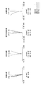
- FIG. 4 is an aberration curve diagram in the normal observation state of the objective optical system in FIG. It is an aberration curve figure in the short distance observation state of the objective optical system of FIG. 3 (B). It is sectional drawing which shows the whole structure of the objective optical system which concerns on Example 2 of this invention.
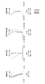
- FIG. 8 is an aberration curve diagram of the objective optical system in FIG. 7A in a normal observation state. It is an aberration curve figure in the short distance state of the objective optical system of Drawing 7 (B).
- FIG. 12 is an aberration curve diagram of the objective optical system in FIG.
- FIG. 11A in a normal observation state. It is an aberration curve figure in the short distance observation state of the objective optical system of Drawing 11 (B). It is sectional drawing which shows the whole structure of the objective optical system which concerns on Example 4 of this invention. It is sectional drawing which shows the whole structure of the objective optical system which concerns on Example 4 of this invention, (A) each shows a normal observation state, (B) shows a short-distance observation state.
- FIG. 16 is an aberration curve diagram of the objective optical system in FIG. 15A in a normal observation state. It is an aberration curve figure in the short distance observation state of the objective optical system of Drawing 15 (B).
- FIG. 19 is an aberration curve diagram in a normal observation state of the objective optical system in FIG.
- FIG. 19B is an aberration curve diagram in the short-distance observation state of the objective optical system in FIG.
- FIG. 23 is an aberration curve diagram of the objective optical system in FIG.
- FIG. 23 is an aberration curve diagram in the short-distance observation state of the objective optical system in FIG. It is sectional drawing which shows the whole structure of the objective optical system which concerns on Example 7 of this invention. It is sectional drawing which shows the whole structure of the objective optical system which concerns on Example 7 of this invention, (A) shows a normal observation state, respectively, (B) shows a short-distance observation state.
- FIG. 27 is an aberration curve diagram in the normal observation state of the objective optical system in FIG.
- FIG. 27 is an aberration curve diagram of the objective optical system in FIG. It is sectional drawing which shows the whole structure of the objective optical system which concerns on Example 8 of this invention.
- FIG. 8 It is sectional drawing which shows the whole structure of the objective optical system which concerns on Example 8 of this invention, (A) shows a normal observation state, respectively, (B) shows a short-distance observation state. It is an aberration curve figure in the normal observation state of the objective optical system of FIG. It is an aberration curve figure in the short distance observation state of the objective optical system of FIG.30 (B).
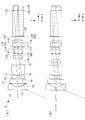
- FIG. 30 It is explanatory drawing which shows schematic structure of the imaging device concerning the 2nd Embodiment of this invention, (A) is a figure which shows the whole structure typically, (B) is the 1st and 2nd area
- FIG. 34 is a perspective view of an objective optical system, a split element, and a second reflecting member in the image pickup apparatus of FIG. 33. It is explanatory drawing which shows the structural example of the image selection part in the imaging device of FIG. 33, (A) shows the example, (B) shows another example.
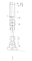
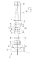
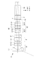
- FIG. 1 is a cross-sectional view showing the overall configuration of an endoscope objective optical system 1 according to this embodiment.
- the endoscope objective optical system 1 has, in order from the object side, a front group G1, a focusing lens F, and positive refraction having negative refractive power (hereinafter simply referred to as “negative”).
- the rear group G2 having power (hereinafter simply referred to as “positive”) is provided.
- an optical filter F On the image side of the positive rear group G2, an optical filter F, an optical prism P, and an optical member CG such as a cover glass for sealing an imaging element (not shown) are arranged.
- An imaging element is arranged in the vicinity of the image plane of the endoscope objective optical system, and constitutes the endoscope objective optical system and the imaging optical system.
- the endoscope objective optical system is configured such that the front group and the rear group are always fixed on the optical axis and satisfy the following conditional expression. 4 ⁇ FB / FL (1) FL /
- FB is the back focus of the entire system of the endoscope objective optical system, and is the distance from the most image side lens surface of the rear group to the back focal position of the entire system.
- FL is the focal length of the entire endoscope objective optical system
- fc is the focal length of the focusing lens
- is its absolute value.
- Conditional expression (1) defines the back focus. If the lower limit 4 of conditional expression (1) is not reached, it is difficult to dispose an optical member such as a polarizing prism.
- Conditional expression (2) defines the focal length of the focusing lens with respect to aberration variations due to manufacturing errors and aberration variations due to focusing.
- the focusing lens has a weak refractive power, positive or negative.
- Exceeding the upper limit of 0.1 to conditional expression (2) is not preferable because the degree of influence of decentration errors on optical performance deterioration increases. Specifically, even with the same eccentric error, one-sided blur or the like is likely to occur.
- aberration variation due to focusing increases, which is not preferable. In particular, the fluctuation of astigmatism increases, and the image surface tends to fall to the minus side when the working distance is short.
- the endoscope objective optical system 1 is more preferably configured to satisfy the following conditional expression. -3 ⁇ F_F / FL ⁇ -0.9 (3) 2.5 ⁇ F_R / FL ⁇ 5 (4) However, F_F is the focal length of the front group, and F_R is the focal length of the rear group.
- conditional expression (3) defines the focal length of the front group with respect to downsizing of the front group. If the lower limit ⁇ 3 of conditional expression (3) is not reached, the refractive power of the front group becomes insufficient, and the diameter of the first lens L1 tends to increase. It is also disadvantageous for widening the angle of view. Exceeding the upper limit of -0.9 in conditional expression (3) is advantageous for reducing the lens diameter of each lens, but off-axis high-order aberrations are likely to occur. In addition, the degree of influence of decentration error on optical performance deterioration tends to increase, which is not preferable.
- Conditional expression (4) regulates the focal length of the rear group for securing the back focus. If the lower limit of 2.5 of conditional expression (4) is not reached, the refractive power of the rear group becomes insufficient, which is disadvantageous for securing the back focus. Exceeding the upper limit of 5 to the conditional expression (4) is advantageous for securing the back focus, but it is not preferable because the lens size tends to be long.
- the focusing lens F As the focusing lens F, a lens having positive or negative refractive power can be applied. However, when the focusing lens F has positive refractive power, the working distance changes from the long side toward the short side. In this case, it is preferable that the focusing lens is moved toward the image side to focus on the side where the working distance is short.
- the focusing lens F has a negative refractive index and the working distance changes from the long side toward the short side, the focusing lens F is moved to the object side to focus on the short working distance side. Is preferred. This is because by moving the focusing lens F to the object side on the optical axis, it is possible to focus on the side where the working distance is short.
- the present invention by satisfying the above conditional expression, it is possible to dispose an optical member such as a polarizing prism, and by defining the focal length of the focusing lens, fluctuations in aberrations due to manufacturing errors and aberrations due to focusing can be reduced. Suppress. Specifically, it is possible to suppress the aberration due to the manufacturing error and reduce the influence on the optical performance deterioration, for example, to suppress one-sided blur. In addition, it is possible to suppress fluctuations in aberration due to focusing, thereby reducing fluctuations in astigmatism, and to prevent the image surface from easily falling to the minus side on the side where the working distance is short.
- the focusing lens has a positive or negative weak refractive index, that is, a refractive power.
- r is a radius of curvature (unit: mm)
- d is a surface interval (mm)
- Nd is a refractive index with respect to the d line
- Vd is an Abbe number with respect to the d line.
- Example 2 and 3 show the configuration of the endoscope objective optical system according to Example 1 of the present invention.
- FIG. 3 shows a normal observation state
- (B) shows a short-distance observation state
- light rays indicate an axial marginal ray and a principal ray having a maximum field angle.
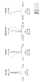
- FIG. 4 shows an aberration curve diagram in the normal observation state of the objective optical system for an endoscope according to the present example
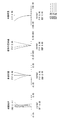
- FIG. 5 shows an aberration curve diagram in the short-distance observation state.
- the negative front group G1 includes, in order from the object side, a first lens L1 of a plano-concave lens whose object side is a plane, an infrared cut filter A CF, a second lens L2 of a biconcave lens, and a third lens L3 of a biconvex lens are provided.
- the second lens L2 and the third lens L3 are cemented lenses CL1.
- the focusing lens F includes a fourth lens L4 that is a biconvex lens and a fifth lens L5 that is a negative meniscus lens having a concave surface facing the object side.
- the cemented lens CL2 is formed by joining the fourth lens L4 and the fifth lens L5. It has become.
- the focusing lens F has a positive refractive power.
- the positive rear group G2 in order from the object side, is a sixth lens L6 having a negative meniscus lens having a concave surface facing the image side, a seventh lens L7 having a concave surface facing the image side, and an eighth lens having a biconvex lens.
- L8 a ninth lens L9 of a biconvex lens, and a tenth lens L10 of a negative meniscus lens having a concave surface facing the object side.
- the sixth lens L6 and the seventh lens L7 are cemented to form a cemented lens CL3
- the ninth lens L9 and the tenth lens L10 are cemented to form a cemented lens CL4.
- an aperture stop AS is provided between the focusing lens F and the rear group G2.
- the fourth lens L4 and the fifth lens L5 which are focusing lenses F, move on the optical axis to the image side, and focus on the side with the shorter working distance.
- Lens data of the objective optical system according to Example 1 of the present invention is shown below.
- Example 2 shows the configuration of an endoscope objective optical system according to Example 2 of the present invention.
- (A) shows a normal observation state
- (B) shows a short-distance observation state
- rays indicate an axial marginal ray and a principal ray having a maximum field angle.
- FIG. 8 shows an aberration curve diagram in the normal observation state of the objective optical system for an endoscope according to the present example
- FIG. 9 shows an aberration curve diagram in the short-distance observation state.
- the negative front group G1 includes, in order from the object side, a first lens L1 of a plano-concave lens whose object side is a plane, an infrared cut filter A CF, a second lens L2 of a biconcave lens, and a third lens L3 of a biconvex lens are provided.
- the second lens L2 and the third lens L3 are cemented lenses CL1.
- the focusing lens F includes a biconvex fourth lens L4 and a biconcave fifth lens L5, and the fourth lens L4 and the fifth lens L5 are cemented lenses CL2.
- the focusing lens F has a positive refractive power.
- the positive rear group G2 in order from the object side, is a sixth lens L6 having a negative meniscus lens having a concave surface facing the image side, a seventh lens L7 having a concave surface facing the image side, and an eighth lens having a biconvex lens.
- L8 a ninth lens L9 of a biconvex lens, and a tenth lens L10 of a negative meniscus lens having a concave surface facing the object side.
- the sixth lens L6 and the seventh lens L7 are cemented to form a cemented lens CL3
- the ninth lens L9 and the tenth lens L10 are cemented to form a cemented lens CL4.
- an aperture stop AS is provided between the focusing lens F and the rear group G2.
- the fourth lens L4 and the fifth lens L5 which are focusing lenses F, move on the optical axis to the image side, and focus on the side with the shorter working distance.
- Lens data of the objective optical system according to Example 2 of the present invention is shown below.
- FIGS. The configuration of the endoscope objective optical system 3 according to Embodiment 3 of the present invention is shown in FIGS.
- FIG. 11 shows a normal observation state
- (B) shows a short-distance observation state
- rays indicate an axial marginal ray and a principal ray having a maximum field angle
- FIG. 12 shows an aberration curve diagram of the endoscope objective optical system 3 according to the present embodiment in the normal observation state
- FIG. 13 shows an aberration curve diagram of the short-distance observation state.
- the negative front group G1 includes, in order from the object side, a first lens L1 of a plano-concave lens having a flat object side, an infrared cut filter A CF, a second lens L2 of a biconcave lens, and a third lens L3 of a biconvex lens are provided.
- the focusing lens F is a fourth lens of a positive meniscus lens having a convex surface facing the object side, and has a positive refractive power.
- the positive rear group includes a fifth lens L5 having a negative meniscus lens having a concave surface facing the image side, a sixth lens L6 having a concave meniscus lens having a concave surface facing the image side, a seventh lens L7 having a biconvex lens, and a biconvex lens. 8th lens L8, and the 9th lens L9 of the negative meniscus lens which turned the concave surface to the object side.
- the fifth lens L5 and the sixth lens L6 are cemented to be a cemented lens CL5
- the eighth lens L8 and the ninth lens L9 are cemented to be a cemented lens CL6.
- an aperture stop AS is provided between the focusing lens F and the rear group G2.
- the fourth lens which is the focusing lens F, moves on the optical axis to the image side, and focuses on the side with the shorter working distance.
- Lens data of the endoscope objective optical system 3 according to Example 3 of the present invention are shown below.
- Example 4 14 and 15 show the configuration of an endoscope objective optical system 4 according to Embodiment 4 of the present invention.
- (A) shows a normal observation state
- (B) shows a short-distance observation state
- rays indicate an axial marginal ray and a principal ray having a maximum field angle.
- FIG. 16 shows an aberration curve diagram of the endoscope objective optical system 4 according to the present embodiment in the normal observation state
- FIG. 17 shows an aberration curve diagram of the short-distance observation state.
- the negative front group G1 includes, in order from the object side, a first lens L1 of a plano-concave lens having a flat object side, an infrared cut filter A CF, a second lens L2 of a biconcave lens, and a third lens L3 of a biconvex lens are provided.
- the focusing lens F is a fourth lens of a negative meniscus lens having a concave surface directed toward the object side, and has negative refractive power.
- the positive rear group G2 in order from the object side, is a fifth lens L5 of a biconvex lens, a sixth lens L6 of a negative meniscus lens having a concave surface facing the object side, a seventh lens L7 of a biconvex lens, and a concave surface facing the object side.
- an eighth lens L8 of a negative meniscus lens is cemented to form a cemented lens CL7
- the seventh lens L7 and the eighth lens L8 are cemented to form a cemented lens CL8.
- an aperture stop AS is provided between the focusing lens F and the rear group G2.
- the fourth lens L4 which is the focusing lens F, moves on the optical axis to the object side, and focuses on the side with the short working distance.
- Lens data of the endoscope objective optical system 4 according to Example 4 of the present invention are shown below.
- FIG. 18 shows the configuration of an endoscope objective optical system 5 according to Embodiment 5 of the present invention.
- the description is abbreviate
- FIG. 18 shows a normal observation state
- (B) shows a short-distance observation state
- light rays indicate an axial marginal ray and a principal ray having a maximum field angle.
- FIG. 19 shows an aberration curve diagram of the endoscope objective optical system according to this example in the normal observation state
- FIG. 20 shows an aberration curve diagram of the short-distance observation state.
- Lens data of the objective optical system according to Example 5 of the present invention are shown below.
- Example 6 The configuration of an endoscope objective optical system 6 according to Example 6 of the present invention is shown in FIGS.
- FIG. 22 shows a normal observation state
- (B) shows a short-distance observation state
- light rays indicate an axial marginal ray and a principal ray having a maximum field angle.
- FIG. 23 shows an aberration curve diagram of the endoscope objective optical system 6 according to the present embodiment in the normal observation state
- FIG. 24 shows an aberration curve diagram of the short-distance observation state.
- the negative front group G1 includes, in order from the object side, a first lens L1 of a plane plano-concave lens, an infrared cut filter CF, A second lens L2 that is a biconcave lens and a third lens L3 that is a biconvex lens are provided.
- the focusing lens F is a fourth lens L4 that is a plano-concave lens having a concave surface directed toward the object side, and has negative refractive power.
- the positive rear group G2 in order from the object side, is a fifth lens L5 of a positive meniscus lens having a convex surface directed to the image side, an aperture stop AS, a seventh lens L7 of a planoconvex lens having a plane on the object side, and an eighth lens of a biconvex lens.
- a lens L8 and a ninth lens L9 of a negative meniscus lens having a concave surface facing the object side are provided.
- the fifth lens L5 and the sixth lens L6 are cemented to be a cemented lens CL9
- the eighth lens L8 and the ninth lens L9 are cemented to be a cemented lens CL10.
- an aperture stop AS is provided between the focusing lens F and the rear group G2.
- the fourth lens L4 which is the focusing lens F, is retracted from the optical axis, and is focused on the side with the shorter working distance.
- Lens data of the endoscope objective optical system 6 according to Example 6 of the present invention are shown below.
- Example 7 The configuration of the endoscope objective optical system 7 according to Example 7 of the present invention is shown in FIGS.
- FIG. 26 shows a normal observation state
- (B) shows a short-distance observation state
- light rays indicate an axial marginal ray and a principal ray having a maximum field angle
- FIG. 27 shows an aberration curve diagram of the endoscope objective optical system 7 according to the present embodiment in the normal observation state
- FIG. 28 shows an aberration curve diagram of the short-distance observation state.
- the negative front group G1 includes, in order from the object side, a first lens L1 of a plano-concave lens whose object side is a plane, an infrared cut filter A CF, a second lens L2 of a biconcave lens, and a third lens L3 of a positive meniscus lens having a convex surface facing the image side are provided.
- the focusing lens F is a fourth lens of a negative meniscus lens having a concave surface directed toward the object side, and has negative refractive power.
- the positive rear group G2 includes a fifth lens L5 having a positive meniscus lens having a convex surface facing the image side, a sixth lens L6 having a negative meniscus lens having a concave surface facing the object side, a seventh lens L7 having a biconvex lens, and the object side.
- An eighth lens L8, which is a negative meniscus lens with a concave surface facing the lens, is provided.
- the fifth lens L5 and the sixth lens L6 are cemented to form a cemented lens CL9
- the seventh lens L7 and the eighth lens L8 are cemented to form a cemented lens CL10.
- an aperture stop AS is provided between the focusing lens F and the rear group G2.
- the fourth lens which is a focusing lens, is retracted from the optical axis and focused on the side with the shorter working distance.
- Lens data of the endoscope objective optical system 7 according to Example 7 of the present invention are shown below.
- Example 8 The configuration of the endoscope objective optical system 8 according to Example 8 of the present invention is shown in FIGS.
- FIG. 30 (A) shows a normal observation state, (B) shows a short-distance observation state, and light rays indicate an axial marginal ray and a principal ray having a maximum field angle.
- FIG. 31 shows an aberration curve diagram in the normal observation state of the objective optical system for an endoscope according to the present example
- FIG. 32 shows an aberration curve diagram in the short distance observation state.
- the negative front group G1 includes, in order from the object side, the first lens L1 of the plano-concave lens whose object side is a plane, and the first lens L1 of the biconcave lens.
- the focusing lens F is a fourth lens L4 of a negative meniscus lens having a concave surface directed toward the object side, and has negative refractive power.
- the positive rear group 2 includes a fifth lens L5 that is a plano-convex lens having a plane on the object side, a sixth lens L6 that is a plano-concave lens having a plane on the image side, an aperture stop AS, a seventh lens L7 that is a plano-convex lens having a plane on the object side, and a biconvex lens. 8th lens L8, and the 9th lens L9 of the negative meniscus lens which turned the concave surface to the object side.
- the fifth lens L5 and the sixth lens L6 are cemented to be a cemented lens CL11
- the eighth lens L8 and the ninth lens L9 are cemented to be a cemented lens CL12.
- An infrared cut filter CF is arranged between the focusing lens F and the rear group G2.
- the fourth lens which is a focusing lens, is retracted from the optical axis and focused on the side with the shorter working distance.
- Lens data of the endoscope objective optical system 8 according to Example 8 of the present invention are shown below.
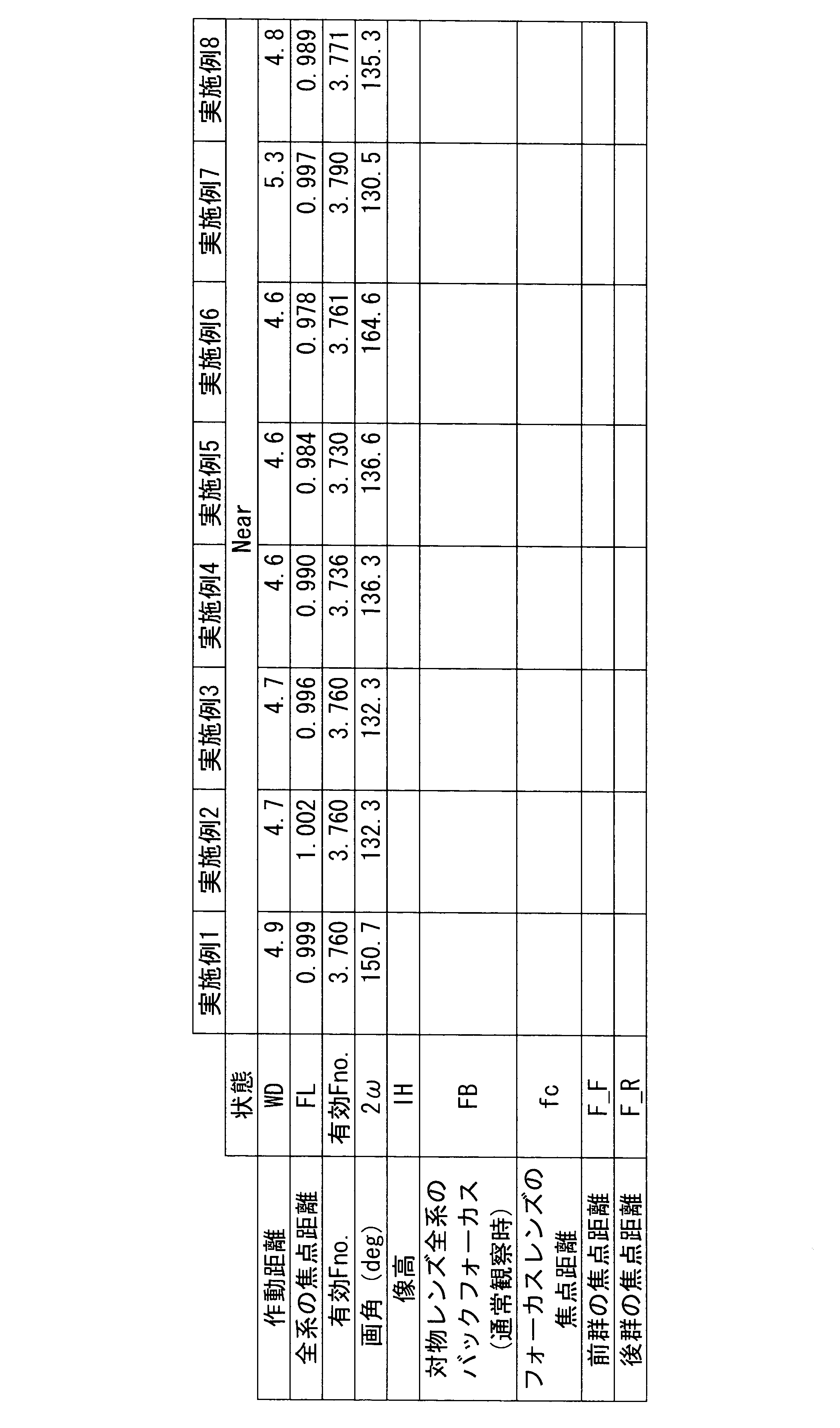
- Tables 1 to 3 show numerical values of the conditional expressions (1) to (4) in the configurations of the first to eighth embodiments.
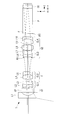
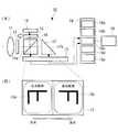
- FIG. 33 shows a schematic configuration of the imaging apparatus 10 according to the second embodiment of the present invention, (A) schematically shows the overall configuration, and (B) shows first and second regions of the imaging device. It is a figure which shows the direction of the to-be-photographed object in the image which respectively forms an image.
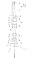
- FIG. 34 is a perspective view of the objective optical system, the dividing element, and the second reflecting member in the imaging apparatus 10 of FIG.
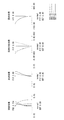
- FIG. 35 is an explanatory diagram showing a configuration example of the image selection unit in the imaging apparatus 10 of FIG. 33, (A) shows an example thereof, and (B) shows another example.
- the imaging apparatus 10 includes the objective optical system 11, the depolarization plate 12, the imaging element 13, the polarization beam splitter 14, the wave plate 15, the first reflection member 16, the second reflection member 17, and the image.
- a processing unit 18 is included.
- 19 is an image display device.
- the objective optical system 11 has a function of forming an image of a light beam from an object, and the image side is configured to be telecentric.
- the depolarization plate 12 is disposed between the objective optical system 11 and the polarization beam splitter 14.
- the image sensor 13 is composed of a rolling shutter type CMOS sensor, and is disposed in the vicinity of the imaging position of the objective optical system 11.
- the polarization beam splitter 14 is disposed on the optical path between the objective optical system 11 and the image pickup device 13 and above the first region 13a of the image pickup device 13, and the light beam from the objective optical system 11 on the polarization beam splitter surface 14a. Is divided into two light beams, a reflected light beam and a transmitted light beam.
- the polarization beam splitter 14 reflects the linearly polarized light of the S polarization component and transmits the linearly polarized light of the P polarization component.
- the wave plate 15 is composed of a ⁇ / 4 plate and is configured to be rotatable around the optical axis.
- the first reflecting member 16 is composed of a mirror, and reflects the light beam reflected by the polarization beam splitter surface 14 a and transmitted through the wave plate 15 to be reflected.
- the second reflecting member 17 is composed of a prism, and reflects the light transmitted through the polarizing beam splitter 14 by the total reflection surface 17a.
- the prism 17 may comprise a reflective surface by giving a mirror coat to the total reflection surface 17a.
- the imaging apparatus 10 forms an image of the light beam reflected by the first reflecting member 16 via the wave plate 15 and the polarization beam splitter 14 on the first region 13a of the imaging element 13, while the second The light beam reflected by the reflecting member 17 is imaged in a second region 13b different from the first region 13a in the image sensor 13.
- the image processing unit 18 is connected to the image sensor 13 and is provided in a central processing unit (not shown).
- the first image processing unit 18a, the second image processing unit 18b, the third image processing unit 18c, and the fourth An image processing unit 18d and a fifth image processing unit 18e are included.
- the first image processing unit 18a is configured to correct the orientation (rotation) of the image in the first area 13a and the image in the second area 13b.
- the orientation of the image formed in the first area 13a and the second area 13b is as shown in FIG. 33B. That is, the image formed in the first region 13a rotates 90 degrees clockwise around the center point of the first region 13a and passes through the center point of the first region 13a in the vertical direction in FIG. The orientation is rotated 180 degrees around the axis. The image formed in the second area 13b is oriented 90 degrees clockwise around the center point of the second area 13b.
- the first region 13a and the second region 13b are connected via the first image processing unit 18a.
- the image formed on each image is rotated 90 degrees counterclockwise about the center point of each region, and the image of the first region 13a passes through the center point of the first region 13a as shown in FIG.
- the mirror image is corrected by rotating it 180 degrees around the vertical axis.
- the third image processing unit 18c is configured to be able to adjust the white balance of the image of the first area 13a and the image of the second area 13b.
- the fourth image processing unit 18d is configured to be able to move (select) the center positions of the image of the first area 13a and the image of the second area 13b.
- the fifth image processing unit 18e is configured to be able to adjust the display range (magnification) of each of the image in the first area 13a and the image in the second area 13b.
- the second image processing unit 18b corresponds to the image selection unit of the present invention, compares the image in the first region 13a and the image in the second region 13b, and selects the image in the focused region as a display image. It is configured as follows.
- the second image processing unit 18b is connected to the high-pass filters 18b1a and 18b1b connected to the respective regions 13a and 13b and the high-pass filters 18b1a and 18b1b, for example, as shown in FIG.
- a comparator 18b2 and a switch 18b3 connected to the comparator 18b2 and the respective regions 13a and 13b.
- the images of the first region 13a and the second region 13b are converted into high-frequency components by the high-pass filters 18b1a and 18b1b.
- the extracted high-frequency components are compared by the comparator 18b2, and an image of a region having a high high-frequency component is selected by the switch 18b3.
- a defocus filter 18b4 connected to only one region 13a, a comparator 18b2 connected to the defocus filter 18b4 and connected to the other region 13b, A switch 18b3 connected to the region 13a and the comparator 18b2 is provided, and the image signal of the other region 13b not focused with the image signal of one region 13a defocused by the defocus filter 18b4 is output by the comparator 18b2.
- the switching unit 18b3 may be configured to select an image in the other region 13b for a matching portion and an image in the region 13a for a non-matching portion.
- the image display device 19 has a display area for displaying the image selected by the second image processing unit 18b.
- the image display device 19 may have a display area for displaying an image formed in each of the first and second areas 13a and 13b.
- the light beam from the objective optical system 11 passes through the depolarization plate 12 and enters the polarization beam splitter 14 in a state where the polarization direction is eliminated.
- the light incident on the polarization beam splitter 14 is separated into linearly polarized S-polarized light component and P-polarized light component by the polarization beam splitter surface 14a.
- the linearly polarized light beam of the S-polarized component reflected by the polarization beam splitter surface 14 a passes through the ⁇ / 4 plate 15, the polarization state is converted to circularly polarized light, and is reflected by the mirror 16.
- the light beam reflected by the mirror 16 passes through the ⁇ / 4 plate 15 again, the polarization state is converted from circularly polarized light to linearly polarized light of the P-polarized component, enters the polarizing beam splitter 14 again, and passes through the polarizing beam splitter surface 14a.
- an image is formed on the first region 13 a of the image sensor 13.
- the linearly polarized light beam of the S-polarized component that has passed through the polarization beam splitter surface 14 a when entering the polarization beam splitter 14 through the objective optical system 11 and the depolarization plate 12 is reflected by the total reflection surface 17 a of the prism 17. Then, an image is formed on the second region 13 b of the image sensor 13.
- the imaging element 13 is configured by a rolling shutter system as described above, and reads an image line by line in the direction indicated by the arrow in FIG.
- the second image processing unit 18b compares the images formed in the first region 13a and the second region 13b read out line by line, and selects the focused image as the display image. Note that the image for each line selected by the second image processing unit 18 b is synthesized and displayed on the image display device 19.
Landscapes
- Physics & Mathematics (AREA)
- Health & Medical Sciences (AREA)
- Life Sciences & Earth Sciences (AREA)
- Optics & Photonics (AREA)
- Surgery (AREA)
- General Physics & Mathematics (AREA)
- Astronomy & Astrophysics (AREA)
- Pathology (AREA)
- Public Health (AREA)
- Engineering & Computer Science (AREA)
- Biomedical Technology (AREA)
- Heart & Thoracic Surgery (AREA)
- Medical Informatics (AREA)
- Molecular Biology (AREA)
- Animal Behavior & Ethology (AREA)
- General Health & Medical Sciences (AREA)
- Radiology & Medical Imaging (AREA)
- Veterinary Medicine (AREA)
- Nuclear Medicine, Radiotherapy & Molecular Imaging (AREA)
- Biophysics (AREA)
- Lenses (AREA)
- Endoscopes (AREA)
- Studio Devices (AREA)
- Instruments For Viewing The Inside Of Hollow Bodies (AREA)
Abstract
バックフォーカスを長くして偏光プリズム等の光学部材を配置可能としながら、収差が製造誤差による影響を受けにくく、フォーカシング時の収差の変動を少なくする。物体側から像側へ順に、負の屈折力を有する前群G1、フォーカシングレンズF、正の屈折力を有する後群G2を備え、前群及び後群が、光軸上に常に固定されており、以下の条件式(1)及び(2)を満たす内視鏡用対物光学系を提供する。 4<FB/FL …(1) FL/|fc|<0.1 …(2) ただし、FBは、内視鏡用対物光学系全系のバックフォーカスであり、後群の最も像側のレンズ面から全系の後ろ側焦点位置までの距離である。また、FLは、内視鏡用対物光学系全系の焦点距離であり、fcはフォーカシングレンズの焦点距離であり、|fc|はその絶対値である。
Description
本発明は、内視鏡用対物光学系に関し、特にバックフォーカスが長い内視鏡用対物光学系に関する。
内視鏡用対物光学系において、光路内にプリズム等の光学部材を配置するために長いバックフォーカスを確保する必要がある場合がある。このような長いバックフォーカスを有する対物光学系レンズとして、例えば、特許文献1、特許文献2が提案されている。
特許文献1及び特許文献2は、何れも対物レンズとその結像面との間に光学部材を配置しており、特に特許文献1では、光路折り曲げ用プリズムを配置し、特許文献2では、分光光学部材としての分光素子を配置している。
また近年、撮像素子の高画質化により被写界深度が狭くなる傾向にあり、例えば、特許文献3のように、広い観察深度を確保することを目的として、作動距離(WD)の変化に伴う焦点位置の移動を補正し一定に保つフォーカシング機能を有する内視鏡用対物レンズも提案されている。
一方、撮像素子の高画質化に伴い、フォーカシング機能を有する内視鏡用対物光学系においても、作動距離の変動に伴うピント合わせだけでなく、フォーカシング時の収差変動を小さく抑えることがより一層重要となっている。
特許文献1及び特許文献2は、何れも対物レンズとその結像面との間に光学部材を配置しており、特に特許文献1では、光路折り曲げ用プリズムを配置し、特許文献2では、分光光学部材としての分光素子を配置している。
また近年、撮像素子の高画質化により被写界深度が狭くなる傾向にあり、例えば、特許文献3のように、広い観察深度を確保することを目的として、作動距離(WD)の変化に伴う焦点位置の移動を補正し一定に保つフォーカシング機能を有する内視鏡用対物レンズも提案されている。
一方、撮像素子の高画質化に伴い、フォーカシング機能を有する内視鏡用対物光学系においても、作動距離の変動に伴うピント合わせだけでなく、フォーカシング時の収差変動を小さく抑えることがより一層重要となっている。
しかしながら、上記した各特許文献では、バックフォーカスの長さが不十分であったり、フォーカシング機能を有しない、又は、有していても光路中にプリズム等の光学素子を配置することを想定していないため、フォーカシング時の収差変動を所望の範囲に抑えることができない。
また、上述のように、フォーカシング時の収差変動を小さく抑えることがより一層重要となっている。一方で、フォーカシングレンズの摺動性を向上させるために、ある程度の遊びを確保する必要があり、製造誤差によるフォーカシングレンズの偏心は避けられない。そして、フォーカシングレンズの偏心等の製造誤差により、収差の劣化が目立ちやすくなってしまう。
また、上述のように、フォーカシング時の収差変動を小さく抑えることがより一層重要となっている。一方で、フォーカシングレンズの摺動性を向上させるために、ある程度の遊びを確保する必要があり、製造誤差によるフォーカシングレンズの偏心は避けられない。そして、フォーカシングレンズの偏心等の製造誤差により、収差の劣化が目立ちやすくなってしまう。
本発明は、上述した事情に鑑みてなされたものであって、偏光プリズム等の光学部材を配置可能であり、収差が製造誤差による影響を受けにくく、フォーカシング時の収差の変動が少ないバックフォーカスの長い内視鏡用対物光学系を提供することを目的とする。
上記目的を達成するため、本発明は以下の手段を提供する。
本発明の一態様は、物体側から像側へ順に、負の屈折力を有する前群、フォーカシングレンズ、正の屈折力を有する後群を備え、前記前群及び前記後群が、光軸上に常に固定されており、以下の条件式(1)及び(2)を満たす内視鏡用対物光学系を提供する。
4<FB/FL …(1)
FL/|fc|<0.1 …(2)
ただし、FBは、内視鏡用対物光学系全系のバックフォーカスであり、後群の最も像側のレンズ面から全系の後ろ側焦点位置までの距離である。また、FLは、内視鏡用対物光学系全系の焦点距離であり、fcはフォーカシングレンズの焦点距離であり、|fc|はその絶対値である。
本発明の一態様は、物体側から像側へ順に、負の屈折力を有する前群、フォーカシングレンズ、正の屈折力を有する後群を備え、前記前群及び前記後群が、光軸上に常に固定されており、以下の条件式(1)及び(2)を満たす内視鏡用対物光学系を提供する。
4<FB/FL …(1)
FL/|fc|<0.1 …(2)
ただし、FBは、内視鏡用対物光学系全系のバックフォーカスであり、後群の最も像側のレンズ面から全系の後ろ側焦点位置までの距離である。また、FLは、内視鏡用対物光学系全系の焦点距離であり、fcはフォーカシングレンズの焦点距離であり、|fc|はその絶対値である。
本態様によれば、上記条件式を満たすことで、偏光プリズム等の光学部材を配置可能としながら、フォーカシングレンズの焦点距離を規定することにより、製造誤差による収差の変動とフォーカシングによる収差の変動を抑制する。具体的には、製造誤差による収差を抑制して、光学性能劣化への影響を小さくし、例えば、片ボケを抑制することができる。また、フォーカシングによる収差の変動を抑制して、非点収差の変動を小さくし、作動距離が短い側で像面がマイナス側に倒れやすくなるのを防止することができる。なお、フォーカシングレンズは正あるいは負の、弱い屈折力をもつ。
上記した態様において、以下の条件式(3)及び(4)を満たすことが好ましい。
-3<F_F/FL<-0.9 …(3)
2.5<F_R/FL<5 …(4)
ただし、F_Fは前群の焦点距離であり、F_Rは後群の焦点距離である。
-3<F_F/FL<-0.9 …(3)
2.5<F_R/FL<5 …(4)
ただし、F_Fは前群の焦点距離であり、F_Rは後群の焦点距離である。
このようにすることで、前群の屈折力を十分に保ちながら、広画角化に有利とし、軸外の高次収差を抑えつつ、偏心誤差の光学性能劣化への影響を小さくすることができる。
また、後群の屈折力を保ち、バックフォーカスを確保しつつ、レンズサイズを所望の範囲に抑えることができる。
また、後群の屈折力を保ち、バックフォーカスを確保しつつ、レンズサイズを所望の範囲に抑えることができる。
上記した態様において、前記フォーカシングレンズが、正の屈折率を有し、作動距離が長い側から短い側に向かって変化するとき、前記フォーカシングレンズを像側に移動することで作動距離が短い側にピント合わせることが好ましい。
このようにすることで、フォーカシングレンズを光軸上像側に移動することで作動距離が短い側にピント合わせることができる。
上記した態様において、前記フォーカシングレンズが、負の屈折率を有し、作動距離が長い側から短い側に向かって変化するとき、前記フォーカシングレンズを物体側に移動することで作動距離が短い側にピント合わせることが好ましい。
このようにすることで、フォーカシングレンズを光軸上物体側に移動することで作動距離が短い側にピント合わせることができる。
また、本発明の他の態様は、上記の内視鏡用対物光学系と、該内視鏡用対物光学系の結像位置近傍に配置された1つの撮像素子と、前記対物レンズと前記撮像素子との間に配置され、前記対物レンズからの光束を反射光束と透過光束の2つの光束に分割するための分割素子と、前記反射光束を折り返して反射させるための第1反射部材と、前記透過光束を反射させるための第2反射部材と、を有し、前記分割素子を介して前記第1反射部材で反射した光束を前記撮像素子における第1領域に結像させ、前記第2反射部材で反射した光束を前記撮像素子における前記第1領域とは異なる第2領域に結像させる撮像装置を提供する。
上記した内視鏡用対物光学系が、光学部材を配置可能であり、収差が製造誤差による影響を受けにくく、フォーカシング時の収差の変動が少ないバックフォーカスの長いものであることから、この内視鏡用対物光学系を撮像装置に適用することで、高品質な被写体像を取得することができる。
本発明によれば、バックフォーカスを長くして偏光プリズム等の光学部材を配置可能としながら、収差が製造誤差による影響を受けにくく、フォーカシング時の収差の変動を少なくすることができるという効果を奏する。
〔第1の実施形態〕
以下に、本発明の第1の実施形態に係る対物光学系について図面を参照して説明する。
図1は、本実施形態に係る内視鏡用対物光学系1の全体構成を示す断面図を示している。図1に示すように、内視鏡用対物光学系1は、物体側から順に、負の屈折力を有する(以下、単に「負の」という)前群G1、フォーカシングレンズF、及び正の屈折力を有する(以下、単に「正の」という)後群G2を備えている。
以下に、本発明の第1の実施形態に係る対物光学系について図面を参照して説明する。
図1は、本実施形態に係る内視鏡用対物光学系1の全体構成を示す断面図を示している。図1に示すように、内視鏡用対物光学系1は、物体側から順に、負の屈折力を有する(以下、単に「負の」という)前群G1、フォーカシングレンズF、及び正の屈折力を有する(以下、単に「正の」という)後群G2を備えている。
正の後群G2の像側には光学フィルタF、光学プリズムP、図示しない撮像素子を封止するカバーガラス等の光学部材CGを配置している。
そして、内視鏡用対物光学系の像面近傍には撮像素子が配置され、内視鏡用対物光学系と撮像光学系を構成している。
そして、内視鏡用対物光学系の像面近傍には撮像素子が配置され、内視鏡用対物光学系と撮像光学系を構成している。
内視鏡用対物光学系は、前群及び後群が光軸上に常に固定されており、以下の条件式を満足するように構成されている。
4<FB/FL …(1)
FL/|fc|<0.1 …(2)
ただし、FBは、内視鏡用対物光学系全系のバックフォーカスであり、後群の最も像側のレンズ面から全系の後ろ側焦点位置までの距離である。また、FLは、内視鏡用対物光学系全系の焦点距離であり、fcはフォーカシングレンズの焦点距離であり、|fc|はその絶対値である。
4<FB/FL …(1)
FL/|fc|<0.1 …(2)
ただし、FBは、内視鏡用対物光学系全系のバックフォーカスであり、後群の最も像側のレンズ面から全系の後ろ側焦点位置までの距離である。また、FLは、内視鏡用対物光学系全系の焦点距離であり、fcはフォーカシングレンズの焦点距離であり、|fc|はその絶対値である。
条件式(1)は、バックフォーカスを規定したものである。条件式(1)の下限4を下回ると偏光プリズム等の光学部材を配置することが困難となる。
条件式(2)は、製造誤差による収差の変動とフォーカシングによる収差の変動に関し、フォーカシングレンズの焦点距離を規定したものである。フォーカシングレンズは正あるいは負の、弱い屈折力をもつ。条件式(2)の上限0.1を超えると偏心誤差の光学性能劣化への影響度が高くなり好ましくない。具体的には、同じ偏心誤差でも片ボケ等が発生しやすくなる。またフォーカシングによる収差の変動が大きくなり好ましくない。特に、非点収差の変動が大きくなり、作動距離が短い側で像面がマイナス側に倒れやすくなる。
条件式(2)は、製造誤差による収差の変動とフォーカシングによる収差の変動に関し、フォーカシングレンズの焦点距離を規定したものである。フォーカシングレンズは正あるいは負の、弱い屈折力をもつ。条件式(2)の上限0.1を超えると偏心誤差の光学性能劣化への影響度が高くなり好ましくない。具体的には、同じ偏心誤差でも片ボケ等が発生しやすくなる。またフォーカシングによる収差の変動が大きくなり好ましくない。特に、非点収差の変動が大きくなり、作動距離が短い側で像面がマイナス側に倒れやすくなる。
また、内視鏡用対物光学系1は、以下の条件式を満足するように構成されると更に好ましい。
-3<F_F/FL<-0.9 …(3)
2.5<F_R/FL<5 …(4)
ただし、F_Fは前群の焦点距離であり、F_Rは後群の焦点距離である。
-3<F_F/FL<-0.9 …(3)
2.5<F_R/FL<5 …(4)
ただし、F_Fは前群の焦点距離であり、F_Rは後群の焦点距離である。
ここで、条件式(3)は前群の小型化に関し、前群の焦点距離を規定している。この条件式(3)の下限-3を下回ると前群の屈折力が不十分となり、第1レンズL1の径が大きくなりやすい。また広画角化に不利となる。条件式(3)の上限-0.9を超えると各レンズのレンズ径の小型化には有利となるが、軸外の高次収差が発生しやすくなる。また偏心誤差の光学性能劣化への影響度が高くなりやすく、好ましくない。
条件式(4)はバックフォーカスの確保に関し、後群の焦点距離を規定している。条件式(4)の下限2.5を下回ると後群の屈折力が不十分となり、バックフォーカスの確保に不利である。条件式(4)の上限5を超えるとバックフォーカスの確保には有利であるが、レンズサイズが長大化しやすくなり好ましくない。
フォーカシングレンズFとしては、正又は負の屈折力を有するものを適用することができるが、フォーカシングレンズFが、正の屈折力を有する場合には、作動距離が長い側から短い側に向かって変化するとき、フォーカシングレンズを像側に移動することで作動距離が短い側にピント合わせることが好ましい。
また、フォーカシングレンズFが、負の屈折率を有し、作動距離が長い側から短い側に向かって変化するとき、フォーカシングレンズFを物体側に移動することで作動距離が短い側にピント合わせることが好ましい。
フォーカシングレンズFを光軸上物体側に移動することで作動距離が短い側にピント合わせることができるためである。
フォーカシングレンズFを光軸上物体側に移動することで作動距離が短い側にピント合わせることができるためである。
本発明によれば、上記条件式を満たすことで、偏光プリズム等の光学部材を配置可能としながら、フォーカシングレンズの焦点距離を規定することにより、製造誤差による収差の変動とフォーカシングによる収差の変動を抑制する。具体的には、製造誤差による収差を抑制して、光学性能劣化への影響を小さくし、例えば、片ボケを抑制することができる。また、フォーカシングによる収差の変動を抑制して、非点収差の変動を小さくし、作動距離が短い側で像面がマイナス側に倒れやすくなるのを防止することができる。なお、フォーカシングレンズは正あるいは負の、弱い屈折率、すなわち、屈折力をもつ。
続いて、上述した第1の実施形態に係る対物光学系の実施例1~実施例8について、図2~図32を参照して説明する。各実施例に記載のレンズデータにおいて、rは曲率半径(単位mm)、dは面間隔(mm)、Ndはd線に対する屈折率、Vdは、d線に対するアッベ数を示している。
(実施例1)
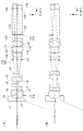
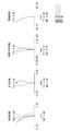
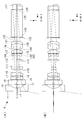
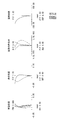
本発明の実施例1に係る内視鏡用対物光学系の構成を図2及び図3に示す。なお、図3において、(A)は通常観察状態を、(B)は近距離観察状態を示し、光線は軸上マージナル光線、最大画角の主光線を示す。また、本実施例に係る内視鏡用対物光学系の通常観察状態の収差曲線図を図4に、近距離観察状態の収差曲線図を図5に示す。
本発明の実施例1に係る内視鏡用対物光学系の構成を図2及び図3に示す。なお、図3において、(A)は通常観察状態を、(B)は近距離観察状態を示し、光線は軸上マージナル光線、最大画角の主光線を示す。また、本実施例に係る内視鏡用対物光学系の通常観察状態の収差曲線図を図4に、近距離観察状態の収差曲線図を図5に示す。
図2に示すように、実施例1に係る内視鏡用対物光学系1において、負の前群G1は、物体側から順に、物体側が平面の平凹レンズの第1レンズL1、赤外カットフィルターCF、両凹レンズの第2レンズL2、両凸レンズの第3レンズL3を備えている。このうち、第2レンズL2と第3レンズL3とは接合された接合レンズCL1となっている。
フォーカシングレンズFは、両凸レンズの第4レンズL4、物体側に凹面を向けた負メニスカスレンズの第5レンズL5を有しており、第4レンズL4と第5レンズL5は接合された接合レンズCL2となっている。フォーカシングレンズFは、正の屈折力を有している。
正の後群G2は、物体側から順に、像側に凹面を向けた負メニスカスレンズの第6レンズL6、像側に凹面を向けた正メニスカスレンズの第7レンズL7、両凸レンズの第8レンズL8、両凸レンズの第9レンズL9、及び物体側に凹面を向けた負メニスカスレンズの第10レンズL10を備えている。このうち、第6レンズL6と第7レンズL7とは接合されて接合レンズCL3となっており、第9レンズL9と第10レンズL10とは接合されて接合レンズCL4となっている。
また、フォーカシングレンズFと後群G2との間に明るさ絞りASが設けられている。
近距離観察時は、フォーカシングレンズFである第4レンズL4と第5レンズL5が光軸上を像側へ移動し、作動距離が短い側にピント合わせを行う。
本発明の実施例1に係る対物光学系のレンズデータを以下に示す。
近距離観察時は、フォーカシングレンズFである第4レンズL4と第5レンズL5が光軸上を像側へ移動し、作動距離が短い側にピント合わせを行う。
本発明の実施例1に係る対物光学系のレンズデータを以下に示す。
レンズデータ
面番号 r d Nd Vd
物体面 ∞ (d0) 1.
1 ∞ 0.6321 1.88300 40.76
2 1.8812 0.6957 1.
3(FS) ∞ 0.0158 1.
4 ∞ 0.9482 1.52100 65.12
5 ∞ 0.3161 1.
6 -5.3755 0.4741 1.88300 40.76
7 3.2188 0.7902 1.58144 40.75
8 -32.1823 (d8) 1.
9 3.9802 1.1062 1.58267 46.42
10 -2.0251 0.6321 1.81600 46.62
11 -54.4755 (d11) 1.
12(AS) ∞ 0.1580 1.
13 11.0632 0.4741 1.88300 40.76
14 1.7988 0.9482 1.80518 25.42
15 6.1860 0.0790 1.
16 2.7854 1.2643 1.58144 40.75
17 -4.4702 0.1264 1.
18 3.3806 1.2643 1.51823 58.90
19 -1.8964 0.4741 1.92286 18.90
20 -20.5234 0.7428 1.
21(FS) ∞ 0.0474 1.
22 ∞ 0.0522 1.53000 56.00
23 ∞ 5.7019 1.72916 54.68
24 ∞ 0.0158 1.51000 64.00
25 ∞ 0.7902 1.61350 50.49
26 ∞ 0.3161 1.
像面 ∞ 0.
面番号 r d Nd Vd
物体面 ∞ (d0) 1.
1 ∞ 0.6321 1.88300 40.76
2 1.8812 0.6957 1.
3(FS) ∞ 0.0158 1.
4 ∞ 0.9482 1.52100 65.12
5 ∞ 0.3161 1.
6 -5.3755 0.4741 1.88300 40.76
7 3.2188 0.7902 1.58144 40.75
8 -32.1823 (d8) 1.
9 3.9802 1.1062 1.58267 46.42
10 -2.0251 0.6321 1.81600 46.62
11 -54.4755 (d11) 1.
12(AS) ∞ 0.1580 1.
13 11.0632 0.4741 1.88300 40.76
14 1.7988 0.9482 1.80518 25.42
15 6.1860 0.0790 1.
16 2.7854 1.2643 1.58144 40.75
17 -4.4702 0.1264 1.
18 3.3806 1.2643 1.51823 58.90
19 -1.8964 0.4741 1.92286 18.90
20 -20.5234 0.7428 1.
21(FS) ∞ 0.0474 1.
22 ∞ 0.0522 1.53000 56.00
23 ∞ 5.7019 1.72916 54.68
24 ∞ 0.0158 1.51000 64.00
25 ∞ 0.7902 1.61350 50.49
26 ∞ 0.3161 1.
像面 ∞ 0.
各種データ 通常観察 近距離観察
d0 20.40000 4.90000
d8 0.48991 1.03205
d11 3.25356 2.71142
d0 20.40000 4.90000
d8 0.48991 1.03205
d11 3.25356 2.71142
(実施例2)
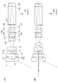
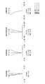
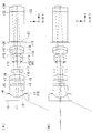
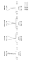
本発明の実施例2に係る内視鏡用対物光学系の構成を図6及び図7に示す。なお、図7において、(A)は通常観察状態を、(B)は近距離観察状態を示し、光線は軸上マージナル光線、最大画角の主光線を示す。また、本実施例に係る内視鏡用対物光学系の通常観察状態の収差曲線図を図8に、近距離観察状態の収差曲線図を図9に示す。
本発明の実施例2に係る内視鏡用対物光学系の構成を図6及び図7に示す。なお、図7において、(A)は通常観察状態を、(B)は近距離観察状態を示し、光線は軸上マージナル光線、最大画角の主光線を示す。また、本実施例に係る内視鏡用対物光学系の通常観察状態の収差曲線図を図8に、近距離観察状態の収差曲線図を図9に示す。
図6に示すように、実施例2に係る内視鏡用対物光学系2において、負の前群G1は、物体側から順に、物体側が平面の平凹レンズの第1レンズL1、赤外カットフィルターCF、両凹レンズの第2レンズL2、両凸レンズの第3レンズL3を備えている。このうち、第2レンズL2と第3レンズL3とは接合された接合レンズCL1となっている。
フォーカシングレンズFは、両凸レンズの第4レンズL4、両凹レンズの第5レンズL5を有しており、第4レンズL4と第5レンズL5は接合された接合レンズCL2となっている。フォーカシングレンズFは、正の屈折力を有している。
正の後群G2は、物体側から順に、像側に凹面を向けた負メニスカスレンズの第6レンズL6、像側に凹面を向けた正メニスカスレンズの第7レンズL7、両凸レンズの第8レンズL8、両凸レンズの第9レンズL9、及び物体側に凹面を向けた負メニスカスレンズの第10レンズL10を備えている。このうち、第6レンズL6と第7レンズL7とは接合されて接合レンズCL3となっており、第9レンズL9と第10レンズL10とは接合されて接合レンズCL4となっている。
また、フォーカシングレンズFと後群G2との間に明るさ絞りASが設けられている。
近距離観察時は、フォーカシングレンズFである第4レンズL4と第5レンズL5が光軸上を像側へ移動し、作動距離が短い側にピント合わせを行う。
本発明の実施例2に係る対物光学系のレンズデータを以下に示す。
近距離観察時は、フォーカシングレンズFである第4レンズL4と第5レンズL5が光軸上を像側へ移動し、作動距離が短い側にピント合わせを行う。
本発明の実施例2に係る対物光学系のレンズデータを以下に示す。
レンズデータ
面番号 r d Nd Vd
物体面 ∞ (d0) 1.
1 ∞ 0.6018 1.88300 40.76
2 1.7838 0.6623 1.
3(FS) ∞ 0.0150 1.
4 ∞ 0.9027 1.52100 65.12
5 ∞ 0.3009 1.
6 -5.8632 0.4514 1.88300 40.76
7 3.0388 0.7523 1.58144 40.75
8 -262.6157 (d8) 1.
9 3.4555 1.0532 1.58267 46.42
10 -1.9593 0.6018 1.81600 46.62
11 188.3682 (d11) 1.
12(AS) ∞ 0.1505 1.
13 6.6902 0.4514 1.88300 40.76
14 1.7629 0.9027 1.80518 25.42
15 4.8177 0.0752 1.
16 2.6152 1.2037 1.58144 40.75
17 -4.6255 0.1204 1.
18 3.3881 1.2037 1.51823 58.90
19 -1.8055 0.4514 1.92286 18.90
20 -14.9878 0.7064 1.
21 ∞ 0.0451 1.
22 ∞ 0.0497 1.53000 56.00
23 ∞ 5.4285 1.72916 54.68
24 ∞ 0.0150 1.51000 64.00
25 ∞ 0.7523 1.61062 50.49
26 ∞ 0.3009 1.
像面 ∞ 0.
面番号 r d Nd Vd
物体面 ∞ (d0) 1.
1 ∞ 0.6018 1.88300 40.76
2 1.7838 0.6623 1.
3(FS) ∞ 0.0150 1.
4 ∞ 0.9027 1.52100 65.12
5 ∞ 0.3009 1.
6 -5.8632 0.4514 1.88300 40.76
7 3.0388 0.7523 1.58144 40.75
8 -262.6157 (d8) 1.
9 3.4555 1.0532 1.58267 46.42
10 -1.9593 0.6018 1.81600 46.62
11 188.3682 (d11) 1.
12(AS) ∞ 0.1505 1.
13 6.6902 0.4514 1.88300 40.76
14 1.7629 0.9027 1.80518 25.42
15 4.8177 0.0752 1.
16 2.6152 1.2037 1.58144 40.75
17 -4.6255 0.1204 1.
18 3.3881 1.2037 1.51823 58.90
19 -1.8055 0.4514 1.92286 18.90
20 -14.9878 0.7064 1.
21 ∞ 0.0451 1.
22 ∞ 0.0497 1.53000 56.00
23 ∞ 5.4285 1.72916 54.68
24 ∞ 0.0150 1.51000 64.00
25 ∞ 0.7523 1.61062 50.49
26 ∞ 0.3009 1.
像面 ∞ 0.
各種データ 通常観察 近距離観察
d0 19.40000 4.70000
d8 0.46642 1.05683
d11 2.91113 2.32071
d0 19.40000 4.70000
d8 0.46642 1.05683
d11 2.91113 2.32071
(実施例3)
本発明の実施例3に係る内視鏡用対物光学系3の構成を図10及び図11に示す。なお、図11において、(A)は通常観察状態を、(B)は近距離観察状態を示し、光線は軸上マージナル光線、最大画角の主光線を示す。また、本実施例に係る内視鏡用対物光学系3の通常観察状態の収差曲線図を図12に、近距離観察状態の収差曲線図を図13に示す。
本発明の実施例3に係る内視鏡用対物光学系3の構成を図10及び図11に示す。なお、図11において、(A)は通常観察状態を、(B)は近距離観察状態を示し、光線は軸上マージナル光線、最大画角の主光線を示す。また、本実施例に係る内視鏡用対物光学系3の通常観察状態の収差曲線図を図12に、近距離観察状態の収差曲線図を図13に示す。
図10に示すように、実施例3に係る内視鏡用対物光学系3において、負の前群G1は、物体側から順に、物体側が平面の平凹レンズの第1レンズL1、赤外カットフィルターCF、両凹レンズの第2レンズL2及び両凸レンズの第3レンズL3を備えている。
フォーカシングレンズFは、物体側に凸面を向けた正メニスカスレンズの第4レンズであり、正の屈折力を有している。
フォーカシングレンズFは、物体側に凸面を向けた正メニスカスレンズの第4レンズであり、正の屈折力を有している。
また、正の後群は、像側に凹面を向けた負メニスカスレンズの第5レンズL5、像側に凹面を向けた正メニスカスレンズの第6レンズL6、両凸レンズの第7レンズL7、両凸レンズの第8レンズL8、及び物体側に凹面を向けた負メニスカスレンズの第9レンズL9を備えている。このうち、第5レンズL5と第6レンズL6は接合されて接合レンズCL5となっており、第8レンズL8と第9レンズL9とは接合されて接合レンズCL6となっている。
また、フォーカシングレンズFと後群G2との間に明るさ絞りASが設けられている。
近距離観察時は、フォーカシングレンズFである第4レンズが光軸上を像側へ移動し、作動距離が短い側にピント合わせを行う。
本発明の実施例3に係る内視鏡用対物光学系3のレンズデータを以下に示す。
近距離観察時は、フォーカシングレンズFである第4レンズが光軸上を像側へ移動し、作動距離が短い側にピント合わせを行う。
本発明の実施例3に係る内視鏡用対物光学系3のレンズデータを以下に示す。
レンズデータ
面番号 r d Nd Vd
物体面 ∞ (d0) 1.
1 ∞ 0.6034 1.88300 40.76
2 1.6946 0.6640 1.
3(FS) ∞ 0.0151 1.
4 ∞ 0.9051 1.52100 65.12
5 ∞ 0.3017 1.
6 -16.6193 0.6034 1.88300 40.76
7 3.5630 1.1341 1.
8 5.9529 0.9049 1.53172 48.84
9 -7.5210 (d9) 1.
10 2.8889 0.7780 1.49700 81.54
11 2.9891 (d11) 1.
12(AS) ∞ 0.1508 1.
13 21.2097 0.4532 1.88300 40.76
14 1.3996 0.8955 1.80518 25.42
15 6.6235 0.1438 1.
16 2.4518 1.0559 1.53172 48.84
17 -3.4187 0.1508 1.
18 3.6407 0.9051 1.58144 40.75
19 -1.7430 0.4572 1.92286 18.90
20 -91.7614 0.6946 1.
21(FS) ∞ 0.0588 1.
22 ∞ 0.0498 1.53000 56.00
23 ∞ 5.4425 1.72916 54.68
24 ∞ 0.0151 1.51000 64.00
25 ∞ 0.7542 1.61062 50.49
26 ∞ 0.3017 1.
像面 ∞ 0.
面番号 r d Nd Vd
物体面 ∞ (d0) 1.
1 ∞ 0.6034 1.88300 40.76
2 1.6946 0.6640 1.
3(FS) ∞ 0.0151 1.
4 ∞ 0.9051 1.52100 65.12
5 ∞ 0.3017 1.
6 -16.6193 0.6034 1.88300 40.76
7 3.5630 1.1341 1.
8 5.9529 0.9049 1.53172 48.84
9 -7.5210 (d9) 1.
10 2.8889 0.7780 1.49700 81.54
11 2.9891 (d11) 1.
12(AS) ∞ 0.1508 1.
13 21.2097 0.4532 1.88300 40.76
14 1.3996 0.8955 1.80518 25.42
15 6.6235 0.1438 1.
16 2.4518 1.0559 1.53172 48.84
17 -3.4187 0.1508 1.
18 3.6407 0.9051 1.58144 40.75
19 -1.7430 0.4572 1.92286 18.90
20 -91.7614 0.6946 1.
21(FS) ∞ 0.0588 1.
22 ∞ 0.0498 1.53000 56.00
23 ∞ 5.4425 1.72916 54.68
24 ∞ 0.0151 1.51000 64.00
25 ∞ 0.7542 1.61062 50.49
26 ∞ 0.3017 1.
像面 ∞ 0.
各種データ 通常観察 近距離観察
d0 19.40000 4.70000
d9 0.34913 2.58407
d11 3.02798 0.79304
d0 19.40000 4.70000
d9 0.34913 2.58407
d11 3.02798 0.79304
(実施例4)
本発明の実施例4に係る内視鏡用対物光学系4の構成を図14及び図15に示す。なお、図15において、(A)は通常観察状態を、(B)は近距離観察状態を示し、光線は軸上マージナル光線、最大画角の主光線を示す。また、本実施例に係る内視鏡用対物光学系4の通常観察状態の収差曲線図を図16に、近距離観察状態の収差曲線図を図17に示す。
本発明の実施例4に係る内視鏡用対物光学系4の構成を図14及び図15に示す。なお、図15において、(A)は通常観察状態を、(B)は近距離観察状態を示し、光線は軸上マージナル光線、最大画角の主光線を示す。また、本実施例に係る内視鏡用対物光学系4の通常観察状態の収差曲線図を図16に、近距離観察状態の収差曲線図を図17に示す。
図14に示すように、実施例4に係る内視鏡用対物光学系4において、負の前群G1は、物体側から順に、物体側が平面の平凹レンズの第1レンズL1、赤外カットフィルターCF、両凹レンズの第2レンズL2及び両凸レンズの第3レンズL3を備えている。
フォーカシングレンズFは、物体側に凹面を向けた負メニスカスレンズの第4レンズであり、負の屈折力を有している。
正の後群G2は、物体側から順に、両凸レンズの第5レンズL5、物体側に凹面を向けた負メニスカスレンズの第6レンズL6、両凸レンズの第7レンズL7、物体側に凹面を向けた負メニスカスレンズの第8レンズL8を備えている。このうち、第5レンズL5と第6レンズL6は接合されて接合レンズCL7となっており、第7レンズL7と第8レンズL8とは接合されて接合レンズCL8となっている。
正の後群G2は、物体側から順に、両凸レンズの第5レンズL5、物体側に凹面を向けた負メニスカスレンズの第6レンズL6、両凸レンズの第7レンズL7、物体側に凹面を向けた負メニスカスレンズの第8レンズL8を備えている。このうち、第5レンズL5と第6レンズL6は接合されて接合レンズCL7となっており、第7レンズL7と第8レンズL8とは接合されて接合レンズCL8となっている。
また、フォーカシングレンズFと後群G2との間に明るさ絞りASが設けられている。
近距離観察時は、フォーカシングレンズFである第4レンズL4が光軸上を物体側へ移動し、作動距離が短い側にピント合わせを行う。
本発明の実施例4に係る内視鏡用対物光学系4のレンズデータを以下に示す。
近距離観察時は、フォーカシングレンズFである第4レンズL4が光軸上を物体側へ移動し、作動距離が短い側にピント合わせを行う。
本発明の実施例4に係る内視鏡用対物光学系4のレンズデータを以下に示す。
レンズデータ
面番号 r d Nd Vd
物体面 ∞ (d0) 1.
1 ∞ 0.5967 1.88300 40.76
2 1.7036 0.7062 1.
3(FS) ∞ 0.0448 1.
4 ∞ 0.8951 1.51800 75.00
5 ∞ 0.2796 1.
6 -4.0284 0.4485 1.88300 40.76
7 8.3388 0.1466 1.
8 3.5894 1.1194 1.92286 18.90
9 -15.8261 (d9) 1.
10 -1.5081 0.7401 1.77529 51.13
11 -2.0343 (d11) 1.
12(AS) ∞ 0.0448 1.
13 7.3029 0.9108 1.50217 57.99
14 -1.8150 0.3729 1.95857 32.95
15 -2.9271 0.0298 1.
16(FS) ∞ 0.0448 1.
17 9.1509 0.9811 1.52890 45.11
18 -1.8128 0.4475 1.92286 18.90
19 -2.8699 0.7099 1.
20(FS) ∞ 0.0448 1.
21 ∞ 0.0492 1.53000 56.00
22 ∞ 5.3823 1.72916 54.68
23 ∞ 0.0149 1.51000 64.00
24 ∞ 0.7459 1.61062 50.49
25 ∞ 0.2984 1.
像面 ∞ 0.
面番号 r d Nd Vd
物体面 ∞ (d0) 1.
1 ∞ 0.5967 1.88300 40.76
2 1.7036 0.7062 1.
3(FS) ∞ 0.0448 1.
4 ∞ 0.8951 1.51800 75.00
5 ∞ 0.2796 1.
6 -4.0284 0.4485 1.88300 40.76
7 8.3388 0.1466 1.
8 3.5894 1.1194 1.92286 18.90
9 -15.8261 (d9) 1.
10 -1.5081 0.7401 1.77529 51.13
11 -2.0343 (d11) 1.
12(AS) ∞ 0.0448 1.
13 7.3029 0.9108 1.50217 57.99
14 -1.8150 0.3729 1.95857 32.95
15 -2.9271 0.0298 1.
16(FS) ∞ 0.0448 1.
17 9.1509 0.9811 1.52890 45.11
18 -1.8128 0.4475 1.92286 18.90
19 -2.8699 0.7099 1.
20(FS) ∞ 0.0448 1.
21 ∞ 0.0492 1.53000 56.00
22 ∞ 5.3823 1.72916 54.68
23 ∞ 0.0149 1.51000 64.00
24 ∞ 0.7459 1.61062 50.49
25 ∞ 0.2984 1.
像面 ∞ 0.
各種データ 通常観察 近距離観察
d0 19.20000 4.60000
d9 1.96471 0.63955
d11 0.28250 1.60767
d0 19.20000 4.60000
d9 1.96471 0.63955
d11 0.28250 1.60767
(実施例5)
本発明の実施例5に係る内視鏡用対物光学系5の構成を図18に示す。なお、本実施例5に係る内視鏡用対物光学系5を構成する各レンズの形状等は実施例4と同一であるのでその説明を省略する。図18において、(A)は通常観察状態を、(B)は近距離観察状態を示し、光線は軸上マージナル光線、最大画角の主光線を示す。また、本実施例に係る内視鏡用対物光学系の通常観察状態の収差曲線図を図19に、近距離観察状態の収差曲線図を図20に示す。
本発明の実施例5に係る対物光学系のレンズデータを以下に示す。
本発明の実施例5に係る内視鏡用対物光学系5の構成を図18に示す。なお、本実施例5に係る内視鏡用対物光学系5を構成する各レンズの形状等は実施例4と同一であるのでその説明を省略する。図18において、(A)は通常観察状態を、(B)は近距離観察状態を示し、光線は軸上マージナル光線、最大画角の主光線を示す。また、本実施例に係る内視鏡用対物光学系の通常観察状態の収差曲線図を図19に、近距離観察状態の収差曲線図を図20に示す。
本発明の実施例5に係る対物光学系のレンズデータを以下に示す。
レンズデータ
面番号 r d Nd Vd
物体面 ∞ (d0) 1.
1 ∞ 0.6019 1.88300 40.76
2 1.7554 0.6970 1.
3(FS) ∞ 0.0451 1.
4 ∞ 0.9029 1.51800 75.00
5 ∞ 0.2599 1.
6 -4.5983 0.4843 1.88300 40.76
7 5.2759 0.1540 1.
8 3.2577 2.1439 1.92286 18.90
9 -45.0144 (d9) 1.
10 -1.3809 0.6003 1.65160 58.55
11 -1.8282 (d11) 1.
12(AS) ∞ 0.0451 1.
13 4.9232 0.9551 1.48749 70.23
14 -1.7032 0.3762 1.88300 40.76
15 -2.5955 0.0301 1.
16(FS) ∞ 0.0451 1.
17 11.1469 0.9767 1.48749 70.23
18 -1.7938 0.4514 2.00330 28.27
19 -2.8063 0.7162 1.
20(FS) ∞ 0.0451 1.
21 ∞ 0.0497 1.53000 56.00
22 ∞ 5.4293 1.72916 54.68
23 ∞ 0.0150 1.51000 64.00
24 ∞ 0.7524 1.61062 50.491
25 ∞ 0.3010 1.
像面 ∞ 0.
面番号 r d Nd Vd
物体面 ∞ (d0) 1.
1 ∞ 0.6019 1.88300 40.76
2 1.7554 0.6970 1.
3(FS) ∞ 0.0451 1.
4 ∞ 0.9029 1.51800 75.00
5 ∞ 0.2599 1.
6 -4.5983 0.4843 1.88300 40.76
7 5.2759 0.1540 1.
8 3.2577 2.1439 1.92286 18.90
9 -45.0144 (d9) 1.
10 -1.3809 0.6003 1.65160 58.55
11 -1.8282 (d11) 1.
12(AS) ∞ 0.0451 1.
13 4.9232 0.9551 1.48749 70.23
14 -1.7032 0.3762 1.88300 40.76
15 -2.5955 0.0301 1.
16(FS) ∞ 0.0451 1.
17 11.1469 0.9767 1.48749 70.23
18 -1.7938 0.4514 2.00330 28.27
19 -2.8063 0.7162 1.
20(FS) ∞ 0.0451 1.
21 ∞ 0.0497 1.53000 56.00
22 ∞ 5.4293 1.72916 54.68
23 ∞ 0.0150 1.51000 64.00
24 ∞ 0.7524 1.61062 50.491
25 ∞ 0.3010 1.
像面 ∞ 0.
各種データ 通常観察 近距離観察
d0 19.40000 4.60000
d9 1.48113 0.63434
d11 0.28799 1.13479
d0 19.40000 4.60000
d9 1.48113 0.63434
d11 0.28799 1.13479
(実施例6)
本発明の実施例6に係る内視鏡用対物光学系6の構成を図21及び図22に示す。なお、図22において、(A)は通常観察状態を、(B)は近距離観察状態を示し、光線は軸上マージナル光線、最大画角の主光線を示す。また、本実施例に係る内視鏡用対物光学系6の通常観察状態の収差曲線図を図23に、近距離観察状態の収差曲線図を図24に示す。
本発明の実施例6に係る内視鏡用対物光学系6の構成を図21及び図22に示す。なお、図22において、(A)は通常観察状態を、(B)は近距離観察状態を示し、光線は軸上マージナル光線、最大画角の主光線を示す。また、本実施例に係る内視鏡用対物光学系6の通常観察状態の収差曲線図を図23に、近距離観察状態の収差曲線図を図24に示す。
図22に示すように、実施例6に係る内視鏡用対物光学系6において、負の前群G1は、物体側から順に、平面の平凹レンズの第1レンズL1、赤外カットフィルターCF、両凹レンズの第2レンズL2、両凸レンズの第3レンズL3を備えている。
フォーカシングレンズFは、物体側に凹面を向けた平凹レンズの第4レンズL4であり、負の屈折力を有している。
フォーカシングレンズFは、物体側に凹面を向けた平凹レンズの第4レンズL4であり、負の屈折力を有している。
正の後群G2は、物体側から順に、像側に凸面を向けた正メニスカスレンズの第5レンズL5、明るさ絞りAS、物体側が平面の平凸レンズの第7レンズL7、両凸レンズの第8レンズL8、及び物体側に凹面を向けた負メニスカスレンズの第9レンズL9を備えている。このうち、第5レンズL5と第6レンズL6は接合されて接合レンズCL9となっており、第8レンズL8と第9レンズL9とは接合されて接合レンズCL10となっている。
また、フォーカシングレンズFと後群G2との間に明るさ絞りASが設けられている。
近距離観察時は、フォーカシングレンズFである第4レンズL4が光軸から退避し、作動距離が短い側にピント合わせを行う。
本発明の実施例6に係る内視鏡用対物光学系6のレンズデータを以下に示す。
近距離観察時は、フォーカシングレンズFである第4レンズL4が光軸から退避し、作動距離が短い側にピント合わせを行う。
本発明の実施例6に係る内視鏡用対物光学系6のレンズデータを以下に示す。
レンズデータ
面番号 r d Nd Vd
物体面 ∞ (d0) 1.
1 ∞ 0.6561 1.88300 40.76
2 1.9220 0.7557 1.
3(FS) ∞ 0.0492 1.
4 ∞ 0.9841 1.51800 75.00
5 ∞ 0.1698 1.
6 -5.6263 0.3856 1.88300 40.76
7 3.3960 0.3075 1.
8 93.7165 0.7666 1.92286 18.90
9 -3.7545 0.7132 1.
10 (r10) 0.4920 (GLA10)
11 (r11) 1.5089 1.
12(FS) ∞ 0.0492 1.
13 -62.7030 0.8784 1.92286 18.90
14 -2.8707 0.4100 2.00330 28.27
15 8.2363 0.0328 1.
16(AS) ∞ 0.0492 1.
17 ∞ 0.7784 1.48749 70.23
18 -2.3726 0.0820 1.
19 3.6087 1.2486 1.48749 70.23
20 -1.8711 0.4920 1.92286 18.90
21 -2.9189 0.7786 1.
22(FS) ∞ 0.0492 1.
23 ∞ 0.0541 1.53000 56.00
24 ∞ 5.9176 1.72916 54.68
25 ∞ 0.0164 1.51000 64.00
26 ∞ 0.8201 1.61062 50.495
27 ∞ 0.3280 1.
像面 ∞ 0.
面番号 r d Nd Vd
物体面 ∞ (d0) 1.
1 ∞ 0.6561 1.88300 40.76
2 1.9220 0.7557 1.
3(FS) ∞ 0.0492 1.
4 ∞ 0.9841 1.51800 75.00
5 ∞ 0.1698 1.
6 -5.6263 0.3856 1.88300 40.76
7 3.3960 0.3075 1.
8 93.7165 0.7666 1.92286 18.90
9 -3.7545 0.7132 1.
10 (r10) 0.4920 (GLA10)
11 (r11) 1.5089 1.
12(FS) ∞ 0.0492 1.
13 -62.7030 0.8784 1.92286 18.90
14 -2.8707 0.4100 2.00330 28.27
15 8.2363 0.0328 1.
16(AS) ∞ 0.0492 1.
17 ∞ 0.7784 1.48749 70.23
18 -2.3726 0.0820 1.
19 3.6087 1.2486 1.48749 70.23
20 -1.8711 0.4920 1.92286 18.90
21 -2.9189 0.7786 1.
22(FS) ∞ 0.0492 1.
23 ∞ 0.0541 1.53000 56.00
24 ∞ 5.9176 1.72916 54.68
25 ∞ 0.0164 1.51000 64.00
26 ∞ 0.8201 1.61062 50.495
27 ∞ 0.3280 1.
像面 ∞ 0.
各種データ 通常観察 近距離観察
d0 21.00000 4.60000
r10 -79.24365 ∞
r11 ∞ ∞
GLA10 1.51633,64.14 空気(Air)
d0 21.00000 4.60000
r10 -79.24365 ∞
r11 ∞ ∞
GLA10 1.51633,64.14 空気(Air)
(実施例7)
本発明の実施例7に係る内視鏡用対物光学系7の構成を図25及び図26に示す。なお、図26において、(A)は通常観察状態を、(B)は近距離観察状態を示し、光線は軸上マージナル光線、最大画角の主光線を示す。また、本実施例に係る内視鏡用対物光学系7の通常観察状態の収差曲線図を図27に、近距離観察状態の収差曲線図を図28に示す。
本発明の実施例7に係る内視鏡用対物光学系7の構成を図25及び図26に示す。なお、図26において、(A)は通常観察状態を、(B)は近距離観察状態を示し、光線は軸上マージナル光線、最大画角の主光線を示す。また、本実施例に係る内視鏡用対物光学系7の通常観察状態の収差曲線図を図27に、近距離観察状態の収差曲線図を図28に示す。
図25に示すように、実施例7に係る内視鏡用対物光学系7において、負の前群G1は、物体側から順に、物体側が平面の平凹レンズの第1レンズL1、赤外カットフィルターCF、両凹レンズの第2レンズL2、像側に凸面を向けた正メニスカスレンズの第3レンズL3を備えている。
フォーカシングレンズFは、物体側に凹面を向けた負メニスカスレンズの第4レンズであり、負の屈折力を有している。
正の後群G2は、像側に凸面を向けた正メニスカスレンズの第5レンズL5、物体側に凹面を向けた負メニスカスレンズの第6レンズL6、両凸レンズの第7レンズL7、及び物体側に凹面を向けた負メニスカスレンズの第8レンズL8を備えている。このうち、第5レンズL5と第6レンズL6とは接合されて接合レンズCL9となっており、第7レンズL7と第8レンズL8とは接合されて接合レンズCL10となっている。
正の後群G2は、像側に凸面を向けた正メニスカスレンズの第5レンズL5、物体側に凹面を向けた負メニスカスレンズの第6レンズL6、両凸レンズの第7レンズL7、及び物体側に凹面を向けた負メニスカスレンズの第8レンズL8を備えている。このうち、第5レンズL5と第6レンズL6とは接合されて接合レンズCL9となっており、第7レンズL7と第8レンズL8とは接合されて接合レンズCL10となっている。
また、フォーカシングレンズFと後群G2との間に明るさ絞りASが設けられている。
近距離観察時は、フォーカシングレンズである第4レンズが光軸から退避し、作動距離が短い側にピント合わせを行う。
本発明の実施例7に係る内視鏡用対物光学系7のレンズデータを以下に示す。
近距離観察時は、フォーカシングレンズである第4レンズが光軸から退避し、作動距離が短い側にピント合わせを行う。
本発明の実施例7に係る内視鏡用対物光学系7のレンズデータを以下に示す。
レンズデータ
面番号 r d Nd Vd
物体面 ∞ (d0) 1.
1 ∞ 0.6131 1.88300 40.76
2 1.7879 0.6897 1.
3(FS) ∞ 0.5749 1.
4 ∞ 0.9196 1.51800 75.00
5 ∞ 0.3832 1.
6 -6.8635 0.4598 1.88300
7 3.5076 0.3832 1.
8 -35.3125 0.7510 1.92286
9 -3.0759 0.5044 1.
10 (r10) 0.4598 (GLA10)
11 (r11) 1.4035 1.
12(AS) ∞ 0.1533 1.
13 -10.8850 0.9043 1.53172 48.84
14 -1.7164 0.3832 2.00330 28.27
15 -2.2765 0.0766 1.
16 5.5291 0.9196 1.48749 70.23
17 -2.1547 0.4598 1.92286 18.90
18 -3.7217 0.7231 1.
19(FS) ∞ 0.0460 1.
20 ∞ 0.0506 1.53000 56.00
21 ∞ 5.5298 1.72916 54.68
22 ∞ 0.0153 1.51000 64.00
23 ∞ 0.7663 1.61062 50.49
24 ∞ 0.3065 1.
像面 ∞ 0.
面番号 r d Nd Vd
物体面 ∞ (d0) 1.
1 ∞ 0.6131 1.88300 40.76
2 1.7879 0.6897 1.
3(FS) ∞ 0.5749 1.
4 ∞ 0.9196 1.51800 75.00
5 ∞ 0.3832 1.
6 -6.8635 0.4598 1.88300
7 3.5076 0.3832 1.
8 -35.3125 0.7510 1.92286
9 -3.0759 0.5044 1.
10 (r10) 0.4598 (GLA10)
11 (r11) 1.4035 1.
12(AS) ∞ 0.1533 1.
13 -10.8850 0.9043 1.53172 48.84
14 -1.7164 0.3832 2.00330 28.27
15 -2.2765 0.0766 1.
16 5.5291 0.9196 1.48749 70.23
17 -2.1547 0.4598 1.92286 18.90
18 -3.7217 0.7231 1.
19(FS) ∞ 0.0460 1.
20 ∞ 0.0506 1.53000 56.00
21 ∞ 5.5298 1.72916 54.68
22 ∞ 0.0153 1.51000 64.00
23 ∞ 0.7663 1.61062 50.49
24 ∞ 0.3065 1.
像面 ∞ 0.
各種データ 通常観察 近距離観察
d0 19.20000 5.30000
r10 -8.11519 ∞
r11 -9.67274 ∞
GLA10 1.51633,64.14 空気(Air)
d0 19.20000 5.30000
r10 -8.11519 ∞
r11 -9.67274 ∞
GLA10 1.51633,64.14 空気(Air)
(実施例8)
本発明の実施例8に係る内視鏡用対物光学系8の構成を図29及び図30に示す。なお、図30において、(A)は通常観察状態を、(B)は近距離観察状態を示し、光線は軸上マージナル光線、最大画角の主光線を示す。また、本実施例に係る内視鏡用対物光学系の通常観察状態の収差曲線図を図31に、近距離観察状態の収差曲線図を図32に示す。
本発明の実施例8に係る内視鏡用対物光学系8の構成を図29及び図30に示す。なお、図30において、(A)は通常観察状態を、(B)は近距離観察状態を示し、光線は軸上マージナル光線、最大画角の主光線を示す。また、本実施例に係る内視鏡用対物光学系の通常観察状態の収差曲線図を図31に、近距離観察状態の収差曲線図を図32に示す。
図29に示すように、実施例8に係る内視鏡用対物光学系8において、負の前群G1は、物体側から順に、物体側が平面の平凹レンズの第1レンズL1、両凹レンズの第2レンズL2、物体側が平面の平凸レンズの第3レンズL3を備えている。
フォーカシングレンズFは、物体側に凹面を向けた負メニスカスレンズの第4レンズL4であり、負の屈折力を有している。
フォーカシングレンズFは、物体側に凹面を向けた負メニスカスレンズの第4レンズL4であり、負の屈折力を有している。
正の後群2は、物体側が平面の平凸レンズの第5レンズL5、像側が平面の平凹レンズの第6レンズL6、明るさ絞りAS、物体側が平面の平凸レンズの第7レンズL7、両凸レンズの第8レンズL8、及び、物体側に凹面を向けた負メニスカスレンズの第9レンズL9を備えている。このうち、第5レンズL5と第6レンズL6とは接合されて接合レンズCL11となっており、第8レンズL8と第9レンズL9は接合されて接合レンズCL12となっている。
フォーカシングレンズFと後群G2との間には、赤外カットフィルターCFが配置されている。
近距離観察時は、フォーカシングレンズである第4レンズが光軸から退避し、作動距離が短い側にピント合わせを行う。
本発明の実施例8に係る内視鏡用対物光学系8のレンズデータを以下に示す。
近距離観察時は、フォーカシングレンズである第4レンズが光軸から退避し、作動距離が短い側にピント合わせを行う。
本発明の実施例8に係る内視鏡用対物光学系8のレンズデータを以下に示す。
レンズデータ
面番号 r d Nd Vd
物体面 ∞ (d0) 1.
1 ∞ 0.6110 1.88300 40.76
2 1.7735 0.7027 1.
3(FS) ∞ 0.8554 1.
4 -4.9355 0.5652 1.88300 40.76
5 6.8999 0.1375 1.
6(FS) ∞ 0.2139 1.
7 ∞ 0.6568 1.92286 18.90
8 -4.3352 0.2291 1.
9 (r9) 1.2220 (GLA9)
10 (r10) 0.1375 1.
11 ∞ 0.9165 1.51800 75.00
12 ∞ 0.0458 1.
13(FS) ∞ 0.9013 1.
14(FS) ∞ 0.0458 1.
15 ∞ 1.1915 1.69895 30.13
16 -1.6925 0.3819 1.88300 40.76
17 ∞ 0.0458 1.
18(AS) ∞ 0. 1.
19 ∞ 0.9318 1.48749 70.23
20 -2.5754 0.0153 1.
21(FS) ∞ 0.0611 1.
22 5.2685 1.0540 1.48749 70.23
23 -1.8987 0.4583 1.92286 18.90
24 -2.9955 0.8821 1.
25(FS) ∞ 0.0458 1.
26 ∞ 0.0504 1.53000 56.00
27 ∞ 1.5489 1.72916 54.68
28 ∞ 0.0215 1.51000 64.00
29 ∞ 3.8647 1.72916 54.68
30 ∞ 1.2474 1.
像面 ∞ 0.
面番号 r d Nd Vd
物体面 ∞ (d0) 1.
1 ∞ 0.6110 1.88300 40.76
2 1.7735 0.7027 1.
3(FS) ∞ 0.8554 1.
4 -4.9355 0.5652 1.88300 40.76
5 6.8999 0.1375 1.
6(FS) ∞ 0.2139 1.
7 ∞ 0.6568 1.92286 18.90
8 -4.3352 0.2291 1.
9 (r9) 1.2220 (GLA9)
10 (r10) 0.1375 1.
11 ∞ 0.9165 1.51800 75.00
12 ∞ 0.0458 1.
13(FS) ∞ 0.9013 1.
14(FS) ∞ 0.0458 1.
15 ∞ 1.1915 1.69895 30.13
16 -1.6925 0.3819 1.88300 40.76
17 ∞ 0.0458 1.
18(AS) ∞ 0. 1.
19 ∞ 0.9318 1.48749 70.23
20 -2.5754 0.0153 1.
21(FS) ∞ 0.0611 1.
22 5.2685 1.0540 1.48749 70.23
23 -1.8987 0.4583 1.92286 18.90
24 -2.9955 0.8821 1.
25(FS) ∞ 0.0458 1.
26 ∞ 0.0504 1.53000 56.00
27 ∞ 1.5489 1.72916 54.68
28 ∞ 0.0215 1.51000 64.00
29 ∞ 3.8647 1.72916 54.68
30 ∞ 1.2474 1.
像面 ∞ 0.
各種データ 通常観察 近距離観察
d0 19.70000 4.80000
r9 -7.28027 ∞
r10 -9.26913 ∞
GLA9 1.88300,40.76 空気(Air)
d0 19.70000 4.80000
r9 -7.28027 ∞
r10 -9.26913 ∞
GLA9 1.88300,40.76 空気(Air)
なお、上記した実施例1~実施例8の構成における上記条件式(1)~(4)の数値を表1~表3に示す。


〔第2の実施形態〕
次に、本発明の第2の実施形態について説明する。
上述した各実施例に係る内視鏡用対物光学系は撮像装置に適用することができ、以下、上記した何れかの内視鏡用対物光学系(以下、単に「対物光学系」という)を適用した撮像装置の例について説明する。
次に、本発明の第2の実施形態について説明する。
上述した各実施例に係る内視鏡用対物光学系は撮像装置に適用することができ、以下、上記した何れかの内視鏡用対物光学系(以下、単に「対物光学系」という)を適用した撮像装置の例について説明する。
図33は、本発明の第2の実施形態にかかる撮像装置10の概略構成を示し、(A)は全体構成を模式的に示す図、(B)は撮像素子の第1及び第2の領域に夫々結像する画像における被写体の向きを示す図である。
図34は、図33の撮像装置10における対物光学系と分割素子と第2反射部材の斜視図である。図35は図33の撮像装置10における画像選択部の構成例を示す説明図で、(A)はその一例を示し、(B)は他の例を示している。
図34は、図33の撮像装置10における対物光学系と分割素子と第2反射部材の斜視図である。図35は図33の撮像装置10における画像選択部の構成例を示す説明図で、(A)はその一例を示し、(B)は他の例を示している。
撮像装置10は、上記した対物光学系11と、偏光解消板12と、撮像素子13と、偏光ビームスプリッタ14と、波長板15と、第1反射部材16と、第2反射部材17と、画像処理部18を有している。図33中、19は画像表示装置である。
対物光学系11は、物体からの光束を結像させる機能を有し、像側がテレセントリックに構成されている。偏光解消板12は、対物光学系11と偏光ビームスプリッタ14との間に配置されている。撮像素子13は、ローリングシャッタ方式のCMOSセンサで構成され、対物光学系11の結像位置近傍に配置されている。
偏光ビームスプリッタ14は、対物光学系11と撮像素子13との間の光路上であって撮像素子13における第1領域13aの上方に配置され、偏光ビームスプリッタ面14aで対物光学系11からの光束を反射光束と透過光束の2つの光束に分割する。なお、ここでは、偏光ビームスプリッタ14は、S偏光成分の直線偏光を反射し、P偏光成分の直線偏光を透過するものとする。
波長板15は、λ/4板からなり、光軸を中心に回転可能に構成されている。第1反射部材16は、ミラーで構成されており、偏光ビームスプリッタ面14aで反射し、波長板15を透過した光束を折り返して反射させる。
第2反射部材17は、プリズムで構成されており、全反射面17aで偏光ビームスプリッタ14を透過した光を反射させる。なお、プリズム17は、全反射面17aにミラーコートを施して反射面を構成してもよい。
そして、本実施形態に係る撮像装置10は、波長板15及び偏光ビームスプリッタ14を介して第1反射部材16で反射した光束を撮像素子13における第1領域13aに結像させ、他方、第2反射部材17で反射した光束を撮像素子13における第1領域13aとは異なる第2領域13bに結像させる。
画像処理部18は、撮像素子13に接続し、図示省略した中央処理演算装置に設けられ、第1画像処理部18aと、第2画像処理部18bと、第3画像処理部18cと、第4画像処理部18dと、第5画像処理部18eを有している。
第1画像処理部18aは、第1領域13aの画像と第2領域13bの画像の向き(回転)を補正するように構成されている。
第1画像処理部18aは、第1領域13aの画像と第2領域13bの画像の向き(回転)を補正するように構成されている。
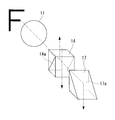
第1領域13a、第2領域13bに結像する画像の向きは、例えば、図34に示すような”F”の文字を観察する場合、夫々図33(B)に示すような向きになる。即ち、第1領域13aに結像する画像は、第1領域13aの中心点を中心として時計回りに90度回転するとともに、第1領域13aの中心点を通る図33(B)における縦方向の軸を中心として180度回転した向きとなっている。また、第2領域13bに結像する画像は、第2領域13bの中心点を中心として時計回りに90度回転した向きとなっている。
そこで、第1領域13a、第2領域13bの夫々に結像する画像を画像表示装置19に表示させる場合には、第1画像処理部18aを介して、第1領域13a、第2領域13bの夫々に結像する画像を夫々の領域の中心点を中心として反時計回りに90度回転させ、更に第1領域13aの画像に対しては第1領域13aの中心点を通る図33(B)における縦方向の軸を中心として180度回転させて鏡像を補正する。
第3画像処理部18cは、第1領域13aの画像と第2領域13bの画像の夫々のホワイトバランスを調整可能に構成されている。
第4画像処理部18dは、第1領域13aの画像と第2領域13bの画像の夫々の中心位置の移動(選択)可能に構成されている。
第5画像処理部18eは、第1領域13aの画像と第2領域13bの画像の夫々の表示範囲(倍率)を調整可能に構成されている。
第4画像処理部18dは、第1領域13aの画像と第2領域13bの画像の夫々の中心位置の移動(選択)可能に構成されている。
第5画像処理部18eは、第1領域13aの画像と第2領域13bの画像の夫々の表示範囲(倍率)を調整可能に構成されている。
第2画像処理部18bは、本発明の画像選択部に相当し、第1領域13aの画像と第2領域13bの画像とを比較し、焦点が合った領域の画像を表示用画像として選択するように構成されている。
詳しくは、第2画像処理部18bは、例えば、図35(A)に示すように、夫々の領域13a,13bに接続する高域通過フィルタ18b1a,18b1bと、高域通過フィルタ18b1a,18b1bに接続する比較器18b2と、比較器18b2及び夫々の領域13a,13bに接続する切替器18b3を有し、第1領域13a,第2領域13bの画像を、高域通過フィルタ18b1a,18b1bで高域成分を抽出し、抽出した高域成分を比較器18b2で比較し、高域成分の多い領域の画像を切替器18b3で選択するように構成される。
また、例えば、図35(B)に示すように、一方の領域13aのみに接続するデフォーカスフィルタ18b4と、デフォーカスフィルタ18b4に接続するとともに他方の領域13bに接続する比較器18b2と、一方の領域13a及び比較器18b2に接続する切替器18b3を有し、デフォーカスフィルタ18b4によりデフォーカスされた一方の領域13aの画像信号とでフォーカスされていない他方の領域13bの画像信号を比較器18b2で比較し、一致した部分は他の領域13bの画像、一致しない部分は領域13aの画像、を切替器18b3で選択するように構成してもよい。
画像表示装置19は、第2画像処理部18bが選択した画像を表示する表示領域を有している。なお、画像表示装置19は、第1及び第2の領域13a,13bの夫々に結像する画像を表示する表示領域を有していてもよい。
画像表示装置19は、第2画像処理部18bが選択した画像を表示する表示領域を有している。なお、画像表示装置19は、第1及び第2の領域13a,13bの夫々に結像する画像を表示する表示領域を有していてもよい。
このように構成された撮像装置10によれば、対物光学系11からの光束は、偏光解消板12を通り、偏光方向の偏りが解消された状態で、偏光ビームスプリッタ14に入射する。偏光ビームスプリッタ14に入射した光は、偏光ビームスプリッタ面14aで直線偏光のS偏光成分とP偏光成分とに分離される。
偏光ビームスプリッタ面14aで反射したS偏光成分の直線偏光の光束は、λ/4板15を通り偏光状態が円偏光に変換され、ミラー16で反射する。ミラー16で反射した光束は、再びλ/4板15を通り、偏光状態が円偏光からP偏光成分の直線偏光に変換され、再び偏光ビームスプリッタ14に入射し、偏光ビームスプリッタ面14aを透過して、撮像素子13の第1領域13aに結像する。
また、対物光学系11、偏光解消板12を経て、偏光ビームスプリッタ14に入射したときに偏光ビームスプリッタ面14aを透過したS偏光成分の直線偏光の光束は、プリズム17の全反射面17aで反射され、撮像素子13の第2領域13bに結像する。
撮像素子13は、上述したようにローリングシャッタ方式で構成されており、図33(B)に矢印で示す方向に1ラインずつ画像を読み出す。第2画像処理部18bは、1ラインずつ読み出された、第1領域13a、第2領域13bの夫々に結像する画像を比較し、焦点が合った画像を表示用画像として選択する。
なお、第2画像処理部18bが選択した1ラインずつの画像は、合成されて画像表示装置19に表示される。
なお、第2画像処理部18bが選択した1ラインずつの画像は、合成されて画像表示装置19に表示される。
1~8 内視鏡用対物光学系
10 撮像装置
11 対物光学系
12 偏光解消板
13 撮像素子
14 偏光ビームスプリッタ
15 波長板
16 第1反射部材
17 第2反射部材
18 画像処理部
19 画像表示装置
G1 前群
G2 後群
L1 第1レンズ
L2 第2レンズ
L3 第3レンズ
L4 第4レンズ
L5 第5レンズ
L6 第6レンズ
L7 第7レンズ
L8 第8レンズ
L9 第9レンズ
L10 第10レンズ
CL1~CL12 接合レンズ
AS 明るさ絞り
FS フレア絞り
P 光学プリズム
CG カバーガラス
10 撮像装置
11 対物光学系
12 偏光解消板
13 撮像素子
14 偏光ビームスプリッタ
15 波長板
16 第1反射部材
17 第2反射部材
18 画像処理部
19 画像表示装置
G1 前群
G2 後群
L1 第1レンズ
L2 第2レンズ
L3 第3レンズ
L4 第4レンズ
L5 第5レンズ
L6 第6レンズ
L7 第7レンズ
L8 第8レンズ
L9 第9レンズ
L10 第10レンズ
CL1~CL12 接合レンズ
AS 明るさ絞り
FS フレア絞り
P 光学プリズム
CG カバーガラス
Claims (5)
- 物体側から像側へ順に、負の屈折力を有する前群、フォーカシングレンズ、正の屈折力を有する後群を備え、
前記前群及び前記後群が、光軸上に常に固定されており、以下の条件式(1)及び(2)を満たす内視鏡用対物光学系。
4<FB/FL …(1)
FL/|fc|<0.1 …(2)
ただし、FBは、内視鏡用対物光学系全系のバックフォーカスであり、後群の最も像側のレンズ面から全系の後ろ側焦点位置までの距離である。また、FLは、内視鏡用対物光学系全系の焦点距離であり、fcはフォーカシングレンズの焦点距離であり、|fc|はその絶対値である。 - 以下の条件式(3)及び(4)を満たす請求項1に記載の内視鏡用対物光学系。
-3<F_F/FL<-0.9 …(3)
2.5<F_R/FL<5 …(4)
ただし、F_Fは前群の焦点距離であり、F_Rは後群の焦点距離である。 - 前記フォーカシングレンズが、正の屈折率を有し、
作動距離が長い側から短い側に向かって変化するとき、前記フォーカシングレンズを像側に移動することで作動距離が短い側にピント合わせる請求項1又は請求項2に記載の内視鏡用対物光学系。 - 前記フォーカシングレンズが、負の屈折率を有し、
作動距離が長い側から短い側に向かって変化するとき、前記フォーカシングレンズを物体側に移動することで作動距離が短い側にピント合わせる請求項1又は請求項2に記載の内視鏡用対物光学系。 - 請求項1乃至請求項4の何れかに記載の内視鏡用対物光学系と、
該内視鏡用対物光学系の結像位置近傍に配置された1つの撮像素子と、
前記対物レンズと前記撮像素子との間に配置され、前記対物レンズからの光束を反射光束と透過光束の2つの光束に分割するための分割素子と、
前記反射光束を折り返して反射させるための第1反射部材と、
前記透過光束を反射させるための第2反射部材と、を有し、
前記分割素子を介して前記第1反射部材で反射した光束を前記撮像素子における第1領域に結像させ、
前記第2反射部材で反射した光束を前記撮像素子における前記第1領域とは異なる第2領域に結像させる撮像装置。
Priority Applications (4)
| Application Number | Priority Date | Filing Date | Title |
|---|---|---|---|
| CN201380021538.4A CN104246573B (zh) | 2013-02-22 | 2013-12-26 | 内窥镜用物镜光学系统及摄像装置 |
| EP13875918.8A EP2960701A4 (en) | 2013-02-22 | 2013-12-26 | OPTICAL ENDOSCOPE OBJECTIVE SYSTEM AND IMAGING DEVICE |
| JP2014529739A JP5607278B1 (ja) | 2013-02-22 | 2013-12-26 | 内視鏡用対物光学系及び撮像装置 |
| US14/309,539 US9459443B2 (en) | 2013-02-22 | 2014-06-19 | Endoscopic objective optical system and imaging apparatus |
Applications Claiming Priority (2)
| Application Number | Priority Date | Filing Date | Title |
|---|---|---|---|
| JP2013-033440 | 2013-02-22 | ||
| JP2013033440 | 2013-02-22 |
Related Child Applications (1)
| Application Number | Title | Priority Date | Filing Date |
|---|---|---|---|
| US14/309,539 Continuation US9459443B2 (en) | 2013-02-22 | 2014-06-19 | Endoscopic objective optical system and imaging apparatus |
Publications (1)
| Publication Number | Publication Date |
|---|---|
| WO2014129089A1 true WO2014129089A1 (ja) | 2014-08-28 |
Family
ID=51390900
Family Applications (1)
| Application Number | Title | Priority Date | Filing Date |
|---|---|---|---|
| PCT/JP2013/085015 Ceased WO2014129089A1 (ja) | 2013-02-22 | 2013-12-26 | 内視鏡用対物光学系及び撮像装置 |
Country Status (5)
| Country | Link |
|---|---|
| US (1) | US9459443B2 (ja) |
| EP (1) | EP2960701A4 (ja) |
| JP (1) | JP5607278B1 (ja) |
| CN (1) | CN104246573B (ja) |
| WO (1) | WO2014129089A1 (ja) |
Cited By (16)
| Publication number | Priority date | Publication date | Assignee | Title |
|---|---|---|---|---|
| WO2016047421A1 (ja) * | 2014-09-22 | 2016-03-31 | オリンパス株式会社 | 内視鏡対物光学系 |
| WO2017043352A1 (ja) * | 2015-09-07 | 2017-03-16 | Hoya株式会社 | 内視鏡用変倍光学系、及び内視鏡 |
| WO2017073292A1 (ja) * | 2015-10-29 | 2017-05-04 | オリンパス株式会社 | 内視鏡撮像ユニット |
| WO2017145265A1 (ja) * | 2016-02-23 | 2017-08-31 | Hoya株式会社 | 内視鏡用変倍光学系及び内視鏡 |
| WO2017179387A1 (ja) * | 2016-04-13 | 2017-10-19 | オリンパス株式会社 | 対物光学系 |
| WO2018123847A1 (ja) * | 2016-12-26 | 2018-07-05 | オリンパス株式会社 | 内視鏡システム |
| WO2019167310A1 (ja) * | 2018-02-27 | 2019-09-06 | オリンパス株式会社 | 内視鏡用対物光学系 |
| WO2019198362A1 (ja) * | 2018-04-11 | 2019-10-17 | オリンパス株式会社 | 内視鏡対物光学系 |
| WO2019207699A1 (ja) * | 2018-04-26 | 2019-10-31 | オリンパス株式会社 | 対物光学系及びそれを用いた撮像装置 |
| WO2020178883A1 (ja) * | 2019-03-01 | 2020-09-10 | オリンパス株式会社 | 広角光学系及びそれを備えた撮像装置 |
| JPWO2019198348A1 (ja) * | 2018-04-11 | 2021-03-25 | オリンパス株式会社 | 立体内視鏡対物光学系及びそれを備えた内視鏡 |
| WO2021065319A1 (ja) * | 2019-09-30 | 2021-04-08 | 株式会社ニコン | 光学系、光学機器及び光学系の製造方法 |
| CN114839759A (zh) * | 2022-04-08 | 2022-08-02 | 长春理工大学 | 一种带有视向棱镜的显微内窥镜物镜系统 |
| US12066603B2 (en) | 2019-03-01 | 2024-08-20 | Olympus Corporation | Wide-angle optical system including three lens units of −++ refractive powers, and image pickup apparatus using the same |
| US12085707B2 (en) | 2019-03-01 | 2024-09-10 | Olympus Corporation | Wide-angle optical system and image pickup apparatus using the same |
| US12117602B2 (en) | 2019-03-01 | 2024-10-15 | Olympus Corporation | Wide-angle optical system and image pickup apparatus using the same |
Families Citing this family (14)
| Publication number | Priority date | Publication date | Assignee | Title |
|---|---|---|---|---|
| WO2016067838A1 (ja) | 2014-10-30 | 2016-05-06 | オリンパス株式会社 | 内視鏡用対物光学系 |
| CN106461929B (zh) * | 2015-02-17 | 2019-03-05 | 奥林巴斯株式会社 | 内窥镜系统 |
| US10394004B2 (en) * | 2016-04-05 | 2019-08-27 | Qualcomm Incorporated | Systems and devices having single-sided wafer-level optics |
| KR102620545B1 (ko) | 2016-04-06 | 2024-01-03 | 삼성전기주식회사 | 촬상 광학계 |
| WO2018173412A1 (ja) * | 2017-03-24 | 2018-09-27 | オリンパス株式会社 | 内視鏡システム |
| DE102017113273A1 (de) * | 2017-06-16 | 2018-12-20 | avateramedical GmBH | Objektiv für ein Endoskop und Endoskop |
| CN107728298B (zh) * | 2017-11-20 | 2019-03-08 | 嘉兴中润光学科技有限公司 | 焦距放大增倍镜头 |
| JP6899030B2 (ja) | 2018-03-22 | 2021-07-07 | オリンパス株式会社 | 対物光学系、撮像装置、内視鏡、及び内視鏡システム |
| JP6995978B2 (ja) | 2018-03-27 | 2022-01-17 | オリンパス株式会社 | 内視鏡用対物光学系、撮像装置、内視鏡及び内視鏡システム |
| TWI806947B (zh) * | 2018-12-21 | 2023-07-01 | 佳能企業股份有限公司 | 光學鏡頭 |
| CN111367054B (zh) * | 2020-04-21 | 2025-01-21 | 厦门力鼎光电股份有限公司 | 一种小型高清的光学成像镜头 |
| WO2023047458A1 (ja) * | 2021-09-21 | 2023-03-30 | オリンパス株式会社 | 対物光学系、撮像ユニット、内視鏡及び内視鏡装置 |
| CN119867620B (zh) * | 2025-03-10 | 2026-02-03 | 浙江之科立上医疗科技有限公司 | 一种内窥镜3d变焦镜头及内窥成像系统 |
| CN120128798B (zh) * | 2025-05-12 | 2025-08-15 | 新光维医疗科技(苏州)股份有限公司 | 基于景深分析的狭小空间成像自动对焦方法及系统 |
Citations (7)
| Publication number | Priority date | Publication date | Assignee | Title |
|---|---|---|---|---|
| JP2000089105A (ja) * | 1998-09-11 | 2000-03-31 | Olympus Optical Co Ltd | 対物光学系 |
| JP2008107391A (ja) * | 2006-10-23 | 2008-05-08 | Olympus Medical Systems Corp | 内視鏡対物光学系 |
| JP2008224842A (ja) * | 2007-03-09 | 2008-09-25 | Olympus Corp | 対物光学系 |
| WO2011070930A1 (ja) * | 2009-12-11 | 2011-06-16 | オリンパスメディカルシステムズ株式会社 | 対物光学系 |
| JP4819969B2 (ja) | 2009-04-16 | 2011-11-24 | オリンパスメディカルシステムズ株式会社 | 対物光学系 |
| JP4919419B2 (ja) | 2007-04-09 | 2012-04-18 | 富士フイルム株式会社 | 内視鏡用対物レンズおよび内視鏡 |
| WO2013027459A1 (ja) * | 2011-08-24 | 2013-02-28 | オリンパスメディカルシステムズ株式会社 | 撮像装置及び撮像装置システム |
Family Cites Families (6)
| Publication number | Priority date | Publication date | Assignee | Title |
|---|---|---|---|---|
| JP3944050B2 (ja) * | 2001-11-05 | 2007-07-11 | オリンパス株式会社 | 手術用顕微鏡 |
| JP4197886B2 (ja) * | 2002-04-19 | 2008-12-17 | オリンパス株式会社 | 電子撮像装置 |
| JP4684613B2 (ja) * | 2004-10-14 | 2011-05-18 | キヤノン株式会社 | 光学機器 |
| JP4823641B2 (ja) * | 2005-10-19 | 2011-11-24 | 富士フイルム株式会社 | 投写レンズおよびこれを用いた投写型表示装置 |
| JP4653823B2 (ja) * | 2008-06-06 | 2011-03-16 | オリンパスメディカルシステムズ株式会社 | 対物光学系 |
| WO2011070897A1 (ja) * | 2009-12-07 | 2011-06-16 | オリンパスメディカルシステムズ株式会社 | 対物レンズおよび内視鏡装置 |
-
2013
- 2013-12-26 WO PCT/JP2013/085015 patent/WO2014129089A1/ja not_active Ceased
- 2013-12-26 EP EP13875918.8A patent/EP2960701A4/en not_active Withdrawn
- 2013-12-26 CN CN201380021538.4A patent/CN104246573B/zh active Active
- 2013-12-26 JP JP2014529739A patent/JP5607278B1/ja active Active
-
2014
- 2014-06-19 US US14/309,539 patent/US9459443B2/en active Active
Patent Citations (8)
| Publication number | Priority date | Publication date | Assignee | Title |
|---|---|---|---|---|
| JP2000089105A (ja) * | 1998-09-11 | 2000-03-31 | Olympus Optical Co Ltd | 対物光学系 |
| JP2008107391A (ja) * | 2006-10-23 | 2008-05-08 | Olympus Medical Systems Corp | 内視鏡対物光学系 |
| JP2008224842A (ja) * | 2007-03-09 | 2008-09-25 | Olympus Corp | 対物光学系 |
| JP4675348B2 (ja) | 2007-03-09 | 2011-04-20 | オリンパスメディカルシステムズ株式会社 | 対物光学系 |
| JP4919419B2 (ja) | 2007-04-09 | 2012-04-18 | 富士フイルム株式会社 | 内視鏡用対物レンズおよび内視鏡 |
| JP4819969B2 (ja) | 2009-04-16 | 2011-11-24 | オリンパスメディカルシステムズ株式会社 | 対物光学系 |
| WO2011070930A1 (ja) * | 2009-12-11 | 2011-06-16 | オリンパスメディカルシステムズ株式会社 | 対物光学系 |
| WO2013027459A1 (ja) * | 2011-08-24 | 2013-02-28 | オリンパスメディカルシステムズ株式会社 | 撮像装置及び撮像装置システム |
Non-Patent Citations (1)
| Title |
|---|
| See also references of EP2960701A4 * |
Cited By (38)
| Publication number | Priority date | Publication date | Assignee | Title |
|---|---|---|---|---|
| JPWO2016047421A1 (ja) * | 2014-09-22 | 2017-04-27 | オリンパス株式会社 | 内視鏡対物光学系 |
| WO2016047421A1 (ja) * | 2014-09-22 | 2016-03-31 | オリンパス株式会社 | 内視鏡対物光学系 |
| US9817226B2 (en) | 2014-09-22 | 2017-11-14 | Olympus Corporation | Endoscope objective optical system |
| WO2017043352A1 (ja) * | 2015-09-07 | 2017-03-16 | Hoya株式会社 | 内視鏡用変倍光学系、及び内視鏡 |
| US10036883B2 (en) | 2015-09-07 | 2018-07-31 | Hoya Corporation | Endoscope magnification optical system and endoscope |
| JPWO2017043352A1 (ja) * | 2015-09-07 | 2018-06-21 | Hoya株式会社 | 内視鏡用変倍光学系、及び内視鏡 |
| JPWO2017073292A1 (ja) * | 2015-10-29 | 2018-01-11 | オリンパス株式会社 | 内視鏡撮像ユニット |
| WO2017073292A1 (ja) * | 2015-10-29 | 2017-05-04 | オリンパス株式会社 | 内視鏡撮像ユニット |
| WO2017146021A1 (ja) * | 2016-02-23 | 2017-08-31 | Hoya株式会社 | 内視鏡用変倍光学系、内視鏡及び内視鏡システム |
| JPWO2017146021A1 (ja) * | 2016-02-23 | 2018-12-13 | Hoya株式会社 | 内視鏡用変倍光学系、内視鏡及び内視鏡システム |
| WO2017145265A1 (ja) * | 2016-02-23 | 2017-08-31 | Hoya株式会社 | 内視鏡用変倍光学系及び内視鏡 |
| US10898061B2 (en) | 2016-02-23 | 2021-01-26 | Hoya Corporation | Endoscope magnification optical system, endoscope, and endoscope system |
| JPWO2017179387A1 (ja) * | 2016-04-13 | 2018-04-19 | オリンパス株式会社 | 対物光学系 |
| WO2017179387A1 (ja) * | 2016-04-13 | 2017-10-19 | オリンパス株式会社 | 対物光学系 |
| US10842360B2 (en) | 2016-04-13 | 2020-11-24 | Olympus Corporation | Objective optical system |
| WO2018123847A1 (ja) * | 2016-12-26 | 2018-07-05 | オリンパス株式会社 | 内視鏡システム |
| JP6363818B1 (ja) * | 2016-12-26 | 2018-07-25 | オリンパス株式会社 | 内視鏡システム |
| JPWO2019167310A1 (ja) * | 2018-02-27 | 2020-12-03 | オリンパス株式会社 | 対物光学系、及び内視鏡 |
| WO2019167310A1 (ja) * | 2018-02-27 | 2019-09-06 | オリンパス株式会社 | 内視鏡用対物光学系 |
| US11460676B2 (en) | 2018-02-27 | 2022-10-04 | Olympus Corporation | Objective optical system and endoscope |
| JP7047075B2 (ja) | 2018-04-11 | 2022-04-04 | オリンパス株式会社 | 内視鏡対物光学系、撮像装置及び内視鏡 |
| WO2019198362A1 (ja) * | 2018-04-11 | 2019-10-17 | オリンパス株式会社 | 内視鏡対物光学系 |
| JPWO2019198362A1 (ja) * | 2018-04-11 | 2021-02-25 | オリンパス株式会社 | 内視鏡対物光学系、撮像装置及び内視鏡 |
| JPWO2019198348A1 (ja) * | 2018-04-11 | 2021-03-25 | オリンパス株式会社 | 立体内視鏡対物光学系及びそれを備えた内視鏡 |
| JP7095076B2 (ja) | 2018-04-11 | 2022-07-04 | オリンパス株式会社 | 立体内視鏡対物光学系及びそれを備えた内視鏡 |
| WO2019207699A1 (ja) * | 2018-04-26 | 2019-10-31 | オリンパス株式会社 | 対物光学系及びそれを用いた撮像装置 |
| US12117602B2 (en) | 2019-03-01 | 2024-10-15 | Olympus Corporation | Wide-angle optical system and image pickup apparatus using the same |
| WO2020178883A1 (ja) * | 2019-03-01 | 2020-09-10 | オリンパス株式会社 | 広角光学系及びそれを備えた撮像装置 |
| JPWO2020178883A1 (ja) * | 2019-03-01 | 2021-09-30 | オリンパス株式会社 | 広角光学系及びそれを備えた撮像装置 |
| US12085707B2 (en) | 2019-03-01 | 2024-09-10 | Olympus Corporation | Wide-angle optical system and image pickup apparatus using the same |
| US12066603B2 (en) | 2019-03-01 | 2024-08-20 | Olympus Corporation | Wide-angle optical system including three lens units of −++ refractive powers, and image pickup apparatus using the same |
| JPWO2021065319A1 (ja) * | 2019-09-30 | 2021-04-08 | ||
| JP7288617B2 (ja) | 2019-09-30 | 2023-06-08 | 株式会社ニコン | 光学系及び光学機器 |
| CN114424105A (zh) * | 2019-09-30 | 2022-04-29 | 株式会社尼康 | 光学系统、光学设备及光学系统的制造方法 |
| WO2021065319A1 (ja) * | 2019-09-30 | 2021-04-08 | 株式会社ニコン | 光学系、光学機器及び光学系の製造方法 |
| CN114424105B (zh) * | 2019-09-30 | 2025-01-17 | 株式会社尼康 | 光学系统及光学设备 |
| CN114839759B (zh) * | 2022-04-08 | 2023-11-07 | 长春理工大学 | 一种带有视向棱镜的显微内窥镜物镜系统 |
| CN114839759A (zh) * | 2022-04-08 | 2022-08-02 | 长春理工大学 | 一种带有视向棱镜的显微内窥镜物镜系统 |
Also Published As
| Publication number | Publication date |
|---|---|
| EP2960701A1 (en) | 2015-12-30 |
| JPWO2014129089A1 (ja) | 2017-02-02 |
| US20150042773A1 (en) | 2015-02-12 |
| JP5607278B1 (ja) | 2014-10-15 |
| US9459443B2 (en) | 2016-10-04 |
| CN104246573B (zh) | 2016-10-12 |
| CN104246573A (zh) | 2014-12-24 |
| EP2960701A4 (en) | 2016-09-21 |
Similar Documents
| Publication | Publication Date | Title |
|---|---|---|
| JP5607278B1 (ja) | 内視鏡用対物光学系及び撮像装置 | |
| JP6253437B2 (ja) | 結像光学系及びそれを有する画像投射装置 | |
| JP6197147B1 (ja) | 対物光学系 | |
| WO2011049195A1 (ja) | 立体撮影用対物光学系および内視鏡 | |
| JP2006184844A (ja) | 結像光学系及びこれを用いた撮像装置 | |
| CN106461929A (zh) | 内窥镜系统 | |
| JP5712751B2 (ja) | 光学系、この光学系を有する撮像装置、及び、光学系の製造方法 | |
| WO2018047335A1 (ja) | 立体視内視鏡 | |
| JP2018155833A (ja) | 撮像レンズおよび撮像装置 | |
| JP2013242594A (ja) | 投射光学系及び投射型画像表示装置 | |
| WO2019171642A1 (ja) | 内視鏡光学系及び内視鏡装置 | |
| JP5379154B2 (ja) | デュアル焦点距離レンズ系 | |
| JPWO2017183371A1 (ja) | 内視鏡システム | |
| JPWO2017073292A1 (ja) | 内視鏡撮像ユニット | |
| JP2017209154A (ja) | 内視鏡システム | |
| JP2012133175A (ja) | 撮像光学系および撮像装置 | |
| JP2010014897A (ja) | レンズ系及び光学装置 | |
| JP6836466B2 (ja) | 内視鏡対物光学系 | |
| JP6296803B2 (ja) | 光学系及びそれを有する撮像装置 | |
| JP4884318B2 (ja) | 焦点検出光学系及びそれを用いた撮像装置 | |
| JP4744908B2 (ja) | 結像レンズ | |
| JP4792896B2 (ja) | 縮小光学系及びこれを搭載する光学機器 | |
| JP6363818B1 (ja) | 内視鏡システム | |
| JP2004361725A (ja) | ソリッド型カタディオプトリック光学系 | |
| JP2008008981A (ja) | ファインダー光学系とこれを有する光学機器 |
Legal Events
| Date | Code | Title | Description |
|---|---|---|---|
| ENP | Entry into the national phase |
Ref document number: 2014529739 Country of ref document: JP Kind code of ref document: A |
|
| WWE | Wipo information: entry into national phase |
Ref document number: 2013875918 Country of ref document: EP |
|
| 121 | Ep: the epo has been informed by wipo that ep was designated in this application |
Ref document number: 13875918 Country of ref document: EP Kind code of ref document: A1 |
|
| NENP | Non-entry into the national phase |
Ref country code: DE |