WO2014129315A1 - 内燃機関の制御装置 - Google Patents
内燃機関の制御装置 Download PDFInfo
- Publication number
- WO2014129315A1 WO2014129315A1 PCT/JP2014/052821 JP2014052821W WO2014129315A1 WO 2014129315 A1 WO2014129315 A1 WO 2014129315A1 JP 2014052821 W JP2014052821 W JP 2014052821W WO 2014129315 A1 WO2014129315 A1 WO 2014129315A1
- Authority
- WO
- WIPO (PCT)
- Prior art keywords
- voltage
- boost
- internal combustion
- combustion engine
- valve opening
- Prior art date
- Legal status (The legal status is an assumption and is not a legal conclusion. Google has not performed a legal analysis and makes no representation as to the accuracy of the status listed.)
- Ceased
Links
Images


Classifications
-
- F—MECHANICAL ENGINEERING; LIGHTING; HEATING; WEAPONS; BLASTING
- F02—COMBUSTION ENGINES; HOT-GAS OR COMBUSTION-PRODUCT ENGINE PLANTS
- F02D—CONTROLLING COMBUSTION ENGINES
- F02D41/00—Electrical control of supply of combustible mixture or its constituents
- F02D41/20—Output circuits, e.g. for controlling currents in command coils
-
- F—MECHANICAL ENGINEERING; LIGHTING; HEATING; WEAPONS; BLASTING
- F02—COMBUSTION ENGINES; HOT-GAS OR COMBUSTION-PRODUCT ENGINE PLANTS
- F02D—CONTROLLING COMBUSTION ENGINES
- F02D41/00—Electrical control of supply of combustible mixture or its constituents
- F02D41/22—Safety or indicating devices for abnormal conditions
- F02D41/221—Safety or indicating devices for abnormal conditions relating to the failure of actuators or electrically driven elements
-
- F—MECHANICAL ENGINEERING; LIGHTING; HEATING; WEAPONS; BLASTING
- F02—COMBUSTION ENGINES; HOT-GAS OR COMBUSTION-PRODUCT ENGINE PLANTS
- F02D—CONTROLLING COMBUSTION ENGINES
- F02D41/00—Electrical control of supply of combustible mixture or its constituents
- F02D41/24—Electrical control of supply of combustible mixture or its constituents characterised by the use of digital means
- F02D41/26—Electrical control of supply of combustible mixture or its constituents characterised by the use of digital means using computer, e.g. microprocessor
-
- F—MECHANICAL ENGINEERING; LIGHTING; HEATING; WEAPONS; BLASTING
- F02—COMBUSTION ENGINES; HOT-GAS OR COMBUSTION-PRODUCT ENGINE PLANTS
- F02D—CONTROLLING COMBUSTION ENGINES
- F02D41/00—Electrical control of supply of combustible mixture or its constituents
- F02D41/30—Controlling fuel injection
-
- F—MECHANICAL ENGINEERING; LIGHTING; HEATING; WEAPONS; BLASTING
- F02—COMBUSTION ENGINES; HOT-GAS OR COMBUSTION-PRODUCT ENGINE PLANTS
- F02D—CONTROLLING COMBUSTION ENGINES
- F02D41/00—Electrical control of supply of combustible mixture or its constituents
- F02D41/20—Output circuits, e.g. for controlling currents in command coils
- F02D2041/2003—Output circuits, e.g. for controlling currents in command coils using means for creating a boost voltage, i.e. generation or use of a voltage higher than the battery voltage, e.g. to speed up injector opening
-
- F—MECHANICAL ENGINEERING; LIGHTING; HEATING; WEAPONS; BLASTING
- F02—COMBUSTION ENGINES; HOT-GAS OR COMBUSTION-PRODUCT ENGINE PLANTS
- F02D—CONTROLLING COMBUSTION ENGINES
- F02D41/00—Electrical control of supply of combustible mixture or its constituents
- F02D41/20—Output circuits, e.g. for controlling currents in command coils
- F02D2041/202—Output circuits, e.g. for controlling currents in command coils characterised by the control of the circuit
- F02D2041/2051—Output circuits, e.g. for controlling currents in command coils characterised by the control of the circuit using voltage control
-
- F—MECHANICAL ENGINEERING; LIGHTING; HEATING; WEAPONS; BLASTING
- F02—COMBUSTION ENGINES; HOT-GAS OR COMBUSTION-PRODUCT ENGINE PLANTS
- F02D—CONTROLLING COMBUSTION ENGINES
- F02D41/00—Electrical control of supply of combustible mixture or its constituents
- F02D41/30—Controlling fuel injection
- F02D41/38—Controlling fuel injection of the high pressure type
- F02D41/40—Controlling fuel injection of the high pressure type with means for controlling injection timing or duration
- F02D41/402—Multiple injections
Definitions
- the present invention relates to a control device for an internal combustion engine that controls a fuel injection valve that directly injects fuel into a combustion chamber.
- Patent Document 1 discloses multi-stage injection control in which fuel injection is performed a plurality of times during one cycle of the internal combustion engine. According to this control, the amount of fuel adhering in the combustion chamber can be reduced and the uniformity of the air-fuel mixture can be increased, and the exhaust performance can be improved.
- multi-stage injection has a problem that heat generation of the control unit (ECU) increases.
- ECU control unit
- a cylinder injection type internal combustion engine in order to open the fuel injection valve against a high fuel pressure, it is known to boost the battery voltage and use the boosted voltage (valve opening voltage).
- the generation means generates heat during pressure increase.
- the pressure boosting opportunity also increases, and heat is further generated.
- the temperature in the ECU incorporating the valve opening voltage generating means rises excessively, and electronic components in the ECU may malfunction or break down.
- Patent Document 2 discloses a technique of cooling the electronic control device with a blower fan when the temperature in the ECU rises excessively.
- JP 2011-132898 A Japanese Patent No. 4319710
- the present invention has been made in view of such a problem, and provides a control device that prevents a temperature increase in the ECU without using a new cooling device such as a blower fan by suppressing heat generation of the ECU. It is in.
- the booster circuit that boosts the battery voltage to generate the boosted voltage, and drives the fuel injection valve by applying the battery voltage and the boosted voltage to the coil.
- a control apparatus for a direct injection internal combustion engine comprising a drive circuit, comprising: a boost voltage adjusting unit that adjusts a target boost voltage of the boost circuit based on an operating state of the vehicle.
- the target value of the valve opening voltage is adjusted by the measured value or estimated value of the control device temperature, thereby suppressing the heat generation of the ECU and without using a new cooling device such as a blower fan. Temperature rise can be prevented.
- FIG. 1 is a system configuration diagram of an internal combustion engine. It is a circuit block diagram of a fuel-injection apparatus. It is a figure which shows the flowchart of fuel-injection control. It is a block diagram of fuel injection control. It is a figure which shows correction
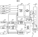
- FIG. 1 shows an internal combustion engine system configuration diagram of the present invention. This figure shows a cross-sectional view of the internal combustion engine 11.
- the amount of intake air is adjusted by the throttle valve 2.
- An intake amount of the intake air is measured by an air flow meter 1, and a signal thereof is transmitted to an ECU (Engine Control Unit) 7.
- the intake air passes through the intake valve 17 and enters the combustion chamber 12 of the internal combustion engine, and forms an air-fuel mixture with the fuel injected from the fuel injection valve 3.
- the fuel injection valve 3 is open / close controlled by a signal from the ECU 7.
- the mixture of fuel and intake air formed in the combustion chamber 12 is ignited by a spark ignition device 9.
- the spark ignition device 9 is controlled to be ignited by a signal from the ECU 7.
- the ignited air-fuel mixture burns and expands to push down the piston 13.
- the output shaft (crankshaft) is connected to the piston 13 and rotates when the piston 13 is pushed down to output energy.
- the crankshaft is provided with a crank angle signal plate 5 and a crank angle sensor 6 for detecting the rotational angular velocity (engine speed) and the angular position of the crankshaft, and a signal from the crank angle sensor 6 is transmitted to the ECU 7. .
- the fuel pressure sensor 4 is a sensor for measuring the pressure in the fuel supply passage 14 to the fuel injection valve 3.
- the water temperature sensor 8 is a sensor that is attached to the cooling water passage of the internal combustion engine 11 and measures the cooling water temperature of the engine.
- the ECU temperature sensor 19 is a sensor that is attached inside the ECU 7 and measures the temperature inside the ECU.
- the intake air temperature sensor 20 is a sensor for measuring the intake air temperature (outside air temperature).
- FIG. 2 shows a circuit configuration diagram of the fuel injection device.
- the ECU 7 receives power supply from the battery 52.
- the ECU 7 includes a CPU 104, a fuel injection valve driving unit 115, and a valve opening voltage generating unit 116.
- the CPU 104 controls the entire internal combustion engine including fuel injection control.
- the fuel injection valve driving unit 115 applies the valve opening voltage generated by the valve opening voltage generation unit 116 or the battery voltage 52 to the fuel injection valve 3 to inject fuel.
- the valve opening voltage is a voltage for opening the fuel injection valve 3. Since the valve opening voltage opens the valve body against high fuel pressure, a voltage higher than the battery voltage is required. Therefore, the valve opening voltage generator 116 is necessary.
- the valve opening voltage generation unit 116 includes three components: a valve opening voltage target value adjustment unit 114, a valve opening voltage detection unit (comparator) 109, and a valve opening voltage booster 54.
- the valve opening voltage target value calculated by the CPU 104 is sent to the valve opening voltage selection switch drive driver 108 of the valve opening voltage target value adjustment unit 114.
- the valve opening voltage target value output from the CPU 104 by the valve opening voltage target value adjustment unit 114 is set as a threshold value for determining whether or not the valve opening voltage boosting unit 54 has a boosting operation.
- valve opening voltage detector (comparator) 109 the valve opening voltage target value is compared with the actual valve opening voltage value.
- the valve opening voltage booster 54 boosts the valve opening voltage and approaches the valve opening voltage target value.
- the valve opening voltage actual value is higher than the valve opening voltage target value, boosting by the valve opening voltage booster 54 is not performed, and the valve opening voltage actual value is lower than the valve opening voltage target value due to fuel injection of the fuel injection valve 3. Do nothing until.
- the case where there was one valve opening voltage target value was shown here, it is not restricted to this.
- the boost voltage target value can be selected from three types of 40V, 60V, and 80V as an example.
- Sw5 switching element for boost voltage 40V
- Sw6 switching element for boost voltage 60V
- Sw7 switching element for boosted voltage 80V
- the ratio between the boost voltage 40V resistor 110 and the voltage divider resistor 113 is set to be 16: 1 in advance, and the voltage upstream of the voltage divider resistor 113 is exactly 2.5V when the boost voltage is 40V. .
- the ratio between the 60V resistor 111 and the voltage dividing resistor 113 is preset as 24: 1
- the ratio between the 80V resistor 112 and the voltage dividing resistor 113 is preset as 32: 1.
- the valve opening voltage of the high-voltage capacitor 100 is not directly input to the valve opening voltage detector (comparator) 109 so that the input rating of the valve opening voltage detector (comparator) 109 is satisfied.
- the divided voltage value is input as the actual valve opening voltage value, the present invention is not limited to this.
- the divided voltage value is compared with the reference voltage of 2.5 V by the valve opening voltage detection unit 109, and the comparison result is sent to the valve opening voltage boosting unit 54. Based on the comparison result, the valve opening voltage boosting unit 54 starts or stops the valve opening voltage boosting operation.
- the means for changing the voltage dividing ratio of the boosted voltage is not limited to switching of a plurality of voltage dividing resistors, and for example, the voltage dividing ratio may be changed by changing the resistance value of the variable resistor. Further, the valve opening voltage target value may be adjusted by fixing the voltage dividing ratio and changing the reference voltage for comparison with the divided voltage.
- valve opening voltage booster 54 Inside the valve opening voltage booster 54, a high-voltage capacitor 100, a booster element 101, and Sw4 (a boosting switching element) are provided.
- the boost control means 102 When the boost control means 102 is turned on, and the valve opening voltage detector 109 detects that the valve opening voltage is insufficient below the target value, the SW4 is repeatedly turned on and off at a high speed, and the predetermined voltage is set. Boost the pressure so that
- valve opening voltage is increased and replenished sequentially when the voltage drops below the target value due to fuel injection.
- the target value may include an upper limit target value and a lower limit target value so that the valve opening voltage is adjusted to a predetermined range.
- the boost operation by the valve opening voltage booster 54 is stopped, and when the valve opening voltage decreases to the lower limit target value, the boost operation by the valve opening voltage booster 54 can be started.
- the valve opening voltage can be adjusted to be within a predetermined range.
- the target value to be adjusted by the valve opening voltage target value adjusting unit 114 it is possible to adjust the valve opening voltage actually generated by adjusting at least one of the upper limit target value and the lower limit target value.
- the fluctuation range of the valve opening voltage can be further reduced by adjusting both target values.
- the boost stop condition of the valve opening voltage booster 54 may be that the valve opening voltage reaches the upper limit target value, and the boost start condition may be performed in synchronization with the fuel injection start timing. Also in this case, since the upper limit target value is adjusted by the valve opening voltage target value adjustment unit 114, the same effect can be obtained.
- step 200 a fuel injection amount is calculated (block 506).
- the fuel injection amount is calculated based on the intake air amount 502, the engine speed 503, and the water temperature 504.
- step 201 the number of multistage injections is calculated (block 507).
- the number of multistage injections is calculated based on the intake air amount 502, the engine speed 503, and the water temperature 504.
- the number of multi-stage injections indicates how many times the fuel is injected in each cylinder per cycle. In the operating region on the low rotation and low load side, the gas flow of the air-fuel mixture in the combustion chamber of the internal combustion engine is weak, so the number of multistage injections is large. Also, in order to promote early activation of the catalyst at low water temperatures, the multistage injection is increased to ensure combustion stability.
- a valve opening voltage target value is calculated (block 505).
- the valve opening voltage is a voltage applied to the fuel injection valve when the fuel injection valve is opened.
- the valve opening voltage booster generates heat, the ECU internal temperature rises excessively, and the electronic components in the ECU may malfunction or fail. . Therefore, a temperature sensor is provided in the ECU, and when the ECU temperature 500 is high, it is determined that the valve opening voltage generation unit is generating heat, and the valve opening voltage target value is reduced.
- the ECU temperature can be estimated even when there is no ECU temperature sensor.
- the temperature around the ECU can be estimated from the outside air temperature 511, the vehicle speed 510, and the water temperature 504. If the number of fuel injections per unit time obtained from the multistage injection number 507 is taken into consideration, the ECU temperature can be estimated with higher accuracy.
- the valve opening voltage target value may be controlled on the condition that the estimated value or measured value of the ECU temperature has risen to a predetermined value or more, but is not limited thereto.
- the valve opening voltage target value may be controlled on the condition that the ECU temperature is predicted to rise. As described above, the valve opening voltage target value is controlled by the actual ECU temperature or the estimated ECU temperature.
- the target value of the valve opening voltage is increased in accordance with the increase in the fuel pressure to facilitate the valve opening, and the deterioration of the exhaust / fuel consumption performance is prevented.
- step 203 the valve opening voltage target value is compared with the previous value in (S202) to determine whether or not there is a change.
- step 204 when the valve opening voltage target value is changed in (S204), the valve opening voltage target value is adjusted (block 114).
- step 205 the fuel injection valve energization time 508 is calculated.
- the fuel injection valve energization time 508 is calculated based on the fuel injection amount 506, the fuel pressure 501, the multistage injection frequency 507, and the valve opening voltage (block 508).
- the present invention is characterized in that the fuel injection valve energization time is corrected according to the level of the valve opening voltage.
- FIG. 5 shows a case where the fuel injection valve is energized. After energization is turned ON, the fuel injection valve is opened by applying a valve opening voltage. Thereafter, the battery voltage is applied and the valve opening is maintained. After the application pulse is turned off, the fuel injection valve is closed by the spring force of the fuel injection valve and the fuel pressure.
- the valve body of the fuel injection valve opens slowly when the valve opening voltage is small (dashed line portion) and when the valve opening voltage is large (solid line portion). Therefore, the amount of fuel injection is reduced by the area of the shaded area (300 in the figure). Therefore, when the same fuel amount is injected regardless of the valve opening voltage, the application pulse time is corrected from the point 302 in the figure to the point 303 so that the hatched area (300 in the figure) and the dotted line part The areas (301 in the figure) are made equal to equalize the fuel injection amount. In this way, the fuel injection consideration is corrected by correcting the energization time of the fuel injection valve.
- step 206 the fuel injection start timing 509 is calculated (block 509).
- the fuel injection start timing 509 is calculated based on the intake air amount 502, the engine speed 503, the water temperature 504, and the multistage injection frequency 507. Here, assuming that the number of multistage injections is 3, three fuel injection start timings 509 are calculated.
- Step 207 indicates the start of the process of repeatedly injecting fuel for the number of multistage injections. Here, when the fuel has been injected by the number of multistage injections, the process is terminated.
- step 208 a self-diagnosis of the valve opening voltage (block 512) is performed. Diagnosis is made using equation (1).
- Target valve opening voltage target value-valve opening voltage actual value > Predetermined value That is, the absolute value of the difference between the valve opening voltage target value calculated by the valve opening voltage target value calculation unit (block 505) and the actual valve opening voltage value If the value is larger than the predetermined value, self-diagnosis is abnormal.
- step 209 it is checked whether it is the fuel injection start time. In the case of Yes, fuel injection is performed.
- step 210 it is checked whether the valve opening voltage is smaller than the valve opening voltage target value and the self-diagnosis is normal. In the case of Yes, in step 211 (S211), the valve opening voltage booster (block 54) boosts the voltage. In the case of No, the process returns to before (S209).
- step 212 it is determined whether the diagnosis is normal or abnormal in the diagnosis of (S208).
- the fuel injection is performed by the fuel injection valve drive driver (block 107) in steps 213 (S213) and 214 (S214). That is, the valve opening voltage and the battery voltage are applied to the fuel injection valve, and fuel injection is performed.
- step 213 (S213) is not performed and only step 214 (S214) is performed. That is, only the battery voltage is applied without applying the valve opening voltage. This is performed in order to prevent the fuel injection valve from failing due to the failure of the valve opening voltage booster (block 54). Further, when only the battery voltage is applied, the valve opening time is greatly extended, so that the fuel injection valve energization time is also extended.
- step 215 the process returns to the beginning of the repetition process (S207).
- a device such as a cooling fan is not required, and the heat generation of the control device can be suppressed.
- the target valve opening voltage of the fuel injection valve is lowered to generate heat while maintaining the number of injections. Can be suppressed.
- the control device generates heat, the number of multi-stage injections can be maintained, so that the exhaust performance is improved.
- the valve opening voltage when the temperature of the control device is detected, estimated by the outside air temperature, the vehicle speed, the coolant temperature, the number of fuel injections per unit time, and the estimated temperature is high, the valve opening voltage By determining that the heat generation of the generating means has increased and lowering the target value of the valve opening voltage, the opportunity for high voltage generation of the valve opening voltage generating means can be reduced and the heat generation can be suppressed.
- the fuel injection valve becomes difficult to open, and exhaust / fuel consumption performance deteriorates. Therefore, the target value of the valve opening voltage is increased. This makes it easier to open the valve and prevents the exhaust and fuel consumption performance from deteriorating.
- an error in the fuel injection amount caused by adjusting the valve opening voltage can be absorbed by correction. That is, when the valve opening voltage is low, it takes more time to open the fuel injection valve than when the valve opening voltage is high, so that the pulse width can be corrected to be longer.
- an abnormality of the valve opening voltage generating means or the valve opening voltage detecting means is detected from these differences.
- the valve-opening voltage generating means fails, the fuel injection valve may also fail. Therefore, the failure of the fuel injection valve can be prevented beforehand by detecting the abnormality and performing fail-safe.
Landscapes
- Engineering & Computer Science (AREA)
- Chemical & Material Sciences (AREA)
- Combustion & Propulsion (AREA)
- Mechanical Engineering (AREA)
- General Engineering & Computer Science (AREA)
- Computer Hardware Design (AREA)
- Microelectronics & Electronic Packaging (AREA)
- Electrical Control Of Air Or Fuel Supplied To Internal-Combustion Engine (AREA)
- Combined Controls Of Internal Combustion Engines (AREA)
Abstract
Description
| 目標開弁電圧目標値 - 開弁電圧実際値 | > 所定値
即ち、開弁電圧目標値算出部(ブロック505)にて算出された開弁電圧目標値と開弁電圧実際値の差分の絶対値が所定値より大きい場合、自己診断異常とする。
Claims (12)
- バッテリ電圧を昇圧して昇圧電圧を生成する昇圧回路と、前記バッテリ電圧と前記昇圧電圧とをコイルへ印加することで燃料噴射弁を駆動する駆動回路と、を備える筒内噴射式内燃機関の制御装置において、
車両の運転状態に基づいて前記昇圧回路の目標昇圧電圧を調整する昇圧電圧調整部を備えることを特徴とした筒内噴射式内燃機関の制御装置。 - 前記制御装置の温度を測定または推定する温度取得手段を備え、
前記昇圧電圧調整部は、前記温度取得手段が測定または推定した温度に基づき、前記昇圧回路の目標昇圧電圧を調整することを特徴とする請求項1に記載の筒内噴射式内燃機関の制御装置。 - 前記駆動回路は前記筒内噴射式内燃機関の一行程中に複数回燃料を分割噴射するように前記燃料噴射弁を駆動し、前記昇圧電圧調整部は前記分割噴射の回数に基づき、前記昇圧回路の目標昇圧電圧を調整することを特徴とする請求項1に記載の筒内噴射式内燃機関の制御装置。
- 請求項1にて、前記燃料噴射弁に供給する燃料の圧力を検出する燃料圧力検出手段を備え、前記燃料圧力検出手段の検出結果に基づき前記昇圧回路の目標昇圧電圧を調整することを特徴とする請求項1に記載の筒内噴射式内燃機関の制御装置。
- 外気温と車両速度と前記筒内噴射式内燃機関の冷却水温度とを検出する手段を備え、前記昇圧電圧調整部は、前記外気温、前記車両速度、前記冷却水温度のうち少なくとも1つを用いて、前記昇圧回路の目標昇圧電圧を調整することを特徴とする請求項3記載の筒内噴射式内燃機関の制御装置。
- 前記昇圧電圧調整部は、前記昇圧電圧を分圧するための分圧抵抗と、前記分圧抵抗による分圧比を切り替える分圧比切り替え回路と、分圧された前記昇圧電圧と予め設定した基準電圧とを比較する比較回路と、を備え、前記昇圧回路は前記比較回路の比較結果に基づき昇圧動作を行うことを特徴とする請求項1に記載の筒内噴射式内燃機関の制御装置。
- 前記分圧比切り替え回路は、複数の分圧抵抗の切り替え、または分圧抵抗の抵抗値を可変することにより、分圧比を切り替えることを特徴とする請求項6に記載の筒内噴射式内燃機関の制御装置。
- 前記昇圧電圧調整部は、前記昇圧電圧と予め設定した基準電圧とを比較する比較回路と、前記基準電圧を可変する基準電圧可変手段と、を備え、前記昇圧回路は前記比較回路の比較結果に基づき昇圧動作を行うことを特徴とする請求項1に記載の筒内噴射式内燃機関の制御装置。
- 前記燃料噴射弁に通電する電流波形を、前記目標昇圧電圧に基づき可変することを特徴とする請求項1に記載の筒内噴射式内燃機関の制御装置。
- 前記目標昇圧電圧と前記昇圧電圧の差分の絶対値が所定値を超えた場合、前記昇圧回路または前記昇圧電圧を検出する手段のいずれかが異常と判定する異常判定手段を供えることを特徴とする請求項1に記載の筒内噴射式内燃機関の制御装置。
- 前記異常判定手段により異常と判定された場合、前記昇圧回路の停止または前記燃料噴射弁への前記バッテリ電圧のみの駆動を行うことを特徴とする請求項9記載の筒内噴射式内燃機関の制御装置。
- 前記目標昇圧電圧は、前記昇圧回路の昇圧停止を判定するための上限目標値と前記昇圧回路の昇圧開始を判定するための下限目標値とを含み、前記昇圧電圧調整部は前記上限目標値と前記下限目標値とのうち少なくとも一つを調整することを特徴とする請求項1に記載の筒内噴射式内燃機関の制御装置。
Priority Applications (3)
| Application Number | Priority Date | Filing Date | Title |
|---|---|---|---|
| CN201480009425.7A CN105074179A (zh) | 2013-02-20 | 2014-02-07 | 内燃机的控制装置 |
| US14/768,709 US20160003182A1 (en) | 2013-02-20 | 2014-02-07 | Control Device for Internal Combustion Engine |
| EP14754697.2A EP2960474A4 (en) | 2013-02-20 | 2014-02-07 | CONTROL DEVICE FOR A COMBUSTION ENGINE |
Applications Claiming Priority (2)
| Application Number | Priority Date | Filing Date | Title |
|---|---|---|---|
| JP2013030544A JP2014159772A (ja) | 2013-02-20 | 2013-02-20 | 内燃機関の制御装置 |
| JP2013-030544 | 2013-02-20 |
Publications (1)
| Publication Number | Publication Date |
|---|---|
| WO2014129315A1 true WO2014129315A1 (ja) | 2014-08-28 |
Family
ID=51391111
Family Applications (1)
| Application Number | Title | Priority Date | Filing Date |
|---|---|---|---|
| PCT/JP2014/052821 Ceased WO2014129315A1 (ja) | 2013-02-20 | 2014-02-07 | 内燃機関の制御装置 |
Country Status (5)
| Country | Link |
|---|---|
| US (1) | US20160003182A1 (ja) |
| EP (1) | EP2960474A4 (ja) |
| JP (1) | JP2014159772A (ja) |
| CN (1) | CN105074179A (ja) |
| WO (1) | WO2014129315A1 (ja) |
Families Citing this family (6)
| Publication number | Priority date | Publication date | Assignee | Title |
|---|---|---|---|---|
| US10309336B2 (en) * | 2015-02-09 | 2019-06-04 | Hitachi Automotive Systems, Ltd. | Control device for fuel injection valve |
| JP6475116B2 (ja) * | 2015-07-21 | 2019-02-27 | 株式会社Subaru | 燃料噴射制御装置 |
| EP3339615B1 (en) | 2015-08-21 | 2020-11-25 | Hitachi Automotive Systems, Ltd. | Booster device for driving injector |
| JP6562011B2 (ja) * | 2017-02-14 | 2019-08-21 | トヨタ自動車株式会社 | 燃料噴射制御装置 |
| JP7367614B2 (ja) * | 2020-05-28 | 2023-10-24 | 株式会社デンソー | 噴射制御装置 |
| JP7354940B2 (ja) * | 2020-06-29 | 2023-10-03 | 株式会社デンソー | 噴射制御装置 |
Citations (8)
| Publication number | Priority date | Publication date | Assignee | Title |
|---|---|---|---|---|
| JP2008172966A (ja) * | 2007-01-15 | 2008-07-24 | Toyota Motor Corp | 負荷駆動回路の制御装置 |
| JP4319710B2 (ja) | 1998-07-30 | 2009-08-26 | 株式会社デンソー | 車両用電子制御装置 |
| JP2009250194A (ja) * | 2008-04-10 | 2009-10-29 | Hitachi Ltd | 筒内噴射エンジン |
| JP2010229877A (ja) * | 2009-03-26 | 2010-10-14 | Hitachi Automotive Systems Ltd | 内燃機関の制御装置 |
| JP2010265811A (ja) * | 2009-05-14 | 2010-11-25 | Mitsubishi Electric Corp | 車載エンジン制御装置 |
| JP2011132898A (ja) | 2009-12-25 | 2011-07-07 | Hitachi Automotive Systems Ltd | 筒内噴射式内燃機関の制御装置 |
| JP2012102658A (ja) * | 2010-11-09 | 2012-05-31 | Honda Motor Co Ltd | 内燃機関の燃料噴射制御装置 |
| JP2012184661A (ja) * | 2011-03-03 | 2012-09-27 | Toyota Motor Corp | 内燃機関の制御装置 |
Family Cites Families (8)
| Publication number | Priority date | Publication date | Assignee | Title |
|---|---|---|---|---|
| JPH08177583A (ja) * | 1994-12-28 | 1996-07-09 | Nippondenso Co Ltd | 電磁弁駆動装置 |
| DE19813138A1 (de) * | 1998-03-25 | 1999-09-30 | Bosch Gmbh Robert | Verfahren und Vorrichtung zur Ansteuerung eines elektromagnetischen Verbrauchers |
| DE19833830A1 (de) * | 1998-07-28 | 2000-02-03 | Bosch Gmbh Robert | Verfahren und Vorrichtung zur Steuerung wenigstens eines Magnetventils |
| JP4386075B2 (ja) * | 2004-09-22 | 2009-12-16 | トヨタ自動車株式会社 | 負荷駆動回路における異常監視装置および異常監視方法 |
| DE102007053038A1 (de) * | 2007-11-07 | 2009-05-14 | Robert Bosch Gmbh | Ansteuerschaltung |
| JP2009296721A (ja) * | 2008-06-03 | 2009-12-17 | Denso Corp | 昇圧電源装置及び駆動装置 |
| JP5198496B2 (ja) * | 2010-03-09 | 2013-05-15 | 日立オートモティブシステムズ株式会社 | 内燃機関のエンジンコントロールユニット |
| JP5300787B2 (ja) * | 2010-05-31 | 2013-09-25 | 日立オートモティブシステムズ株式会社 | 内燃機関制御装置 |
-
2013
- 2013-02-20 JP JP2013030544A patent/JP2014159772A/ja active Pending
-
2014
- 2014-02-07 CN CN201480009425.7A patent/CN105074179A/zh active Pending
- 2014-02-07 WO PCT/JP2014/052821 patent/WO2014129315A1/ja not_active Ceased
- 2014-02-07 EP EP14754697.2A patent/EP2960474A4/en not_active Withdrawn
- 2014-02-07 US US14/768,709 patent/US20160003182A1/en not_active Abandoned
Patent Citations (8)
| Publication number | Priority date | Publication date | Assignee | Title |
|---|---|---|---|---|
| JP4319710B2 (ja) | 1998-07-30 | 2009-08-26 | 株式会社デンソー | 車両用電子制御装置 |
| JP2008172966A (ja) * | 2007-01-15 | 2008-07-24 | Toyota Motor Corp | 負荷駆動回路の制御装置 |
| JP2009250194A (ja) * | 2008-04-10 | 2009-10-29 | Hitachi Ltd | 筒内噴射エンジン |
| JP2010229877A (ja) * | 2009-03-26 | 2010-10-14 | Hitachi Automotive Systems Ltd | 内燃機関の制御装置 |
| JP2010265811A (ja) * | 2009-05-14 | 2010-11-25 | Mitsubishi Electric Corp | 車載エンジン制御装置 |
| JP2011132898A (ja) | 2009-12-25 | 2011-07-07 | Hitachi Automotive Systems Ltd | 筒内噴射式内燃機関の制御装置 |
| JP2012102658A (ja) * | 2010-11-09 | 2012-05-31 | Honda Motor Co Ltd | 内燃機関の燃料噴射制御装置 |
| JP2012184661A (ja) * | 2011-03-03 | 2012-09-27 | Toyota Motor Corp | 内燃機関の制御装置 |
Non-Patent Citations (1)
| Title |
|---|
| See also references of EP2960474A4 * |
Also Published As
| Publication number | Publication date |
|---|---|
| JP2014159772A (ja) | 2014-09-04 |
| EP2960474A4 (en) | 2016-12-14 |
| US20160003182A1 (en) | 2016-01-07 |
| CN105074179A (zh) | 2015-11-18 |
| EP2960474A1 (en) | 2015-12-30 |
Similar Documents
| Publication | Publication Date | Title |
|---|---|---|
| WO2014129315A1 (ja) | 内燃機関の制御装置 | |
| US10428755B2 (en) | Control device for internal combustion engine | |
| CN103154482B (zh) | 用于触发内燃机的燃料喷射设备中的喷射器的方法和装置 | |
| JP2011052670A (ja) | 内燃機関の燃料噴射装置 | |
| EP3617486A1 (en) | Failure diagnosis device, engine, failure diagnosis method, and computer program product | |
| JP2005201091A (ja) | 内燃機関用燃料噴射制御装置 | |
| EP3617485A1 (en) | Failure diagnosis device, engine, failure diagnosis method, and computer program product | |
| US11060474B2 (en) | Fuel injection control device | |
| US9869263B2 (en) | Method of controlling a solenoid valve | |
| JP2016130475A (ja) | 燃圧センサの異常判定装置 | |
| JP7006155B2 (ja) | 燃料噴射制御装置 | |
| CN104246187B (zh) | 发动机燃料性能估计装置 | |
| EP3617489B1 (en) | Failure diagnosis device, engine, failure diagnosis method, and computer program product | |
| US11466657B2 (en) | Control device for internal combustion engine | |
| JP6628860B1 (ja) | 内燃機関の制御装置 | |
| BR112013004108B1 (pt) | Aparelho de estimativa de índice de cetano | |
| JP7312326B2 (ja) | 燃料噴射制御装置 | |
| JP7424257B2 (ja) | 噴射制御装置 | |
| US10047680B2 (en) | Detecting actuation of air flow control valve of internal combustion engine and corresponding control thereof | |
| US12398683B2 (en) | Injection control apparatus | |
| JP6471108B2 (ja) | 内燃機関の燃料制御装置及び燃料噴射制御方法 | |
| US11384709B2 (en) | Fuel injection control device and fuel injection control method | |
| JP7247364B2 (ja) | 内燃機関用制御装置 | |
| JP4661747B2 (ja) | エンジンの停止制御装置 | |
| JP2019210844A (ja) | 燃料噴射制御装置およびその方法 |
Legal Events
| Date | Code | Title | Description |
|---|---|---|---|
| WWE | Wipo information: entry into national phase |
Ref document number: 201480009425.7 Country of ref document: CN |
|
| 121 | Ep: the epo has been informed by wipo that ep was designated in this application |
Ref document number: 14754697 Country of ref document: EP Kind code of ref document: A1 |
|
| REEP | Request for entry into the european phase |
Ref document number: 2014754697 Country of ref document: EP |
|
| WWE | Wipo information: entry into national phase |
Ref document number: 14768709 Country of ref document: US Ref document number: 2014754697 Country of ref document: EP |
|
| NENP | Non-entry into the national phase |
Ref country code: DE |