WO2014129319A1 - 撮像装置 - Google Patents
撮像装置 Download PDFInfo
- Publication number
- WO2014129319A1 WO2014129319A1 PCT/JP2014/052848 JP2014052848W WO2014129319A1 WO 2014129319 A1 WO2014129319 A1 WO 2014129319A1 JP 2014052848 W JP2014052848 W JP 2014052848W WO 2014129319 A1 WO2014129319 A1 WO 2014129319A1
- Authority
- WO
- WIPO (PCT)
- Prior art keywords
- signal
- color
- infrared
- luminance
- output
- Prior art date
- Legal status (The legal status is an assumption and is not a legal conclusion. Google has not performed a legal analysis and makes no representation as to the accuracy of the status listed.)
- Ceased
Links
Images


Classifications
-
- H—ELECTRICITY
- H04—ELECTRIC COMMUNICATION TECHNIQUE
- H04N—PICTORIAL COMMUNICATION, e.g. TELEVISION
- H04N9/00—Details of colour television systems
- H04N9/77—Circuits for processing the brightness signal and the chrominance signal relative to each other, e.g. adjusting the phase of the brightness signal relative to the colour signal, correcting differential gain or differential phase
-
- H—ELECTRICITY
- H04—ELECTRIC COMMUNICATION TECHNIQUE
- H04N—PICTORIAL COMMUNICATION, e.g. TELEVISION
- H04N23/00—Cameras or camera modules comprising electronic image sensors; Control thereof
- H04N23/10—Cameras or camera modules comprising electronic image sensors; Control thereof for generating image signals from different wavelengths
- H04N23/11—Cameras or camera modules comprising electronic image sensors; Control thereof for generating image signals from different wavelengths for generating image signals from visible and infrared light wavelengths
-
- H—ELECTRICITY
- H04—ELECTRIC COMMUNICATION TECHNIQUE
- H04N—PICTORIAL COMMUNICATION, e.g. TELEVISION
- H04N23/00—Cameras or camera modules comprising electronic image sensors; Control thereof
- H04N23/20—Cameras or camera modules comprising electronic image sensors; Control thereof for generating image signals from infrared radiation only
- H04N23/21—Cameras or camera modules comprising electronic image sensors; Control thereof for generating image signals from infrared radiation only from near infrared [NIR] radiation
-
- H—ELECTRICITY
- H04—ELECTRIC COMMUNICATION TECHNIQUE
- H04N—PICTORIAL COMMUNICATION, e.g. TELEVISION
- H04N23/00—Cameras or camera modules comprising electronic image sensors; Control thereof
- H04N23/80—Camera processing pipelines; Components thereof
- H04N23/84—Camera processing pipelines; Components thereof for processing colour signals
- H04N23/843—Demosaicing, e.g. interpolating colour pixel values
-
- H—ELECTRICITY
- H04—ELECTRIC COMMUNICATION TECHNIQUE
- H04N—PICTORIAL COMMUNICATION, e.g. TELEVISION
- H04N23/00—Cameras or camera modules comprising electronic image sensors; Control thereof
- H04N23/80—Camera processing pipelines; Components thereof
- H04N23/84—Camera processing pipelines; Components thereof for processing colour signals
- H04N23/86—Camera processing pipelines; Components thereof for processing colour signals for controlling the colour saturation of colour signals, e.g. automatic chroma control circuits
-
- H—ELECTRICITY
- H04—ELECTRIC COMMUNICATION TECHNIQUE
- H04N—PICTORIAL COMMUNICATION, e.g. TELEVISION
- H04N25/00—Circuitry of solid-state image sensors [SSIS]; Control thereof
- H04N25/10—Circuitry of solid-state image sensors [SSIS]; Control thereof for transforming different wavelengths into image signals
- H04N25/11—Arrangement of colour filter arrays [CFA]; Filter mosaics
- H04N25/13—Arrangement of colour filter arrays [CFA]; Filter mosaics characterised by the spectral characteristics of the filter elements
- H04N25/133—Arrangement of colour filter arrays [CFA]; Filter mosaics characterised by the spectral characteristics of the filter elements including elements passing panchromatic light, e.g. filters passing white light
-
- H—ELECTRICITY
- H04—ELECTRIC COMMUNICATION TECHNIQUE
- H04N—PICTORIAL COMMUNICATION, e.g. TELEVISION
- H04N25/00—Circuitry of solid-state image sensors [SSIS]; Control thereof
- H04N25/10—Circuitry of solid-state image sensors [SSIS]; Control thereof for transforming different wavelengths into image signals
- H04N25/11—Arrangement of colour filter arrays [CFA]; Filter mosaics
- H04N25/13—Arrangement of colour filter arrays [CFA]; Filter mosaics characterised by the spectral characteristics of the filter elements
- H04N25/135—Arrangement of colour filter arrays [CFA]; Filter mosaics characterised by the spectral characteristics of the filter elements based on four or more different wavelength filter elements
-
- H—ELECTRICITY
- H04—ELECTRIC COMMUNICATION TECHNIQUE
- H04N—PICTORIAL COMMUNICATION, e.g. TELEVISION
- H04N9/00—Details of colour television systems
- H04N9/64—Circuits for processing colour signals
- H04N9/646—Circuits for processing colour signals for image enhancement, e.g. vertical detail restoration, cross-colour elimination, contour correction, chrominance trapping filters
-
- B—PERFORMING OPERATIONS; TRANSPORTING
- B60—VEHICLES IN GENERAL
- B60R—VEHICLES, VEHICLE FITTINGS, OR VEHICLE PARTS, NOT OTHERWISE PROVIDED FOR
- B60R2300/00—Details of viewing arrangements using cameras and displays, specially adapted for use in a vehicle
- B60R2300/10—Details of viewing arrangements using cameras and displays, specially adapted for use in a vehicle characterised by the type of camera system used
- B60R2300/106—Details of viewing arrangements using cameras and displays, specially adapted for use in a vehicle characterised by the type of camera system used using night vision cameras
-
- H—ELECTRICITY
- H04—ELECTRIC COMMUNICATION TECHNIQUE
- H04N—PICTORIAL COMMUNICATION, e.g. TELEVISION
- H04N2209/00—Details of colour television systems
- H04N2209/04—Picture signal generators
- H04N2209/041—Picture signal generators using solid-state devices
- H04N2209/042—Picture signal generators using solid-state devices having a single pick-up sensor
- H04N2209/047—Picture signal generators using solid-state devices having a single pick-up sensor using multispectral pick-up elements
Definitions
- the present invention relates to an imaging apparatus including an imaging element, and more particularly to an imaging apparatus capable of generating an appropriate color image even when a subject having a large difference in brightness (dynamic range) is captured. .
- the output signal of the area having nonlinear characteristics is converted into a linear signal (linearized), and then various color signal processing is performed, and then the image is output to a monitor that outputs an image.
- a method of outputting with a reduced bit width has been proposed (for example, Patent Document 1).
- IR color camera technology that reproduces colors with sensitivity in the near-infrared light region using a color filter that transmits near-infrared light Development is underway.
- the IR color camera does not have an infrared filter (IR cut filter), it has sensitivity to light in the near-infrared light region, and near-infrared light emitted from an observation target, or By observing the reflected light of the near-infrared light irradiated by the infrared projector with an IR color camera, it is possible to take an image even in a dark region where the vehicle headlight is not irradiated.
- IR cut filter infrared filter
- Patent Documents 2, 3, and 4 an image sensor that can be applied to such an IR color camera has been developed (for example, Patent Documents 2, 3, and 4).
- JP 2001-86402 A Japanese Patent No. 4407448 US2007 / 0145273 Japanese Patent No. 4386096
- the image processing apparatus described in Patent Document 1 compresses the signal by narrowing the bit width in the signal processing process. This is equivalent to reducing the information of the low-luminance portion, so that a color image that fully utilizes the original dynamic range of the image sensor cannot be obtained.
- a color image that fully utilizes the original dynamic range of the image sensor cannot be obtained.
- the output signal obtained from the image area of the low-brightness subject is included in the lower bits to be reduced, it is finally output. Therefore, the color of the low-luminance subject cannot be reproduced in the image to be displayed. That is, when a subject having a large difference in brightness (dynamic range) is photographed, there is a problem in that a color image that can reliably discriminate them cannot be generated.
- near-infrared light components are removed by signal processing based on addition / subtraction of spectral sensitivity characteristics of four colors using a four-color filter array. Is going.
- this signal processing when one of the four colors is saturated, so-called color saturation occurs, not only the near-infrared light component cannot be removed, but also a signal representing a color different from the actual color is output. There was a problem that a saturated false color would occur.
- the present invention has been made in view of the above problems, and even under a situation where the difference between light and dark is very large, occurrence of black crushing and whiteout is suppressed, and color reproducibility that matches human color vision characteristics
- An object of the present invention is to provide an imaging apparatus capable of generating an appropriate color image having
- An image pickup apparatus fully utilizes the original dynamic range of an image pickup device having nonlinear output characteristics with respect to brightness, and includes a plurality of filter arrays with different spectral transmittances provided in the image pickup device.
- the imaging apparatus selectively transmits light in different visible light regions and has three types of filters having the same spectral transmittance in the near-infrared light region, and in the visible light region.
- Spectral transmittance is represented by a linear sum of spectral transmittances of the three types of filters, and has a spectral transmittance equal to that of the three types of filters in the near-infrared light region.
- an image sensor that outputs one output signal and the image sensor outputs a second output signal that linearly changes over the luminance range of incident light, a plurality of pixels that are output from the plurality of pixels Said An output signal linear conversion unit that converts the output signal of 1 into the second output signal, and a filter other than the filters that are respectively arranged in the plurality of pixels among the plurality of filters from the second output signal.
- a filter is arranged, a color signal generation unit that generates a plurality of color signals that are predicted to be output from the plurality of pixels, and a near infrared light component is selected from the plurality of color signals.
- An infrared separation unit that generates a plurality of separated infrared separation color signals; a luminance signal generation unit that generates a luminance signal from the first output signal; the plurality of infrared separation color signals and the luminance signal; And a color luminance combining unit that generates a video signal by combining them.
- the imaging element selectively transmits light in different visible light regions and has the same spectral transmittance in the near infrared light region.
- the spectral transmittance of the three types of filters and the visible light region is expressed by a linear sum of the spectral transmittances of the three types of filters, and the spectral characteristics of the three types of filters in the near infrared light region.
- a plurality of filters including a single type of filter having a spectral transmittance equal to the transmittance and a plurality of pixels arranged in a predetermined pattern are provided.
- a first output signal that changes nonlinearly according to the luminance of the incident light is output from the plurality of pixels, and the first output signal is output from the image sensor in the output signal linear conversion unit.
- a second output signal that changes linearly over the input luminance range is output, it is converted into a second output signal predicted to be output by the image sensor.
- the color signal generation unit Based on the second output signal, the color signal generation unit generates a plurality of missing color signals by interpolation for all pixels, and an infrared separation unit is generated from the generated plurality of color signals. Separates near-infrared light components to generate a plurality of infrared separated color signals having linearity.
- the luminance signal generation unit generates a luminance signal having non-linearity from the first output signal, and the color luminance synthesizing unit performs non-linearity with the infrared separation color signal having the plurality of linearities thus generated.
- a video signal is generated by combining with a luminance signal having. Therefore, even when a subject with a large dynamic range is photographed, there is no overexposure or blackout due to a non-linear luminance signal, and the color signal has a linearity from which near-infrared light components are separated. An appropriate color image with high reproducibility can be generated.
- the imaging apparatus of the present invention even when a subject having a large dynamic range is photographed, occurrence of black crushing and whiteout is suppressed, and an appropriate color reproducibility that matches human color vision characteristics is achieved. A color image can be generated.
- FIG. 4A logarithmic scale. It is a figure explaining an example of the arrangement
- Example 5B is a configuration example of a filter when a color filter that selectively transmits all of red light, green light, blue light, and visible light is applied to the color filter of FIG. 5A. It is a figure explaining the method to calculate the missing color signal based on the color signal output from the color filter of FIG. 5B.
- Example 1 which is one Embodiment of this invention, it is a figure explaining the signal conversion process performed in an output signal linear conversion part. It is a figure which shows an example of the spectral transmittance characteristic of the filter used in Example 1 which is one Embodiment of this invention.
- FIG. 7A shows an example of the spectral transmittance characteristic after gradation conversion of the spectral transmittance characteristic of FIG.
- Example 7A so that the input luminance of the image sensor and the output signal have a linear relationship.
- separating a near-infrared-light component from the signal of FIG. 7B is shown. It is a figure explaining the detailed structure of the color signal generation part in Example 1 which is one Embodiment of this invention. It is a figure explaining the outline
- Example 1 which is one Embodiment of this invention, it is a figure explaining the synthetic
- the image pickup apparatus monitors the surroundings of the vehicle, and presents an imaged image and an alarm or warning light based on the recognition result of the imaged image to a vehicle occupant. It is an example applied to.
- An imaging apparatus 10 is installed in a vehicle (not shown) as shown in FIG. 1, and a lens system 101 for observing a subject, an imaging element 102, a signal separation unit 103, and an output signal linear conversion Unit 104, color signal generation unit 105a, luminance signal generation unit 107, luminance signal correction unit 108, color luminance synthesis unit 109, and image output unit 110.
- the lens system 101 is an optical system that guides light emitted from a subject or light reflected from the subject onto an image sensor 102 described later.
- the lens system 101 generally uses a pan-focus lens such as a narrow angle, a wide angle, or a fisheye in the case of an imaging device for on-vehicle monitoring.
- a lens system including a zoom mechanism or an autofocus mechanism may be used, or a lens system including an aperture or a shutter may be used.
- a lens system including various filters such as an optical low-pass filter, a band separation filter, and a polarization filter may be used.
- the image sensor 102 is composed of a photoelectric conversion element.
- the photoelectric conversion element is composed of a plurality of pixels.
- An image of a subject observed through the lens system 101 is formed, and the input light is photoelectrically converted into an output voltage signal e corresponding to the luminance.
- the photoelectrically converted output voltage signal e is digitized through an amplifier (not shown) provided in the image sensor 102 and an AD converter (not shown) provided therein, and an output signal RAW0 is generated.
- the output signal RAW0 for example, a signal digitized to 12 bits (0 to 4095) is output.
- an element such as a CMOS image sensor or a CCD image sensor having a dynamic range of an input luminance of about 120 dB at the maximum is used.
- four types of filters are regularly arranged on the surface of each pixel constituting the image sensor 102.
- the signal separation unit 103 instructs the imaging device 102 to perform imaging, receives the output signal RAW0 imaged by the imaging device 102, and separates it into the same two output signals RAW0 and RAW0.
- the output signal linear conversion unit 104 converts one of the output signals RAW0 and RAW0 separated by the signal separation unit 103 into a linearized output signal RAW1 having linearity by gradation conversion (linearization) processing. Convert. The contents of the conversion process performed here will be described later.
- the color signal generation unit 105a separates the linearized output signal RAW1 converted by the output signal linear conversion unit 104 into four signals corresponding to each color of RGBC, and for the blank pixels generated at the time of separation, Linear interpolation is performed using the values of neighboring pixels to generate linear color signals (R 0 , G 0 , B 0 ). Further, the infrared light component is separated from the linear color signal (R 0 , G 0 , B 0 ) to generate an infrared separation color signal having linearity, and color correction is performed to perform linear correction color signal. (R 1 , G 1 , B 1 ) is generated.
- the color signal generation unit 105a performs clipping processing on the saturated pixels and detects a saturated region in which color saturation occurs. Then, an appropriate linear correction color signal (R 1 , G 1 , B 1 ) is output depending on whether or not the pixel constitutes a saturation region. Note that the color signal generation unit 105a has the detailed configuration shown in FIG. 8, but the contents thereof and the specific processing contents performed by the color signal generation unit 105a will be described later.
- Luminance signal generation unit 107 separated output signal by the signal separating unit 103 RAW0, generates a luminance signal Y 1 from the other output signal RAW0 of RAW0. The contents of the processing performed here will be described later.
- Luminance signal correction unit 108 corrects as necessary the luminance signal Y 1 generated by the luminance signal generation unit 107 generates a luminance correction signal Y 2. The contents of the processing performed here will be described later.
- the color luminance combining unit 109 generates a video signal (R 2 , G 2 , B 2 ) by combining the linear correction color signal (R 1 , G 1 , B 1 ) and the luminance correction signal Y 2 .
- the contents of the processing performed here will be described later.
- the image output unit 110 is, for example, a display monitor that outputs the video signals (R 2 , G 2 , B 2 ) synthesized by the color luminance synthesis unit 109.
- FIG. 2 schematically shows an image obtained when a night road is photographed using the imaging device 10. That is, a state in which the preceding vehicle 201, the oncoming vehicle 203, the reflection devices 205 and 206 using a road sign, the traffic light 207, the pedestrian 208, the lane marker 209, and the like, which are subjects on the road, are captured and imaged. .
- FIG. 3 shows the relationship between the input luminance I and the output voltage signal e when the road shown in FIG. 2 is imaged using a general image sensor having linear input / output characteristics.
- an input / output characteristic 303 is considered that an appropriate color image can be generated without causing whiteout or blackout when all the subjects are imaged.
- the input luminance band 304 having a high distribution frequency of the lane markers 209 and the pedestrians 208 that are not illuminated by the headlights and road lights of the own vehicle or that hardly reflect the headlights and road lights of the own vehicle is optimally reflected.
- the output voltage signal e in the input luminance band 307 having a high distribution frequency of the headlight 204 and the input luminance band 305 having a high distribution frequency of the taillight 202 is saturated. and will occur a phenomenon so-called "whiteout" (region X 1 in FIG. 3 represents a region to cause overexposure).
- the exposure time that gives the input / output characteristics 302 is determined so that the input luminance band 307 with the highest distribution frequency of the brightest headlight 204 is optimally imaged, the distribution frequency of the lane marker 209 and the pedestrian 208 is obtained.
- the output voltage signal e is very small in the input luminance range 305 distribution frequency is high in many cases the input luminance band 304 and the taillight 202, a phenomenon so-called "black crushing" occurs (a region X 2 in FIG. 3 , Represents the area that causes black crushing).
- the output voltage signal e falls within a range where the whiteout and blackout of the one input / output characteristic 303 does not occur from the darkest lane marker 209 to the brightest headlight 204. ing. It is assumed that the input / output characteristics of the image sensor 102 used in this embodiment substantially match the input / output characteristics 303.
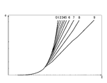
- the photoelectric conversion characteristics (hereinafter referred to as input / output characteristics) of the image sensor 102 have a plurality of input / output characteristics as shown in FIG. 4A, and charge accumulated in each pixel of the image sensor 102 that receives incident light. By changing the reset timing and reset voltage, the input / output characteristics can be changed.
- the input / output characteristics shown in FIG. 4A have nonlinear input / output characteristics in which the output voltage signal e changes nonlinearly with respect to the input luminance I. This is well known as a typical input / output characteristic of a logarithmic conversion type photoelectric conversion element.
- FIG. 4B is a graph in which the horizontal axis of the graph of FIG. 4A is converted to a logarithmic scale, and the dynamic range of the input luminance I that can be output without whiteout or blackout changes depending on the input / output characteristics. Is shown.
- one of the plurality of input / output characteristics shown in FIG. 4A is selected by an exposure control unit built in the image sensor 102 (not shown in FIG. 1) according to the imaging scene. For example, based on the brightness of the imaging scene, an input / output characteristic that captures an image with as high a contrast as possible without causing overexposure or blackout is selected and imaging is performed.
- output statistical information such as an image histogram is calculated for each frame, and the number of whiteout and blackout pixels is obtained.
- Perform detection When whiteout is detected, an input / output characteristic whose number assigned to the input / output characteristic is larger than the current input / output characteristic (wide dynamic range) is selected, and when whiteout is not detected, The input / output characteristic whose assigned number is smaller than the current input / output characteristic (the dynamic range is narrow) is selected.
- the exposure time is set longer than the current time, and when black crushing is not detected, the exposure time is set shorter than the current time.
- the input / output characteristics 303 shown in FIG. 3 correspond to the input / output characteristics 9 of FIG. 4A and the input / output characteristics 9 of FIG. 4B.
- the image sensor 102 includes two-dimensionally a plurality of pixels that output the output voltage signal e shown in FIG. 4A or 4B.
- three types of filters X which selectively transmit visible light for each wavelength and have the same transmittance for near infrared light
- Y, Z and the transmittance for each wavelength of visible light can be expressed by a linear sum of the transmittances of three types of filters, and the fourth transmittance having the same transmittance as that of the three types of filters for near-infrared light.
- the filters T are regularly arranged.
- FIG. 7A shows spectral sensitivity S that is an output value for each wavelength of the image sensor 102 in which RGB filters used in many image sensors are arranged as an example of a filter having such characteristics. That is, as shown in FIG. 5B, the three types of filters X, Y, and Z described above correspond to the red filter R, the green filter G, and the blue filter B, respectively, and the fourth filter T transmits the entire visible light. This corresponds to the transparent filter C.
- the boundary between visible light and near-infrared light is ambiguous, but it can be generally considered to be a wavelength region of about 700 nm to about 850 nm. In a wavelength region higher than this wavelength region, four types of filters are used. Since there is no difference in the spectral transmittance, the output voltage signals e of the pixels to which the light transmitted through the four types of filters respectively enter asymptotically approach each other.
- the characteristics of the four types of filters are utilized, and the output values of the four types of color filters are considered to be sufficiently asymptotic and coincident based on the characteristics of the image sensor 102 (example in FIG. 7A).
- the wavelength (near 840 nm) is regarded as the boundary between the visible light region and the near-infrared light region, and the component (visible light component) occupying the visible light region from the output voltage signal e of the image sensor 102 is retained, Only a component (near infrared light component) occupying the near infrared light region is separated and removed.
- the transmittance T T of the fourth filter T can be expressed by a linear sum of the transmittances X T , Y T , and Z T of the three types of filters X, Y, and Z. It is assumed that ⁇ , coefficient ⁇ , and coefficient ⁇ are uniquely determined. That is, the imaging apparatus 10 needs to use four color filters that satisfy the condition of (Equation 1), and this can be realized by using RGB filters used in many imaging elements as described above. Further, as the fourth filter T, a transparent filter C that transmits the entire visible light region may be used as the fourth filter T.
- a spectral sensitivity S as shown in FIG. 7A is obtained from the output value of the image sensor 102 using these four types of filters with respect to the wavelength ⁇ , and further to the image sensor 102 by gradation conversion processing (linear conversion processing) described later.
- the spectral sensitivity S shown in FIG. 7B is obtained by converting the relationship between the input luminance and the output voltage signal e output from the image sensor 102 into a linear relationship. Then, from the spectral sensitivity S shown in FIG. 7B, the values of the coefficients ⁇ , ⁇ , ⁇ satisfying (Equation 1) can be calculated.
- the values of the coefficients ⁇ , ⁇ , and ⁇ are optimum coefficients so as to be within an allowable range with respect to the true value by using the least square method from the spectral sensitivities S measured with respect to the light having a plurality of different wavelengths ⁇ . It can be set by determining the values of ⁇ , ⁇ , and ⁇ .
- the present embodiment is not limited to the RGBC filter array, but can be applied to any four types of filter arrays that can be expressed by the relational expression (Expression 1).
- the output voltage signal e generated through the RGBC filter is digitized and converted into an output signal RAW0 (12 bits).
- separation processing for separating the output signal into two output signals for use in color signal processing and luminance signal processing is performed in the signal separation unit 103.
- the two output signals after separation are exactly the same as the output signal RAW0 before separation.
- the output signal linear conversion unit 104 performs linear conversion processing (linearization) on the output signal RAW0 used for color signal processing. . That is, assuming that the image sensor 102 has a predicted linear characteristic 612 in which the output voltage signal e of the photoelectric conversion element in the image sensor 102 changes linearly with respect to the input luminance I as shown in FIG. A signal portion corresponding to a region where the input luminance I and the output voltage signal e are in a non-linear relationship is converted to a signal having a linear relationship.
- the image sensor 102 has a linear characteristic 601 in a region where the input luminance I is small, and outputs an output signal that changes linearly with respect to the input luminance I in this region. .
- the region having a large input luminance I has a nonlinear characteristic 602, and an output signal that changes nonlinearly with respect to the input luminance I is output in this region.
- the region having the linear characteristic 601 and the region having the nonlinear characteristic 602 are continuous at the connection point 605.
- the first output signals S 1 output voltage signal e photoelectric conversion element outputs of the image sensor 102.
- the linearity of the input / output characteristics is established over the entire input luminance range of the image sensor 102. That is, it is assumed that the input / output characteristic exhibits the predicted linear characteristic 612 as indicated by a dotted line in FIG. Then, from the image sensor 102, the output signal that is predicted to second output signal S 2 to be output based on the predicted linear characteristic 612.
- the output signal linear conversion unit 104 predicts that the image sensor 102 outputs the first output signal S 1 output from the image sensor 102 when the input / output characteristic assumes the predicted linear characteristic 612. It performs processing for converting the output signal S 2.
- conversion may be performed using a LUT (Look Up Table). That is, the input / output characteristics of the image sensor 102 are measured in advance for the number of all the input / output characteristics, and the output voltage signal e 1 obtained at a certain input luminance I and the input / output characteristics are linear characteristics.
- the correspondence relationship of the output voltage signal e 2 that is expected when assumed to be stored is stored in the LUT, and at the time of gradation conversion processing (linear conversion processing), the current input / output characteristic number and the actual measurement are performed. from the value of the output voltage signal e 1, it may be performed gradation conversion by referring to the value stored in the LUT corresponding thereto.
- the input / output characteristic number of the image sensor 102, the output voltage value obtained by the input / output characteristic 600, and the linearly converted output voltage value are stored.
- the input / output characteristic number of the imaging apparatus 10, the output signal RAW0 of the imaging apparatus 10, and the LUT used for gradation conversion are all handled as digital information.
- the total number of input / output characteristics required for storing these pieces of information without omission is ten.
- the number of bits necessary to express the input / output characteristics without omission is 4 bits
- the output signal RAW0 of the image sensor 102 is 12 bits
- the number of bits necessary for the LUT (output voltage value after linear conversion) is input.
- the maximum dynamic range of the luminance I is about 120 dB (1:10 6 ), it is 20 bits (> 120 dB).
- a method of performing piecewise linear conversion by predicting the position of a knee point, which is a bending point in the input / output characteristics of the image sensor 102, or an expression approximated to logarithmic characteristics There are various methods, such as a method of performing conversion according to, but in any case, the result of making the input / output characteristics linear relationship for color signal processing is the same.
- FIG. 8 is a diagram showing a detailed configuration of the color signal generation unit 105a. That is, the color signal generation unit 105a includes a first color separation unit 1051, a first linear interpolation processing unit 1052, an infrared separation unit 1053a, an infrared separation color signal correction unit 1054, and a second color separation unit 1055 ( A saturation suppression unit), a second linear interpolation processing unit 1056, an infrared-containing color signal correction unit 1057, a saturation region determination unit 1058a (color saturation detection unit), and a color signal selection unit 1059.
- a saturation suppression unit A saturation suppression unit
- second linear interpolation processing unit 1056 an infrared-containing color signal correction unit 1057
- a saturation region determination unit 1058a color saturation detection unit
- the linearized output signal RAW1 (20 bits) converted by the output signal linear conversion unit 104 is separated into three signals, a first color separation unit 1051 and a second color separation unit 1055 (saturation suppression). And a saturation region determination unit 1058a (color saturation detection unit). At this time, the three signals after separation are exactly the same as the linearized output signal RAW1 before separation.
- the first color separation unit 1051 separates the linearized output signal RAW1 into four color signals corresponding to the respective colors constituting the linearized output signal RAW1. At this time, the output of a pixel having no color signal is 0 (blank).
- the first linear interpolation processing unit 1052 calculates a pixel value expected to be observed in a blank pixel (a pixel having no color signal) generated when the first color separation unit 1051 separates the signal, as a neighboring pixel value. Is used for linear interpolation. Then, four linear color signals (R 0 , G 0 , B 0 , C 0 ) are generated in all pixels.
- red light, green light, a signal corresponding to the white light that is expected to be output from the pixels indicated by B 22 is necessary to predict by interpolating the output voltage signal e of the surrounding pixels indicated by B 22 There is.
- a red light component that is expected to be output from the pixels indicated by B 22, of the pixels adjacent to the pixels indicated by B 22, R 11, R 13 is a pixel red filter R are arranged,
- the prediction is performed by fitting the average value of the output voltage signal e of the pixel indicated by R 31 and R 33 .
- G 32 is a pixel with a green filter G is arranged Predict by applying the average value of the output voltage signal e of the pixel shown.
- white light components are expected to be output from the pixels indicated by B 22, of the pixels adjacent to the pixels indicated by B 22, at C 21, C 23 is a pixel transparent filter C are arranged Predict by applying the average value of the output voltage signal e of the pixel shown.
- the infrared separation unit 1053a performs infrared separation processing using a linear matrix on the four linear color signals (R 0 , G 0 , B 0 , C 0 ) obtained in the first linear interpolation processing unit 1052.
- the matrix operations used for specifically performing the infrared separation process are shown in (Expression 2) and (Expression 3).
- the matrix of 4 rows and 1 column on the right side of the right side represents four color signals including near infrared light after linear interpolation
- the matrix on the left side represents three color signals after separation of near infrared light.
- the color signal X since the signal includes a near-infrared light component in addition to the visible light component, the visible light component included in the signal is represented by X and the near-infrared light component is represented by i.
- the amount is X + i. Y, Z, and T are the same except that the visible light component is different from X.
- a color reproduction process described later it is calculated by calculation to be equivalent to the color signal obtained by the image sensor having the spectral sensitivity characteristic shown in FIG. 7C. Therefore, it can be seen that the resulting color signal is obtained by separating and removing almost all the near-infrared light components.
- the infrared separation color signal correction unit 1054 is a color reproduced by the imaging device 10 by a technique (linear matrix calculation based on a target color) implemented in the imaging device 10 using an imaging element having general linear characteristics. Color signal correction processing is performed so that becomes the target color.
- the infrared separation color signal correction unit 1054 performs linear matrix calculation on the three infrared separation color signals output from the infrared separation unit 1053a using (Equation 4), and the output is Correction is performed so that a color reproduced by a non-saturated non-saturated pixel (normal pixel) becomes a target color, and three corrected linear correction color signals (Xc, Yc, Zc) are output.
- the linear correction color signal obtained from the image sensor 102 having the RGBC filter described above is referred to as (R 1 , G 1 , B 1 ).
- the second color separation unit 1055 receives the linearized output signal RAW1 and separates it into four color signals (represents a blank for pixels having no color signal). 0 is inserted), but before separation, clipping is performed using a clip level predetermined for each color signal with respect to the saturation signal level (4095 in the case of 12 bits).
- Clipping processing is processing for setting the pixel value to a predetermined value when the linearized output signal RAW1 exceeds a predetermined value.
- FIG. 9A An example of clipping processing is shown in FIG. 9A.
- the signal output from the pixel in which the green filter G is arranged is larger than a predetermined value Thr, the pixel is forcibly given the predetermined value Thr.
- R_Thr Thr ⁇ G_Gain / R_Gain (Formula 5)
- G_Gain and R_Gain are parameters for adjusting the color temperature, and are a G gain representing the intensity of green and an R gain representing the intensity of red.
- B_Thr Thr ⁇ R_Gain / B_Gain (Formula 6)
- B_Gain is a parameter for adjusting the color temperature, and is a B gain representing the intensity of blue.
- the second linear interpolation processing unit 1056 performs the same linear interpolation processing as that of the first linear interpolation processing unit 1052.
- the infrared-containing color signal correction unit 1057 performs linear matrix calculation on the four color signals including near infrared light output from the second linear interpolation processing unit 1056 using (Equation 7), Correction is performed so that the color reproduced in the saturation region becomes the target color, and among the four corrected linear correction color signals (Xs, Ys, Zs, Ts), three signals (Xs, Ys, Zs) are obtained. Output.
- the linear correction color signals (R 1 , G 1 , B 1 ) calculated in this way are infrared non-separated color signals from which near infrared light is not separated.
- the color signal selection unit 1059 uses which one of the two types of linear correction color signals (infrared separated color signal and infrared unseparated color signal) generated in parallel for each pixel. Make a decision to select Therefore, first, in the saturated region determination unit 1058a (color saturation detection unit), only the saturated pixel or a peripheral pixel of the saturated pixel (a pixel affected by the saturated pixel by linear interpolation) with respect to the linearized output signal RAW1. A binary signal representing is generated.
- dilation expansion
- the binary image signal obtained as a result of this dilation processing is input to the color signal selection unit 1059 as a saturated pixel signal representing a saturated pixel.
- the region expansion processing is performed, not only the saturated pixels but also peripheral pixels considered to be affected by the saturated pixels are extracted together.
- the color signal selection unit 1059 selects which color signal is to be output from the two types of color signals according to whether or not the pixel of interest is extracted as a saturated pixel or its surrounding pixels. That is, when the above-described binary image signal is 0, it is determined that it is not a saturated pixel and is not a peripheral pixel of the saturated pixel, and the linearly corrected color signals (R 1 , G 1 , B 1) separated by infrared rays are used. ) Is selected.
- a linearly corrected color signal (R 1 , G 1 , B 1 ) that is determined as a saturated pixel or a peripheral pixel of the saturated pixel and that has been subjected to clipping processing and that has not been subjected to clipping is obtained. Selected.
- the three linearly corrected color signals are adjusted by separating the near-infrared light component from the linearized output signal RAW1 (20 bits) so as to match the human color vision characteristics.
- R 1 , G 1 , B 1 ) (signed 21 bits) is selected and output.
- this color signal will be described with reference to FIGS. 9B and 9C.
- the signal after color correction is achromatic.
- the RGB balance is lost when color correction is performed, and color misregistration occurs as shown in FIG. 9C. Therefore, as described above, when it is a saturated pixel signal, it is possible to prevent the occurrence of color misregistration by selecting the color signal subjected to the clipping process.
- the luminance signal generation unit 107 generates a luminance signal Y 1 (12 bits) from the output signal RAW0.
- the content of the processing is the same as the processing performed by the output signal linear conversion unit 104 except that color separation is not performed, and digital filtering for frequency selection is performed using a digital filter such as a low-pass filter or a band-pass filter. It is also possible to do.
- the luminance signal correction unit 108 performs contrast adjustment such as gamma correction and histogram correction on the luminance signal Y 1 to generate a luminance correction signal Y 2 (12 bits).
- the color luminance synthesis unit 109 uses the linear correction color signal and the luminance correction signal to generate a video signal to be output to the image output unit 110.
- the video signal (R 2 , G 2 , B 2 ) is obtained using the linear correction color signal (R 1 , G 1 , B 1 ) and the luminance correction signal Y 2 obtained from the image sensor 102 having the RGBC filter.
- a method for generating the data will be described step by step.
- FIG. 10 shows an internal configuration diagram of the color luminance synthesis unit 109.
- the linear correction color signals (R 1 , G 1 , B 1 ) are separated into two, and in the processing block 1091, one of the separated linear correction color signals (R 1 , G 1 , B 1 )
- the luminance component Yc is obtained using (Equation 8).
- Yc 0.299 ⁇ R 1 + 0.587 ⁇ G 1 + 0.114 ⁇ B 1 (Formula 8)
- the coefficient accumulated in each component of the linear correction color signal (R 1 , G 1 , B 1 ) is a value obtained as a conversion coefficient when converting RGB chromaticity into luminance. It is an example.
- the linear correction color signal (R 1 , G 1 , B 1 ) is determined by the value of the luminance component Yc derived by (Equation 8). ) Are respectively divided to normalize the linear correction color signals (R 1 , G 1 , B 1 ) to generate normalized color signals (Rc, Gc, Bc). This operation is also performed as a floating point operation, and the result is converted into an integer of 12 bits and output.
- Rc R 1 / Yc (Equation 9)
- Gc G 1 / Yc (Formula 10)
- Bc B 1 / Yc (Formula 11)
- the brightness correction signal Y 2 generated by the brightness signal correction unit 108 with respect to the normalized color signal (Rc, Gc, Bc). Is multiplied to generate a video signal (R 2 , G 2 , B 2 ) that is an output signal of the color luminance synthesis unit 109.
- R 2 Xc ⁇ Y 2 (Formula 12)
- G 2 Yc ⁇ Y 2 (Formula 13)
- B 2 Zc ⁇ Y 2 (Formula 14)
- the normalized color signals (Rc, Gc, Bc) is a signal having a linear characteristic
- the luminance correction signal Y 2 is a signal having the nonlinear characteristics
- the video signals they are synthesized (R 2 , G 2 , B 2 ) is a signal having nonlinear characteristics.
- Equation 15 represents that the video signal (R 2 , G 2 , B 2 ) and the luminance correction signal Y 2 have a relationship between the three primary color vectors and the luminance vector composed thereof, and the video signal (R 2 , G 2 2 , B 2 ) indicates that the luminance information of the wide dynamic range that the luminance correction signal Y 2 has is held.
- (Equation 16) represents that the color composition ratio (hue) of the linear correction color signal (R 1 , G 1 , B 1 ) and the video signal (R 2 , G 2 , B 2 ) are the same. Furthermore, in combination with (Equation 15), the signal intensity (saturation) for the luminance signal is the same. That is, it is shown that the color reproducibility that the linear color signals (R 0 , G 0 , B 0 ) had during the conversion from the linear characteristic to the nonlinear characteristic is maintained.
- the video signals (R 2 , G 2 , B 2 ) generated in this way are displayed on the image output unit 110 and presented to the vehicle occupant.
- Step S10 An imaging timing is instructed from the signal separation unit 103 to the imaging device 102, and imaging is performed.
- Step S12 The image sensor 102 receives the light transmitted through the lens system 101, performs photoelectric conversion, and outputs an output signal RAW0.
- Step S14 The signal separation unit 103 separates the output signal RAW0 into two identical output signals RAW0 and RAW0.
- Step S16 The output signal linear conversion unit 104 converts one output signal RAW0 into a linearized output signal RAW1 having linearity.
- the first color separation unit 1051 separates the linearized output signal RAW1 into four signals corresponding to each color of RGBC, and the first linear interpolation processing unit 1052 removes the blank pixels generated during the separation.
- linear interpolation is performed using the values of neighboring pixels to generate linear color signals (R 0 , G 0 , B 0 ).
- Step S20 In the infrared separation unit 1053a, an infrared light component is separated from the linear color signals R 0 , G 0 , B 0 to generate an infrared separation color signal. Further, color correction is performed by the infrared separation color signal correction unit 1054 to generate linear correction color signals (R 1 , G 1 , B 1 ).
- Step S22 The second color separation unit 1055 (saturation suppression unit) performs clipping processing, and the second linear interpolation processing unit 1056 outputs linear color signals (R 0 , G 0 , B 0 , C 0 ). Generate.
- Step S24 The infrared-containing color signal correction unit 1057 performs linear matrix calculation on the four color signals output from the second linear interpolation processing unit 1056 to generate four color-corrected color signals that have undergone color correction. To do.
- the saturation region determination unit 1058a (color saturation detection unit) performs saturation determination on the linearized output signal RAW1, and generates a binary image representing only the saturated pixels or the peripheral pixels of the saturated pixels.
- Step S28 in the luminance signal generation unit 107 generates a luminance signal Y 1 from the output signal RAW0.
- Step S30 luminance signal correction unit 108, to implement the contrast adjustment such as gamma correction and histogram correction to the luminance signal Y 1, to produce a luminance correction signal Y 2.
- Step S32 In the color luminance synthesis unit 109, the linear correction color signal (R 1 , G 1 , B 1 ) and the luminance correction signal Y 2 are synthesized to generate a video signal (R 2 , G 2 , B 2 ). .
- Step S ⁇ b> 34 The generated video signal (R 2 , G 2 , B 2 ) is output to the image output unit 110.
- the imaging element 102 selectively transmits light in different visible light regions, and is equivalent to each other in the near infrared light region.
- Three types of filters R, G, and B having transmittance, and the spectral transmittance in the visible light region are represented by a linear sum of the respective spectral transmittances of the three types of filters R, G, and B, and
- a plurality of filters R, G, B, and a transparent filter C one type of filter
- a spectral transmittance equal to the spectral transmittance of the three types of filters R, G, B C includes a plurality of pixels arranged in a predetermined pattern.
- the image sensor 102 converts the second output signal S 2 that is predicted to be output by the image sensor 102. To do.
- the color signal generation unit 105a is, for all pixels, missing more generated by interpolating the color signals, generated more linear color signals (R 0 , G 0 , B 0 ) (or linear correction color signal (R 1 , G 1 , B 1 )), the infrared separator 1053a separates the near-infrared light component and has linearity. An infrared separation color signal is generated. Then, the luminance signal generation unit 107 generates a luminance signal Y 1 having non-linearity from the first output signal S 1 , and the color luminance synthesis unit 109 generates infrared signals having a plurality of linearities thus generated.
- a video signal (R 2 , G 2 , B 2 ) is generated by combining the separated color signal and a luminance signal Y 1 (or luminance correction signal Y 2 ) having nonlinearity. Therefore, even when a subject having a large dynamic range is photographed, the luminance signal Y 1 (or luminance correction signal Y 2 ) having non-linearity does not cause whiteout or blackout, and the near-infrared light component is separated. An appropriate color image with high color reproducibility can be generated by the color signal having linearity.
- the saturation region determination unit 1058a color saturation detection unit
- the second color separation unit 1055 saturation suppression unit
- the saturation suppression unit performs a clipping process for converting the infrared unseparated color signal corresponding to the linearized output signal RAW1 in which saturation is detected into a predetermined value.
- the infrared unseparated color signal generated by the clipping process and the luminance signal Y 1 (or luminance correction signal Y 2 ) are combined to generate a video signal (R 2 , G 2 , B 2 ), while being saturated
- the region determination unit 1058a color saturation detection unit
- the correction signal Y 2 is synthesized to generate a video signal (R 2 , G 2 , B 2 ).
- the color luminance synthesis unit 109 performs linear color signals (R 0 , G 0 , B) that are infrared separated color signals generated by the first linear interpolation processing unit 1052.
- 0 linear correction color signal (R 1 , G 1 , B 1 )) is normalized by the luminance component Yc to generate a normalized color signal (Rc, Gc, Bc), or a second linear interpolation processing unit
- the linear color signal (R 0 , G 0 , B 0 ) (or linear correction color signal (R 1 , G 1 , B 1 ) which is an infrared unseparated color signal generated at 1056, is normalized by the luminance component Yc.
- a normalized color signal (Rc, Gc, Bc) is generated, the normalized color signal (Rc, Gc, Bc) generated in this way, the luminance signal Y 1 (or luminance correction signal Y 2 ), and , Are multiplied by the video signal (R 2 , G 2 , B 2 Therefore, the color signal and the luminance signal are synthesized by a simple arithmetic process, and the video signal (R 2 , G) has high color reproducibility by the color signal having no whiteout or blackout and having linearity. 2 , B 2 ).
- the image sensor 102 has been described as having a primary color filter, but this can also be realized using a complementary color filter. Furthermore, it is also possible to use a plurality of color filters in which the relationship between luminance and color is expressed by at least one expression based on human color vision characteristics.
- the color separation processing is performed in the infrared separation color signal correction unit 1054 and the infrared-containing color signal correction unit 1057, and the luminance correction processing is performed in the luminance signal correction unit 108.
- the brightness correction may be performed as necessary.
- the output signal RAW0 which is exactly the same image data
- the color signal and the luminance signal are not generated from exactly the same image data. May be.
- imaging may be performed by continuously switching input / output characteristics for color signals and luminance signals on the image sensor side, and composition may be performed using two different captured images. It is also possible to use two imaging elements having substantially equal values to capture images of two different input / output characteristics for color signals and luminance signals, and combine them.
- Example 2 which is another embodiment of the imaging apparatus according to the present invention will be described with reference to FIG.
- FIG. 12 shows a configuration of the imaging apparatus 12 according to the second embodiment.
- the imaging apparatus 12 further includes an infrared projector 120 in the imaging apparatus 10 described in the first embodiment, and illuminates the imaging field of the imaging element 102 with near-infrared light. This is applied to the purpose of monitoring the rear side.
- the near-infrared illumination light is irradiated from the infrared projector 120, and the monitoring performance in the darkness is further enhanced.
- the near-infrared light component is very large in the observed image signal, the near-infrared light component cannot be sufficiently separated in the signal processing described in the first embodiment, and the near-infrared light component cannot be sufficiently separated. Will remain. Further, if the near-infrared light component remains, more noise than usual may be generated, and appropriate color reproduction may not be performed.
- the second embodiment has been made for such a problem.
- the configuration of the imaging device 12 is that the imaging device 10 described in the first embodiment is provided with an infrared projector 120 that irradiates near-infrared illumination light, and a color signal generation unit instead of the color signal generation unit 105a.
- the difference is that 105b is provided, and a saturated region determination unit 1058b (see FIG. 13) is provided instead of the saturation region determination unit 1058a.
- FIG. 13 shows a detailed configuration of the color signal generation unit 105b.
- the configuration of the color signal generation unit 105b is different from the color signal generation unit 105a described in the first embodiment in that an infrared separation unit 1053b is provided instead of the infrared separation unit 1053a and a saturation region determination unit 1058a. The difference is that a saturated region determination unit 1058b is provided instead.
- step S26 in the flowchart of FIG. 11 when the saturated region determination unit 1058b determines the saturated pixels and determines whether or not to remove infrared rays, the infrared separation unit 1053b performs separation during this determination process. A determination item based on the amount of the generated near-infrared light component is added.
- the saturation region determination unit 1058b uses the near-infrared light component amount calculated by (Equation 18) and (Equation 19) in the pixel determined to be saturated at the saturation signal level or higher or in the infrared separation unit 1053b. A pixel exceeding a predetermined infrared light component amount reference value is determined as a saturated pixel. Thereafter, in the same manner as in the first embodiment, a binary image is generated with a saturated pixel being 1 and the others being 0, and dilation (expansion) according to the kernel size of linear interpolation is performed on the binary image. Process.
- the target of color reproducibility such as a halogen lamp signaler
- the target of color reproducibility is also determined as a saturated pixel
- the near-infrared light component signal amount and the infrared component amount reference value used for the determination are visible. You may correct
- the saturation region determination unit 1058b detects that the linearized output signal RAW1 is equal to or higher than the saturation signal level, or infrared
- the separation unit 1053b generates a saturated pixel when the near-infrared light component amount remaining after the infrared separation color signal is generated exceeds the infrared light component amount reference value
- the second color separation is performed.
- the unit 1055 saturation suppression unit
- the color luminance combining unit 109 combines the clipped infrared unseparated color signal and the luminance signal Y 1 (or luminance correction signal Y 2 ) to generate a video signal (R 2 , G 2 , B 2 ). Generate. Therefore, even when the infrared projector 120 is irradiating near infrared light toward the imaging range of the image sensor 102, generation of false color in the reflected light of the irradiated near infrared light is prevented, In addition, the occurrence of achromatic color misregistration is prevented by clipping processing, and a color close to the actual color can be output without being affected by near-infrared light.
- Example 2 demonstrated the structure provided with the infrared projector 120, when there is no infrared projector 120, you may perform the same saturation determination.
Landscapes
- Engineering & Computer Science (AREA)
- Multimedia (AREA)
- Signal Processing (AREA)
- Physics & Mathematics (AREA)
- Spectroscopy & Molecular Physics (AREA)
- Health & Medical Sciences (AREA)
- Toxicology (AREA)
- Color Television Image Signal Generators (AREA)
- Studio Devices (AREA)
- Processing Of Color Television Signals (AREA)
- Mechanical Engineering (AREA)
Abstract
明暗の差が大きい被写体を撮影した場合にも、適切なカラー画像を生成する。 異なる波長の光を選択的に透過して、近赤外光領域で互いに等しい透過率を持つ3つのフィルタ(R,G,B)と、可視光領域の透過率がフィルタ(R,G,B)の透過率の線形和で表わされ、近赤外光領域でフィルタ(R,G,B)の透過率と等しい透過率を持つ透明フィルタ(C)と、が配列された複数の画素を備えた撮像素子(102)が出力する第1の出力信号(S1)を、出力信号線形変換部(104)が、線形性を有する第2の出力信号(S2)に変換し、色信号生成部(105a)が、欠落した色信号を補間によって生成し、赤外分離部(1053a)が、色信号から近赤外光成分を分離して赤外分離色信号を生成し、輝度信号生成部(107)が、第1の出力信号(S1)から輝度信号(Y1)を生成し、色輝度合成部(109)が、赤外分離色信号と輝度信号(Y1)を合成して映像信号(R2,G2,B2)を生成する。
Description
本発明は、撮像素子を備えた撮像装置に関し、特に、明暗の差(ダイナミックレンジ)が大きい被写体を撮影した場合であっても、適切なカラー画像を生成することができる撮像装置に関するものである。
近年、交通事故の予防安全への関心が高まってきており、自動車の運転支援システムにおける要素技術として、車載監視用の撮像装置の研究開発が盛んに行われている。その中では、夜間の暗闇と高輝度な信号灯や車両灯(ヘッドライトなど)とが同時に存在する、明暗の差が非常に大きくて視界不良となり得る状況において、撮像装置の監視性能を確保すること、すなわち、視界不良となり得る状況においても信号や車線の色を判別できるように、撮像装置において、人間の色覚特性と合致した色再現性を確保することが課題となっている。
このような明暗の差が非常に大きいシーンでは、一般の撮像素子ではダイナミックレンジの限界を超えてしまうため、露出オーバーとなって階調の情報を失い、真っ白な画像になってしまう白飛びや、逆に露出アンダーとなって階調の情報を失い、真っ黒な画像になってしまう黒潰れと呼ばれる現象が発生するという課題があった。
そのため、入力輝度と出力信号の関係に非線形特性を持たせることによってダイナミックレンジを拡大することができる撮像素子が提案されている。
そして、このような非線形特性を有する撮像素子において、非線形特性を有する領域の出力信号を線形信号に変換(線形化)してから種々の色信号処理を行い、その後、画像を出力するモニタに合わせてビット幅を狭めて出力する方法が提案されている(例えば特許文献1)。
一方、暗闇において、歩行者や車線の監視性能を向上させるための手段として、近赤外線を透過する色フィルタを用いて、近赤外光領域に感度を持ったまま色再現を行うIRカラーカメラ技術の開発が行われている。
IRカラーカメラは、赤外線除去フィルタ(IRカットフィルタ)を有していないため、近赤外光領域の光に対しても感度を有しており、観測対象から放射される近赤外光、または、赤外投光器によって照射された近赤外光の反射光をIRカラーカメラで観測することによって、車両のヘッドライトが照射されていない暗い領域においても撮像を行うことが可能となる。
そして、このようなIRカラーカメラに適用できる撮像素子の開発が行われている(例えば特許文献2,3,4)。
しかしながら、特許文献1に記載された画像処理装置では、信号処理過程でビット幅を狭めることによって信号を圧縮している。これは低輝度部分の情報を削減することに相当するため、撮像素子の持つ本来のダイナミックレンジを十分に活用したカラー画像を得ることができない。したがって、例えば、低輝度の被写体と高輝度の被写体が同時に存在するシーンでは、低輝度の被写体の画像領域から得られる出力信号が、削減される下位ビットに含まれている場合、最終的に出力される画像において低輝度の被写体の色を再現できないことになる。すなわち、明暗の差(ダイナミックレンジ)が大きい被写体を撮影した場合に、それらを確実に判別できるカラー画像を生成することができないという問題があった。
また、特許文献2に記載された撮像装置では、近赤外光領域の分光反射率が色補正の際にターゲットとして使用するカラーチャートと異なっている場合に、再現される色が実際の色と異なってしまうという問題があった。例えば、木の葉や化繊の服など、近赤外光領域における分光反射率がカラーチャートと大きく異なる被写体においては、正しい色再現性を確保できない。
さらに、特許文献3,4に記載された撮像装置では、4色の色フィルタ配列を用いて、4色の分光感度特性の加算・減算を基本とする信号処理によって近赤外光成分の除去を行っている。しかしながら、この信号処理は4色いずれかの信号が飽和した、いわゆる色飽和が発生した場合には近赤外光成分の除去ができないだけでなく、実際の色とは異なる色を表わす信号が出力される、飽和偽色が発生してしまうという問題があった。
すなわち、いずれの従来技術にあっても、明暗の差が大きい被写体を撮影したときに、それらを確実に判別することができる広いダイナミックレンジを有して、なおかつ、人間の色覚特性と合致した色再現性を有する適切なカラー画像を生成することができなかった。
本発明は、上記課題に鑑みてなされたもので、明暗の差が非常に大きい状況下であっても、黒潰れと白飛びの発生が抑制されて、人間の色覚特性と合致した色再現性を有する適切なカラー画像を生成することができる撮像装置を提供することを目的とする。
本発明に係る撮像装置は、明るさに対して非線形の出力特性を有する撮像素子の持つ本来のダイナミックレンジを十分に活用するとともに、前記撮像素子に備えられた分光透過率の異なる複数のフィルタ配列によって生じる出力信号の信号差を活用することによって、明暗の差(ダイナミックレンジ)が大きい被写体を撮影した場合であっても、黒潰れや白飛びがなく、かつ色再現性が高い、適切なカラー画像を生成するものである。
すなわち、本発明に係る撮像装置は、互いに異なる可視光領域の光を選択的に透過して、かつ近赤外光領域において、互いに等しい分光透過率を持つ3種類のフィルタと、可視光領域の分光透過率が前記3種類のフィルタの各々の分光透過率の線形和で表わされて、かつ、近赤外光領域において、前記3種類のフィルタの分光透過率と等しい分光透過率を持つ1種類のフィルタと、からなる複数のフィルタが所定のパターンで配列された複数の画素を備えて、前記複数の画素から、それぞれ、前記画素に入射する入射光の輝度に応じて非線形に変化する第1の出力信号を出力する撮像素子と、前記撮像素子が入射光の輝度範囲に亘って線形に変化する第2の出力信号を出力すると仮定したときに、前記複数の画素から出力される複数の前記第1の出力信号を、それぞれ、前記第2の出力信号に変換する出力信号線形変換部と、前記第2の出力信号から、前記複数のフィルタのうち前記複数の画素にそれぞれ配列されたフィルタ以外のフィルタを配列したと仮定したときに前記複数の画素からそれぞれ出力されると予測される複数の色信号を生成する色信号生成部と、前記複数の色信号の中から、近赤外光成分が分離された複数の赤外分離色信号を生成する赤外分離部と、前記第1の出力信号から輝度信号を生成する輝度信号生成部と、前記複数の赤外分離色信号と前記輝度信号とを合成して映像信号を生成する色輝度合成部と、を有することを特徴とする。
このように構成された本発明に係る撮像装置によれば、撮像素子が、互いに異なる可視光領域の光を選択的に透過して、かつ近赤外光領域において、互いに等しい分光透過率を持つ3種類のフィルタと、可視光領域の分光透過率が前記3種類のフィルタの各々の分光透過率の線形和で表わされて、かつ、近赤外光領域において、前記3種類のフィルタの分光透過率と等しい分光透過率を持つ1種類のフィルタと、からなる複数のフィルタが所定のパターンで配列された複数の画素を備える。そして、その複数の画素から、それぞれ入射光の輝度に応じて非線形に変化する第1の出力信号を出力して、この第1の出力信号を、出力信号線形変換部において、撮像素子が入射光の入力輝度範囲に亘って線形に変化する第2の出力信号を出力すると仮定したときに、撮像素子が出力すると予測される第2の出力信号に変換する。この第2の出力信号に基づいて、色信号生成部が、全ての画素に対して、欠落した複数の色信号を補間によって生成し、生成された複数の色信号の中から、赤外分離部が近赤外光成分を分離して線形性を有する複数の赤外分離色信号を生成する。そして、輝度信号生成部が、第1の出力信号から、非線形性を有する輝度信号を生成して、色輝度合成部が、こうして生成された複数の線形性を有する赤外分離色信号と非線形性を有する輝度信号とを合成して映像信号を生成する。したがって、ダイナミックレンジが大きい被写体を撮影した場合であっても、非線形性を有する輝度信号によって白飛びや黒潰れがなく、かつ、近赤外光成分が分離された線形性を有する色信号によって色再現性が高い、適切なカラー画像を生成することができる。
本発明に係る撮像装置によれば、ダイナミックレンジが大きい被写体を撮影した場合であっても、黒潰れと白飛びの発生が抑制されて、人間の色覚特性と合致した色再現性を有する適切なカラー画像を生成することができる。
以下、本発明に係る撮像装置の実施形態について、図面を参照して説明する。
本実施例は、本発明に係る撮像装置を、車両周囲の監視を行って、撮像された画像、および撮像された画像の認識結果に基づく警報や警告灯を車両の乗員に提示する周囲監視装置に適用した例である。
[撮像装置の概略構成の説明]
まず、図面を用いて装置の構成を説明する。本実施例に係る撮像装置10は、図1に示すように車両(図示省略)に設置されて、被写体を観測するレンズ系101と、撮像素子102と、信号分離部103と、出力信号線形変換部104と、色信号生成部105aと、輝度信号生成部107と、輝度信号補正部108と、色輝度合成部109と、画像出力部110を備えている。
まず、図面を用いて装置の構成を説明する。本実施例に係る撮像装置10は、図1に示すように車両(図示省略)に設置されて、被写体を観測するレンズ系101と、撮像素子102と、信号分離部103と、出力信号線形変換部104と、色信号生成部105aと、輝度信号生成部107と、輝度信号補正部108と、色輝度合成部109と、画像出力部110を備えている。
レンズ系101は、被写体から出射した光、または被写体で反射した光を後述する撮像素子102上に導く光学系である。
レンズ系101は、車載監視用途の撮像装置の場合には、一般に狭角、広角、魚眼等のパンフォーカスレンズを用いる。しかし、その限りではなく、ズーム機構やオートフォーカス機構を備えたレンズ系を用いてもよいし、絞りやシャッターを備えたレンズ系を用いてもよい。また、画質や色再現性の向上のために光学ローパスフィルタや帯域分離フィルタや偏光フィルタ等の各種フィルタ類を備えたレンズ系を用いてもよい。
撮像素子102は光電変換素子から構成される。光電変換素子は複数の画素から構成されており、レンズ系101を通して観測された被写体の像が結像して、入力した光を、その輝度に応じた出力電圧信号eに光電変換する。光電変換された出力電圧信号eは、撮像素子102が内部に備えたアンプ(図示省略)、更に同じく内部に備えたADコンバータ(図示省略)を通してデジタル化されて、出力信号RAW0が生成される。出力信号RAW0として、例えば12ビット(0~4095)にデジタル化された信号を出力する。撮像素子102としては、最大120dB程度の入力輝度のダイナミックレンジを有する、CMOSイメージセンサやCCDイメージセンサ等の素子が用いられる。なお、撮像素子102を構成する各画素の表面には、後述するように、4種類のフィルタが規則的に配列されている。
信号分離部103は、撮像素子102に対して撮像を行うタイミングを指示するとともに、撮像素子102で撮像された出力信号RAW0を受けて、同一の2つの出力信号RAW0、RAW0に分離する。
出力信号線形変換部104は、信号分離部103で分離された出力信号RAW0,RAW0のうち一方の出力信号RAW0を、階調変換(線形化)処理によって、線形性を有する線形化出力信号RAW1に変換する。ここで行われる変換処理の内容は後述する。
色信号生成部105aは、出力信号線形変換部104で変換された線形化出力信号RAW1を、RGBC各色に対応する4つの信号に分離するとともに、分離する際に発生する空白の画素に対して、近傍の画素の値を用いて線形補間を行い、線形色信号(R0,G0,B0)を生成する。そして、さらに、線形色信号(R0,G0,B0)から赤外光成分を分離して、線形性を有する赤外分離色信号を生成するとともに、色補正を行って線形補正色信号(R1,G1,B1)を生成する。また、色信号生成部105aは、飽和画素に対してクリッピング処理を行うとともに、色飽和を起こしている飽和領域の検出を行う。そして、飽和領域を構成する画素であるか否かに応じて、適切な線形補正色信号(R1,G1,B1)を出力する。なお、色信号生成部105aは、図8に示す詳細構成を有しているが、その内容と、色信号生成部105aで行われる具体的な処理内容は後述する。
輝度信号生成部107は、信号分離部103で分離された出力信号RAW0,RAW0のうち他方の出力信号RAW0から輝度信号Y1を生成する。ここで行われる処理の内容は後述する。
輝度信号補正部108は、輝度信号生成部107で生成された輝度信号Y1を必要に応じて補正して、輝度補正信号Y2を生成する。ここで行われる処理の内容は後述する。
色輝度合成部109は、線形補正色信号(R1,G1,B1)と輝度補正信号Y2を合成して映像信号(R2,G2,B2)を生成する。ここで行われる処理の内容は後述する。
画像出力部110は、色輝度合成部109で合成された映像信号(R2,G2,B2)を出力する、例えば表示用モニタである。
以下、撮像装置10の作用について、図面を用いて順に説明する。
まず、図2に基づいて、撮像装置10の利用シーンについて説明する。図2は撮像装置10を用いて、夜間の道路を撮影したときに得られる画像を模擬的に表したものである。すなわち、道路上の被写体である、先行車201や対向車203、道路標識等による反射装置205、206、信号機207、歩行者208、レーンマーカ209などが撮像されて画像化された様子を示している。
図3は、線形の入出力特性を持つ一般的な撮像素子を用いて、図2に示す道路を撮像して画像化したときの入力輝度Iと出力電圧信号eの関係を表している。
すなわち、撮像素子102に対して、異なる2つの露光時間を与えたときの入出力特性として、露光時間が長いときの入出力特性301と、露光時間が短いときの入出力特性302、および道路上の被写体を撮像して、全ての被写体を画像化したときに、白飛びや黒潰れが発生せずに適切なカラー画像を生成することができると考えられる入出力特性303を示している。
このような夜間のシーンは明暗の差が非常に大きいため、線形の入出力特性を持つ撮像素子で撮像したのでは、ダイナミックレンジの限界を超えてしまうため、白飛びや黒潰れと呼ばれる現象が発生してしまう課題があった。
すなわち、自車両のヘッドライトや道路照明が当たっていない、もしくは自車両のヘッドライトや道路照明を反射し難いレーンマーカ209や歩行者208の分布頻度が多い入力輝度帯域304が最適に映るように、入出力特性301を与えるような露光時間を決定して撮影すると、ヘッドライト204の分布頻度が多い入力輝度帯域307やテールライト202の分布頻度が多い入力輝度帯域305における出力電圧信号eが飽和してしまい、所謂「白飛び」と呼ばれる現象が生じる(図3の領域X1が、白飛びを起こす領域を表す)。
逆に、最も明るいヘッドライト204の分布頻度が多い入力輝度帯域307が最適に映るように、入出力特性302を与えるような露光時間を決定して撮影すると、レーンマーカ209や歩行者208の分布頻度が多い入力輝度帯域304やテールライト202の分布頻度が多い入力輝度帯域305における出力電圧信号eが非常に小さくなってしまい、いわゆる「黒潰れ」と呼ばれる現象が生じる(図3の領域X2が、黒潰れを起こす領域を表す)。
ここで、入出力特性303に基づいて画像を生成すると、出力電圧信号eは、最も暗いレーンマーカ209から最も明るいヘッドライト204まで、一つの入出力特性303の白飛びも黒潰れもしない範囲に収まっている。本実施例で用いる撮像素子102の入出力特性は、入出力特性303にほぼ一致しているものとする。
次に、撮像装置10の作用について、順を追って説明する。
[撮像素子の入出力特性の説明]
撮像素子102の光電変換特性(以下、入出力特性と呼ぶ)は、図4Aに示すように複数の入出力特性を備えており、入射光を受光した撮像素子102の各画素に蓄積される電荷のリセットタイミングやリセット電圧を変更することによって、入出力特性を変更することができる。
撮像素子102の光電変換特性(以下、入出力特性と呼ぶ)は、図4Aに示すように複数の入出力特性を備えており、入射光を受光した撮像素子102の各画素に蓄積される電荷のリセットタイミングやリセット電圧を変更することによって、入出力特性を変更することができる。
そして、図4Aに示す入出力特性は、入力輝度Iに対して出力電圧信号eが非線形に変化する非線形の入出力特性を有している。これは、対数変換型の光電変換素子の代表的な入出力特性としてよく知られたものである。
なお、図4Bは、図4Aのグラフの横軸を対数目盛りに変換したグラフであり、入出力特性の違いによって、白飛びや黒潰れせずに出力できる入力輝度Iのダイナミックレンジが変化することを示している。
そして、図4A,図4Bでは、入出力特性に付与した番号が大きいほど、入力輝度Iのダイナミックレンジが広い特性を有している。
なお、図4Aに記載された複数の入出力特性は、撮像シーンに応じて、図1に図示しない、撮像素子102に内蔵された露光制御部によって1つ選択される。例えば、撮像シーンの明るさに基づいて、白飛びや黒潰れが発生せずに、できるだけコントラストが高い画像が撮像される入出力特性が選択されて、撮像が行われる。
具体的には、前記した露光制御部において、1フレーム毎に画像のヒストグラム等の出力統計情報を算出して、白飛び、黒潰れの画素数を取得し、閾値判定によって白飛び、黒潰れの検出を行う。白飛びが検出された場合、入出力特性に付与された番号が現在の入出力特性よりも大きい(ダイナミックレンジが広い)入出力特性が選択されて、白飛びが検出されない場合、入出力特性に付与された番号が現在の入出力特性よりも小さい(ダイナミックレンジが狭い)入出力特性が選択される。
また、黒潰れが検出された場合、露光時間を現在より大きくして、黒潰れが検出されない場合、露光時間を現在より短くする。
図3に示した入出力特性303は、図4Aの入出力特性9、および図4Bの入出力特性9に対応するものである。
[撮像素子のフィルタ構成の説明]
撮像素子102は、図4Aまたは図4Bに示す出力電圧信号eを出力する複数の画素を二次元的に備えている。
撮像素子102は、図4Aまたは図4Bに示す出力電圧信号eを出力する複数の画素を二次元的に備えている。
各画素の受光面の表面には、図5Aに示すように、可視光を波長毎に選択的に透過し、かつ近赤外光に対しては互いに等しい透過率をもつ3種類のフィルタX,Y,Zと可視光の波長毎の透過率を3種類のフィルタの透過率の線形和で表すことができ、かつ近赤外光に対しては3種類のフィルタと等しい透過率をもつ第4のフィルタTが規則的に配列されている。
図7Aは、このような特性を有するフィルタの例として、多くの撮像素子に用いられているRGBフィルタを配列した撮像素子102の波長毎の出力値である分光感度Sを示している。すなわち、図5Bのように、前述した3種類のフィルタX,Y,Zが、それぞれ、赤色フィルタR,緑色フィルタG,青色フィルタBに対応し、第4のフィルタTが、可視光全体を透過する透明フィルタCに対応している。
図7Aにおいて、可視光と近赤外光の境目は曖昧であるが、一般的に約700nm~約850nmの波長領域と考えてよく、この波長領域よりも高波長領域では、4種類のフィルタの分光透過率に差が生じなくなるため、4種類のフィルタを透過した光がそれぞれ入射した画素の出力電圧信号eは互いに漸近する。
本実施例は、この4種類のフィルタの特性を活用したものであり、撮像素子102の特性に基づき4種類の色フィルタの出力値が十分に漸近して一致するとみなした点(図7Aの例では、波長840nm付近)を可視光領域と近赤外光領域の境界とみなして、撮像素子102の出力電圧信号eの中から、可視光領域に占める成分(可視光成分)を保持して、近赤外光領域に占める成分(近赤外光成分)のみを分離、除去することを特徴としている。
次に、前記4種類のフィルタX,Y,Z,Tの特性に関して説明する。前記4種類のフィルタX,Y,Z,Tの可視光領域の任意の波長における透過率を、それぞれXT、YT、ZT、TTとすると、それらの関係は(式1)のように表せる。
TT=αXT+βYT+γZT (式1)
TT=αXT+βYT+γZT (式1)
このように、第4のフィルタTの透過率TTは3種類のフィルタX,Y,Zの各透過率XT、YT、ZTの線形和で表すことができ、正負を問わない係数α、係数β、係数γが一意に定まるものとする。すなわち、撮像装置10は(式1)の条件を満たす4色のフィルタを使用する必要があるが、これは、前述したように、多くの撮像素子に用いられるRGBフィルタを用いることによって実現できる。そして、さらに、第4のフィルタTとして、可視光領域全体を透過する透明(Clear)フィルタCを用いればよい。
これら4種類のフィルタを用いた撮像素子102の波長λに対する出力値から、図7Aのような分光感度Sが得られ、更に、後述する階調変換処理(線形変換処理)によって、撮像素子102への入力輝度と撮像素子102から出力される出力電圧信号eとの関係を線形関係に変換することによって、図7Bに示す分光感度Sが得られる。そして、図7Bに示す分光感度Sから、(式1)を満たす係数α,β,γの値を算出することができる。
係数α,β,γの値は、複数の異なる波長λの光に対して計測された分光感度Sから、最小二乗法を用いて、真値に対して許容範囲内に収まるように最適な係数α,β,γの値を定めることによって設定できる。そして、本実施例は、RGBCフィルタ配列に限らず、(式1)の関係式で表すことができる任意の4種類のフィルタ配列に適用することができる。
撮像素子102内において、前記RGBCフィルタを通して生成された出力電圧信号eは、デジタル化されて出力信号RAW0(12ビット)に変換される。そして、まず、信号分離部103において色信号処理と輝度信号処理に用いるための2つの出力信号に分離する分離処理が行われる。分離後の2つの出力信号は、分離前の出力信号RAW0と全く同一のものである。
[線形変換処理の説明]
次に、信号分離部103において分離された2つの出力信号RAW0,RAW0のうち、色信号処理に用いられる出力信号RAW0に対して、出力信号線形変換部104において線形変換処理(線形化)を行う。すなわち、撮像素子102が、図6に示すように、入力輝度Iに対して、撮像素子102内の光電変換素子の出力電圧信号eが線形に変化する予測線形特性612を有すると仮定して、入力輝度Iと出力電圧信号eとが非線形関係にある領域に該当する信号部分を、線形関係をもつ信号になるように変換する。
次に、信号分離部103において分離された2つの出力信号RAW0,RAW0のうち、色信号処理に用いられる出力信号RAW0に対して、出力信号線形変換部104において線形変換処理(線形化)を行う。すなわち、撮像素子102が、図6に示すように、入力輝度Iに対して、撮像素子102内の光電変換素子の出力電圧信号eが線形に変化する予測線形特性612を有すると仮定して、入力輝度Iと出力電圧信号eとが非線形関係にある領域に該当する信号部分を、線形関係をもつ信号になるように変換する。
撮像素子102は、図6の入出力特性600に示すように、入力輝度Iが小さい領域では線形特性601を有し、この領域では、入力輝度Iに対して線形に変化する出力信号を出力する。
また、入力輝度Iが大きい領域では非線形特性602を有し、この領域では、入力輝度Iに対して非線形に変化する出力信号を出力する。
そして、線形特性601を有する領域と非線形特性602を有する領域とは、接続点605において連続している。なお、撮像素子102内の光電変換素子が出力する出力電圧信号eを第1の出力信号S1とする。
このとき、撮像素子102の全入力輝度範囲に亘って、入出力特性の線形性が成り立つと仮定する。すなわち、図6の点線で示すように、入出力特性が予測線形特性612を呈すると仮定する。そして、撮像素子102から、この予測線形特性612に基づいて出力されると予測される出力信号を第2の出力信号S2とする。
出力信号線形変換部104では、撮像素子102が出力した第1の出力信号S1を、入出力特性が予測線形特性612をなすと仮定したときに、撮像素子102が出力すると予測される第2の出力信号S2に変換する処理を行う。
すなわち、図6の場合、入力輝度I1に対して入出力特性600によって得られた出力電圧信号がe1であり、入出力特性が予測線形特性612をなすと仮定したときに、入力輝度I1に対して予測される出力電圧信号がe2であるとすると、出力電圧信号e1をe2/e1倍する処理が行われる。
線形化の方法には、様々なものが存在するが、例えば、LUT(Look Up Table)を用いて変換すればよい。すなわち、あらかじめ撮像素子102の入出力特性を全ての入出力特性の番号の数だけ測定しておき、ある入力輝度Iのときに得られた出力電圧信号e1と、入出力特性が線形特性をなすと仮定したときに予想される出力電圧信号e2の対応関係をLUTに記憶しておき、階調変換処理(線形変換処理)時には、現在の入出力特性の番号と、実際に計測された出力電圧信号e1の値から、そこに対応するLUTに記憶された値を参照して階調変換を行えばよい。
このとき作成されるLUTには、撮像素子102の入出力特性の番号と、入出力特性600によって得られた出力電圧値と、線形変換された出力電圧値が記憶される。
なお、撮像装置10の入出力特性の番号,撮像装置10の出力信号RAW0,階調変換を行うために用いるLUTは、いずれもデジタル情報として取り扱う。実施例1において、これらの情報を漏れなく記憶しておくために必要なビット数は、例えば図4Aの入出力特性を有する撮像素子102を用いる場合、入出力特性の総数は10通りであるので、入出力特性を漏れなく表現するのに必要なビット数は4ビット、撮像素子102の出力信号RAW0は12ビット、そして、LUTに必要なビット数(線形変換後の出力電圧値)は、入力輝度Iのダイナミックレンジが最大120dB(1:106)程度であることを考慮して、20ビット(>120dB)となる。
そして、この階調変換処理(線形変換処理)によって、12ビットの出力信号RAW0から、20ビットの線形化出力信号RAW1が得られる。
階調変換処理を行う方法には、この他にも、撮像素子102の入出力特性における屈曲点であるニーポイントの位置を予測して区分線形変換を行う方法や、対数特性に近似して式による変換を行う方法など、様々考えられるが、いずれも、色信号処理のために入出力特性を線形な関係にするという結果は同じになる。
[色信号の線形補間処理の説明]
次に、色信号生成部105aで行わる色再現処理について、図8を用いて説明する。
次に、色信号生成部105aで行わる色再現処理について、図8を用いて説明する。
図8は、色信号生成部105aの詳細な構成を示す図である。すなわち、色信号生成部105aは、第1色分離部1051と、第1線形補間処理部1052と、赤外分離部1053aと、赤外分離色信号補正部1054と、第2色分離部1055(飽和抑制部)と、第2線形補間処理部1056と、赤外含有色信号補正部1057と、飽和領域判定部1058a(色飽和検出部)と、色信号選択部1059を備えている。
出力信号線形変換部104(図1参照)によって変換された線形化出力信号RAW1(20ビット)は3つの信号に分離されて、第1色分離部1051と、第2色分離部1055(飽和抑制部)、および飽和領域判定部1058a(色飽和検出部)に入力される。このとき、分離後の3つの信号は、分離前の線形化出力信号RAW1と全く同一のものである。
第1色分離部1051は、線形化出力信号RAW1を、線形化出力信号RAW1を構成する各色に対応する4つの色信号に分離する。このとき、色信号がない画素は出力を0(空白)とする。
第1線形補間処理部1052は、第1色分離部1051において信号を分離する際に発生した空白の画素(色信号がない画素)において観測されると予想される画素値を、近傍の画素値を用いて線形補間する。そして、全ての画素において、それぞれ4つの線形色信号(R0,G0,B0,C0)を生成する。
この線形補間の方法について、図5Cを用いて具体的に説明する。図5Cのように配列されたフィルタにおいて、例えば、B22で示される画素の表面には、青色光を透過するフィルタが配列されている。したがって、B22で示される画素からは、青色に対応する出力電圧信号eが得られるのみである。
したがって、B22で示される画素から出力されると予想される赤色光,緑色光,白色光に対応する信号は、B22で示される画素の周囲の出力電圧信号eを補間して予測する必要がある。
例えば、B22で示される画素から出力されると予想される赤色光成分は、B22で示される画素に隣接する画素のうち、赤色フィルタRが配列された画素であるR11,R13,R31,R33で示される画素の出力電圧信号eの平均値を当てはめることによって予測する。
また、B22で示される画素から出力されると予想される緑色光成分は、B22で示される画素に隣接する画素のうち、緑色フィルタGが配列された画素であるG12,G32で示される画素の出力電圧信号eの平均値を当てはめることによって予測する。
そして、B22で示される画素から出力されると予想される白色光成分は、B22で示される画素に隣接する画素のうち、透明フィルタCが配列された画素であるC21,C23で示される画素の出力電圧信号eの平均値を当てはめることによって予測する。
なお、このとき、単に補間するだけではなく、ローパスフィルタや、バンドパスフィルタなどのディジタルフィルタを用いて周波数選択のためのディジタルフィルタリングを実施して、欠落した色信号を予測してもよい。
[赤外光分離処理の説明]
赤外分離部1053aは、第1線形補間処理部1052において得られた前記4つの線形色信号(R0,G0,B0,C0)に対してリニアマトリクスによる赤外分離処理を行う。具体的に赤外分離処理を行うために用いる行列演算を(式2)及び(式3)に示す。


赤外分離部1053aは、第1線形補間処理部1052において得られた前記4つの線形色信号(R0,G0,B0,C0)に対してリニアマトリクスによる赤外分離処理を行う。具体的に赤外分離処理を行うために用いる行列演算を(式2)及び(式3)に示す。
(式2)において右辺右側の4行1列の行列は、線形補間後の、近赤外光を含む4つの色信号を表し、左辺の行列は近赤外光分離後の3つの色信号を表している。例えば色信号Xの場合は、信号には可視光成分の他に近赤外光成分が含まれているため、信号に含まれる可視光成分をX、近赤外光成分をiで表して信号量はX+iとなる。Y,Z,Tについても、可視光成分がXと異なる以外は同様になる。
ここで(式1)を用いて(式2)の右辺を展開して(式3)を代入すると、(式2)の左辺が得られる。即ち、あらかじめ(式1)の係数α、β、γを求めておいて(式3)を導出しておくことで、近赤外光を含む線形色信号(R0,G0,B0,C0)に対して、比較的簡単な線形演算を行うことによって赤外分離された線形色信号を計算することが可能である。
実際にRGBCフィルタからなる撮像素子102を用いた場合、X=R、Y=G、Z=B、T=Cとして、図7Bの分光感度特性からα、β、γを求めると、α=0.5、β=0.6、γ=0.6となる。そして、後述する色再現処理を適用すると、図7Cの分光感度特性を持つ撮像素子で得られる色信号と同等になることが計算により求められる。したがって、結果として得られる色信号は、近赤外光成分がほとんど分離除去されたものであることがわかる。
赤外分離色信号補正部1054は、一般的な線形特性を持つ撮像素子を用いた撮像装置10で実施されている技術(ターゲットカラーに基づくリニアマトリクス演算)により、撮像装置10によって再現される色がターゲットカラーとなるように色信号補正処理を行う。
具体的には、赤外分離色信号補正部1054において、赤外分離部1053aから出力される3つの赤外分離色信号に対して、(式4)を用いてリニアマトリクス演算を行い、出力が飽和していない非飽和画素(通常画素)で再現される色がターゲットカラーとなるように補正して、補正された3つの線形補正色信号(Xc,Yc,Zc)を出力する。

特に、前述したRGBCフィルタを備えた撮像素子102から得られた線形補正色信号を(R1,G1,B1)と呼ぶことにする。線形補正色信号(R1,G1,B1)は、(式4)において、X=R、Y=G、Z=B、T=Cと置き換えることによって算出することができる。
[クリッピング処理の説明]
第2色分離部1055(飽和抑制部)は、第1色分離部1051と同様に、線形化出力信号RAW1が入力されて、4つの色信号に分離(色信号がない画素には空白を表す0を挿入)されるが、分離前に、飽和信号レベル(12ビットの場合は4095)に対して色信号毎に予め定められたクリップレベルを用いてクリッピングを行う。
第2色分離部1055(飽和抑制部)は、第1色分離部1051と同様に、線形化出力信号RAW1が入力されて、4つの色信号に分離(色信号がない画素には空白を表す0を挿入)されるが、分離前に、飽和信号レベル(12ビットの場合は4095)に対して色信号毎に予め定められたクリップレベルを用いてクリッピングを行う。
クリッピング処理とは、線形化出力信号RAW1が、予め決めておいた所定の値を超えていたときに、その画素値を予め決めておいた所定の値に設定する処理のことである。
クリッピング処理の1例を図9Aに示す。例えば、緑色フィルタGが配列された画素から出力された信号が、予め決めた所定値Thrよりも大きいときは、その画素に強制的に所定値Thrを与える。
そして、このとき、同じ輝度の白色光が、赤色フィルタRが配列された画素に入射したときに、その画素から出力される信号も飽和するように、赤色フィルタが配列された画素に対する所定値R_Thrが設定される。ここで、R_Thrの値は、(式5)によって算出する。
R_Thr=Thr×G_Gain/R_Gain (式5)
ここで、G_Gain,R_Gainはそれぞれ、色温度を調整するパラメータであり、緑色の強さを表わすGゲインと、赤色の強さを表わすRゲインである。
R_Thr=Thr×G_Gain/R_Gain (式5)
ここで、G_Gain,R_Gainはそれぞれ、色温度を調整するパラメータであり、緑色の強さを表わすGゲインと、赤色の強さを表わすRゲインである。
そして、同様にして、青色フィルタが配列された画素に対する所定値B_Thrが設定される。ここで、B_Thrの値は、(式6)によって算出する。
B_Thr=Thr×R_Gain/B_Gain (式6)
ここで、B_Gainは、色温度を調整するパラメータであり、青色の強さを表わすBゲインである。
B_Thr=Thr×R_Gain/B_Gain (式6)
ここで、B_Gainは、色温度を調整するパラメータであり、青色の強さを表わすBゲインである。
その後、第2線形補間処理部1056で第1線形補間処理部1052と同様の線形補間処理を行う。また、赤外含有色信号補正部1057は、第2線形補間処理部1056から出力される近赤外光を含む4つの色信号に対して、(式7)を用いてリニアマトリクス演算を行い、飽和領域で再現される色がターゲットカラーとなるように補正して、補正された4つの線形補正色信号(Xs,Ys,Zs,Ts)のうち、(Xs,Ys,Zs)の3信号を出力する。

なお、前述したRGBCフィルタを備えた撮像素子102の場合、(式7)において、X=R、Y=G、Z=B、T=Cと置き換えることによって、線形補正色信号(R1,G1,B1)が算出される。こうして算出される線形補正色信号(R1,G1,B1)は、近赤外光が分離されていない赤外未分離色信号である。
[飽和領域判定処理の説明]
色信号選択部1059は、画素単位で並行して生成される前記2種類の線形補正色信号(赤外分離色信号、赤外未分離色信号)のうち、どちらの線形補正色信号を使用するかを選択するための判定を行う。そのため、まず、飽和領域判定部1058a(色飽和検出部)において、線形化出力信号RAW1に対して、飽和画素、または飽和画素の周辺画素(線形補間で飽和画素の影響を受けている画素)のみを表わす二値信号を生成する。
色信号選択部1059は、画素単位で並行して生成される前記2種類の線形補正色信号(赤外分離色信号、赤外未分離色信号)のうち、どちらの線形補正色信号を使用するかを選択するための判定を行う。そのため、まず、飽和領域判定部1058a(色飽和検出部)において、線形化出力信号RAW1に対して、飽和画素、または飽和画素の周辺画素(線形補間で飽和画素の影響を受けている画素)のみを表わす二値信号を生成する。
具体的には、飽和信号レベル以上で飽和と判定された画素を1とし、それ以外を0とする二値画像に対して、線形補間処理を行った際のカーネルサイズに合わせたダイレーション(膨張)処理を行って、このダイレーション処理の結果得られた二値画像信号を、飽和画素を表わす飽和画素信号として色信号選択部1059へ入力する。このとき、領域の膨張処理を行うため、飽和画素とともに、飽和画素の影響を受けていると考えられる周辺画素も合わせて抽出される。
色信号選択部1059は、着目した画素が、飽和画素、またはその周辺画素として抽出されているか否かに従って、2種類の色信号のうち、どちらの色信号を出力するかの選択を行う。すなわち、前述した二値画像信号が0のときは、飽和画素ではなく、かつ飽和画素の周辺画素でもないと判断されて、赤外分離された線形補正色信号(R1,G1,B1)が選択される。
一方、二値画像信号が1のときは、飽和画素または、飽和画素の周辺画素と判断されて、クリッピング処理された赤外未分離の線形補正色信号(R1,G1,B1)が選択される。
以上により、線形化出力信号RAW1(20ビット)から、人間の色覚特性に一致するように、近赤外光成分が分離されて、彩度や色相などが調整された3つの線形補正色信号(R1、G1、B1)(符号付き21ビット)が選択されて出力される。
この色信号の選択を図9B,図9Cを用いて説明する。図9B,図9Cに示すように、非飽和画素、またはクリッピング処理を行った飽和画素であれば、色補正後の信号は無彩色となる。これに対してクリッピング処理を行わない飽和画素では、色補正を行った際にRGBのバランスが崩れて、図9Cに示すように色ずれが発生する。したがって、前述したように、飽和画素信号であるときには、クリッピング処理を行った色信号を選択することによって、色ずれの発生を防止することができる。
[色輝度合成による色再現処理の説明]
信号分離部103によって分離された2つの出力信号RAW0,RAW0のうち、色信号処理に用いない出力信号RAW0は、輝度信号処理に利用される。
信号分離部103によって分離された2つの出力信号RAW0,RAW0のうち、色信号処理に用いない出力信号RAW0は、輝度信号処理に利用される。
輝度信号生成部107は、出力信号RAW0から輝度信号Y1(12ビット)を生成する。処理の内容は、出力信号線形変換部104で行う処理と、色分離をしない点以外は同様であり、ローパスフィルタや、バンドパスフィルタなどのディジタルフィルタを用いて周波数選択のためのディジタルフィルタリングを実施することも可能である。
輝度信号補正部108は、輝度信号Y1に対してガンマ補正やヒストグラム補正等のコントラスト調整を実施して、輝度補正信号Y2(12ビット)を生成する。
そして、線形補正色信号と輝度補正信号を用いて、色輝度合成部109おいて、画像出力部110に出力する映像信号を生成する。
[色輝度合成処理の説明]
以下、RGBCフィルタを備えた撮像素子102から得られた線形補正色信号(R1,G1,B1)と輝度補正信号Y2を用いて、映像信号(R2,G2,B2)を生成する方法について、順を追って説明する。
以下、RGBCフィルタを備えた撮像素子102から得られた線形補正色信号(R1,G1,B1)と輝度補正信号Y2を用いて、映像信号(R2,G2,B2)を生成する方法について、順を追って説明する。
図10に色輝度合成部109の内部構成図を示す。まず、線形補正色信号(R1、G1、B1)を2つに分離し、処理ブロック1091において、分離した一方の線形補正色信号(R1、G1、B1)から、それらの輝度成分Ycを(式8)を用いて求める。
Yc = 0.299×R1+0.587×G1+0.114×B1 (式8)
Yc = 0.299×R1+0.587×G1+0.114×B1 (式8)
(式8)において、線形補正色信号(R1、G1、B1)の各成分に積算される係数は、それぞれ、RGB色度を輝度に変換する際の変換係数として求められた値の一例である。
(式8)の演算は、入力される線形補正色信号(R1,G1,B1)(符号付き21ビット)の値の範囲が広いため、線形補正色信号(R1,G1,B1)を浮動小数点に変換して、浮動小数点演算として行う。
次に、処理ブロック1092において、(式9)から(式11)で示すように、(式8)で導出された輝度成分Ycの値によって、線形補正色信号(R1、G1、B1)の各成分をそれぞれ除算して、線形補正色信号(R1、G1、B1)の正規化を行い、正規化色信号(Rc,Gc,Bc)を生成する。この演算も浮動小数点演算として行われ、結果は12ビットに整数化されて出力される。
Rc = R1/Yc (式9)
Gc = G1/Yc (式10)
Bc = B1/Yc (式11)
Rc = R1/Yc (式9)
Gc = G1/Yc (式10)
Bc = B1/Yc (式11)
そして、処理ブロック1093において、(式12)から(式14)で示すように、正規化色信号(Rc,Gc,Bc)に対して、輝度信号補正部108によって生成された輝度補正信号Y2を乗算して、色輝度合成部109の出力信号である映像信号(R2、G2、B2)が生成される。
R2 = Xc×Y2 (式12)
G2 = Yc×Y2 (式13)
B2 = Zc×Y2 (式14)
R2 = Xc×Y2 (式12)
G2 = Yc×Y2 (式13)
B2 = Zc×Y2 (式14)
ここで、留意すべきは、正規化色信号(Rc,Gc,Bc)は線形特性を持つ信号であり、輝度補正信号Y2は非線形特性を持つ信号であるため、それらが合成された映像信号(R2、G2、B2)は非線形特性を持つ信号となることである。
このとき、線形補正色信号(R1、G1、B1)と輝度補正信号Y2と映像信号(R2、G2、B2)の間には、(式15),(式16)の関係式が成り立つ。但し、演算時のビット幅縮小に伴う誤差による影響は、十分小さいものとしている。
Y2 = 0.299×R2+0.587×G2+0.114×B2 (式15)
R1:G1:B1 = R2:G2:B2 (式16)
Y2 = 0.299×R2+0.587×G2+0.114×B2 (式15)
R1:G1:B1 = R2:G2:B2 (式16)
(式15)は、映像信号(R2、G2、B2)と輝度補正信号Y2が3原色ベクトルとそれからなる輝度ベクトルの関係であることを表しており、映像信号(R2、G2、B2)が輝度補正信号Y2の持つ広ダイナミックレンジの輝度情報を保持していることを示している。
また、(式16)は、線形補正色信号(R1、G1、B1)と映像信号(R2、G2、B2)の色の組成比(色相)が同一であることを表していて、さらに、(式15)と合わせて、輝度信号に対する信号強度(彩度)が同一であることを表している。すなわち、線形特性から非線形特性への変換の際に、線形色信号(R0,G0,B0)が有していた色再現性が保持されていることを示している。
こうして生成された映像信号(R2、G2、B2)は、画像出力部110に表示されて、車両の乗員に提示される。
[処理の流れの説明]
次に、図11のフローチャートを用いて、実施例1の一連の処理の流れを説明する。
次に、図11のフローチャートを用いて、実施例1の一連の処理の流れを説明する。
(ステップS10)信号分離部103から撮像素子102に対して、撮像タイミングが指示されて、撮像が行われる。
(ステップS12)撮像素子102は、レンズ系101を透過した光を受光して、光電変換を行い、出力信号RAW0を出力する。
(ステップS14)信号分離部103において、出力信号RAW0を同一の2つの出力信号RAW0,RAW0に分離する。
(ステップS16)出力信号線形変換部104において、一方の出力信号RAW0を、線形性を有する線形化出力信号RAW1に変換する。
(ステップS18)第1色分離部1051において、線形化出力信号RAW1をRGBC各色に対応する4つの信号に分離して、第1線形補間処理部1052において、分離の際に発生する空白の画素に対して、近傍の画素の値を用いて線形補間を行い、線形色信号(R0,G0,B0)を生成する。
(ステップS20)赤外分離部1053aにおいて、線形色信号R0,G0,B0から赤外光成分を分離して、赤外分離色信号を生成する。さらに、赤外分離色信号補正部1054で色補正を行って線形補正色信号(R1,G1,B1)を生成する。
(ステップS22)第2色分離部1055(飽和抑制部)において、クリッピング処理を行い、さらに、第2線形補間処理部1056において、線形色信号(R0,G0,B0,C0)を生成する。
(ステップS24)赤外含有色信号補正部1057において、第2線形補間処理部1056から出力される4つの色信号に対してリニアマトリクス演算を行い、色補正された4つの線形補正色信号を生成する。
(ステップS26)飽和領域判定部1058a(色飽和検出部)において、線形化出力信号RAW1に対して飽和判定を行い、飽和画素、または飽和画素の周辺画素のみを表わす二値画像を生成する。
(ステップS28)輝度信号生成部107において、出力信号RAW0から輝度信号Y1を生成する。
(ステップS30)輝度信号補正部108において、輝度信号Y1に対してガンマ補正やヒストグラム補正等のコントラスト調整を実施して、輝度補正信号Y2を生成する。
(ステップS32)色輝度合成部109において、線形補正色信号(R1,G1,B1)と輝度補正信号Y2を合成して映像信号(R2,G2,B2)を生成する。
(ステップS34)生成された映像信号(R2,G2,B2)を、画像出力部110に出力する。
以上、説明したように、実施例1に係る撮像装置10によれば、撮像素子102が、互いに異なる可視光領域の光を選択的に透過して、かつ近赤外光領域において、互いに等しい分光透過率を持つ3種類のフィルタR,G,Bと、可視光領域の分光透過率が前記3種類のフィルタR,G,Bの各々の分光透過率の線形和で表わされて、かつ、近赤外光領域において、前記3種類のフィルタR,G,Bの分光透過率と等しい分光透過率を持つ透明フィルタC(1種類のフィルタ)と、からなる複数のフィルタR,G,B,Cが所定のパターンで配列された複数の画素を備える。そして、その複数の画素から、それぞれ入射光の輝度に応じて非線形に変化する第1の出力信号S1を出力して、この第1の出力信号S1を、出力信号線形変換部104において、撮像素子102が入射光の入力輝度範囲に亘って線形に変化する第2の出力信号S2を出力すると仮定したときに、撮像素子102が出力すると予測される第2の出力信号S2に変換する。この第2の出力信号S2に基づいて、色信号生成部105aが、全ての画素に対して、欠落した複数の色信号を補間して生成し、生成された複数の線形色信号(R0,G0,B0)(または線形補正色信号(R1,G1,B1))の中から、赤外分離部1053aが、近赤外光成分を分離して線形性を有する複数の赤外分離色信号を生成する。そして、輝度信号生成部107が、第1の出力信号S1から、非線形性を有する輝度信号Y1を生成して、色輝度合成部109が、こうして生成された複数の線形性を有する赤外分離色信号と非線形性を有する輝度信号Y1(または輝度補正信号Y2)とを合成して映像信号(R2,G2,B2)を生成する。したがって、ダイナミックレンジが大きい被写体を撮影した場合であっても、非線形性を有する輝度信号Y1(または輝度補正信号Y2)によって白飛びや黒潰れがなく、かつ、近赤外光成分が分離された線形性を有する色信号によって色再現性が高い適切なカラー画像を生成することができる。
また、実施例1に係る撮像装置10によれば、飽和領域判定部1058a(色飽和検出部)において、線形化出力信号RAW1が飽和していることが検出されたときには、第2色分離部1055(飽和抑制部)において、飽和が検出された線形化出力信号RAW1に対応する赤外未分離色信号を、予め決められた所定の値に変換するクリッピング処理を行う。そして、クリッピング処理によって生成された赤外未分離色信号と輝度信号Y1(または輝度補正信号Y2)を合成して映像信号(R2,G2,B2)を生成し、一方、飽和領域判定部1058a(色飽和検出部)において、線形化出力信号RAW1が飽和していることが検出されないときには、赤外分離部1053aから出力される赤外分離色信号と輝度信号Y1(または輝度補正信号Y2)を合成して映像信号(R2,G2,B2)を生成する。そのため、色飽和が発生しないときは赤外成分を含まない人間の色覚特性にほぼ等しい色を出力できるとともに、色飽和が発生したときであっても飽和偽色の発生が防止され、かつクリッピング処理によって無彩色の色ずれの発生が防止されて、人間の色覚特性に違和感なく実際の色に近い色を出力することができる。
また、実施例1に係る撮像装置10によれば、色輝度合成部109が、第1線形補間処理部1052で生成された赤外分離色信号である線形色信号(R0,G0,B0)(または線形補正色信号(R1,G1,B1))を輝度成分Ycによって正規化して正規化色信号(Rc,Gc,Bc)を生成し、または、第2線形補間処理部1056で生成された赤外未分離色信号である線形色信号(R0,G0,B0)(または線形補正色信号(R1,G1,B1)を輝度成分Ycによって正規化して正規化色信号(Rc,Gc,Bc)を生成する。そして、このようにして生成された正規化色信号(Rc,Gc,Bc)と、輝度信号Y1(または輝度補正信号Y2)と、を乗算することによって映像信号(R2,G2,B2)を生成する。したがって、簡単な演算処理によって色信号と輝度信号を合成して、白飛びや黒潰れがなく、かつ線形性を有する色信号によって色再現性が高い映像信号(R2,G2,B2)を生成することができる。
なお、本実施例では、撮像素子102が原色系の色フィルタを有するものとして説明したが、これは、補色系の色フィルタを用いても実現可能である。さらに、人間の色覚特性に基づき、輝度と色との関係が少なくとも1つの式で表わされる複数の色フィルタを用いることも可能である。
また、本実施例は、赤外分離色信号補正部1054、赤外含有色信号補正部1057において色補正処理を行い、輝度信号補正部108において輝度補正処理を行う構成としたが、この色補正と輝度補正は、必要に応じて適宜実施すればよい。
さらに、本実施例は、全く同一の画像データである出力信号RAW0を色信号と輝度信号に分離し、合成する例を示したが、色信号と輝度信号は全く同一の画像データから生成されなくてもよい。例えば、撮像素子側で色信号用と輝度信号用に入出力特性を連続的に切り替えて撮像を行い、撮像された異なる2枚の画像を用いて合成を行ってもよいし、また、撮像範囲がほぼ等しい2つの撮像素子を用いて、色信号用と輝度信号用に2つの異なる入出力特性の画像を撮像して、合成を行うことも可能である。
次に、本発明に係る撮像装置の別の実施形態である実施例2について、図12を参照して説明する。
図12は、実施例2に係る撮像装置12の構成を示す。撮像装置12は、実施例1で説明した撮像装置10に、さらに、赤外投光器120を設けて、撮像素子102の撮像視野内を近赤外光で照明することによって、車両の後方や側方、後側方を監視する用途に適用したものである。
撮像装置12にあっては、赤外投光器120から近赤外照明光を照射することによって、暗闇における監視性能がより一層高くなる。しかし、観測される画像信号の中に近赤外光成分が非常に多くなるため、実施例1で説明した信号処理では、近赤外光の分離が十分にできずに、近赤外光成分が残ってしまう。また、近赤外光成分が残留することによって通常よりも多くのノイズが発生して、適切な色再現ができない恐れがある。
本実施例2は、このような問題に対してなされたものである。撮像装置12の構成は、実施例1で説明した撮像装置10に対して、近赤外照明光を照射する赤外投光器120を設けた点と、色信号生成部105aに替えて色信号生成部105bを設けた点、また、飽和領域判定部1058aに替えて飽和領域判定部1058b(図13参照)を設けた点が異なっている。
色信号生成部105bの詳細構成を図13に示す。色信号生成部105bの構成は、実施例1で説明した色信号生成部105aに対して、赤外分離部1053aに替えて赤外分離部1053bを設けた点、および、飽和領域判定部1058aに替えて飽和領域判定部1058bを設けた点が異なっている。
以下、撮像装置12の作用について、実施例1で説明した撮像装置10との違いについて説明する。
可視光領域においては、(式1)を変形すると(式17)のようになり、可視光成分を相殺できることがわかる。
αXT+βYT+γZT-TT=0 (式17)
αXT+βYT+γZT-TT=0 (式17)
しかし、このとき、(α+β+γ―1)iだけの近赤外光成分が分離されずに残ってしまうため、図11のフローチャートに記載したステップS20に替えて、前述した(式2),(式3)を、それぞれ(式18),(式19)のように変更することによって、分離されずに残った近赤外光成分を算出することができる。
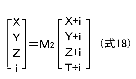

さらに、図11のフローチャートのステップS26において、飽和領域判定部1058bによる飽和画素の判定と、赤外除去するか否かの判定を行う際に、この判定処理の中に赤外分離部1053bで分離された近赤外光成分の量に基づく判定項目を追加する。
すなわち、飽和領域判定部1058bは、飽和信号レベル以上で飽和と判定された画素、または、赤外分離部1053bにおいて、(式18),(式19)によって算出された近赤外光成分量が、所定の赤外光成分量基準値を上回った画素を飽和画素と判定する。そして、以後、実施例1と同様にして、飽和画素を1、それ以外を0とする二値画像を生成し、その二値画像に対して線形補間のカーネルサイズに合わせたダイレーション(膨張)処理を行う。
これによって、赤外投光器120が照射された領域においても色ずれの発生を防止することができる。但し、ハロゲン灯の信号器のように色再現性の重要視される対象も飽和画素と判定されてしまうため、判定に用いる近赤外光成分の信号量や赤外成分量基準値は、可視光成分量で補正(正規化)してもよい。
以上、説明したように、実施例2に係る撮像装置12によれば、飽和領域判定部1058b(色飽和検出部)が、線形化出力信号RAW1が飽和信号レベル以上であるとき、または、赤外分離部1053bにおいて赤外分離色信号が生成された後で残った近赤外光成分量が赤外光成分量基準値を超えたときに飽和画素が発生したと判断して、第2色分離部1055(飽和抑制部)において、飽和が検出された赤外未分離色信号を、予め決められた所定の値に変換するクリッピング処理を行う。そして、色輝度合成部109において、クリッピング処理された赤外未分離色信号と輝度信号Y1(または輝度補正信号Y2)とを合成して映像信号(R2,G2,B2)を生成する。したがって、赤外投光器120が撮像素子102の撮像範囲に向かって近赤外光を照射しているときであっても、照射された近赤外光の反射光における偽色の発生を防止し、かつクリッピング処理によって無彩色の色ずれの発生が防止されて、近赤外光の影響を受けずに実際の色に近い色を出力することができる。
なお、実施例2は赤外投光器120を備える構成を説明したが、赤外投光器120がないときに同様の飽和判定を行ってもよい。
以上、本発明の実施例を図面により詳述したが、実施例は本発明の例示にしか過ぎないものであるため、本発明は実施例の構成にのみ限定されるものではなく、本発明の要旨を逸脱しない範囲の設計の変更等があっても、本発明に含まれることは勿論である。
本出願は、2013年2月21日に日本国特許庁に出願された特願2013-32202に基づいて優先権を主張し、その全ての開示は完全に本明細書で参照により組み込まれる。
Claims (4)
- 互いに異なる可視光領域の光を選択的に透過して、かつ近赤外光領域において、互いに等しい分光透過率を持つ3種類のフィルタと、可視光領域の分光透過率が前記3種類のフィルタの各々の分光透過率の線形和で表わされて、かつ、近赤外光領域において、前記3種類のフィルタの分光透過率と等しい分光透過率を持つ1種類のフィルタと、からなる複数のフィルタが所定のパターンで配列された複数の画素を備えて、前記複数の画素から、それぞれ、前記画素に入射する入射光の輝度に応じて非線形に変化する第1の出力信号を出力する撮像素子と、
前記撮像素子が入射光の輝度範囲に亘って線形に変化する第2の出力信号を出力すると仮定したときに、前記複数の画素から出力される複数の前記第1の出力信号を、それぞれ、前記第2の出力信号に変換する出力信号線形変換部と、
前記第2の出力信号から、前記複数のフィルタのうち前記複数の画素にそれぞれ配列されたフィルタ以外のフィルタを配列したと仮定したときに前記複数の画素からそれぞれ出力されると予測される複数の色信号を生成する色信号生成部と、
前記複数の色信号の中から、近赤外光成分が分離された複数の赤外分離色信号を生成する赤外分離部と、
前記第1の出力信号から輝度信号を生成する輝度信号生成部と、
前記複数の赤外分離色信号と前記輝度信号とを合成して映像信号を生成する色輝度合成部と、を有することを特徴とする撮像装置。 - 前記色信号が飽和していることを検出する色飽和検出部と、
飽和が検出された色信号を、予め決められた所定の値に変換するクリッピング処理を行って赤外未分離色信号を出力する飽和抑制部と、を有し、
前記色飽和検出部において、飽和している色信号が検出されたときには、前記色輝度合成部において、前記赤外未分離色信号と前記輝度信号とを合成して前記映像信号を生成して、
前記色飽和検出部において、飽和している色信号が検出されないときには、前記色輝度合成部において、前記赤外分離部から出力される赤外分離色信号と前記輝度信号とを合成して前記映像信号を生成することを特徴とする請求項1に記載の撮像装置。 - 前記赤外分離部は、さらに、赤外分離色信号が生成された後に残る近赤外光成分量を算出して、
前記飽和抑制部は、前記色飽和検出部の出力、または、前記近赤外光成分量に基づいて飽和画素の発生を判断して、飽和画素が検出されたときに、前記飽和画素の画素値を予め決められた所定の値に変換するクリッピング処理を行って赤外未分離色信号を出力して、
前記色輝度合成部において、前記赤外未分離色信号と前記輝度信号とを合成して前記映像信号を生成することを特徴とする請求項2に記載の撮像装置。 - 前記色輝度合成部は、前記赤外分離色信号を前記赤外分離色信号から算出された輝度成分によって正規化した正規化色信号、または前記赤外未分離色信号を前記赤外未分離色信号から算出された輝度成分によって正規化した正規化色信号と、前記輝度信号と、を乗算することによって合成して前記映像信号を生成することを特徴とする請求項2または請求項3に記載の撮像装置。
Priority Applications (2)
| Application Number | Priority Date | Filing Date | Title |
|---|---|---|---|
| EP14754831.7A EP2866445B1 (en) | 2013-02-21 | 2014-02-07 | Imaging device |
| US14/414,530 US9906766B2 (en) | 2013-02-21 | 2014-02-07 | Imaging device |
Applications Claiming Priority (2)
| Application Number | Priority Date | Filing Date | Title |
|---|---|---|---|
| JP2013032202A JP6231284B2 (ja) | 2013-02-21 | 2013-02-21 | 撮像装置 |
| JP2013-032202 | 2013-02-21 |
Publications (1)
| Publication Number | Publication Date |
|---|---|
| WO2014129319A1 true WO2014129319A1 (ja) | 2014-08-28 |
Family
ID=51391115
Family Applications (1)
| Application Number | Title | Priority Date | Filing Date |
|---|---|---|---|
| PCT/JP2014/052848 Ceased WO2014129319A1 (ja) | 2013-02-21 | 2014-02-07 | 撮像装置 |
Country Status (4)
| Country | Link |
|---|---|
| US (1) | US9906766B2 (ja) |
| EP (1) | EP2866445B1 (ja) |
| JP (1) | JP6231284B2 (ja) |
| WO (1) | WO2014129319A1 (ja) |
Cited By (1)
| Publication number | Priority date | Publication date | Assignee | Title |
|---|---|---|---|---|
| US10298856B2 (en) | 2015-08-27 | 2019-05-21 | Clarion Co. Ltd. | Imaging device |
Families Citing this family (21)
| Publication number | Priority date | Publication date | Assignee | Title |
|---|---|---|---|---|
| US10046716B2 (en) | 2011-02-10 | 2018-08-14 | Denso Corporation | In-vehicle camera and vehicle control system |
| JP6176028B2 (ja) * | 2013-09-26 | 2017-08-09 | 株式会社デンソー | 車両制御システム、画像センサ |
| US9690997B2 (en) | 2011-06-06 | 2017-06-27 | Denso Corporation | Recognition object detecting apparatus |
| JP6299180B2 (ja) * | 2013-11-27 | 2018-03-28 | 株式会社リコー | 撮像装置、撮像システムおよび当該撮像装置による撮像方法 |
| JP6324090B2 (ja) * | 2014-01-31 | 2018-05-16 | 株式会社 日立産業制御ソリューションズ | 撮像装置 |
| WO2015198127A1 (ja) * | 2014-06-24 | 2015-12-30 | 日立マクセル株式会社 | 撮像処理装置および撮像処理方法 |
| JP2017118296A (ja) * | 2015-12-24 | 2017-06-29 | キヤノン株式会社 | 撮像装置、画像処理装置、画像処理方法、画像処理プログラム、および、記憶媒体 |
| WO2017149932A1 (ja) * | 2016-03-03 | 2017-09-08 | ソニー株式会社 | 医療用画像処理装置、システム、方法及びプログラム |
| CN106375740B (zh) * | 2016-09-28 | 2018-02-06 | 华为技术有限公司 | 生成rgb图像的方法、装置和系统 |
| KR101923957B1 (ko) | 2017-04-21 | 2018-11-30 | 주식회사 아이닉스 | 감도 개선을 위한 영상 처리 장치 및 방법 |
| CN109474770B (zh) * | 2017-09-07 | 2021-09-14 | 华为技术有限公司 | 一种成像装置及成像方法 |
| JP7121538B2 (ja) * | 2018-05-22 | 2022-08-18 | フォルシアクラリオン・エレクトロニクス株式会社 | 撮像装置及び撮像方法 |
| US10958830B2 (en) | 2018-05-24 | 2021-03-23 | Magna Electronics Inc. | Vehicle vision system with infrared LED synchronization |
| JP7508195B2 (ja) | 2018-10-29 | 2024-07-01 | 三星電子株式会社 | 画像処理装置、撮像装置、画像処理方法及び画像処理プログラム |
| JP7265114B2 (ja) * | 2018-11-14 | 2023-04-26 | 日本電信電話株式会社 | 予測画像取得装置、原信号取得装置、予測画像取得方法及びプログラム |
| JP2021087108A (ja) * | 2019-11-28 | 2021-06-03 | ソニーセミコンダクタソリューションズ株式会社 | 固体撮像素子、撮像システム、および、固体撮像素子の制御方法 |
| JP7039639B2 (ja) | 2020-03-10 | 2022-03-22 | キヤノン株式会社 | 画像処理装置、撮像装置、および画像処理方法 |
| JP2023131002A (ja) * | 2022-03-08 | 2023-09-21 | キヤノン株式会社 | 車載カメラシステム、車載カメラシステム制御方法、及び情報処理装置 |
| US12464258B2 (en) * | 2022-09-08 | 2025-11-04 | Qualcomm Auto Ltd. | Image sensor with red-clear-clear-green (RCCG) color filter array (CFA) for vehicle sensing applications |
| JPWO2024135722A1 (ja) * | 2022-12-21 | 2024-06-27 | ||
| CN119247367B (zh) * | 2024-12-09 | 2025-03-18 | 南京信息工程大学 | 一种基于体积雷达数据的3d卷积神经网络雷暴识别方法及系统 |
Citations (7)
| Publication number | Priority date | Publication date | Assignee | Title |
|---|---|---|---|---|
| JP2001086402A (ja) | 1999-09-09 | 2001-03-30 | Nec Corp | 高ダイナミックレンジ画像処理装置および方法 |
| US20070145273A1 (en) | 2005-12-22 | 2007-06-28 | Chang Edward T | High-sensitivity infrared color camera |
| JP2008219140A (ja) * | 2007-02-28 | 2008-09-18 | Sanyo Electric Co Ltd | 撮像装置 |
| WO2009057478A1 (ja) * | 2007-11-01 | 2009-05-07 | Konica Minolta Opto, Inc. | 画像処理装置、画像処理方法、及び撮像装置 |
| JP4386096B2 (ja) | 2007-05-18 | 2009-12-16 | ソニー株式会社 | 画像入力処理装置、および、その方法 |
| JP4407448B2 (ja) | 2004-09-24 | 2010-02-03 | 三菱電機株式会社 | 撮像装置 |
| JP2011259060A (ja) * | 2010-06-07 | 2011-12-22 | Konica Minolta Opto Inc | 撮像装置 |
Family Cites Families (31)
| Publication number | Priority date | Publication date | Assignee | Title |
|---|---|---|---|---|
| CA1215169A (en) * | 1983-07-21 | 1986-12-09 | Shintaro Nakagaki | Color television camera with two or more solid-state imaging devices arranged in phase difference fashion |
| DE19616440A1 (de) * | 1996-04-25 | 1997-10-30 | Eastman Kodak Co | Verfahren und Vorrichtung zur Gewinnung eines vollen Farbbildes oder Multispektralbildes aus Bilddaten eines CCD-Bildsensors mit Mosaik-Farbfilter |
| JP3704238B2 (ja) | 1997-03-31 | 2005-10-12 | 株式会社リコー | 撮像装置 |
| US6992718B1 (en) * | 1998-08-31 | 2006-01-31 | Matsushita Electric Industrial Co., Ltd. | Illuminating apparatus, display panel, view finder, video display apparatus, and video camera mounting the elements |
| JP4142340B2 (ja) * | 2002-05-22 | 2008-09-03 | オリンパス株式会社 | 撮像装置 |
| JP4285948B2 (ja) * | 2002-06-18 | 2009-06-24 | オリンパス株式会社 | 撮像装置 |
| US7920908B2 (en) * | 2003-10-16 | 2011-04-05 | David Hattery | Multispectral imaging for quantitative contrast of functional and structural features of layers inside optically dense media such as tissue |
| GB2430105B (en) | 2004-04-05 | 2009-09-23 | Mitsubishi Electric Corp | Imaging device |
| US20060097978A1 (en) * | 2004-10-22 | 2006-05-11 | Ng Kee Y | Field-sequential color display with feedback control |
| US7194146B2 (en) * | 2004-12-22 | 2007-03-20 | Slooh, Llc | Automated system and method for processing of astronomical images |
| JP4786910B2 (ja) * | 2005-02-07 | 2011-10-05 | Hoya株式会社 | 電子内視鏡 |
| JP4310317B2 (ja) | 2006-02-06 | 2009-08-05 | キヤノン株式会社 | 可視成分割合算出方法、およびそれを用いた光学機器 |
| JP2008283442A (ja) * | 2007-05-10 | 2008-11-20 | Olympus Corp | 撮像装置 |
| JP2008306379A (ja) * | 2007-06-06 | 2008-12-18 | Toshiba Corp | 固体撮像素子 |
| KR101441432B1 (ko) | 2008-02-11 | 2014-09-17 | 삼성전자주식회사 | 이미지 센서 |
| US9117133B2 (en) * | 2008-06-18 | 2015-08-25 | Spectral Image, Inc. | Systems and methods for hyperspectral imaging |
| JP5366619B2 (ja) * | 2008-08-12 | 2013-12-11 | キヤノン株式会社 | 画像処理装置、撮像装置、画像処理方法、画像処理プログラム |
| KR101534547B1 (ko) * | 2008-11-24 | 2015-07-08 | 삼성전자주식회사 | 이미지 센서 및 이를 포함하는 시스템 |
| US8274565B2 (en) * | 2008-12-31 | 2012-09-25 | Iscon Video Imaging, Inc. | Systems and methods for concealed object detection |
| CN103561193B (zh) * | 2009-01-19 | 2016-06-15 | 杜比实验室特许公司 | 自动化方法以及自动化的图像处理系统 |
| DE102009001122B8 (de) * | 2009-02-24 | 2020-11-26 | Robert Bosch Gmbh | Kameraanordnung und Verfahren zum Ermitteln von Bildsignalen mit Farbwerten |
| JP2010206678A (ja) * | 2009-03-05 | 2010-09-16 | Panasonic Corp | 固体撮像装置、撮像モジュール、及び撮像システム |
| TWI650848B (zh) * | 2009-08-07 | 2019-02-11 | 日商半導體能源研究所股份有限公司 | 半導體裝置和其製造方法 |
| WO2011027664A1 (en) * | 2009-09-04 | 2011-03-10 | Semiconductor Energy Laboratory Co., Ltd. | Liquid crystal display device and method for manufacturing the same |
| US8619143B2 (en) * | 2010-03-19 | 2013-12-31 | Pixim, Inc. | Image sensor including color and infrared pixels |
| WO2011155136A1 (ja) * | 2010-06-07 | 2011-12-15 | コニカミノルタオプト株式会社 | 撮像装置 |
| JP5406151B2 (ja) * | 2010-09-24 | 2014-02-05 | パナソニック株式会社 | 3次元撮像装置 |
| JP5231511B2 (ja) * | 2010-11-09 | 2013-07-10 | 富士フイルム株式会社 | 内視鏡診断装置 |
| JP5159904B2 (ja) * | 2011-01-11 | 2013-03-13 | 富士フイルム株式会社 | 内視鏡診断装置 |
| CN102625043B (zh) * | 2011-01-25 | 2014-12-10 | 佳能株式会社 | 图像处理设备、成像设备和图像处理方法 |
| JP2012252091A (ja) * | 2011-06-01 | 2012-12-20 | Sony Corp | 表示装置 |
-
2013
- 2013-02-21 JP JP2013032202A patent/JP6231284B2/ja not_active Expired - Fee Related
-
2014
- 2014-02-07 EP EP14754831.7A patent/EP2866445B1/en active Active
- 2014-02-07 US US14/414,530 patent/US9906766B2/en not_active Expired - Fee Related
- 2014-02-07 WO PCT/JP2014/052848 patent/WO2014129319A1/ja not_active Ceased
Patent Citations (7)
| Publication number | Priority date | Publication date | Assignee | Title |
|---|---|---|---|---|
| JP2001086402A (ja) | 1999-09-09 | 2001-03-30 | Nec Corp | 高ダイナミックレンジ画像処理装置および方法 |
| JP4407448B2 (ja) | 2004-09-24 | 2010-02-03 | 三菱電機株式会社 | 撮像装置 |
| US20070145273A1 (en) | 2005-12-22 | 2007-06-28 | Chang Edward T | High-sensitivity infrared color camera |
| JP2008219140A (ja) * | 2007-02-28 | 2008-09-18 | Sanyo Electric Co Ltd | 撮像装置 |
| JP4386096B2 (ja) | 2007-05-18 | 2009-12-16 | ソニー株式会社 | 画像入力処理装置、および、その方法 |
| WO2009057478A1 (ja) * | 2007-11-01 | 2009-05-07 | Konica Minolta Opto, Inc. | 画像処理装置、画像処理方法、及び撮像装置 |
| JP2011259060A (ja) * | 2010-06-07 | 2011-12-22 | Konica Minolta Opto Inc | 撮像装置 |
Non-Patent Citations (1)
| Title |
|---|
| See also references of EP2866445A4 |
Cited By (1)
| Publication number | Priority date | Publication date | Assignee | Title |
|---|---|---|---|---|
| US10298856B2 (en) | 2015-08-27 | 2019-05-21 | Clarion Co. Ltd. | Imaging device |
Also Published As
| Publication number | Publication date |
|---|---|
| EP2866445B1 (en) | 2021-06-16 |
| US9906766B2 (en) | 2018-02-27 |
| JP6231284B2 (ja) | 2017-11-15 |
| US20150172618A1 (en) | 2015-06-18 |
| EP2866445A1 (en) | 2015-04-29 |
| EP2866445A4 (en) | 2016-04-13 |
| JP2014165528A (ja) | 2014-09-08 |
Similar Documents
| Publication | Publication Date | Title |
|---|---|---|
| JP6231284B2 (ja) | 撮像装置 | |
| JP6441771B2 (ja) | 撮像装置 | |
| KR101747603B1 (ko) | 컬러 나이트 비전 시스템 및 그 동작 방법 | |
| JP6029954B2 (ja) | 撮像装置 | |
| JP5308375B2 (ja) | 信号処理装置、固体撮像装置、電子情報機器、信号処理方法、制御プログラムおよび記録媒体 | |
| US9131199B2 (en) | Imaging apparatus capable of generating an appropriate color image | |
| JP6000133B2 (ja) | 撮像装置、撮像システム及び撮像方法 | |
| JP4250506B2 (ja) | 画像処理方法、画像処理装置、画像処理プログラムおよび撮像システム | |
| JP5228717B2 (ja) | 画像入力装置 | |
| US10326947B2 (en) | Image processing device, imaging device, image processing method, and program | |
| JP5159715B2 (ja) | 画像処理装置 | |
| JP2012010282A (ja) | 撮像装置、露光制御方法及び露光制御プログラム | |
| JP5545596B2 (ja) | 画像入力装置 | |
| JP6717660B2 (ja) | 撮像装置 | |
| JP2010171950A (ja) | 撮像装置および撮像装置の色補正方法 | |
| JP2012010141A (ja) | 画像処理装置 | |
| JP7121538B2 (ja) | 撮像装置及び撮像方法 | |
| JP5182518B2 (ja) | 撮像装置および撮像方法 | |
| JP6504892B2 (ja) | 撮像装置 | |
| JP2012015834A (ja) | 撮像装置 | |
| KR100999885B1 (ko) | 이미지 신호 처리 장치, 이미지 신호 처리 장치의 색 노이즈 저감 방법 및 색 노이즈 저감 방법이 기록된 기록 매체 | |
| JP5920144B2 (ja) | 撮像装置および撮像方法 |
Legal Events
| Date | Code | Title | Description |
|---|---|---|---|
| 121 | Ep: the epo has been informed by wipo that ep was designated in this application |
Ref document number: 14754831 Country of ref document: EP Kind code of ref document: A1 |
|
| WWE | Wipo information: entry into national phase |
Ref document number: 14414530 Country of ref document: US |
|
| NENP | Non-entry into the national phase |
Ref country code: DE |