WO2014129340A1 - 逆浸透膜装置及びその運転方法 - Google Patents
逆浸透膜装置及びその運転方法 Download PDFInfo
- Publication number
- WO2014129340A1 WO2014129340A1 PCT/JP2014/053008 JP2014053008W WO2014129340A1 WO 2014129340 A1 WO2014129340 A1 WO 2014129340A1 JP 2014053008 W JP2014053008 W JP 2014053008W WO 2014129340 A1 WO2014129340 A1 WO 2014129340A1
- Authority
- WO
- WIPO (PCT)
- Prior art keywords
- reverse osmosis
- osmosis membrane
- water
- membrane element
- pressure
- Prior art date
- Legal status (The legal status is an assumption and is not a legal conclusion. Google has not performed a legal analysis and makes no representation as to the accuracy of the status listed.)
- Ceased
Links
Images


Classifications
-
- C—CHEMISTRY; METALLURGY
- C02—TREATMENT OF WATER, WASTE WATER, SEWAGE, OR SLUDGE
- C02F—TREATMENT OF WATER, WASTE WATER, SEWAGE, OR SLUDGE
- C02F1/00—Treatment of water, waste water, or sewage
- C02F1/44—Treatment of water, waste water, or sewage by dialysis, osmosis or reverse osmosis
- C02F1/441—Treatment of water, waste water, or sewage by dialysis, osmosis or reverse osmosis by reverse osmosis
-
- B—PERFORMING OPERATIONS; TRANSPORTING
- B01—PHYSICAL OR CHEMICAL PROCESSES OR APPARATUS IN GENERAL
- B01D—SEPARATION
- B01D61/00—Processes of separation using semi-permeable membranes, e.g. dialysis, osmosis or ultrafiltration; Apparatus, accessories or auxiliary operations specially adapted therefor
- B01D61/02—Reverse osmosis; Hyperfiltration ; Nanofiltration
- B01D61/025—Reverse osmosis; Hyperfiltration
-
- B—PERFORMING OPERATIONS; TRANSPORTING
- B01—PHYSICAL OR CHEMICAL PROCESSES OR APPARATUS IN GENERAL
- B01D—SEPARATION
- B01D65/00—Accessories or auxiliary operations, in general, for separation processes or apparatus using semi-permeable membranes
- B01D65/02—Membrane cleaning or sterilisation ; Membrane regeneration
-
- B—PERFORMING OPERATIONS; TRANSPORTING
- B01—PHYSICAL OR CHEMICAL PROCESSES OR APPARATUS IN GENERAL
- B01D—SEPARATION
- B01D2317/00—Membrane module arrangements within a plant or an apparatus
- B01D2317/06—Use of membrane modules of the same kind
-
- B—PERFORMING OPERATIONS; TRANSPORTING
- B01—PHYSICAL OR CHEMICAL PROCESSES OR APPARATUS IN GENERAL
- B01D—SEPARATION
- B01D2319/00—Membrane assemblies within one housing
- B01D2319/02—Elements in series
- B01D2319/025—Permeate series
-
- B—PERFORMING OPERATIONS; TRANSPORTING
- B01—PHYSICAL OR CHEMICAL PROCESSES OR APPARATUS IN GENERAL
- B01D—SEPARATION
- B01D2321/00—Details relating to membrane cleaning, regeneration, sterilization or to the prevention of fouling
- B01D2321/04—Backflushing
-
- B—PERFORMING OPERATIONS; TRANSPORTING
- B01—PHYSICAL OR CHEMICAL PROCESSES OR APPARATUS IN GENERAL
- B01D—SEPARATION
- B01D2321/00—Details relating to membrane cleaning, regeneration, sterilization or to the prevention of fouling
- B01D2321/40—Automatic control of cleaning processes
-
- C—CHEMISTRY; METALLURGY
- C02—TREATMENT OF WATER, WASTE WATER, SEWAGE, OR SLUDGE
- C02F—TREATMENT OF WATER, WASTE WATER, SEWAGE, OR SLUDGE
- C02F2103/00—Nature of the water, waste water, sewage or sludge to be treated
- C02F2103/007—Contaminated open waterways, rivers, lakes or ponds
-
- C—CHEMISTRY; METALLURGY
- C02—TREATMENT OF WATER, WASTE WATER, SEWAGE, OR SLUDGE
- C02F—TREATMENT OF WATER, WASTE WATER, SEWAGE, OR SLUDGE
- C02F2103/00—Nature of the water, waste water, sewage or sludge to be treated
- C02F2103/08—Seawater, e.g. for desalination
-
- C—CHEMISTRY; METALLURGY
- C02—TREATMENT OF WATER, WASTE WATER, SEWAGE, OR SLUDGE
- C02F—TREATMENT OF WATER, WASTE WATER, SEWAGE, OR SLUDGE
- C02F2209/00—Controlling or monitoring parameters in water treatment
- C02F2209/005—Processes using a programmable logic controller [PLC]
-
- C—CHEMISTRY; METALLURGY
- C02—TREATMENT OF WATER, WASTE WATER, SEWAGE, OR SLUDGE
- C02F—TREATMENT OF WATER, WASTE WATER, SEWAGE, OR SLUDGE
- C02F2209/00—Controlling or monitoring parameters in water treatment
- C02F2209/03—Pressure
-
- C—CHEMISTRY; METALLURGY
- C02—TREATMENT OF WATER, WASTE WATER, SEWAGE, OR SLUDGE
- C02F—TREATMENT OF WATER, WASTE WATER, SEWAGE, OR SLUDGE
- C02F2303/00—Specific treatment goals
- C02F2303/16—Regeneration of sorbents, filters
-
- Y—GENERAL TAGGING OF NEW TECHNOLOGICAL DEVELOPMENTS; GENERAL TAGGING OF CROSS-SECTIONAL TECHNOLOGIES SPANNING OVER SEVERAL SECTIONS OF THE IPC; TECHNICAL SUBJECTS COVERED BY FORMER USPC CROSS-REFERENCE ART COLLECTIONS [XRACs] AND DIGESTS
- Y02—TECHNOLOGIES OR APPLICATIONS FOR MITIGATION OR ADAPTATION AGAINST CLIMATE CHANGE
- Y02A—TECHNOLOGIES FOR ADAPTATION TO CLIMATE CHANGE
- Y02A20/00—Water conservation; Efficient water supply; Efficient water use
- Y02A20/124—Water desalination
- Y02A20/131—Reverse-osmosis
Definitions
- the present invention relates to a reverse osmosis membrane device and a method for operating the reverse osmosis membrane device that can reduce the labor and time required for cleaning and replacement of the reverse osmosis membrane and enable stable continuous operation.
- a reverse osmosis membrane device equipped with a reverse osmosis membrane module is used to generate fresh water from seawater and clean water from rivers and lakes.
- a reverse osmosis membrane device usually performs pretreatment by taking raw seawater, rivers, lake water, etc., and then disinfecting it with a bactericidal agent, removing impurities with a sand filter, etc.
- generated by performing is used.
- the treated water is supplied to the reverse osmosis membrane module with a high pressure pump at a high pressure of, for example, about 6.0 MPa, and the reverse osmosis membrane module allows the reverse osmosis membrane to permeate the reverse osmosis membrane so as to obtain permeated water as production water. I have to.
- the reverse osmosis membrane module is usually composed of a plurality of reverse osmosis membrane elements.
- the reverse osmosis membrane element is formed by winding a bag-like reverse osmosis membrane containing a flow path material around a center pipe where permeate is collected in a spiral shape through a mesh spacer.
- a spiral type with a structure in which a brine seal is provided at one end.
- a flat membrane type in which a plurality of flat sheet-like reverse osmosis membranes are overlapped.
- a reverse osmosis membrane module a plurality of reverse osmosis membrane elements are usually arranged in series in a single high-pressure vessel, and the water to be treated (clarified water) is passed through from the reverse osmosis membrane element on the upstream side in order.
- the membrane is separated into concentrated water containing salt and impurities, and permeated water is obtained from each reverse osmosis membrane element.
- the concentrated water separated from the permeated water by each reverse osmosis membrane element is further membrane-separated into the permeated water and the concentrated water by the downstream reverse osmosis membrane element. Therefore, the salinity concentration and the impurity concentration of the concentrated water increase toward the downstream side.
- Patent Document 2 discloses a configuration in which a plurality of high-pressure vessels containing spiral reverse osmosis membrane elements are arranged in parallel with respect to the introduction path of water to be treated.
- FIG. 6 shows a configuration example of a conventional reverse osmosis membrane device in which a plurality of spiral type reverse osmosis membrane elements are arranged in series inside one high-pressure vessel.
- this reverse osmosis membrane device 100 has 4 to 6 reverse osmosis membrane elements 104 arranged in series in one high-pressure vessel 102.
- the treated water tw is supplied at a high pressure from the treated water introduction path 114 to the inlet opening 102a of the high-pressure vessel 102.
- the treated water tw enters from the inlet end of the reverse osmosis membrane element 104 in the foremost stage
- the reverse osmosis membrane element 104a is separated into permeated water pw and concentrated water cs by the reverse osmosis membrane.
- the permeated water pw flows into the center pipe 106, and the concentrated water cs flows out from the outlet end of the reverse osmosis membrane element in the foremost stage.
- the inlet end of the center pipe 106 of the foremost reverse osmosis membrane element 104 a is closed with an end cap 108.
- the center pipe 106 of each reverse osmosis membrane element 104 is connected by a connector 110. Therefore, the permeated water pw of each reverse osmosis membrane element joins at the center pipe 106 and is discharged from the outlet opening 102 b of the high-pressure vessel 102 to the permeated water outflow path 116.
- each reverse osmosis membrane element 104 Since the inside of the high-pressure vessel 102 is partitioned by a brine seal 112 provided on the outer peripheral surface of each reverse osmosis membrane element 104, the concentrated water cw flowing out from the upstream reverse osmosis membrane element is Without passing through, it flows into the reverse osmosis membrane element at the latter stage as treated water. Thus, the concentrated water cw is sequentially permeated through each reverse osmosis membrane element. The concentrated water cw discharged from the reverse osmosis membrane element 104 arranged at the final stage is discharged to the concentrated water discharge path 118 from the outlet opening 102 c formed at the outlet end of the high-pressure vessel 102.
- a differential pressure gauge 120 for detecting a differential pressure between the pressure of the treated water tw flowing through the treated water introduction path 114 and the pressure of the concentrated water cw flowing through the concentrated water discharge path 118 is provided.
- the detection value of the differential pressure gauge 120 exceeds a threshold value, the reverse osmosis membrane element 100 is washed by a fouling substance deposited on the reverse osmosis membrane, such as a poorly soluble component, a polymer solute, a colloid, or a micro solid matter. It was judged that the amount of deposition exceeded the limit value, the operation of the reverse osmosis membrane device 100 was stopped, and the cleaning operation was performed.
- the deposition of the fouling substance on the reverse osmosis membrane concentrates on the reverse osmosis membrane element arranged in the previous stage among the reverse osmosis membrane elements arranged in series.
- the concentration of metal ions such as Ca and Mg in the concentrated seawater increases as the reverse osmosis membrane element in the latter stage. Since these metal ions react with CO 2 or the like melted in seawater to generate scale, the amount of scale deposited on the reverse osmosis membrane increases in the reverse osmosis membrane element at the subsequent stage.
- a chemical such as citric acid or HCl
- the conventional cleaning method simultaneously cleans a plurality of reverse osmosis membrane elements arranged in series in a single high-pressure vessel, so that the reverse osmosis membrane element in the middle part with less fouling (clogging) can be obtained.
- cleaning is performed more than necessary, and cleaning time and cleaning chemicals are wasted.
- the reverse osmosis membrane is inevitably damaged by the cleaning, and the reverse osmosis membrane is unnecessarily damaged.
- the differential pressure gauge monitors the accumulated differential pressure of a plurality of reverse osmosis membrane elements, the sensitivity for detecting the differential pressure is low, and thus the cleaning timing may be lost.
- a plurality of reverse osmosis membrane elements are arranged in series inside a high-pressure vessel, and water to be treated (clarified water) generated by pretreatment of raw water is reversed in the first stage.
- a reverse osmosis membrane device that separates membranes into concentrated water and permeate from the osmosis membrane element in order to obtain permeated water.
- the reverse osmosis membrane device reduces the labor and time required for cleaning the reverse osmosis membrane device. The purpose is to increase the operation rate of the system and enable stable operation.
- the reverse osmosis membrane device of the present invention is arranged in parallel with the introduction path of the water to be treated, and among the plurality of reverse osmosis membrane elements arranged in series, the front stage where the fouling is severe (
- a plurality of first high-pressure vessel groups each incorporating a first reverse osmosis membrane element in the upstream (downstream with respect to the treated water) or downstream (downstream with respect to the treated water), and a plurality of reverse osmosis membrane elements
- a second high-pressure vessel that is arranged in series with respect to the first high-pressure vessel group and in which a second reverse osmosis membrane element other than the first reverse osmosis membrane element is incorporated in a series arrangement,
- a deposition amount detecting means for detecting a deposition amount of the fouling material deposited on the reverse osmosis membrane of the reverse osmosis membrane element; and a first reverse when the fouling material deposited on the first reverse osmosis membrane element exceeds
- the first reverse osmosis membrane element in the front stage or the rear stage where fouling is severe is accommodated in a high-pressure vessel separate from other reverse osmosis membrane elements. . Then, the amount of fouling material deposited only on the first reverse osmosis membrane element is detected, and when this amount of deposition exceeds the threshold, only the first reverse osmosis membrane element is cleaned or replaced. Since the second reverse osmosis membrane element is not frequently washed or exchanged, it may be separately washed or exchanged as necessary.
- the first high-pressure vessel groups each containing only the front-stage or rear-stage reverse osmosis membrane elements each having severe fouling are arranged in parallel, one reverse osmosis membrane element can be maintained for cleaning or replacement. Even if the operation is stopped by inspection, the operation can be continued by supplying the water to be treated to the reverse osmosis membrane element incorporated in the other first high-pressure vessel.
- the timing of cleaning or replacement for the upstream or downstream reverse osmosis membrane element independently of the second reverse osmosis membrane element, it is possible to eliminate waste of the cleaning chemical and reduce the cost.
- a cleaning liquid supply unit that supplies a cleaning liquid to the reverse osmosis membrane of the first reverse osmosis membrane element, and a cleaning liquid discharge that discharges the cleaning liquid after cleaning the reverse osmosis membrane of the first reverse osmosis membrane element And a road.
- the cleaning liquid is supplied to the reverse osmosis membrane, and the fouling substance attached to the reverse osmosis membrane can be peeled by the peeling force that acts on the reverse osmosis membrane. Therefore, it is not necessary to rely on the cleaning ability of chemicals having a strong cleaning effect such as acid and alkali, and cleaning with a small environmental load is possible.
- a cleaning liquid flow that contacts the reverse osmosis membrane along the reverse osmosis membrane may be formed, or a flow that passes through the reverse osmosis membrane may be formed by the cleaning liquid flow.
- the flow of the cleaning liquid along the reverse osmosis membrane can be formed by the flow of the cleaning liquid flowing between the treated water introduction path and the concentrated water discharge path, and the flow of the cleaning liquid that permeates the reverse osmosis membrane is, for example, from the permeation water path to the reverse osmosis membrane.
- a differential pressure for detecting a differential pressure between the pressure of the water to be treated flowing through the treated water introduction path of the first reverse osmosis membrane element and the pressure of the concentrated water flowing through the concentrated water discharge path
- a detection means and a deposition amount calculation means for calculating a deposition amount of the fouling substance from a detection value of the differential pressure detection means can be provided.
- an alarm transmitter may be further provided that issues an alarm when the deposition amount of the fouling substance detected by the deposition amount detection means exceeds a threshold value. This makes it possible to know without delay the timing at which the first reverse osmosis membrane element needs to be washed or replaced.
- a plurality of second high-pressure vessels can be arranged in parallel with respect to the concentrated water outflow passage provided at the outlet of the first high-pressure vessel group.
- the introduction of water to be treated is stopped for the first reverse osmosis membrane element in which the fouling substance exceeds the threshold
- the channel switching means introduces the water to be treated into the other first reverse osmosis membrane element
- the cleaning liquid is supplied from the cleaning water supply unit, and the flow of the cleaning liquid causes the first reverse osmosis membrane element to After the fouling material adhering to the reverse osmosis membrane is peeled off, the cleaning step is to discharge the cleaning liquid from the cleaning water discharge passage.
- the timing at which the first reverse osmosis membrane element needs to be cleaned can be known without delay from the alarm signal.
- the water to be treated is supplied to the first reverse osmosis membrane element at a pressure lower than the osmotic pressure generated in the reverse osmosis membrane of the first reverse osmosis membrane element via the permeation channel.
- the first reverse osmosis membrane element with severe fouling is built in one high-pressure vessel, and a plurality of the high-pressure vessels are arranged in parallel with the introduction path of the water to be treated. It reduces the labor and time required for cleaning the reverse osmosis membrane device, increases the operation rate of the reverse osmosis membrane device, and enables stable operation.
- FIG. 1 is a system diagram of a reverse osmosis membrane device according to a first embodiment of the present invention. It is a block diagram which shows the control system of the reverse osmosis membrane apparatus which concerns on the said 1st Embodiment. It is a systematic diagram of the reverse osmosis membrane apparatus which concerns on 2nd Embodiment of this invention. It is a systematic diagram of the reverse osmosis membrane apparatus which concerns on 3rd Embodiment of this invention. It is a systematic diagram of the reverse osmosis membrane apparatus which concerns on 4th Embodiment of this invention. It is a longitudinal cross-sectional view of the conventional reverse osmosis membrane apparatus.
- FIG. 1 A first embodiment of the present invention will be described with reference to FIG.
- This embodiment is an example of a reverse osmosis membrane device applied to a seawater desalination plant.
- pretreatment is performed to sterilize the introduced raw seawater and remove relatively large contaminants such as garbage and microorganisms as water to be treated.
- the clear seawater sw after the pretreatment is used as the water to be treated.
- the reverse osmosis membrane device 10A two high-pressure vessels 12a and 12b are connected to the introduction path 18 of the clear seawater sw via the introduction branch paths 18a and 18b.
- One reverse osmosis membrane element 14a and 14b is built in each of the high-pressure vessels 12a and 12b.
- the clarified seawater sw is supplied at high pressure to the inlet opening 22 of the high-pressure vessel 12a or 12b through the introduction branch path 18a or 18b by the pump 20 provided in the clarified seawater introduction path 18.
- the clarified seawater sw enters the reverse osmosis membrane element 14a or 14b from the inlet end of the reverse osmosis membrane element 14a or 14b, and is separated into the permeated water pw and the concentrated seawater cs by the reverse osmosis membrane.
- the high pressure vessels 12a and 12b may be operated simultaneously, or only one of the high pressure vessels 12a or 12b may be operated.
- the permeated water pw flows into the center pipe 28, and the concentrated seawater cs flows out from the outlet end of the reverse osmosis membrane element 14a or 14b.
- the inlet of the center pipe 28 of the reverse osmosis membrane element 14 a or 14 b is closed with an end cap 30.
- the center pipe 28 is connected to the outlet opening 24 of the high-pressure vessel 12a or 12b with a connector 32, and the permeated water pw flows from the center pipe 28 through the outlet opening 24 to the permeated water outflow passage 34a or 34b.
- the permeate outflow channels 34 a and 34 b are connected to a single permeate collecting channel 36.
- the inside of the high-pressure vessel 12a or 12b is partitioned by a brine seal 31 provided on the outer peripheral surface of the reverse osmosis membrane element 14a or 14b.
- Concentrated seawater cs flows out from the outlet end of the reverse osmosis membrane element 14a or 14b.
- An outlet opening 26 is formed at the outlet end of the high-pressure vessel 12a or 12b, and the outlet opening 26 is connected to the concentrated seawater outflow passage 38a or 38b.
- the concentrated seawater outflow paths 38 a and 38 b merge into one concentrated seawater collecting path 40, and the concentrated seawater collecting path 40 is connected to an inlet opening 16 a formed in the high-pressure vessel 16.
- the configuration of the high-pressure vessel 16 and its interior is basically the same as the configuration of the high-pressure vessel 102 and its interior shown in FIG.
- a large number of reverse osmosis membrane elements 42 are arranged in series inside the high-pressure vessel 16.
- the center pipes 44 through which the permeated water pw of each reverse osmosis membrane element flows out are connected to each other by a connector 46, and the permeated water pw of each reverse osmosis membrane element merges at the center pipe 44.
- the center pipe 44 is connected to the outlet opening 16 b of the high-pressure vessel 16 by a connector 46.
- the permeated water pw of each reverse osmosis membrane element flows out to the permeated water outflow passage 52 from the outlet opening 16b.
- the permeate collecting path 36 is connected to the permeate outflow path 52.
- the front end of the center pipe 44 of the foremost reverse osmosis membrane element 42 is closed by an end cap 48, and the inside of the high-pressure vessel 16 is partitioned by a brine seal 50 provided on the outer peripheral surface of each reverse osmosis membrane element.
- the concentrated seawater cs concentrated by the reverse osmosis membrane element 14a or 14b flows into the high-pressure vessel 16 from the concentrated seawater collecting passage 40.
- the concentrated seawater cs flowing into the high-pressure vessel 16 is first membrane-separated into the concentrated seawater cs and the permeated water pw by the reverse osmosis membrane element 42 in the forefront stage.
- the permeated water pw flows out to the center pipe 46, and the concentrated seawater cs flows out from the outlet end of the foremost reverse osmosis membrane element 42, and is then concentrated in sequence at each reverse osmosis membrane element.
- An outlet opening 16c is formed at the outlet end of the high-pressure vessel 16, and the concentrated seawater outflow passage 54 is connected to the outlet opening 16c.
- the concentrated seawater cs after membrane separation by the reverse osmosis membrane element 42 in the final stage flows out to the concentrated seawater outflow passage 54 from the outlet opening 16c.
- the high-pressure vessel 12a is provided with a differential pressure gauge 56a for detecting a pressure difference between the clear seawater sw flowing through the introduction branch passage 18a and the concentrated seawater cs flowing through the concentrated seawater outflow passage 34a, and the high-pressure vessel 12b has an introduction branch passage.
- a differential pressure gauge 56b for detecting a pressure difference between the clear seawater sw flowing through 18b and the concentrated seawater cs flowing through the concentrated seawater outflow passage 38b is provided.
- gate valves 58a, 58b, 60a and 60b for switching the flow paths are provided in the introduction branch paths 18a and 18b and the concentrated seawater outflow paths 38a and 38b, respectively.
- Cleaning liquid injection paths 62a and 62b are connected to the concentrated seawater outflow paths 38a and 38b, respectively, and cleaning liquid discharge paths 64a and 64b are connected to the introduction branch paths 18a and 18b, respectively.
- the high-pressure vessel 16 is provided with a differential pressure gauge 66 that detects a differential pressure between the concentrated seawater cs flowing through the concentrated seawater outflow passage 40 and the concentrated seawater cs flowing through the concentrated seawater outflow passage 54.
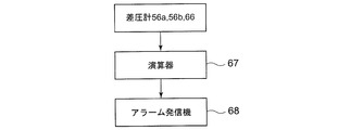
- FIG. 2 shows a control system of the reverse osmosis membrane 10A.
- the detection values of the differential pressure gauges 56a, 56b, and 66 are sent to the calculation unit 67.
- the computing unit 67 calculates the fouling material deposition amount from the input detection value. If the calculated accumulation amount exceeds the threshold value, an alarm transmission signal is sent to the alarm transmitter 68.
- the alarm transmitter 68 receives the alarm transmission signal and transmits an alarm.
- the clarified seawater sw is introduced into one or both of the high-pressure vessels 12a or 12b by operating the gate valves 58a, 58b, 60a and 60b, and one of them is maintained.
- the gate valves 58a, 58b, 60a and 60b When checking, introduce clear seawater sw to only one side.
- the permeated water pw membrane-separated by the reverse osmosis membrane element 14a or 14b built in the high-pressure vessel 12a or 12b flows out to the permeated water outflow passage 52 through the permeate outflow passage 34a or 34b and the permeate collecting passage 36.
- the concentrated seawater cs flows into the high-pressure vessel 16 via the concentrated seawater outflow passage 38a or 38b and the concentrated seawater outflow passage 40, and is sequentially concentrated from the upstream side by the reverse osmosis membrane element 42 built in the high-pressure vessel 16.
- the membrane is separated into cs and permeated water pw.
- the differential pressure gauges 56a, 56b and 66 are monitored, and when the accumulated amount of the fouling material calculated by the computing unit 67 based on the detected values of the differential pressure gauges exceeds a threshold value, the gate valves 58a, 58b, 60a and 60b. Is operated to stop the flow of the clear seawater sw through the reverse osmosis membrane element exceeding the threshold value, and the cleaning process of the reverse osmosis membrane element is started.
- the cleaning liquid a is injected from the cleaning liquid injection path 62a to form a cleaning liquid flow in contact with the reverse osmosis membrane surface of the reverse osmosis membrane element 14a.
- the cleaning liquid a after cleaning the reverse osmosis membrane is discharged from the cleaning water discharge path 64a.
- the same operation is performed when the reverse osmosis membrane element 14b is washed.
- the amount of deposition of the reverse osmosis membrane element 42 built in the high-pressure vessel 16 is small and the frequency of cleaning is low, but when the amount of deposition exceeds the threshold value, the cleaning process is similarly performed. If the fouling substance cannot be completely removed even after washing, the reverse osmosis membrane element may be replaced.
- the present embodiment since only the first reverse osmosis membrane elements 14a and 14b with severe fouling are washed, it is possible to eliminate waste of the washing agent and to reduce the cost.
- the high-pressure vessels 12a and 12b each containing the reverse osmosis membrane elements 14a and 14b having a high washing frequency are arranged in parallel to the clarified seawater introduction passage 18, when one washing step is performed, the other operation is continued. it can. Therefore, the operation rate of the reverse osmosis membrane device 10A can be maintained high, and stable operation is possible. Furthermore, since it is only necessary to open the high-pressure vessel 12a or 12b containing only the reverse osmosis membrane element 14a or 14b, it is possible to save the labor of the cleaning operation and shorten the time required for the cleaning.
- each of the high-pressure vessels 12a and 12b incorporates one reverse osmosis membrane element.
- the present invention is not necessarily limited to one reverse osmosis membrane element, and a plurality of reverse osmosis membrane elements. A membrane element may be incorporated.
- the reverse osmosis membrane device 10B of this embodiment includes a plurality of high-pressure vessels 16 containing a plurality of reverse osmosis membrane elements 42 arranged in series with respect to the concentrated seawater outflow passage 40. They are arranged in parallel.
- Each high-pressure vessel 16 and its internal structure are the same as the high-pressure vessel 16 and its internal structure of the first embodiment.
- the permeate outflow passage 70 connected to the outlet opening 16 b of each high-pressure vessel 16 merges into one permeate collecting passage 71.
- the concentrated seawater outflow path 72 connected to the outlet opening 16 c of the high-pressure vessel 16 joins the concentrated seawater collecting path 73.
- gate valves 74a and 74b are provided in the permeate outflow passages 34a and 34b through which the permeate pw flows out from the high pressure vessels 12a and 12b, respectively.
- a bypass path 76a that branches from the introduction branch path 18a upstream of the gate valve 58a and connects to the permeate outflow path 34a upstream of the gate valve 74a is provided.
- a bypass path 76b is provided which branches from the introduction branch path 18b upstream of the gate valve 58b and connects to the permeate outflow path 34b upstream of the gate valve 74b.
- Gate valves 77a and 77b are provided in the bypass passages 76a and 76b, respectively.
- the permeate outflow passages 34a and 34b are provided with clear seawater discharge passages 78a and 78b for discharging the clear seawater sw supplied as a cleaning liquid during the cleaning step.
- Other configurations are basically the same as those of the first embodiment.
- the production capacity of the permeated water pw can be increased.
- the cleaning step for example, when the reverse osmosis membrane element 14a built in the high-pressure vessel 12a is cleaned, the gate valves 58a, 74a and 60a are closed and the gate valve 77a is opened. Thereafter, the clear seawater sw is supplied from the bypass passage 76a to the permeate outflow passage 34a at a pressure lower than the osmotic pressure generated in the reverse osmosis membrane of the reverse osmosis membrane element 14a by the pump 20.
- the mixed flow in which the permeated water pw and the clear seawater sw are mixed reaches the reverse osmosis membrane of the reverse osmosis membrane element 14a, and only the permeated water pw of the mixed flow passes through the reverse osmosis membrane. Due to the pressure difference between the osmotic pressure of the clear seawater sw generated at this time and the permeated water pw having no osmotic pressure, the permeated water pw is permeated through the reverse osmosis membrane from the permeate outflow passage 34a. The fouling material deposited on the reverse osmosis membrane is peeled and removed by permeation of the permeated water pw.
- the permeated water pw that has passed through the reverse osmosis membrane due to the forward osmosis phenomenon is discharged from the washing water discharge path 64a, and the clear seawater sw supplied to the reverse osmosis membrane element 14a is discharged from the clear seawater discharge path 78a.
- the same operation is performed when the reverse osmosis membrane element 14b built in the high-pressure vessel 12b is washed. If the fouling substance cannot be removed by washing the reverse osmosis membrane element, the reverse osmosis membrane element may be replaced.
- the pump 20 can be operated with low power. .
- cleaning can be performed without using a chemical having a strong cleaning effect as a cleaning solution, and energy-saving cleaning with a low environmental load can be realized.
- the reverse osmosis membrane device 10C of this embodiment has the same configuration as the high-pressure vessel 16 and its internal structure shown in FIG. 1 or FIG. 3, and the high-pressure vessel 16 in which a plurality of reverse osmosis membrane elements 42 are arranged in series.
- the clear seawater introduction path 18 is connected to the inlet end of the high-pressure vessel 16, and the concentrated seawater outflow passage 54 connected to the outlet opening 16c of the high-pressure vessel 16 branches into the branch outflow passages 80a and 80b.
- the branch outlet 80b is connected to the inlet opening of the high-pressure container 81b.
- the high-pressure vessels 81a and 81b and the internal structure thereof are the same as the internal structures of the high-pressure vessels 12a and 12b of the first embodiment and the second embodiment.
- One reverse osmosis membrane element 85a is built in the high-pressure vessel 81a, and one reverse osmosis membrane element 85b is built in the high-pressure vessel 81b.
- the permeated water pw membrane-separated by the reverse osmosis membrane elements 85a and 85b flows out from the permeated water outflow paths 86a and 86b to the permeated water collecting path 88, respectively.
- the concentrated seawater cs flows out from the outlet opening 84 to the concentrated seawater outflow paths 90 a and 90 b and joins the concentrated seawater collecting path 91.
- a differential pressure gauge 92a for detecting a differential pressure between the concentrated seawater cs flowing through the branch outflow passage 80a and the concentrated seawater cs flowing through the concentrated seawater outflow passage 90a is provided, and the concentrated seawater cs flowing through the branch outflow passage 80b and the concentrated seawater
- a differential pressure gauge 92b that detects the differential pressure with the concentrated seawater cs flowing through the outflow passage 90b is provided.
- cleaning liquid injection paths 94a and 94b are connected to the concentrated seawater outflow paths 90a and 90b, respectively.
- the branch outflow passages 80a and 80b are provided with gate valves 98a and 98b, respectively, and are connected with cleaning liquid discharge passages 96a and 96b, respectively.
- gate valves 99a and 99b are provided in the concentrated seawater outflow passages 90a and 90b, respectively.
- the concentrated seawater cs sequentially concentrated by the plurality of reverse osmosis membrane elements 42 incorporated in the high-pressure vessel 16 is introduced into one or both of the high-pressure vessels 81a or 81b, and one of them conducts maintenance and inspection.
- Concentrated seawater cs is introduced only into the other.
- the concentrated seawater cs introduced into the reverse osmosis membrane element 85a or 85b at the final stage contains high-concentration metal ions such as Ca and Mg. Since these metal ions react with CO 2 or the like melted in seawater to generate scale, the amount of scale deposited on the reverse osmosis membranes of the reverse osmosis membrane elements 85a and 85b increases rapidly.
- the reverse osmosis membrane device 10C if the detected value of the differential pressure gauge 66, 92a or 92b exceeds the threshold value, the introduction of the concentrated seawater cs to the high pressure vessel corresponding to the differential pressure gauge exceeding the threshold value is stopped, and the cleaning process is performed. Do.
- This cleaning step is performed in the same manner as in the first embodiment. For example, when the detected value of the differential pressure gauge 92a exceeds the threshold value, the gate valves 98a, 98b, 99a and 99b are operated to stop the flow of the clear seawater sw to the reverse osmosis membrane element 85a and shift to the washing process. .
- a cleaning liquid is injected from the cleaning liquid injection path 94a to form a cleaning liquid flow so as to be in contact with the surface of the reverse osmosis membrane element 85a, and then the cleaning liquid is discharged from the cleaning water discharge path 96a.
- the same operation is performed when the reverse osmosis membrane element 85b built in the high-pressure vessel 81b is washed.
- the high-pressure vessels 81a and 81b containing the reverse-stage reverse osmosis membrane elements 85a and 85b having severe fouling are arranged in parallel to the concentrated seawater outflow passage 54, one cleaning operation is performed.
- the operation rate of the reverse osmosis membrane device 10C can be maintained high, and a stable operation is possible.
- the reverse osmosis membrane element 85a or 85b having a high cleaning frequency is cleaned separately from the reverse osmosis membrane element 42 built in the high-pressure vessel 16
- waste of the cleaning chemical input can be eliminated and the cost can be reduced.
- it is only necessary to open the high-pressure vessel 81a or 81b containing only the reverse osmosis membrane element 85a or 85b it is possible to save the labor of the cleaning operation and shorten the time required for the cleaning.
- the clear seawater sw supplied from the clear seawater introduction path 18 by the pump 20 flows into the high-pressure vessel 12a or 12b via the introduction branch paths 18a and 18b.
- the high-pressure vessel 12a or 12b contains a first-stage reverse osmosis membrane element 14a or 14b, respectively.
- the clear seawater sw is membrane-separated by the high-pressure vessel 12a or 12b, and the permeated water pw that has flowed out to the permeated water outflow path 34a or 34b flows out from the permeated water collecting path 36 to the permeated water collecting path 88.
- a plurality of high-pressure vessels 16 are arranged in parallel with respect to the concentrated seawater collecting passage 40, and a plurality of reverse osmosis membrane elements 42 from the second stage to the previous stage of the final stage are arranged in series in the high-pressure vessel 16. .
- the concentrated seawater cs that has flowed out to the concentrated seawater outflow passage 40 flows into one of the high-pressure vessels 16 and is subjected to membrane separation.
- the permeated water pw that has flowed out of the high-pressure vessel 16 into the permeated water outflow path 70 joins the permeated water collecting path 88 via the permeated water collecting path 71.
- High-pressure containers 81 a and 81 b are arranged in parallel with respect to the concentrated seawater collecting path 73.
- the high-pressure vessels 81a and 81b contain the reverse osmosis membrane elements 85a and 85b at the final stage, respectively.
- the concentrated seawater cs flows from the concentrated seawater collecting path 73 into the high-pressure vessel 81a or 81b and is membrane-separated.
- the high-pressure vessels 12a, 12b, 16 and the internal structure thereof are the same as the high-pressure vessels 12a, 12b, 16 and the internal structure used in the first and second embodiments.
- the high-pressure vessels 81a and 81b and the internal structure thereof are the same as the high-pressure vessels 81a and 81b and the internal structure used in the third embodiment.
- the high-pressure vessel 12a is provided with a differential pressure gauge 56a that detects a differential pressure between the pressure of the clear seawater sw flowing through the introduction branch passage 18a and the pressure of the concentrated seawater cs flowing through the concentrated seawater outflow passage 38a.
- a differential pressure gauge 56b is provided for detecting a differential pressure between the pressure of the clear seawater sw flowing through the introduction branch path 18b and the pressure of the concentrated seawater cs flowing through the concentrated seawater outflow path 38b.
- Each of the plurality of high-pressure vessels 16 is provided with a differential pressure gauge 66 for detecting a differential pressure between the pressure of the concentrated seawater cs flowing through the concentrated seawater collecting passage 40 and the pressure of the concentrated seawater cs flowing through the concentrated seawater discharge passage 70. Yes.
- the high-pressure vessel 81a is provided with a differential pressure gauge 92a for detecting a difference between the pressure of the concentrated seawater cs flowing through the concentrated seawater collecting passage 73 and the pressure of the concentrated seawater cs flowing through the concentrated seawater outflow passage 90a.
- gate valves 74a and 74b are provided in the permeate outflow passages 34a and 34b through which the permeate pw flows out from the high pressure vessels 12a and 12b, respectively.
- a bypass path 76a that branches from the introduction branch path 18a upstream of the gate valve 58a and connects to the permeate outflow path 34a upstream of the gate valve 74a is provided.
- a bypass path 76b is provided which branches from the introduction branch path 18b upstream of the gate valve 58b and connects to the permeate outflow path 34b upstream of the gate valve 74b.
- bypass passages 76a and 76b are respectively provided with gate valves 77a and 77b, and the permeate outflow passages 34a and 34b are provided with clear seawater discharge passages 78a and 78b for discharging the clear seawater sw supplied as a cleaning liquid during the cleaning process. Is provided.
- the concentrated seawater outflow passages 90a and 90b are connected to cleaning liquid injection passages 94a and 94b, respectively, and provided with gate valves 99a and 99b, respectively.
- cleaning liquid discharge passages 96a and 96b are branched, respectively, and gate valves 98a and 98b are provided, respectively.
- the introduction of the water to be treated into the high-pressure vessel exceeding the threshold value is stopped, and the cleaning operation is started.
- the high-pressure vessel 12a or 12b is cleaned by closing the gate valves 58a, 74a, and 60a and opening the gate valve 77a as described in the second embodiment.
- the clear seawater sw is supplied from the bypass passage 76a to the permeate outflow passage 34a at a pressure lower than the osmotic pressure generated in the reverse osmosis membrane of the reverse osmosis membrane element 14a by the pump 20.
- the mixed flow in which the permeated water pw and the clear seawater sw are mixed reaches the reverse osmosis membrane of the reverse osmosis membrane element 14a, and only the permeated water pw of the mixed flow passes through the reverse osmosis membrane. Due to the pressure difference between the osmotic pressure of the clear seawater sw generated at this time and the permeated water pw having no osmotic pressure, the permeated water pw is permeated through the reverse osmosis membrane from the permeate outflow passage 34a. The fouling material deposited on the reverse osmosis membrane is peeled and removed by permeation of the permeated water pw.
- the permeated water pw that has passed through the reverse osmosis membrane due to the forward osmosis phenomenon is discharged from the cleaning liquid discharge path 64a, and the clear seawater sw supplied to the reverse osmosis membrane element 14a is discharged from the clear seawater discharge path 78a.
- the same operation is performed when the reverse osmosis membrane element 14b built in the high-pressure vessel 12b is washed.
- the cleaning operation of the high-pressure vessel 81a or 81b is performed by operating the gate valves 98a, 98b, 99a, and 99b as described in the third embodiment, and the clarified seawater to the reverse osmosis membrane element 81a.
- the water flow of sw is stopped and the process proceeds to the cleaning process.
- the cleaning liquid a is injected from the cleaning liquid injection path 94a to form a cleaning liquid flow so as to be in contact with the surface of the reverse osmosis membrane element 85a, and then the cleaning liquid is discharged from the cleaning water discharge path 96a.
- the same operation is performed when the reverse osmosis membrane element 85b built in the high-pressure vessel 81b is washed.
- the washing operation is performed according to the high-pressure vessels 12a and 12b or the high-pressure vessels 81a and 81b.
- the high-pressure vessels 12a and 12b containing the first-stage reverse osmosis membrane elements 14a and 14b with intense fouling are arranged in parallel to the clarified seawater introduction path 18 and the reverse osmosis in the final stage. Since the high-pressure vessels 81a and 81b containing the membrane elements 85a and 85b are arranged in parallel to the concentrated seawater collecting passage 73, the operation of the other can be continued even when one of the cleaning operations is performed. Therefore, the operating rate of the reverse osmosis membrane device 10D can be maintained high, and stable operation is possible.
- the high pressure vessel 12a or 12b containing only the reverse osmosis membrane element 14a or 14b, or the high pressure vessel 81a or 81b containing only the reverse osmosis membrane element 85a or 85b Therefore, the time required for cleaning can be shortened.
- the reverse osmosis membrane element is washed using the osmotic pressure of the clear seawater sw, so that the pump 20 can be operated with low power.
- cleaning can be performed without using a chemical having a strong cleaning effect as a cleaning solution, and energy-saving cleaning with a low environmental load can be realized.
- the flow of the cleaning liquid acts on the reverse osmosis membrane to remove the fouling substances adhering to the reverse osmosis membrane. There is no need to rely on the cleaning ability of chemicals, and cleaning with a low environmental load is possible.
- the labor and time required for cleaning a reverse osmosis membrane apparatus adapted to a seawater desalination plant or the like is shortened, the operation rate of the reverse osmosis membrane apparatus is increased, and stable operation is enabled.
Landscapes
- Chemical & Material Sciences (AREA)
- Engineering & Computer Science (AREA)
- Water Supply & Treatment (AREA)
- Chemical Kinetics & Catalysis (AREA)
- Life Sciences & Earth Sciences (AREA)
- Hydrology & Water Resources (AREA)
- Environmental & Geological Engineering (AREA)
- Organic Chemistry (AREA)
- Nanotechnology (AREA)
- Separation Using Semi-Permeable Membranes (AREA)
Abstract
逆浸透膜装置の洗浄に要する手間と時間を短縮し、逆浸透膜装置の稼動率を高め、安定運転を可能にすることを目的とし、原海水から、殺菌され、およびゴミ類や微生物等の比較的大きな夾雑物が除去された清澄海水swの導入路18に対して複数の高圧容器12a及び12bが並列に配置され、高圧容器12a及び12bには夫々1段目の逆浸透膜エレメント14a及び14bが内蔵されている。高圧容器12a及び12bで膜分離した濃縮海水csは高圧容器16に流入する。高圧容器16の内部に2段目以降の複数の逆浸透膜エレメント42が直列に配置されている。高圧容器12a又は12bに設けられた差圧計56a又は56bの検出値が閾値を超えたら、閾値が超えた差圧計が設けられた高圧容器への清澄海水swの導入を止め、逆浸透膜エレメントの洗浄又は交換を行う。
Description
本発明は、逆浸透膜の洗浄や交換に要する手間及び時間を短縮して安定的に連続運転を可能にした逆浸透膜装置及びその運転方法に関する。
海水からの淡水の生成や、河川、湖沼水からの上水の生成には、例えば、逆浸透膜モジュールを備えた逆浸透膜装置が用いられる。逆浸透膜装置は、通常、前処理として、原水となる海水、河川、湖沼水等を取水後、殺菌剤を投入し殺菌を行う処理や、砂ろ過器等により不純物の除去を行う処理等を行って生成された被処理水(清澄水)を用いる。この被処理水を高圧ポンプで例えば6.0MPa程度の高圧にして逆浸透膜モジュールに供給し、逆浸透膜モジュールにより逆浸透作用で逆浸透膜を透過させ、製造水となる透過水を得るようにしている。
逆浸透膜モジュールは、通常複数の逆浸透膜エレメントで構成されている。逆浸透膜エレメントには、特許文献1に開示されているように、透過水が集められるセンターパイプの周囲に、流路材を内包した袋状の逆浸透膜をメッシュスペーサを介してスパイラル状に巻回し、一端にブラインシールを設けた構造を有したスパイラル型がある。また、平坦なシート状の逆浸透膜を複数重ね合せた平膜型のものがある。
逆浸透膜モジュールは、1個の高圧容器の中に、通常複数の逆浸透膜エレメントが直列に配置され、被処理水(清澄水)を上流側の逆浸透膜エレメントから順々に透過水と塩分や不純物を含んだ濃縮水に膜分離し、各逆浸透膜エレメントで透過水を得ている。各逆浸透膜エレメントで透過水と分離された濃縮水は、下流側の逆浸透膜エレメントでさらに透過水と濃縮水に膜分離される。よって、下流側ほど濃縮水の塩分濃度や不純物濃度が大きくなる。特許文献2には、被処理水の導入路に対してスパイラル型逆浸透膜エレメントを内蔵した複数の高圧容器を並列に配置した構成が開示されている。
図6は、1個の高圧容器の内部に複数のスパイラル型逆浸透膜エレメントを直列に配置した従来の逆浸透膜装置の構成例を示している。図6において、この逆浸透膜装置100は、1個の高圧容器102に、4~6本の逆浸透膜エレメント104が直列に配置されている。被処理水twは、被処理水導入路114から高圧容器102の入口開口102aに高圧で供給される。直列に配置された複数の逆浸透膜エレメントのうち被処理水twの上流側を前段とし、下流側を後段とした場合、被処理水twは最前段の逆浸透膜エレメント104の入口端から入り、逆浸透膜エレメント104aの内部で逆浸透膜により透過水pwと濃縮水csとに膜分離される。
透過水pwはセンターパイプ106に流入し、濃縮水csは最前段の逆浸透膜エレメントの出口端から流出する。最前段の逆浸透膜エレメント104aのセンターパイプ106の入口端はエンドキャップ108で閉塞されている。各逆浸透膜エレメント104のセンターパイプ106は、コネクタ110で接続されている。そのため、各逆浸透膜エレメントの透過水pwは、センターパイプ106で合流し、高圧容器102の出口開口102bから透過水流出路116に排出される。
高圧容器102の内部は、各逆浸透膜エレメント104の外周面に設けられたブラインシール112で仕切られているので、前段の逆浸透膜エレメントから流出した濃縮水cwは、後段の逆浸透膜エレメントを素通りすることなく、後段の逆浸透膜エレメントに被処理水として流入する。こうして濃縮水cwは、各逆浸透膜エレメントで順々に透過される。最終段に配置された逆浸透膜エレメント104から排出された濃縮水cwは、高圧容器102の出口端に形成された出口開口102cから濃縮水排出路118に排出される。
被処理水導入路114を流れる被処理水twの圧力と、濃縮水排出路118を流れる濃縮水cwの圧力との差圧を検出する差圧計120を設けられている。
逆浸透膜エレメント100の洗浄方法は、差圧計120の検出値が閾値を超えたら、逆浸透膜に堆積した、例えば難溶性成分や高分子の溶質、コロイド、微小固形物などのファウリング物質の堆積量が限界値を超えたと判断し、逆浸透膜装置100の運転を止め、洗浄作業を行っていた。被処理水導入路114を流れる被処理水twと透過水排出路116を流れる透過水pwとの間でも同様のことが言える。従って、被処理水導入路114を流れる被処理水twと透過水排出路116を流れる透過水pwとの圧力差を検出するようにしてもよい。
逆浸透膜エレメント100の洗浄方法は、差圧計120の検出値が閾値を超えたら、逆浸透膜に堆積した、例えば難溶性成分や高分子の溶質、コロイド、微小固形物などのファウリング物質の堆積量が限界値を超えたと判断し、逆浸透膜装置100の運転を止め、洗浄作業を行っていた。被処理水導入路114を流れる被処理水twと透過水排出路116を流れる透過水pwとの間でも同様のことが言える。従って、被処理水導入路114を流れる被処理水twと透過水排出路116を流れる透過水pwとの圧力差を検出するようにしてもよい。
逆浸透膜へのファウリング物質の堆積は、直列に配置された逆浸透膜エレメントのうち、前段に配置された逆浸透膜エレメントに集中する。一方、被処理水が塩分を含んだ海水の場合、後段の逆浸透膜エレメントほど、濃縮海水中のCaやMgなどの金属イオンの濃度が高まる。これらの金属イオンが海水中に溶融しているCO2などと反応し、スケールを生成するため、後段の逆浸透膜エレメントで、逆浸透膜に堆積するスケールの堆積量が増加する。なお、このスケールをクエン酸やHCl等の化学薬品を投入して除去する方法もあるが、化学薬品の使用量が増加し、高コストとなるという問題がある。
前述のように、従来の洗浄方法は、1個の高圧容器に直列に配置された複数の逆浸透膜エレメントを同時に洗浄するので、ファウリング(目詰まり)の少ない中間部位の逆浸透膜エレメントまで必要以上に洗浄することになり、洗浄時間と洗浄薬剤の無駄が多いという問題がある。また、洗浄により不可避的に発生する逆浸透膜へのダメージを必要以上に逆浸透膜に与えてしまう。さらに、差圧計による監視は、複数の逆浸透膜エレメントの累積した差圧を監視しているので、差圧を検出する感度が鈍く、そのため、洗浄タイミングを逸してしまう場合がある。
また、逆浸透膜に堆積したファウリング物質を完全に除去できない場合、逆浸透膜エレメントの交換が必要となるが、複数の逆浸透膜エレメントを内蔵した高圧容器を開放し、交換作業をするため、多くの手間と時間を要するという問題がある。
本発明は、かかる従来技術の課題に鑑み、高圧容器の内部に複数の逆浸透膜エレメントが直列に配置され、原水を前処理して生成した被処理水(清澄水)を1段目の逆浸透膜エレメントから順々に濃縮水と透過水とに膜分離し、透過水を得るようにした逆浸透膜装置において、逆浸透膜装置の洗浄に要する手間と時間を短縮し、逆浸透膜装置の稼動率を高め、安定運転を可能にすることを目的とする。
かかる目的を達成するため、本発明の逆浸透膜装置は、被処理水の導入路に対して並列に配置され、直列に配置された複数の逆浸透膜エレメントのうち、ファウリングが激しい前段(被処理水に対して上流側)又は後段(被処理水に対して下流側)にある第1の逆浸透膜エレメントを夫々内蔵した複数の第1の高圧容器群と、複数の逆浸透膜エレメントのうち、第1の高圧容器群に対して直列に配置され、第1の逆浸透膜エレメント以外の第2の逆浸透膜エレメントが直列配置で内蔵された第2の高圧容器と、第1の逆浸透膜エレメントの逆浸透膜に堆積したファウリング物質の堆積量を検出する堆積量検出手段と、第1の逆浸透膜エレメントに堆積したファウリング物質が閾値を超えたとき、第1の逆浸透膜エレメントへの被処理水の導入を停止し、被処理水を第1の逆浸透膜エレメントと並列に配置された別な第1の逆浸透膜エレメントに流入させる流路切換手段とを備えている。
本発明では、直列に配置された複数の逆浸透膜エレメントのうち、ファウリングが激しい前段又は後段にある第1の逆浸透膜エレメントを他の逆浸透膜エレメントとは別の高圧容器に収容する。そして、第1の逆浸透膜エレメントのみのファウリング物質の堆積量を検出し、この堆積量が閾値を超えたら、第1の逆浸透膜エレメントのみ洗浄作業又は交換作業を行う。第2の逆浸透膜エレメントは、洗浄又は交換の頻度が少ないので、必要に応じ別途洗浄作業又は交換作業を行えばよい。
本発明によれば、ファウリングが激しい前段又は後段の逆浸透膜エレメントのみを夫々内蔵した第1の高圧容器群を並列に配置したことで、一つの逆浸透膜エレメントが洗浄又は交換等の保守点検で運転を停止しても、被処理水を他の第1の高圧容器に内蔵された逆浸透膜エレメントに供給することで、運転を継続できる。また、前段又は後段の逆浸透膜エレメントに対し、第2の逆浸透膜エレメントと独立して洗浄又は交換のタイミングを設定することで、洗浄薬剤投入の無駄を省き、低コスト化できる。さらに、ファウリングが激しい逆浸透膜エレメントの洗浄又は交換が必要であるとき、第1の逆浸透膜エレメントのみを内蔵した高圧容器を開放すればよいので、洗浄作業又は交換作業の手間を省くことができると共に、これらに要する時間を短縮できる。
本発明の一態様において、第1の逆浸透膜エレメントの逆浸透膜に洗浄液を供給する洗浄液供給部と、第1の逆浸透膜エレメントの逆浸透膜を洗浄した後の洗浄液を排出する洗浄液排出路とをさらに備えることができる。これによって、洗浄液を逆浸透膜に供給し、洗浄液流が逆浸透膜に作用する剥離力で、逆浸透膜に付着したファウリング物質を剥離できる。そのため、酸やアルカリなど、強力な洗浄効果を有する化学薬品の洗浄能力に頼る必要がなくなり、環境負荷の小さい洗浄が可能となる。
この場合、逆浸透膜に沿い逆浸透膜に接触する洗浄液流を形成してもよく、又は洗浄液流によって逆浸透膜を透過する流れを形成してもよい。逆浸透膜に沿う洗浄液の流れは、被処理水導入路と濃縮水排出路との間を流れる洗浄液流によって形成でき、逆浸透膜を透過する洗浄液の流れは、例えば、透過水路から逆浸透膜に導入される洗浄液流によって形成できる。
堆積量検出手段の一態様として、第1の逆浸透膜エレメントの被処理水導入路を流れる被処理水の圧力と、濃縮水排出路を流れる濃縮水の圧力との差圧を検出する差圧検出手段と、差圧検出手段の検出値からファウリング物質の堆積量を算出する堆積量算出手段とを備えることができる。この構成によって、ファウリングが激しい第1の逆浸透膜エレメントのファウリング物質の堆積量を正確に検出できるので、第1の逆浸透膜エレメントの洗浄又は交換のタイミングを正確に検出できる。
本発明の一態様において、堆積量検出手段で検出されたファウリング物質の堆積量が閾値を超えた時、アラームを発信するアラーム発信機をさらに備えてもよい。これによって、第1の逆浸透膜エレメントの洗浄又は交換が必要なタイミングを遅滞なく知ることができる。
本発明の一態様として、第2の高圧容器を、第1の高圧容器群の出口に設けられた濃縮水流出路に対して複数個並列に配置することができる。これによって、透過水の製造能力を増大又は可変にできると共に、逆浸透膜装置の運転を停止させることなく、第2の高圧容器のひとつに内蔵された逆浸透膜エレメントの洗浄又は交換が可能になる。
本発明の逆浸透膜装置の運転方法は、アラーム発信機がアラームを発信したとき、ファウリング物質が閾値を超えた第1の逆浸透膜エレメントに対して被処理水の導入を停止させ、流路切換手段により、被処理水を他の第1の逆浸透膜エレメントに導入する流路切換工程と、洗浄水供給部から洗浄液を供給し、洗浄液の流れによって、第1の逆浸透膜エレメントの逆浸透膜に付着したファウリング物質を剥離させた後、洗浄液を洗浄水排出路から排出する洗浄工程とからなる。本発明方法によれば、本発明装置が得られる前記作用効果に加えて、アラーム信号により第1の逆浸透膜エレメントの洗浄が必要なタイミングを遅滞なく知ることができる。
本発明方法の一態様として、洗浄工程において、洗浄液として被処理水を、透過水路を介し第1の逆浸透膜エレメントの逆浸透膜に発生する浸透圧より低圧で第1の逆浸透膜エレメントに供給し、透過水と被処理水の塩濃度の差を利用して、被処理水の浸透圧と浸透圧をもたない透過水との間の圧力差によって透過水を透過水路側から逆浸透膜エレメントを通して被処理水側に逆流させることができる。これによって、低動力で、かつ洗浄液として強力な洗浄効果を有する化学薬品を使用することなく、洗浄が可能になり、省エネで環境負荷が小さい洗浄を実現できる。
本発明によれば、ファウリングが激しい第1の逆浸透膜エレメントのみを1個の高圧容器に内蔵させ、かつこの高圧容器を被処理水の導入路に対して複数並列に配置したことで、逆浸透膜装置の洗浄に要する手間と時間を短縮し、かつ逆浸透膜装置の稼動率を高め、安定運転を可能にする。
以下、本発明を図に示した実施形態を用いて詳細に説明する。但し、この実施形態に記載されている構成部品の寸法、材質、形状、その相対配置などは特に特定的な記載がない限り、この発明の範囲をそれのみに限定する趣旨ではない。
(実施形態1)
本発明の第1実施形態を図1に基づいて説明する。本実施形態は、海水淡水化プラントに適用された逆浸透膜装置の例である。図1において、本実施形態では、被処理水として、導入した原海水を殺菌し、かつゴミ類や微生物等の比較的大きな夾雑物を除去する前処理を行う。前処理後の清澄海水swを被処理水として用いる。逆浸透膜装置10Aは、清澄海水swの導入路18に対して、2個の高圧容器12a及び12bが導入分岐路18a及び18bを介して接続されている。高圧容器12a及び12bの内部には、夫々1個の逆浸透膜エレメント14a及び14bが内蔵されている。
本発明の第1実施形態を図1に基づいて説明する。本実施形態は、海水淡水化プラントに適用された逆浸透膜装置の例である。図1において、本実施形態では、被処理水として、導入した原海水を殺菌し、かつゴミ類や微生物等の比較的大きな夾雑物を除去する前処理を行う。前処理後の清澄海水swを被処理水として用いる。逆浸透膜装置10Aは、清澄海水swの導入路18に対して、2個の高圧容器12a及び12bが導入分岐路18a及び18bを介して接続されている。高圧容器12a及び12bの内部には、夫々1個の逆浸透膜エレメント14a及び14bが内蔵されている。
清澄海水swは、導入分岐路18a又は18bを介して、高圧容器12a又は12bの入口開口22に、清澄海水導入路18に設けられたポンプ20によって高圧で供給される。清澄海水swは、逆浸透膜エレメント14a又は14bの入口端から逆浸透膜エレメント14a又は14bの内部に入り、逆浸透膜により、透過水pwと濃縮海水csとに分離される。また、高圧容器12aと12bは同時に運転してもよく、高圧容器12a又は12bのいずれか片方のみを運転してもよい。
透過水pwは、センターパイプ28に流入し、濃縮海水csは逆浸透膜エレメント14a又は14bの出口端から流出する。逆浸透膜エレメント14a又は14bのセンターパイプ28の入口は、エンドキャップ30で閉塞されている。センターパイプ28は、高圧容器12a又は12bの出口開口24にコネクタ32で接続されており、透過水pwは、センターパイプ28から出口開口24を経て透過水流出路34a又は34bに流出する。透過水流出路34a及び34bは1本の透過水集合路36に接続されている。高圧容器12a又は12bの内部は、逆浸透膜エレメント14a又は14bの外周面に設けられたブラインシール31で仕切られている。
濃縮海水csは、逆浸透膜エレメント14a又は14bの出口端から流出する。高圧容器12a又は12bの出口端には、出口開口26が形成され、出口開口26は濃縮海水流出路38a又は38bに接続されている。濃縮海水流出路38a及び38bは1本の濃縮海水集合路40に合流し、濃縮海水集合路40は、高圧容器16に形成された入口開口16aに接続されている。高圧容器16及びその内部の構成は、基本的に図6に示す高圧容器102及びその内部の構成と同一である。
即ち、高圧容器16の内部に、多数の逆浸透膜エレメント42が直列に配置されている。各逆浸透膜エレメントの透過水pwが流出するセンターパイプ44は、互いにコネクタ46で接続され、各逆浸透膜エレメントの透過水pwは、センターパイプ44で合流する。センターパイプ44は、高圧容器16の出口開口16bとコネクタ46で接続されている。各逆浸透膜エレメントの透過水pwは、出口開口16bから透過水流出路52に流出する。透過水集合路36は透過水流出路52に接続されている。最前段の逆浸透膜エレメント42のセンターパイプ44の前端はエンドキャップ48で閉塞され、高圧容器16の内部は各逆浸透膜エレメントの外周面に設けられたブラインシール50で仕切られている。
逆浸透膜エレメント14a又は14bで濃縮された濃縮海水csは、濃縮海水集合路40から高圧容器16の内部に流入する。高圧容器16に流入した濃縮海水csは、まず、最前段の逆浸透膜エレメント42で濃縮海水csと透過水pwに膜分離される。この透過水pwはセンターパイプ46に流出し、濃縮海水csは最前段の逆浸透膜エレメント42の出口端から流出し、その後、各逆浸透膜エレメントで順々に濃縮される。高圧容器16の出口端に出口開口16cが形成され、出口開口16cに濃縮海水流出路54が接続されている。最終段の逆浸透膜エレメント42で膜分離された後の濃縮海水csは、出口開口16cから濃縮海水流出路54に流出する。
高圧容器12aには、導入分岐路18aを流れる清澄海水swと、濃縮海水流出路34aを流れる濃縮海水csとの圧力差を検出する差圧計56aが設けられ、高圧容器12bには、導入分岐路18bを流れる清澄海水swと、濃縮海水流出路38bを流れる濃縮海水csとの圧力差を検出する差圧計56bが設けられている。また、導入分岐路18a、18b及び濃縮海水流出路38a、38bには、夫々流路を切り替えるための仕切弁58a、58b、60a及び60bが設けられている。
濃縮海水流出路38a、38bには、夫々洗浄液注入路62a及び62bが接続され、導入分岐路18a、18bには、夫々洗浄液排出路64a及び64bが接続されている。また、高圧容器16では、濃縮海水流出路40を流れる濃縮海水csと、濃縮海水流出路54を流れる濃縮海水csとの差圧を検出する差圧計66が設けられている。
図2は、逆浸透膜10Aの制御系を示す。差圧計56a、56b及び66の検出値は、演算部67に送られる。演算器67では、入力した検出値からファウリング物質の堆積量を算出する。そして、算出した堆積量が閾値を超えていたら、アラーム発信機68にアラーム発信信号を送る。アラーム発信機68では、アラーム発信信号を受けて、アラームを発信する。
かかる構成において、逆浸透膜装置10Aの運転時において、仕切弁58a、58b、60a及び60bを操作することで、清澄海水swは、高圧容器12a又は12bの一方又は両方に導入され、一方が保守点検を行うときは一方のみに清澄海水swを導入する。高圧容器12a又は12bに内蔵された逆浸透膜エレメント14a又は14bで膜分離された透過水pwは、透過水流出路34a又は34b、透過水集合路36を介して透過水流出路52に流出する。濃縮海水csは、濃縮海水流出路38a又は38b及び濃縮海水流出路40を介して、高圧容器16に流入し、高圧容器16に内蔵された逆浸透膜エレメント42で上流側から順々に濃縮海水csと透過水pwに膜分離される。
最終段に配置された逆浸透膜エレメント42で膜分離された透過水pwは、透過水流出路52に流出し、濃縮海水csは濃縮海水流出路54から流出する。運転中、差圧計56a、56b及び66を監視し、これら差圧計の検出値に基づいて演算器67で算出したファウリング物質の堆積量が閾値を超えたら、仕切弁58a、58b、60a及び60bを操作し、閾値を超えた逆浸透膜エレメントへの清澄海水swの通水を停止し、この逆浸透膜エレメントの洗浄工程を開始する。
例えば、逆浸透膜エレメント14aを洗浄する洗浄工程では、洗浄液注入路62aから洗浄液aを注入し、逆浸透膜エレメント14aの逆浸透膜の表面に接する洗浄液流を形成する。該逆浸透膜を洗浄した後の洗浄液aは洗浄水排出路64aから排出する。逆浸透膜エレメント14bを洗浄する場合も同様の操作をする。高圧容器16に内蔵された逆浸透膜エレメント42の堆積量は少なく、洗浄を要する頻度は少ないが、堆積量が閾値を超えたら、同様に洗浄工程を行う。
なお、洗浄してもファウリング物質を完全に除去できないときは、逆浸透膜エレメントを交換してもよい。
なお、洗浄してもファウリング物質を完全に除去できないときは、逆浸透膜エレメントを交換してもよい。
本実施形態によれば、ファウリングが激しい前段の逆浸透膜エレメント14aと14bのみを洗浄するので、洗浄薬剤投入の無駄を省き、低コスト化できる。また、洗浄頻度が高い逆浸透膜エレメント14a及び14bを夫々内蔵した高圧容器12a及び12bを清澄海水導入路18に対して並列に配置したので、一方の洗浄工程を行う場合、他方の運転を継続できる。よって、逆浸透膜装置10Aの稼動率を高く維持でき、安定運転を可能にする。さらに、逆浸透膜エレメント14a又は14bのみを内蔵した高圧容器12a又は12bを開放すればよいので、洗浄作業の手間を省くことができると共に、洗浄に要する時間を短縮できる。
また、洗浄液の流れが逆浸透膜に作用することで、逆浸透膜に付着したファウリング物質を剥離することができるので、酸やアルカリなどの強力な洗浄力を有する化学薬品の洗浄能力に頼る必要がなく、環境負荷の小さい洗浄が可能となる。なお、本実施形態では、高圧容器12a及び12bは、夫々1個の逆浸透膜エレメントを内蔵しているが、本発明では、必ずしも1個の逆浸透膜エレメントに限定されず、複数の逆浸透膜エレメントを内蔵させてもよい。
(実施形態2)
次に、本発明の第2実施形態を図3に基づいて説明する。本実施形態の逆浸透膜装置10Bは、前記第1実施形態と比べて、直列に配置された複数個の逆浸透膜エレメント42を内蔵した高圧容器16を濃縮海水流出路40に対して複数個並列に配置したものである。個々の高圧容器16及びその内部構造は、前記第1実施形態の高圧容器16及びその内部構造と同一である。各高圧容器16の出口開口16bに接続された透過水流出路70は1本の透過水集合路71に合流している。高圧容器16の出口開口16cに接続された濃縮海水流出路72は、濃縮海水集合路73に合流している。
次に、本発明の第2実施形態を図3に基づいて説明する。本実施形態の逆浸透膜装置10Bは、前記第1実施形態と比べて、直列に配置された複数個の逆浸透膜エレメント42を内蔵した高圧容器16を濃縮海水流出路40に対して複数個並列に配置したものである。個々の高圧容器16及びその内部構造は、前記第1実施形態の高圧容器16及びその内部構造と同一である。各高圧容器16の出口開口16bに接続された透過水流出路70は1本の透過水集合路71に合流している。高圧容器16の出口開口16cに接続された濃縮海水流出路72は、濃縮海水集合路73に合流している。
また、高圧容器12a及び12bから透過水pwが流出する透過水流出路34a及び34bに、夫々仕切弁74a及び74bが設けられている。そして、仕切弁58aの上流で導入分岐路18aから分岐し、仕切弁74aの上流で透過水流出路34aに接続するバイパス路76aが設けられている。また、仕切弁58bの上流で導入分岐路18bから分岐し、仕切弁74bの上流で透過水流出路34bに接続するバイパス路76bが設けられている。バイパス路76a及び76bには、夫々仕切弁77a及び77bが設けられている。また、透過水流出路34a及び34bには、洗浄工程時に、洗浄液として供給された清澄海水swを排出する清澄海水排出路78a及び78bが設けられている。その他の構成は、基本的に第1実施形態と同一である。
本実施形態では、高圧容器12a及び12bの濃縮海水流出路38a及び38bに対して、複数の高圧容器16を並列に設けているので、透過水pwの製造能力を増大できる。また、洗浄工程において、例えば、高圧容器12aに内蔵された逆浸透膜エレメント14aを洗浄する場合、仕切弁58a、74a及び60aを閉とし、仕切弁77aを開とする。その後、ポンプ20で逆浸透膜エレメント14aの逆浸透膜で発生する浸透圧より低い圧力で、清澄海水swをバイパス路76aから透過水流出路34aに供給する。
これによって、透過水pwと清澄海水swとが混じった混合流が逆浸透膜エレメント14aの逆浸透膜に到達し、この混合流のうち透過水pwのみが逆浸透膜を通過する。このとき発生する清澄海水swの浸透圧と浸透圧をもたない透過水pwとの間の圧力差によって、透過水pwを透過水流出路34aから逆浸透膜を透過させる。透過水pwの透過によって逆浸透膜に堆積しているファウリング物質を剥離除去する。
逆浸透膜を正浸透現象により通過した透過水pwは、洗浄水排出路64aから排出され、逆浸透膜エレメント14aに供給にした清澄海水swは、清澄海水排出路78aから排出される。高圧容器12bに内蔵された逆浸透膜エレメント14bを洗浄する場合も同様の操作を行う。なお、逆浸透膜エレメントを洗浄しても、ファウリング物質を除去できないときは、逆浸透膜エレメントを交換してもよい。
逆浸透膜を正浸透現象により通過した透過水pwは、洗浄水排出路64aから排出され、逆浸透膜エレメント14aに供給にした清澄海水swは、清澄海水排出路78aから排出される。高圧容器12bに内蔵された逆浸透膜エレメント14bを洗浄する場合も同様の操作を行う。なお、逆浸透膜エレメントを洗浄しても、ファウリング物質を除去できないときは、逆浸透膜エレメントを交換してもよい。
本実施形態によれば、第1実施形態で得られる作用効果に加えて、清澄海水swの浸透圧を利用して逆浸透膜エレメントの洗浄を行っているので、ポンプ20を低動力で作動できる。また、洗浄液として強力な洗浄効果を有する化学薬品を使用することなく洗浄が可能になり、省エネで環境負荷が小さい洗浄を実現できる。
(実施形態3)
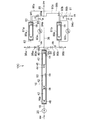
次に、本発明の第3実施形態を図4により説明する。本実施形態の逆浸透膜装置10Cは、図1又は図3に示す高圧容器16及びその内部構造と同一の構成を有し、複数の逆浸透膜エレメント42が直列に配置された高圧容器16を有する。高圧容器16の入口端に清澄海水導入路18が接続され、高圧容器16の出口開口16cに接続された濃縮海水流出路54は、分岐流出路80a及び80bに分岐し、分岐流出路80aは高圧容器81aの入口開口82に接続され、分岐流出路80bは高圧容器81bの入口開口に接続されている。高圧容器81a、81b及びその内部構造は、前記第1実施形態及び前記第2実施形態の高圧容器12a、12bの内部構造と同一である。
次に、本発明の第3実施形態を図4により説明する。本実施形態の逆浸透膜装置10Cは、図1又は図3に示す高圧容器16及びその内部構造と同一の構成を有し、複数の逆浸透膜エレメント42が直列に配置された高圧容器16を有する。高圧容器16の入口端に清澄海水導入路18が接続され、高圧容器16の出口開口16cに接続された濃縮海水流出路54は、分岐流出路80a及び80bに分岐し、分岐流出路80aは高圧容器81aの入口開口82に接続され、分岐流出路80bは高圧容器81bの入口開口に接続されている。高圧容器81a、81b及びその内部構造は、前記第1実施形態及び前記第2実施形態の高圧容器12a、12bの内部構造と同一である。
高圧容器81aには1個の逆浸透膜エレメント85aが内蔵され、高圧容器81bには、1個の逆浸透膜エレメント85bが内蔵されている。逆浸透膜エレメント85a及び85bで膜分離された透過水pwは、夫々透過水流出路86a及び86bから透過水集合路88に流出する。濃縮海水csは、出口開口84から濃縮海水流出路90a及び90bに流出し、濃縮海水集合路91に合流する。また、分岐流出路80aを流れる濃縮海水csと、濃縮海水流出路90aを流れる濃縮海水csとの差圧を検出する差圧計92aが設けられ、分岐流出路80bを流れる濃縮海水csと、濃縮海水流出路90bを流れる濃縮海水csとの差圧を検出する差圧計92bが設けられている。
さらに、濃縮海水流出路90a及び90bには、夫々洗浄液注入路94a及び94bが接続されている。分岐流出路80a及び80bには、夫々仕切弁98a及び98bが設けられ、かつ夫々洗浄液排出路96a及び96bが接続されている。また、濃縮海水流出路90a及び90bには、夫々仕切弁99a及び99bが設けられている。
かかる構成において、高圧容器16に内蔵された複数の逆浸透膜エレメント42で順々に濃縮された濃縮海水csは、高圧容器81a又は81bの一方又は両方に導入され、一方が保守点検を行うときは他方のみに濃縮海水csが導入される。
前述のように、最終段の逆浸透膜エレメント85a又は85bに導入される濃縮海水csには、CaやMgなどの高濃度の金属イオンが含まれている。これらの金属イオンが海水中に溶融しているCO2などと反応し、スケールを生成するため、逆浸透膜エレメント85a及び85bの逆浸透膜に堆積するスケールの堆積量が急激に増加する。
前述のように、最終段の逆浸透膜エレメント85a又は85bに導入される濃縮海水csには、CaやMgなどの高濃度の金属イオンが含まれている。これらの金属イオンが海水中に溶融しているCO2などと反応し、スケールを生成するため、逆浸透膜エレメント85a及び85bの逆浸透膜に堆積するスケールの堆積量が急激に増加する。
逆浸透膜装置10Cの運転中、差圧計66、92a又は92bの検出値が閾値を超えたら、閾値を超えた差圧計に対応した高圧容器への濃縮海水csの導入を停止し、洗浄工程を行う。この洗浄工程は前記第1実施形態と同様の方法を行う。例えば、差圧計92aの検出値が閾値を超えたとき、仕切弁98a、98b、99a及び99bを操作し、逆浸透膜エレメント85aへの清澄海水swの通水を停止し、洗浄工程に移行する。
洗浄工程では、まず、洗浄液注入路94aから洗浄液を注入し、逆浸透膜エレメント85aの表面に接するように洗浄液流を形成させた後、洗浄水排出路96aから洗浄液を排出する。高圧容器81bに内蔵された逆浸透膜エレメント85bを洗浄する場合も同様の操作をする。
洗浄工程では、まず、洗浄液注入路94aから洗浄液を注入し、逆浸透膜エレメント85aの表面に接するように洗浄液流を形成させた後、洗浄水排出路96aから洗浄液を排出する。高圧容器81bに内蔵された逆浸透膜エレメント85bを洗浄する場合も同様の操作をする。
本実施形態によれば、ファウリングが激しい最終段の逆浸透膜エレメント85a、85bを内蔵した高圧容器81a及び81bを濃縮海水流出路54に対して並列に配置し、一方の洗浄作業を行う時でも、他方の運転を継続できるので、逆浸透膜装置10Cの稼動率を高く維持でき、安定運転を可能にする。また、高圧容器16に内蔵された逆浸透膜エレメント42とは別に、洗浄頻度が頻繁な逆浸透膜エレメント85a又は85bのみを洗浄するので、洗浄薬剤投入の無駄を省き、低コスト化できる。
さらに、逆浸透膜エレメント85a又は85bのみを内蔵した高圧容器81a又は81bを開放すればよいので、洗浄作業の手間を省くことができると共に、洗浄に要する時間を短縮できる。
さらに、逆浸透膜エレメント85a又は85bのみを内蔵した高圧容器81a又は81bを開放すればよいので、洗浄作業の手間を省くことができると共に、洗浄に要する時間を短縮できる。
また、洗浄液の流れが逆浸透膜に作用することで、逆浸透膜に付着したファウリング物質を除去するようにしているので、酸やアルカリなどの強力な洗浄力を有する化学薬品の洗浄能力に頼る必要がなく、環境負荷の小さい洗浄が可能となる。
(実施形態4)
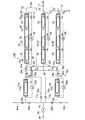
次に、本発明の第4実施形態を図5に基づいて説明する。本実施形態の逆浸透膜装置10Dにおいて、ポンプ20によって清澄海水導入路18から供給された清澄海水swは、導入分岐路18a及び18bを介して高圧容器12a又は12bに流入する。高圧容器12a又は12bには夫々1段目の逆浸透膜エレメント14a又は14bが内蔵されている。清澄海水swは高圧容器12a又は12bで膜分離され、透過水流出路34a又は34bに流出した透過水pwは、透過水集合路36から透過水集合路88に流出する。
次に、本発明の第4実施形態を図5に基づいて説明する。本実施形態の逆浸透膜装置10Dにおいて、ポンプ20によって清澄海水導入路18から供給された清澄海水swは、導入分岐路18a及び18bを介して高圧容器12a又は12bに流入する。高圧容器12a又は12bには夫々1段目の逆浸透膜エレメント14a又は14bが内蔵されている。清澄海水swは高圧容器12a又は12bで膜分離され、透過水流出路34a又は34bに流出した透過水pwは、透過水集合路36から透過水集合路88に流出する。
高圧容器12a又は12bから濃縮海水流出分岐路38a又は38bに流出した濃縮海水csは、濃縮海水集合路40に流出する。濃縮海水集合路40に対して、複数の高圧容器16が並列に配置され、高圧容器16には、2段目から最終段の前段までの複数の逆浸透膜エレメント42が直列に配置されている。濃縮海水流出路40に流出した濃縮海水csは、いずれかの高圧容器16に流入し膜分離される。高圧容器16から透過水流出路70に流出した透過水pwは、透過水集合路71を介して透過水集合路88に合流する。
いずれかの高圧容器16から濃縮海水流出路72に流出した濃縮海水csは、濃縮海水集合路73に合流する。濃縮海水集合路73に対して、高圧容器81a及び81bが並列に配置されている。高圧容器81a及び81bには、夫々最終段の逆浸透膜エレメント85a及び85bが内蔵されている。濃縮海水csは、濃縮海水集合路73から高圧容器81a又は81bに流入し膜分離される。高圧容器81a及び81bから透過水流出路86a又は86bに流出した透過水pwは、透過水集合路88に流出する。高圧容器81a及び81bから濃縮海水流出路90a又は90bに流出した濃縮海水csは、濃縮海水集合路91に合流し排出される。
高圧容器12a、12b、16及びその内部構造は、第1実施形態及び第2実施形態で用いられる高圧容器12a、12b、16及びその内部構造と同一である。また、高圧容器81a及び81b及びその内部構造は、前記第3実施形態で用いられる高圧容器81a及び81b及びその内部構造と同一である。
高圧容器12aには、導入分岐路18aを流れる清澄海水swの圧力と、濃縮海水流出路38aを流れる濃縮海水csの圧力との差圧を検出する差圧計56aが設けられ、高圧容器12bには、導入分岐路18bを流れる清澄海水swの圧力と、濃縮海水流出路38bを流れる濃縮海水csの圧力との差圧を検出する差圧計56bが設けられている。
また、複数の高圧容器16には夫々濃縮海水集合路40を流れる濃縮海水csの圧力と、濃縮海水排出路70を流れる濃縮海水csの圧力との差圧を検出する差圧計66が設けられている。
また、複数の高圧容器16には夫々濃縮海水集合路40を流れる濃縮海水csの圧力と、濃縮海水排出路70を流れる濃縮海水csの圧力との差圧を検出する差圧計66が設けられている。
さらに、高圧容器81aには、濃縮海水集合路73を流れる濃縮海水csの圧力と、濃縮海水流出路90aを流れる濃縮海水csの圧力との差を検出する差圧計92aが設けられ、高圧容器81bには、濃縮海水集合路73を流れる濃縮海水csの圧力と、濃縮海水流出路90bを流れる濃縮海水csの圧力との差を検出する差圧計92bが設けられている。
また、高圧容器12a及び12bから透過水pwが流出する透過水流出路34a及び34bに、夫々仕切弁74a及び74bが設けられている。そして、仕切弁58aの上流で導入分岐路18aから分岐し、仕切弁74aの上流で透過水流出路34aに接続するバイパス路76aが設けられている。また、仕切弁58bの上流で導入分岐路18bから分岐し、仕切弁74bの上流で透過水流出路34bに接続するバイパス路76bが設けられている。バイパス路76a及び76bには、夫々仕切弁77a及び77bが設けられ、透過水流出路34a及び34bには、洗浄工程時に、洗浄液として供給される清澄海水swを排出する清澄海水排出路78a及び78bが設けられている。
濃縮海水流出路90a及び90bには、夫々洗浄液注入路94a及び94bが接続されると共に、夫々仕切弁99a及び99bが設けられている。分岐流出路80a及び80bには、夫々洗浄液排出路96a及び96bが分岐されると共に、夫々仕切弁98a及び98bが設けられている。
前記いずれかの差圧計の検出値が閾値を超えると、閾値を超えた高圧容器への被処理水の導入を止め、洗浄作業が開始される。高圧容器12a又は12bの洗浄作業は、例えば、高圧容器12aの場合、第2実施形態で説明したように、仕切弁58a、74a及び60aを閉とし、仕切弁77aを開とする。その後、ポンプ20で逆浸透膜エレメント14aの逆浸透膜で発生する浸透圧より低い圧力で、清澄海水swをバイパス路76aから透過水流出路34aに供給する。
これによって、透過水pwと清澄海水swとが混じった混合流が逆浸透膜エレメント14aの逆浸透膜に到達し、この混合流のうち透過水pwのみが逆浸透膜を通過する。このとき発生する清澄海水swの浸透圧と浸透圧をもたない透過水pwとの間の圧力差によって、透過水pwを透過水流出路34aから逆浸透膜を透過させる。透過水pwの透過によって逆浸透膜に堆積しているファウリング物質を剥離除去する。
逆浸透膜を正浸透現象により通過した透過水pwは、洗浄液排出路64aから排出され、逆浸透膜エレメント14aに供給にした清澄海水swは、清澄海水排出路78aから排出される。高圧容器12bに内蔵された逆浸透膜エレメント14bを洗浄する場合も同様の操作を行う。
逆浸透膜を正浸透現象により通過した透過水pwは、洗浄液排出路64aから排出され、逆浸透膜エレメント14aに供給にした清澄海水swは、清澄海水排出路78aから排出される。高圧容器12bに内蔵された逆浸透膜エレメント14bを洗浄する場合も同様の操作を行う。
高圧容器81a又は81bの洗浄作業は、例えば、高圧容器81aの場合、第3実施形態で説明したように、仕切弁98a、98b、99a及び99bを操作し、逆浸透膜エレメント81aへの清澄海水swの通水を停止し、洗浄工程に移行する。
洗浄工程では、まず、洗浄液注入路94aから洗浄液aを注入し、逆浸透膜エレメント85aの表面に接するように洗浄液流を形成させた後、洗浄水排出路96aから洗浄液を排出する。高圧容器81bに内蔵された逆浸透膜エレメント85bを洗浄する場合も同様の操作をする。洗浄の頻度が少なくて済む高圧容器16の場合も、高圧容器12a、12b又は高圧容器81a、81bに準じて洗浄作業を行う。
洗浄工程では、まず、洗浄液注入路94aから洗浄液aを注入し、逆浸透膜エレメント85aの表面に接するように洗浄液流を形成させた後、洗浄水排出路96aから洗浄液を排出する。高圧容器81bに内蔵された逆浸透膜エレメント85bを洗浄する場合も同様の操作をする。洗浄の頻度が少なくて済む高圧容器16の場合も、高圧容器12a、12b又は高圧容器81a、81bに準じて洗浄作業を行う。
本実施形態によれば、ファウリングが激しい1段目の逆浸透膜エレメント14a、14bを内蔵した高圧容器12a、12bを清澄海水導入路18に対して並列に配置すると共に、最終段の逆浸透膜エレメント85a、85bを内蔵した高圧容器81a、81bを濃縮海水集合路73に対して並列に配置したので、一方の洗浄作業を行う時でも、他方の運転を継続できる。そのため、逆浸透膜装置10Dの稼動率を高く維持でき、安定運転を可能にする。また、高圧容器16に内蔵された逆浸透膜エレメント42とは別に、洗浄頻度が頻繁な逆浸透膜エレメント14a、14b又は逆浸透膜エレメント85a、85bのみを洗浄するので、洗浄薬剤投入の無駄を省き、低コスト化できる。
さらに、高圧容器12a、12b及び81a、81bの洗浄作業時、逆浸透膜エレメント14a又は14bのみを内蔵した高圧容器12a又は12b、あるいは逆浸透膜エレメント85a又は85bのみを内蔵した高圧容器81a又は81bを開放すればよいので、洗浄作業の手間を省くことができると共に、洗浄に要する時間を短縮できる。
また、高圧容器12a又は12bでは、清澄海水swの浸透圧を利用して逆浸透膜エレメントの洗浄を行っているので、ポンプ20を低動力で作動できる。また、洗浄液として強力な洗浄効果を有する化学薬品を使用することなく洗浄が可能になり、省エネで環境負荷が小さい洗浄を実現できる。
また、高圧容器81a又は81bでは、洗浄液の流れが逆浸透膜に作用することで、逆浸透膜に付着したファウリング物質を除去するようにしているので、酸やアルカリなどの強力な洗浄力を有する化学薬品の洗浄能力に頼る必要がなく、環境負荷の小さい洗浄が可能となる。
また、高圧容器81a又は81bでは、洗浄液の流れが逆浸透膜に作用することで、逆浸透膜に付着したファウリング物質を除去するようにしているので、酸やアルカリなどの強力な洗浄力を有する化学薬品の洗浄能力に頼る必要がなく、環境負荷の小さい洗浄が可能となる。
なお、前記実施形態はいずれもスパイラル型逆浸透膜エレメントを用いているが、本発明では、代わりに、平膜型逆浸透膜エレメントを用いてもよい。
本発明によれば、海水淡水化プラントなどに適応される逆浸透膜装置の洗浄に要する手間と時間を短縮し、逆浸透膜装置の稼動率を高め、安定運転を可能にする。
10A、10B,10C,10D,100 逆浸透膜装置
12a、12b、81a、81b 高圧容器(第1の高圧容器)
22、82 入口開口
24、26,83,84 出口開口
14a、14b、85a、85b 逆浸透膜エレメント(第1の逆浸透膜エレメント)
42 逆浸透膜エレメント(第2の逆浸透膜エレメント)
16 高圧容器(第2の高圧容器)
16a 入口開口
16b、16c 出口開口
18 清澄海水導入路
18a、18b 導入分岐路
20 ポンプ
28、44 センターパイプ
30、48 エンドキャップ
31、50 ブラインシール
32、46 コネクタ
34a、34b、52、70、86a、86b 透過水流出路
36、71、88 透過水集合路
38a、38b、54、72,90a、90b 濃縮海水流出路
40、73、91 濃縮海水集合路
56a、56b、66、92a、92b 差圧計
58a、58b、60a、60b、74a、74b、77a、77b、98a、98b、99a、99b 仕切弁
62a、62b、94a、94b 洗浄液注入路
64a、64b、96a、96b 洗浄液排出路
67 演算器
68 アラーム発信機
76a、76b バイパス路
78a、78b 清澄海水排出路
80a、80b 分岐流出路
a 洗浄液
cs 濃縮海水
cw 濃縮水
pw 透過水
sw 清澄海水
tw 被処理水
Claims (7)
- 複数の逆浸透膜エレメントが直列又は並列に配置され、原水を前処理して生成した被処理水を1段目の逆浸透膜エレメントから順々に濃縮水と透過水へ膜分離し、前記透過水を得るようにした逆浸透膜装置において、
前記被処理水の導入路に対して並列に配置され、前記複数の逆浸透膜エレメントのうち、前記被処理水の上流側である前段又は前記被処理水の下流側である後段にある第1の逆浸透膜エレメントを夫々内蔵した複数の第1の高圧容器群と、
前記複数の逆浸透膜エレメントのうち、前記第1の高圧容器群に対して直列に配置され、前記第1の逆浸透膜エレメント以外の第2の逆浸透膜エレメントが直列配置で内蔵された第2の高圧容器と、
前記第1の逆浸透膜エレメントの逆浸透膜に堆積したファウリング物質の堆積量を検出する堆積量検出手段と、
前記第1の逆浸透膜エレメントに堆積したファウリング物質が閾値を超えたとき、前記第1の逆浸透膜エレメントを内蔵した前記第1の高圧容器への被処理水の導入を停止し、被処理水を前記第1の逆浸透膜エレメントと並列に配置された他の第1の逆浸透膜エレメントに流入させる流路切換手段とを備えていることを特徴とする逆浸透膜装置。 - 前記第1の逆浸透膜エレメントの逆浸透膜に洗浄液を供給する洗浄液供給部と、
前記第1の逆浸透膜エレメントの逆浸透膜を洗浄した後の洗浄液を排出する洗浄液排出路とをさらに備え、
前記洗浄液が前記逆浸透膜に作用する剥離力によって、前記逆浸透膜に付着したファウリング物質を剥離するようにしたことを特徴とする請求項1に記載の逆浸透膜装置。 - 前記堆積量検出手段が、
前記第1の逆浸透膜エレメント入口側の被処理水導入路を流れる被処理水の圧力と、前記第1の逆浸透膜エレメントの濃縮水流出路を流れる濃縮水の圧力との差圧を検出する差圧検出手段と、
前記差圧検出手段の検出値からファウリング物質の堆積量を算出する堆積量算出手段とを備えていることを特徴とする請求項1に記載の逆浸透膜装置。 - 前記堆積量検出手段で検出されたファウリング物質の堆積量が閾値を超えた時、アラームを発信するアラーム発信機をさらに備えていることを特徴とする請求項1~3のいずれかの項に記載の逆浸透膜装置。
- 前記第2の高圧容器が、前記第1の高圧容器に設けられた濃縮水流出路に対して複数個並列に配置されていることを特徴とする請求項1に記載の逆浸透膜装置。
- 請求項4に記載された逆浸透膜装置の運転方法において、
前記アラーム発信機がアラームを発信したとき、ファウリング物質が閾値を超えた前記第1の逆浸透膜エレメントに対して被処理水の導入を停止させ、前記流路切換手段により、被処理水(sw)を他の第1の逆浸透膜エレメントに導入する流路切換工程と、
前記洗浄水供給部から洗浄液を供給し、該洗浄液の流れによって、前記第1の逆浸透膜エレメントの逆浸透膜に付着したファウリング物質を剥離させた後、該洗浄液を前記洗浄水排出路から排出する洗浄工程とからなることを特徴とする逆浸透膜装置の運転方法。 - 前記洗浄工程において、
前記洗浄液として被処理水を、透過水路を介し前記第1の逆浸透膜エレメントの逆浸透膜に発生する浸透圧より低圧で前記第1の逆浸透膜エレメントに供給し、
前記被処理水の浸透圧と浸透圧をもたない透過水との間の圧力差によって、前記透過水を前記透過水路側から前記逆浸透膜を透過させることを特徴とする請求項6に記載の逆浸透膜装置の運転方法。
Priority Applications (3)
| Application Number | Priority Date | Filing Date | Title |
|---|---|---|---|
| US14/769,721 US10202291B2 (en) | 2013-02-25 | 2014-02-10 | Reverse osmosis membrane apparatus and method of operating same |
| EP14754840.8A EP2959963A4 (en) | 2013-02-25 | 2014-02-10 | REVERSE OSMOSIS MEMBRANE DEVICE AND METHOD FOR OPERATING THEREOF |
| SA515360936A SA515360936B1 (ar) | 2013-02-25 | 2015-08-23 | جهاز غشاء تناضح عكسي وطريقة لتشغيله |
Applications Claiming Priority (2)
| Application Number | Priority Date | Filing Date | Title |
|---|---|---|---|
| JP2013-035023 | 2013-02-25 | ||
| JP2013035023A JP6049498B2 (ja) | 2013-02-25 | 2013-02-25 | 逆浸透膜装置及びその運転方法 |
Publications (1)
| Publication Number | Publication Date |
|---|---|
| WO2014129340A1 true WO2014129340A1 (ja) | 2014-08-28 |
Family
ID=51391135
Family Applications (1)
| Application Number | Title | Priority Date | Filing Date |
|---|---|---|---|
| PCT/JP2014/053008 Ceased WO2014129340A1 (ja) | 2013-02-25 | 2014-02-10 | 逆浸透膜装置及びその運転方法 |
Country Status (5)
| Country | Link |
|---|---|
| US (1) | US10202291B2 (ja) |
| EP (1) | EP2959963A4 (ja) |
| JP (1) | JP6049498B2 (ja) |
| SA (1) | SA515360936B1 (ja) |
| WO (1) | WO2014129340A1 (ja) |
Cited By (1)
| Publication number | Priority date | Publication date | Assignee | Title |
|---|---|---|---|---|
| WO2015188776A1 (zh) * | 2014-06-06 | 2015-12-17 | 王桂林 | 一种应用于海水淡化的多级反渗透膜装置 |
Families Citing this family (21)
| Publication number | Priority date | Publication date | Assignee | Title |
|---|---|---|---|---|
| JP5974386B2 (ja) * | 2013-02-28 | 2016-08-23 | 株式会社日立製作所 | 海水淡水化システム |
| JP6041798B2 (ja) | 2013-12-20 | 2016-12-14 | 三菱重工業株式会社 | 逆浸透膜濾過装置 |
| JP6399895B2 (ja) * | 2014-10-30 | 2018-10-03 | 株式会社日立製作所 | 逆浸透処理システムおよび逆浸透処理方法 |
| CN105093082A (zh) * | 2015-08-31 | 2015-11-25 | 上海正泰电源系统有限公司 | 一种直流故障电弧检测方法 |
| CN105800815B (zh) * | 2016-05-25 | 2019-05-24 | 广州达意隆包装机械股份有限公司 | 一种船舰用海水淡化装置 |
| KR102004160B1 (ko) | 2016-12-22 | 2019-07-26 | 경희대학교 산학협력단 | 사물인터넷 환경에서 클라이언트 식별자를 이용하여 클라이언트 노드들을 논리적으로 그룹화하는 장치 및 방법 |
| JP2018140376A (ja) * | 2017-02-28 | 2018-09-13 | 株式会社日立製作所 | 逆浸透処理装置及び逆浸透処理方法 |
| CN106927542A (zh) * | 2017-05-17 | 2017-07-07 | 中创意德(北京)科技发展有限公司 | 一种紧凑型家用净水机和智能家用净水机 |
| WO2019051588A1 (en) * | 2017-09-12 | 2019-03-21 | Pani Energy Inc. | ADAPTIVE MEMBRANE SYSTEMS |
| ES2708126B2 (es) * | 2017-10-06 | 2019-09-18 | Moro Maria Teresa Bergaz | Metodo para el tratamiento de agua salobre o de mar mediante osmosis inversa |
| JP6967492B2 (ja) * | 2018-07-30 | 2021-11-17 | 株式会社神戸製鋼所 | 流体処理システム |
| US10947143B2 (en) | 2019-04-01 | 2021-03-16 | Saline Water Conversion Corporation | Desalination brine concentration system and method |
| US20210053848A1 (en) | 2019-08-22 | 2021-02-25 | Saline Water Conversion Corporation | Multi-Valent Ion Concentration Using Multi-Stage Nanofiltration |
| JP7239428B2 (ja) | 2019-09-04 | 2023-03-14 | オルガノ株式会社 | 水処理システム及び水処理方法 |
| JP7427890B2 (ja) * | 2019-09-12 | 2024-02-06 | 東洋紡エムシー株式会社 | 濃縮システム |
| JP7103513B2 (ja) * | 2020-02-14 | 2022-07-20 | 東レ株式会社 | ろ過特性予測による造水装置の制御方法、造水装置のトラブル判定方法、造水装置、造水装置の運転プログラム、造水装置のトラブル判定プログラム、および記録媒体 |
| JP7294185B2 (ja) | 2020-02-28 | 2023-06-20 | いすゞ自動車株式会社 | 運転支援方法及び運転支援装置 |
| JP7021285B2 (ja) * | 2020-04-28 | 2022-02-16 | ダイセン・メンブレン・システムズ株式会社 | 廃水処理システムとその運転方法 |
| JP6995923B2 (ja) * | 2020-04-28 | 2022-01-17 | ダイセン・メンブレン・システムズ株式会社 | 廃水処理システムとその運転方法 |
| EP4422783A4 (en) * | 2021-10-29 | 2025-10-29 | H2O Innovation Inc | PERMEATE DUCT SEGMENT FOR REVERSE OSMOSIS PROCESS AND FLEXIBLE DUCT SEGMENT FOR WATER TREATMENT PLANT |
| US11806668B2 (en) | 2021-12-14 | 2023-11-07 | Saline Water Conversion Corporation | Method and system for extraction of minerals based on divalent cations from brine |
Citations (11)
| Publication number | Priority date | Publication date | Assignee | Title |
|---|---|---|---|---|
| JPS6287605U (ja) * | 1985-11-22 | 1987-06-04 | ||
| JPS6359312A (ja) * | 1986-08-29 | 1988-03-15 | Kyocera Corp | 逆浸透淡水化装置の逆浸透膜モジユ−ル洗浄方法 |
| JPH07144120A (ja) * | 1993-11-26 | 1995-06-06 | Shinko Pantec Co Ltd | 逆浸透膜装置及び逆浸透膜装置の洗浄方法、ならびに逆浸透膜装置の洗浄運転方法 |
| JP2001029756A (ja) * | 1999-07-16 | 2001-02-06 | Nitto Denko Corp | スパイラル型膜モジュールを用いた処理システムおよびその運転方法 |
| JP2001170458A (ja) * | 1999-12-15 | 2001-06-26 | Meidensha Corp | 膜浄水処理における膜破断とファウリングの検出方法 |
| JP2001191071A (ja) | 2000-01-11 | 2001-07-17 | Kurita Water Ind Ltd | 膜分離装置の運転方法 |
| JP2001300264A (ja) | 2000-04-28 | 2001-10-30 | Toray Ind Inc | 逆浸透膜造水装置 |
| JP2005238135A (ja) * | 2004-02-27 | 2005-09-08 | Nitto Denko Corp | 膜分離装置の洗浄方法 |
| JP2008207158A (ja) * | 2007-02-28 | 2008-09-11 | Mrc Home Products Kk | 浄水装置 |
| JP2011120996A (ja) * | 2009-12-10 | 2011-06-23 | Panasonic Corp | 脱塩方法と装置 |
| JP2012130840A (ja) * | 2010-12-20 | 2012-07-12 | Hitachi Plant Technologies Ltd | 逆浸透処理装置 |
Family Cites Families (12)
| Publication number | Priority date | Publication date | Assignee | Title |
|---|---|---|---|---|
| JPH067787Y2 (ja) * | 1987-06-08 | 1994-03-02 | オルガノ株式会社 | 逆浸透膜装置 |
| JP3944973B2 (ja) | 1997-10-28 | 2007-07-18 | 栗田工業株式会社 | 逆浸透膜処理方法 |
| US6402954B1 (en) * | 1997-12-01 | 2002-06-11 | O'keefe, Jr. Patrick J. | Method and apparatus for monitoring and cleaning a fluid filter system |
| JP3900455B2 (ja) | 1999-11-05 | 2007-04-04 | 東レ株式会社 | 逆浸透膜装置とその運転方法、造水方法および制御装置 |
| JP2002361054A (ja) | 2001-06-12 | 2002-12-17 | Nkk Corp | 膜ろ過装置の洗浄方法 |
| US20050067341A1 (en) * | 2003-09-25 | 2005-03-31 | Green Dennis H. | Continuous production membrane water treatment plant and method for operating same |
| AU2005254337B2 (en) * | 2004-06-21 | 2010-04-15 | Membrane Recovery Ltd | Ro membrane cleaning method |
| JP2006122787A (ja) | 2004-10-27 | 2006-05-18 | Kobelco Eco-Solutions Co Ltd | 海水淡水化方法 |
| GB0702214D0 (en) * | 2007-02-06 | 2007-03-14 | H2Oil & Gas Ltd | Filtration system |
| WO2009156547A1 (es) | 2008-06-26 | 2009-12-30 | Acciona Agua, S.A.U. | Procedimiento de desalinización y eliminación de boro del agua y equipo para llevar a cabo dicho procedimiento |
| JP5573324B2 (ja) | 2010-04-20 | 2014-08-20 | 三浦工業株式会社 | 純水製造システム |
| US20120145634A1 (en) | 2010-12-10 | 2012-06-14 | Water Intellectual Properties, Inc. | High Efficiency Water Purification System |
-
2013
- 2013-02-25 JP JP2013035023A patent/JP6049498B2/ja not_active Expired - Fee Related
-
2014
- 2014-02-10 EP EP14754840.8A patent/EP2959963A4/en not_active Withdrawn
- 2014-02-10 US US14/769,721 patent/US10202291B2/en not_active Expired - Fee Related
- 2014-02-10 WO PCT/JP2014/053008 patent/WO2014129340A1/ja not_active Ceased
-
2015
- 2015-08-23 SA SA515360936A patent/SA515360936B1/ar unknown
Patent Citations (11)
| Publication number | Priority date | Publication date | Assignee | Title |
|---|---|---|---|---|
| JPS6287605U (ja) * | 1985-11-22 | 1987-06-04 | ||
| JPS6359312A (ja) * | 1986-08-29 | 1988-03-15 | Kyocera Corp | 逆浸透淡水化装置の逆浸透膜モジユ−ル洗浄方法 |
| JPH07144120A (ja) * | 1993-11-26 | 1995-06-06 | Shinko Pantec Co Ltd | 逆浸透膜装置及び逆浸透膜装置の洗浄方法、ならびに逆浸透膜装置の洗浄運転方法 |
| JP2001029756A (ja) * | 1999-07-16 | 2001-02-06 | Nitto Denko Corp | スパイラル型膜モジュールを用いた処理システムおよびその運転方法 |
| JP2001170458A (ja) * | 1999-12-15 | 2001-06-26 | Meidensha Corp | 膜浄水処理における膜破断とファウリングの検出方法 |
| JP2001191071A (ja) | 2000-01-11 | 2001-07-17 | Kurita Water Ind Ltd | 膜分離装置の運転方法 |
| JP2001300264A (ja) | 2000-04-28 | 2001-10-30 | Toray Ind Inc | 逆浸透膜造水装置 |
| JP2005238135A (ja) * | 2004-02-27 | 2005-09-08 | Nitto Denko Corp | 膜分離装置の洗浄方法 |
| JP2008207158A (ja) * | 2007-02-28 | 2008-09-11 | Mrc Home Products Kk | 浄水装置 |
| JP2011120996A (ja) * | 2009-12-10 | 2011-06-23 | Panasonic Corp | 脱塩方法と装置 |
| JP2012130840A (ja) * | 2010-12-20 | 2012-07-12 | Hitachi Plant Technologies Ltd | 逆浸透処理装置 |
Non-Patent Citations (1)
| Title |
|---|
| See also references of EP2959963A4 * |
Cited By (1)
| Publication number | Priority date | Publication date | Assignee | Title |
|---|---|---|---|---|
| WO2015188776A1 (zh) * | 2014-06-06 | 2015-12-17 | 王桂林 | 一种应用于海水淡化的多级反渗透膜装置 |
Also Published As
| Publication number | Publication date |
|---|---|
| EP2959963A1 (en) | 2015-12-30 |
| JP6049498B2 (ja) | 2016-12-21 |
| JP2014161797A (ja) | 2014-09-08 |
| SA515360936B1 (ar) | 2019-02-04 |
| US10202291B2 (en) | 2019-02-12 |
| EP2959963A4 (en) | 2016-10-19 |
| US20160002072A1 (en) | 2016-01-07 |
Similar Documents
| Publication | Publication Date | Title |
|---|---|---|
| JP6049498B2 (ja) | 逆浸透膜装置及びその運転方法 | |
| AU2022200930B2 (en) | Water purification systems and methods having pressurized draw stream | |
| AU2005254337B2 (en) | Ro membrane cleaning method | |
| EP2633898A1 (en) | Hollow fiber membrane filtration device and method for washing hollow fiber membrane module | |
| US9833743B2 (en) | Reverse osmosis treatment device and method for cleaning reverse osmosis treatment device | |
| WO2010122336A3 (en) | Water treatment | |
| JP6399896B2 (ja) | 逆浸透処理装置 | |
| JP6344114B2 (ja) | 水処理装置及び水処理設備の洗浄方法 | |
| CN102688694B (zh) | 一种多孔陶瓷膜在线反冲洗装置 | |
| KR20150080515A (ko) | 제탁막 모듈의 운전 방법 | |
| TW200404601A (en) | Operating method of separation membrane module and separation membrane apparatus | |
| CN206705745U (zh) | 原水反渗透净化系统 | |
| AU2024339086B2 (en) | Membrane based in-line fouling monitor for performance tracking in reverse osmosis and nano-filtration systems | |
| WO2018159561A1 (ja) | 逆浸透処理装置及び逆浸透処理方法 | |
| JP2013212497A (ja) | 水処理方法 | |
| KR101642393B1 (ko) | 역삼투 멤브레인 트레인별 삼투압 역세척 시스템 및 방법 | |
| JP6398131B2 (ja) | 水処理装置、及びその運転方法 | |
| JP6428017B2 (ja) | 水処理装置及び水処理設備の洗浄方法 | |
| CN109331664B (zh) | 一种超滤膜冲洗装置及方法 | |
| CN110960986A (zh) | 一种环境友好的反渗透清洗装置及方法 | |
| CN210874865U (zh) | 一种膜设备清洗系统 | |
| CN116059833B (zh) | 煤化工循环水污堵状态人工智能判断系统 | |
| CN220766622U (zh) | 一种反渗透膜污水处理装置 | |
| JP2014221459A (ja) | 海水淡水化システム | |
| JP5802580B2 (ja) | 膜ろ過装置 |
Legal Events
| Date | Code | Title | Description |
|---|---|---|---|
| 121 | Ep: the epo has been informed by wipo that ep was designated in this application |
Ref document number: 14754840 Country of ref document: EP Kind code of ref document: A1 |
|
| WWE | Wipo information: entry into national phase |
Ref document number: 14769721 Country of ref document: US Ref document number: 2014754840 Country of ref document: EP |
|
| NENP | Non-entry into the national phase |
Ref country code: DE |