WO2014129577A1 - 表示装置 - Google Patents
表示装置 Download PDFInfo
- Publication number
- WO2014129577A1 WO2014129577A1 PCT/JP2014/054131 JP2014054131W WO2014129577A1 WO 2014129577 A1 WO2014129577 A1 WO 2014129577A1 JP 2014054131 W JP2014054131 W JP 2014054131W WO 2014129577 A1 WO2014129577 A1 WO 2014129577A1
- Authority
- WO
- WIPO (PCT)
- Prior art keywords
- light
- illumination
- layer
- color
- illuminated
- Prior art date
- Legal status (The legal status is an assumption and is not a legal conclusion. Google has not performed a legal analysis and makes no representation as to the accuracy of the status listed.)
- Ceased
Links
Images


Classifications
-
- G—PHYSICS
- G02—OPTICS
- G02B—OPTICAL ELEMENTS, SYSTEMS OR APPARATUS
- G02B5/00—Optical elements other than lenses
- G02B5/20—Filters
- G02B5/201—Filters in the form of arrays
-
- G—PHYSICS
- G09—EDUCATION; CRYPTOGRAPHY; DISPLAY; ADVERTISING; SEALS
- G09F—DISPLAYING; ADVERTISING; SIGNS; LABELS OR NAME-PLATES; SEALS
- G09F13/00—Illuminated signs; Luminous advertising
- G09F13/04—Signs, boards or panels, illuminated from behind the insignia
- G09F13/12—Signs, boards or panels, illuminated from behind the insignia using a transparent mirror or other light reflecting surface transparent to transmitted light whereby a sign, symbol, picture or other is visible only when illuminated
-
- G—PHYSICS
- G02—OPTICS
- G02B—OPTICAL ELEMENTS, SYSTEMS OR APPARATUS
- G02B6/00—Light guides; Structural details of arrangements comprising light guides and other optical elements, e.g. couplings
- G02B6/0001—Light guides; Structural details of arrangements comprising light guides and other optical elements, e.g. couplings specially adapted for lighting devices or systems
- G02B6/0011—Light guides; Structural details of arrangements comprising light guides and other optical elements, e.g. couplings specially adapted for lighting devices or systems the light guides being planar or of plate-like form
- G02B6/0033—Means for improving the coupling-out of light from the light guide
- G02B6/0035—Means for improving the coupling-out of light from the light guide provided on the surface of the light guide or in the bulk of it
- G02B6/004—Scattering dots or dot-like elements, e.g. microbeads, scattering particles, nanoparticles
- G02B6/0043—Scattering dots or dot-like elements, e.g. microbeads, scattering particles, nanoparticles provided on the surface of the light guide
-
- G—PHYSICS
- G09—EDUCATION; CRYPTOGRAPHY; DISPLAY; ADVERTISING; SEALS
- G09F—DISPLAYING; ADVERTISING; SIGNS; LABELS OR NAME-PLATES; SEALS
- G09F13/00—Illuminated signs; Luminous advertising
- G09F13/04—Signs, boards or panels, illuminated from behind the insignia
- G09F13/0418—Constructional details
- G09F13/044—Signs, boards or panels mounted on vehicles
-
- G—PHYSICS
- G09—EDUCATION; CRYPTOGRAPHY; DISPLAY; ADVERTISING; SEALS
- G09F—DISPLAYING; ADVERTISING; SIGNS; LABELS OR NAME-PLATES; SEALS
- G09F13/00—Illuminated signs; Luminous advertising
- G09F13/04—Signs, boards or panels, illuminated from behind the insignia
- G09F13/08—Signs, boards or panels, illuminated from behind the insignia using both translucent and non-translucent layers
Definitions
- the present invention relates to a display device used for an operation panel of various electronic devices, and more particularly to a display device in which an illuminated display pattern is not visually recognized when not illuminated.
- Patent Document 1 discloses an operation panel device 801 as shown in FIG. 11A and 11B are diagrams illustrating the operation panel device 801.
- FIG. 11A is a front view of the operation panel device 801 in the air conditioner operation mode
- FIG. 11B is an audio diagram of the operation panel device 801.
- FIG. 11C is a front view in the operation mode
- FIG. 11C is a main part sectional view schematically showing the structure of the front plate 804 that is blacked out of the operation panel device 801.
- the air conditioner display unit 804a When the operation panel device 801 is in the air conditioner operation mode, as shown in FIG. 11A, the air conditioner display unit 804a is illuminated from behind the front plate 804, and the display pattern is visually recognized. As shown in (b), the audio display unit 804b is illuminated from behind the front plate 804 so that the display pattern is visible. On the other hand, in the air conditioner operation mode, the audio display unit 804b is not visually recognized, and in the audio operation mode, the air conditioner display unit 804a is not visually recognized, which is a so-called blackout state. In order to create this blackout state, the front plate 804 of the operation panel device 801 is subjected to blackout processing.
- the front plate 804 is formed with a light-transmitting black coating 842 (black layer) on the entire back surface of the transparent panel 841, and then illuminated region 804c (shown in FIG. 11A). Except for the air conditioner display portion 804a and the portion corresponding to the audio display portion 804b shown in FIG. 11B, a light-shielding black coating 843 is formed. Further, a translucent white coating film 844 (smoke layer) is formed so as to cover the illumination region 804c. With this configuration, the illumination area 804c is illuminated with the same color as the emission color when illuminated from the rear, and is visually recognized by the user, but the black coating 842 is more visible than the illumination area 804c when not illuminated. Since it is on the front side, it exhibits the same black color (dark color) as the black coating film 842. Therefore, the illumination region 804c is prevented from being visually recognized when not illuminated.
- Patent Document 2 discloses a display device 901 as shown in FIG. 12A and 12B are diagrams illustrating the display device 901.
- FIG. 12A is a front view showing a design surface of the display panel 907 of the display device 901, and FIG. It is sectional drawing in the BB line shown to a).
- the display device 901 includes a display panel 907 and a light source 908 arranged on the back surface of the display panel 907.
- the display panel 907 includes a diffusion sheet 909 that is disposed to face the light source 908 and diffuses light, a transparent smoke-colored resin layer 910 that is disposed in front of the diffusion sheet 909, a resin layer 910, and an adhesive layer 911.
- a display illumination color layer 912 that is interposed therebetween. Furthermore, it has a smoked smoke layer 913 disposed on the front surface of the display illumination color layer 912, and a black layer 914 (black layer) disposed on the front surface of the smoke layer 913.
- the black layer 914 includes a non-illumination area 917 where light from the light source 908 is blocked and an illumination area 918 through which the light is transmitted.
- the illumination area 918 includes characters and figures shown in FIG. A display pattern PP such as a picture is formed. With this configuration, the display pattern PP of the illumination area 918 is illuminated with the same color as the light emission color when the light source 908 is turned on and visually recognized by the user, but when the light source 908 is not turned on, the smoke layer 913 is smoked. The color is visually recognized and exhibits a color (dark color) similar to the dark color of the non-illuminated region 917. Therefore, it is possible to reduce the visibility of the display pattern PP when it is not lit.
- the black coating 842 or the smoke layer 913 is formed so that the display portion (the illumination region 804c or the illumination region 918) and other portions are visually recognized as dark colors.
- the display portion the illumination region 804c or the illumination region 9148
- other portions are visually recognized as dark colors.
- This invention solves the subject mentioned above, and it aims at providing the display apparatus with which a display pattern of an illumination part is not visually recognized by a simple structure at the time of non-lighting.
- a display device includes a display panel having an illuminating unit and a non-illuminating unit, and an illuminating member that is disposed on the back side of the display panel and illuminates the illuminating unit.
- the display panel includes: a light-transmitting base material; and a light-transmitting smoke layer formed on a back surface of the base material on the illumination member side, the smoke layer A light-shielding color layer is formed on the main surface of the light-emitting member, and the color layer has an opening for forming the light-emitting portion.
- the display device of the present invention can form a smoke layer on the back surface of the base material of the display panel, thereby making the background colors of the illuminated part and the non-illuminated part more uniform, Light incident on the smoke layer can be diffused. For this reason, it is possible to make the boundary between the illumination part and the non-illumination part less visible to the user. Furthermore, by forming a non-black color layer on the main surface of the smoke layer on the side of the illuminating member, the user can visually recognize the reflected light at the interface between the smoke layer and the color layer of the non-illuminated part when not illuminated. become.
- the reflected light at this interface can be adjusted to bring the color tone of the non-illuminated part visually recognized by the user closer to the color tone of the illuminated part.
- the transmitted light transmitted through the smoke layer can be adjusted, so that the color tone of the non-illuminated portion visually recognized by the user can be made closer to the color tone of the illuminated portion.
- the display device of the present invention is characterized in that a light-shielding black layer is formed on the main surface of the color layer on the side of the illumination member.
- the light from the illumination member can be shielded by the black layer. For this reason, at the time of illumination, transmission of light to the non-illuminated part side can be surely prevented. Further, even when the color layer has a defect such as a pinhole, it is possible to prevent light from being transmitted to the non-illuminated portion side. Thereby, at the time of illumination, the difference between the illuminated part and the non-illuminated part can be clarified, and the designability of the applied product can be enhanced.
- the display device of the present invention is characterized in that the smoke layer has a light transmittance of 1% or more.
- the illumination unit more light can be transmitted through the illumination unit.
- the user can visually recognize the display pattern of the illumination unit more brightly.
- the luminance of the illuminating member to be selected can be kept low, and the power consumption of the display device can be reduced.
- the display device of the present invention is characterized in that the illumination member has a light emission source that directly illuminates the illumination unit.
- the illumination part can be directly illuminated, and the display pattern can be displayed more brightly.
- the display device of the present invention is characterized in that the illumination member includes a light emitting light source and a light guide having a light incident portion for receiving light from the light emitting light source.
- the light from the light emitting light source can be efficiently guided to the illumination unit.
- the illumination part can be illuminated uniformly, and the quality of the applied product can be enhanced.
- the display device of the present invention by forming the smoke layer on the back surface of the base material of the display panel, the background colors of the illuminated part and the non-illuminated part can be made more uniform, and the incident light is incident on the smoke layer. Light can be diffused. For this reason, it is possible to make the boundary between the illumination part and the non-illumination part less visible to the user. Furthermore, by forming a non-black color layer on the main surface of the smoke layer on the side of the illuminating member, the user can visually recognize the reflected light at the interface between the smoke layer and the color layer of the non-illuminated part when not illuminated. become.
- the reflected light at this interface can be adjusted to bring the color tone of the non-illuminated part visually recognized by the user closer to the color tone of the illuminated part.
- the transmitted light transmitted through the smoke layer can be adjusted, so that the color tone of the non-illuminated portion visually recognized by the user can be made closer to the color tone of the illuminated portion.
- FIG. 2A is a front view of the display device in an “audio operation mode”
- FIG. 2A is a front view of the display apparatus in a mode.
- FIG. 2B is a section lineblock diagram explaining the display of a 1st embodiment of the present invention.
- FIG. 1st Embodiment of this invention Comprising: It is the cross-sectional block diagram which showed an example of the optical path in a display apparatus.
- FIG.11 (a) is a front view in the air-conditioner operation mode of an operation panel apparatus
- FIG.11 (b) is in the audio operation mode of an operation panel apparatus
- 11 is a front view
- FIG. 11C is a cross-sectional view of an essential part schematically showing the structure of the front plate that is blacked out of the operation panel device.
- FIG.12 (a) is the front view which showed the design surface of the display panel of a display apparatus
- FIG.12 (b) is FIG.12 (a). It is sectional drawing in the BB line shown.
- FIG. 1 is a diagram for explaining the display device 101 according to the first embodiment of the present invention, and is a perspective view showing an appearance of a vehicle-mounted panel unit 501 provided with the display device 101.
- FIG. 2 is a configuration diagram illustrating the display device 101 according to the first embodiment of the present invention.
- FIG. 2A is a front view of the display device 101 in the “audio operation mode”, and
- FIG. ) Is a front view of the display device 101 in the “air conditioner operation mode”.
- the display pattern P01 and the display pattern P02 shown in FIG. 2 are omitted.
- the display device 101 according to the first embodiment of the present invention is used, for example, in the in-vehicle panel unit 501 shown in FIG.
- the in-vehicle panel unit 501 includes an operation panel device 402 to which the display device 101 is applied, a liquid crystal display device 403 disposed in the center of the operation panel device 402, and an insertion hole for the operation panel device 402.
- a car audio device 404 into which a medium such as a CD or a DVD is inserted from 402h is mainly configured.
- the operation panel device 402 has a combination operation button 452 and a dedicated operation button 462 exposed at a plurality of locations in addition to the insertion hole 402h.
- the dedicated operation button 462 is disposed in an opening (not shown) of the front plate.
- the operation panel device 402 has a combination operation button 452 and a dedicated operation button 462 exposed at a plurality of locations in addition to the insertion hole 402h.
- the dedicated operation button 462 is disposed in an opening (not shown) of the front plate.
- the lower side of the front panel of the operation panel device 402 Z2 side shown in FIG. 2
- five dual-purpose operation buttons 452a that can be pressed are exposed in a horizontal row, and the right side of the front panel.
- the X1 side shown in FIG. 2
- three combined operation buttons 452b that can be pressed are exposed in a single vertical row.
- the lower side Z2 side shown in FIG.
- buttons 452c that can be pressed are exposed vertically.
- a dedicated operation button 462d for mode switching On the upper side (Z1 side shown in FIG. 2) on the left side (X2 side shown in FIG. 2), a dedicated operation button 462d for mode switching, a dedicated operation button 462e, and a dedicated operation button 462f are exposed in a vertical line. ing.
- the operation panel device 402 presses the dedicated operation button 462d (“Audio” in FIG. 2) or the dedicated operation button 462e (“A / C” in FIG. 2) to thereby perform “audio operation mode” and “ It is possible to selectively switch to “air conditioner operation mode”.
- Each dual-purpose operation button 452 (452a, 452b, 452c) functions as an audio operation button when the “audio operation mode” is selected, and when the “air conditioner operation mode” is selected, the air conditioner operation is performed. Functions as a button.
- the dedicated operation button 462f (“OFF” in FIG. 2) is for stopping the operation of each selected operation mode.
- the display pattern P01 such as various characters and symbols is visually recognized from the back side of the front plate. Become so.
- the dedicated operation button 462e is pressed to enter the “air conditioner operation mode”, as shown in FIG. 2B, the display pattern P01 that has been visually recognized in the “audio operation mode” is no longer visible (black).
- the display pattern P02 such as various characters and symbols in the “air conditioner operation mode” is visually recognized.
- both the display pattern P01 and the display pattern P02 are in a blackout state and are not visually recognized.
- the display apparatus 101 of 1st Embodiment of this invention is used for such a front plate.
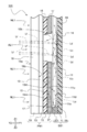
- FIG. 3 is a cross-sectional configuration diagram illustrating the display device 101 according to the first embodiment of the present invention. Note that FIG. 3 schematically shows a part of it for ease of explanation, and does not show the actual size.
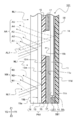
- FIG. 4 is a diagram illustrating the display device 101 according to the first embodiment of the present invention, and is a cross-sectional configuration diagram illustrating an example of an optical path in the display device 101.
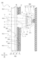
- FIG. 5 is a diagram illustrating the display device 101 according to the first embodiment of the present invention, and is a cross-sectional configuration diagram illustrating an example of an optical path in the display device 101. 4 shows a state where the illumination member SB1 is turned on, and FIG. 5 shows a state where the illumination member SB1 is turned off. 4 and 5 partially omit cross-sectional hatching for ease of explanation.
- the display device 101 includes a display panel PN1 having an illumination part AL1 and a non-illumination part NL1 visually recognized by a user, and an illumination member that illuminates the illumination part AL1.
- the light guide 11 which is SB1 and the light emission source LE1 are included.
- the display panel PN1 according to the first embodiment of the present invention also serves as the front plate of the operation panel device 402 described above.
- the insertion hole 402h and the opening of each operation button are provided. Is also formed.
- FIG. 3 does not show the insertion hole 402h or the opening of each operation button, but shows only the main configuration of the display device 101.
- the display panel PN ⁇ b> 1 includes a translucent base material 19, a smoke layer 13 formed on the back surface 19 b of the base material 19 on the side of the illumination member SB ⁇ b> 1 (Y1 side shown in FIG. 3), and illumination.
- the color layer 15 is formed on the main surface 13m of the smoke layer 13 on the member SB1 side
- the black layer 17 is formed on the main surface 15m of the color layer 15 on the illumination member SB1 side.
- the base material 19 is made of a colorless and translucent polycarbonate synthetic resin, and has a plate-like shape as shown in FIG. 3. One surface of the base material 19, that is, the front surface 19 a is visually recognized by the user.
- polycarbonate resin was used as a synthetic resin material, it is not restricted to this, For example, you may use an acrylic resin, a polyurethane resin, a silicone resin, etc.
- the smoke layer 13 is made of an acrylic synthetic resin having a translucent color with a gray color, and is formed on the entire back surface 19b of the substrate 19 as shown in FIG.
- the smoke layer 13 has a function of diffusing the incident light, uniformly emits the light incident on the smoke layer 13, and blurs the boundary between the illumination part AL1 and the non-illumination part NL1. be able to.
- the smoke layer 13 has a function of adjusting the color tone of transmitted light that passes through the smoke layer 13, and by adjusting the color tone of the smoke layer 13, the color tone of the non-illuminated portion NL1 that is visually recognized by the user. And the color tone of the illumination part AL1 can be brought close to each other.
- the light transmittance in the smoke layer 13 is 1% or more. In particular, in the first embodiment of the present invention, the light transmittance in the smoke layer 13 is about 10%.
- the white coating film 844 (smoke layer) of the prior art example 1 and the smoke layer 913 of the prior art example 2 which are normally set to 1% or less more light can be transmitted through the smoke layer 13. it can.
- the user can visually recognize the display pattern (P01 or P02 shown in FIG. 2) of the illumination unit AL1 brighter.
- the transmittance of the smoke layer 13 is higher than that of the conventional example 1 and the conventional example 2, and thus the luminance of the selected illumination member SB1 is further suppressed. be able to.
- the color layer 15 is made of an acrylic synthetic resin having the same color as that of the smoke layer 13 and having a light shielding property, and is formed on the main surface 13m of the smoke layer 13 as shown in FIG. Further, as shown in FIG. 3, the color layer 15 has a portion that is not formed on the main surface 13m of the smoke layer 13, that is, an opening 15k. Then, as shown in FIG. 4, the irradiation light Lf from the illumination member SB1 passes through the opening 15k, further passes through the smoke layer 13 and the base material 19, and is emitted to the front surface 19a side of the base material 19. Lr is emitted as Lr, and the emitted light Lr is visually recognized by the user.
- the opening 15k forms the illumination part AL1
- the irradiation light Lf from the illumination member SB1 is shielded by the color layer 15 other than the opening 15k, so that the color layer 15 other than the opening 15k is non-illuminated NL1. Is forming.
- the smoke layer 13 is formed on the front side of the color layer 15 that forms the illumination part AL1 and the non-illumination part NL1, the background colors of the illumination part AL1 and the non-illumination part NL1 are made more uniform. can do. For this reason, it is possible to make the boundary between the illumination part AL1 and the non-illumination part NL1 more difficult for the user to see.
- the color of the smoke layer 13 is adjusted so that the color difference between the visible light AA (shown in FIG. 5) visually recognized by the user and the visible light NN (shown in FIG. 5) becomes equal during non-lighting. ing. That is, as shown in FIG. 5, the light that does not pass through the smoke layer 13, the reflected light A1 and the reflected light N1, and the reflected light A2 and the reflected light N2 have the same intensity and color, respectively. Since the light transmitted through the smoke layer 13 and the reflected light (N3, A3, A4, A5) are different from each other, the color difference between the visible light AA and the visible light NN is equalized by adjusting the color of the smoke layer 13. It is trying to become. Specifically, the color of the smoke layer 13 is adjusted so that the light obtained by combining the reflected light A3, the reflected light A4, and the reflected light A5 is equal to the reflected light N3.
- the smoke layer 13 mainly adjusts the hue and saturation.
- the color layer 15 is formed so that the color difference between the visible light AA (shown in FIG. 5) visually recognized by the user and the visible light NN (shown in FIG. 5) becomes equal when not illuminated.
- the color is adjusted. That is, as shown in FIG. 5, the reflected light A1 and the reflected light N1 that reflect the front surface 19a of the base material 19 and the reflected light A2 and the reflected light N2 that reflect the back surface 19b of the base material 19 have the same intensity and color. Although it is a taste light, the other reflected lights (N3, A3, A4, A5) are different from each other.
- the visible light By adjusting the reflected light N3 reflected at the interface between the smoke layer 13 and the color layer 15, the visible light
- the color difference between AA and the visible light NN is made equal.
- the color of the color layer 15 is adjusted so that the light obtained by combining the reflected light A3, the reflected light A4, and the reflected light A5 is equal to the reflected light N3.
- the brightness is mainly adjusted.
- the color tone of the non-illuminated portion NL1 can be brought close to the color tone of the illuminated portion AL1, and a state where the contour of the illuminated portion AL1 is not visually recognized can be realized.
- the black display panel PN1 in which the display pattern P01 and the display pattern P02 are not visually recognized is not visible when not illuminated, and the display pattern P01 or the display pattern P02 is illuminated when illuminated.
- the black display panel PN1 is visually recognized.
- the smoke layer 13 is easily produced by printing a dimming ink in which a pigment, a diffusing material, an acrylic resin, and a solvent are mixed on the entire surface of the back surface 19b of the base material 19 with a screen plate, and then drying and solidifying. It can be carried out.
- the color layer 15 is easily produced by printing a light control ink mixed with a pigment, an acrylic resin and a solvent on the main surface 13m of the smoke layer 13 with a screen plate, followed by drying and solidifying. Can do.
- the black layer 17 is made of an acrylic synthetic resin which is black and has a light shielding property, and is formed on the main surface 15m of the color layer 15 as shown in FIG.
- the black layer 17 reliably blocks the irradiation light Lf from the illumination member SB1. For this reason, at the time of illumination, transmission of the irradiation light Lf to the non-illuminated part NL1 side can be reliably prevented. Further, even when the color layer 15 has a defect such as a pinhole, it is possible to prevent the irradiation light Lf from being transmitted to the non-illuminated portion NL1 side.
- the black layer 17 is easily produced by printing black ink, which is a mixture of carbon powder, acrylic resin and solvent, on the main surface 15m of the color layer 15 with a screen plate, and drying and solidifying. be able to.
- the illumination member SB1 includes a light emitting light source LE1 and a light guide 11 having a light incident portion 11n into which light from the light emitting light source LE1 enters, and the display panel PN1. It is arranged on the back side.
- the light guide 11 has a flat plate shape and uses a light-transmitting polycarbonate synthetic resin as a base material. Further, as shown in FIGS. 3 and 4, the light guide 11 is disposed so as to face the display panel PN1, and is arranged on the rear surface 11d of the light guide 11 opposite to the front surface 11u facing the display panel PN1. The scattering layer 14 is formed at a position corresponding to the illumination part AL1. Moreover, the light guide 11 has a light incident portion 11n that receives light from the light emitting light source LE1 at an end portion thereof. As shown in FIG.
- the light La incident from the light incident portion 11 n is repeatedly reflected at the boundary with air on the front surface 11 u and the rear surface 11 d of the light guide 11 and propagates inside the light guide 11.
- polycarbonate resin was used as a synthetic resin material, it is not restricted to this, For example, you may use an acrylic resin, a polyurethane resin, a silicone resin, etc.
- the scattering layer 14 is made of a crystalline material having a grain boundary that reflects light inside the layer, or a material in which a desired material is mixed to change the light transmission path.
- a crystalline material having a grain boundary that reflects light inside the layer, or a material in which a desired material is mixed to change the light transmission path.
- powders such as titanium dioxide, zirconium dioxide (zirconia), magnesium oxide, and calcium carbonate are used as desired materials.
- a part of the reflected scattered light Ld reaches the opening 15k of the color layer 15 and the irradiation light Lf passes through the smoke layer 13 and the base material 19 and is emitted as radiated light Lr on the front surface 19a side of the base material 19. Radiated.
- the user visually recognizes the display device 101 from the front side (Y2 side shown in FIG. 1), the user can visually recognize the radiated light Lr and confirm the illuminated display pattern P01 and display pattern P02. can do.
- the light-emitting light source LE1 suitably uses a side-emitting LED (Light Emitting Diode), for example, mounted on a printed wiring board 59 and disposed at a position facing the light incident portion 11n as shown in FIG.
- the light emitting surface is arranged in a direction in which light can be incident on the light incident portion 11n.
- the light emitting light source LE1 is disposed on the side surface, and the light from the light emitting light source LE1 is propagated to the light guide 11, so that the display device 101 can be thinned and the light emitting light source LE1 can be used during illumination. Can be efficiently guided to the illumination part AL1.
- the display device 101 according to the present invention forms the smoke layer 13 on the back surface 19b of the base material 19 of the display panel PN1, and thereby the illumination unit AL1.
- the background color of the non-illuminated part NL1 can be made more uniform. For this reason, it is possible to make the boundary between the illumination part AL1 and the non-illumination part NL1 more difficult for the user to see.
- a non-black color layer 15 on the main surface 13m of the smoke layer 13 on the side of the illumination member SB1 reflection at the interface between the smoke layer 13 and the color layer 15 of the non-illuminated part NL1 at the time of non-lighting. The user views the light N3.
- the reflected light N3 at this interface can be adjusted to bring the color tone of the non-illuminated part NL1 visually recognized by the user closer to the color tone of the illuminated part AL1.
- the transmitted light transmitted through the smoke layer 13 can be adjusted to make the color tone of the non-illuminated part NL1 visually recognized by the user closer to the color tone of the illuminated part AL1. .
- the state where the outline of illumination part AL1 is not visually recognized at the time of non-lighting is realizable. Therefore, it is possible to provide the display device 101 in which the display pattern (for example, P01 or P02 shown in FIG. 2) of the illumination unit AL1 is not visually recognized with a simple configuration when not illuminated.
- the light shielding black layer 17 is formed on the main surface 15m of the color layer 15 on the side of the illumination member SB1, the irradiation light Lf from the illumination member SB1 can be reliably shielded by the black layer 17. . For this reason, at the time of illumination, transmission of the irradiation light Lf to the non-illuminated part NL1 side can be reliably prevented. Further, even when the color layer 15 has a defect such as a pinhole, it is possible to prevent the irradiation light Lf from being transmitted to the non-illuminated portion NL1 side. Thereby, at the time of illumination, the difference between the illumination part AL1 and the non-illumination part NL1 can be clarified, and the designability of the applied product can be enhanced.
- the light transmittance of the smoke layer 13 is 1% or more, it is possible to increase the irradiation light Lf that passes through the illumination part AL1. Thereby, at the time of illumination, the user can visually recognize the display pattern (P01 or P02 shown in FIG. 2) of the illumination unit AL1 brighter. Moreover, when illuminating so that the brightness to be visually recognized is constant, the transmittance of the smoke layer 13 is high, so that the luminance of the illuminating member SB1 to be selected can be further reduced, and the display device 101 can save power. It can be carried out.
- the illumination member SB1 includes the light emission source LE1 and the light guide 11 having the light incident portion 11n into which the light from the light emission light source LE1 enters, the light from the light emission light source LE1 is illuminated at the illumination portion AL1. Can be guided efficiently. Thereby, the illumination part AL1 can be illuminated uniformly, and the quality of the applied product can be improved.
- the display device 101 is used in the in-vehicle panel unit 501 as an example.
- the display device 101 is not limited to the in-vehicle device, but is used in other electric devices such as a portable device. You can also.
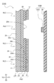
- FIG. 6 is a cross-sectional configuration diagram illustrating the display device 102 according to the second embodiment of the present invention.
- FIG. 7 is a diagram illustrating a display device according to the second embodiment of the present invention, and is a side configuration diagram illustrating an example of an optical path in the display device.
- FIG. 7 shows a state where the illumination member SB2 is lit.
- FIG. 8 is a diagram illustrating a display device 102 according to the second embodiment of the present invention, and is a side configuration diagram illustrating an example of an optical path in the display device 102.
- FIG. 8 shows a state where the illumination member SB2 is turned off. 7 and 8 partially omit cross-sectional hatching for ease of explanation.
- the display apparatus 102 of 2nd Embodiment differs in the structure of illumination member SB2 with respect to 1st Embodiment.
- symbol is attached
- the display device 102 includes a display panel PN2 having an illumination part AL2 and a non-illumination part NL2 visually recognized by a user, and an illumination member that illuminates the illumination part AL2.
- the light guide 21 which is SB2 and the light emitting light source LE2 are included.
- the display panel PN2 includes a translucent base material 29, a smoke layer 23 formed on the back surface 29b of the base material 29 on the side of the illumination member SB2 ⁇ Y1 side shown in FIG. 6), and illumination.
- the color layer 25 is formed on the main surface 23m of the smoke layer 23 on the member SB2 side
- the black layer 17 is formed on the main surface 25m of the color layer 25 on the illumination member SB2 side.
- the base material 29 is made of a colorless and translucent polycarbonate synthetic resin, and has a plate shape as shown in FIG. 6.
- One surface of the base material 29, that is, the front surface 29 a is visually recognized by the user.
- polycarbonate resin was used as a synthetic resin material, it is not restricted to this, For example, you may use an acrylic resin, a polyurethane resin, a silicone resin, etc.
- a silvery color is preferably selected as the color of the base material 29.
- the smoke layer 23 is made of an acrylic synthetic resin having a white color and translucency, and is formed on the entire back surface 29b of the substrate 29 as shown in FIG.
- the smoke layer 23 has a function of diffusing the incident light, uniformly emits the light incident on the smoke layer 23, and blurs the boundary between the illumination part AL2 and the non-illumination part NL2. be able to. Further, the smoke layer 23 has a function of adjusting the color tone of the transmitted light that passes through the smoke layer 23. By adjusting the color tone of the smoke layer 23, the color tone of the non-illuminated portion NL2 that is visually recognized by the user. And the color tone of the illumination part AL2.
- the light transmittance of the smoke layer 23 is 1% or more. In particular, in the second embodiment of the present invention, the light transmittance of the smoke layer 23 is about 7%.
- the white coating film 844 (smoke layer) of the prior art example 1 and the smoke layer 913 of the prior art example 2 which are normally set to 1% or less, more light is transmitted through the smoke layer 23. it can.
- the user can visually recognize the display pattern of the illumination part AL2 brighter.
- the luminance of the selected illuminating member SB2 is further suppressed. be able to.
- the color layer 25 is made of a polyester-based synthetic resin having a silver color and having a light shielding property, and is formed on the main surface 23m of the smoke layer 23 as shown in FIG. Further, as shown in FIG. 6, the color layer 25 has a portion that is not formed on the main surface 23m of the smoke layer 23, that is, an opening 25k. Then, as shown in FIG. 7, the irradiation light Lf from the illumination member SB2 passes through the opening 25k, further passes through the smoke layer 23 and the base material 29, and is emitted to the front surface 29a side of the base material 29. Lr is emitted as Lr, and the emitted light Lr is visually recognized by the user.
- the opening 25k forms the illumination part AL2
- the irradiation light Lf from the illumination member SB2 is shielded by the color layer 25 other than the opening 25k, so that the color layer 25 other than the opening 25k becomes the non-illumination part NL2. Is forming.
- the smoke layer 23 is formed on the front side of the color layer 25 that forms the illumination part AL2 and the non-illumination part NL2, the background colors of the illumination part AL2 and the non-illumination part NL2 are made more uniform. can do. For this reason, it can be made harder for the user to see the boundary between the illumination part AL2 and the non-illumination part NL2.
- the color of the smoke layer 23 is adjusted so that the color difference between the visible light AA (shown in FIG. 8) visually recognized by the user and the visible light NN (shown in FIG. 8) becomes equal when not illuminated. ing. That is, as shown in FIG. 8, the light that does not pass through the smoke layer 23, the reflected light A6 and the reflected light N6, and the reflected light A7 and the reflected light N7 have the same intensity and color, respectively. Since the light transmitted through the smoke layer 23 and the reflected light (N8, A8, A9, A10, A11) are different from each other, the color difference between the visible light AA and the visible light NN is adjusted by adjusting the color of the smoke layer 23. It is trying to be equivalent.
- the color of the smoke layer 23 is adjusted so that the light obtained by combining the reflected light A8, the reflected light A9, the reflected light A10, and the reflected light A11 is equal to the reflected light N8. Yes.
- the smoke layer 23 mainly adjusts the hue and saturation.
- the color layer 25 is formed so that the color difference between the visible light AA (shown in FIG. 8) visually recognized by the user and the visible light NN (shown in FIG. 8) becomes equal when not illuminated.
- the color is adjusted. That is, as shown in FIG. 8, the reflected light A6 and the reflected light N6 that reflect the front surface 29a of the base material 29, and the reflected light A7 and the reflected light N7 that reflect the back surface 29b of the base material 29 have the same intensity and color.
- the other reflected light (N8, A8, A9, A10, A11) is different, so by adjusting the reflected light N6 reflected at the interface between the smoke layer 23 and the color layer 25,
- the color difference between the visual light AA and the visual light NN is made equal.
- the color of the color layer 25 is adjusted so that the light obtained by combining the reflected light A8, the reflected light A9, the reflected light A10, and the reflected light A11 is equal to the reflected light N8. Yes.
- the brightness is mainly adjusted.
- the color tone of the non-illuminated portion NL2 and the color tone of the illuminated portion AL2 can be brought close to each other, and a state where the outline of the illuminated portion AL2 is not visually recognized can be realized.
- the white display panel PN2 in which the display pattern is not visually recognized when not illuminated and the white display panel PN2 in which the display pattern is visually recognized when illuminated. Is visible.
- the smoke layer 23 is produced by printing a dimming ink in which a pigment, a diffusing material, an acrylic resin, and a solvent are mixed on the entire surface of the back surface 29b of the base material 29 with a roll coater, followed by drying and solidifying. It can be done easily.
- the color layer 25 is easily produced by printing a light control ink mixed with a pigment, an acrylic resin, and a solvent on the main surface 23m of the smoke layer 23 with a screen plate, followed by drying and solidifying. Can do.
- the illumination member SB2 includes a light source LE2, a light guide 21 having a light incident portion 21n into which light from the light source LE2 enters, a light guide 21 and a display panel PN2. And a scattering member 24 disposed therebetween, and is disposed on the back side of the display panel PN2.
- the light guide 21 has a block shape and uses a transparent acrylic synthetic resin as a base material.
- the light guide 21 is disposed so as to face the display panel PN2, and between the display panel PN2 and the light guide 21, a position corresponding to the illumination unit AL2 is provided.
- a scattering member 24 is provided.
- the light guide 21 has a light incident portion 21n that receives light from the light emitting light source LE2 at an end portion thereof. As shown in FIG. 7, the light La incident from the light incident portion 21 n propagates inside the light guide 21, and the light Lb propagated through the light guide 21 enters the scattering member 24.
- the acrylic resin was used as a synthetic resin material, it is not restricted to this, For example, a polyurethane resin, a polycarbonate resin, a silicone resin, etc. may be used.
- the scattering member 24 is affixed to the light guide 21 on the side facing the display panel PN2, using a film material having a property of reflecting and scattering light inside the layer.
- the light Lb incident on the scattering member 24 is reflected and scattered, and is emitted to the front side (Y2 side shown in FIG. 7) as irradiation light Lf.
- the irradiation light Lf that reaches part of the opening 25k of the color layer 25 through a part of the irradiation light Lf passes through the smoke layer 23 and the base material 29, and is emitted as radiated light Lr on the front surface 19a side of the base material 19. Is done.
- the user can visually recognize the emitted light Lr and can confirm the illuminated display pattern.
- the light-emitting light source LE2 suitably uses a top-emitting LED (Light-Emitting-Diode), for example, mounted on a printed wiring board 59 and disposed at a position facing the light incident portion 21n as shown in FIG.
- the light emitting surface is arranged in a direction in which light can be incident on the light incident portion 21n.
- the smoke layer 23 is formed on the back surface 29b of the base material 29 of the display panel PN2, so that the background of the illumination part AL2 and the non-illumination part NL2 can be obtained.
- the color can be made more uniform. For this reason, it can be made harder for the user to see the boundary between the illumination part AL2 and the non-illumination part NL2.
- a non-black color layer 25 on the main surface 23m of the smoke layer 23 on the side of the illumination member SB2, reflection at the interface between the smoke layer 23 and the color layer 25 of the non-illuminated part NL2 at the time of non-lighting. The user views the light N3.
- the reflected light N3 at this interface can be adjusted to bring the color tone of the non-illuminated part NL2 visually recognized by the user closer to the color tone of the illuminated part AL2.
- the transmitted light transmitted through the smoke layer 23 can be adjusted, so that the color tone of the non-illuminated part NL2 visually recognized by the user can be made closer to the color tone of the illuminated part AL2. .
- the state where the outline of illumination part AL2 is not visually recognized at the time of non-lighting is realizable. Accordingly, it is possible to provide the display device 102 in which the display pattern of the illumination unit AL2 is not visually recognized with a simple configuration when not illuminated.
- the light transmittance of the smoke layer 23 is 1% or more, it is possible to increase the irradiation light Lf that passes through the illumination part AL2. Thereby, at the time of illumination, the user can visually recognize the display pattern of the illumination part AL2 more brightly.
- the luminance of the smoke layer 23 is high, so that the luminance of the illuminating member SB2 to be selected can be further reduced, and power saving of the display device 102 can be achieved. It can be carried out.
- the illumination member SB2 includes the light emission source LE2 and the light guide 21 having the light incident portion 21n into which the light from the light emission light source LE2 enters, the light from the light emission light source LE2 is illuminated at the illumination portion AL2 during illumination. Can be guided efficiently. Thereby, the illumination part AL2 can be illuminated uniformly, and the quality of the applied product can be improved.
- FIG. 9 is a diagram illustrating a display device according to a first modification of the embodiment of the present invention, and is a cross-sectional configuration diagram illustrating a display panel CPN.
- FIG. 10 is a cross-sectional configuration diagram illustrating a display device C103 according to the second modification of the second embodiment of the present invention.
- the black display panel PN1 is used in the first embodiment, and the white display panel PN2 is used in the second embodiment.
- the display panel is not limited to black and white systems. Other color systems may be used.
- a colorless and translucent substrate CR9 a white translucent smoke layer CR3, a silver-based light-shielding color layer CR5, and a black light-shielding property.
- These black layers CR7 are preferably combined.
- the light guide 21 is preferably provided. However, as illustrated in FIG. 10, the light guide 21 is not provided, and the light emission that directly illuminates the illumination unit AL2 as the illumination member CSB.
- the structure which has the light source CLE may be sufficient. Thereby, at the time of illumination, the illumination part AL2 can be directly illuminated, and the display pattern can be displayed more and more brightly.
- the light guide 21 is preferably provided.
- the light guide 21 is not provided, and a light-transmitting device, such as a membrane, is provided between the display panel PN2 and the light emitting light source LE2.
- a switch device or the like may be provided.
- the black layer 17 is preferably provided. However, the black layer 17 may be omitted.
Landscapes
- Physics & Mathematics (AREA)
- General Physics & Mathematics (AREA)
- Engineering & Computer Science (AREA)
- Theoretical Computer Science (AREA)
- Optics & Photonics (AREA)
- Illuminated Signs And Luminous Advertising (AREA)
- Planar Illumination Modules (AREA)
Abstract
Description
図1は、本発明の第1実施形態の表示装置101を説明する図であって、表示装置101を備えた車載用パネルユニット501の外観を示す斜視図である。図2は、本発明の第1実施形態の表示装置101を説明する構成図であって、図2(a)は、「オーディオ操作モード」における表示装置101の正面図であり、図2(b)は、「エアコン操作モード」における表示装置101の正面図である。なお、図1では、図2に示す表示パターンP01及び表示パターンP02を省略している。
図6は、本発明の第2実施形態の表示装置102を説明する断面構成図である。図7は、本発明の第2実施形態の表示装置を説明する図であって、表示装置における光路の一例を示した側面構成図である。図7は、照光部材SB2が点灯している状態を示している。図8は、本発明の第2実施形態の表示装置102を説明する図であって、表示装置102における光路の一例を示した側面構成図である。図8は、照光部材SB2が消灯している状態を示している。なお、図7及び図8は、説明を容易にするため、断面のハッチングを一部省略している。また、第2実施形態の表示装置102は、第1実施形態に対し、照光部材SB2の構成が異なる。なお、第1実施形態と同一構成については、同一符号を付して詳細な説明は省略する。
上記第1実施形態では黒色系の表示パネルPN1にし、上記第2実施形態では白色系の表示パネルPN2にしたが、黒色系及び白色系に限るものではなく、例えば、赤色系や青色系等の他の色系でも良い。例えば、図9に示す赤色系の表示パネルCPNの場合、無色で透光性の基材CR9と白色系で透光性のスモーク層CR3と銀色系で遮光性のカラー層CR5と黒色で遮光性のブラック層CR7を組み合わせて構成すると良い。更に、図9に示すように、スモーク層CR3とカラー層CR5との間に、白色系で透光性のホワイト層CR4を設けると、赤色の彩度を高めることができ、より好適である。
上記第2実施形態では、ライトガイド21を設けるように好適に構成したが、図10に示すように、ライトガイド21を設けずに、照光部材CSBとして、照光部AL2を直接照明している発光光源CLEを有している構成でも良い。これにより、照光時において、照光部AL2を直接照明でき、表示パターンをより一層益々明るく表示することができる。
上記第2実施形態では、ライトガイド21を設けるように好適に構成したが、ライトガイド21を設けずに、表示パネルPN2と発光光源LE2との間に、透光性を有した装置、例えばメンブレンスイッチ装置等が配設されていても良い。
上記実施形態では、ブラック層17を設けるように好適に構成したが、ブラック層17を設けない構成でも良い。
11n、21n 入光部
13、23、CR3 スモーク層
13m、23m 主面
15、25、CR5 カラー層
15k、25k 開口部
15m、25m 主面
17、CR7 ブラック層
19、29、CR9 基材
19b、29b 背面
101、102、C103 表示装置
AL1、AL2、CAL 照光部
LE1、LE2、CLE 発光光源
NL1、NL2 非照光部
PN1、PN2、CPN 表示パネル
SB1、SB2、CSB 照光部材
Claims (5)
- 照光部と非照光部とを有する表示パネルと、該表示パネルの背面側に配置され、前記照光部を照明する照光部材と、から構成された表示装置であって、
前記表示パネルは、透光性の基材と、該基材の前記照光部材側の背面に形成された透光性のスモーク層と、を有し、
前記スモーク層の前記照光部材側の主面には、遮光性のカラー層が形成され、
前記カラー層は、前記照光部を形成するための開口部を有していることを特徴とする表示装置。 - 前記カラー層の前記照光部材側の主面には、遮光性のブラック層が形成されていることを特徴とする請求項1に記載の表示装置。
- 前記スモーク層の透光率が1%以上であることを特徴とする請求項1に記載の表示装置。
- 前記照光部材は、前記照光部を直接照明している発光光源を有していることを特徴とする請求項1に記載の表示装置。
- 前記照光部材は、発光光源と、該発光光源からの光が入光する入光部を有するライトガイドと、を備えていることを特徴とする請求項1に記載の表示装置。
Priority Applications (4)
| Application Number | Priority Date | Filing Date | Title |
|---|---|---|---|
| JP2015501515A JPWO2014129577A1 (ja) | 2013-02-22 | 2014-02-21 | 表示装置 |
| CN201480009828.1A CN105074858A (zh) | 2013-02-22 | 2014-02-21 | 显示装置 |
| EP14753591.8A EP2960916A4 (en) | 2013-02-22 | 2014-02-21 | DISPLAY DEVICE |
| US14/831,350 US20150354759A1 (en) | 2013-02-22 | 2015-08-20 | Display device |
Applications Claiming Priority (2)
| Application Number | Priority Date | Filing Date | Title |
|---|---|---|---|
| JP2013-033501 | 2013-02-22 | ||
| JP2013033501 | 2013-02-22 |
Related Child Applications (1)
| Application Number | Title | Priority Date | Filing Date |
|---|---|---|---|
| US14/831,350 Continuation US20150354759A1 (en) | 2013-02-22 | 2015-08-20 | Display device |
Publications (1)
| Publication Number | Publication Date |
|---|---|
| WO2014129577A1 true WO2014129577A1 (ja) | 2014-08-28 |
Family
ID=51391358
Family Applications (1)
| Application Number | Title | Priority Date | Filing Date |
|---|---|---|---|
| PCT/JP2014/054131 Ceased WO2014129577A1 (ja) | 2013-02-22 | 2014-02-21 | 表示装置 |
Country Status (5)
| Country | Link |
|---|---|
| US (1) | US20150354759A1 (ja) |
| EP (1) | EP2960916A4 (ja) |
| JP (1) | JPWO2014129577A1 (ja) |
| CN (1) | CN105074858A (ja) |
| WO (1) | WO2014129577A1 (ja) |
Cited By (9)
| Publication number | Priority date | Publication date | Assignee | Title |
|---|---|---|---|---|
| JP2016171009A (ja) * | 2015-03-13 | 2016-09-23 | シャープ株式会社 | 操作パネル及びそれを備えた床置き型電気機器 |
| JP2016177871A (ja) * | 2015-03-18 | 2016-10-06 | シロキ工業株式会社 | 光装飾具 |
| JP2017090814A (ja) * | 2015-11-16 | 2017-05-25 | 株式会社デンソー | 表示装置 |
| JP2019144280A (ja) * | 2018-02-15 | 2019-08-29 | 株式会社ミマキエンジニアリング | 多層印刷物 |
| JP2020132135A (ja) * | 2019-02-25 | 2020-08-31 | 現代自動車株式会社Hyundai Motor Company | 車両用タッチ式ボタン |
| JP2021089565A (ja) * | 2019-12-04 | 2021-06-10 | キヤノン株式会社 | 外装カバー及び読取装置 |
| JP2022028359A (ja) * | 2020-08-03 | 2022-02-16 | 株式会社東海理化電機製作所 | パネル装置 |
| DE112021004063T5 (de) | 2020-07-31 | 2023-06-01 | Alps Alpine Co., Ltd. | Anzeigevorrichtung |
| CN117218976A (zh) * | 2022-06-09 | 2023-12-12 | 卡西欧计算机株式会社 | 面板部件以及电子设备 |
Families Citing this family (3)
| Publication number | Priority date | Publication date | Assignee | Title |
|---|---|---|---|---|
| JP7203366B2 (ja) * | 2017-03-16 | 2023-01-13 | パナソニックIpマネジメント株式会社 | 表示装置 |
| CN114981869B (zh) * | 2020-01-21 | 2024-03-01 | 三菱化学株式会社 | 显示设备、车辆内外装饰构件、照明灯用灯和显示用招牌 |
| CN112485941B (zh) * | 2020-12-03 | 2022-03-08 | 惠州市华星光电技术有限公司 | 一种液晶显示面板及其制备方法 |
Citations (6)
| Publication number | Priority date | Publication date | Assignee | Title |
|---|---|---|---|---|
| JP2008268801A (ja) * | 2007-04-25 | 2008-11-06 | Calsonic Kansei Corp | 表示装置 |
| JP2009092993A (ja) * | 2007-10-10 | 2009-04-30 | Omron Corp | 表示フィルタ、及び表示フィルタを有する表示モジュール |
| JP2009123602A (ja) * | 2007-11-16 | 2009-06-04 | Toyoda Gosei Co Ltd | 情報表示機能付きスイッチ及びその製造方法 |
| JP2010064550A (ja) | 2008-09-09 | 2010-03-25 | Alps Electric Co Ltd | 車載用操作パネル装置 |
| JP2011258382A (ja) * | 2010-06-08 | 2011-12-22 | Canon Inc | 操作装置および画像読取装置 |
| JP2012148599A (ja) | 2011-01-17 | 2012-08-09 | Suzuki Motor Corp | 表示装置 |
Family Cites Families (4)
| Publication number | Priority date | Publication date | Assignee | Title |
|---|---|---|---|---|
| US4965950A (en) * | 1987-03-23 | 1990-10-30 | Koito Manufacturing Co., Ltd. | Display device for automotive mark plate |
| US8113695B2 (en) * | 2005-02-04 | 2012-02-14 | Adac Plastics, Inc. | Trim component with concealed indicium |
| JP2007071691A (ja) * | 2005-09-07 | 2007-03-22 | Yazaki Corp | 車載計器 |
| JP4258541B2 (ja) * | 2006-09-08 | 2009-04-30 | パナソニック株式会社 | 操作表示装置 |
-
2014
- 2014-02-21 WO PCT/JP2014/054131 patent/WO2014129577A1/ja not_active Ceased
- 2014-02-21 JP JP2015501515A patent/JPWO2014129577A1/ja active Pending
- 2014-02-21 CN CN201480009828.1A patent/CN105074858A/zh active Pending
- 2014-02-21 EP EP14753591.8A patent/EP2960916A4/en not_active Withdrawn
-
2015
- 2015-08-20 US US14/831,350 patent/US20150354759A1/en not_active Abandoned
Patent Citations (6)
| Publication number | Priority date | Publication date | Assignee | Title |
|---|---|---|---|---|
| JP2008268801A (ja) * | 2007-04-25 | 2008-11-06 | Calsonic Kansei Corp | 表示装置 |
| JP2009092993A (ja) * | 2007-10-10 | 2009-04-30 | Omron Corp | 表示フィルタ、及び表示フィルタを有する表示モジュール |
| JP2009123602A (ja) * | 2007-11-16 | 2009-06-04 | Toyoda Gosei Co Ltd | 情報表示機能付きスイッチ及びその製造方法 |
| JP2010064550A (ja) | 2008-09-09 | 2010-03-25 | Alps Electric Co Ltd | 車載用操作パネル装置 |
| JP2011258382A (ja) * | 2010-06-08 | 2011-12-22 | Canon Inc | 操作装置および画像読取装置 |
| JP2012148599A (ja) | 2011-01-17 | 2012-08-09 | Suzuki Motor Corp | 表示装置 |
Non-Patent Citations (1)
| Title |
|---|
| See also references of EP2960916A4 |
Cited By (18)
| Publication number | Priority date | Publication date | Assignee | Title |
|---|---|---|---|---|
| JP2016171009A (ja) * | 2015-03-13 | 2016-09-23 | シャープ株式会社 | 操作パネル及びそれを備えた床置き型電気機器 |
| JP2016177871A (ja) * | 2015-03-18 | 2016-10-06 | シロキ工業株式会社 | 光装飾具 |
| JP2017090814A (ja) * | 2015-11-16 | 2017-05-25 | 株式会社デンソー | 表示装置 |
| WO2017085960A1 (ja) * | 2015-11-16 | 2017-05-26 | 株式会社デンソー | 表示装置 |
| CN107710314A (zh) * | 2015-11-16 | 2018-02-16 | 株式会社电装 | 显示装置 |
| CN107710314B (zh) * | 2015-11-16 | 2020-06-26 | 株式会社电装 | 显示装置 |
| JP2019144280A (ja) * | 2018-02-15 | 2019-08-29 | 株式会社ミマキエンジニアリング | 多層印刷物 |
| JP7452987B2 (ja) | 2019-02-25 | 2024-03-19 | 現代自動車株式会社 | 車両用タッチ式ボタン |
| JP2020132135A (ja) * | 2019-02-25 | 2020-08-31 | 現代自動車株式会社Hyundai Motor Company | 車両用タッチ式ボタン |
| JP2021089565A (ja) * | 2019-12-04 | 2021-06-10 | キヤノン株式会社 | 外装カバー及び読取装置 |
| JP7401276B2 (ja) | 2019-12-04 | 2023-12-19 | キヤノン株式会社 | 外装カバー及び読取装置 |
| DE112021004063T5 (de) | 2020-07-31 | 2023-06-01 | Alps Alpine Co., Ltd. | Anzeigevorrichtung |
| DE112021004063B4 (de) | 2020-07-31 | 2025-02-27 | Alps Alpine Co., Ltd. | Anzeigevorrichtung |
| JP2022028359A (ja) * | 2020-08-03 | 2022-02-16 | 株式会社東海理化電機製作所 | パネル装置 |
| CN117218976A (zh) * | 2022-06-09 | 2023-12-12 | 卡西欧计算机株式会社 | 面板部件以及电子设备 |
| JP2023180403A (ja) * | 2022-06-09 | 2023-12-21 | カシオ計算機株式会社 | パネル部材及び電子機器 |
| JP7563423B2 (ja) | 2022-06-09 | 2024-10-08 | カシオ計算機株式会社 | パネル部材及び電子機器 |
| US12494187B2 (en) | 2022-06-09 | 2025-12-09 | Casio Computer Co., Ltd. | Panel and electronic equipment |
Also Published As
| Publication number | Publication date |
|---|---|
| US20150354759A1 (en) | 2015-12-10 |
| EP2960916A1 (en) | 2015-12-30 |
| CN105074858A (zh) | 2015-11-18 |
| EP2960916A4 (en) | 2016-08-24 |
| JPWO2014129577A1 (ja) | 2017-02-02 |
Similar Documents
| Publication | Publication Date | Title |
|---|---|---|
| WO2014129577A1 (ja) | 表示装置 | |
| US8783884B2 (en) | Display device for displaying two graphics | |
| US7802908B2 (en) | Light guide module and a display device with the light guide module | |
| JP7281652B2 (ja) | 表示装置 | |
| CN105992473A (zh) | 可出现光纹图案的电子装置 | |
| US10618408B2 (en) | Display panel | |
| JP7117636B2 (ja) | 照明装置 | |
| CN108454533A (zh) | 车辆用装饰部件 | |
| JP4432911B2 (ja) | 装飾体及び該装飾体を蓋部とした収容箱 | |
| JP2006208660A (ja) | 表示装置 | |
| US11721248B2 (en) | Trim element comprising a main display surface and a peripheral display surface | |
| JP2006322968A (ja) | 表示装置 | |
| JP2018080954A (ja) | 表示装置 | |
| CN102265367A (zh) | 用于控制元件或显示装置的帽 | |
| JP2019056735A (ja) | 表示装置 | |
| JP2007101847A (ja) | 表示装置 | |
| JP2005338499A (ja) | 表示部材及びパネル表示ユニット | |
| JP5196661B2 (ja) | ライトガイドおよびそれを用いた押釦スイッチ用部材 | |
| JP3182109U (ja) | 照光表示装置 | |
| WO2023166976A1 (ja) | 表示装置 | |
| JP2016225234A (ja) | 操作装置 | |
| JP5822740B2 (ja) | 面光源装置 | |
| US20260001480A1 (en) | Lighting Assembly | |
| JP2018190668A (ja) | 表示装置 | |
| JP2004341099A (ja) | 発光表示装置 |
Legal Events
| Date | Code | Title | Description |
|---|---|---|---|
| WWE | Wipo information: entry into national phase |
Ref document number: 201480009828.1 Country of ref document: CN |
|
| 121 | Ep: the epo has been informed by wipo that ep was designated in this application |
Ref document number: 14753591 Country of ref document: EP Kind code of ref document: A1 |
|
| WWE | Wipo information: entry into national phase |
Ref document number: 2014753591 Country of ref document: EP |
|
| ENP | Entry into the national phase |
Ref document number: 2015501515 Country of ref document: JP Kind code of ref document: A |
|
| NENP | Non-entry into the national phase |
Ref country code: DE |