WO2014132763A1 - 光ファイバおよび光伝送路 - Google Patents
光ファイバおよび光伝送路 Download PDFInfo
- Publication number
- WO2014132763A1 WO2014132763A1 PCT/JP2014/052693 JP2014052693W WO2014132763A1 WO 2014132763 A1 WO2014132763 A1 WO 2014132763A1 JP 2014052693 W JP2014052693 W JP 2014052693W WO 2014132763 A1 WO2014132763 A1 WO 2014132763A1
- Authority
- WO
- WIPO (PCT)
- Prior art keywords
- optical fiber
- mode dispersion
- mode
- refractive index
- optical
- Prior art date
- Legal status (The legal status is an assumption and is not a legal conclusion. Google has not performed a legal analysis and makes no representation as to the accuracy of the status listed.)
- Ceased
Links
Images


Classifications
-
- G—PHYSICS
- G02—OPTICS
- G02B—OPTICAL ELEMENTS, SYSTEMS OR APPARATUS
- G02B6/00—Light guides; Structural details of arrangements comprising light guides and other optical elements, e.g. couplings
- G02B6/02—Optical fibres with cladding with or without a coating
- G02B6/02047—Dual mode fibre
-
- G—PHYSICS
- G02—OPTICS
- G02B—OPTICAL ELEMENTS, SYSTEMS OR APPARATUS
- G02B6/00—Light guides; Structural details of arrangements comprising light guides and other optical elements, e.g. couplings
- G02B6/02—Optical fibres with cladding with or without a coating
- G02B6/02214—Optical fibres with cladding with or without a coating tailored to obtain the desired dispersion, e.g. dispersion shifted, dispersion flattened
- G02B6/02219—Characterised by the wavelength dispersion properties in the silica low loss window around 1550 nm, i.e. S, C, L and U bands from 1460-1675 nm
- G02B6/02228—Dispersion flattened fibres, i.e. having a low dispersion variation over an extended wavelength range
- G02B6/02238—Low dispersion slope fibres
-
- G—PHYSICS
- G02—OPTICS
- G02B—OPTICAL ELEMENTS, SYSTEMS OR APPARATUS
- G02B6/00—Light guides; Structural details of arrangements comprising light guides and other optical elements, e.g. couplings
- G02B6/02—Optical fibres with cladding with or without a coating
- G02B6/028—Optical fibres with cladding with or without a coating with core or cladding having graded refractive index
- G02B6/0281—Graded index region forming part of the central core segment, e.g. alpha profile, triangular, trapezoidal core
-
- G—PHYSICS
- G02—OPTICS
- G02B—OPTICAL ELEMENTS, SYSTEMS OR APPARATUS
- G02B6/00—Light guides; Structural details of arrangements comprising light guides and other optical elements, e.g. couplings
- G02B6/02—Optical fibres with cladding with or without a coating
- G02B6/036—Optical fibres with cladding with or without a coating core or cladding comprising multiple layers
- G02B6/03616—Optical fibres characterised both by the number of different refractive index layers around the central core segment, i.e. around the innermost high index core layer, and their relative refractive index difference
- G02B6/03622—Optical fibres characterised both by the number of different refractive index layers around the central core segment, i.e. around the innermost high index core layer, and their relative refractive index difference having 2 layers only
- G02B6/03627—Optical fibres characterised both by the number of different refractive index layers around the central core segment, i.e. around the innermost high index core layer, and their relative refractive index difference having 2 layers only arranged - +
Definitions
- the present invention relates to an optical fiber and an optical transmission line.
- optical information communication As the amount of communication increases, the transmission capacity required for optical fibers as transmission media has also increased. In particular, such a requirement is remarkable in an optical fiber for long-distance transmission by a WDM (wavelength division division) system.
- WDM wavelength division division division
- FMF Frew-Mode Fiber
- MDM Mode Division Multiplexing
- mode dispersion is unavoidable in FMF.
- Mode dispersion causes a reduction in transmission capacity proportional to the transmission distance. Therefore, it is important to suppress mode dispersion in order to realize a large-capacity multimode fiber that can withstand long-distance transmission.
- MIMO Multiple-Input-Multiple-Output
- FMF Multiple-Input-Multiple-Output
- MDM transmission FMF with small mode dispersion is required.
- MDM transmission is assumed to be used in combination with WDM transmission, it is necessary to reduce mode dispersion over a wide wavelength band.
- Non-Patent Documents 1 and 2 listed below provide a wider wavelength band by connecting two or more two-mode fibers, each of which has a different mode dispersion code and a different inclination code with respect to the mode dispersion wavelength.
- a technique for reducing the mode dispersion is disclosed.
- Non-Patent Document 1 proposes an optical transmission line in which a two-mode fiber having a structure in which a graded index core is provided with a trench structure and a two-mode fiber having a structure having only a graded index core are connected. It has been shown that mode dispersion of several ps / km or less can be achieved in C + L-band, which is a wavelength band for optical communication, using the optical transmission line.
- Non-Patent Document 2 proposes a two-mode optical fiber having a step-like refractive index distribution, and uses an optical transmission line to which four optical fibers with adjusted parameters are connected. It is said that mode dispersion of several ps / km or less can be achieved in -band.
- Japanese Patent Publication Japanese Patent Laid-Open No. 2006-222102 (published on August 24, 2006)”
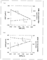
- FIG. 18 is a graph showing the mode dispersion characteristics of a conventional optical fiber (the x axis represents wavelength and the y axis represents mode dispersion). As shown in FIG.
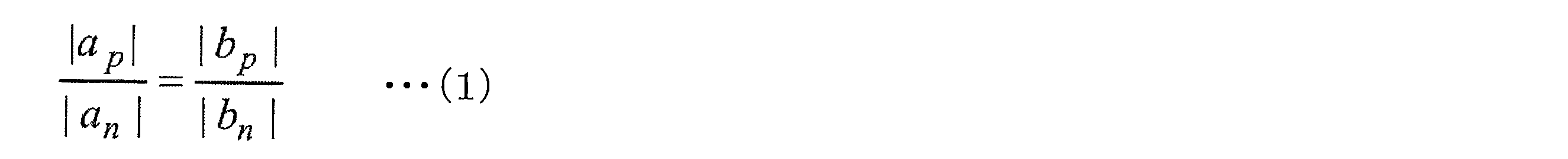
- the mode dispersion ⁇ is insensitive to the variation of the core radius while the inclination with respect to the wavelength ⁇ is insensitive to the variation of the core radius, so the core radius varies. Then, the relationship of the following formula (1) is greatly broken. Therefore, the problem of realizing an optical transmission line that can sufficiently compensate mode dispersion over a wide wavelength band remains unsolved.
- the present invention has been made on the basis of the inventors' further knowledge in view of the above problems, and an object thereof is to provide an optical fiber and an optical fiber capable of sufficiently compensating mode dispersion over a wide wavelength band. It is to realize a transmission line.
- an optical fiber is a two-mode optical fiber that propagates an LP01 mode component and an LP11 mode component included in signal light, and in a predetermined wavelength band,
- the mode dispersion ⁇ defined by the following formula (2) is constant.
- vg11 represents the group velocity of the LP11 mode component
- vg01 represents the group velocity of the LP01 mode component.
- an optical fiber and an optical transmission line capable of sufficiently compensating mode dispersion over a wide wavelength band can be realized.
- FIG. 1 shows a configuration of an optical transmission line according to an embodiment of the present invention. It is a graph which shows the mode dispersion characteristic of the optical fiber which concerns on this embodiment. It is sectional drawing and the side view which show the structure of the optical fiber which concerns on this embodiment. It is a graph which shows the refractive index distribution of the optical fiber which concerns on this embodiment. It is a graph which shows the relationship between parameter Rd and a mode dispersion characteristic regarding the optical fiber which concerns on this embodiment. It is a graph which shows the relationship between parameter Ra and a mode dispersion characteristic regarding the optical fiber which concerns on this embodiment. It is a graph which shows the relationship between parameter (alpha) and a mode dispersion characteristic regarding the optical fiber which concerns on this embodiment.
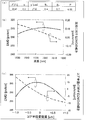
- FIG. (A) shows the setting value of each parameter which prescribes
- FIG. (B) is a graph which shows the mode dispersion characteristic of the optical fiber which concerns on Example 1.
- FIG. (C) is a graph which shows the relationship between the variation
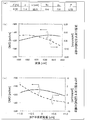
- FIG. (A) shows the setting value of each parameter which prescribes
- FIG. (B) is a graph showing the mode dispersion characteristics of the optical fiber according to Example 2.
- FIG. (C) is a graph which shows the relationship between the fluctuation amount of a core radius, and a mode dispersion characteristic regarding the optical fiber which concerns on Example 2.
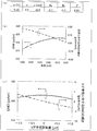
- FIG. (A) shows the setting value of each parameter which prescribes
- FIG. (B) is a graph which shows the mode dispersion characteristic of the optical fiber which concerns on Example 3.
- FIG. (C) is a graph which shows the relationship between the fluctuation amount of a core radius, and a mode dispersion characteristic regarding the optical fiber which concerns on Example 3.
- FIG. (A) shows the setting value of each parameter which prescribes
- FIG. (B) is a graph showing the mode dispersion characteristics of the optical fiber according to Example 4.
- FIG. (C) is a graph which shows the relationship between the fluctuation
- FIG. (A) shows the setting value of each parameter which prescribes
- FIG. (B) is a graph showing mode dispersion characteristics of the optical fiber according to Example 5.
- (C) is a graph showing the relationship between the fluctuation amount of the core radius and the mode dispersion characteristic for the optical fiber according to Example 5.
- FIG. (B) is a graph showing the mode dispersion characteristic of the optical transmission line in Example 6.
- the set value of each parameter that defines the refractive index distribution in the optical fiber of this comparative example is shown. It is a graph which shows the mode dispersion characteristic of the optical fiber which concerns on this comparative example. It is a graph which shows the relationship between the variation
- the mode dispersion ⁇ may be represented as DMD (Differential Modal Group Delay).
- FIG. 1 shows a configuration of optical transmission lines F and F ′ according to the present embodiment.
- the optical transmission lines F and F ′ are each configured to include at least two optical fibers Fp and Fn.
- the optical fiber Fp is a two-mode optical fiber having a positive mode dispersion ⁇ p
- the optical fiber Fn is a two-mode optical fiber having a negative mode dispersion ⁇ n.
- the mode dispersions ⁇ p and ⁇ n are both defined by the above equation (2).
- FIG. 1A shows a configuration example of an optical transmission line F in which an optical fiber Fp having a positive mode dispersion ⁇ p is arranged on the input side and an optical fiber Fn having a negative mode dispersion ⁇ n is arranged on the output side. ing.
- Ln it is possible to sufficiently compensate for mode dispersion in the optical transmission line F and realize an optical transmission line F in which mode dispersion hardly occurs.
- the optical fibers Fp and Fn those whose mode dispersion characteristics do not depend on the wavelength ⁇ (see FIG. 2) are used.
- the lengths of the optical fibers Fp and Fn so as to compensate for the dispersion, as a result, the mode dispersion can be sufficiently compensated over the entire desired wavelength band.
- FIG. 1B shows a configuration example of an optical transmission line F ′ in which an optical fiber Fn having a negative mode dispersion ⁇ n is arranged on the input side, and an optical fiber Fp having a positive mode dispersion ⁇ p is arranged on the output side.
- the time required for the LP01 mode component to propagate through the optical fiber Fn is longer by ⁇ p ⁇ Lp than the time required for the LP11 mode component to propagate through the optical fiber Fn. Therefore, the LP01 mode component is delayed by ⁇ n ⁇ Ln in the process of propagating through the optical fiber Fn.
- the time required for the LP01 mode component to propagate through the optical fiber Fp is shorter by ⁇ p ⁇ Lp than the time required for the LP11 mode component to propagate through the optical fiber Fp. Therefore, the LP01 mode component recovers the delay by ⁇ p ⁇ Lp in the process of propagating through the optical fiber Fp.
- the mode dispersion in the optical transmission line F ′ can be sufficiently compensated, and the optical transmission line F ′ in which mode dispersion hardly occurs can be realized.
- the optical fibers Fp and Fn those whose mode dispersion characteristics do not depend on the wavelength ⁇ (see FIG. 2) are used.
- the mode dispersion can be sufficiently compensated over the entire desired wavelength band.
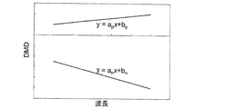
- FIG. 2 is a graph showing mode dispersion characteristics of the optical fibers Fp and Fn according to the present embodiment.
- FIG. 2 shows the mode dispersion characteristics of the optical fibers Fp and Fn in the 1530 to 1625 nm band, which is a predetermined wavelength band for communication.
- the x-axis represents wavelength and the y-axis represents mode dispersion.
- the optical transmission lines F and F ′ (see FIG. 1) using the optical fibers Fp and Fn have the respective lengths of the optical fibers Fp and Fn so as to compensate the mode dispersion without considering the wavelength ⁇ .
- the lengths Lp and Ln the mode dispersion can be sufficiently compensated over the entire 1530 to 1625 nm band.
- the mode dispersion characteristic is the category of “constant mode dispersion”. include. For example, if the slope d ⁇ / d ⁇ of the mode dispersion ⁇ with respect to the wavelength ⁇ is
- the optical fiber according to the present embodiment may be an optical fiber Fp having a positive mode dispersion ⁇ p or an optical fiber Fn having a negative mode dispersion ⁇ n by appropriately changing the refractive index distribution. Is possible.
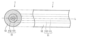
- FIG. 3 is a cross-sectional view and a side view showing the configuration of the optical fiber 1 according to the present embodiment.
- the optical fibers Fp and Fn of the present embodiment (FIGS. 1 and 2) have the same configuration as that of the optical fiber 1.
- the optical fiber 1 is a cylindrical structure whose main component is silica glass.
- the optical fiber 1 includes a core 11 and a clad 12.
- the core 11 has a circular cross section.
- the clad 12 has an annular cross section surrounding the core 11.
- the core 11 includes an inner core 111 and an outer core 112.
- the inner core 111 has a circular cross section.
- the outer core 112 has an annular cross section that surrounds the inner core 111.
- the circle formed by the cross section of the inner core 111 has a radius r1.
- the ring formed by the cross section of the outer core 112 has a radius r1 at its inner periphery and a radius r1 + r2 (radius a) at its outer periphery.
- the cross-sectional structure shown in FIG. 3 is common to each cross section orthogonal to the central axis L.
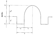
- FIG. 4 is a graph showing the refractive index distribution of the optical fiber 1 according to this embodiment.
- the refractive index distribution shown in FIG. 4 is realized, for example, by a known technique in which the refractive index is locally increased by adding Ge (germanium) or the refractive index is locally decreased by adding F (fluorine). can do.
- the refractive index distribution of the inner core 111 is an ⁇ power type refractive index distribution, and has a maximum value n1 on the central axis L.
- the ⁇ power type refractive index distribution is a refractive index n (r at a point where the distance from the central axis L is r, where ⁇ is a relative refractive index difference between the central portion of the inner core 111 and the outer core 112. )
- n (r) n1 [1-2 ⁇ (r / a) ⁇ ] 1/2 .
- the ⁇ -th power type refractive index distribution gradually approaches a step type refractive index distribution.
- the refractive index n1 'of the outer core 112 and the refractive index n2 of the cladding 12 are constant as shown in FIG.
- the maximum refractive index n1 of the inner core 111, the refractive index n1 'of the outer core 112, and the refractive index n2 of the cladding 12 have a relationship of n1' ⁇ n2 ⁇ n1.
- a recess called “trench” is generated due to the difference (n1 ′ ⁇ n2) between the refractive index n2 of the outer core 112 and the refractive index n1 ′ of the outer core 112. ing.
- ⁇ + represents a relative refractive index difference [(n1 2 ⁇ n2 2 ) / 2n1 2 ] ⁇ 100 [%] between the center portion of the inner core 111 and the clad 12, and ⁇ represents the outer core.
- the relative refractive index difference between 112 and the clad 12 [(n1 ′ 2 ⁇ n2 2 ) / 2n1 ′ 2 ] ⁇ 100 [%].
- the relative refractive index difference ⁇ + is sometimes referred to as “core ⁇ ”.
- Ra and Rd are used in addition to ⁇ and ⁇ + described above as parameters that define the refractive index distribution of the optical fiber 1.
- Ra represents a ratio r1 / a of the radius r1 of the inner core 111 to the radius a of the outer peripheral portion of the outer core 112.
- Rd represents the ratio
- of the absolute value of the relative refractive index difference ⁇ to the absolute value of the relative refractive index difference ⁇ +. That is, the smaller the Rd, the shallower the trench depth (n2-n1 '). When Rd 0, the trench depth becomes zero.
- an equivalent V value T is used as an index representing the propagation characteristics of the optical fiber 1.
- n (r) represents a refractive index at a point where the distance from the central axis L is r, and k represents light incident on the optical fiber 1 (hereinafter referred to as “incident light”).
- incident light hereincident light”.
- Wave number Wave number.
- a in the following mathematical formula (3) is a constant determined by the refractive index distribution.
- the optical fiber 1 having the refractive index distribution shown in FIG. 4, when the equivalent V value T is less than 2.5, the secondary mode (LP11) is blocked, and when the equivalent V value T is 4.5 or less, 3 The next mode (LP21) is shut off. That is, when the equivalent V value T is 2.5 or more and 4.5 or less, the optical fiber 1 functions as a two-mode optical fiber.
- the section on the T-axis where 2.5 ⁇ T ⁇ 4.5 is referred to as “two-mode region”.
- the mode dispersion ⁇ is treated as a function of the equivalent V value T instead of being treated as a function of the wavelength ⁇ .
- the variation of the equivalent V value T is equivalent to the variation of the core radius and the variation of the wavelength ⁇ .
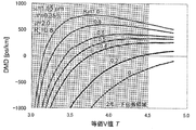
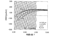
- FIG. 5 is a graph showing the relationship between the parameter Rd and the mode dispersion characteristic for the optical fiber 1 according to the present embodiment.
- FIG. 5 is a graph of ⁇ (T) obtained when Rd is 0, 0.2, 0.4, 0.5, 0.6, 0.8, and 1.0.
- ⁇ is 2.0
- ⁇ + is 0.35%
- Ra is 0.8.
- the wavelength ⁇ of the incident light is 1.55 ⁇ m.
- FIG. 6 is a graph showing the relationship between the parameter Ra and the mode dispersion characteristic for the optical fiber 1 according to the present embodiment.
- FIG. 6 is a graph of ⁇ (T) obtained when Ra is set to 0.4, 0.6, 0.7, 0.75, and 0.8.
- ⁇ is 2.0
- ⁇ + is 0.35%
- Rd is 0.4.
- the wavelength ⁇ of the incident light is 1.55 ⁇ m.
- FIG. 7 is a graph showing the relationship between the parameter ⁇ and the mode dispersion characteristic for the optical fiber 1 according to the present embodiment.
- FIG. 7 is a graph of ⁇ (T) obtained when ⁇ is 1,2,5,10,10000.
- ⁇ + is 0.35%
- Ra is 0.6
- Rd is 0.4.
- the wavelength ⁇ of the incident light is 1.55 ⁇ m.
- FIG. 8 is a graph showing the relationship between the parameter ⁇ + and the mode dispersion characteristic for the optical fiber 1 according to the present embodiment.
- FIG. 8 is a graph of ⁇ (T) obtained when ⁇ + is 0.3%, 0.35%, 0.4%, 0.5%, and 0.6%.
- ⁇ is 2.0
- Ra is 0.6
- Rd is 0.4.
- the wavelength ⁇ of the incident light is 1.55 ⁇ m.
- Rd 0.4 is set under the condition of Ra ⁇ 0.7, an arbitrary value (more surely, 1.0 ⁇ ⁇ ⁇ 10.0) is set to ⁇ ,
- ⁇ + more certainly, 0.3 ⁇ ⁇ + ⁇ 0.6
- a two-mode optical fiber that satisfies the condition of d ⁇ / dT ⁇ 0 can be realized.
- an optical fiber as the optical fibers Fp and Fn, it is possible to realize the optical transmission lines F and F ′ that can sufficiently compensate the mode dispersion over the entire desired wavelength band. it can.
- Example 1 of the optical fiber 1 according to the present embodiment will be described with reference to FIGS. 9A to 9C.
- FIG. 9A shows the set values of parameters that define the refractive index distribution in the optical fiber 1 of the first embodiment.
- FIG. 9B is a graph illustrating mode dispersion characteristics of the optical fiber 1 according to the first embodiment.
- the mode dispersion ⁇ is 290 to 296 ps / km in the 1530 to 1625 nm band, and the slope d ⁇ / of the mode dispersion ⁇ with respect to the wavelength ⁇ .
- d ⁇ was
- FIG. 9C is a graph showing the relationship between the fluctuation amount of the core radius and the mode dispersion characteristic for the optical fiber 1 according to the first embodiment.
- the slope of the mode dispersion ⁇ with respect to the core radius is
- the optical fiber 1 according to the present embodiment has a mode based on fluctuations in the wavelength ⁇ and the core diameter by appropriately setting each parameter as shown in FIG. It was confirmed that the influence of dispersion was small. Therefore, by using the optical fiber in which each parameter is set as described above as the optical fiber Fp, the optical transmission lines F and F ′ capable of sufficiently compensating the mode dispersion over the entire desired wavelength band are provided. Can be realized.
- Example 2 of the optical fiber 1 according to this embodiment will be described with reference to FIGS. 10 (a) to 10 (c).
- FIG. 10A shows the set values of parameters that define the refractive index distribution in the optical fiber 1 of the second embodiment.
- FIG. 10B is a graph illustrating mode dispersion characteristics of the optical fiber 1 according to the second embodiment.
- the mode dispersion ⁇ is ⁇ 540 to ⁇ 530 ps / km in the 1530 to 1625 nm band, and the slope of the mode dispersion ⁇ with respect to the wavelength ⁇ .
- d ⁇ / d ⁇ was
- FIG. 10C is a graph showing the relationship between the fluctuation amount of the core radius and the mode dispersion characteristic for the optical fiber 1 according to the second embodiment.
- the slope of the mode dispersion ⁇ with respect to the core radius is
- the optical fiber 1 according to the present embodiment has a mode based on fluctuations in the wavelength ⁇ and the core diameter by appropriately setting each parameter as shown in FIG. It was confirmed that the influence of dispersion was small. Therefore, by using the optical fiber in which each parameter is set as described above as the optical fiber Fn, the optical transmission lines F and F ′ capable of sufficiently compensating the mode dispersion over the entire desired wavelength band are provided. Can be realized.
- Example 3 of the optical fiber 1 according to this embodiment will be described with reference to FIGS. 11 (a) to 11 (c).
- FIG. 11A shows the set values of the parameters that define the refractive index distribution in the optical fiber 1 of the third embodiment.
- FIG. 11B is a graph illustrating mode dispersion characteristics of the optical fiber 1 according to the third embodiment.
- FIG. 11B in the optical fiber 1 of Example 3, in the 1530 to 1625 nm band, the mode dispersion ⁇ is 315 to 325 ps / km, and the slope of the mode dispersion ⁇ with respect to the wavelength ⁇ d ⁇ / d ⁇ was
- FIG. 11C is a graph showing the relationship between the fluctuation amount of the core radius and the mode dispersion characteristic for the optical fiber 1 according to the third embodiment.
- the slope of the mode dispersion ⁇ with respect to the core radius is
- the optical fiber 1 according to the present embodiment can be set in a mode based on fluctuations in the wavelength ⁇ and the core diameter by appropriately setting each parameter as shown in FIG. It was confirmed that the influence of dispersion was small. Therefore, by using the optical fiber in which each parameter is set as described above as the optical fiber Fp, the optical transmission lines F and F ′ capable of sufficiently compensating the mode dispersion over the entire desired wavelength band are provided. Can be realized.
- Example 4 of the optical fiber 1 according to this embodiment will be described with reference to FIGS. 12 (a) to 12 (c).
- FIG. 12A shows the set values of the parameters that define the refractive index distribution in the optical fiber 1 of the fourth embodiment.
- FIG. 12B is a graph illustrating mode dispersion characteristics of the optical fiber 1 according to the fourth embodiment.
- FIG. 12B in the optical fiber 1 of Example 4, in the 1530 to 1625 nm band, the mode dispersion ⁇ becomes 2820 to 2835 ps / km, and the slope d ⁇ / of the mode dispersion ⁇ with respect to the wavelength ⁇ . d ⁇ was
- FIG. 12C is a graph showing the relationship between the fluctuation amount of the core radius and the mode dispersion characteristic for the optical fiber 1 according to the fourth embodiment.
- the slope of the mode dispersion ⁇ with respect to the core radius is
- the optical fiber 1 according to the present embodiment has a mode based on fluctuations in the wavelength ⁇ and the core diameter by appropriately setting each parameter as shown in FIG. It was confirmed that the influence of dispersion was small. Therefore, by using the optical fiber in which each parameter is set as described above as the optical fiber Fp, the optical transmission lines F and F ′ capable of sufficiently compensating the mode dispersion over the entire desired wavelength band are provided. Can be realized.
- Example 5 of the optical fiber 1 according to the present embodiment will be described with reference to FIGS. 13 (a) to 13 (c).
- FIG. 13A shows the set values of the parameters that define the refractive index distribution in the optical fiber 1 of the fifth embodiment.
- FIG. 13B is a graph illustrating mode dispersion characteristics of the optical fiber 1 according to the fifth embodiment.
- FIG. 13C is a graph showing the relationship between the fluctuation amount of the core radius and the mode dispersion characteristic for the optical fiber 1 according to the fifth embodiment.
- the slope of the mode dispersion ⁇ with respect to the core radius is
- the optical fiber 1 according to the present embodiment can be set in a mode based on fluctuations in the wavelength ⁇ and the core diameter by appropriately setting each parameter as shown in FIG. It was confirmed that the influence of dispersion was small. Therefore, by using the optical fiber in which each parameter is set as described above as the optical fiber Fp, the optical transmission lines F and F ′ capable of sufficiently compensating the mode dispersion over the entire desired wavelength band are provided. Can be realized.
- Example 6 An example (Example 6) of the optical transmission line F according to the present embodiment will be described with reference to FIGS. 14 (a) and 14 (b).
- FIG. 14A shows the mode dispersion ⁇ of the optical fibers Fp and Fn in the optical transmission line F of the sixth embodiment.
- FIG. 14B is a graph showing mode dispersion characteristics of the optical transmission line F in the sixth embodiment.
- Example 6 the optical fiber 1 of Example 1 was used as the optical fiber Fp, and the optical fiber 1 of Example 2 was used as the optical fiber Fn to configure the optical transmission line F. That is, in the sixth embodiment, the optical transmission line F is configured by using the optical fibers Fp and Fp whose mode dispersion ⁇ is substantially constant in the 1530 to 1625 nm band.
- the mode dispersion ⁇ of each optical fiber is as shown in FIG.
- the mode dispersion characteristic of F was determined.
- the mode dispersion ⁇ is ⁇ 2 to 2 ps / km, the mode dispersion ⁇ is extremely small, and the mode dispersion is It was confirmed that the influence of ⁇ on wavelength ⁇ was extremely small. Therefore, it was confirmed that the optical fiber 1 of Example 5 can sufficiently compensate the mode dispersion over the entire 1530 to 1625 nm band.
- FIG. 15 shows the set values of parameters that define the refractive index distribution in the optical fiber of this comparative example.
- FIG. 16 is a graph showing mode dispersion characteristics of the optical fiber according to this comparative example.
- the mode dispersion ⁇ is ⁇ 600 to ⁇ 460 ps / km in the 1530 to 1625 nm band, and the slope d ⁇ of the mode dispersion ⁇ with respect to the wavelength ⁇ . / D ⁇ was
- the mode dispersion ⁇ in the optical fiber with a trench, in the 1530 to 1625 nm band, the mode dispersion ⁇ is 305 to 385 ps / km, and the slope d ⁇ / d ⁇ of the mode dispersion ⁇ with respect to the wavelength ⁇ is
- FIG. 17 is a graph showing the relationship between the fluctuation amount of the core radius and the mode dispersion characteristic for the optical fiber according to this comparative example.
- the slope of the mode dispersion ⁇ with respect to the core radius is
- the optical fiber with a trench has an inclination of mode dispersion ⁇ with respect to the core radius of
- the wavelength band to be compensated for mode dispersion is the 1530 to 1625 nm band, but is not limited thereto. It will be apparent from the content of this document to those skilled in the art that the present invention can make other wavelength bands subject to modal dispersion compensation.
- the optical fiber according to one embodiment of the present invention is a two-mode optical fiber that propagates the LP01 mode component and the LP11 mode component included in the signal light, and the above formula ( The mode dispersion ⁇ defined by 2) is constant.
- vg11 represents the group velocity of the LP11 mode component
- vg01 represents the group velocity of the LP01 mode component.
- the slope d ⁇ / d ⁇ of the mode dispersion ⁇ with respect to the wavelength ⁇ is
- the slope d ⁇ / d ⁇ of the mode dispersion ⁇ with respect to the wavelength ⁇ is preferably
- each of the above optical fibers there is almost no variation in the mode dispersion characteristic due to the wavelength ⁇ , so the first optical fiber having a mode dispersion characteristic with a positive sign and the first optical fiber having a mode dispersion characteristic with a negative sign.
- Each of the two optical fibers is configured like the optical fiber, and further, by combining the first optical fiber and the second optical fiber with an appropriate length, over a wide wavelength band.
- An optical transmission line in which mode dispersion compensation is performed can be realized.
- the above-described optical fiber provides mode dispersion compensation over the entire communication wavelength band of 1530 to 1625 nm (but not limited to this). It can be seen that the optical transmission line made can be realized, and thus the optical fiber is more useful.
- the refractive index distribution is ⁇ power type
- the maximum refractive index is n1
- the inner core surrounds the inner core
- the refractive index n1 ′ surrounds the outer core.
- a clad having a refractive index of n2 (n1 ′ ⁇ n2 ⁇ n1).
- the radius of the inner core is r1
- the radius of the outer periphery of the outer core is a
- the relative refractive index difference between the outer core and the cladding is ⁇
- An optical transmission line uses the optical fiber, uses the first optical fiber in which the sign of the mode dispersion ⁇ is positive, and the optical fiber, and And a second optical fiber having a negative sign of the mode dispersion ⁇ .
- optical transmission line it is possible to realize an optical transmission line capable of sufficiently compensating mode dispersion over the entire desired wavelength band.
- the present invention can be used for an optical transmission line for communication, and can be particularly suitably used for an optical transmission line for communication by wavelength division division division or mode division division.
Landscapes
- Physics & Mathematics (AREA)
- General Physics & Mathematics (AREA)
- Optics & Photonics (AREA)
- Chemical & Material Sciences (AREA)
- Dispersion Chemistry (AREA)
- Optical Communication System (AREA)
- Optical Fibers, Optical Fiber Cores, And Optical Fiber Bundles (AREA)
Abstract
光伝送路Fが備える光ファイバFp、Fnは、信号光に含まれるLP01及びLP11のモード成分を伝搬する2モード光ファイバであり、1530~1625nmの波長帯域において、波長λに対するモード分散Δτの傾きdΔτ/dλが、|0.5|ps/km/nm以下である。前記光ファイバFp、Fnは、前記モード分散Δτの符号が、互いに、反対である。前記光伝送路によれば、広い波長帯域にわたって、モード分散を十分に補償することができる。
Description
本発明は、光ファイバおよび光伝送路に関する。
光情報通信においては、通信量の増加に伴い、伝送媒体となる光ファイバに求められる伝送容量も増加してきている。特に、WDM(波長多重分割)方式による長距離伝送用の光ファイバにおいて、このような要求は顕著である。通信量は今後も増加の一途を辿ることが予想されており、伝送容量の増加は光ファイバにおける喫緊の課題となっている。
そこで、近年、伝送容量の増加に対応すべく、複数のモードを伝搬させることが可能なFMF(Few-Mode Fiber)を伝送路に用い、各モードに対して対応する信号を重畳することにより複数の信号を多重化送信する、MDM(モード分割多重)伝送が注目を集めている。
しかしながら、FMFにおいては、モード分散の発生が避けられない。モード分散は、伝送距離に比例した伝送容量の低下を生じさせる。したがって、長距離伝送に耐える大容量のマルチモードファイバを実現するためには、モード分散を抑えることが重要になる。
例えば、MDM伝送において採用され得るMIMO(Multiple-Input-Multiple-Output)の処理演算量は、FMFのモード分散が大きいほど増加することが知られている。このため、FMFのモード分散が大きいと、MIMOの処理に遅延が生じる虞がある。このため、MDM伝送では、モード分散が小さいFMFが必要となってくる。さらに、MDM伝送は、WDM伝送との併用が想定されるため、広い波長帯域に亘ってモード分散を小さくする必要がある。
そこで、モード分散特性が異なる複数の光ファイバを組み合わせることにより、光伝送路におけるモード分散を補償する技術が考案されている。例えば、下記特許文献1には、2つのMMF(Multimode Fiber)を好適に組み合わせることにより、最適化された波長(例えば、0.85μm)以外の他の波長(例えば、1.3μm)においても、モード分散を補償することにより、伝送帯域幅を拡大する技術が開示されている。
また、下記非特許文献1,2には、モード分散の符号と、モード分散の波長に対する傾きの符号との各々が互いに異なる、2以上の2モードファイバを接続することにより、より広い波長帯域に亘ってモード分散を小さくする技術が開示されている。
特に、下記非特許文献1では、グレーデッドインデックスコアにトレンチ構造を付与した構造の2モードファイバと、グレーデッドインデックスコアのみを有する構造の2モードファイバとを接続した光伝送路が提案されており、当該光伝送路を用いて、光通信用の波長帯域であるC+L-bandにおいて数ps/km以下のモード分散を達成できることが示されている。
また、下記非特許文献2では、階段状の屈折率分布を有する2モード光ファイバが提案されており、各パラメータが調整された4本の光ファイバが接続された光伝送路を用いて、C+L-bandにおいて数ps/km以下のモード分散を達成できるとされている。
Ryo Maruyama, et al, "DMD Free Transmission Line Composed of TMFs with Large Effective Area for MIMO Processing", ECOC2012, Tu.1.F.2 (2012/6/16)
Taiji Sakamoto, et al, "Differential Mode Delay Managed Transmission Line for Wide-band WDM-MIMO System",OFC 2012, OM2D.1 (2012/3/4)
しかしながら、上記非特許文献1,2の技術を用いたとしても、広い波長帯域に亘ってモード分散を十分に補償することは容易ではない。これは、従来の2モード光ファイバは、そのモード分散Δτが波長λに対して傾きを有している、すなわち、モード分散Δτが波長λに依存するという特性を有しているためである。この点に関し、図18を参照してより具体的に説明する。図18は、従来の光ファイバのモード分散特性を示すグラフである(x軸は波長、y軸はモード分散を示す)。この図18に示すように、正のモード分散Δτpは、1次関数y=apx+bp(ap>0)によって近似可能な特性を有しており、負のモード分散Δτnは、1次関数y=anx+bn(an<0)によって近似可能な特性を有している。
このため、従来の光伝送路(例えば、非特許文献1,2に開示されている光伝送路)においては、ある波長λを基準として、モード分散を補償するように2つの2モード光ファイバ(正のモード分散Δτpをもつ2モード光ファイバ、および、負のモード分散Δτnをもつ2モード光ファイバ)を組み合わせたとしても、他の波長λの信号光に対してモード分散を十分に補償することは容易ではない。よって、従来の光伝送路においては、広い波長帯域に亘ってモード分散を十分に補償することができなかった。
上記の課題に関する発明者の知見によれば、従来の光伝送路であっても、下記数式(1)を満たすことにより、広い波長帯域に亘ってモード分散Δτを補償することが可能である。しかしながら、上記モード分散Δτは、その波長λに対する傾きがコア半径の変動に対して鈍感であるのに対し、その値がコア半径の変動に対して敏感であるため、コア半径が変動してしまうと、下記数式(1)の関係が大きく崩れてしまう。このため、広い波長帯域に亘ってモード分散を十分に補償することのできる光伝送路を実現するという課題は、依然として未解決のままであった。
本発明は、上記の課題に鑑みて、発明者の更なる知見に基づきなされたものであり、その目的は、広い波長帯域に亘ってモード分散を十分に補償することが可能な光ファイバおよび光伝送路を実現することにある。
上記課題を解決するために、本発明の一態様に係る光ファイバは、信号光に含まれるLP01モード成分およびLP11モード成分を伝搬する2モード光ファイバであって、予め定められた波長帯域において、下記数式(2)により定義されるモード分散Δτが一定であることを特徴とする。下記数式(2)において、vg11は、前記LP11モード成分の群速度を示し、vg01は、前記LP01モード成分の群速度を示す。

本発明によれば、広い波長帯域に亘ってモード分散を十分に補償することが可能な光ファイバおよび光伝送路を実現することができる。
以下、図1~図8を参照して、本発明の一実施形態に係る光伝送路および光ファイバについて説明する。なお、本書および添付の図面においては、モード分散Δτを、DMD(Differential Modal Group Delay)と示す場合もある。
〔光伝送路の構成〕
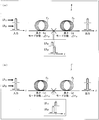
図1は、本実施形態に係る光伝送路F,F’の構成を示す。光伝送路F,F’は、いずれも、図1に示すように、少なくとも2本の光ファイバFp,Fnを含んで構成されている。光ファイバFpは、正のモード分散Δτpを有する2モード光ファイバであり、光ファイバFnは、負のモード分散Δτnを有する2モード光ファイバである。モード分散Δτp,Δτnは、いずれも、上記数式(2)によって定義されるものである。
図1は、本実施形態に係る光伝送路F,F’の構成を示す。光伝送路F,F’は、いずれも、図1に示すように、少なくとも2本の光ファイバFp,Fnを含んで構成されている。光ファイバFpは、正のモード分散Δτpを有する2モード光ファイバであり、光ファイバFnは、負のモード分散Δτnを有する2モード光ファイバである。モード分散Δτp,Δτnは、いずれも、上記数式(2)によって定義されるものである。
図1(a)は、正のモード分散Δτpを有する光ファイバFpを入力側に配置し、負のモード分散Δτnを有する光ファイバFnを出力側に配置した、光伝送路Fの構成例を示している。この光伝送路Fにおいて、LP11モード成分が光ファイバFpを伝搬するために要する時間は、LP01モード成分が光ファイバFpを伝搬するために要する時間よりもΔτp×Lp(Lp=光ファイバFpの長さ)だけ長い。したがって、LP11モード成分は、光ファイバFpを伝搬する過程で、Δτp×Lpだけ遅れることとなる。
一方、この光伝送路Fにおいて、LP11モード成分が光ファイバFnを伝搬ために要する時間は、LP01モード成分が光ファイバFnを伝搬するために要する時間よりもΔτn×Ln(Ln=光ファイバFnの長さ)だけ短い。したがって、LP11モード成分は、光ファイバFnを伝搬する過程で、Δτn×Lnだけ遅れを取り戻すこととなる。
したがって、光伝送路Fにおいて、Δτp×Lp+Δτn×Lnが十分小さくなるように、より好ましくは、Δτp×Lp+Δτn×Ln=0となるように、光ファイバFpの長さLp及び光ファイバFnの長さLnを設定することにより、当該光伝送路Fにおけるモード分散を十分に補償し、モード分散が殆ど生じない光伝送路Fを実現することができる。
特に、本実施形態の光伝送路Fにおいては、光ファイバFp,Fnとして、モード分散特性が波長λに依存しないもの(図2参照)を用いているため、波長λを考慮することなく、モード分散を補償するように光ファイバFp,Fnの各々の長さを設定することにより、結果的に、所望の波長帯域の全域に亘って、モード分散を十分に補償することができる。
図1(b)は、負のモード分散Δτnを有する光ファイバFnを入力側に配置し、正のモード分散Δτpを有する光ファイバFpを出力側に配置した、光伝送路F’の構成例を示している。この光伝送路F’において、LP01モード成分が光ファイバFnを伝搬するのに要する時間は、LP11モード成分が光ファイバFnを伝搬するのに要する時間よりもΔτp×Lpだけ長い。したがって、LP01モード成分は、光ファイバFnを伝搬する過程で、Δτn×Lnだけ遅れることとなる。
一方、この光伝送路F’において、LP01モード成分が光ファイバFpを伝搬するのに要する時間は、LP11モード成分が光ファイバFpを伝搬するのに要する時間よりもΔτp×Lpだけ短い。したがって、LP01モード成分は、光ファイバFpを伝搬する過程で、Δτp×Lpだけ遅れを取り戻すこととなる。
したがって、光伝送路F’において、Δτp×Lp+Δτn×Lnが十分小さくなるように、より好ましくは、Δτp×Lp+Δτn×Ln=0となるように、光ファイバFpの長さLp及び光ファイバFnの長さLnを設定することにより、当該光伝送路F’におけるモード分散を十分に補償し、モード分散が殆ど生じない光伝送路F’を実現することができる。
特に、本実施形態の光伝送路F’においては、光ファイバFp,Fnとして、モード分散特性が波長λに依存しないもの(図2参照)を用いているため、波長λを考慮することなく、モード分散を補償するように光ファイバFp,Fnの各々の長さを設定することにより、結果的に、所望の波長帯域の全域に亘って、モード分散を十分に補償することができる。
〔光ファイバのモード分散特性〕
図2は、本実施形態に係る光ファイバFp,Fnのモード分散特性を示すグラフである。特に、図2は、予め定められた通信用の波長帯域である、1530~1625nm帯における、光ファイバFp,Fnのモード分散の特性を示している。図2において、x軸は波長、y軸はモード分散を示す。
図2は、本実施形態に係る光ファイバFp,Fnのモード分散特性を示すグラフである。特に、図2は、予め定められた通信用の波長帯域である、1530~1625nm帯における、光ファイバFp,Fnのモード分散の特性を示している。図2において、x軸は波長、y軸はモード分散を示す。
図2において注目すべき点は、光ファイバFpは、y=bpによって表される正のモード分散特性を有しており、光ファイバFnは、y=bnによって表される負のモード分散特性を有していることである。すなわち、光ファイバFpのモード分散Δτpの波長λに対する傾きdΔτp/dλはゼロであり、光ファイバFnのモード分散Δτnの波長λに対する傾きdΔτn/dλもゼロである。要するに、少なくとも1530~1625nm帯において、光ファイバFpのモード分散Δτpおよび光ファイバFnのモード分散Δτnは、いずれも波長λに依存することなく、一定となっている。
これにより、光ファイバFp,Fnを用いた光伝送路F,F’(図1参照)は、特に波長λを考慮することなく、モード分散を補償するように光ファイバFp,Fnの各々の長さLp,Lnを設定することにより、結果的に、1530~1625nm帯全域に亘って、モード分散を十分に補償することができる。
なお、本書における「モード分散が一定」とは、モード分散の波長λに対する傾き=0に限らず、モード分散の波長λに対する傾き≒0であってもよい。要するに、1530~1625nm帯全域に亘ってモード分散を十分に補償することができる程度に、モード分散の波長λに対する傾きが十分に小さければ、そのモード分散特性は、「モード分散が一定」の範疇に含まれる。例えば、波長λに対するモード分散Δτの傾きdΔτ/dλが、|0.5ps|/km/nm以下であれば、「モード分散が一定」の範疇に含まれる。
なお、本実施形態に係る光ファイバは、屈折率分布を適宜変更することによって、正のモード分散Δτpを有する光ファイバFpとすることも、負のモード分散Δτnを有する光ファイバFnとすることも可能である。
〔光ファイバの構成〕
図3は、本実施形態に係る光ファイバ1の構成を示す断面図および側面図である。本実施形態(図1,2)の光ファイバFp,Fnは、この光ファイバ1と同様の構成を有している。
図3は、本実施形態に係る光ファイバ1の構成を示す断面図および側面図である。本実施形態(図1,2)の光ファイバFp,Fnは、この光ファイバ1と同様の構成を有している。
光ファイバ1は、シリカガラスを主成分とする円柱状の構造体である。光ファイバ1は、コア11と、クラッド12とを備えて構成されている。コア11は、円形状の断面を有する。クラッド12は、コア11を取り囲む円環状の断面を有する。
コア11は、内側コア111と、外側コア112とを備えて構成されている。内側コア111は、円形状の断面を有する。外側コア112は、内側コア111を取り囲む円環状の断面を有する。内側コア111の断面がなす円は、半径r1を有している。外側コア112の断面がなす円環は、その内周部が半径r1を有しており、その外周部が半径r1+r2(半径a)を有している。光ファイバ1において、図3に示す断面構造は、中心軸Lに直交する各断面において共通である。
(光ファイバの屈折率分布)
図4は、本実施形態に係る光ファイバ1の屈折率分布を示すグラフである。なお、図4に示す屈折率分布は、例えば、Ge(ゲルマニウム)の添加によって屈折率を局所的に上げたり、F(フッ素)の添加によって屈折率を局所的に下げたりする公知の手法により実現することができる。
図4は、本実施形態に係る光ファイバ1の屈折率分布を示すグラフである。なお、図4に示す屈折率分布は、例えば、Ge(ゲルマニウム)の添加によって屈折率を局所的に上げたり、F(フッ素)の添加によって屈折率を局所的に下げたりする公知の手法により実現することができる。
内側コア111の屈折率分布は、図4に示すように、α乗型の屈折率分布であり、中心軸L上で最大値n1をとる。ここで、α乗型の屈折率分布とは、内側コア111の中心部と外側コア112との比屈折率差をδとして、中心軸Lからの距離がrである点の屈折率n(r)がn(r)=n1[1-2δ(r/a)α]1/2と表される屈折率分布のことを指す。なお、αを大きくしていくと、α乗型の屈折率分布は、ステップ型の屈折率分布に漸近する。
外側コア112の屈折率n1’、および、クラッド12の屈折率n2は、図4に示すように一定である。内側コア111の最大屈折率n1、外側コア112の屈折率n1’、およびクラッド12の屈折率n2は、n1’<n2<n1という関係を有している。図4に示す光ファイバ1の屈折率分布には、外側コア112の屈折率n2と、外側コア112の屈折率n1’との差(n1’<n2)により、「トレンチ」と呼ばれる凹部が生じている。
なお、図4において、Δ+は、内側コア111の中心部とクラッド12との比屈折率差[(n12-n22)/2n12] ×100[%]を表し、Δ-は、外側コア112とクラッド12との比屈折率差[(n1’2-n22)/2n1’2]×100[%]を表す。比屈折率差Δ+は、「コアΔ」と呼ばれることもある。
以下の説明においては、光ファイバ1の屈折率分布を規定するパラメータとして、上述したαおよびΔ+の他に、RaおよびRdを用いる。Raは、外側コア112の外周部の半径aに対する内側コア111の半径r1の比r1/aを表す。また、Rdは、比屈折率差Δ+の絶対値に対する比屈折率差Δ-の絶対値の比|Δ-|/|Δ+|を表す。すなわち、Rdが小さくなるほど、トレンチの深さ(n2-n1’)は浅くなり、Rd=0のとき、トレンチの深さは0になる。
また、以下の説明においては、光ファイバ1の伝搬特性を表す指標として、等価V値Tを用いる。等価V値Tは、T=∫[n2(r)-n2(∞)k]1/2dr(積分範囲は0から∞)により定義され、規格化周波数Vとの間に下記数式(3)の関係を有する。等価V値Tの定義式において、n(r)は、中心軸Lからの距離がrである点における屈折率を表し、kは、光ファイバ1に入射させる光(以下「入射光」と記載)の波数を表す。下記数式(3)におけるAは、屈折率分布によって決定される定数である。

図4に示す屈折率分布を有する光ファイバ1においては、等価V値Tが2.5未満の場合、2次モード(LP11)が遮断され、等価V値Tが4.5以下の場合、3次モード(LP21)が遮断される。すなわち、この等価V値Tが2.5以上4.5以下であるときに、光ファイバ1は2モード光ファイバとして機能する。以下、2.5≦T≦4.5であるT軸上の区間のことを、「2モード領域」と記載する。
(屈折率分布とモード分散特性との関係)
次に、光ファイバ1の屈折率分布とモード分散特性との関係について、図5~図8を参照して説明する。なお、以下の説明においては、モード分散Δτを波長λの関数として扱う代わりに等価V値Tの関数として扱う。上記数式(3)から明らかなように、等価V値Tの変動は、コア半径の変動および波長λの変動と等価である。したがって、等価V値Tに対するモード分散Δτの傾き(dΔτ/dT)が≒0であれば、コア半径に対するモード分散Δτの傾き、および波長λに対するモード分散Δτの傾きは、いずれも≒0となる。
次に、光ファイバ1の屈折率分布とモード分散特性との関係について、図5~図8を参照して説明する。なお、以下の説明においては、モード分散Δτを波長λの関数として扱う代わりに等価V値Tの関数として扱う。上記数式(3)から明らかなように、等価V値Tの変動は、コア半径の変動および波長λの変動と等価である。したがって、等価V値Tに対するモード分散Δτの傾き(dΔτ/dT)が≒0であれば、コア半径に対するモード分散Δτの傾き、および波長λに対するモード分散Δτの傾きは、いずれも≒0となる。
まず、パラメータRdがモード分散特性に及ぼす影響について、図5を参照して説明する。図5は、本実施形態に係る光ファイバ1に関して、パラメータRdとモード分散特性との関係を示すグラフである。特に、図5は、Rdを0,0.2,0.4,0.5,0.6,0.8,1.0としたときに得られるΔτ(T)のグラフである。ここでは、αを2.0とし、Δ+を0.35%とし、Raを0.8としている。また、入射光の波長λは、1.55μmとしている。
図5に示すグラフから、パラメータRdを変化させることで、等価V値Tに対するモード分散Δτの傾き(dΔτ/dT)が変化することがわかる。特に、Rdを徐々に増加させていくと、Rd=0.4付近において、dΔτ/dT≒0となることがわかる。したがって、Rd=0.4付近に設定することでdΔτ/dTを≒0に制御できることがわかる。
次に、パラメータRaがモード分散特性に及ぼす影響について、図6を参照して説明する。図6は、本実施形態に係る光ファイバ1に関して、パラメータRaとモード分散特性との関係を示すグラフである。特に、図6は、Raを0.4,0.6,0.7,0.75,0.8としたときに得られるΔτ(T)のグラフである。ここでは、αを2.0とし、Δ+を0.35%とし、Rdを0.4としている。また、入射光の波長λは、1.55μmとしている。
図6に示すグラフから、Raを変化させることにより、モード分散特性が横軸方向にシフト(すなわち、等価V値Tが変化)することがわかる。特に、等価V値Tが大きくなるにつれ、dΔτ/dTは0に近づいていくことがわかる。そして、2モード領域にdΔτ/dT≒0の解が得られるRaの条件はRa≦0.7のときであることがわかる。したがって、Ra≦0.7に設定することでdΔτ/dTを≒0に制御できることがわかる。
次に、パラメータαがモード分散特性に及ぼす影響について、図7を参照して説明する。図7は、本実施形態に係る光ファイバ1に関して、パラメータαとモード分散特性との関係を示すグラフである。特に、図7は、αを1,2,5,10,10000としたときに得られるΔτ(T)のグラフである。ここでは、Δ+を0.35%とし、Raを0.6とし、Rdを0.4としている。また、入射光の波長λは、1.55μmとしている。
図7に示すグラフから、αを変化させることにより、モード分散特性が縦軸方向にシフト(すなわち、モード分散Δτが変化)することがわかる。一方、図7に示すグラフから、αを1.0~10.0の範囲内で変化させた場合であっても、dΔτ/dT≒0のまま、dΔτ/dTが殆ど変化しないことがわかる。したがって、αに任意の値(より確実には、1.0≦α≦10.0)を設定することでdΔτ/dTを≒0に制御できることがわかる。
次に、パラメータΔ+がモード分散特性に及ぼす影響について、図8を参照して説明する。図8は、本実施形態に係る光ファイバ1に関して、パラメータΔ+とモード分散特性との関係を示すグラフである。特に、図8は、Δ+を0.3%,0.35%,0.4%,0.5%,0.6%としたときに得られるΔτ(T)のグラフである。ここでは、αを2.0とし、Raを0.6とし、Rdを0.4としている。また、入射光の波長λは、1.55μmとしている。
図8に示すグラフから、Δ+を変化させることにより、モード分散特性が縦軸方向にシフト(すなわち、モード分散Δτが変化)することがわかる。一方、図8に示すグラフから、Δ+を0.3~0.6の範囲内で変化させた場合であっても、dΔτ/dTが殆ど変化しないことがわかる。したがって、Δ+に任意の値(より確実には、0.3≦Δ+≦0.6)を設定することでdΔτ/dTを≒0に制御できることがわかる。
以上のように、Ra≦0.7という条件の下、Rd=0.4付近に設定し、αに任意の値(より確実には、1.0≦α≦10.0)を設定し、Δ+に任意の値(より確実には、0.3≦Δ+≦0.6)を設定することで、dΔτ/dT≒0という条件を満たす2モード光ファイバを実現することができる。そして、このような光ファイバを光ファイバFp,Fnとして用いることにより、所望の波長帯域の全域に亘って、モード分散を十分に補償することができる光伝送路F,F’を実現することができる。
〔実施例1〕
本実施形態に係る光ファイバ1の実施例1について、図9(a)~図9(c)を参照して説明する。図9(a)は、実施例1の光ファイバ1における、屈折率分布を規定する各パラメータの設定値を示す。図9(b)は、実施例1に係る光ファイバ1の、モード分散特性を示すグラフである。
本実施形態に係る光ファイバ1の実施例1について、図9(a)~図9(c)を参照して説明する。図9(a)は、実施例1の光ファイバ1における、屈折率分布を規定する各パラメータの設定値を示す。図9(b)は、実施例1に係る光ファイバ1の、モード分散特性を示すグラフである。
図9(a)に示すように、本実施例1では、Ra=0.7、Rd=0.4、α=2.0、Δ+=0.35を設定した。この結果、図9(b)に示すように、実施例1の光ファイバ1は、1530~1625nm帯において、モード分散Δτは、290~296ps/kmとなり、モード分散Δτの波長λに対する傾きdΔτ/dλは、|0.15|ps/km/nm以下となり、上記傾きが極めて小さいものとなった。したがって、実施例1の光ファイバ1は、1530~1625nm帯全域に亘って、モード分散を十分に補償することができるものであることが確認された。
ここで、実施例1の光ファイバ1において、コア半径の変動がモード分散特性に及ぼす影響について、図9(c)を参照して説明する。図9(c)は、実施例1に係る光ファイバ1に関して、コア半径の変動量とモード分散特性との関係を示すグラフである。図9(c)に示すように、実施例1の光ファイバ1は、コア半径に対するモード分散Δτの傾きが、|25|ps/km/μm以下であり、コア径の変動によるモード分散の影響が非常に小さいものであることが確認された。
以上のように、本実施例1によれば、本実施形態の光ファイバ1は、図9(a)に示すように各パラメータを適切に設定することにより、波長λおよびコア径の変動によるモード分散の影響が小さいものとなることが確認された。したがって、このように各パラメータが設定された光ファイバを光ファイバFpとして用いることにより、所望の波長帯域の全域に亘って、モード分散を十分に補償することができる光伝送路F,F’を実現することができる。
〔実施例2〕
本実施形態に係る光ファイバ1の実施例2について、図10(a)~図10(c)を参照して説明する。図10(a)は、実施例2の光ファイバ1における、屈折率分布を規定する各パラメータの設定値を示す。図10(b)は、実施例2に係る光ファイバ1の、モード分散特性を示すグラフである。
本実施形態に係る光ファイバ1の実施例2について、図10(a)~図10(c)を参照して説明する。図10(a)は、実施例2の光ファイバ1における、屈折率分布を規定する各パラメータの設定値を示す。図10(b)は、実施例2に係る光ファイバ1の、モード分散特性を示すグラフである。
図10(a)に示すように、本実施例2では、Ra=0.6、Rd=0.4、α=1.4、Δ+=0.35を設定した。この結果、図10(b)に示すように、実施例2の光ファイバ1は、1530~1625nm帯において、モード分散Δτは、-540~-530ps/kmとなり、モード分散Δτの波長λに対する傾きdΔτ/dλは、|0.10|ps/km/nm以下となり、上記傾きが極めて小さいものとなった。したがって、実施例2の光ファイバ1は、1530~1625nm帯全域に亘って、モード分散を十分に補償することができるものであることが確認された。
ここで、実施例2の光ファイバ1において、コア半径の変動がモード分散特性に及ぼす影響について、図10(c)を参照して説明する。図10(c)は、実施例2に係る光ファイバ1に関して、コア半径の変動量とモード分散特性との関係を示すグラフである。図10(c)に示すように、実施例2の光ファイバ1は、コア半径に対するモード分散Δτの傾きが、|6|ps/km/μm以下であり、コア径の変動によるモード分散の影響が非常に小さいものであることが確認された。
以上のように、本実施例2によれば、本実施形態の光ファイバ1は、図10(a)に示すように各パラメータを適切に設定することにより、波長λおよびコア径の変動によるモード分散の影響が小さいものとなることが確認された。したがって、このように各パラメータが設定された光ファイバを光ファイバFnとして用いることにより、所望の波長帯域の全域に亘って、モード分散を十分に補償することができる光伝送路F,F’を実現することができる。
〔実施例3〕
本実施形態に係る光ファイバ1の実施例3について、図11(a)~図11(c)を参照して説明する。図11(a)は、実施例3の光ファイバ1における、屈折率分布を規定する各パラメータの設定値を示す。図11(b)は、実施例3に係る光ファイバ1の、モード分散特性を示すグラフである。
本実施形態に係る光ファイバ1の実施例3について、図11(a)~図11(c)を参照して説明する。図11(a)は、実施例3の光ファイバ1における、屈折率分布を規定する各パラメータの設定値を示す。図11(b)は、実施例3に係る光ファイバ1の、モード分散特性を示すグラフである。
図11(a)に示すように、本実施例3では、Ra=0.3、Rd=0.4、α=2.0、Δ+=0.35を設定した。この結果、図11(b)に示すように、実施例3の光ファイバ1は、1530~1625nm帯において、モード分散Δτは、315~325ps/kmとなり、モード分散Δτの波長λに対する傾きdΔτ/dλは、|0.20|ps/km/nm以下となり、上記傾きが極めて小さいものとなった。したがって、実施例3の光ファイバ1は、1530~1625nm帯全域に亘って、モード分散を十分に補償することができるものであることが確認された。
ここで、実施例3の光ファイバ1において、コア半径の変動がモード分散特性に及ぼす影響について、図11(c)を参照して説明する。図11(c)は、実施例3に係る光ファイバ1に関して、コア半径の変動量とモード分散特性との関係を示すグラフである。図11(c)に示すように、実施例3の光ファイバ1は、コア半径に対するモード分散Δτの傾きが、|5|ps/km/μm以下であり、コア径の変動によるモード分散の影響が非常に小さいものであることが確認された。
以上のように、本実施例3によれば、本実施形態の光ファイバ1は、図11(a)に示すように各パラメータを適切に設定することにより、波長λおよびコア径の変動によるモード分散の影響が小さいものとなることが確認された。したがって、このように各パラメータが設定された光ファイバを光ファイバFpとして用いることにより、所望の波長帯域の全域に亘って、モード分散を十分に補償することができる光伝送路F,F’を実現することができる。
〔実施例4〕
本実施形態に係る光ファイバ1の実施例4について、図12(a)~図12(c)を参照して説明する。図12(a)は、実施例4の光ファイバ1における、屈折率分布を規定する各パラメータの設定値を示す。図12(b)は、実施例4に係る光ファイバ1の、モード分散特性を示すグラフである。
本実施形態に係る光ファイバ1の実施例4について、図12(a)~図12(c)を参照して説明する。図12(a)は、実施例4の光ファイバ1における、屈折率分布を規定する各パラメータの設定値を示す。図12(b)は、実施例4に係る光ファイバ1の、モード分散特性を示すグラフである。
図12(a)に示すように、本実施例4では、Ra=0.6、Rd=0.1、α=10.0、Δ+=0.425を設定した。この結果、図12(b)に示すように、実施例4の光ファイバ1は、1530~1625nm帯において、モード分散Δτは、2820~2835ps/kmとなり、モード分散Δτの波長λに対する傾きdΔτ/dλは、|0.50|ps/km/nm以下となり、上記傾きが極めて小さいものとなった。したがって、実施例4の光ファイバ1は、1530~1625nm帯全域に亘って、モード分散を十分に補償することができるものであることが確認された。
ここで、実施例4の光ファイバ1において、コア半径の変動がモード分散特性に及ぼす影響について、図12(c)を参照して説明する。図12(c)は、実施例4に係る光ファイバ1に関して、コア半径の変動量とモード分散特性との関係を示すグラフである。図12(c)に示すように、実施例4の光ファイバ1は、コア半径に対するモード分散Δτの傾きが、|60|ps/km/μm以下であり、コア径の変動によるモード分散の影響が非常に小さいものであることが確認された。
以上のように、本実施例4によれば、本実施形態の光ファイバ1は、図12(a)に示すように各パラメータを適切に設定することにより、波長λおよびコア径の変動によるモード分散の影響が小さいものとなることが確認された。したがって、このように各パラメータが設定された光ファイバを光ファイバFpとして用いることにより、所望の波長帯域の全域に亘って、モード分散を十分に補償することができる光伝送路F,F’を実現することができる。
〔実施例5〕
本実施形態に係る光ファイバ1の実施例5について、図13(a)~図13(c)を参照して説明する。図13(a)は、実施例5の光ファイバ1における、屈折率分布を規定する各パラメータの設定値を示す。図13(b)は、実施例5に係る光ファイバ1の、モード分散特性を示すグラフである。
本実施形態に係る光ファイバ1の実施例5について、図13(a)~図13(c)を参照して説明する。図13(a)は、実施例5の光ファイバ1における、屈折率分布を規定する各パラメータの設定値を示す。図13(b)は、実施例5に係る光ファイバ1の、モード分散特性を示すグラフである。
図13(a)に示すように、本実施例5では、Ra=0.6、Rd=0.3、α=2.0、Δ+=0.6を設定した。この結果、図13(b)に示すように、実施例5の光ファイバ1は、1530~1625nm帯において、モード分散Δτは、370~387ps/kmとなり、モード分散Δτの波長λに対する傾きdΔτ/dλは、|0.20|ps/km/nm以下となり、上記傾きが極めて小さいものとなった。したがって、実施例5の光ファイバ1は、1530~1625nm帯全域に亘って、モード分散を十分に補償することができるものであることが確認された。
ここで、実施例5の光ファイバ1において、コア半径の変動がモード分散特性に及ぼす影響について、図13(c)を参照して説明する。図13(c)は、実施例5に係る光ファイバ1に関して、コア半径の変動量とモード分散特性との関係を示すグラフである。図13(c)に示すように、実施例5の光ファイバ1は、コア半径に対するモード分散Δτの傾きが、|20|ps/km/μm以下であり、コア径の変動によるモード分散の影響が非常に小さいものであることが確認された。
以上のように、本実施例5によれば、本実施形態の光ファイバ1は、図13(a)に示すように各パラメータを適切に設定することにより、波長λおよびコア径の変動によるモード分散の影響が小さいものとなることが確認された。したがって、このように各パラメータが設定された光ファイバを光ファイバFpとして用いることにより、所望の波長帯域の全域に亘って、モード分散を十分に補償することができる光伝送路F,F’を実現することができる。
〔実施例6〕
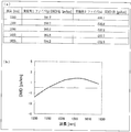
本実施形態に係る光伝送路Fの実施例(実施例6)について、図14(a)および図14(b)を参照して説明する。図14(a)は、実施例6の光伝送路Fにおける、光ファイバFp,Fnのモード分散Δτを示す。図14(b)は、実施例6における光伝送路Fの、モード分散特性を示すグラフである。
本実施形態に係る光伝送路Fの実施例(実施例6)について、図14(a)および図14(b)を参照して説明する。図14(a)は、実施例6の光伝送路Fにおける、光ファイバFp,Fnのモード分散Δτを示す。図14(b)は、実施例6における光伝送路Fの、モード分散特性を示すグラフである。
本実施例6では、実施例1の光ファイバ1を光ファイバFpとして用い、実施例2の光ファイバ1を光ファイバFnとして用い、光伝送路Fを構成した。すなわち、本実施例6では、1530~1625nm帯においてモード分散Δτが略一定である光ファイバFp,Fpを用い、光伝送路Fを構成した。各光ファイバのモード分散Δτは、図14(a)に示すとおりである。
そして、本実施例6では、λ=1580nm(光ファイバFpのモード分散Δτ=295.0ps/km、光ファイバFnのモード分散Δτ=-532.2ps/km)において、光伝送路Fのモード分散Δτが0となるように、Lp(光ファイバFpのファイバ長)と、Ln(光ファイバFnのファイバ長)との比をLp:Ln=0.645:0.355に設定し、光伝送路Fのモード分散特性を求めた。
図14(b)に示すように、実施例6の光伝送路Fは、1530~1625nm帯において、モード分散Δτは、-2~2ps/kmとなり、モード分散Δτが極めて小さく、且つ、モード分散Δτの波長λによる影響が極めて小さいものであることが確認された。したがって、実施例5の光ファイバ1は、1530~1625nm帯全域に亘って、モード分散を十分に補償することができるものであることが確認された。
〔比較例1〕
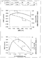
本実施形態に係る光ファイバ1の比較例について、図15~図17を参照して説明する。図15は、本比較例の光ファイバにおける、屈折率分布を規定する各パラメータの設定値を示す。図16は、本比較例に係る光ファイバの、モード分散特性を示すグラフである。
本実施形態に係る光ファイバ1の比較例について、図15~図17を参照して説明する。図15は、本比較例の光ファイバにおける、屈折率分布を規定する各パラメータの設定値を示す。図16は、本比較例に係る光ファイバの、モード分散特性を示すグラフである。
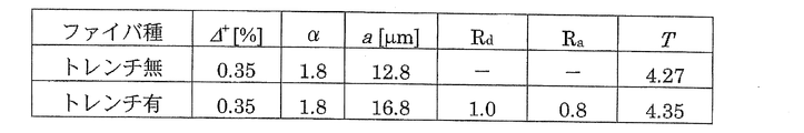
本比較例では、トレンチ無の光ファイバと、トレンチ有の光ファイバとを用いた。そして、図15に示すように、トレンチ無の光ファイバには、α=1.8、Δ+=0.35を設定した。また、トレンチ有の光ファイバには、Ra=0.8、Rd=1.0、α=1.8、Δ+=0.35を設定した。
この結果、図16(a)に示すように、上記トレンチ無の光ファイバは、1530~1625nm帯において、モード分散Δτは、-600~-460ps/kmとなり、モード分散Δτの波長λに対する傾きdΔτ/dλは、|1.7|ps/km/nm以下となり、各実施例の光ファイバ1と比べて、上記傾きが大きいものとなった。
また、図16(b)に示すように、上記トレンチ有の光ファイバは、1530~1625nm帯において、モード分散Δτは、305~385ps/kmとなり、モード分散Δτの波長λに対する傾きdΔτ/dλは、|0.8|ps/km/nm以下となり、各実施例の光ファイバ1と比べて、上記傾きが大きいものとなった。
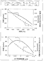
ここで、本比較例の光ファイバにおいて、コア半径の変動がモード分散特性に及ぼす影響について、図17を参照して説明する。図17は、本比較例に係る光ファイバに関して、コア半径の変動量とモード分散特性との関係を示すグラフである。
図17(a)に示すように、上記トレンチ無の光ファイバは、コア半径に対するモード分散Δτの傾きが、|190|ps/km/μm以下であり、コア径の変動によるモード分散の影響が、各実施例の光ファイバ1と比べて大きいものであることが確認された。
また、図17(b)に示すように、上記トレンチ有の光ファイバは、コア半径に対するモード分散Δτの傾きが、|80|ps/km/μm以下であり、コア径の変動によるモード分散の影響が、各実施例の光ファイバ1と比べて大きいものであることが確認された。
〔付記事項〕
本発明は上述した各実施形態に限定されるものではなく、請求項に示した範囲で種々の変更が可能であり、異なる実施形態にそれぞれ開示された技術的手段を適宜組み合わせて得られる実施形態についても本発明の技術的範囲に含まれる。
本発明は上述した各実施形態に限定されるものではなく、請求項に示した範囲で種々の変更が可能であり、異なる実施形態にそれぞれ開示された技術的手段を適宜組み合わせて得られる実施形態についても本発明の技術的範囲に含まれる。
なお、上記各実施形態では、モード分散の補償対象とする波長帯域を、1530~1625nm帯としたが、これに限らない。本発明が他の波長帯域をモード分散の補償対象とすることが可能なことは、当業者からしてみれば本書の内容から明らかである。
〔まとめ〕
以上のように、本発明の一態様に係る光ファイバは、信号光に含まれるLP01モード成分およびLP11モード成分を伝搬する2モード光ファイバであって、予め定められた波長帯域において、上記数式(2)により定義されるモード分散Δτが一定であることを特徴とする。上記数式(2)において、vg11は、前記LP11モード成分の群速度を示し、vg01は、前記LP01モード成分の群速度を示す。
以上のように、本発明の一態様に係る光ファイバは、信号光に含まれるLP01モード成分およびLP11モード成分を伝搬する2モード光ファイバであって、予め定められた波長帯域において、上記数式(2)により定義されるモード分散Δτが一定であることを特徴とする。上記数式(2)において、vg11は、前記LP11モード成分の群速度を示し、vg01は、前記LP01モード成分の群速度を示す。
特に、上記光ファイバにおいて、前記波長帯域において、波長λに対する前記モード分散Δτの傾きdΔτ/dλが、|0.5|ps/km/nm以下であることが好ましい。特に、1530~1625nm帯である前記波長帯域において、波長λに対する前記モード分散Δτの傾きdΔτ/dλが、|0.5|ps/km/nm以下であることが好ましい。
上記各光ファイバによれば、波長λによるモード分散特性の変動が殆ど生じないため、符号が正であるモード分散特性を持つ第1の光ファイバと、符号が負であるモード分散特性を持つ第2の光ファイバとの各々を、当該光ファイバのように構成し、さらに、上記第1の光ファイバと上記第2の光ファイバとを適切な長さで組み合わせることにより、広い波長帯域に亘ってモード分散補償がなされた光伝送路を実現することができる。特に、上記光ファイバにより、本書に記載した実験結果からも明らかなように、通信波長帯である1530~1625nm帯(但し、これに限定するものではない。)の全域に亘ってモード分散補償がなされた、光伝送路を実現することができ、よって、上記光ファイバがより有用なものであることがわかる。
上記光ファイバにおいて、屈折率分布がα乗型であり、最大屈折率がn1である内側コアと、上記内側コアを取り囲み、且つ、屈折率がn1’である外側コアと、上記外側コアを取り囲み、且つ、屈折率がn2(n1’<n2<n1)であるクラッドとを備えることが好ましい。特に、上記光ファイバにおいて、前記内側コアの半径をr1とし、前記外側コアの外周部の半径をaとし、前記外側コアと前記クラッドとの比屈折率差をΔ-とし、前記内側コアと前記クラッドとの比屈折率差をΔ+とし、Ra=r1/aとし、Rd=|Δ-|/|Δ+|とした場合において、以下の条件1~3を満たすことが好ましい。
(条件1):Ra≦0.7
(条件2):0.1<Rd<0.5
(条件3):1.0≦α≦10.0
この光ファイバによれば、上記各パラメータを適切に調整することにより、モード分散Δτの波長λおよびコア半径aに対する傾きdΔτ/dλおよびdΔτ/daが極めて小さい、つまり、波長λおよびコア径の影響が極めて小さいモード分散特性を、より確実に得ることができる。
(条件2):0.1<Rd<0.5
(条件3):1.0≦α≦10.0
この光ファイバによれば、上記各パラメータを適切に調整することにより、モード分散Δτの波長λおよびコア半径aに対する傾きdΔτ/dλおよびdΔτ/daが極めて小さい、つまり、波長λおよびコア径の影響が極めて小さいモード分散特性を、より確実に得ることができる。
また、本発明の一態様に係る光伝送路は、上記光ファイバを用いており、且つ、前記モード分散Δτの符号が正である第1の光ファイバと、上記光ファイバを用いており、且つ、前記モード分散Δτの符号が負である第2の光ファイバとを備えていることを特徴とする。
この光伝送路によれば、所望の波長帯域の全域に亘って、モード分散を十分に補償することができる光伝送路を実現することができる。
本発明は、通信用の光伝送路に利用可能であり、特に、波長多重分割又はモード多重分割による通信用の光伝送路に好適に利用することができる。
F 光伝送路
Fp 光ファイバ(第1の光ファイバ)
Fn 光ファイバ(第2の光ファイバ)
1 光ファイバ
11 コア
111 内側コア
112 外側コア
12 クラッド
Fp 光ファイバ(第1の光ファイバ)
Fn 光ファイバ(第2の光ファイバ)
1 光ファイバ
11 コア
111 内側コア
112 外側コア
12 クラッド
Claims (6)
- 信号光に含まれるLP01モード成分およびLP11モード成分を伝搬する2モード光ファイバであって、
予め定められた波長帯域において、下記数式(2)により定義されるモード分散Δτが一定である
ことを特徴とする光ファイバ。

- 前記波長帯域において、
波長λに対する前記モード分散Δτの傾きdΔτ/dλが、|0.5|ps/km/nm以下
であることを特徴とする請求項1に記載の光ファイバ。 - 1530~1625nm帯である前記波長帯域において、
波長λに対する前記モード分散Δτの傾きdΔτ/dλが、|0.5|ps/km/nm以下
であることを特徴とする請求項2に記載の光ファイバ。 - 屈折率分布がα乗型であり、最大屈折率がn1である内側コアと、
上記内側コアを取り囲み、且つ、屈折率がn1’である外側コアと、
上記外側コアを取り囲み、且つ、屈折率がn2(n1’<n2<n1)であるクラッドと
を備えることを特徴とする請求項1から3のいずれか1項に記載の光ファイバ。 - 前記内側コアの半径をr1とし、
前記外側コアの外周部の半径をaとし、
前記外側コアと前記クラッドとの比屈折率差をΔ-とし、
前記内側コアと前記クラッドとの比屈折率差をΔ+とし、
Ra=r1/aとし、
Rd=|Δ-|/|Δ+|とした場合において、
以下の条件1~3を満たすことを特徴とする請求項4に記載の光ファイバ。
(条件1):Ra≦0.7
(条件2):0.1<Rd<0.5
(条件3):1.0≦α≦10.0 - 請求項1から5のいずれか1項に記載の光ファイバを用いており、且つ、前記モード分散Δτの符号が正である第1の光ファイバと、
請求項1から5のいずれか1項に記載の光ファイバを用いており、且つ、前記モード分散Δτの符号が負である第2の光ファイバと
を備えていることを特徴とする光伝送路。
Priority Applications (4)
| Application Number | Priority Date | Filing Date | Title |
|---|---|---|---|
| DK14757019.6T DK2871502T3 (en) | 2013-03-01 | 2014-02-05 | OPTICAL FIBER AND OPTICAL TRANSMISSION PIPE |
| EP14757019.6A EP2871502B1 (en) | 2013-03-01 | 2014-02-05 | Optical fiber and optical transmission line |
| CN201480002049.9A CN104520739B (zh) | 2013-03-01 | 2014-02-05 | 光纤以及光传输路 |
| US14/419,738 US9507082B2 (en) | 2013-03-01 | 2014-02-05 | Two-mode optical fiber and light transmission path |
Applications Claiming Priority (2)
| Application Number | Priority Date | Filing Date | Title |
|---|---|---|---|
| JP2013-041253 | 2013-03-01 | ||
| JP2013041253A JP5789626B2 (ja) | 2013-03-01 | 2013-03-01 | 光ファイバおよび光伝送路 |
Publications (1)
| Publication Number | Publication Date |
|---|---|
| WO2014132763A1 true WO2014132763A1 (ja) | 2014-09-04 |
Family
ID=51428037
Family Applications (1)
| Application Number | Title | Priority Date | Filing Date |
|---|---|---|---|
| PCT/JP2014/052693 Ceased WO2014132763A1 (ja) | 2013-03-01 | 2014-02-05 | 光ファイバおよび光伝送路 |
Country Status (6)
| Country | Link |
|---|---|
| US (1) | US9507082B2 (ja) |
| EP (1) | EP2871502B1 (ja) |
| JP (1) | JP5789626B2 (ja) |
| CN (1) | CN104520739B (ja) |
| DK (1) | DK2871502T3 (ja) |
| WO (1) | WO2014132763A1 (ja) |
Cited By (1)
| Publication number | Priority date | Publication date | Assignee | Title |
|---|---|---|---|---|
| WO2016147806A1 (ja) * | 2015-03-13 | 2016-09-22 | 株式会社フジクラ | 光ファイバおよび光ファイバの製造方法 |
Families Citing this family (1)
| Publication number | Priority date | Publication date | Assignee | Title |
|---|---|---|---|---|
| EP3047317B1 (en) * | 2013-09-20 | 2018-01-31 | Draka Comteq BV | Few mode optical fiber links for space division multiplexing |
Citations (1)
| Publication number | Priority date | Publication date | Assignee | Title |
|---|---|---|---|---|
| JP2006221052A (ja) | 2005-02-14 | 2006-08-24 | Fujikura Ltd | マルチモード分散補償ファイバ、モード分散の補償方法、光導波路、光伝送路及び光通信システム |
Family Cites Families (8)
| Publication number | Priority date | Publication date | Assignee | Title |
|---|---|---|---|---|
| US4877304A (en) | 1987-09-09 | 1989-10-31 | Corning Incorporated | Few-mode/single-mode fiber |
| US4889404A (en) | 1987-09-09 | 1989-12-26 | Corning Incorporated | Asymmetrical bidirectional telecommunication system |
| JP3910486B2 (ja) * | 2002-05-17 | 2007-04-25 | 株式会社フジクラ | 光ファイバ及び光伝送路 |
| CN101006372B (zh) * | 2004-08-30 | 2010-09-08 | 株式会社藤仓 | 单模光纤 |
| FR2933779B1 (fr) * | 2008-07-08 | 2010-08-27 | Draka Comteq France | Fibres optiques multimodes |
| WO2012108467A1 (ja) * | 2011-02-09 | 2012-08-16 | 古河電気工業株式会社 | 光ファイバおよび光伝送システム |
| EP2584388B1 (en) * | 2011-10-20 | 2018-09-19 | Draka Comteq BV | Method of computing an effective bandwidth of a multimode fiber |
| IN2014DN07356A (ja) * | 2012-02-20 | 2015-04-24 | Corning Inc |
-
2013
- 2013-03-01 JP JP2013041253A patent/JP5789626B2/ja active Active
-
2014
- 2014-02-05 DK DK14757019.6T patent/DK2871502T3/en active
- 2014-02-05 WO PCT/JP2014/052693 patent/WO2014132763A1/ja not_active Ceased
- 2014-02-05 CN CN201480002049.9A patent/CN104520739B/zh active Active
- 2014-02-05 US US14/419,738 patent/US9507082B2/en active Active
- 2014-02-05 EP EP14757019.6A patent/EP2871502B1/en active Active
Patent Citations (1)
| Publication number | Priority date | Publication date | Assignee | Title |
|---|---|---|---|---|
| JP2006221052A (ja) | 2005-02-14 | 2006-08-24 | Fujikura Ltd | マルチモード分散補償ファイバ、モード分散の補償方法、光導波路、光伝送路及び光通信システム |
Non-Patent Citations (6)
| Title |
|---|
| RYO MARUYAMA ET AL.: "A Study on Design of Two-Mode Optical Fiber for Bundle Transmission", 2011 NEN IEICE COMMUNICATIONS SOCIETY CONFERENCE KOEN RONBUNSHU 2, 30 August 2011 (2011-08-30), pages 235, XP008170257 * |
| RYO MARUYAMA ET AL.: "DMD Free Transmission Line Composed of TMFs with Large Effective Area for MIMO Processing", ECOC 2012, 16 September 2012 (2012-09-16), pages 1 - 3, XP032543782 * |
| RYO MARUYAMA ET AL.: "DMD Free Transmission Line Composed of TMFs with Large Effective Area for MIMO Processing", ECOC2012, TU.L.F.2, 16 June 2012 (2012-06-16) |
| See also references of EP2871502A4 * |
| TAIJI SAKAMOTO ET AL.: "Differential Mode Delay Managed Transmission Line for Wide-band WDM-MIMO System", OFC 2012, OM2D.1 1, 4 March 2012 (2012-03-04) |
| TAIJI SAKAMOTO ET AL.: "Differential Mode Delay Managed Transmission Line for Wide-band WDM-MIMO System", OFC/NFOEC 2012, 4 March 2012 (2012-03-04), pages 1 - 3, XP032340452 * |
Cited By (4)
| Publication number | Priority date | Publication date | Assignee | Title |
|---|---|---|---|---|
| WO2016147806A1 (ja) * | 2015-03-13 | 2016-09-22 | 株式会社フジクラ | 光ファイバおよび光ファイバの製造方法 |
| JP2016170356A (ja) * | 2015-03-13 | 2016-09-23 | 株式会社フジクラ | 光ファイバおよび光ファイバの製造方法 |
| CN106461857A (zh) * | 2015-03-13 | 2017-02-22 | 株式会社藤仓 | 光纤以及光纤的制造方法 |
| CN106461857B (zh) * | 2015-03-13 | 2019-10-01 | 株式会社藤仓 | 光纤以及光纤的制造方法 |
Also Published As
| Publication number | Publication date |
|---|---|
| JP5789626B2 (ja) | 2015-10-07 |
| CN104520739A (zh) | 2015-04-15 |
| EP2871502A4 (en) | 2015-07-15 |
| EP2871502B1 (en) | 2016-11-16 |
| JP2014170078A (ja) | 2014-09-18 |
| EP2871502A1 (en) | 2015-05-13 |
| CN104520739B (zh) | 2018-01-30 |
| US9507082B2 (en) | 2016-11-29 |
| US20150212265A1 (en) | 2015-07-30 |
| DK2871502T3 (en) | 2017-01-23 |
Similar Documents
| Publication | Publication Date | Title |
|---|---|---|
| CA2277332C (en) | Dispersion-flattened optical fiber | |
| JP6397899B2 (ja) | 空間分割多重のための少モード光ファイバ光リンク | |
| CN108700703B (zh) | 模分复用所用的少模光纤 | |
| JP6397898B2 (ja) | 空間分割多重のための少モード光ファイバ | |
| JP5193398B2 (ja) | 光ファイバおよび光伝送システム | |
| EP2362252A1 (en) | Optical fiber and optical communication system including same | |
| JPWO2015133407A1 (ja) | マルチコアファイバ | |
| JP4851371B2 (ja) | 光ファイバおよび光ファイバ伝送路 | |
| JP6659847B2 (ja) | モード間損失差補償器及び光増幅器 | |
| JP6734374B2 (ja) | 光ファイバ及び光伝送システム | |
| DK2690473T3 (en) | Optical fiber and optical transmission line | |
| JP5789626B2 (ja) | 光ファイバおよび光伝送路 | |
| CN109073825B (zh) | 模分复用所用的少模光纤 | |
| JP6092029B2 (ja) | マルチモード光ファイバおよび光ファイバ伝送システム | |
| US7164832B2 (en) | Optical fiber and optical communication system employing the optical fiber | |
| JP5937974B2 (ja) | マルチモード光ファイバおよび光ファイバ伝送システム | |
| JP6654064B2 (ja) | モード変換器、光増幅器及び光伝送システム | |
| JP5486138B2 (ja) | 光ファイバ、及び、光伝送路 | |
| JP2015212757A (ja) | 数モード光ファイバおよび数モード光ファイバの設計方法 | |
| JP2014002297A (ja) | マルチモード光ファイバ及びマルチモード光ファイバ設計方法 | |
| JP2008257165A (ja) | 光ファイバおよび光ファイバ伝送路 |
Legal Events
| Date | Code | Title | Description |
|---|---|---|---|
| 121 | Ep: the epo has been informed by wipo that ep was designated in this application |
Ref document number: 14757019 Country of ref document: EP Kind code of ref document: A1 |
|
| REEP | Request for entry into the european phase |
Ref document number: 2014757019 Country of ref document: EP |
|
| WWE | Wipo information: entry into national phase |
Ref document number: 2014757019 Country of ref document: EP |
|
| WWE | Wipo information: entry into national phase |
Ref document number: 14419738 Country of ref document: US |
|
| NENP | Non-entry into the national phase |
Ref country code: DE |