WO2014133037A1 - 真空断熱材 - Google Patents
真空断熱材 Download PDFInfo
- Publication number
- WO2014133037A1 WO2014133037A1 PCT/JP2014/054755 JP2014054755W WO2014133037A1 WO 2014133037 A1 WO2014133037 A1 WO 2014133037A1 JP 2014054755 W JP2014054755 W JP 2014054755W WO 2014133037 A1 WO2014133037 A1 WO 2014133037A1
- Authority
- WO
- WIPO (PCT)
- Prior art keywords
- heat insulating
- insulating material
- vacuum heat
- main plane
- vacuum
- Prior art date
- Legal status (The legal status is an assumption and is not a legal conclusion. Google has not performed a legal analysis and makes no representation as to the accuracy of the status listed.)
- Ceased
Links
Images



Classifications
-
- B—PERFORMING OPERATIONS; TRANSPORTING
- B32—LAYERED PRODUCTS
- B32B—LAYERED PRODUCTS, i.e. PRODUCTS BUILT-UP OF STRATA OF FLAT OR NON-FLAT, e.g. CELLULAR OR HONEYCOMB, FORM
- B32B3/00—Layered products comprising a layer with external or internal discontinuities or unevennesses, or a layer of non-planar shape; Layered products comprising a layer having particular features of form
- B32B3/02—Layered products comprising a layer with external or internal discontinuities or unevennesses, or a layer of non-planar shape; Layered products comprising a layer having particular features of form characterised by features of form at particular places, e.g. in edge regions
- B32B3/04—Layered products comprising a layer with external or internal discontinuities or unevennesses, or a layer of non-planar shape; Layered products comprising a layer having particular features of form characterised by features of form at particular places, e.g. in edge regions characterised by at least one layer folded at the edge, e.g. over another layer ; characterised by at least one layer enveloping or enclosing a material
-
- B—PERFORMING OPERATIONS; TRANSPORTING
- B60—VEHICLES IN GENERAL
- B60R—VEHICLES, VEHICLE FITTINGS, OR VEHICLE PARTS, NOT OTHERWISE PROVIDED FOR
- B60R13/00—Elements for body-finishing, identifying, or decorating; Arrangements or adaptations for advertising purposes
- B60R13/02—Internal Trim mouldings ; Internal Ledges; Wall liners for passenger compartments; Roof liners
- B60R13/0212—Roof or head liners
-
- B—PERFORMING OPERATIONS; TRANSPORTING
- B32—LAYERED PRODUCTS
- B32B—LAYERED PRODUCTS, i.e. PRODUCTS BUILT-UP OF STRATA OF FLAT OR NON-FLAT, e.g. CELLULAR OR HONEYCOMB, FORM
- B32B27/00—Layered products comprising a layer of synthetic resin
- B32B27/30—Layered products comprising a layer of synthetic resin comprising vinyl (co)polymers; comprising acrylic (co)polymers
- B32B27/306—Layered products comprising a layer of synthetic resin comprising vinyl (co)polymers; comprising acrylic (co)polymers comprising vinyl acetate or vinyl alcohol (co)polymers
-
- F—MECHANICAL ENGINEERING; LIGHTING; HEATING; WEAPONS; BLASTING
- F16—ENGINEERING ELEMENTS AND UNITS; GENERAL MEASURES FOR PRODUCING AND MAINTAINING EFFECTIVE FUNCTIONING OF MACHINES OR INSTALLATIONS; THERMAL INSULATION IN GENERAL
- F16L—PIPES; JOINTS OR FITTINGS FOR PIPES; SUPPORTS FOR PIPES, CABLES OR PROTECTIVE TUBING; MEANS FOR THERMAL INSULATION IN GENERAL
- F16L59/00—Thermal insulation in general
- F16L59/06—Arrangements using an air layer or vacuum
- F16L59/065—Arrangements using an air layer or vacuum using vacuum
-
- B—PERFORMING OPERATIONS; TRANSPORTING
- B32—LAYERED PRODUCTS
- B32B—LAYERED PRODUCTS, i.e. PRODUCTS BUILT-UP OF STRATA OF FLAT OR NON-FLAT, e.g. CELLULAR OR HONEYCOMB, FORM
- B32B2262/00—Composition or structural features of fibres which form a fibrous or filamentary layer or are present as additives
- B32B2262/10—Inorganic fibres
- B32B2262/101—Glass fibres
-
- B—PERFORMING OPERATIONS; TRANSPORTING
- B32—LAYERED PRODUCTS
- B32B—LAYERED PRODUCTS, i.e. PRODUCTS BUILT-UP OF STRATA OF FLAT OR NON-FLAT, e.g. CELLULAR OR HONEYCOMB, FORM
- B32B2307/00—Properties of the layers or laminate
- B32B2307/30—Properties of the layers or laminate having particular thermal properties
- B32B2307/304—Insulating
-
- B—PERFORMING OPERATIONS; TRANSPORTING
- B32—LAYERED PRODUCTS
- B32B—LAYERED PRODUCTS, i.e. PRODUCTS BUILT-UP OF STRATA OF FLAT OR NON-FLAT, e.g. CELLULAR OR HONEYCOMB, FORM
- B32B2307/00—Properties of the layers or laminate
- B32B2307/30—Properties of the layers or laminate having particular thermal properties
- B32B2307/31—Heat sealable
-
- B—PERFORMING OPERATIONS; TRANSPORTING
- B32—LAYERED PRODUCTS
- B32B—LAYERED PRODUCTS, i.e. PRODUCTS BUILT-UP OF STRATA OF FLAT OR NON-FLAT, e.g. CELLULAR OR HONEYCOMB, FORM
- B32B2419/00—Buildings or parts thereof
- B32B2419/06—Roofs, roof membranes
-
- B—PERFORMING OPERATIONS; TRANSPORTING
- B32—LAYERED PRODUCTS
- B32B—LAYERED PRODUCTS, i.e. PRODUCTS BUILT-UP OF STRATA OF FLAT OR NON-FLAT, e.g. CELLULAR OR HONEYCOMB, FORM
- B32B2605/00—Vehicles
- B32B2605/08—Cars
Definitions
- the present invention relates to a vacuum heat insulating material.
- the present invention relates to a vacuum heat insulating material that can maintain a vacuum over a long period of time even when used in a high temperature range.
- Patent Document 1 discloses an outer skin in which a barrier layer, an inner protective layer, and an outer protective layer are sequentially laminated on the outer side of a heat sealing layer.
- Patent Document 2 discloses that a film is further provided on the outside of the vacuum heat insulating material, and Patent Document 3 discloses that a second heat-sealing is performed further outside after the sealing portion is heat-sealed. It is disclosed.
- Such vacuum heat insulating materials are widely used in home appliances, particularly refrigerators, as heat insulating materials that enhance energy saving effects for the purpose of preventing global warming due to carbon dioxide emissions. They are also commercialized on the lids and even on the outer walls of houses.
- the vacuum heat insulating material is used at normal temperature or a temperature range slightly higher than normal temperature.
- the vacuum heat insulating material is exposed to the temperature in the room and the temperature in the refrigerator.
- the temperature to which the vacuum heat insulating material is exposed is expected to be lower than the hot water supply temperature that is approximately 42 ° C. or less.
- the walls of the house are exposed to temperatures of up to about 40 ° C, depending on the direction and location.
- the use of the vacuum heat insulating material is widespread in a relatively low temperature range, but is not widely used in a high temperature range (over 60 ° C. and up to about 100 ° C.).
- the roof surface is said to reach nearly 100 ° C in the summer, and it is said that the roof of houses also reaches about 60 ° C in the summer, and the hot water temperature in the hot water tank is about 90 ° C.
- the use of vacuum heat insulating materials is limited in such applications.
- an object of the present invention is to provide a vacuum heat insulating material capable of maintaining a vacuum over a long period of time in a high temperature region.
- the inventors of the present invention have found that when the vacuum heat insulating material is used in a high temperature range, the vacuum of the vacuum heat insulating material is easily broken from the sealed portion, and the vacuum breaks due to the high temperature of the sealed portion. We found that the speed of the increased rapidly. And when the present inventors use a vacuum heat insulating material in a high temperature region, the vacuum breakage due to heating of the sealing portion is prevented by positioning the position of this sealing portion on the low temperature side of the vacuum heat insulating material, thereby The inventors have found that a vacuum can be maintained for an extremely long time, and have reached the present invention. That is, the present invention is as follows.
- a vacuum heat insulating material having a core material and a skin enclosing the core material,
- the outer skin includes a heat-seal layer, and the heat-seal layers facing each other at an end thereof are heat-sealed to form a sealing part
- the core has a first main plane that is exposed to a relatively high temperature side during use, and a second main plane that faces the first main plane and is exposed to a relatively low temperature side during use.
- At least a part of the sealing portion is a vacuum heat insulating material located on the second main plane side.
- the outer skin is folded at the end surface of the core member to be positioned on the second main plane side, and the length of the folded portion of the outer shell is 10 to 100 mm starting from the end surface of the core member.
- [3] The vacuum heat insulating material according to [1] or [2], wherein the entire sealing portion is located on the second main plane side.
- [4] The vacuum heat insulation according to [1] to [3], wherein a plurality of the sealing portions are formed on the outer skin, and the plurality of the sealing portions are all located on the second main plane side. Wood.
- the vacuum heat insulating material of the present invention can maintain a vacuum for an extremely long time even when used in a high temperature range. Moreover, since the vacuum heat insulating material of this invention can maintain a vacuum over a long period of time, a vacuum heat insulating material can be made thin.
- the vacuum heat insulating material of the present invention has a core material and an outer skin enclosing the core material, the outer skin includes a heat-sealing layer, and the heat-sealing layers facing each other at the ends are heat-sealed to each other.
- the sealing part is formed.
- the core has a first main plane that is exposed to the relatively high temperature side during use, and a second main plane that faces the first main plane and is exposed to the relatively low temperature side during use, At least a part of the sealing portion is located on the second main plane.
- the vacuum heat insulating material encloses the core material in the outer skin, and the inside of the outer skin is deaerated to be in a vacuum state.
- the heat fusion layers of the outer skin are laminated to face each other, and the peripheral edges in three directions except for one end serving as an opening are heat-sealed to form a sealing portion, and the outer skin is formed into a bag shape.
- the core material is accommodated from the opening of the bag-shaped outer skin, and the outer skin is brought into a vacuum state so that the outer skin is brought into close contact with the core material, and then the opening is heat-sealed to form a sealing portion.
- a vacuum heat insulating material can be obtained.
- the outer skin formed with sealing portions at both ends is longer than the core material to form an ear portion, and the ear portion of the outer skin is folded at the end surface of the core material.
- at least a part of the sealing portion is positioned on the low temperature side of the vacuum heat insulating material. That is, when using a vacuum heat insulating material, the surface of the core material on the side where the vacuum heat insulating material is exposed to a high temperature is defined as the first main plane, and the opposite surface facing this surface is defined as the second main plane.
- at least a portion of the sealing portion is located on the second main plane.
- the whole sealing part is located on the second main plane side.
- a plurality of the sealing portions may be formed in the ear portion of the outer skin, and more preferably, the plurality of sealing portions are all located on the second main plane side. According to this, vacuum breakage due to heating of the sealing portion can be prevented, and the vacuum can be maintained for a very long time even when the vacuum heat insulating material is used in a high temperature region.
- the high temperature is a temperature of 40 ° C. or higher, 50 ° C. or higher, 60 ° C. or higher, 70 ° C. or higher, or 100 ° C. or higher.
- the relatively high temperature side means the side that reaches the maximum temperature during use, and the relatively low temperature side means the opposite side. That is, in the automobile, the outdoor side becomes hot due to the outside air temperature and solar radiation in summer, and the interior of the vehicle is warm due to heating in winter. Even in such a case, the high temperature side that reaches the maximum temperature is the outdoor side of the automobile.
- the length of the folded portion of the outer skin formed by folding the ears of the outer skin at the end surface of the core material is 10 mm or more and 100 mm or less from the end surface of the core material. It is. If this length is sufficient, it is difficult for heat to be transmitted to the sealing portion, and if this length is not more than the above range, it is possible to prevent excessive deterioration of heat insulation due to an increase in the outer skin.
- the folded portion of the outer skin may be at least partially fixed with an adhesive or the like, and the entire outer skin is further wrapped with another member to fix the folded portion of the outer skin on the second main plane. You can also.
- the length of the folded portion of the outer skin is preferably 15 mm or more, and more preferably 20 mm or more. Further, the length of the folded portion of the outer skin is preferably 80 mm or less, and more preferably 50 mm or less.
- the surface of the first main plane side and the second main plane side of the vacuum heat insulating material can be given different indications and / or colors so as to be easily understood at the time of construction. For example, an indication that the first main plane side is used on the high temperature side and / or an indication that the second main plane side is used on the low temperature side are preferable.
- the first main plane side and the second main plane side of the vacuum heat insulating material can have different marks, different colors, or different notations.
- an indication that it is used indoors on the second main plane side and / or an indication that it is used on the first main plane side shall be attached. Can do.
- the indication of being used outside can be given to the 2nd main plane side, and / or the indication of being used inside can be given to the 1st main plane side.
- the actual display includes “high temperature side”, “low temperature side”, “high temperature”, “low temperature”, “high”, “low”, “inside”, “outside”, “inside”, “outside” ”,“ Inside ”,“ outside ”, and the like, but are not limited thereto.
- the core material used for the vacuum heat insulating material of the present invention is not particularly limited as long as it has heat insulating properties.
- the core material include pearlite powder, silica powder, precipitated silica powder, diatomaceous earth, calcium silicate, glass wool, rock wool, and resin foam (for example, styrene foam and urethane foam).
- Glass wool is preferable. More preferably, a glass wool molded body is used.
- a hollow container made of resin or inorganic material, a honeycomb structure, or the like may be used as the core material.
- the fiber diameter of glass wool is preferably 2 to 8 ⁇ m, more preferably 3 to 5 ⁇ m. If the fiber diameter is 2 ⁇ m or more, the energy basic unit required for fiberization is suitable, and if the fiber diameter is 8 ⁇ m or less, the thermal conductivity when fiberized is in a suitable range.
- the density of the glass wool molded product is preferably 50 to 300 kg / m 3 , more preferably 60 to 100 kg / m 3 .
- the thickness of the glass wool molded product is preferably 5 to 30 mm, more preferably 10 to 20 mm.
- the thickness of the glass wool molded body is large, it is preferable because the internal pressure is less likely to increase by the increase in volume even when gas flows into the vacuum heat insulating material.
- the handling is easy. preferable.
- the vacuum heat insulating material may include an adsorbent or getter material that adsorbs water vapor or gas in the outer skin together with the core material.
- adsorbent or getter material that adsorbs water vapor or gas in the outer skin together with the core material.
- Examples include physical adsorbents such as zeolite, activated carbon, activated alumina, silica gel, dosonite, and hydrotalcite, and chemical adsorbents such as alkali metals and alkaline earth metals alone and their oxides and hydroxides.
- the outer skin usually includes a heat-sealing layer, a barrier layer, and a protective layer, and the heat-sealing layers facing each other at the ends thereof are heat-sealed to form a sealing portion, and the core material is formed.
- Each layer can be bonded together with a layer of adhesive.
- an adsorbent, a hygroscopic agent, etc. can also be contained in each layer and / or each layer.
- the heat-fusible layer from the viewpoint of moldability, polyolefin resin such as linear low density polyethylene, high density polyethylene, and random polypropylene, ethylene-vinyl acetate copolymer, ethylene-vinyl alcohol copolymer, ionomer, Modified products of these resins can be mentioned, but from the viewpoint of further improving gas barrier properties, it is preferable to use an ethylene-vinyl alcohol copolymer resin.
- the thickness of the heat-sealing layer can be 10 to 100 ⁇ m, and preferably 15 to 50 ⁇ m.
- the ethylene-vinyl alcohol copolymer used here preferably has a melting point of 150 ° C. or higher, more preferably 165 ° C. or higher, and further preferably 180 ° C. or higher.
- the ethylene-vinyl alcohol copolymer used here preferably has an oxygen permeability of 100 cc / m 2 ⁇ 24 Hr ⁇ atm or less at 25 ° C. and 90% RH, preferably 50 cc / m 2 ⁇ 24 Hr. -More preferably, it is atm or less.
- Use of such a resin is preferable in that gas permeation from the sealing portion at a high temperature can be reduced.
- the ethylene content of the ethylene-vinyl alcohol copolymer is preferably 10 to 60 mol%, more preferably 15 to 50 mol% or more from the viewpoint of achieving both good stretchability and gas barrier properties. More preferably, it is 25 to 45 mol% or more.
- the ethylene content can be determined by a nuclear magnetic resonance (NMR) method.
- the degree of saponification of the ethylene-vinyl alcohol copolymer is preferably 90 mol% or more, more preferably 95 mol% or more, and 99 mol% or more from the viewpoint of enhancing gas barrier properties. Is more preferable.
- the upper limit is preferably 100 mol%, more preferably 99.99 mol%.
- the ethylene-vinyl alcohol copolymer used for the heat-sealing layer is composed of two or more different ethylene-vinyl alcohol copolymers, the respective ethylene contents or kens calculated from the blending weight ratio are used.
- the degree of conversion is defined as the ethylene content or saponification degree of the ethylene-vinyl alcohol copolymer blend.
- a layer having a high gas barrier property can be used, such as an aluminum foil, an aluminum vapor-deposited plastic film, a plastic film vapor-deposited with an inorganic substance such as silicon oxide or a metal oxide such as aluminum oxide, polyvinyl alcohol, vinylidene chloride, or the like.
- a film having gas barrier properties such as a plastic film coated with a gas barrier composition, an ethylene-vinyl alcohol copolymer film, and MXD nylon can be used.
- an aluminum foil is preferable from the viewpoint of ensuring no long-term gas barrier property without generating pinholes or the like.
- the thickness of the barrier layer can be 3 to 50 ⁇ m, and preferably 5 to 20 ⁇ m.
- a resin film or sheet having excellent mechanical, physical and chemical properties, excellent strength, heat resistance, moisture resistance, pinhole resistance, puncture resistance, etc. can be used.
- a film or sheet of a tough resin such as a polyester resin, a polyamide resin, or a polypropylene resin can be used.
- the protective layer is laminated in order to enhance physical properties such as strength of the outer packaging material, and the lamination order is not limited to the outermost side of the outer skin, and is interposed between the barrier layer and the heat-sealing layer. It is also possible to provide a plurality of protective layers.
- the thickness of the protective layer can be 10 to 50 ⁇ m, and preferably 10 to 30 ⁇ m.
- the vacuum heat insulating material of the present invention is useful for any heat retaining application that requires heat insulation in a high temperature range of 50 ° C. or higher.
- the vacuum heat insulating material of the present invention can be used for heat insulation of automobiles, roofs of buildings (houses and the like), building walls, building ceilings, building floors, hot water tanks and the like.
- reducing the power consumption of an air conditioner is important for reducing the load on the battery, that is, for the travel distance, and it is extremely useful to use the vacuum heat insulating material of the present invention.
- the use to the roof of a building, a wall, etc. is useful for realization of energy saving of a building.
- the present invention can be similarly applied to floor heating, vending machines, unit baths, bathtubs and lids, thermos bottles, refrigerators, cold storages, cold cars, and cold boxes.
- FIG. 1 shows an example of a normal vacuum heat insulating material Y.
- the vacuum heat insulating material Y is formed by enclosing a core material 2 with an outer skin 3.
- the outer skin 3 includes a heat-sealing layer 4, a barrier layer 6, and a protective layer 7, and a sealing portion 5 is formed by heat-sealing the heat-sealing layers 4 facing each other at the ends thereof.
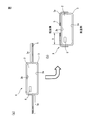
- FIG. 2 is an example of the vacuum heat insulating material X of the present invention, and the ear portion 3a of the outer skin 3 is folded at the end surface of the core material 2 as shown in FIGS. 2 (a) to 2 (b).
- the sealing part 5 is located on the second main plane 2b exposed to the low temperature side during use.
- the length 9 of the folded portion of the outer skin is the distance from the end surface of the core material to the end of the folded ear portion 3a.
- the outer skin 3 encloses the adsorbent 8 together with the core material 2, and the core material 2 has a first main plane 2a exposed to the high temperature side and a second main plane 2b exposed to the low temperature side. Yes.
- FIG. 3 to 5 are usage modes of the vacuum heat insulating material of the present invention.
- the vacuum heat insulating material X of the present invention is used for the roof portion 11 of the automobile 10.
- the sealing portion of the vacuum heat insulating material that is, the second main plane is located on the indoor side of the automobile 10.
- vacuum insulation can be used for doors, floors, and other boundary walls in addition to the roof. If the vacuum heat insulating material is disposed on the surface inside the vehicle, there is a risk of damage to the vacuum heat insulating material by a driver or a passenger. Therefore, it is desirable to dispose the vacuum heat insulating material between the interior material and the outer skin of the automobile.
- the vacuum heat insulating material X of the present invention is used for the roof of the house 20, but the vacuum heat insulating material is inserted between the roof material 21, the field board 22, and the rafters 23.
- the sealing part of a vacuum heat insulating material is located in the inside of a house.
- the vacuum insulation material of the present invention is useful because the roof becomes hot due to the effects of solar radiation like automobiles, but the maximum temperature is also applied to parts such as walls and floors in addition to the roof.
- the vacuum heat insulating material of the present invention can be applied by arranging a sealing part on the opposite side of the side.
- FIG. 5 uses the vacuum heat insulating material X of the present invention around the hot water tank 30.
- the sealing part of the vacuum heat insulating material is located outside the hot water supply tank.
- the hot water tank is generally cylindrical, and when directly attaching a vacuum heat insulating material, the vacuum heat insulating material with a fiber-based heat insulating material such as glass wool as the core material can be bent by itself, so it is arranged along the tank. be able to.
- the vacuum heat insulating material of the present invention is useful for all types of heat retaining applications that require heat insulation in a high temperature range of 50 ° C. or higher.
- it can be suitably used as a vacuum heat insulating material for automobiles, residential roofs, hot water tanks, and the like. It can also be used in floor heating, vending machines, unit baths, bathtubs and lids, thermos bottles, refrigerators, cold storages, cold cars, and cold boxes.
- Vacuum heat insulating material of the present invention Y Conventional vacuum heat insulating material 2 Core material 2a First main plane 2b Second main plane 3 Outer skin 3a Ear portion 4 Thermal fusion layer 5 Sealing portion 6 Barrier layer 7 Protective layer 8 Adsorbent 9 Length of folded portion of outer skin 10 Automobile 11 Automobile roof 20 Housing 21 Roofing material 22 Base plate 23 Residual rafter 30 Hot water tank
Landscapes
- Engineering & Computer Science (AREA)
- Mechanical Engineering (AREA)
- General Engineering & Computer Science (AREA)
- Thermal Insulation (AREA)
- Physics & Mathematics (AREA)
- Architecture (AREA)
- Acoustics & Sound (AREA)
- Electromagnetism (AREA)
- Civil Engineering (AREA)
- Structural Engineering (AREA)
Abstract
Description
前記外皮は、熱融着層を含み、かつその端部において対向している前記熱融着層が互いに熱融着されて封止部を形成しており、
前記芯材は、使用時に相対的に高温側にさらされる第一主平面、及び前記第一主平面に対向しており、かつ使用時に相対的に低温側にさらされる第二主平面を有し、
前記封止部の少なくとも一部は、前記第二主平面側に位置している、真空断熱材。
[2] 前記外皮が前記芯材の端面で折り返されることで前記第二主平面側に位置しており、前記外皮の折り返し部分の長さは、前記芯材の端面を起点に10mm~100mmである、[1]に記載の真空断熱材。
[3] 前記封止部全体が前記第二主平面側に位置している、[1]又は[2]に記載の真空断熱材。
[4] 前記外皮には複数の前記封止部が形成され、前記複数の前記封止部が全て前記第二主平面側に位置している、[1]~[3]に記載の真空断熱材。
[5] 前記第一主平面及び前記第二主平面に、互いに異なる表示及び/又は色彩が付されている、[1]~[4]に記載の真空断熱材。
[6] 前記芯材は、グラスウール成形体である、[1]~[5]に記載の真空断熱材。
[7] 前記熱融着層は、エチレン-ビニルアルコール共重合体樹脂を含む、[1]~[6]のいずれかに記載の真空断熱材。
[8] 前記エチレン-ビニルアルコール共重合体樹脂は、150℃以上の融点を有する、[7]に記載の真空断熱材。
[9] 前記エチレン-ビニルアルコール共重合体樹脂のエチレン含量が10~60mol%である、[7]又は[8]に記載の真空断熱材。
[10] 前記第一主平面が使用時に40℃以上にさらされる、[1]~[9]に記載の真空断熱材。
[11] 前記第一主平面が使用時に60℃以上にさらされる、[10]に記載の真空断熱材。
[12] 自動車用、住宅の屋根用又は給湯タンク用である、[1]~[11]に記載の真空断熱材。
本発明の真空断熱材に使用される芯材は、断熱性を有するものである限り特に制限はない。芯材としては、パーライト粉末、シリカ粉末、沈降シリカ粉末、ケイソウ土、ケイ酸カルシウム、グラスウール、ロックウール、及び樹脂の発泡体(例えば、スチレンフォーム及びウレタンフォーム)などが挙げられるが、好ましくはグラスウール、より好ましくはグラスウールの成形体が用いられる。また、芯材として、樹脂や無機材料製の中空容器や、ハニカム状構造体などを使用してもよい。
外皮は、通常は、熱融着層、バリヤ層、及び保護層を含み、かつその端部において対向している熱融着層を互いに熱融着させて封止部を形成し、芯材を封入する。各層を、接着剤の層で共に接着させることができる。また、各層間及び/又は各層の内部に、吸着剤、吸湿剤等を含有させることもできる。
本発明の真空断熱材は、50℃以上での高温域で断熱性を必要とするあらゆる保温の用途に有用である。例えば、本発明の真空断熱材は自動車、建築物(住宅など)の屋根、建築物の壁、建築物の天井、建築物の床、給湯タンク等の断熱のために用いることができる。特に、電気自動車においては、エアコンの消費電力を低くすることがバッテリの負荷軽減、つまりは走行距離のために重要であり、本願発明の真空断熱材を用いることは極めて有用である。また、建築物の屋根、壁などへの用途は、建築物の省エネルギー化の実現に有用である。これらの用途ばかりではなく、床暖房、自動販売機、ユニットバス、バスタブやその蓋、魔法瓶、冷蔵庫、保冷庫、保冷車、保冷ボックスにおいても同様に適用できる。
以下では、図を用いて、通常の真空断熱材及び本発明の真空断熱材を特定の態様に関して説明する。
Y 従来の真空断熱材
2 芯材
2a 第一主平面
2b 第二主平面
3 外皮
3a 耳部分
4 熱融着層
5 封止部
6 バリヤ層
7 保護層
8 吸着剤
9 外皮の折り返し部分の長さ
10 自動車
11 自動車の屋根
20 住宅
21 屋根材
22 野地板
23 住宅の垂木
30 給湯タンク
Claims (12)
- 芯材及び前記芯材を封入している外皮を有する真空断熱材であって、
前記外皮は、熱融着層を含み、かつその端部において対向している前記熱融着層が互いに熱融着されて封止部を形成しており、
前記芯材は、使用時に相対的に高温側にさらされる第一主平面、及び前記第一主平面に対向しており、かつ使用時に相対的に低温側にさらされる第二主平面を有し、
前記封止部の少なくとも一部は、前記第二主平面側に位置している、
真空断熱材。 - 前記外皮が前記芯材の端面で折り返されることで前記封止部の少なくとも一部は、前記第二主平面側に位置しており、前記外皮の折り返し部分の長さは、前記芯材の端面を起点に10mm以上である、請求項1に記載の真空断熱材。
- 前記封止部全体が前記第二主平面側に位置している、請求項1又は2に記載の真空断熱材。
- 前記外皮には複数の前記封止部が形成され、前記複数の前記封止部が全て前記第二主平面側に位置している、請求項1~3のいずれか一項に記載の真空断熱材。
- 前記第一主平面及び前記第二主平面に、互いに異なる表示及び/又は色彩が付されている、請求項1~4のいずれか一項に記載の真空断熱材。
- 前記芯材は、グラスウール成形体である、請求項1~5のいずれか一項に記載の真空断熱材。
- 前記熱融着層は、エチレン-ビニルアルコール共重合体樹脂を含む、請求項1~6のいずれか一項に記載の真空断熱材。
- 前記エチレン-ビニルアルコール共重合体樹脂は、150℃以上の融点を有する、請求項7に記載の真空断熱材。
- 前記エチレン-ビニルアルコール共重合体樹脂のエチレン含量が10~60mol%である、請求項7又は8に記載の真空断熱材。
- 前記第一主平面が使用時に40℃以上にさらされる、請求項1~9のいずれか一項に記載の真空断熱材。
- 前記第一主平面が使用時に60℃以上にさらされる、請求項10に記載の真空断熱材。
- 自動車用、住宅の屋根用又は給湯タンク用である、請求項1~11のいずれか一項に記載の真空断熱材。
Priority Applications (5)
| Application Number | Priority Date | Filing Date | Title |
|---|---|---|---|
| KR1020157022158A KR102201266B1 (ko) | 2013-02-26 | 2014-02-26 | 진공 단열재 |
| JP2015502993A JPWO2014133037A1 (ja) | 2013-02-26 | 2014-02-26 | 真空断熱材 |
| US14/769,950 US9855717B2 (en) | 2013-02-26 | 2014-02-26 | Vacuum thermal insulation material technical field |
| EP14757115.2A EP2963329B1 (en) | 2013-02-26 | 2014-02-26 | Vacuum thermal insulation material |
| CN201480009731.0A CN105074313B (zh) | 2013-02-26 | 2014-02-26 | 真空隔热材料 |
Applications Claiming Priority (2)
| Application Number | Priority Date | Filing Date | Title |
|---|---|---|---|
| JP2013-036455 | 2013-02-26 | ||
| JP2013036455 | 2013-02-26 |
Publications (1)
| Publication Number | Publication Date |
|---|---|
| WO2014133037A1 true WO2014133037A1 (ja) | 2014-09-04 |
Family
ID=51428297
Family Applications (1)
| Application Number | Title | Priority Date | Filing Date |
|---|---|---|---|
| PCT/JP2014/054755 Ceased WO2014133037A1 (ja) | 2013-02-26 | 2014-02-26 | 真空断熱材 |
Country Status (6)
| Country | Link |
|---|---|
| US (1) | US9855717B2 (ja) |
| EP (1) | EP2963329B1 (ja) |
| JP (1) | JPWO2014133037A1 (ja) |
| KR (1) | KR102201266B1 (ja) |
| CN (1) | CN105074313B (ja) |
| WO (1) | WO2014133037A1 (ja) |
Cited By (3)
| Publication number | Priority date | Publication date | Assignee | Title |
|---|---|---|---|---|
| JPWO2017047701A1 (ja) * | 2015-09-15 | 2018-06-28 | 株式会社クラレ | 真空断熱材、真空断熱材の製造方法及び真空断熱材用外包材 |
| JP2020085180A (ja) * | 2018-11-29 | 2020-06-04 | 大日本印刷株式会社 | 真空断熱材用外包材、真空断熱材、および真空断熱材付き物品 |
| JP2021124263A (ja) * | 2020-02-07 | 2021-08-30 | 三菱電機株式会社 | 貯湯式給湯機用断熱材 |
Families Citing this family (5)
| Publication number | Priority date | Publication date | Assignee | Title |
|---|---|---|---|---|
| CN105570620B (zh) * | 2016-01-19 | 2017-11-03 | 南京航空航天大学 | 一种耐高温保冷双面复合真空绝热板 |
| DE202016006810U1 (de) * | 2016-11-08 | 2018-02-12 | Va-Q-Tec Ag | Vakuumisolationspaneel |
| DE102018103569A1 (de) * | 2018-02-16 | 2019-08-22 | Va-Q-Tec Ag | Verfahren zum thermischen Isolieren von Fahrzeugen oder Fahrzeugteilen |
| CN111207270A (zh) * | 2020-03-11 | 2020-05-29 | 山东建筑大学 | 含热辐射遮蔽膜的真空绝热板 |
| JP2022190778A (ja) * | 2021-06-15 | 2022-12-27 | 矢崎エナジーシステム株式会社 | 真空断熱パネルの製造方法、及び真空断熱パネル |
Citations (8)
| Publication number | Priority date | Publication date | Assignee | Title |
|---|---|---|---|---|
| JPH11201377A (ja) | 1998-01-12 | 1999-07-30 | Mitsubishi Electric Corp | 真空断熱パネル |
| JPH11210983A (ja) | 1998-01-20 | 1999-08-06 | Mitsubishi Electric Corp | 真空断熱パネル及びその製造方法 |
| JP3712129B1 (ja) | 2005-06-07 | 2005-11-02 | 株式会社マグ | グラスウール成形体の製造方法、グラスウール成形体及び真空断熱材 |
| JP2007283989A (ja) | 2006-04-20 | 2007-11-01 | Hitachi Ltd | 真空断熱材を用いた自動車 |
| JP2011058538A (ja) * | 2009-09-08 | 2011-03-24 | Hitachi Appliances Inc | 真空断熱材及びそれを用いた冷却機器または断熱容器 |
| JP2012026512A (ja) | 2010-07-23 | 2012-02-09 | Panasonic Corp | 袋体および真空断熱材 |
| JP2012102894A (ja) * | 2010-11-08 | 2012-05-31 | Panasonic Corp | 断熱箱体、断熱壁 |
| JP2012163258A (ja) | 2011-02-07 | 2012-08-30 | Mitsubishi Electric Corp | 貯湯式給湯装置 |
Family Cites Families (16)
| Publication number | Priority date | Publication date | Assignee | Title |
|---|---|---|---|---|
| JPS60173038A (ja) * | 1984-02-17 | 1985-09-06 | Toyo Seikan Kaisha Ltd | 包装材料 |
| EP0682206B1 (en) * | 1993-11-22 | 1999-02-10 | Mitsubishi Chemical Corporation | Vacuum heat-insulator |
| US5623795A (en) * | 1996-06-05 | 1997-04-29 | Padgett, Jr.; Herman M. | Draft insulator for an attic pull-down staircase |
| CN1157284C (zh) * | 1999-06-30 | 2004-07-14 | 松下电器产业株式会社 | 真空绝热材料、使用真空绝热材料的保温设备和电热水器 |
| TW470837B (en) * | 2000-04-21 | 2002-01-01 | Matsushita Refrigeration | Vacuum heat insulator |
| AU2002238861A1 (en) * | 2002-03-13 | 2003-09-22 | Matsushita Refrigeration Company | Refrigerator |
| EP1617126B1 (en) | 2003-04-18 | 2012-05-09 | Panasonic Corporation | Vacuum thermal insulation material and device using the same |
| JP4281607B2 (ja) * | 2003-04-18 | 2009-06-17 | パナソニック株式会社 | 真空断熱材 |
| JP2005280735A (ja) * | 2004-03-29 | 2005-10-13 | Toppan Printing Co Ltd | 積層包装材料 |
| JP4215701B2 (ja) | 2004-10-12 | 2009-01-28 | 日立アプライアンス株式会社 | 冷蔵庫 |
| JP2008255733A (ja) * | 2007-04-09 | 2008-10-23 | Achilles Corp | 建造物の断熱構造及び断熱パネル |
| JP2012026588A (ja) * | 2010-07-20 | 2012-02-09 | Panasonic Corp | 貯湯タンク |
| JP5865581B2 (ja) | 2010-09-07 | 2016-02-17 | 株式会社東芝 | 冷蔵庫 |
| JP5754688B2 (ja) * | 2011-07-28 | 2015-07-29 | 共同印刷株式会社 | シーラントフィルム、該シーラントフィルムを用いた積層体、該積層体を用いた包装容器及びシーラントフィルムの製造方法 |
| JP6089803B2 (ja) * | 2013-03-07 | 2017-03-08 | 三菱電機株式会社 | 貯湯式給湯機 |
| JP2015068484A (ja) * | 2013-09-30 | 2015-04-13 | 旭有機材工業株式会社 | 真空断熱材用ラミネートシート及び真空断熱材 |
-
2014
- 2014-02-26 US US14/769,950 patent/US9855717B2/en active Active
- 2014-02-26 JP JP2015502993A patent/JPWO2014133037A1/ja active Pending
- 2014-02-26 CN CN201480009731.0A patent/CN105074313B/zh active Active
- 2014-02-26 WO PCT/JP2014/054755 patent/WO2014133037A1/ja not_active Ceased
- 2014-02-26 EP EP14757115.2A patent/EP2963329B1/en active Active
- 2014-02-26 KR KR1020157022158A patent/KR102201266B1/ko active Active
Patent Citations (8)
| Publication number | Priority date | Publication date | Assignee | Title |
|---|---|---|---|---|
| JPH11201377A (ja) | 1998-01-12 | 1999-07-30 | Mitsubishi Electric Corp | 真空断熱パネル |
| JPH11210983A (ja) | 1998-01-20 | 1999-08-06 | Mitsubishi Electric Corp | 真空断熱パネル及びその製造方法 |
| JP3712129B1 (ja) | 2005-06-07 | 2005-11-02 | 株式会社マグ | グラスウール成形体の製造方法、グラスウール成形体及び真空断熱材 |
| JP2007283989A (ja) | 2006-04-20 | 2007-11-01 | Hitachi Ltd | 真空断熱材を用いた自動車 |
| JP2011058538A (ja) * | 2009-09-08 | 2011-03-24 | Hitachi Appliances Inc | 真空断熱材及びそれを用いた冷却機器または断熱容器 |
| JP2012026512A (ja) | 2010-07-23 | 2012-02-09 | Panasonic Corp | 袋体および真空断熱材 |
| JP2012102894A (ja) * | 2010-11-08 | 2012-05-31 | Panasonic Corp | 断熱箱体、断熱壁 |
| JP2012163258A (ja) | 2011-02-07 | 2012-08-30 | Mitsubishi Electric Corp | 貯湯式給湯装置 |
Non-Patent Citations (1)
| Title |
|---|
| See also references of EP2963329A4 |
Cited By (5)
| Publication number | Priority date | Publication date | Assignee | Title |
|---|---|---|---|---|
| JPWO2017047701A1 (ja) * | 2015-09-15 | 2018-06-28 | 株式会社クラレ | 真空断熱材、真空断熱材の製造方法及び真空断熱材用外包材 |
| JP2020085180A (ja) * | 2018-11-29 | 2020-06-04 | 大日本印刷株式会社 | 真空断熱材用外包材、真空断熱材、および真空断熱材付き物品 |
| JP7271919B2 (ja) | 2018-11-29 | 2023-05-12 | 大日本印刷株式会社 | 真空断熱材用外包材、真空断熱材、および真空断熱材付き物品 |
| JP2021124263A (ja) * | 2020-02-07 | 2021-08-30 | 三菱電機株式会社 | 貯湯式給湯機用断熱材 |
| JP7287302B2 (ja) | 2020-02-07 | 2023-06-06 | 三菱電機株式会社 | 貯湯式給湯機用断熱材 |
Also Published As
| Publication number | Publication date |
|---|---|
| JPWO2014133037A1 (ja) | 2017-02-02 |
| KR20150122137A (ko) | 2015-10-30 |
| US9855717B2 (en) | 2018-01-02 |
| KR102201266B1 (ko) | 2021-01-11 |
| CN105074313A (zh) | 2015-11-18 |
| CN105074313B (zh) | 2017-12-19 |
| EP2963329A4 (en) | 2016-10-19 |
| EP2963329B1 (en) | 2022-03-30 |
| EP2963329A1 (en) | 2016-01-06 |
| US20160009047A1 (en) | 2016-01-14 |
Similar Documents
| Publication | Publication Date | Title |
|---|---|---|
| WO2014133037A1 (ja) | 真空断熱材 | |
| KR101286342B1 (ko) | 진공단열재용 복합심재, 그 제조방법 및 이를 이용한 진공단열재 | |
| CN102652061B (zh) | 真空绝热板及其制造方法 | |
| JP6214648B2 (ja) | 破裂不良が改善された真空断熱材およびその製造方法 | |
| US20090031659A1 (en) | Evacuated Thermal Insulation Panel | |
| JP2013540607A5 (ja) | ||
| JP2013088036A (ja) | 断熱箱体、冷蔵庫及び貯湯式給湯器 | |
| KR101353647B1 (ko) | 진공단열재용 심재 및 이를 이용한 진공단열재 | |
| JP6286900B2 (ja) | 断熱部材および保冷保温用箱体 | |
| CN205173861U (zh) | 真空绝热件以及绝热箱 | |
| JP2015007450A (ja) | 2重に真空包装された真空断熱材 | |
| CN111801525A (zh) | 真空隔热件和隔热箱 | |
| KR20130133984A (ko) | 유리섬유를 이용한 심재, 그 제조방법 및 이를 이용한 진공단열재 | |
| JP2013040717A (ja) | 真空断熱材及びそれを用いた冷蔵庫 | |
| JP4443727B2 (ja) | 真空断熱容器の製造方法 | |
| JP5377451B2 (ja) | 真空断熱材およびこの真空断熱材を用いた断熱箱 | |
| JP2011230300A (ja) | 真空断熱材用フィルム及び真空断熱材 | |
| JP2016191468A (ja) | 真空断熱材用外包材、真空断熱材、および真空断熱材付き機器 | |
| JP2012057745A (ja) | 真空断熱材 | |
| JP4813847B2 (ja) | 真空断熱部材の製造方法 | |
| JP2007155085A (ja) | 真空断熱材、および真空断熱材を適用した断熱壁、建物の壁、貯湯タンク | |
| JP2004011706A (ja) | 真空断熱材及びその真空断熱材を用いた機器 | |
| CN208727515U (zh) | 真空隔热件以及隔热箱 | |
| KR20140143904A (ko) | 진공단열재가 적용된 열수기 | |
| JP2015004368A (ja) | 真空断熱材用外包材の製造方法、真空断熱材の製造方法、真空断熱材用外包材及び真空断熱材 |
Legal Events
| Date | Code | Title | Description |
|---|---|---|---|
| WWE | Wipo information: entry into national phase |
Ref document number: 201480009731.0 Country of ref document: CN |
|
| 121 | Ep: the epo has been informed by wipo that ep was designated in this application |
Ref document number: 14757115 Country of ref document: EP Kind code of ref document: A1 |
|
| ENP | Entry into the national phase |
Ref document number: 2015502993 Country of ref document: JP Kind code of ref document: A |
|
| ENP | Entry into the national phase |
Ref document number: 20157022158 Country of ref document: KR Kind code of ref document: A |
|
| WWE | Wipo information: entry into national phase |
Ref document number: 14769950 Country of ref document: US |
|
| WWE | Wipo information: entry into national phase |
Ref document number: 2014757115 Country of ref document: EP |
|
| NENP | Non-entry into the national phase |
Ref country code: DE |