WO2014136408A1 - 車両用障害物検知装置および、車両用障害物検知システム - Google Patents
車両用障害物検知装置および、車両用障害物検知システム Download PDFInfo
- Publication number
- WO2014136408A1 WO2014136408A1 PCT/JP2014/001068 JP2014001068W WO2014136408A1 WO 2014136408 A1 WO2014136408 A1 WO 2014136408A1 JP 2014001068 W JP2014001068 W JP 2014001068W WO 2014136408 A1 WO2014136408 A1 WO 2014136408A1
- Authority
- WO
- WIPO (PCT)
- Prior art keywords
- vehicle
- obstacle
- distance
- ultrasonic sensor
- timing
- Prior art date
- Legal status (The legal status is an assumption and is not a legal conclusion. Google has not performed a legal analysis and makes no representation as to the accuracy of the status listed.)
- Ceased
Links
Images




Classifications
-
- G—PHYSICS
- G01—MEASURING; TESTING
- G01S—RADIO DIRECTION-FINDING; RADIO NAVIGATION; DETERMINING DISTANCE OR VELOCITY BY USE OF RADIO WAVES; LOCATING OR PRESENCE-DETECTING BY USE OF THE REFLECTION OR RERADIATION OF RADIO WAVES; ANALOGOUS ARRANGEMENTS USING OTHER WAVES
- G01S15/00—Systems using the reflection or reradiation of acoustic waves, e.g. sonar systems
- G01S15/88—Sonar systems specially adapted for specific applications
- G01S15/93—Sonar systems specially adapted for specific applications for anti-collision purposes
- G01S15/931—Sonar systems specially adapted for specific applications for anti-collision purposes of land vehicles
-
- G—PHYSICS
- G01—MEASURING; TESTING
- G01S—RADIO DIRECTION-FINDING; RADIO NAVIGATION; DETERMINING DISTANCE OR VELOCITY BY USE OF RADIO WAVES; LOCATING OR PRESENCE-DETECTING BY USE OF THE REFLECTION OR RERADIATION OF RADIO WAVES; ANALOGOUS ARRANGEMENTS USING OTHER WAVES
- G01S15/00—Systems using the reflection or reradiation of acoustic waves, e.g. sonar systems
- G01S15/02—Systems using the reflection or reradiation of acoustic waves, e.g. sonar systems using reflection of acoustic waves
- G01S15/50—Systems of measurement, based on relative movement of the target
-
- G—PHYSICS
- G01—MEASURING; TESTING
- G01S—RADIO DIRECTION-FINDING; RADIO NAVIGATION; DETERMINING DISTANCE OR VELOCITY BY USE OF RADIO WAVES; LOCATING OR PRESENCE-DETECTING BY USE OF THE REFLECTION OR RERADIATION OF RADIO WAVES; ANALOGOUS ARRANGEMENTS USING OTHER WAVES
- G01S15/00—Systems using the reflection or reradiation of acoustic waves, e.g. sonar systems
- G01S15/87—Combinations of sonar systems
-
- G—PHYSICS
- G08—SIGNALLING
- G08G—TRAFFIC CONTROL SYSTEMS
- G08G1/00—Traffic control systems for road vehicles
- G08G1/16—Anti-collision systems
- G08G1/166—Anti-collision systems for active traffic, e.g. moving vehicles, pedestrians, bikes
-
- G—PHYSICS
- G01—MEASURING; TESTING
- G01S—RADIO DIRECTION-FINDING; RADIO NAVIGATION; DETERMINING DISTANCE OR VELOCITY BY USE OF RADIO WAVES; LOCATING OR PRESENCE-DETECTING BY USE OF THE REFLECTION OR RERADIATION OF RADIO WAVES; ANALOGOUS ARRANGEMENTS USING OTHER WAVES
- G01S15/00—Systems using the reflection or reradiation of acoustic waves, e.g. sonar systems
- G01S15/02—Systems using the reflection or reradiation of acoustic waves, e.g. sonar systems using reflection of acoustic waves
- G01S15/06—Systems determining the position data of a target
- G01S15/46—Indirect determination of position data
- G01S2015/465—Indirect determination of position data by Trilateration, i.e. two transducers determine separately the distance to a target, whereby with the knowledge of the baseline length, i.e. the distance between the transducers, the position data of the target is determined
-
- G—PHYSICS
- G01—MEASURING; TESTING
- G01S—RADIO DIRECTION-FINDING; RADIO NAVIGATION; DETERMINING DISTANCE OR VELOCITY BY USE OF RADIO WAVES; LOCATING OR PRESENCE-DETECTING BY USE OF THE REFLECTION OR RERADIATION OF RADIO WAVES; ANALOGOUS ARRANGEMENTS USING OTHER WAVES
- G01S15/00—Systems using the reflection or reradiation of acoustic waves, e.g. sonar systems
- G01S15/88—Sonar systems specially adapted for specific applications
- G01S15/93—Sonar systems specially adapted for specific applications for anti-collision purposes
- G01S15/931—Sonar systems specially adapted for specific applications for anti-collision purposes of land vehicles
- G01S2015/932—Sonar systems specially adapted for specific applications for anti-collision purposes of land vehicles for parking operations
-
- G—PHYSICS
- G01—MEASURING; TESTING
- G01S—RADIO DIRECTION-FINDING; RADIO NAVIGATION; DETERMINING DISTANCE OR VELOCITY BY USE OF RADIO WAVES; LOCATING OR PRESENCE-DETECTING BY USE OF THE REFLECTION OR RERADIATION OF RADIO WAVES; ANALOGOUS ARRANGEMENTS USING OTHER WAVES
- G01S15/00—Systems using the reflection or reradiation of acoustic waves, e.g. sonar systems
- G01S15/88—Sonar systems specially adapted for specific applications
- G01S15/93—Sonar systems specially adapted for specific applications for anti-collision purposes
- G01S15/931—Sonar systems specially adapted for specific applications for anti-collision purposes of land vehicles
- G01S2015/937—Sonar systems specially adapted for specific applications for anti-collision purposes of land vehicles sensor installation details
- G01S2015/938—Sonar systems specially adapted for specific applications for anti-collision purposes of land vehicles sensor installation details in the bumper area
-
- G—PHYSICS
- G08—SIGNALLING
- G08G—TRAFFIC CONTROL SYSTEMS
- G08G1/00—Traffic control systems for road vehicles
- G08G1/01—Detecting movement of traffic to be counted or controlled
- G08G1/04—Detecting movement of traffic to be counted or controlled using optical or ultrasonic detectors
Definitions
- the present invention generally relates to a vehicle obstacle detection device and a vehicle obstacle detection system, and more particularly to a vehicle obstacle detection device and a vehicle obstacle detection system that detect an obstacle to a vehicle.
- a vehicle obstacle detection system that is provided in a vehicle and detects the presence or absence of an obstacle.
- a vehicle obstacle detection system includes one ultrasonic sensor (a so-called single sonar) having one microphone that transmits and receives ultrasonic waves.
- This ultrasonic sensor detects the presence of an obstacle by transmitting ultrasonic waves from a microphone and receiving ultrasonic waves reflected by the obstacle. Furthermore, the ultrasonic sensor measures the distance to the obstacle based on the time difference from when the ultrasonic wave is transmitted until it is received.
- distance information from the vehicle to the obstacle can be obtained using an ultrasonic sensor, but the direction of the obstacle with respect to the vehicle cannot be obtained. Location information could not be obtained.
- an ultrasonic sensor (dual sonar) having two microphones has a shorter detectable distance (a distance at which an obstacle can be detected) than an ultrasonic sensor (single sonar) having one microphone. There was a problem of becoming.
- the present invention has been made in view of the above reasons, and an object thereof is to provide a vehicle obstacle detection device and a vehicle obstacle detection system capable of calculating the position of an obstacle with respect to a vehicle from a short distance to a long distance. There is to do.
- the vehicle obstacle detection device of the present invention includes a calculation unit.
- the calculation unit calculates the position of the obstacle with respect to the vehicle at the second timing using the first distance information and the second distance information.
- the first distance information indicates a first distance measured by the first ultrasonic sensor at a first timing.
- the first ultrasonic sensor has a first microphone provided on the outer surface of the vehicle.
- the ultrasonic sensor measures the first distance from the vehicle to an obstacle when the first microphone transmits and receives ultrasonic waves.
- the second distance information indicates a second distance measured by the second ultrasonic sensor at the second timing that is later than the first timing.
- the second ultrasonic sensor has a second microphone provided on the outer surface of the vehicle.
- the second ultrasonic sensor measures the second distance from the vehicle to the obstacle when the second microphone transmits and receives ultrasonic waves.
- the calculation unit preferably includes a movement distance calculation unit, a sensor interval calculation unit, a movement angle calculation unit, and an obstacle direction calculation unit.
- the moving distance calculation unit calculates a moving distance of the vehicle that has moved from the first timing to the second timing based on the moving speed of the vehicle.
- the sensor interval calculation unit calculates a sensor interval based on an attachment interval between the first ultrasonic sensor and the second ultrasonic sensor and the movement distance calculated by the movement distance calculation unit.
- the sensor interval is an interval between the first ultrasonic sensor at the first timing and the second ultrasonic sensor at the second timing.
- the movement angle calculation unit starts from the first timing based on the position of the first ultrasonic sensor at the first timing based on the sensor interval calculated by the sensor interval calculation unit.
- the moving angle of the second ultrasonic sensor that has moved up to the second timing is calculated.
- the obstacle direction calculation unit is based on the first distance information, the second distance information, the sensor interval calculated by the sensor interval calculation unit, and the movement angle calculated by the movement angle calculation unit. Then, the direction of the obstacle is calculated. The direction is a direction of the obstacle with respect to the second ultrasonic sensor at the second timing.
- the vehicle obstacle detection device preferably further includes a communication unit.
- the communication unit transmits position information indicating the position calculated by the calculation unit to the outside.
- the communication unit transmits the position information to the outside using Controller-Area-Network communication.
- the communication unit transmits the position information to the outside using analog communication.
- the communication unit transmits the position information to an external device provided in the vehicle.
- the vehicle obstacle detection device preferably includes a prediction unit and a determination unit.
- the prediction unit predicts a travel route of the vehicle based on a steering angle of the vehicle.
- the determination unit determines whether the position calculated by the calculation unit is included in the traveling route predicted by the prediction unit.
- the vehicle obstacle detection device preferably includes a prediction unit and a determination unit.
- the prediction unit predicts a travel route of the vehicle based on a steering angle of the vehicle.
- the determination unit determines whether the position calculated by the calculation unit is included in the traveling route predicted by the prediction unit.
- the communication unit transmits the position information to the outside when the determination unit determines that the position is included in the travel route.
- the communication unit does not transmit the position information to the outside when the determination unit determines that the position is not included in the travel route.
- the vehicle obstacle detection device further includes a coordinate calculation unit.
- the coordinate calculation unit calculates the position coordinates of the obstacle at the second timing based on the sensor interval and the direction calculated by the obstacle direction calculation unit.
- the calculation unit performs the following operation after calculating the position at the second timing.
- the calculation unit calculates the position at a third timing that is later than the second timing, using the second distance information and the third distance information.
- the third distance information indicates the first distance measured by the first ultrasonic sensor at the third timing.
- the first ultrasonic sensor and the second ultrasonic sensor preferably have the following configurations.
- the first ultrasonic sensor further includes a first housing that houses the first microphone.
- the second ultrasonic sensor further includes a second housing that houses the second microphone.
- the vehicle obstacle detection device is preferably provided in the vehicle.
- the vehicle obstacle detection system of the present invention includes a first ultrasonic sensor, a second ultrasonic sensor, and a calculation unit.
- the first ultrasonic sensor has a first microphone provided on the outer surface of the vehicle.
- the first ultrasonic sensor measures a first distance from the vehicle to an obstacle when the first microphone transmits and receives an ultrasonic wave.
- the second ultrasonic sensor has a second microphone provided on the outer surface of the vehicle.
- the second tuning acoustic wave sensor measures a second distance from the vehicle to the obstacle when the second microphone transmits and receives an ultrasonic wave.
- the calculation unit calculates the position of the obstacle with respect to the vehicle at a second timing using the first distance information and the second distance information.
- the first distance information indicates the first distance measured by the first ultrasonic sensor at a first timing.
- the second distance information indicates the second distance measured by the second ultrasonic sensor at the second timing which is later than the first timing.
- the present invention by using a plurality of ultrasonic sensors having one microphone, by calculating the distance information to the obstacle measured by each ultrasonic sensor, from a short distance to a long distance, There is an effect that the position of the obstacle with respect to the vehicle can be calculated.
- FIG. 1 is a schematic configuration diagram of a vehicle obstacle detection system according to an embodiment of the present invention. It is calculation explanatory drawing of the movement distance calculation part which concerns on embodiment of this invention. It is calculation explanatory drawing of the sensor space
- FIG. 1 A block diagram of the vehicle obstacle detection system of this embodiment is shown in FIG. 1, and a schematic diagram is shown in FIG.
- the vehicle obstacle detection system according to this embodiment includes two ultrasonic sensors 1 a and 1 b and a vehicle obstacle detection device 2, and calculates the position of the obstacle 4 with respect to the vehicle 3.
- the ultrasonic sensors 1 a and 1 b are provided on a bumper 31 on the front side of the vehicle 3. More specifically, the ultrasonic sensor 1a (first ultrasonic sensor) and the ultrasonic sensor 1b (second ultrasonic sensor) are provided in the vehicle 3 independently of each other.
- the ultrasonic sensor 1a and the ultrasonic sensor 1b are provided symmetrically with respect to a center line 1c passing through the center of the vehicle 3 in the left-right direction and extending along the front-rear direction.
- the ultrasonic sensor 1 a is provided on the left side with respect to the center line 1 c in the left-right direction of the vehicle 3 when the vehicle is directed in the traveling direction (forward direction), and the ultrasonic sensor 1 b is in the left-right direction of the vehicle 3. Are provided on the right side of the center line 1c.
- the ultrasonic sensor 1a is a single unit configured by housing the microphone 11a (first microphone) and the signal processing circuit 12a shown in FIG. 1 in the housing 13a (first housing) shown in FIG. Sonar. That is, the ultrasonic sensor 1a includes a microphone 11a, a signal processing circuit 12a, and a housing 13a.
- the housing 13a houses the microphone 11a and the signal processing circuit 12a.
- the microphone 11a of this embodiment is an ultrasonic transducer configured to transmit and receive ultrasonic waves.
- the microphone 11 a is provided so as to be exposed from a hole provided in the bumper 31 (see FIG. 2), and transmits ultrasonic waves toward the front of the vehicle 3. When the obstacle 4 is present, the microphone 11 a receives the ultrasonic wave reflected by the obstacle 4.
- the signal processing circuit 12a measures the distance from the microphone 11a to the obstacle 4 based on the time difference from the timing at which the microphone 11a transmits the ultrasonic wave to the timing at which the microphone 11a receives the ultrasonic wave reflected by the obstacle 4. (calculate. Then, the signal processing circuit 12a stores distance information indicating the measured distance (distance from the microphone 11a to the obstacle 4) in the storage unit 22 of the vehicle obstacle detection device 2.
- the ultrasonic sensor 1a measures the distance from the microphone 11a to the obstacle 4 in a predetermined cycle by transmitting ultrasonic waves from the microphone 11a in a predetermined cycle.
- the ultrasonic sensor 1 a sequentially stores measurement data in which the distance information indicating the measured distance to the obstacle 4 and the measured time (timing) are associated with each other in the storage unit 22.
- the microphone 11a may be integrally provided with a transmission configuration for transmitting ultrasonic waves and a reception configuration for receiving ultrasonic waves reflected by the obstacle 4, or the transmission configuration (transmitter) and the reception configuration. (Receiver) may be provided separately in close proximity.
- the ultrasonic sensor 1b is a single unit configured by housing the microphone 11b (second microphone) and the signal processing circuit 12b shown in FIG. 1 in the housing 13b (second housing) shown in FIG. Sonar. That is, the ultrasonic sensor 1b includes a microphone 11b, a signal processing circuit 12b, and a housing 13b. The housing 13b houses the microphone 11b and the signal processing circuit 12b.
- the microphone 11b of the present embodiment is an ultrasonic transducer configured to transmit and receive ultrasonic waves.
- the configuration of the ultrasonic sensor 1b (microphone 11b, signal processing circuit 12b) is the same as the configuration of the ultrasonic sensor 1a (microphone 11a, signal processing circuit 12a), and thus detailed description thereof is omitted.
- the microphone 11b may be integrally provided with a transmission configuration for transmitting ultrasonic waves and a reception configuration for receiving ultrasonic waves reflected by the obstacle 4, or the transmission configuration (transmitter) and the reception configuration (reception). May be separately provided in the state of being close to each other.
- the microphone 11a of the ultrasonic sensor 1a and the microphone 11b of the ultrasonic sensor 1b alternately transmit ultrasonic waves, so that the ultrasonic sensor 1a and the ultrasonic sensor 1b are alternately faulty.
- the distance to the object 4 is measured.
- the measurement time difference between the ultrasonic sensor 1a and the ultrasonic sensor 1b is C1 [ms].
- the vehicle obstacle detection device 2 includes a calculation unit 21, a storage unit 22, and a communication unit 23.
- the vehicle obstacle detection device 2 is provided in the vehicle 3.
- the storage unit 22 stores measurement data in which distance information indicating the distance to the obstacle 4 (first distance) measured by the ultrasonic sensor 1a is associated with the measured time (timing). is doing. That is, the storage unit 22 stores first distance information indicating the first distance measured by the ultrasonic sensor 1a at the first timing (time t1). In addition, the storage unit 22 stores measurement data in which distance information indicating the distance (second distance) to the obstacle 4 measured by the ultrasonic sensor 1b is associated with the measured time (timing). . That is, the storage unit 22 stores the second distance information indicating the second distance measured by the ultrasonic sensor 1b at the second timing (time t2) later than the first timing.
- the storage unit 22 corresponds to a first acquisition unit that acquires first distance information from the ultrasonic sensor 1a and a second acquisition unit that acquires second distance information from the ultrasonic sensor 1b.
- the clock unit that measures the timing at which the distance from the vehicle 3 to the obstacle 4 is measured may be provided in the ultrasonic sensors 1a and 1b, or may be provided in the vehicle obstacle detection device 2.
- the signal processing circuits 12a and 12b have a function as a clock unit.
- the calculation unit 21 has a function as a clock unit.
- the calculation unit 21 includes a microcomputer including a movement distance calculation unit 211, a sensor interval calculation unit 212, a movement angle calculation unit 213, an obstacle direction calculation unit 214, a coordinate calculation unit 215, a prediction unit 216, and a determination unit 217. Yes. And the calculating part 21 calculates the position of the obstruction 4 with respect to the vehicle 3 by performing the calculation process using a trigonometric function.
- the communication unit 23 is a communication interface for communicating with the outside. More specifically, the communication unit 23 is a communication interface for performing CAN (Controller Area ⁇ Network) communication with an external device 5 (for example, an ECU (Electronic Control Unit)) provided in the vehicle 3.
- CAN Controller Area ⁇ Network
- an external device 5 for example, an ECU (Electronic Control Unit)
- the left-right direction of the vehicle 3 is the x-axis direction
- the front-rear direction of the vehicle 3 is the y-axis direction
- the front end of the vehicle 3 (bumper 31) at the center in the left-right direction of the vehicle 3 is the x-axis.
- FIGS. 3 to 8 it is assumed that an obstacle 4 exists diagonally to the left of the vehicle 3.
- the vehicle 3 is traveling forward (y-axis direction) at a moving speed S1 [km / h].
- the position of the vehicle 3 when the ultrasonic sensor 1a measures the distance D1 [mm] to the obstacle 4 at time t1 (first timing) is indicated by a broken line.
- the solid line indicates the position of the vehicle 3 when the ultrasonic sensor 1b measures the distance D2 [mm] to the obstacle 4 at the time t2 (second timing) when the measurement time difference C1 has elapsed from the time t1.
- the calculation unit 21 uses the measurement data (distance D1, time t1) of the ultrasonic sensor 1a and the measurement data (distance D2, time t2) of the ultrasonic sensor 1b stored in the storage unit 22, to the front end of the vehicle 3
- the position coordinates of the obstacle 4 with (origin O1) as the origin are calculated. That is, the computing unit 21 calculates the position of the obstacle 4 with respect to the vehicle 3 at time t2 (second timing) using the first distance information and the second distance information.
- the movement distance calculation unit 211 calculates a movement distance L1 [mm] of the vehicle 3 that has moved from time t1 to time t2 (measurement time difference C1).
- the calculating part 21 acquires vehicle speed information (movement speed S1) from external ECU using the communication part 23.
- FIG. Further, the information on the measurement time difference C1 between the ultrasonic sensor 1a and the ultrasonic sensor 1b is held in advance by the movement distance calculation unit 211.
- the movement distance calculation unit 211 calculates the movement distance L1 [mm] using the previously measured measurement time difference C1 [ms] and the acquired movement speed S1 [km / h] (see FIG. 3 and FIG. 3). (See the following formula (1)).
- the sensor interval calculation unit 212 calculates the interval (sensor interval P2 [mm]) between the position of the ultrasonic sensor 1a at time t1 and the position of the ultrasonic sensor 1b at time t2.
- the ultrasonic sensor 1a and the ultrasonic sensor 1b are mounted symmetrically with respect to the center axis (y-axis) in the left-right direction of the vehicle 3, and the mounting interval between the ultrasonic sensor 1a and the ultrasonic sensor 1b. Is P1 [mm]. Information on the mounting interval P1 is held in advance by the sensor interval calculation unit 212.
- the sensor interval calculation unit 212 calculates the sensor interval P2 [mm] using the mounting interval P1 [mm] held in advance and the movement distance L1 [mm] calculated by the movement distance calculation unit 211. (See FIG. 4 and the following formulas (2) and (3)).
- the movement angle calculation unit 213 calculates the movement angle ⁇ 1 [°] of the ultrasonic sensor 1b generated by the movement of the vehicle 3 from the time t1 to the time t2, with the position of the ultrasonic sensor 1a at the time t1 as the center. .
- the movement angle calculation unit 213 calculates the movement angle ⁇ 1 [°] using the sensor interval P2 [mm] calculated by the sensor interval calculation unit 212 and the mounting interval P1 [mm] held in advance (FIG. 5 and the following formulas (4) and (5)).
- the movement angle calculation unit 213 is based on the sensor interval P2 [mm] calculated by the sensor interval calculation unit 212, from the time t1 to the time t2 when the position of the ultrasonic sensor 1a is centered at the time t1.
- the moving angle ⁇ 1 [°] of the ultrasonic sensor 1b that has moved between them is calculated.
- the moving angle of the ultrasonic sensor 1a generated by the movement of the vehicle 3 from the time t1 to the time t2 with the position of the ultrasonic sensor 1b at the time t2 as the center is also ⁇ 1.
- the obstacle direction calculation unit 214 calculates the direction of the obstacle 4 as viewed from the ultrasonic sensor 1b. Note that the direction of the obstacle 4 as viewed from the ultrasonic sensor 1b is based on the position of the ultrasonic sensor 1a at time t2 and the axis B1 (parallel to the x-axis) passing through the position of the ultrasonic sensor 1b. The angle ⁇ 2 [°] of the obstacle 4 with respect to the ultrasonic sensor 1b is shown.
- the obstacle direction calculation unit 214 includes a straight line A1 connecting the position of the ultrasonic sensor 1b at time t2 and the position of the ultrasonic sensor 1a at time t1, and the position of the ultrasonic sensor 1b and the obstacle 4 at time t2.
- An angle ⁇ 3 [°] formed by the straight line A2 connecting the positions is calculated.
- the obstacle direction calculation unit 214 calculates the angle ⁇ 3 using the distance D1 measured by the ultrasonic sensor 1a, the distance D2 measured by the ultrasonic sensor 1b, and the sensor interval P2 calculated by the sensor interval calculation unit 212. (Refer to FIG. 6 and the following formulas (6) and (7)).
- the obstacle direction calculation unit 214 calculates the angle ⁇ 2 by subtracting the movement angle ⁇ 1 from the angle ⁇ 3 calculated by the above equations (6) and (7) (see FIG. 6 and the following equation (8)). .
- the obstacle direction calculation unit 214 calculates the angle ⁇ 2, the position (distance D2, angle ⁇ 2) of the obstacle 4 with respect to the ultrasonic sensor 1b at time t2 is specified. That is, the obstacle direction calculation unit 214 calculates the direction of the obstacle 4 based on the first distance information, the second distance information, the sensor interval P2 [mm], and the movement angle ⁇ 1 [°]. .
- the coordinate calculation unit 215 calculates the position coordinates of the obstacle 4 with the front end (origin O1) of the vehicle 3 at time t2 as the origin.
- the position coordinates of the obstacle 4 indicate a distance Dx0 [mm] of the obstacle 4 in the x-axis direction with respect to the origin O1 and a distance Dy0 [mm] in the y-axis direction of the obstacle 4 with respect to the origin O1 (FIG. 8).
- the distance Dx0 is indicated by a negative value.
- the coordinate calculation unit 215 calculates a distance Dx2 [mm] in the x-axis direction of the obstacle 4 with respect to the ultrasonic sensor 1b at time t2.
- the coordinate calculation unit 215 calculates the distance Dx2 using the following formula (9) (see FIG. 7).
- the coordinate calculation unit 215 calculates the distance Dx2 using the following equation (10) (see FIG. 7).
- the coordinate calculation unit 215 calculates the distance Dx0 from the front end (origin O1) of the vehicle 3 to the obstacle 4 in the x-axis direction using the distance Dx2 calculated by the above formula (9) or (10). .
- the coordinate calculation unit 215 calculates the distance Dx0 (Dx0 ⁇ 0) using the following equation (11) (see FIG. 8).
- the coordinate calculation unit 215 calculates the distance Dx0 (Dx0> 0) using the following equation (12) (see FIG. 8).
- the coordinate calculation unit 215 calculates a distance Dy0 from the front end (origin O1) of the vehicle 3 to the obstacle 4 in the y-axis direction.
- the bumper 31 provided with the ultrasonic sensors 1a and 1b is curved with the front end as a vertex.
- the length (offset) from the ultrasonic sensor 1b to the front end of the vehicle 3 (bumper 31) in the y-axis direction is L2 [mm].
- the information on the length L2 is held in advance by the coordinate calculation unit 215.
- the coordinate calculation unit 215 calculates the distance Dy0 using the distance Dx2 calculated by the above formula (9) or (10), the distance D2 measured by the ultrasonic sensor 1b, and the length L2 held in advance. To do. (See FIG. 8 and the following formulas (13) and (14)).
- the coordinate calculation unit 215 of the calculation unit 21 calculates the position coordinates (Dx0, Dy0) of the obstacle 4 with respect to the front end (origin O1) of the vehicle 3 at time t2 from the above equations (9) to (14). To do. That is, the coordinate calculation unit 215 calculates the position coordinates of the obstacle 4 at time t2 based on the sensor interval and the direction calculated by the obstacle direction calculation unit 214.
- the calculation unit 21 transmits the position information (position coordinates (Dx0, Dy0)) of the obstacle 4 calculated by the coordinate calculation unit 215 to the external device 5 using the communication unit 23. That is, the communication unit 23 transmits the position information of the obstacle 4 to the outside (external device 5). Then, the position of the obstacle 4 with respect to the vehicle 3 is informed to the driver using an indicator lamp mounted on the vehicle 3.
- the position of the obstacle 4 using the distances (distances D1, D2) to the obstacle 4 measured at different timings (time t1, t2) by the two ultrasonic sensors 1a, 1b. Coordinates (Dx0, Dy0) can be calculated. Therefore, this embodiment can notify the driver not only the presence / absence of the obstacle 4 but also the positional information of the obstacle 4 with respect to the vehicle 3, so that the driver can be provided with higher accuracy of driving assistance. . Moreover, in this embodiment, since steering information is not used for calculation of the position coordinate of the obstruction 4, a calculation process is simplified.
- the dual sonar used in the conventional vehicle obstacle detection system has two microphones integrally, the distance between the two microphones is short, and the detection distance (the obstacle 4 can be detected). There was a problem that the possible distance) was shortened.
- the ultrasonic sensor 1a has one microphone 11a
- the ultrasonic sensor 1b has one microphone 11b
- each of the ultrasonic sensors 1a and 1b is configured by a single sonar. Yes.
- the ultrasonic sensor 1a and the ultrasonic sensor 1b are independent of each other, and the attachment interval P1 can be arbitrarily set. Therefore, the position of the obstacle 4 with respect to the vehicle 3 is calculated from a short distance to a long distance. be able to.
- single sonar (ultrasonic sensors 1a and 1b) having high versatility is used, it is advantageous in terms of cost compared to dual sonar.
- the position of the obstacle 4 could not be specified, and therefore the vehicle 3 is not likely to contact the obstacle. Notification is also made when an obstacle 4 existing in the area is detected. That is, notification is also made when an obstacle 4 that exists in an area where the vehicle 3 is unlikely to enter is detected. Therefore, conventionally, it has been necessary to adjust the position and angle at which the ultrasonic sensor is provided, or to perform mask processing that physically limits the detection range.
- the position coordinates of the obstacle 4 can be specified as described above, and the calculation unit 21 further includes a prediction unit 216 and a determination unit 217.
- the calculation unit 21 acquires steering information (steering angle) of the vehicle 3 using the communication unit 23. Then, the prediction unit 216 predicts the traveling route of the vehicle 3 from the acquired steering information.
- the determination unit 217 determines whether the travel route of the vehicle 3 predicted by the prediction unit 216 includes the position coordinates of the obstacle 4 calculated by the coordinate calculation unit 215. When the position of the obstacle 4 is included in the travel route of the vehicle 3, the determination unit 217 collides between the vehicle 3 and the obstacle 4 by sounding a buzzer or lighting a warning light via the communication unit 23. The driver is informed that there is a possibility of this, and the driver is encouraged to avoid collision. That is, when the determination unit 217 determines that the position of the obstacle 4 is included in the travel route, the communication unit 23 transmits the position information of the obstacle 4 to the external device 5.
- the communication unit 23 does not transmit the position information to the outside.
- region where the vehicle 3 does not contact with an obstacle is set, and when the obstacle 4 exists in this area, the notification indicating the presence of the obstacle 4 is not performed.
- the position of the obstacle 4 is calculated using the moving distance L1 of the vehicle 3 (see the above formula (1)). There is no error and the calculation accuracy of the position of the obstacle 4 is high.
- the calculation unit 21 uses the measurement data of the ultrasonic sensor 1a and the measurement data of the ultrasonic sensor 1b after the measurement time difference C1 has elapsed since the measurement by the ultrasonic sensor 1a. The position of is calculated.
- the temporal relationship between the measurement data of the ultrasonic sensor 1a and the measurement data of the ultrasonic sensor 1b is not limited to the above.
- the calculation unit 21 calculates the position of the obstacle 4 using the measurement data of the ultrasonic sensor 1b and the measurement data of the ultrasonic sensor 1a after the measurement time difference C1 has elapsed since the measurement by the ultrasonic sensor 1b. May be.
- the calculation unit 21 calculates the position of the obstacle 4 using the latest measurement data of the ultrasonic sensor 1a or 1b and the measurement data of the ultrasonic sensor 1b or 1a before the measurement time difference C1 of the measurement data. May be.
- the calculation unit 21 may repeat the following operation. First, the calculation unit 21 measures the measurement data of the ultrasonic sensor 1a at time t1 (first timing) and the ultrasonic sensor 1b at time t2 (second timing) after the measurement time difference C1 has elapsed from time t1. The position of the obstacle 4 is calculated using the measurement data. Next, the calculation unit 21 uses the measurement data of the ultrasonic sensor 1b at time t2 and the measurement data of the ultrasonic sensor 1a at the time after the measurement time difference C1 has elapsed from the time t2 (third timing). The position of the obstacle 4 is calculated. Thereafter, the calculation unit 21 repeats such an operation.
- the calculation unit 21 may perform the following operation after calculating the position (position of the obstacle 4) at the second timing (time t2).
- the computing unit 21 calculates the position of the obstacle 4 at the third timing later than the second timing, using the second distance information and the third distance information.
- the 3rd distance information shows the 1st distance (distance from vehicle 3 to obstacle 4) which the 1st ultrasonic sensor (ultrasonic sensor 1a) measured at the 3rd timing.
- the position of the obstacle 4 can be calculated for each measurement time difference C1, so that the frequency of updating the position information of the obstacle 4 is increased.
- the ultrasonic sensor 1a and the ultrasonic sensor 1b alternately measure the distance to the obstacle 4.
- the ultrasonic sensor 1a and the ultrasonic sensor 1b simultaneously measure the distance to the obstacle 4. You may comprise so that distance may be measured periodically.
- the calculation unit 21 calculates the position of the obstacle 4 by acquiring measurement data of a time different by the measurement time difference C1 from the storage unit 22 and performing calculation processing between the ultrasonic sensor 1a and the ultrasonic sensor 1b. To do.
- the calculation unit 21 may perform the following operations.
- the computing unit 21 detects the position of the obstacle 4 at the second timing (time t2) using the first distance information and the second distance information.
- the calculation unit 21 further calculates the position at the second timing using the third distance information and the fourth distance information.
- the third distance information indicates the first distance measured by the first ultrasonic sensor (ultrasonic sensor 1a) at the second timing.
- the fourth distance information indicates the second distance measured by the second ultrasonic sensor (ultrasonic sensor 1b) at the first timing (time t1).
- the vehicle obstacle detection system has a configuration including two ultrasonic sensors 1a and 1b, and calculates the position of the obstacle 4 using measurement data of the two ultrasonic sensors 1a and 1b.
- a configuration provided with a plurality of ultrasonic sensors may also be used.
- the calculation unit 21 calculates the position of the obstacle 4 by appropriately combining measurement data of any two of the plurality of ultrasonic sensors.
- the detection range of the obstacle 4 can be expanded.
- the ultrasonic sensors 1a and 1b are provided in the bumper 31 on the front side of the vehicle 3.
- the installation positions of the ultrasonic sensors 1a and 1b are not limited to this position. It may be provided on the side bumper.
- the communication part 23 of this embodiment is a communication interface corresponding to CAN communication, it is not limited to CAN communication.
- the communication unit 23 may be configured with an interface that supports analog communication such as serial communication, and may communicate with the external device 5. That is, the communication unit 23 may transmit the position information of the obstacle 4 to the outside using analog communication.
- the communication unit 23 may be an interface that supports both CAN communication and analog communication. In this example, the communication unit 23 transmits the position information to the outside using either CAN communication or analog communication.
Landscapes
- Engineering & Computer Science (AREA)
- Radar, Positioning & Navigation (AREA)
- Remote Sensing (AREA)
- Physics & Mathematics (AREA)
- General Physics & Mathematics (AREA)
- Computer Networks & Wireless Communication (AREA)
- Acoustics & Sound (AREA)
- Traffic Control Systems (AREA)
- Measurement Of Velocity Or Position Using Acoustic Or Ultrasonic Waves (AREA)
Abstract
演算部21は、第1の距離と第2の距離とを用いて、車両3に対する障害物4の位置を算出する。第1の距離は、第1のマイクロフォン(マイクロフォン11a)を有する第1の超音波センサ(超音波センサ1a)が第1のタイミングに測定した障害物4までの距離である。第2の距離は、第2のマイクロフォン(マイクロフォン11b)を有する第2の超音波センサ(超音波センサ1b)が第1のタイミングより遅い第2のタイミングに測定した障害物4までの距離である。
Description
本発明は、一般に車両用障害物検知装置および、車両用障害物検知システムに関し、より詳細には、車両に対する障害物を検知する車両用障害物検知装置および、車両用障害物検知システムに関する。
従来、車両に設けられ、障害物の有無を検知する車両用障害物検知システムがある。一般的に、車両用障害物検知システムは、超音波を送受信するマイクロフォンを1つ有する超音波センサ(いわゆるシングルソナー)を1つ備える。この超音波センサは、マイクロフォンから超音波を送信し、障害物によって反射された超音波を受信することで、障害物の存在を検知する。さらに、超音波センサは、超音波を送信してから受信するまでの時間差に基づいて、障害物までの距離を測定する。
しかし、上述の車両用障害物検知システムでは、超音波センサを用いて車両から障害物までの距離情報を得ることができるが、車両に対する障害物の方向を得ることができないため、車両に対する障害物の位置情報を得ることができなかった。
そこで、超音波を送受信するマイクロフォンと、超音波の受信専用のマイクロフォンとを一体に有し、三角関数を用いて障害物の距離と角度を算出する超音波センサ(いわゆるデュアルソナー)がある(例えば日本国特許出願公開番号2006-216066(以下「文献1」という)参照)。
しかし、1つのマイクロフォンを有する超音波センサ(シングルソナー)に対して、2つのマイクロフォンを有する超音波センサ(デュアルソナー)は、検知可能な距離(障害物を検知することが可能な距離)が短くなるという問題があった。
本発明は、上記事由に鑑みてなされ、その目的は、近距離から遠距離にわたって、車両に対する障害物の位置を算出することができる車両用障害物検知装置および、車両用障害物検知システムを提供することにある。
本発明の車両用障害物検知装置は、演算部を備える。前記演算部は、第1の距離情報と第2の距離情報とを用いて、第2のタイミングにおける車両に対する障害物の位置を算出する。前記第1の距離情報は、第1の超音波センサが、第1のタイミングに測定した第1の距離を示す。前記第1の超音波センサは、前記車両の外面に設けられる第1のマイクロフォンを有する。前記超音波センサは、前記第1のマイクロフォンが超音波を送受信することで、前記車両から障害物までの前記第1の距離を測定する。前記第2の距離情報は、第2の超音波センサが、前記第1のタイミングより遅い前記第2のタイミングに測定した第2の距離を示す。前記第2の超音波センサは、前記車両の外面に設けられる第2のマイクロフォンを有する。前記第2の超音波センサは、前記第2のマイクロフォンが超音波を送受信することで、前記車両から前記障害物までの前記第2の距離を測定する。
この車両用障害物検知装置において、前記演算部は、移動距離算出部と、センサ間隔算出部と、移動角度算出部と、障害物方向算出部とを備えることが好ましい。前記移動距離算出部は、前記車両の移動速度に基づいて、前記第1のタイミングから前記第2のタイミングまでの間に移動した前記車両の移動距離を算出する。前記センサ間隔算出部は、前記第1の超音波センサと前記第2の超音波センサとの取付間隔および、前記移動距離算出部が算出した前記移動距離に基づいて、センサ間隔を算出する。前記センサ間隔は、前記第1のタイミングにおける前記第1の超音波センサと前記第2のタイミングにおける前記第2の超音波センサとの間の間隔である。前記移動角度算出部は、前記センサ間隔算出部が算出した前記センサ間隔に基づいて、前記第1のタイミングにおける前記第1の超音波センサの位置を中心としたときの、前記第1のタイミングから前記第2のタイミングまでの間を移動した前記第2の超音波センサの移動角度を算出する。前記障害物方向算出部は、前記第1の距離情報および、前記第2の距離情報および、前記センサ間隔算出部が算出した前記センサ間隔および、前記移動角度算出部が算出した前記移動角度に基づいて、前記障害物の方向を算出する。前記方向は、前記第2のタイミングにおける前記第2の超音波センサに対する前記障害物の方向である。
この車両用障害物検知装置は、通信部をさらに備えることが好ましい。前記通信部は、前記演算部が算出した前記位置を示す位置情報を外部に送信する。
この車両用障害物検知装置において、前記通信部は、前記位置情報を、Controller Area Network通信を用いて前記外部に送信することが好ましい。
この車両用障害物検知装置において、前記通信部は、前記位置情報を、アナログ通信を用いて前記外部に送信することが好ましい。
この車両用障害物検知装置において、前記通信部は、前記車両に設けられた外部機器に前記位置情報を送信することが好ましい。
この車両用障害物検知装置は、予測部と、判断部とを備えることが好ましい。前記予測部は、前記車両の操舵角に基づいて、前記車両の進行ルートを予測する。前記判断部は、前記予測部が予測した前記進行ルートに、前記演算部が算出した前記位置が含まれるか否かを判断する。
この車両用障害物検知装置は、予測部と、判断部とを備えることが好ましい。前記予測部は、前記車両の操舵角に基づいて、前記車両の進行ルートを予測する。前記判断部は、前記予測部が予測した前記進行ルートに、前記演算部が算出した前記位置が含まれるか否かを判断する。前記通信部は、前記進行ルートに前記位置が含まれると前記判断部で判断された場合、前記位置情報を前記外部に送信する。前記通信部は、前記進行ルートに前記位置が含まれないと前記判断部で判断された場合、前記位置情報を前記外部に送信しない。
この車両用障害物検知装置は、座標算出部をさらに備えることが好ましい。前記座標算出部は、前記センサ間隔、前記障害物方向算出部が算出した前記方向に基づいて、前記第2のタイミングにおける前記障害物の位置座標を算出する。
この車両用障害物検知装置において、前記演算部は、前記第2のタイミングにおける前記位置を算出した後に、以下の動作を行うことが好ましい。前記演算部は、前記第2の距離情報と第3の距離情報とを用いて、前記第2のタイミングより遅い第3のタイミングにおける前記位置を算出する。前記第3の距離情報は、前記第1の超音波センサが、前記第3のタイミングに測定した前記第1の距離を示す。
この車両用障害物検知装置において、前記第1の超音波センサおよび前記第2の超音波センサは以下の構成であることが好ましい。前記第1の超音波センサは、前記第1のマイクロフォンを収納する第1のハウジングをさらに有する。前記第2の超音波センサは、前記第2のマイクロフォンを収納する第2のハウジングをさらに有する。
この車両用障害物検知装置は、前記車両に設けられることが好ましい。
本発明の車両用障害物検知システムは、第1の超音波センサと、第2の超音波センサと、演算部とを備える。前記第1の超音波センサは、車両の外面に設けられる第1のマイクロフォンを有する。前記第1の超音波センサは、前記第1のマイクロフォンが超音波を送受信することで、前記車両から障害物までの第1の距離を測定する。前記第2の超音波センサは、前記車両の外面に設けられる第2のマイクロフォンを有する。前記第2の調鵜音波センサは、前記第2のマイクロフォンが超音波を送受信することで、前記車両から前記障害物までの第2の距離を測定する。前記演算部は、第1の距離情報および第2の距離情報を用いて、第2のタイミングにおける前記車両に対する前記障害物の位置を算出する。前記第1の距離情報は、前記第1の超音波センサが第1のタイミングに測定した前記第1の距離を示す。前記第2の距離情報は、前記第2の超音波センサが前記第1のタイミングより遅い前記第2のタイミングに測定した前記第2の距離を示す。
以上説明したように、本発明では、1つのマイクロフォンを有する超音波センサを複数用いて、各超音波センサが測定した障害物までの距離情報を演算処理することによって、近距離から遠距離にわたって、車両に対する障害物の位置を算出することができるという効果がある。
本発明の好ましい実施形態をより詳細に記述する。本発明の他の特徴および利点は、以下の詳細な記述および添付図面に関連して一層よく理解される。
本発明の実施形態に係る車両用障害物検知システムのブロック構成図である。
本発明の実施形態に係る車両用障害物検知システムの概略構成図である。
本発明の実施形態に係る移動距離算出部の演算説明図である。
本発明の実施形態に係るセンサ間隔算出部の演算説明図である。
本発明の実施形態に係る移動角度算出部の演算説明図である。
本発明の実施形態に係る障害物方向算出部の演算説明図である。
本発明の実施形態に係る座標算出部の演算説明図である。
本発明の実施形態に係る座標算出部の演算説明図である。
以下、本発明の実施の形態を図面に基づいて説明する。
(実施形態)
本実施形態の車両用障害物検知システムのブロック構成図を図1、概略構成図を図2に示す。本実施形態の車両用障害物検知システムは、2つの超音波センサ1a,1bと、車両用障害物検知装置2とで構成され、車両3に対する障害物4の位置を算出する。
本実施形態の車両用障害物検知システムのブロック構成図を図1、概略構成図を図2に示す。本実施形態の車両用障害物検知システムは、2つの超音波センサ1a,1bと、車両用障害物検知装置2とで構成され、車両3に対する障害物4の位置を算出する。
図2に示すように、超音波センサ1a,1bは、車両3の前側のバンパー31に設けられる。より詳細には、超音波センサ1a(第1の超音波センサ)および超音波センサ1b(第2の超音波センサ)は、互いに独立して車両3に設けられている。超音波センサ1aと超音波センサ1bとは、車両3の左右方向の中心を通って前後方向に沿った中心線1cを基準として、左右対称に設けられている。なお、車両の進行方向(前進方向)を向いた場合に、超音波センサ1aは、車両3の左右方向の中心線1cに対して左側に設けられ、超音波センサ1bは、車両3の左右方向の中心線1cに対して右側に設けられている。
超音波センサ1aは、図1に示されるマイクロフォン11a(第1のマイクロフォン)と信号処理回路12aとが、図2に示されるハウジング13a(第1のハウジング)に収納されることで構成されるシングルソナーである。すなわち、超音波センサ1aは、マイクロフォン11aと、信号処理回路12aと、ハウジング13aとを有している。ハウジング13aは、マイクロフォン11aおよび信号処理回路12aを収納している。本実施形態のマイクロフォン11aは、超音波を送受信するように構成された超音波トランスデューサである。マイクロフォン11aは、バンパー31(図2参照)に設けられた孔から露出するように設けられ、車両3の前方向に向かって超音波を送信する。そして、障害物4が存在する場合、マイクロフォン11aは障害物4によって反射した超音波を受信する。信号処理回路12aは、マイクロフォン11aが超音波を送信したタイミングから、障害物4によって反射した超音波をマイクロフォン11aが受信するタイミングまでの時間差に基づいて、マイクロフォン11aから障害物4までの距離を測定(算出)する。そして、信号処理回路12aは、測定した距離(マイクロフォン11aから障害物4までの距離)を示す距離情報を、車両用障害物検知装置2の記憶部22に格納する。ここで、超音波センサ1aは、所定周期でマイクロフォン11aから超音波を送信することで、マイクロフォン11aから障害物4までの距離を所定周期で測定している。そして、超音波センサ1aは、測定した障害物4までの距離を示す距離情報と、測定した時間(タイミング)とを紐付けた測定データを記憶部22に順次格納する。なお、マイクロフォン11aは、超音波を送信する送信構成と、障害物4によって反射した超音波を受信する受信構成とを一体に備えてもよいし、上記送信構成(送波器)と上記受信構成(受波器)とを近接した状態で別個に備えてもよい。
超音波センサ1bは、図1に示されるマイクロフォン11b(第2のマイクロフォン)と信号処理回路12bとが、図2に示されるハウジング13b(第2のハウジング)に収納されることで構成されるシングルソナーである。すなわち、超音波センサ1bは、マイクロフォン11bと、信号処理回路12bと、ハウジング13bとを有している。ハウジング13bは、マイクロフォン11bおよび信号処理回路12bを収納している。本実施形態のマイクロフォン11bは、超音波を送受信するように構成された超音波トランスデューサである。なお、超音波センサ1b(マイクロフォン11b,信号処理回路12b)の構成は、超音波センサ1a(マイクロフォン11a,信号処理回路12a)の構成と同一であるので、詳細な説明は省略する。マイクロフォン11bは、超音波を送信する送信構成と、障害物4によって反射した超音波を受信する受信構成とを一体に備えてもよいし、上記送信構成(送波器)と上記受信構成(受波器)とを近接した状態で別個に備えてもよい。
また、本実施形態では、超音波センサ1aのマイクロフォン11aと、超音波センサ1bのマイクロフォン11bとが、交互に超音波を送信することで、超音波センサ1aと超音波センサ1bは、交互に障害物4までの距離を測定している。なお、超音波センサ1aと超音波センサ1bとの測定時間差をC1[ms]とする。
車両用障害物検知装置2は、演算部21,記憶部22,通信部23を備える。車両用障害物検知装置2は、車両3に設けられている。
記憶部22は、上述したように、超音波センサ1aが測定した障害物4までの距離(第1の距離)を示す距離情報と測定した時間(タイミング)とが紐付けられた測定データを格納している。すなわち、記憶部22は、超音波センサ1aが第1のタイミング(時間t1)に測定した第1の距離を示す第1の距離情報を格納している。また、記憶部22は、超音波センサ1bが測定した障害物4までの距離(第2の距離)を示す距離情報と測定した時間(タイミング)とが紐付けられた測定データを格納している。すなわち、記憶部22は、超音波センサ1bが第1のタイミングより遅い第2のタイミング(時間t2)に測定した第2の距離を示す第2の距離情報を格納している。記憶部22は、第1の距離情報を超音波センサ1aから取得する第1の取得部、および、第2の距離情報を超音波センサ1bから取得する第2の取得部に相当する。車両3から障害物4までの距離を測定したタイミングを計時する時計部は、超音波センサ1a,1bに設けられてもよいし、車両用障害物検知装置2に設けられてもよい。上記時計部が超音波センサ1a,1bに設けられる場合、信号処理回路12a,12bが時計部としての機能を有する。上記時計部が車両用障害物検知装置2に設けられる場合、演算部21が時計部としての機能を有する。
演算部21は、移動距離算出部211,センサ間隔算出部212,移動角度算出部213,障害物方向算出部214,座標算出部215,予測部216,判断部217を備えるマイクロコンピュータで構成されている。そして、演算部21は、三角関数を用いた演算処理を行うことで、車両3に対する障害物4の位置を算出する。
通信部23は、外部と通信するための通信インターフェースである。より詳細には、通信部23は、車両3に設けられた外部機器5(例えば、ECU(Electronic Control Unit))とCAN(Controller Area Network)通信を行うための通信インターフェースである。
以下に、演算部21の演算処理について、図3~図8を用いて説明する。なお、図3~図8において、車両3の左右方向をx軸方向、車両3の前後方向をy軸方向とし、車両3の左右方向の中心における車両3(バンパー31)の前端を、x軸とy軸とが直交する原点O1とする。
また、図3~図8において、車両3の左斜め前方に障害物4が存在しているとする。また、車両3は前方(y軸方向)に移動速度S1[km/h]で進行している。そして、時間t1(第1のタイミング)において、超音波センサ1aが障害物4までの距離D1[mm]を測定したときの車両3の位置を破線で示す。また、時間t1から測定時間差C1が経過した時間t2(第2のタイミング)において、超音波センサ1bが障害物4までの距離D2[mm]を測定したときの車両3の位置を実線で示す。
演算部21は、記憶部22に格納された超音波センサ1aの測定データ(距離D1,時間t1)および、超音波センサ1bの測定データ(距離D2,時間t2)を用いて、車両3の前端(原点O1)を原点とした障害物4の位置座標を算出する。すなわち、演算部21は、第1の距離情報と第2の距離情報とを用いて、時間t2(第2のタイミング)における車両3に対する障害物4の位置を算出する。
まず、演算部21の移動距離算出部211の演算処理について、図3を用いて説明する。移動距離算出部211は、時間t1から時間t2までの間(測定時間差C1)に移動した車両3の移動距離L1[mm]を算出する。ここで、演算部21は、通信部23を用いて外部のECUから車速情報(移動速度S1)を取得する。また、超音波センサ1aと超音波センサ1bとの測定時間差C1の情報は、予め移動距離算出部211が保持している。そして、移動距離算出部211は、予め保持している測定時間差C1[ms]と、取得した移動速度S1[km/h]とを用いて、移動距離L1[mm]を算出する(図3および下記式(1)参照)。

次に、演算部21のセンサ間隔算出部212の演算処理について、図4を用いて説明する。センサ間隔算出部212は、時間t1における超音波センサ1aの位置と、時間t2における超音波センサ1bの位置との間隔(センサ間隔P2[mm])を算出する。なお、超音波センサ1aと超音波センサ1bとは、車両3の左右方向の中心軸(y軸)に対して左右対称に取り付けられており、超音波センサ1aと超音波センサ1bとの取付間隔をP1[mm]とする。この取付間隔P1の情報は、予めセンサ間隔算出部212が保持している。そして、センサ間隔算出部212は、予め保持している取付間隔P1[mm]と、移動距離算出部211が算出した移動距離L1[mm]とを用いて、センサ間隔P2[mm]を算出する(図4および下記式(2)(3)参照)。


次に、演算部21の移動角度算出部213の演算処理について、図5を用いて説明する。移動角度算出部213は、時間t1における超音波センサ1aの位置を中心として、時間t1から時間t2までの間に車両3の移動によって生じた超音波センサ1bの移動角度θ1[°]を算出する。移動角度算出部213は、センサ間隔算出部212が算出したセンサ間隔P2[mm]と、予め保持している取付間隔P1[mm]とを用いて、移動角度θ1[°]を算出する(図5および下記式(4)(5)参照)。すなわち、移動角度算出部213は、センサ間隔算出部212が算出したセンサ間隔P2[mm]に基づいて、時間t1における超音波センサ1aの位置を中心としたときの、時間t1から時間t2までの間を移動した超音波センサ1bの移動角度θ1[°]を算出する。


ここで、図5に示すように、時間t2における超音波センサ1bの位置を中心として、時間t1から時間t2までの間に車両3の移動によって生じた超音波センサ1aの移動角度もθ1となる。
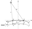
次に、演算部21の障害物方向算出部214の演算処理について、図6を用いて説明する。障害物方向算出部214は、超音波センサ1bから見た障害物4の方向を算出する。なお、超音波センサ1bから見た障害物4の方向とは、時間t2における超音波センサ1aの位置および超音波センサ1bの位置を通過する軸B1(x軸に平行)を基準として、時間t2における超音波センサ1bに対する障害物4の角度θ2[°]を示す。まず、障害物方向算出部214は、時間t2における超音波センサ1bの位置と時間t1における超音波センサ1aの位置とを結ぶ直線A1と、時間t2における超音波センサ1bの位置と障害物4の位置とを結ぶ直線A2とのなす角度θ3[°]を算出する。障害物方向算出部214は、超音波センサ1aが測定した距離D1と、超音波センサ1bが測定した距離D2と、センサ間隔算出部212が算出したセンサ間隔P2とを用いて、角度θ3を算出する(図6および下記式(6)(7)参照)。


ここで、図6に示すように、角度θ3は、移動角度θ1と角度θ2との和となる。したがって、障害物方向算出部214は、上記式(6)(7)によって算出した角度θ3から、移動角度θ1を減算することで、角度θ2を算出する(図6および下記式(8)参照)。

障害物方向算出部214が角度θ2を算出することによって、時間t2における超音波センサ1bに対する障害物4の位置(距離D2,角度θ2)が特定される。すなわち、障害物方向算出部214は、第1の距離情報および、第2の距離情報および、センサ間隔P2[mm]および、移動角度θ1[°]に基づいて、障害物4の方向を算出する。
次に、演算部21の座標算出部215の演算処理について、図7,図8を用いて説明する。座標算出部215は、時間t2における車両3の前端(原点O1)を原点とした障害物4の位置座標を算出する。なお、障害物4の位置座標とは、原点O1に対する障害物4のx軸方向の距離Dx0[mm]と、原点O1に対する障害物4のy軸方向の距離Dy0[mm]とを示す(図8参照)。なお、障害物4がy軸に対して左側にある場合、距離Dx0は負の値で示される。
まず座標算出部215は、時間t2における超音波センサ1bに対する障害物4のx軸方向の距離Dx2[mm]を算出する。座標算出部215は、障害物方向算出部214が算出した角度θ2が90°以下である場合、下記式(9)を用いて距離Dx2を算出する(図7参照)。また、座標算出部215は、障害物方向算出部214が算出した角度θ2が90°よりも大きい場合、下記式(10)を用いて距離Dx2を算出する(図7参照)。


次に、座標算出部215は、上記式(9)または(10)によって算出した距離Dx2を用いて、x軸方向における車両3の前端(原点O1)から障害物4までの距離Dx0を算出する。座標算出部215は、障害物方向算出部214が算出した角度θ2が90°以下である場合、下記式(11)を用いて距離Dx0(Dx0≦0)を算出する(図8参照)。また、座標算出部215は、障害物方向算出部214が算出した角度θ2が90°よりも大きい場合、下記式(12)を用いて距離Dx0(Dx0>0)を算出する(図8参照)。


次に、座標算出部215は、y軸方向における車両3の前端(原点O1)から障害物4までの距離Dy0を算出する。なお、超音波センサ1a,1bが設けられるバンパー31は、前端を頂点として湾曲している。y軸方向における超音波センサ1bから車両3(バンパー31)の前端までの長さ(オフセット)はL2[mm]である。この長さL2の情報は、予め座標算出部215が保持している。座標算出部215は、上記式(9)または(10)によって算出した距離Dx2と、超音波センサ1bが測定した距離D2と、予め保持している長さL2とを用いて、距離Dy0を算出する。(図8および下記式(13)(14)参照)。


このように、演算部21の座標算出部215は、上記式(9)~(14)より、時間t2における車両3の前端(原点O1)に対する障害物4の位置座標(Dx0,Dy0)を算出する。すなわち、座標算出部215は、センサ間隔、障害物方向算出部214が算出した方向に基づいて、時間t2における障害物4の位置座標を算出する。
そして、演算部21は、座標算出部215が算出した障害物4の位置情報(位置座標(Dx0,Dy0))を、通信部23を用いて外部機器5に送信する。すなわち、通信部23は、障害物4の位置情報を外部(外部機器5)に送信する。そして、車両3に搭載された表示灯などを用いて、車両3に対する障害物4の位置がドライバーに知らされる。
このように、本実施形態では、2つの超音波センサ1a,1bが異なるタイミング(時間t1,t2)に測定した障害物4までの距離(距離D1,D2)を用いて、障害物4の位置座標(Dx0,Dy0)を算出することができる。したがって、本実施形態は、障害物4の存在有無だけでなく、車両3に対する障害物4の位置情報もドライバーに知らせることができるので、ドライバーに対してより精度の高い運転支援を行うことができる。また、本実施形態では、障害物4の位置座標の算出にステアリング情報を用いていないため、演算処理が簡易化される。
また、従来の車両用障害物検知システムに用いられているデュアルソナーは、2つのマイクロフォンを一体に有しているため、2つのマイクロフォンの間隔が短く、検知距離(障害物4を検知することが可能な距離)が短くなるという問題があった。しかし、本実施形態では、超音波センサ1aが1つのマイクロフォン11aを有し、超音波センサ1bが1つのマイクロフォン11bを有しており、超音波センサ1a,1bの各々がシングルソナーで構成されている。そして、超音波センサ1aと超音波センサ1bとは各々独立しており、取付間隔P1を任意に設定することができるので、近距離から遠距離にわたって、車両3に対する障害物4の位置を算出することができる。さらに、本実施形態では、汎用性の高いシングルソナー(超音波センサ1a,1b)を用いているため、デュアルソナーに比べてコスト面で有利である。
また、従来の車両用障害物検知システムに用いられている、シングルソナーを1つ用いた構成では、障害物4の位置を特定できなかったため、車両3が障害物に接触する可能性がない領域に存在する障害物4を検知した場合にも報知が行われていた。すなわち、車両3が進入する可能性がない領域に存在する障害物4を検知した場合にも報知が行われていた。そのため、従来では、超音波センサを設ける位置や角度を調整したり、検知範囲を物理的に制限するマスク処理を行う必要があった。
しかし、本実施形態では、上述したように障害物4の位置座標を特定することができ、さらに、演算部21は、予測部216,判断部217を備える。
演算部21は、通信部23を用いて車両3のステアリング情報(操舵角)を取得する。そして、予測部216は、取得したステアリング情報から車両3の進行ルートを予測する。判断部217は、予測部216が予測した車両3の進行ルートに、座標算出部215が算出した障害物4の位置座標が含まれるか否かを判断する。判断部217は、車両3の進行ルートに障害物4の位置座標が含まれる場合、通信部23を介してブザーを鳴らしたり、警告灯を点灯させることで、車両3と障害物4とが衝突する可能性があることをドライバーに報知し、衝突回避をドライバーに促す。すなわち、通信部23は、進行ルートに障害物4の位置が含まれると判断部217で判断された場合、障害物4の位置情報を外部機器5に送信する。
一方、通信部23は、進行ルートに障害物4の位置が含まれないと判断部217で判断された場合、上記位置情報を外部に送信しない。このように、本実施形態では、車両3が障害物に接触する可能性がない領域を設定し、この領域に障害物4が存在する場合、障害物4の存在を示す報知を行わないように構成することができる。すなわち、車両3が進入する可能性がない領域に障害物4が存在する場合、上記報知を行わないようにすることができる。したがって、本実施形態は、ドライバーに対する不要な報知を防止することができると共に、従来のように超音波センサの設置に対する制限がなく、検知範囲を物理的に制限するマスク処理も必要がない。
また、本実施形態では、車両3の移動中であっても、車両3の移動距離L1を用いて(上記式(1)参照)、障害物4の位置を算出するので、車両3の移動による誤差がなく、障害物4の位置の算出精度が高い。
また、本実施形態では、超音波センサ1aの測定データと、超音波センサ1aが測定してから測定時間差C1経過後の超音波センサ1bの測定データとを用いて、演算部21が障害物4の位置を算出している。しかし、超音波センサ1aの測定データと超音波センサ1bの測定データとの時間の前後関係は、上記に限定されない。例えば、超音波センサ1bの測定データと、超音波センサ1bが測定してから測定時間差C1経過後の超音波センサ1aの測定データとを用いて、演算部21が障害物4の位置を算出してもよい。
また、超音波センサ1aまたは1bの最新の測定データと、この測定データの測定時間差C1前の超音波センサ1bまたは1aの測定データとを用いて、演算部21が障害物4の位置を算出してもよい。
すなわち、演算部21は、以下の動作を繰り返してもよい。まず、演算部21は、時間t1(第1のタイミング)における超音波センサ1aの測定データと、時間t1から測定時間差C1が経過した後の時間t2(第2のタイミング)における超音波センサ1bの測定データとを用いて、障害物4の位置を算出する。次に、演算部21は、時間t2における超音波センサ1bの測定データと、時間t2から測定時間差C1が経過した後の時間(第3のタイミング)における超音波センサ1aの測定データとを用いて、障害物4の位置を算出する。以後、演算部21は、このような動作を繰り返す。
言い換えると、演算部21は、第2のタイミング(時間t2)における位置(障害物4の位置)を算出した後に、以下の動作を行ってもよい。演算部21は、第2の距離情報と第3の距離情報とを用いて、第2のタイミングより遅い第3のタイミングにおける障害物4の位置を算出する。第3の距離情報は、第1の超音波センサ(超音波センサ1a)が、第3のタイミングに測定した第1の距離(車両3から障害物4までの距離)を示す。
このように構成することによって、測定時間差C1毎に、障害物4の位置を算出することができるので、障害物4の位置情報の更新頻度が高くなる。
なお、本実施形態では、超音波センサ1aと超音波センサ1bとが交互に障害物4までの距離を測定しているが、超音波センサ1aと超音波センサ1bとが同時に障害物4までの距離を周期的に測定するように構成してもよい。この場合、演算部21は、超音波センサ1aと超音波センサ1bとで、測定時間差C1だけ異なる時間の測定データを記憶部22から取得して演算処理することで、障害物4の位置を算出する。
すなわち、演算部21は以下の動作を行ってもよい。演算部21は、第1の距離情報および第2の距離情報を用いて第2のタイミング(時間t2)における障害物4の位置を検出する。このときに、演算部21は、第3の距離情報と第4の距離情報とを用いて、第2のタイミングにおける位置をさらに算出する。第3の距離情報は、第1の超音波センサ(超音波センサ1a)が、第2のタイミングに測定した第1の距離を示す。第4の距離情報は、第2の超音波センサ(超音波センサ1b)が、第1のタイミング(時間t1)に測定した第2の距離を示す。
また、本実施形態に係る車両用障害物検知システムは、2つの超音波センサ1a,1bを備えた構成で、2つの超音波センサ1a,1bの測定データを用いて障害物4の位置を算出しているが、さらに複数の超音波センサを備えた構成でもよい。この場合、演算部21は、複数の超音波センサのうち、いずれか2つの超音波センサの測定データを適宜組み合わせて障害物4の位置を算出する。多くの超音波センサを設けることによって、障害物4の検知範囲を広げることができる。なお、本実施形態では、車両3の前側のバンパー31に超音波センサ1a,1bを設けているが、超音波センサ1a,1bの設置位置は、この位置に限定されず、例えば車両3の後ろ側のバンパーに設けてもよい。
また、本実施形態の通信部23は、CAN通信に対応した通信インターフェースであるが、CAN通信に限定されない。例えば、通信部23は、シリアル等のアナログ通信に対応したインターフェースで構成され、外部機器5と通信を行ってよい。すなわち、通信部23は、障害物4の位置情報を、アナログ通信を用いて外部に送信してもよい。別の例として、通信部23は、CAN通信およびアナログ通信のいずれにも対応したインターフェースであってもよい。この例では、通信部23は、CAN通信およびアナログ通信のいずれかを用いて、上記位置情報を外部に送信する。
本発明をいくつかの好ましい実施形態によって記述したが、本発明の本来の精神および範囲、すなわち請求の範囲を逸脱することなく、当業者によってさまざまな修正および変形が可能である。
Claims (13)
- 車両の外面に設けられる第1のマイクロフォンを有し、前記第1のマイクロフォンが超音波を送受信することで、前記車両から障害物までの第1の距離を測定する第1の超音波センサが、第1のタイミングに測定した前記第1の距離を示す第1の距離情報と、
前記車両の外面に設けられる第2のマイクロフォンを有し、前記第2のマイクロフォンが超音波を送受信することで、前記車両から前記障害物までの第2の距離を測定する第2の超音波センサが、前記第1のタイミングより遅い第2のタイミングに測定した前記第2の距離を示す第2の距離情報とを用いて、
前記第2のタイミングにおける前記車両に対する前記障害物の位置を算出する演算部を備える
ことを特徴とする車両用障害物検知装置。 - 前記演算部は、
前記車両の移動速度に基づいて、前記第1のタイミングから前記第2のタイミングまでの間に移動した前記車両の移動距離を算出する移動距離算出部と、
前記第1の超音波センサと前記第2の超音波センサとの取付間隔および、前記移動距離算出部が算出した前記移動距離に基づいて、前記第1のタイミングにおける前記第1の超音波センサと前記第2のタイミングにおける前記第2の超音波センサとの間のセンサ間隔を算出するセンサ間隔算出部と、
前記センサ間隔算出部が算出した前記センサ間隔に基づいて、前記第1のタイミングにおける前記第1の超音波センサの位置を中心としたときの、前記第1のタイミングから前記第2のタイミングまでの間を移動した前記第2の超音波センサの移動角度を算出する移動角度算出部と、
前記第1の距離情報および、前記第2の距離情報および、前記センサ間隔算出部が算出した前記センサ間隔および、前記移動角度算出部が算出した前記移動角度に基づいて、前記第2のタイミングにおける前記第2の超音波センサに対する前記障害物の方向を算出する障害物方向算出部と
を備えることを特徴とする請求項1記載の車両用障害物検知装置。 - 前記演算部が算出した前記位置を示す位置情報を外部に送信する通信部をさらに備えることを特徴とする請求項1または2に記載の車両用障害物検知装置。
- 前記通信部は、前記位置情報を、Controller Area Network通信を用いて前記外部に送信することを特徴とする請求項3記載の車両用障害物検知装置。
- 前記通信部は、前記位置情報を、アナログ通信を用いて前記外部に送信することを特徴とする請求項3または4に記載の車両用障害物検知装置。
- 前記通信部は、前記車両に設けられた外部機器に前記位置情報を送信することを特徴とする請求項3乃至5のうちいずれか1項に記載の車両用障害物検知装置。
- 前記車両の操舵角に基づいて、前記車両の進行ルートを予測する予測部と、
前記予測部が予測した前記進行ルートに、前記演算部が算出した前記位置が含まれるか否かを判断する判断部と
を備えることを特徴とする請求項1乃至6のうちいずれか1項に記載の車両用障害物検知装置。 - 前記車両の操舵角に基づいて、前記車両の進行ルートを予測する予測部と、
前記予測部が予測した前記進行ルートに、前記演算部が算出した前記位置が含まれるか否かを判断する判断部とを備え、
前記通信部は、前記進行ルートに前記位置が含まれると前記判断部で判断された場合、前記位置情報を前記外部に送信し、前記進行ルートに前記位置が含まれないと前記判断部で判断された場合、前記位置情報を前記外部に送信しない
ことを特徴とする請求項3乃至6のうちいずれか1項に記載の車両用障害物検知装置。 - 前記センサ間隔、前記障害物方向算出部が算出した前記方向に基づいて、前記第2のタイミングにおける前記障害物の位置座標を算出する座標算出部をさらに備えることを特徴とする請求項2記載の車両用障害物検知装置。
- 前記演算部は、
前記第2のタイミングにおける前記位置を算出した後に、
前記第2の距離情報と、
前記第1の超音波センサが、前記第2のタイミングより遅い第3のタイミングに測定した前記第1の距離を示す第3の距離情報とを用いて、
前記第3のタイミングにおける前記位置を算出する
ことを特徴とする請求項1記載の車両用障害物検知装置。 - 前記第1の超音波センサは、前記第1のマイクロフォンを収納する第1のハウジングをさらに有し、
前記第2の超音波センサは、前記第2のマイクロフォンを収納する第2のハウジングをさらに有する
ことを特徴とする請求項1乃至10のうちいずれか1項に記載の車両用障害物検知装置。 - 車両に設けられることを特徴とする請求項1乃至11のうちいずれか1項に記載の車両用障害物検知装置。
- 車両の外面に設けられる第1のマイクロフォンを有し、前記第1のマイクロフォンが超音波を送受信することで、前記車両から障害物までの第1の距離を測定する第1の超音波センサと、
前記車両の外面に設けられる第2のマイクロフォンを有し、前記第2のマイクロフォンが超音波を送受信することで、前記車両から前記障害物までの第2の距離を測定する第2の超音波センサと、
前記第1の超音波センサが第1のタイミングに測定した前記第1の距離を示す第1の距離情報および、前記第2の超音波センサが前記第1のタイミングより遅い第2のタイミングに測定した前記第2の距離を示す第2の距離情報を用いて、前記第2のタイミングにおける前記車両に対する前記障害物の位置を算出する演算部と
を備えることを特徴する車両用障害物検知システム。
Priority Applications (3)
| Application Number | Priority Date | Filing Date | Title |
|---|---|---|---|
| EP14761108.1A EP2966472A4 (en) | 2013-03-04 | 2014-02-27 | VEHICLE DETECTION DEVICE AND VEHICLE DISABLING DETECTION DEVICE |
| CN201480012086.8A CN105008955B (zh) | 2013-03-04 | 2014-02-27 | 车辆障碍物检测设备和车辆障碍物检测系统 |
| US14/772,380 US9507023B2 (en) | 2013-03-04 | 2014-02-27 | Obstacle detection device for vehicle and obstacle detection system for vehicle |
Applications Claiming Priority (2)
| Application Number | Priority Date | Filing Date | Title |
|---|---|---|---|
| JP2013042058A JP6123133B2 (ja) | 2013-03-04 | 2013-03-04 | 車両用障害物検知装置および、車両用障害物検知システム |
| JP2013-042058 | 2013-03-04 |
Publications (1)
| Publication Number | Publication Date |
|---|---|
| WO2014136408A1 true WO2014136408A1 (ja) | 2014-09-12 |
Family
ID=51490946
Family Applications (1)
| Application Number | Title | Priority Date | Filing Date |
|---|---|---|---|
| PCT/JP2014/001068 Ceased WO2014136408A1 (ja) | 2013-03-04 | 2014-02-27 | 車両用障害物検知装置および、車両用障害物検知システム |
Country Status (6)
| Country | Link |
|---|---|
| US (1) | US9507023B2 (ja) |
| EP (1) | EP2966472A4 (ja) |
| JP (1) | JP6123133B2 (ja) |
| CN (1) | CN105008955B (ja) |
| TW (1) | TW201447835A (ja) |
| WO (1) | WO2014136408A1 (ja) |
Cited By (2)
| Publication number | Priority date | Publication date | Assignee | Title |
|---|---|---|---|---|
| CN104569992A (zh) * | 2014-12-02 | 2015-04-29 | 科世达(上海)管理有限公司 | 汽车浅水行驶避障方法、系统及装置 |
| CN106032135A (zh) * | 2014-11-25 | 2016-10-19 | 现代摩比斯株式会社 | 车辆后方障碍物显示方法及其装置 |
Families Citing this family (38)
| Publication number | Priority date | Publication date | Assignee | Title |
|---|---|---|---|---|
| US9518830B1 (en) | 2011-12-28 | 2016-12-13 | Intelligent Technologies International, Inc. | Vehicular navigation system updating based on object presence |
| US9751527B2 (en) * | 2014-07-09 | 2017-09-05 | Alcatel-Lucent Usa Inc. | In-the-road, passable obstruction avoidance arrangement |
| JP6404679B2 (ja) | 2014-10-22 | 2018-10-10 | 株式会社デンソー | 物体検知装置 |
| JP6442225B2 (ja) * | 2014-10-22 | 2018-12-19 | 株式会社デンソー | 物体検知装置 |
| JP6484000B2 (ja) | 2014-10-22 | 2019-03-13 | 株式会社デンソー | 物体検知装置 |
| JP2016080641A (ja) | 2014-10-22 | 2016-05-16 | 株式会社デンソー | 物体検知装置 |
| JP6462308B2 (ja) | 2014-10-22 | 2019-01-30 | 株式会社デンソー | 物体検知装置 |
| JP6430777B2 (ja) | 2014-10-22 | 2018-11-28 | 株式会社デンソー | 物体検知装置 |
| JP6292097B2 (ja) * | 2014-10-22 | 2018-03-14 | 株式会社デンソー | 側方測距センサ診断装置 |
| JP6430778B2 (ja) | 2014-10-22 | 2018-11-28 | 株式会社デンソー | 物体検知装置 |
| JP6474228B2 (ja) | 2014-10-22 | 2019-02-27 | 株式会社デンソー | 物体検知装置 |
| CN106331549A (zh) * | 2015-06-30 | 2017-01-11 | 中强光电股份有限公司 | 投影机装置 |
| US9873428B2 (en) * | 2015-10-27 | 2018-01-23 | Ford Global Technologies, Llc | Collision avoidance using auditory data |
| JP6715456B2 (ja) * | 2016-09-30 | 2020-07-01 | パナソニックIpマネジメント株式会社 | 検出装置、検出方法、および検出プログラム |
| KR101892028B1 (ko) | 2016-10-26 | 2018-08-27 | 현대자동차주식회사 | 음향 추적 정보 제공 방법, 차량용 음향 추적 장치, 및 이를 포함하는 차량 |
| KR102045286B1 (ko) * | 2016-11-16 | 2019-11-18 | 고려대학교 산학협력단 | 초음파 센서를 대상으로 하는 공격 탐지 장치 및 방법 |
| JP2018092240A (ja) * | 2016-11-30 | 2018-06-14 | 株式会社デンソー | 位置検出システム |
| DE102016224928A1 (de) * | 2016-12-14 | 2018-06-14 | Robert Bosch Gmbh | Verfahren zum Betrieb eines Ultraschallsensors |
| US11488477B2 (en) * | 2017-02-22 | 2022-11-01 | Mitsubishi Electric Corporation | Driving assistance device, map transmission device, driving assistance program, map transmission program, and driving assistance system |
| US10473759B2 (en) * | 2017-03-28 | 2019-11-12 | GM Global Technology Operations LLC | Tool for automatic multiple radar calibration |
| CN107229054A (zh) * | 2017-06-22 | 2017-10-03 | 深圳传音通讯有限公司 | 预警方法、装置及终端设备 |
| CN109426267A (zh) * | 2017-08-30 | 2019-03-05 | 苏州宝时得电动工具有限公司 | 自移动设备 |
| JP6945399B2 (ja) * | 2017-09-13 | 2021-10-06 | 株式会社クボタ | 障害物検出装置 |
| CN108226910B (zh) * | 2018-01-19 | 2021-10-29 | 常州市鼎兴电子有限公司 | 单体超声传感器探测系统 |
| CN109229015B (zh) * | 2018-02-11 | 2021-08-03 | 辅易航智能科技(苏州)有限公司 | 基于超声波传感器实现车辆360度障碍物报警提示的方法 |
| JPWO2019160102A1 (ja) * | 2018-02-15 | 2021-02-04 | パナソニックIpマネジメント株式会社 | 測定装置、測定方法、測定プログラム、測定プログラムを記録した記録媒体および車両制御装置 |
| CN109472973B (zh) * | 2018-03-19 | 2021-01-19 | 国网浙江桐乡市供电有限公司 | 一种基于声音辨识的实时交通展示方法 |
| CN109050391B (zh) * | 2018-07-26 | 2020-06-05 | 北京经纬恒润科技有限公司 | 一种远光灯控制方法及装置 |
| CN111289947B (zh) * | 2018-12-07 | 2023-04-07 | 阿里巴巴集团控股有限公司 | 信息处理方法、装置以及设备 |
| DE102019103792A1 (de) | 2019-02-14 | 2020-08-20 | Brose Fahrzeugteile Se & Co. Kommanditgesellschaft, Bamberg | Verstellbaugruppe für ein Fahrzeug mit Ultraschallsystem und Verfahren zur Hindernisdetektion |
| JP7107274B2 (ja) * | 2019-04-23 | 2022-07-27 | 株式会社豊田自動織機 | 障害物検出装置及び障害物検出方法 |
| CN112055119B (zh) * | 2019-06-06 | 2021-08-17 | 北京小米移动软件有限公司 | 识别障碍物的终端、方法、装置及存储介质 |
| CN112346445A (zh) * | 2019-08-07 | 2021-02-09 | 坎德拉(深圳)科技创新有限公司 | 一种配送机器人及其避障方法、计算机存储介质 |
| TWI728470B (zh) * | 2019-09-18 | 2021-05-21 | 財團法人車輛研究測試中心 | 目標物意圖預測方法及其系統 |
| CN112606973B (zh) * | 2020-12-29 | 2023-03-28 | 武汉理工大学 | 一种水空两栖立体式搜救系统及方法 |
| CN114578363B (zh) * | 2022-03-04 | 2023-10-13 | 苏州优达斯汽车科技有限公司 | 一种超声波检测系统和方法 |
| CN117048594A (zh) * | 2022-05-06 | 2023-11-14 | 上海汽车集团股份有限公司 | 一种泊车车位边界的确定方法及装置 |
| CN115356733A (zh) * | 2022-07-26 | 2022-11-18 | 润光智能(深圳)有限公司 | 基于多雷达的障碍物定位方法、装置、设备及存储介质 |
Citations (5)
| Publication number | Priority date | Publication date | Assignee | Title |
|---|---|---|---|---|
| JP2006216066A (ja) | 2006-02-13 | 2006-08-17 | Matsushita Electric Works Ltd | 車両用障害物検知装置 |
| JP2007192763A (ja) * | 2006-01-23 | 2007-08-02 | Matsushita Electric Ind Co Ltd | 自律走行装置 |
| JP2008225583A (ja) * | 2007-03-08 | 2008-09-25 | Toyota Motor Corp | 周囲環境推定装置及び周囲環境推定システム |
| JP2010197931A (ja) * | 2009-02-27 | 2010-09-09 | Seiko Epson Corp | 液晶表示装置 |
| JP2011220860A (ja) * | 2010-04-09 | 2011-11-04 | Toyota Motor Corp | 障害物検出装置 |
Family Cites Families (22)
| Publication number | Priority date | Publication date | Assignee | Title |
|---|---|---|---|---|
| JPS60249075A (ja) * | 1984-05-25 | 1985-12-09 | Casio Comput Co Ltd | 障害物位置検出装置 |
| DE3879923D1 (de) * | 1988-01-30 | 1993-05-06 | Mayser Gmbh & Co | Verfahren zum orten eines hindernisses. |
| DE4023538A1 (de) * | 1990-07-25 | 1992-01-30 | Bosch Gmbh Robert | Kollisionswarneinrichtung |
| JPH06317662A (ja) * | 1993-05-10 | 1994-11-15 | Fujitsu General Ltd | 超音波装置 |
| SE515621C2 (sv) * | 1995-05-08 | 2001-09-10 | Ericsson Telefon Ab L M | Förfarande vid lägesbestämning |
| US5872536A (en) * | 1997-02-19 | 1999-02-16 | Hittite Microwave Corporation | Multi-sensor anticipatory object detection system |
| DE19711467C2 (de) * | 1997-03-20 | 2000-12-07 | Mannesmann Vdo Ag | Verfahren zur Bestimmung des senkrechten Abstandes zwischen einem Objekt und einer sich örtlich verändernden Einrichtung |
| DE19842250A1 (de) * | 1998-09-15 | 2000-03-16 | Mannesmann Vdo Ag | Verfahren zur Bestimmung des Abstandes zwischen einem Objekt und einer sich örtlich verändernden Einrichtung, insbesondere einem Kraftfahrzeug |
| JP2002162461A (ja) * | 2000-11-28 | 2002-06-07 | Nissan Motor Co Ltd | 周囲検出装置 |
| US6522288B1 (en) * | 2002-01-09 | 2003-02-18 | M/A-Com, Inc. | Method and apparatus for determining location of objects based on range readings from multiple sensors |
| US6628227B1 (en) * | 2002-07-23 | 2003-09-30 | Ford Global Technologies, Llc | Method and apparatus for determining a target vehicle position from a source vehicle using a radar |
| DE10341128A1 (de) * | 2003-09-06 | 2005-03-31 | Daimlerchrysler Ag | Vorrichtung und Verfahren zur Erfassung eines momentanen Abstandes eines Kraftfahrzeugs von einem Hindernis |
| DE10343175A1 (de) * | 2003-09-18 | 2005-04-14 | Robert Bosch Gmbh | Verfahren zur Abstandsmessung und Messeinrichtung hierzu |
| DE10361315A1 (de) * | 2003-12-19 | 2005-07-21 | Valeo Schalter Und Sensoren Gmbh | Verfahren und Vorrichtung zum Bestimmen der Position von mindestens einem Reflexionspunkt auf einem Hindernis |
| JP2007112297A (ja) * | 2005-10-20 | 2007-05-10 | Denso Corp | 車両用障害物衝突回避システム |
| CN101303410B (zh) * | 2007-05-08 | 2011-08-24 | 李世雄 | 单方发射暨多方接收的障碍物检测方法及其装置 |
| US20090254260A1 (en) * | 2008-04-07 | 2009-10-08 | Axel Nix | Full speed range adaptive cruise control system |
| US8217773B2 (en) * | 2008-12-04 | 2012-07-10 | Denso Corporation | Field watch apparatus |
| JP5071743B2 (ja) * | 2010-01-19 | 2012-11-14 | アイシン精機株式会社 | 車両周辺監視装置 |
| DE102010045657A1 (de) * | 2010-09-17 | 2012-03-22 | Wabco Gmbh | Umfeld-Überwachungssystem für ein Fahrzeug |
| WO2012140769A1 (ja) * | 2011-04-14 | 2012-10-18 | トヨタ自動車株式会社 | 車両用物体検出装置および方法 |
| CN202471965U (zh) * | 2011-12-02 | 2012-10-03 | 中国计量学院 | 一种可探测障碍物位置的导盲装置 |
-
2013
- 2013-03-04 JP JP2013042058A patent/JP6123133B2/ja active Active
-
2014
- 2014-02-27 EP EP14761108.1A patent/EP2966472A4/en not_active Withdrawn
- 2014-02-27 WO PCT/JP2014/001068 patent/WO2014136408A1/ja not_active Ceased
- 2014-02-27 CN CN201480012086.8A patent/CN105008955B/zh not_active Expired - Fee Related
- 2014-02-27 US US14/772,380 patent/US9507023B2/en not_active Expired - Fee Related
- 2014-03-03 TW TW103107049A patent/TW201447835A/zh unknown
Patent Citations (5)
| Publication number | Priority date | Publication date | Assignee | Title |
|---|---|---|---|---|
| JP2007192763A (ja) * | 2006-01-23 | 2007-08-02 | Matsushita Electric Ind Co Ltd | 自律走行装置 |
| JP2006216066A (ja) | 2006-02-13 | 2006-08-17 | Matsushita Electric Works Ltd | 車両用障害物検知装置 |
| JP2008225583A (ja) * | 2007-03-08 | 2008-09-25 | Toyota Motor Corp | 周囲環境推定装置及び周囲環境推定システム |
| JP2010197931A (ja) * | 2009-02-27 | 2010-09-09 | Seiko Epson Corp | 液晶表示装置 |
| JP2011220860A (ja) * | 2010-04-09 | 2011-11-04 | Toyota Motor Corp | 障害物検出装置 |
Non-Patent Citations (1)
| Title |
|---|
| See also references of EP2966472A4 |
Cited By (3)
| Publication number | Priority date | Publication date | Assignee | Title |
|---|---|---|---|---|
| CN106032135A (zh) * | 2014-11-25 | 2016-10-19 | 现代摩比斯株式会社 | 车辆后方障碍物显示方法及其装置 |
| CN106032135B (zh) * | 2014-11-25 | 2018-12-14 | 现代摩比斯株式会社 | 车辆后方障碍物显示方法及其装置 |
| CN104569992A (zh) * | 2014-12-02 | 2015-04-29 | 科世达(上海)管理有限公司 | 汽车浅水行驶避障方法、系统及装置 |
Also Published As
| Publication number | Publication date |
|---|---|
| EP2966472A1 (en) | 2016-01-13 |
| US9507023B2 (en) | 2016-11-29 |
| EP2966472A4 (en) | 2016-04-20 |
| US20160003943A1 (en) | 2016-01-07 |
| CN105008955A (zh) | 2015-10-28 |
| JP6123133B2 (ja) | 2017-05-10 |
| TW201447835A (zh) | 2014-12-16 |
| JP2014169927A (ja) | 2014-09-18 |
| CN105008955B (zh) | 2017-02-22 |
Similar Documents
| Publication | Publication Date | Title |
|---|---|---|
| JP6123133B2 (ja) | 車両用障害物検知装置および、車両用障害物検知システム | |
| JP6404679B2 (ja) | 物体検知装置 | |
| US10006999B2 (en) | Driver assistance system for detecting an object in the surroundings of a vehicle | |
| RU2503027C2 (ru) | Система помощи водителю транспортного средства и способ управления ее работой | |
| JP6333412B2 (ja) | 障害物検知装置 | |
| CN105539437B (zh) | 对象检测装置 | |
| JP6474228B2 (ja) | 物体検知装置 | |
| US9953532B2 (en) | Obstacle warning apparatus | |
| CN105549021B (zh) | 对象检测装置 | |
| US10192443B2 (en) | Collision avoidance system and collision avoidance method | |
| CN113167890A (zh) | 物体检测装置以及物体检测方法 | |
| JP2016080643A (ja) | 物体検知装置 | |
| US20180100921A1 (en) | Ultrasonic sensor device and sensing method of ultrasonic sensor device | |
| JP2015172581A (ja) | 距離決定の装置と方法 | |
| US11579277B2 (en) | Position detection system and processing device | |
| WO2016063533A1 (ja) | 車載用物体判別装置 | |
| US20240210561A1 (en) | Object detection system and object detection device | |
| JP4730832B2 (ja) | 車載レーダ装置 | |
| JP2022149205A (ja) | 物体検出装置、車両及び物体検出方法 | |
| JP2021135277A (ja) | 統合情報生成装置および測定システム | |
| KR20160031736A (ko) | 무선 식별 신호를 이용한 자동차의 충돌 방지 장치 및 방법 | |
| JPWO2019160102A1 (ja) | 測定装置、測定方法、測定プログラム、測定プログラムを記録した記録媒体および車両制御装置 |
Legal Events
| Date | Code | Title | Description |
|---|---|---|---|
| 121 | Ep: the epo has been informed by wipo that ep was designated in this application |
Ref document number: 14761108 Country of ref document: EP Kind code of ref document: A1 |
|
| WWE | Wipo information: entry into national phase |
Ref document number: 14772380 Country of ref document: US |
|
| NENP | Non-entry into the national phase |
Ref country code: DE |
|
| WWE | Wipo information: entry into national phase |
Ref document number: 2014761108 Country of ref document: EP |