WO2014136423A1 - Dispositif de climatisation de véhicule et son unité de composant - Google Patents
Dispositif de climatisation de véhicule et son unité de composant Download PDFInfo
- Publication number
- WO2014136423A1 WO2014136423A1 PCT/JP2014/001131 JP2014001131W WO2014136423A1 WO 2014136423 A1 WO2014136423 A1 WO 2014136423A1 JP 2014001131 W JP2014001131 W JP 2014001131W WO 2014136423 A1 WO2014136423 A1 WO 2014136423A1
- Authority
- WO
- WIPO (PCT)
- Prior art keywords
- refrigerant
- heat exchanger
- water
- coolant
- heat
- Prior art date
- Legal status (The legal status is an assumption and is not a legal conclusion. Google has not performed a legal analysis and makes no representation as to the accuracy of the status listed.)
- Ceased
Links
Images


Classifications
-
- B—PERFORMING OPERATIONS; TRANSPORTING
- B60—VEHICLES IN GENERAL
- B60H—ARRANGEMENTS OF HEATING, COOLING, VENTILATING OR OTHER AIR-TREATING DEVICES SPECIALLY ADAPTED FOR PASSENGER OR GOODS SPACES OF VEHICLES
- B60H1/00—Heating, cooling or ventilating devices
- B60H1/00007—Combined heating, ventilating, or cooling devices
-
- B—PERFORMING OPERATIONS; TRANSPORTING
- B60—VEHICLES IN GENERAL
- B60H—ARRANGEMENTS OF HEATING, COOLING, VENTILATING OR OTHER AIR-TREATING DEVICES SPECIALLY ADAPTED FOR PASSENGER OR GOODS SPACES OF VEHICLES
- B60H1/00—Heating, cooling or ventilating devices
- B60H1/00642—Control systems or circuits; Control members or indication devices for heating, cooling or ventilating devices
- B60H1/00814—Control systems or circuits characterised by their output, for controlling particular components of the heating, cooling or ventilating installation
- B60H1/00878—Control systems or circuits characterised by their output, for controlling particular components of the heating, cooling or ventilating installation the components being temperature regulating devices
- B60H1/00899—Controlling the flow of liquid in a heat pump system
- B60H1/00921—Controlling the flow of liquid in a heat pump system where the flow direction of the refrigerant does not change and there is an extra subcondenser, e.g. in an air duct
-
- B—PERFORMING OPERATIONS; TRANSPORTING
- B60—VEHICLES IN GENERAL
- B60H—ARRANGEMENTS OF HEATING, COOLING, VENTILATING OR OTHER AIR-TREATING DEVICES SPECIALLY ADAPTED FOR PASSENGER OR GOODS SPACES OF VEHICLES
- B60H1/00—Heating, cooling or ventilating devices
- B60H1/32—Cooling devices
- B60H1/3204—Cooling devices using compression
- B60H1/3228—Cooling devices using compression characterised by refrigerant circuit configurations
- B60H1/32284—Cooling devices using compression characterised by refrigerant circuit configurations comprising two or more secondary circuits, e.g. at evaporator and condenser side
-
- B—PERFORMING OPERATIONS; TRANSPORTING
- B60—VEHICLES IN GENERAL
- B60H—ARRANGEMENTS OF HEATING, COOLING, VENTILATING OR OTHER AIR-TREATING DEVICES SPECIALLY ADAPTED FOR PASSENGER OR GOODS SPACES OF VEHICLES
- B60H1/00—Heating, cooling or ventilating devices
- B60H1/00642—Control systems or circuits; Control members or indication devices for heating, cooling or ventilating devices
- B60H1/00814—Control systems or circuits characterised by their output, for controlling particular components of the heating, cooling or ventilating installation
- B60H1/00878—Control systems or circuits characterised by their output, for controlling particular components of the heating, cooling or ventilating installation the components being temperature regulating devices
- B60H2001/00928—Control systems or circuits characterised by their output, for controlling particular components of the heating, cooling or ventilating installation the components being temperature regulating devices comprising a secondary circuit
-
- B—PERFORMING OPERATIONS; TRANSPORTING
- B60—VEHICLES IN GENERAL
- B60H—ARRANGEMENTS OF HEATING, COOLING, VENTILATING OR OTHER AIR-TREATING DEVICES SPECIALLY ADAPTED FOR PASSENGER OR GOODS SPACES OF VEHICLES
- B60H1/00—Heating, cooling or ventilating devices
- B60H1/00642—Control systems or circuits; Control members or indication devices for heating, cooling or ventilating devices
- B60H1/00814—Control systems or circuits characterised by their output, for controlling particular components of the heating, cooling or ventilating installation
- B60H1/00878—Control systems or circuits characterised by their output, for controlling particular components of the heating, cooling or ventilating installation the components being temperature regulating devices
- B60H2001/00949—Control systems or circuits characterised by their output, for controlling particular components of the heating, cooling or ventilating installation the components being temperature regulating devices comprising additional heating/cooling sources, e.g. second evaporator
Definitions
- the present invention relates to a vehicle air conditioner and a component unit of the vehicle air conditioner.
- Patent Document 1 a vehicle air conditioner that uses a heat pump to cool and heat the passenger compartment has been proposed (see, for example, Patent Document 1).
- the conventional vehicle air conditioner that heats the vehicle interior using the heat of the engine coolant has a problem that the vehicle interior cannot be heated when the water temperature of the engine coolant is not high.
- Such a problem also applies to a case in which exhaust heat is obtained from a heat generating component other than the engine, such as a secondary battery that supplies electric power for traveling or an electric motor for traveling, in an electric vehicle and used for heating. To occur.
- a heat generating component other than the engine such as a secondary battery that supplies electric power for traveling or an electric motor for traveling, in an electric vehicle and used for heating.
- An object of the present invention is to provide a vehicle air conditioner capable of heating a passenger compartment with high efficiency even when the outside air temperature is low and a large amount of exhaust heat cannot be obtained from the heat generating parts of the vehicle.
- a vehicle air conditioner includes a first water refrigerant heat exchanger that exchanges heat between a low-temperature and low-pressure refrigerant in a heat pump and a coolant of a heat generating component of the vehicle to vaporize the refrigerant,
- a second water refrigerant heat exchanger that exchanges heat between the high-temperature and high-pressure refrigerant in the heat pump and the coolant for heat transport to condense the refrigerant, and the second water refrigerant heat exchanger includes a vehicle A heater core that applies heat to the air sent to the room and a coolant are connected to be able to circulate, and the first water-refrigerant heat exchanger is not connected to the heater core, and the cooling passage for the heat-generating component and the coolant The structure is connected so that it can be circulated.
- the structural unit of the vehicle air conditioner includes a first water refrigerant heat exchanger that exchanges heat between a low-temperature and low-pressure refrigerant and a coolant in the heat pump to vaporize the refrigerant, and the heat pump.
- a second water refrigerant heat exchanger that condenses the refrigerant by exchanging heat between the high-temperature and high-pressure refrigerant and the coolant; and the first water refrigerant heat exchanger and the second water refrigerant heat exchanger are accommodated.
- a housing to be integrated; a first introduction pipe for guiding an inlet of the coolant of the first water refrigerant heat exchanger to the outside of the housing; and an outlet of the coolant of the first water refrigerant heat exchanger.
- a first lead-out pipe that leads to the outside of the body, a second introduction pipe that leads the coolant inlet of the second water refrigerant heat exchanger to the outside of the housing, and a coolant of the second water refrigerant heat exchanger
- a second outlet pipe that guides the outlet to the outside of the housing is employed.
- the vehicle interior can be heated with high efficiency.
- the block diagram which shows the vehicle air conditioner of embodiment of this invention The figure explaining operation of the heating mode at the time of engine coolant medium temperature
- the figure explaining operation of dehumidification mode at the time of engine coolant middle temperature The figure explaining operation of heating mode at the time of high temperature of engine coolant
- the figure explaining the heating efficiency of this Embodiment (A) and conventional example (B) at the time of medium temperature of engine coolant The figure explaining the heating efficiency of this Embodiment (A) and the comparative example (B) at the time of engine coolant medium temperature
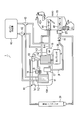
- FIG. 1 is a configuration diagram showing a vehicle air conditioner according to an embodiment of the present invention.
- a vehicle air conditioner 1 is a device that is mounted on a vehicle having an engine (internal combustion engine) and performs heating, dehumidification, and cooling of the vehicle interior.
- the vehicle air conditioner 1 includes a component unit 10, a compressor (compressor) 38, an engine cooling unit 40, three-way valves 42 and 43, a heater core 44, an evaporator 48, an expansion valve 37, an outdoor capacitor 39, and a check valve. 15, and a coolant pipe and a refrigerant pipe connecting between them.
- the heater core 44 and the evaporator 48 are disposed in an intake passage of an HVAC (Heating, Ventilation, and Air Conditioning) 70.
- the HVAC 70 is provided with a fan F1 through which intake air flows.
- the compressor 38 is driven by engine power or electricity to compress the sucked refrigerant into a high temperature and high pressure and discharge it.
- the compressed refrigerant is sent to the constituent unit 10.
- the engine cooling unit 40 includes a water jacket for flowing a coolant around the engine and a pump for flowing the coolant to the water jacket, and releases heat from the engine to the coolant flowing in the water jacket.
- the pump is rotated by the power of the engine, for example.
- the engine cooling unit 40 may include a radiator that releases heat to the outside air when the amount of exhaust heat of the engine increases.
- the heater core 44 is a device that exchanges heat between the coolant and air, and is disposed in the intake passage of the HVAC 70 that supplies air into the passenger compartment.
- the heater core 44 is supplied with a heated coolant and releases heat to the intake air that is sent into the passenger compartment during the heating operation.
- the three-way valves 42 and 43 are valves for switching whether the coolant passage of the engine cooling unit 40 is connected to the component unit 10 side or the heater core 44 side.
- the means for performing this switching is not limited to a three-way valve, and for example, a plurality of valves may be combined.
- the three-way valves 42 and 43 can perform the above switching by, for example, electrical control.
- the evaporator 48 is a device that exchanges heat between the low-temperature and low-pressure refrigerant and the air, and is disposed in the intake passage of the HVAC 70.
- the evaporator 48 is supplied with a low-temperature and low-pressure refrigerant during the cooling operation or the dehumidifying operation, and cools the intake air supplied into the passenger compartment.
- the expansion valve 37 expands the high-pressure refrigerant to a low temperature and low pressure and discharges it to the evaporator 48.
- the expansion valve 37 is disposed in the vicinity of the evaporator 48.
- the outdoor condenser 39 has a passage through which the refrigerant flows and a passage through which the air flows.
- the outdoor condenser 39 is disposed near the top of the vehicle in the engine room and exchanges heat between the refrigerant and the outside air.
- a high-temperature and high-pressure refrigerant is passed through the outdoor condenser 39 in the cooling mode and the dehumidifying mode, and heat is discharged from the refrigerant to the outside air. Outside air is blown onto the outdoor condenser 39 by, for example, a fan.
- the component unit 10 is integrally formed by being covered with a housing 10A.
- the constituent unit 10 includes a first water refrigerant heat exchanger 11, a second water refrigerant heat exchanger 12, an on-off valve 13, an expansion valve 14 with a solenoid valve, a water pump 16, and an accumulator 17. .
- the first water refrigerant heat exchanger 11 has a passage through which a low-temperature and low-pressure refrigerant flows and a passage through which a coolant flows, and performs heat exchange between the refrigerant and the coolant.
- the first water refrigerant heat exchanger 11 is supplied with a low-temperature and low-pressure refrigerant in a predetermined operation mode, and a coolant is circulated between the engine coolant 40 and the coolant. Transfers heat to low-temperature and low-pressure refrigerant.
- the second water refrigerant heat exchanger 12 has a passage through which a high-temperature and high-pressure refrigerant flows and a passage through which a cooling liquid flows, and performs heat exchange between the refrigerant and the cooling liquid.
- a coolant is circulated between the heater core 44 and the heat from the high-temperature and high-pressure refrigerant to the coolant in a predetermined operation mode.
- Two pipes h1 and h2 respectively connected to the inlet and outlet of the coolant of the first water refrigerant heat exchanger 11 are directly extended to the outside of the housing 10A and connected to the three-way valves 42 and 43. ing.
- a water pump 16 is provided on one of the two pipes h3 and h4 connected to the coolant inlet and the outlet of the second water refrigerant heat exchanger 12, respectively.
- These two pipes h3 and h4 extend to the outside of the housing 10A and are connected to the heater core 44. Further, in the middle of these two pipes h3 and h4, pipes extending from the engine cooling section 40 via the three-way valves 42 and 43 are joined and connected.
- the water pump 16 is a pump capable of circulating the coolant between the second water refrigerant heat exchanger 12 and the heater core 44 by, for example, electrical driving.
- the refrigerant pipe j1 connected to the refrigerant inlet of the second water refrigerant heat exchanger 12 extends to the outside of the housing 10A and is connected to the discharge port of the compressor 38.
- the refrigerant pipe j2 connected to the refrigerant outlet of the second water refrigerant heat exchanger 12 is branched into two inside the housing 10A.
- One of the branched refrigerant pipes extends to the outside of the housing 10 ⁇ / b> A via the on-off valve 13.
- the other of the branched refrigerant pipes j3 is connected to the refrigerant inlet of the first water refrigerant heat exchanger 11 via an expansion valve 14 with a solenoid valve.
- the refrigerant pipe j4 connected to the refrigerant outlet of the first water refrigerant heat exchanger 11 is extended to the outside of the housing 10A via the accumulator 17 and connected to the refrigerant inlet of the compressor 38.
- the refrigerant pipe of the evaporator 48 is also joined to the refrigerant suction port of the compressor 38.
- the on-off valve 13 is a valve that switches between opening and closing of the refrigerant pipe, for example, by electrical control.
- the expansion valve 14 with a solenoid valve is a valve that functions as an expansion valve when the refrigerant pipe is opened and closed, for example, by electrical control.
- the accumulator 17 separates the vaporized refrigerant that has passed through the first water refrigerant heat exchanger 11 and the non-vaporized refrigerant, and sends only the vaporized refrigerant to the compressor 38.
- the check valve 15 is provided between the compressor 38 and the evaporator 48, and is a valve that prevents the refrigerant from flowing back in the operation mode in which the refrigerant does not flow through the outdoor condenser 39 and the evaporator 48.
- This check valve 15 has the following effects. For example, consider an operation mode in which the on-off valve 13 is closed and the refrigerant flows through the refrigerant circuit passing through the first water refrigerant heat exchanger 11 and the second water refrigerant heat exchanger 12. In this operation mode, since the on-off valve 13 is closed, the refrigerant circuit passing through the outdoor condenser 39 and the evaporator 48 is shut off. However, even in this case, if the outside air is low, the refrigerant may stagnate in the outdoor condenser 39 exposed to the outside air, and the refrigerant pressure in the outdoor condenser 39 and the evaporator 48 may be low.
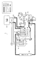
- FIG. 2 is a diagram for explaining the operation in the heating mode when the engine coolant is at a medium temperature.
- the on-off valve 13 is closed, the expansion valve 14 with a solenoid valve is opened, and the water pump 16 Is turned on, and the passages of the three-way valves 42 and 43 are switched to the first water refrigerant heat exchanger 11 side.
- a medium temperature for example, less than 60 ° C.
- the compressor 38 when the compressor 38 is operated, the refrigerant passes through the second water refrigerant heat exchanger 12, the expansion valve 14 with a solenoid valve, the first water refrigerant heat exchanger 11, the accumulator 17, and the compressor 38 in this order. It flows cyclically.
- the high-temperature and high-pressure refrigerant compressed by the compressor 38 releases heat to the coolant in the second water refrigerant heat exchanger 12 and condenses. Further, the low-temperature and low-pressure refrigerant expanded by the expansion valve 14 with a solenoid valve is vaporized by absorbing heat from the coolant in the first water refrigerant heat exchanger 11.
- Coolant flows in two paths and flows independently.
- the coolant in the first path flows cyclically between the engine cooling unit 40 and the first water refrigerant heat exchanger 11.
- the coolant in the first path cools the engine in the engine cooling unit 40 and releases heat to the low-temperature and low-pressure refrigerant in the first water-refrigerant heat exchanger 11.
- the coolant in the second path flows cyclically between the second water refrigerant heat exchanger 12 and the heater core 44 by the water pump 16.
- the coolant in the second path absorbs heat from the high-temperature and high-pressure refrigerant in the second water-refrigerant heat exchanger 12 and releases heat to the intake air that is sent into the passenger compartment in the heater core 44.
- FIG. 3 is a diagram for explaining the operation in the dehumidifying mode when the engine coolant is at a medium temperature.
- the on-off valve 13 When the operation of the dehumidifying mode is requested when the engine coolant is at a medium temperature (for example, less than 60 ° C.), the on-off valve 13 is switched to open from the state of the heating mode at the medium temperature in FIG.
- the compressor 38, the second water refrigerant heat exchanger 12, the outdoor condenser 39, the expansion valve 37, and the evaporator 48 are A refrigerant flow circulating in this order is generated.
- the low-temperature and low-pressure refrigerant flows through the evaporator 48 by this refrigerant flow, and the intake air sent into the passenger compartment can be dehumidified.
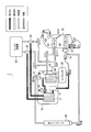
- FIG. 4 is a diagram for explaining the operation in the heating mode when the engine coolant is at a high temperature.
- the on-off valve 13 is opened, the expansion valve 14 with a solenoid valve is closed, and the water pump 16 Is turned off, and the passages of the three-way valves 42 and 43 are switched to the heater core 44 side.
- the high-temperature coolant can flow through the heater core 44 to warm the intake air sent to the passenger compartment.
- the compressor 38 is operated, so that the refrigerant passes through the second water refrigerant heat exchanger 12, the outdoor condenser 39, the expansion valve 37, the evaporator 48, and the compressor 38 in this order. Flows cyclically.
- the high-temperature and high-pressure refrigerant compressed by the compressor 38 passes through the second water refrigerant heat exchanger 12 in which the coolant does not flow almost without heat exchange, and is condensed by releasing heat to the outdoor air in the outdoor condenser 39.
- the low-temperature and low-pressure refrigerant expanded by the expansion valve 37 absorbs heat from the intake air sent into the passenger compartment by the evaporator 48 and vaporizes. Thereby, dehumidification of intake air can be performed.
- the door of the heater core 44 is closed with the refrigerant and the coolant flowing in FIG.
- the intake air passing through the HVAC 70 is cooled by the evaporator 48, and is sent directly to the vehicle interior without passing through the heater core 44, thereby cooling the vehicle interior.
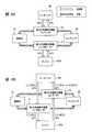
- FIG. 5 is a diagram for explaining the heating efficiency between the present embodiment (A) and the conventional example (B) when the engine coolant is at a medium temperature.
- FIG. 5 an example of the stable temperature of the coolant flowing in each part is shown beside the arrow indicating the flow of the coolant.
- the heating mode (A) at the middle temperature of the present embodiment and the conventional Comparison with the heating mode (B) in the example is performed.
- 5B is a configuration having a heat pump system including a compressor 51, a water-refrigerant heat exchanger 52 that functions as a condenser, an expansion valve 53, and an outdoor heat exchanger 54 that functions as an evaporator.
- the engine coolant is heated by the water-refrigerant heat exchanger 52 and sent to the heater core 44.
- This configuration corresponds to the configuration of FIG.
- the medium temperature coolant is supplied to the first water refrigerant heat exchanger 11 that functions as an evaporator.
- the heat pump system operates efficiently, and a large amount of heat can be transferred from the first water refrigerant heat exchanger 11 to the second water refrigerant heat exchanger 12 with low power consumption. Therefore, the second water refrigerant heat exchanger 12 is maintained at a high temperature, and the vehicle interior can be sufficiently warmed by supplying a high-temperature coolant to the heater core 44.
- the amount of the coolant flowing through the heater core 44 depends on the rotational speed of the coolant pump of the engine 40A.
- the flow rate of the coolant in the heater core 44 can be controlled independently of the flow rate of the coolant in the engine 40A. Therefore, in the present embodiment, even when the engine 40A is stopped due to idling stop or the like, it is possible to maintain the heating capacity of the passenger compartment by flowing the coolant through the heater core 44.
- FIG. 6 is a diagram for explaining the heating efficiency of the present embodiment (A) and the comparative example (B) when the engine coolant is at a medium temperature.
- FIG. 6 an example of a stable temperature of the coolant flowing through each part is shown alongside the arrow indicating the flow of the coolant.
- FIG. 6B the unstable temperature of the coolant is shown in parentheses.
- the comparative example of FIG. 6B has the same heat pump system as that of the present embodiment, while the coolant is used as the heater core 44, the first water refrigerant heat exchanger 11, the cooling passage of the engine 40A, the second water refrigerant heat.
- the configuration is such that it flows through the exchanger 12 in this order.
- the compressor 38 is driven in the same manner as in the present embodiment, and the heater core 44 is heated to a high temperature (for example, an unstable temperature (1) 70 ° C.) as in the present embodiment. It is assumed that the cooling liquid is supplied.
- a high temperature for example, an unstable temperature (1) 70 ° C.
- the coolant that has passed through the heater core 44 is sent to the first water-refrigerant heat exchanger 11. Therefore, in the case of the above assumption, the temperature of the coolant input to the first water-refrigerant heat exchanger 11 is higher than that in the present embodiment (for example, an unstable temperature (1) 50 ° C.). As a result, the temperature of the coolant that passes through the first water-refrigerant heat exchanger 11 and is sent to the engine 40A also becomes higher than that in the present embodiment (for example, an unstable temperature (1) 25 ° C.).
- the temperature difference between the coolant sent from the first water-refrigerant heat exchanger 11 and the engine 40A becomes small, so that the heat radiation from the engine 40A to the coolant is small.
- the coolant of the engine 40A is sent to the second water refrigerant heat exchanger 12.
- the temperature of the coolant input to the second water refrigerant heat exchanger 12 is lower than that of the present embodiment (for example, an unstable temperature (1) 40 ° C.).
- the temperature of the coolant output from the second water refrigerant heat exchanger 12 cannot be maintained, and the temperature becomes low (for example, an unstable temperature (2) 65 ° C.).
- the stable temperature of the coolant in each part of the comparative example of FIG. 6B becomes lower on the heater core 44 side and higher on the engine 40A side than in the present embodiment. That is, it can be seen that the heating efficiency of the comparative example of FIG. 6B is lower than that of the heating mode at the medium temperature of the engine coolant of the present embodiment.
- the flow rate of the coolant in the heater core 44 depends on the number of revolutions of the coolant pump in the engine 40A.
- the coolant flow rate of the heater core 44 can be controlled independently of the coolant flow rate of the engine 40A. Therefore, in the present embodiment, for example, even when the engine 40A is stopped due to idling stop or the like, it is possible to flow the coolant through the heater core 44 and continue heating the vehicle interior to maintain the heating capacity.
- the vehicle interior can be heated with high efficiency even when the outside air temperature is low and the engine temperature is not so high.
- the vehicle air conditioner 1 according to the present embodiment has an effect that the vehicle air conditioner 1 can be mounted by simply adding the configuration unit 10 and changing the connection of the pipes to the vehicle having the conventional air conditioning equipment.
- some conventional vehicles have an air conditioning system that uses a heat pump to cool the passenger compartment during warm weather while heating the passenger compartment using the heat of the engine coolant during cold weather.
- air conditioning equipment includes an outdoor condenser 39, a compressor 38, an expansion valve 37, an evaporator 48, an engine cooling unit 40, and a heater core 44. Therefore, for such a vehicle, the vehicle air conditioner 1 of the present embodiment can be realized simply by adding the configuration unit 10 and changing the pipe connection.
- the vehicle air conditioner 1 of the present embodiment the following advantages are obtained when compared with the air conditioner of Comparative Example 2.
- an outdoor heat exchanger (corresponding to the outdoor condenser 39 in the present embodiment) that discharges heat from the refrigerant to the outside air during the cooling operation is used to take heat from the outside air into the refrigerant during the heating operation.
- a vehicle air conditioner used as an evaporator By using the outdoor heat exchanger as an evaporator and taking heat into the low-temperature and low-pressure refrigerant, the vehicle interior can be heated by the heat pump.
- an outdoor exchanger designed to be used as a capacitor during warm weather is used as an evaporator during cold weather. Since these two use conditions are greatly different, in the configuration of Comparative Example 2, when the outdoor heat exchanger is used as an evaporator, there may be a problem that the efficiency of heat exchange does not increase. For example, there may be a problem that frost and freezing are likely to occur in the outdoor heat exchanger. In addition, the refrigerant passage adapted to the high-temperature and high-pressure refrigerant may not be adapted to the refrigerant expanded to a low temperature and low pressure, and there may be a problem that a sufficient amount of heat exchange cannot be obtained.
- the outdoor condenser 39 is not used as an evaporator, and at the time of heating operation, the first water refrigerant heat exchanger 11 to which engine coolant is supplied is used for low temperature and low pressure. Heat exchange with the refrigerant is performed to vaporize the refrigerant. Therefore, the supply of heat to the low-temperature and low-pressure refrigerant and the vaporization of the low-temperature and low-pressure refrigerant during the heating operation can be performed easily and reliably, and the heating capacity can be improved.
- the accumulator 17 of the constituent unit 10 can be omitted because the refrigerant can be sufficiently vaporized by the first water refrigerant heat exchanger 11.
- the on-off valve 13 and the water pump 16 may be provided outside the constituent unit 10 without being included in the constituent unit 10.
- the expansion valve 14 with a solenoid valve may be replaced with two parts including an on-off valve and an expansion valve, and the check valve 15 may be replaced with an electromagnetic on-off valve.
- the path through which the second water refrigerant heat exchanger 12 is passed has been described as an example.
- the refrigerant passage may be branched into two at the rear stage of the compressor 38 so that the refrigerant discharged from the compressor 38 is switched to the outdoor condenser 39 or the second water refrigerant heat exchanger.
- the configuration (three-way valves 42, 43) for switching the engine coolant passage is included, but this configuration may be omitted.
- the engine is used as an example of the vehicle heating part.
- various heating components such as an electric motor for traveling in an electric vehicle and a secondary battery that supplies electric power for traveling may be adopted as the heating component of the vehicle.
- the present invention can be used for a vehicle air conditioner mounted on various vehicles such as an engine vehicle, an electric vehicle, or a HEV vehicle.
Landscapes
- Physics & Mathematics (AREA)
- Thermal Sciences (AREA)
- Engineering & Computer Science (AREA)
- Mechanical Engineering (AREA)
- Air-Conditioning For Vehicles (AREA)
Abstract
L'invention concerne un dispositif de climatisation de véhicule apte à chauffer l'intérieur d'habitacle avec une haute efficacité, même lorsque la température d'air extérieur est basse, de telle sorte que peu de chaleur d'échappement peut être obtenue à partir d'un composant de génération de chaleur d'un véhicule. Le dispositif de climatisation de véhicule comprend : un premier échangeur de chaleur eau-réfrigérant qui vaporise un réfrigérant par échange de chaleur entre le réfrigérant de basse température et basse pression dans une pompe à chaleur et un fluide de refroidissement du composant de génération de chaleur du véhicule ; et un second échangeur de chaleur eau-réfrigérant qui condense le réfrigérant par échange de chaleur entre le réfrigérant de haute température et haute pression dans la pompe à chaleur et un fluide de refroidissement pour le transport de chaleur. Le dispositif de climatisation de véhicule est configuré de telle sorte que le second échangeur de chaleur eau-réfrigérant est relié, d'une façon pouvant faire circuler un fluide de refroidissement, à un noyau d'élément chauffant pour fournir de la chaleur à l'air fourni dans l'habitacle. Le premier échangeur de chaleur eau-réfrigérant est relié, d'une façon pouvant faire circuler un fluide de refroidissement, à un passage pour refroidir le composant de génération de chaleur sans passer à travers le noyau d'élément chauffant.
Priority Applications (3)
| Application Number | Priority Date | Filing Date | Title |
|---|---|---|---|
| CN201480011784.6A CN105026194B (zh) | 2013-03-06 | 2014-03-03 | 车辆用空调装置 |
| US14/770,250 US20160001635A1 (en) | 2013-03-06 | 2014-03-03 | Vehicular air conditioning device, and component unit thereof |
| EP14761224.6A EP2965933A4 (fr) | 2013-03-06 | 2014-03-03 | Dispositif de climatisation de véhicule et son unité de composant |
Applications Claiming Priority (2)
| Application Number | Priority Date | Filing Date | Title |
|---|---|---|---|
| JP2013-044130 | 2013-03-06 | ||
| JP2013044130A JP6304578B2 (ja) | 2013-03-06 | 2013-03-06 | 車両用空調装置 |
Publications (1)
| Publication Number | Publication Date |
|---|---|
| WO2014136423A1 true WO2014136423A1 (fr) | 2014-09-12 |
Family
ID=51490959
Family Applications (1)
| Application Number | Title | Priority Date | Filing Date |
|---|---|---|---|
| PCT/JP2014/001131 Ceased WO2014136423A1 (fr) | 2013-03-06 | 2014-03-03 | Dispositif de climatisation de véhicule et son unité de composant |
Country Status (5)
| Country | Link |
|---|---|
| US (1) | US20160001635A1 (fr) |
| EP (1) | EP2965933A4 (fr) |
| JP (1) | JP6304578B2 (fr) |
| CN (1) | CN105026194B (fr) |
| WO (1) | WO2014136423A1 (fr) |
Cited By (2)
| Publication number | Priority date | Publication date | Assignee | Title |
|---|---|---|---|---|
| EP3213945A4 (fr) * | 2014-10-31 | 2017-11-29 | Panasonic Intellectual Property Management Co., Ltd. | Dispositif de commande de conditionnement d'air et dispositif de conditionnement d'air de véhicule, et procédé de détermination de défaillance d'une soupape électromagnétique d'un dispositif de commande de conditionnement d'air |
| JP2022073904A (ja) * | 2020-11-02 | 2022-05-17 | 現代自動車株式会社 | 車両の統合熱管理システム |
Families Citing this family (13)
| Publication number | Priority date | Publication date | Assignee | Title |
|---|---|---|---|---|
| US20160159199A1 (en) * | 2013-07-25 | 2016-06-09 | Panasonic Intellectual Property Management Co., Ltd. | Vehicular air conditioning device, and constituent unit thereof |
| DE102014116350B4 (de) * | 2014-11-10 | 2025-04-30 | Dr. Ing. H.C. F. Porsche Aktiengesellschaft | Klimakreislauf für ein Hybridkraftfahrzeug, Hybridkraftfahrzeug sowie Verfahren zum Vorheizen einer Kraftfahrzeugbatterie eines Hybridkraftfahrzeugs |
| JP6605928B2 (ja) * | 2014-11-27 | 2019-11-13 | マレリ株式会社 | 車両用空調装置 |
| WO2016103578A1 (fr) * | 2014-12-24 | 2016-06-30 | パナソニックIpマネジメント株式会社 | Dispositif de conditionnement d'air |
| JP6398764B2 (ja) * | 2015-02-06 | 2018-10-03 | 株式会社デンソー | 車両用熱管理システム |
| CN106335340A (zh) * | 2016-08-29 | 2017-01-18 | 博耐尔汽车电气系统有限公司 | 一种热泵汽车空调 |
| US10926606B2 (en) * | 2017-02-21 | 2021-02-23 | Hanon Systems | Heat pump system for vehicle |
| CN107187294A (zh) * | 2017-07-03 | 2017-09-22 | 彭紫薇 | 一种具有余热回收功能的热泵空调系统 |
| EP3666565B1 (fr) * | 2017-08-08 | 2022-08-10 | Hangzhou Sanhua Research Institute Co., Ltd. | Système de climatisation de véhicule automobile |
| JP6733625B2 (ja) * | 2017-08-10 | 2020-08-05 | 株式会社デンソー | 冷凍サイクル装置 |
| WO2019145760A1 (fr) * | 2018-01-24 | 2019-08-01 | Pranav Vikas (India) Pvt. Ltd. | Système de gestion thermique de véhicule électrique pour régions à climat chaud |
| JP7329373B2 (ja) * | 2019-07-01 | 2023-08-18 | 三菱重工サーマルシステムズ株式会社 | 空気調和ユニット、熱交換器、および空気調和機 |
| CN113752786A (zh) * | 2021-11-08 | 2021-12-07 | 杭州非白三维科技有限公司 | 新能源汽车用具有高保温的智能采暖装置 |
Citations (8)
| Publication number | Priority date | Publication date | Assignee | Title |
|---|---|---|---|---|
| JPS49104335A (fr) * | 1973-02-13 | 1974-10-02 | ||
| JPH08197937A (ja) | 1993-12-27 | 1996-08-06 | Nippondenso Co Ltd | 車両用空気調和装置 |
| JPH11286211A (ja) * | 1998-04-02 | 1999-10-19 | Matsushita Electric Ind Co Ltd | 車両用空調装置 |
| US6640889B1 (en) * | 2002-03-04 | 2003-11-04 | Visteon Global Technologies, Inc. | Dual loop heat and air conditioning system |
| JP2005524573A (ja) * | 2002-05-07 | 2005-08-18 | モーディーン・マニュファクチャリング・カンパニー | 車両用ヒートポンプシステム及びこのシステムのためのモジュール |
| JP2010260449A (ja) * | 2009-05-07 | 2010-11-18 | Nippon Soken Inc | 車両用空調装置 |
| JP2011105151A (ja) * | 2009-11-18 | 2011-06-02 | Hitachi Ltd | 車両用空調システム |
| WO2012021104A1 (fr) * | 2010-08-12 | 2012-02-16 | Scania Cv Ab | Agencement pour le maintien d'une température de service souhaitée d'une batterie dans un véhicule |
Family Cites Families (14)
| Publication number | Priority date | Publication date | Assignee | Title |
|---|---|---|---|---|
| JPH0971125A (ja) * | 1995-09-08 | 1997-03-18 | Mazda Motor Corp | 車両用空調装置 |
| JP3781147B2 (ja) * | 1997-04-09 | 2006-05-31 | カルソニックカンセイ株式会社 | ヒートポンプ式自動車用空気調和装置 |
| JP3272663B2 (ja) * | 1997-11-13 | 2002-04-08 | 松下電器産業株式会社 | 車両用空調装置 |
| JP4067951B2 (ja) * | 2002-12-05 | 2008-03-26 | 三菱重工業株式会社 | 車両用空調装置 |
| US6862892B1 (en) * | 2003-08-19 | 2005-03-08 | Visteon Global Technologies, Inc. | Heat pump and air conditioning system for a vehicle |
| DE102004002445A1 (de) * | 2004-01-16 | 2005-08-11 | Webasto Ag | Klimagerät zur Standklimatisierung eines Fahrzeugs |
| CN201148115Y (zh) * | 2007-12-26 | 2008-11-12 | 江苏大学 | 智能汽车水暖式暖风装置 |
| CN102271943A (zh) * | 2009-01-09 | 2011-12-07 | 卡森尼可关精株式会社 | 车辆用空调装置 |
| DE102009060860B4 (de) * | 2009-12-30 | 2024-06-27 | Konvekta Aktiengesellschaft | Klimatisierungssystem für ein Fahrzeug sowie Verfahren zum Temperieren |
| JP5563904B2 (ja) * | 2010-06-25 | 2014-07-30 | 株式会社日本クライメイトシステムズ | 車両用空調装置 |
| US8899062B2 (en) * | 2011-02-17 | 2014-12-02 | Delphi Technologies, Inc. | Plate-type heat pump air conditioner heat exchanger for a unitary heat pump air conditioner |
| KR101342931B1 (ko) * | 2011-03-09 | 2013-12-18 | 한라비스테온공조 주식회사 | 차량용 히트 펌프 시스템 |
| CN202220701U (zh) * | 2011-09-05 | 2012-05-16 | 中联重科股份有限公司 | 发动机加热系统 |
| CN202623849U (zh) * | 2012-05-09 | 2012-12-26 | 吴建强 | 牵引车驻车供暖装置 |
-
2013
- 2013-03-06 JP JP2013044130A patent/JP6304578B2/ja not_active Expired - Fee Related
-
2014
- 2014-03-03 EP EP14761224.6A patent/EP2965933A4/fr not_active Withdrawn
- 2014-03-03 CN CN201480011784.6A patent/CN105026194B/zh not_active Expired - Fee Related
- 2014-03-03 WO PCT/JP2014/001131 patent/WO2014136423A1/fr not_active Ceased
- 2014-03-03 US US14/770,250 patent/US20160001635A1/en not_active Abandoned
Patent Citations (8)
| Publication number | Priority date | Publication date | Assignee | Title |
|---|---|---|---|---|
| JPS49104335A (fr) * | 1973-02-13 | 1974-10-02 | ||
| JPH08197937A (ja) | 1993-12-27 | 1996-08-06 | Nippondenso Co Ltd | 車両用空気調和装置 |
| JPH11286211A (ja) * | 1998-04-02 | 1999-10-19 | Matsushita Electric Ind Co Ltd | 車両用空調装置 |
| US6640889B1 (en) * | 2002-03-04 | 2003-11-04 | Visteon Global Technologies, Inc. | Dual loop heat and air conditioning system |
| JP2005524573A (ja) * | 2002-05-07 | 2005-08-18 | モーディーン・マニュファクチャリング・カンパニー | 車両用ヒートポンプシステム及びこのシステムのためのモジュール |
| JP2010260449A (ja) * | 2009-05-07 | 2010-11-18 | Nippon Soken Inc | 車両用空調装置 |
| JP2011105151A (ja) * | 2009-11-18 | 2011-06-02 | Hitachi Ltd | 車両用空調システム |
| WO2012021104A1 (fr) * | 2010-08-12 | 2012-02-16 | Scania Cv Ab | Agencement pour le maintien d'une température de service souhaitée d'une batterie dans un véhicule |
Non-Patent Citations (1)
| Title |
|---|
| See also references of EP2965933A4 |
Cited By (3)
| Publication number | Priority date | Publication date | Assignee | Title |
|---|---|---|---|---|
| EP3213945A4 (fr) * | 2014-10-31 | 2017-11-29 | Panasonic Intellectual Property Management Co., Ltd. | Dispositif de commande de conditionnement d'air et dispositif de conditionnement d'air de véhicule, et procédé de détermination de défaillance d'une soupape électromagnétique d'un dispositif de commande de conditionnement d'air |
| JP2022073904A (ja) * | 2020-11-02 | 2022-05-17 | 現代自動車株式会社 | 車両の統合熱管理システム |
| JP7641166B2 (ja) | 2020-11-02 | 2025-03-06 | 現代自動車株式会社 | 車両の統合熱管理システム |
Also Published As
| Publication number | Publication date |
|---|---|
| JP6304578B2 (ja) | 2018-04-04 |
| CN105026194A (zh) | 2015-11-04 |
| EP2965933A4 (fr) | 2017-03-22 |
| JP2014172429A (ja) | 2014-09-22 |
| EP2965933A1 (fr) | 2016-01-13 |
| CN105026194B (zh) | 2017-05-10 |
| US20160001635A1 (en) | 2016-01-07 |
Similar Documents
| Publication | Publication Date | Title |
|---|---|---|
| JP6304578B2 (ja) | 車両用空調装置 | |
| CN105431313B (zh) | 车辆用空调装置 | |
| JP5866699B2 (ja) | 車両用空調装置およびその構成ユニット | |
| CN105408142B (zh) | 车辆用空调装置 | |
| KR101669826B1 (ko) | 차량용 히트 펌프 시스템 | |
| JP6590321B2 (ja) | 車両用空調装置 | |
| WO2016059791A1 (fr) | Dispositif de climatisation pour véhicule | |
| WO2014087645A1 (fr) | Dispositif de pompe à chaleur de véhicule et dispositif de climatisation de véhicule | |
| CN115366620A (zh) | 车载温度调节系统 | |
| WO2016103578A1 (fr) | Dispositif de conditionnement d'air | |
| WO2014136446A1 (fr) | Dispositif de climatisation pour véhicules | |
| CN112313098A (zh) | 车辆热处理系统 | |
| JP6315222B2 (ja) | 車両用空調装置の構成ユニット | |
| JPWO2015008463A1 (ja) | 車両用空調装置およびその構成ユニット | |
| KR102739389B1 (ko) | 차량용 냉난방 시스템 | |
| JP6031676B2 (ja) | 車両用ヒートポンプ装置および車両用空調装置 | |
| JP2014113837A (ja) | 車両用空調装置 | |
| JP2014172431A (ja) | 車両用空調装置 | |
| KR20120080949A (ko) | 차량용 공기조화 시스템 | |
| KR102830845B1 (ko) | 차량용 냉난방 시스템 | |
| JP2017171248A (ja) | 車両用空調装置 | |
| JP2018177096A (ja) | 車両用空調装置 |
Legal Events
| Date | Code | Title | Description |
|---|---|---|---|
| WWE | Wipo information: entry into national phase |
Ref document number: 201480011784.6 Country of ref document: CN |
|
| 121 | Ep: the epo has been informed by wipo that ep was designated in this application |
Ref document number: 14761224 Country of ref document: EP Kind code of ref document: A1 |
|
| WWE | Wipo information: entry into national phase |
Ref document number: 2014761224 Country of ref document: EP |
|
| WWE | Wipo information: entry into national phase |
Ref document number: 14770250 Country of ref document: US |
|
| NENP | Non-entry into the national phase |
Ref country code: DE |