WO2014136705A1 - 複数電池を有する二次電池システム及び充放電電力等の配分方法 - Google Patents
複数電池を有する二次電池システム及び充放電電力等の配分方法 Download PDFInfo
- Publication number
- WO2014136705A1 WO2014136705A1 PCT/JP2014/055232 JP2014055232W WO2014136705A1 WO 2014136705 A1 WO2014136705 A1 WO 2014136705A1 JP 2014055232 W JP2014055232 W JP 2014055232W WO 2014136705 A1 WO2014136705 A1 WO 2014136705A1
- Authority
- WO
- WIPO (PCT)
- Prior art keywords
- charge
- battery
- charging
- batteries
- discharge
- Prior art date
- Legal status (The legal status is an assumption and is not a legal conclusion. Google has not performed a legal analysis and makes no representation as to the accuracy of the status listed.)
- Ceased
Links
Images


Classifications
-
- H—ELECTRICITY
- H01—ELECTRIC ELEMENTS
- H01M—PROCESSES OR MEANS, e.g. BATTERIES, FOR THE DIRECT CONVERSION OF CHEMICAL ENERGY INTO ELECTRICAL ENERGY
- H01M10/00—Secondary cells; Manufacture thereof
- H01M10/42—Methods or arrangements for servicing or maintenance of secondary cells or secondary half-cells
- H01M10/44—Methods for charging or discharging
- H01M10/441—Methods for charging or discharging for several batteries or cells simultaneously or sequentially
-
- H—ELECTRICITY
- H02—GENERATION; CONVERSION OR DISTRIBUTION OF ELECTRIC POWER
- H02J—ELECTRIC POWER NETWORKS; CIRCUIT ARRANGEMENTS OR SYSTEMS FOR SUPPLYING OR DISTRIBUTING ELECTRIC POWER; SYSTEMS FOR STORING ELECTRIC ENERGY
- H02J4/00—Circuit arrangements for mains or distribution networks not specified as AC or DC; Circuit arrangements for mains or distribution networks combining AC and DC sections or sub-networks
- H02J4/20—Networks integrating separated AC and DC power sections
- H02J4/25—Networks integrating separated AC and DC power sections for transfer of electric power between AC and DC networks, e.g. for supplying the DC section within a load from an AC mains system
-
- H—ELECTRICITY
- H02—GENERATION; CONVERSION OR DISTRIBUTION OF ELECTRIC POWER
- H02J—ELECTRIC POWER NETWORKS; CIRCUIT ARRANGEMENTS OR SYSTEMS FOR SUPPLYING OR DISTRIBUTING ELECTRIC POWER; SYSTEMS FOR STORING ELECTRIC ENERGY
- H02J7/00—Circuit arrangements for charging or discharging batteries or for supplying loads from batteries
- H02J7/02—Circuit arrangements for charging or discharging batteries or for supplying loads from batteries for charging batteries from AC mains by converters
-
- H—ELECTRICITY
- H02—GENERATION; CONVERSION OR DISTRIBUTION OF ELECTRIC POWER
- H02J—ELECTRIC POWER NETWORKS; CIRCUIT ARRANGEMENTS OR SYSTEMS FOR SUPPLYING OR DISTRIBUTING ELECTRIC POWER; SYSTEMS FOR STORING ELECTRIC ENERGY
- H02J7/00—Circuit arrangements for charging or discharging batteries or for supplying loads from batteries
- H02J7/50—Circuit arrangements for charging or discharging batteries or for supplying loads from batteries acting upon multiple batteries simultaneously or sequentially
- H02J7/52—Circuit arrangements for charging or discharging batteries or for supplying loads from batteries acting upon multiple batteries simultaneously or sequentially for charge balancing, e.g. equalisation of charge between batteries
- H02J7/56—Active balancing, e.g. using capacitor-based, inductor-based or DC-DC converters
-
- H—ELECTRICITY
- H02—GENERATION; CONVERSION OR DISTRIBUTION OF ELECTRIC POWER
- H02J—ELECTRIC POWER NETWORKS; CIRCUIT ARRANGEMENTS OR SYSTEMS FOR SUPPLYING OR DISTRIBUTING ELECTRIC POWER; SYSTEMS FOR STORING ELECTRIC ENERGY
- H02J7/00—Circuit arrangements for charging or discharging batteries or for supplying loads from batteries
- H02J7/80—Circuit arrangements for charging or discharging batteries or for supplying loads from batteries including monitoring or indicating arrangements
- H02J7/82—Control of state of charge [SOC]
-
- H—ELECTRICITY
- H02—GENERATION; CONVERSION OR DISTRIBUTION OF ELECTRIC POWER
- H02J—ELECTRIC POWER NETWORKS; CIRCUIT ARRANGEMENTS OR SYSTEMS FOR SUPPLYING OR DISTRIBUTING ELECTRIC POWER; SYSTEMS FOR STORING ELECTRIC ENERGY
- H02J7/00—Circuit arrangements for charging or discharging batteries or for supplying loads from batteries
- H02J7/80—Circuit arrangements for charging or discharging batteries or for supplying loads from batteries including monitoring or indicating arrangements
- H02J7/84—Control of state of health [SOH]
-
- H—ELECTRICITY
- H02—GENERATION; CONVERSION OR DISTRIBUTION OF ELECTRIC POWER
- H02J—ELECTRIC POWER NETWORKS; CIRCUIT ARRANGEMENTS OR SYSTEMS FOR SUPPLYING OR DISTRIBUTING ELECTRIC POWER; SYSTEMS FOR STORING ELECTRIC ENERGY
- H02J7/00—Circuit arrangements for charging or discharging batteries or for supplying loads from batteries
- H02J7/90—Regulation of charging or discharging current or voltage
- H02J7/94—Regulation of charging or discharging current or voltage in response to battery current
-
- H—ELECTRICITY
- H01—ELECTRIC ELEMENTS
- H01M—PROCESSES OR MEANS, e.g. BATTERIES, FOR THE DIRECT CONVERSION OF CHEMICAL ENERGY INTO ELECTRICAL ENERGY
- H01M10/00—Secondary cells; Manufacture thereof
- H01M10/42—Methods or arrangements for servicing or maintenance of secondary cells or secondary half-cells
- H01M10/48—Accumulators combined with arrangements for measuring, testing or indicating the condition of cells, e.g. the level or density of the electrolyte
-
- Y—GENERAL TAGGING OF NEW TECHNOLOGICAL DEVELOPMENTS; GENERAL TAGGING OF CROSS-SECTIONAL TECHNOLOGIES SPANNING OVER SEVERAL SECTIONS OF THE IPC; TECHNICAL SUBJECTS COVERED BY FORMER USPC CROSS-REFERENCE ART COLLECTIONS [XRACs] AND DIGESTS
- Y02—TECHNOLOGIES OR APPLICATIONS FOR MITIGATION OR ADAPTATION AGAINST CLIMATE CHANGE
- Y02B—CLIMATE CHANGE MITIGATION TECHNOLOGIES RELATED TO BUILDINGS, e.g. HOUSING, HOUSE APPLIANCES OR RELATED END-USER APPLICATIONS
- Y02B40/00—Technologies aiming at improving the efficiency of home appliances, e.g. induction cooking or efficient technologies for refrigerators, freezers or dish washers
-
- Y—GENERAL TAGGING OF NEW TECHNOLOGICAL DEVELOPMENTS; GENERAL TAGGING OF CROSS-SECTIONAL TECHNOLOGIES SPANNING OVER SEVERAL SECTIONS OF THE IPC; TECHNICAL SUBJECTS COVERED BY FORMER USPC CROSS-REFERENCE ART COLLECTIONS [XRACs] AND DIGESTS
- Y02—TECHNOLOGIES OR APPLICATIONS FOR MITIGATION OR ADAPTATION AGAINST CLIMATE CHANGE
- Y02E—REDUCTION OF GREENHOUSE GAS [GHG] EMISSIONS, RELATED TO ENERGY GENERATION, TRANSMISSION OR DISTRIBUTION
- Y02E60/00—Enabling technologies; Technologies with a potential or indirect contribution to GHG emissions mitigation
- Y02E60/10—Energy storage using batteries
-
- Y—GENERAL TAGGING OF NEW TECHNOLOGICAL DEVELOPMENTS; GENERAL TAGGING OF CROSS-SECTIONAL TECHNOLOGIES SPANNING OVER SEVERAL SECTIONS OF THE IPC; TECHNICAL SUBJECTS COVERED BY FORMER USPC CROSS-REFERENCE ART COLLECTIONS [XRACs] AND DIGESTS
- Y02—TECHNOLOGIES OR APPLICATIONS FOR MITIGATION OR ADAPTATION AGAINST CLIMATE CHANGE
- Y02E—REDUCTION OF GREENHOUSE GAS [GHG] EMISSIONS, RELATED TO ENERGY GENERATION, TRANSMISSION OR DISTRIBUTION
- Y02E60/00—Enabling technologies; Technologies with a potential or indirect contribution to GHG emissions mitigation
- Y02E60/13—Energy storage using capacitors
Definitions
- Embodiments of the present invention relate to a secondary battery system having a plurality of individually chargeable / dischargeable batteries and a method for distributing charge / discharge power or current (hereinafter referred to as charge / discharge power) using the secondary battery system. .
- a large-scale power storage system using secondary batteries is expected for applications such as suppression of fluctuations in power generation using natural energy such as sunlight and wind, suppression of fluctuations in power demand, and peak shift.
- a plurality of batteries sub-battery systems: hereinafter simply referred to as “batteries” capable of individually controlling charge / discharge power are used in combination.
- a plurality of batteries capable of individually controlling charge / discharge power are used in combination.
- command values such as charge / discharge power for the entire power storage system to individual batteries as constituent elements.
- a secondary battery system that can be charged and discharged individually and has a plurality of batteries of various types, if the charge / discharge power distribution to each battery is not properly performed, early deterioration of each battery or system The overall charge / discharge energy efficiency is reduced.
- general lead-acid batteries have a low SOC (state-of-charge), and lithium-ion batteries are likely to deteriorate at a high SOC. If the SOC area that stays for a long time is not properly taken into consideration, the life may be shortened. there were.
- Embodiments of the present invention can contribute to extending the life of each battery and improving charge / discharge (energy) efficiency of the entire system, and a secondary battery system having a plurality of batteries, and charge / discharge using the secondary battery system
- the purpose is to provide a method for distributing power.
- a secondary battery system having a plurality of batteries includes a plurality of batteries that can be individually charged and discharged, and connected to each of the batteries.
- a plurality of charging / discharging devices that perform charging / discharging, and a battery controller that distributes the charging / discharging power value or current value of the entire system to each of the charging / discharging devices at a fixed period or at an arbitrary timing;
- a distribution ratio determining unit that distributes
- a method for distributing charge / discharge power and the like includes a plurality of batteries that can be individually controlled for charge / discharge, and a plurality of charging / discharging batteries connected to each of the batteries.
- a discharge controller and a battery controller that distributes a charge / discharge power value or a current value of the entire system to each of the charge / discharge devices at a fixed period or at an arbitrary timing, and the battery controller allows each of the batteries to be Priorities are assigned to the plurality of batteries at each time point based on deterioration characteristics relating to SOC, and charge / discharge power values or current values are distributed to the charge / discharge devices according to the priorities.
- FIG. 1 shows a configuration of a secondary battery system according to an embodiment of the present invention.
- the secondary battery system 10 includes a battery controller 1 that distributes charging / discharging power to each battery, and a plurality (for example, 30) of PCSs 2-1 to 2 that are connected to each battery and discharge and charge the battery. -30, and a plurality of (for example, 30) chargeable / dischargeable batteries 3-1 to 3-30 provided corresponding to the PCSs 2-1 to 2-30 and 1: 1.
- a wide variety of batteries 3-1 to 3-30 are connected to the DC side of the corresponding PCSs 2-1 to 2-30 and ACs of the PCSs 2-1 to 2-30 are connected. All the sides are connected in parallel and connected to the power system 4.
- the PCSs 2-1 to 2-30 are all connected to the battery controller 1.
- FIG. 2 shows a detailed configuration of the battery controller 1.
- the battery controller 1 includes an SOC data storage unit 11, a charge need characteristic storage unit 12, a charge / discharge efficiency characteristic storage unit 13, a charge need value calculation unit 14, a priority order calculation unit 15, and a distribution ratio determination unit 16. It has.
- the battery controller 1 determines priorities for the batteries 3-1 to 3-30 to be distributed to each of the fixed cycles (for example, every minute) by these elements, and the charge / discharge power according to the priorities is determined. Determine the allocation.
- the SOC data storage unit 11 acquires and stores the SOC (State of Charge) data of each of the batteries 3-1 to 3-30 and the temperature data at that point in time.
- the charging need characteristic storage unit 12 stores charging needs characteristic data for each of the SOC and temperature values described below for each of the batteries 3-1 to 3-30 in a table format or the like.
- Charging needs characteristics are characteristics used for the purpose of suppressing deterioration and extending the life, and indicate the degree of necessity of charging to prevent the target battery from being deteriorated as much as possible.
- This charging needs characteristic is a characteristic value based on the deterioration rate characteristic for each value of SOC and temperature of each of the batteries 3-1 to 3-30, and was obtained by conducting an accelerated life test under various conditions in advance. Created based on the degradation rate characteristics.
- the battery deterioration factors include calendar deterioration and charge / discharge cycle deterioration. This characteristic corresponds to calendar deterioration.
- the charging need characteristic has a positive value when the deterioration rate decreases on the SOC side higher than the current SOC, and becomes a negative value when the deterioration rate decreases on the SOC side lower than the current SOC. That is, the charging need characteristic curve at a certain temperature is similar to the characteristic obtained by inverting the sign of the differential value of the deterioration rate curve at that temperature.
- FIG. 3A one specific method for determining the charging needs characteristics of each battery is based on the results of the calendar deterioration test of the battery, and the SOC and deterioration rate (for example, capacity reduction per unit time). Rate)), and the one obtained by differentiating it with respect to the SOC and inverting the sign is used.
- the SOC and deterioration rate for example, capacity reduction per unit time. Rate
- the differential value of the deterioration rate related to the SOC is positive, the deterioration becomes faster as the SOC increases. Therefore, the charging need characteristic is negative (desirably discharged), and the differential value of the deterioration rate related to the SOC is negative. In this case, since the deterioration is delayed as the SOC increases, the charging needs characteristic is positive (it is desirable to charge).
- FIG. 3B shows the relationship between the SOC and the charging needs obtained in consideration of the above method.
- FIG. 4 shows the relationship between SOC and charging needs for a specific type of battery.
- the charging need characteristic swings to the minus side as it goes to the high SOC side as shown in FIG. 4A (that is, does not enter this region).
- the characteristic is that the battery is not charged as much as possible.
- the charging need characteristic is a characteristic that the low SOC side swings to the plus side (charging as much as possible to escape from this region) as shown in FIG. .
- the deterioration rate is the smallest in the fully charged state and the deterioration rate increases as it goes to the low SOC side. Therefore, as shown in FIG.
- the value is on the plus side in the SOC region, and is particularly large on the low SOC side.
- the desirable standby state is a slightly lower SOC position than the full charge.
- the charge / discharge efficiency characteristic storage unit 13 performs an efficiency characteristic test described below for each of the batteries 3-1 to 3-30, and stores the charge / discharge efficiency characteristics obtained as a result.
- FIG. 5 shows the relationship between the charge / discharge power value and the charge / discharge efficiency expressed by the rated power ratio for a specific type of battery.
- the charge / discharge efficiency is the charge / discharge energy efficiency of each battery 3-1 to 3-30 and the corresponding PCS 2-1 to 2-30, that is, how much of the charged energy (Wh) can be taken out by discharge. The ratio is shown.
- MEP Maximum Efficiency Point
- the charging need value calculation unit 14 acquires the specific charging need characteristic from the charging need characteristic storage unit 12 for each of the batteries 3-1 to 3-30, and acquires the SOC data at the time point from the SOC data storage unit 11 Then, the charging need value is calculated.
- the priority calculation unit 15 uses the “charging need characteristic” value for the SOC that is defined in advance for each type of the batteries 3-1 to 3-30 in prioritizing the batteries 3-1 to 3-30. That is, when the charge / discharge power value Ptotal (tn) of the entire system is on the charge side, the priority calculation unit 15 gives priority to the batteries 3-1 to 3-30 having the highest charging needs at that time. In the case where the charge / discharge power value of the entire system is on the discharge side, priority is assigned in order from the lowest charge need value of each of the batteries 3-1 to 3-30 at that time.
- Allocation ratio determination method After the priority order is determined for the distribution destination battery, it is necessary to determine the power value to be distributed to each of the batteries 3-1 to 3-30 according to the priority order.
- As a method for determining the distribution ratio in the graph showing the relationship between the rated power ratio and the charge / discharge efficiency in FIG. There is a method of setting the power value to be distributed to the value between MEP and MPP (Maximum Power Point: chargeable / dischargeable maximum power value) shown in FIG.
- FIG. 7 Three distribution cases are compared in the case of distributing an 11 kW command value to three 10 kW rated batteries.
- three batteries are prioritized in the order of battery 1, battery 2, and battery 3 according to the charging need value (NOC).
- NOC charging need value
- the loss breakdown of the battery, the standby power component and P 0, the current square proportional amount and k ⁇ P 2.
- the highest efficiency point power of each battery is assumed to be 67% in terms of the rated power ratio.
- Case (C) has the least loss and high efficiency. This is considered to be due to the fact that the distribution of loss has a current-square ratio, so that even distribution when viewed in terms of rated power ratio results in the smallest loss.
- Table 2 shows a distribution ratio determination method in the distribution ratio determination unit 16 in consideration of the method described above.
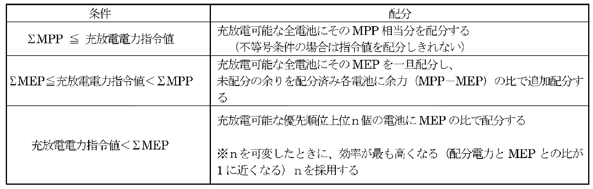
- the distribution ratio determining unit 16 compares the total chargeable / dischargeable power value (MPP) of all the batteries 3-1 to 3-30 with the charge / discharge power command value of the entire system at the time point, and the latter Is greater than or equal to the former, the maximum chargeable / dischargeable power value (MPP) is distributed to all the batteries 3-1 to 3-30. If the latter is larger than the former, the command value cannot be distributed.
- MPP total chargeable / dischargeable power value
- the distribution ratio determining unit 16 determines that the charge / discharge power command value for the entire system at that time is smaller than the total value of the maximum charge / discharge power values (MPP) of all the batteries 3-1 to 3-30. If it is greater than or equal to the sum of the maximum efficiency point power values (MEP) of -1 to 3-30, the MEP is temporarily allocated to all chargeable / dischargeable batteries, and the unallocated remainder is allocated to each allocated battery. Additional allocation is made based on the ratio of remaining power (MPP-MEP).
- the distribution ratio determining unit 16 performs charge / discharge. Distribute to the top n batteries of possible priority by MEP ratio.
- MEP ratio the ratio n between the allocated power and the MEP is closest to 1 and the efficiency n is the highest.
- FIG. 8 shows, as an example, a case (A) distributed to one case, a case (B) distributed to two cases, and a case (C) distributed to three. Proportional distribution.
- the distribution method with the highest efficiency is considered to be either (B) or (C) where the distribution amount is close to MEP. Strictly speaking, as shown in Table 1, the efficiency of both is calculated and determined.
- the charging need value calculation unit 14 of the battery controller 1 obtains specific charging need characteristic data (characteristic values for each SOC value) from the charging need characteristic storage unit 12 for all the batteries 3-1 to 3-30. Obtain the SOC from the SOC data storage unit 11 and calculate the charging need value (step S11).
- the priority calculation unit 15 acquires the charging need value from the charging need value calculation unit 14, and when the charging / discharging power command value of the entire system at the time is in the charging direction, from the battery having a large charging need value, In the discharging direction, prioritization is performed in order from the battery with the smallest charging need value (step S12).
- the distribution ratio determining unit 16 charges / charges all the batteries 3-1 to 3-30.
- the total value of the maximum dischargeable power value (MPP) is compared with the charge / discharge power command value of the entire system at that time (step S13). If the latter is greater than or equal to the former (Yes in step S13), the chargeable / dischargeable maximum power value (MPP) is distributed to all the batteries 3-1 to 3-30 (step S14), and the process is terminated.
- the distribution ratio is determined.
- the unit 16 obtains the maximum efficiency point power values (MEP) of all the batteries 3-1 to 3-30 based on the charge / discharge efficiency characteristics of the batteries 3-1 to 3-30 obtained from the charge / discharge efficiency characteristic storage unit 13. ) And the charge / discharge power command value of the entire system at that time (step S15).
- step S15 If the latter is greater than or equal to the former (Yes in step S15), the highest efficiency point power value (MEP) is once allocated to all the batteries 3-1 to 3-30, and the remaining power (MPP- MEP) is allocated (step S16), and the process ends.
- MEP highest efficiency point power value
- the distribution ratio determining unit 16 distributes the MEP of each battery in priority order (step S17), and sets the priority of the last distribution destination battery to n (step S18).
- the distribution ratio determining unit 16 determines whether or not the distribution amount of the nth battery is smaller than half of the MEP and can be added to the 1st to (n-1) th batteries (step S19).
- the distribution amount of the nth battery is additionally allocated to the (n-1) allocated batteries in the ratio of the remaining power of each battery (MPP-MEP).
- the charge / discharge command value is redistributed to the 1st to nth batteries in the ratio of MEP of each battery (step S21).
- step S20 or step S21 is completed, a battery (including PCS) with zero distributed power is shifted to the low power consumption mode (step S22), and the process ends.
- the distribution ratio determining unit 16 of the battery controller 1 distributes the charging power in preference to the battery having high charging needs. That is, as shown in FIG. 10, since the battery in the position where the charging need curve is high moves to the lower side, the charging needs values of all the batteries 3-1 to 3-30 work in the same direction. On the other hand, when the entire system is in the discharge direction, the discharge power is distributed in preference to the battery with low charging needs. In other words, since the batteries in the position where the charging need curve is low move higher, the charging needs values of all the batteries 3-1 to 3-30 work in the same direction.
- the SOC position (SOC distribution) of each battery for each SOC point As a whole system, it is possible to specify the SOC position (SOC distribution) of each battery for each SOC point as a whole system. Become. For example, in the example of FIG. 10, the battery B has a quick deterioration characteristic in a low SOC region, and thus has a charging need curve as illustrated. As a result, when the system is in the high SOC state, the battery is almost fully charged, and even in the low SOC state as the system, it is possible to always maintain a relatively higher SOC state than the battery A.
- the charge / discharge power command value of the entire system at a certain time can be handled by only one battery. (That is, during low load operation), for example, if power is evenly distributed to three batteries, all the batteries are operated under low-efficiency conditions (dotted line I in FIG. 11).
- the highest efficiency point power is allocated as much as possible in the order of priority determined from the above-described viewpoint of suppressing deterioration, it is distributed to only a small number of batteries with almost the highest efficiency point (Pemax) power (battery 1 in FIG. 11).
- Dotted line II) and the remaining battery group (battery 2 and battery 3) with zero distributed power (dotted line III) can be shifted to a low power consumption standby mode, and the self power consumption of the entire system can be reduced.
- the charging need characteristic is a characteristic expressed by a two-dimensional graph with respect to the SOC (see FIGS. 4 and 10).
- the charging need characteristic can also be expressed by a three-dimensional graph corresponding to both the SOC and temperature parameters.
- the temperature at an arbitrary point in time is uniquely determined, so that the same processing as the distribution method shown in FIG. 9 can be performed by using the charging need characteristic value of the two-dimensional graph corresponding to the temperature. it can.
- Various batteries can be used as the plurality of batteries targeted in the present embodiment.
- the types are not limited to nickel metal hydride batteries, lead storage batteries, and the like, and the capacity (Wh) and output (W) of each battery need not be uniform.
- the distribution method described in the above embodiment can be applied as it is by setting “rated power” described in the embodiment to “maximum chargeable / dischargeable power”.
- the “maximum efficiency point power” is defined as “the maximum efficiency point within a chargeable / dischargeable range”.
- FIG. 10 explains the deterioration suppression effect using the charging needs characteristics when the number of batteries is two
- FIG. 11 increases the charging / discharging efficiency using the charging / discharging efficiency characteristics when the number of batteries is three.
- the number of batteries is arbitrary, it is clear that the same effect can be obtained even if the number of batteries is increased.
Landscapes
- Engineering & Computer Science (AREA)
- Power Engineering (AREA)
- Manufacturing & Machinery (AREA)
- Chemical & Material Sciences (AREA)
- Chemical Kinetics & Catalysis (AREA)
- Electrochemistry (AREA)
- General Chemical & Material Sciences (AREA)
- Charge And Discharge Circuits For Batteries Or The Like (AREA)
- Secondary Cells (AREA)
Abstract
Description
図1に、本発明の一実施形態に係る二次電池システムの構成を示す。
本二次電池システム10は、各電池に対して充放電電力の配分を行う電池コントローラ1と、各電池に接続されて該電池の放充電を行う複数(例えば30個)のPCS2-1~2-30と、該PCS2-1~2-30と1:1に対応して設けられた充放電可能な複数(例えば30個)の電池3-1~3-30と、を備えている。この二次電池システム10においては、多種多様な電池3-1~3-30が、それぞれ対応したPCS2-1~2-30のDC側に接続されるとともに、PCS2-1~2-30のAC側が全て並列接続されて電力系統4に連系接続されている。また、PCS2-1~2-30は、全て電池コントローラ1に接続される。
図2に、電池コントローラ1の詳細な構成を示す。
電池コントローラ1は、SOCデータ保存部11と、充電ニーズ特性保存部12と、充放電効率特性保存部13と、充電ニーズ値算出部14と、優先順位算出部15と、配分割合決定部16とを備えている。電池コントローラ1は、これらの要素によって、定周期毎(例えば1分毎)に、配分先の電池3-1~3-30への優先順位を決定し、この優先順位に従った充放電電力の配分を決定する。
SOCデータ保存部11は、任意の時点での各電池3-1~3-30のSOC(State of Charge:残量)のデータ及びその時点での温度のデータを取得して、保存する。
充電ニーズ特性保存部12は、各電池3-1~3-30について以下で説明するSOC、温度の各値に対する充電ニーズ特性のデータをテーブル形式等として保存する。
充放電効率特性保存部13は、各電池3-1~3-30について以下で説明するあらかじめ効率特性試験を行い、その結果得られた充放電効率特性を保存する。
図5に、特定の種類の電池についての定格電力比で表した充放電電力値と充放電効率との関係を示す。充放電効率は、各電池3-1~3-30とそれに対応したPCS2-1~2-30との組について充放電エネルギー効率、即ち充電したエネルギー(Wh)のうちどれだけが放電で取り出せるかの比率を示すものである。
充電ニーズ値算出部14は、各電池3-1~3-30について、充電ニーズ特性保存部12からその固有の充電ニーズ特性を取得し、SOCデータ保存部11から当該時点のSOCのデータを取得して、充電ニーズ値を算出する。
優先順位算出部15は、電池3-1~3-30の優先順位付けにおいて、電池3-1~3-30の種類毎に予め規定されたSOCに対する「充電ニーズ特性」値を利用する。即ち、優先順位算出部15は、システム全体としての充放電電力値Ptotal(tn)が充電側の場合には当該時点の各電池3-1~3-30の充電ニーズ値が高いものから順に優先順位を付与し、システム全体としての充放電電力値が放電側の場合には当該時点の各電池3-1~3-30の充電ニーズ値が低いものから順に優先順位を付与する。
配分先の電池に対して優先順位が決まった後は、当該順位に従って各電池3-1~3-30に配分する電力値を決める必要がある。配分割合決定方法としては、図6の定格電力比と充放電効率との関係を示すグラフにおいて、最大値である最高効率点電力値(MEP)を基準とし、各電池3-1~3-30に配分する電力値を、図6に示したMEPからMPP(Maximum Power Point:充放電可能最大電力値)の間の値とする手法がある。

上記で説明した方法を考慮した配分割合決定部16における配分割合決定方法を表2に示す。
本実施形態の二次電池システム10による充放電電力配分方法を図9に従って説明する。
以下、本実施形態による効果について、充電ニーズ特性を利用した劣化抑制効果と、充放電効率特性を利用した高充放電効率化とに分けて説明する。
本実施形態の電池コントローラ1の配分割合決定部16は、システム全体が充電方向にあるとき、充電ニーズが高い電池に優先して充電電力を配分する。即ち、図10に示すように、充電ニーズカーブの高い位置にある電池が低い方へ移動するので、全電池3-1~3-30の充電ニーズ値が揃う方向に作用する。他方、システム全体が放電方向にあるとき、充電ニーズが低い電池に優先して放電電力を配分する。即ち、充電ニーズカーブの低い位置にある電池が高い方へ移動するので全電池3-1~3-30の充電ニーズ値が揃う方向に作用する。
次に、充放電効率特性を利用した各電池3-1~3-30への充放電電力配分による損失低減、即ち高充放電効率化について説明する。
(1)上記の実施形態では、充電ニーズ特性はSOCに対する2次元グラフで表現される特性としたが(図4及び図10参照)、一般に電池の劣化にはSOCだけでなく温度も大きく影響する。このため、充電ニーズ特性はSOCと温度の両パラメータに対応した3次元グラフで表現することもできる。但し、この場合においても任意の時点における温度は一義的に決まるため、当該温度に対応した2次元グラフの充電ニーズ特性値を使うことで図9に示した配分方法と同様の処理を行うことができる。
2-1~2-30…PCS(充放電装置)
3-1~3-30…電池
4…電力系統
10…二次電池システム
11…SOCデータ保存部
12…充電ニーズ特性保存部
13…充放電効率特性保存部
14…充電ニーズ値算出部
15…優先順位算出部
16…配分割合決定部
Claims (11)
- 個別に充放電制御可能な複数の電池と、該電池の各々に対応して接続され該電池に充放電を行う複数の充放電装置と、定周期または任意のタイミングでシステム全体としての充放電電力値又は電流値を前記充放電装置の各々に対して配分する電池コントローラとを備え、該電池コントローラは、前記電池の各々のSOCに関する劣化特性に基づいて各時点で前記複数の電池に優先順位付けを行う優先順位算出部と、該優先順位に従い前記充放電装置への充放電電力値又は電流値を配分する配分割合決定部と、を有することを特徴とする複数電池を有する二次電池システム。
- 前記電池コントローラは、さらに、各々の電池の前記劣化特性として、該電池の当該時点のSOCに対する劣化速度を基にした充電ニーズ特性により充電ニーズ値を算出する充電ニーズ値算出部を有することを特徴とする請求項1記載の複数電池を有する二次電池システム。
- 個別に充放電制御可能な複数の電池と、該電池の各々に対応して接続され該電池に充放電を行う複数の充放電装置と、定周期または任意のタイミングでシステム全体としての充放電電力値又は電流値を前記充放電装置の各々に対して配分する電池コントローラとを備え、該電池コントローラにより、前記電池の各々のSOCに関する劣化特性に基づいて各時点で前記複数の電池に優先順位付けを行い、該優先順位に従い前記充放電装置への充放電電力値又は電流値を配分することを特徴とする充放電電力等の配分方法。
- 各々の電池の前記劣化特性として、該電池の当該時点のSOCに対する劣化速度を基にした充電ニーズ特性を用いたことを特徴とする請求項3記載の充放電電力等の配分方法。
- 各々の電池の前記劣化特性として、該電池の当該時点のSOC及び温度に対する劣化速度を基にした充電ニーズ特性を用いたことを特徴とする請求項3記載の充放電電力等の配分方法。
- 各々の電池の前記充電ニーズ特性として、該電池のSOCに対する劣化速度特性のSOCに関する微分値に比例した特性値を用いることを特徴とする請求項4又は5記載の充放電電力等の配分方法。
- 前記優先順位に従った各々の前記充放電装置への充放電電力値の配分において、前記電池及び前記充放電装置の充放電電力に対する効率特性を基にして前記各充放電装置への充放電電力値を配分することを特徴とする請求項3乃至6のいずれか1項に記載の充放電電力等の配分方法。
- 前記優先順位に従った各々の前記充放電装置への充放電電力値の配分において、全電池の充放電可能最大電力値(MPP)の合計値が、当該時点のシステム全体の充放電電力指令値より小さいか等しい場合は、全ての電池にその充放電可能最大電力値(MPP)を配分することを特徴とする請求項7記載の充放電電力等の配分方法。
- 前記優先順位に従った各々の前記充放電装置への充放電電力値の配分において、当該時点のシステム全体の充放電電力指令値が全電池の充放電可能最大電力値(MPP)の合計値より小さく、かつ全電池の最高効率点電力値(MEP)の合計値よりも大きいか等しい場合は、充放電可能な全電池にそのMEPを一旦配分し、未配分の余りを配分済み各電池に余力(MPP-MEP)の比で追加配分することを特徴とする請求項7又は8記載の充放電電力等の配分方法。
- 前記優先順位に従った各々の前記充放電装置への充放電電力値の配分において、当該時点のシステム全体の充放電電力指令値が全電池の最高効率点電力値(MEP)の合計値よりも小さい場合は、配分電力とMEPとの比が最も1に近くなる個数の充放電可能な電池に優先順位が高い順にMEPの比で配分することを特徴とする請求項7乃至9のいずれか1項に記載の充放電電力等の配分方法。
- 充放電電力の配分の結果、配分量がゼロである電池を充放電実施時より消費電力の少ない低消費電力モードにすることを特徴とする請求項3乃至7、及び10のいずれか1項に記載の充放電電力等の配分方法。
Priority Applications (5)
| Application Number | Priority Date | Filing Date | Title |
|---|---|---|---|
| CN201480011705.1A CN105027379B (zh) | 2013-03-04 | 2014-03-03 | 具有多个电池的二次电池系统及充放电功率等的分配方法 |
| KR1020157021555A KR101725701B1 (ko) | 2013-03-04 | 2014-03-03 | 복수 전지를 갖는 이차 전지 시스템 및 충방전 전력 또는 전류의 배분 방법 |
| EP14760676.8A EP2966751B1 (en) | 2013-03-04 | 2014-03-03 | Secondary cell system having plurality of cells, and method for distributing charge/discharge electric power |
| US14/773,144 US9825474B2 (en) | 2013-03-04 | 2014-03-03 | Secondary battery system with plural batteries and method of distributing charge/discharge power |
| ES14760676.8T ES2657417T3 (es) | 2013-03-04 | 2014-03-03 | Sistema de baterías secundarias con una pluralidad de baterías, y procedimiento para distribuir potencia eléctrica de carga/descarga |
Applications Claiming Priority (2)
| Application Number | Priority Date | Filing Date | Title |
|---|---|---|---|
| JP2013042347A JP6157880B2 (ja) | 2013-03-04 | 2013-03-04 | 複数電池を有する二次電池システム及び充放電電力等の配分方法 |
| JP2013-042347 | 2013-03-04 |
Publications (1)
| Publication Number | Publication Date |
|---|---|
| WO2014136705A1 true WO2014136705A1 (ja) | 2014-09-12 |
Family
ID=51491223
Family Applications (1)
| Application Number | Title | Priority Date | Filing Date |
|---|---|---|---|
| PCT/JP2014/055232 Ceased WO2014136705A1 (ja) | 2013-03-04 | 2014-03-03 | 複数電池を有する二次電池システム及び充放電電力等の配分方法 |
Country Status (7)
| Country | Link |
|---|---|
| US (1) | US9825474B2 (ja) |
| EP (1) | EP2966751B1 (ja) |
| JP (1) | JP6157880B2 (ja) |
| KR (1) | KR101725701B1 (ja) |
| CN (1) | CN105027379B (ja) |
| ES (1) | ES2657417T3 (ja) |
| WO (1) | WO2014136705A1 (ja) |
Cited By (9)
| Publication number | Priority date | Publication date | Assignee | Title |
|---|---|---|---|---|
| WO2016185543A1 (ja) * | 2015-05-18 | 2016-11-24 | 三菱電機株式会社 | 電源供給装置および電源供給システム |
| CN106208120A (zh) * | 2016-09-28 | 2016-12-07 | 安徽大学 | 一种混合式储能变流器能量调配控制方法 |
| CN107431368A (zh) * | 2015-03-09 | 2017-12-01 | Fdk株式会社 | 蓄电系统 |
| EP3462567A1 (en) * | 2015-02-26 | 2019-04-03 | Microsoft Technology Licensing, LLC | Load allocation for multi-battery devices |
| WO2020032082A1 (ja) * | 2018-08-07 | 2020-02-13 | 京セラ株式会社 | 制御装置及び制御方法 |
| WO2020080284A1 (ja) * | 2018-10-15 | 2020-04-23 | 京セラ株式会社 | 電力管理装置、電力管理システム及び電力管理方法 |
| JP2020137131A (ja) * | 2019-02-12 | 2020-08-31 | 東芝三菱電機産業システム株式会社 | 蓄電池システム |
| JP2020150740A (ja) * | 2019-03-15 | 2020-09-17 | 大和ハウス工業株式会社 | 電力供給システム |
| US10944132B2 (en) | 2015-02-18 | 2021-03-09 | Microsoft Technology Licensing, Llc | Dynamically changing internal state of a battery |
Families Citing this family (54)
| Publication number | Priority date | Publication date | Assignee | Title |
|---|---|---|---|---|
| JP5998454B2 (ja) * | 2011-11-07 | 2016-09-28 | ソニー株式会社 | 制御装置、制御方法および制御システム |
| JP2014183714A (ja) * | 2013-03-21 | 2014-09-29 | Kddi Corp | 放電制御装置、放電制御方法、およびプログラム |
| JP6419809B2 (ja) | 2014-06-24 | 2018-11-07 | 株式会社東芝 | 蓄電システム及び特性パラメータの推定方法 |
| JP6308303B2 (ja) * | 2014-10-27 | 2018-04-11 | 東芝三菱電機産業システム株式会社 | 蓄電池システム |
| JP6237606B2 (ja) * | 2014-12-19 | 2017-11-29 | トヨタ自動車株式会社 | 電源管理装置 |
| JP6790833B2 (ja) * | 2015-01-15 | 2020-11-25 | 日本電気株式会社 | 蓄電池制御システム、蓄電池制御方法、及び、記録媒体 |
| KR101649816B1 (ko) * | 2015-02-24 | 2016-08-19 | 엘에스산전 주식회사 | 배터리 전력 공급 시스템을 포함하는 전력 공급 시스템 |
| JP6427826B2 (ja) * | 2015-02-27 | 2018-11-28 | 三菱重工業株式会社 | 制御装置、制御方法およびプログラム |
| US20180069270A1 (en) * | 2015-03-16 | 2018-03-08 | Kabushiki Kaisha Toshiba | Storage battery management device, method and computer program product |
| US11144106B2 (en) | 2015-04-13 | 2021-10-12 | Semiconductor Components Industries, Llc | Battery management system for gauging with low power |
| KR101980687B1 (ko) * | 2015-07-28 | 2019-05-22 | 엘에스산전 주식회사 | 에너지 관리 시스템 |
| EP3214724B1 (en) | 2016-03-03 | 2020-04-29 | Lg Chem, Ltd. | Battery energy storage system |
| CN106129509B (zh) * | 2016-06-28 | 2019-07-30 | 北方工业大学 | 一种充放电控制器集成蓄电池 |
| JP2018046667A (ja) * | 2016-09-14 | 2018-03-22 | 株式会社東芝 | 充電パターン作成装置、充電制御装置、充電パターン作成方法、プログラム、及び蓄電システム |
| JP6752286B2 (ja) * | 2016-10-18 | 2020-09-09 | 株式会社日立製作所 | 電池システム |
| CN107054114B (zh) * | 2016-12-08 | 2020-01-03 | 蔚来汽车有限公司 | 动力电池充电功率智能分配方法 |
| KR101904846B1 (ko) * | 2016-12-09 | 2018-10-10 | 효성중공업 주식회사 | Ess 최적 효율 운영방법 |
| JP6596461B2 (ja) * | 2017-04-27 | 2019-10-23 | 株式会社日立パワーソリューションズ | 蓄電池システム、その制御方法および電力安定化システム |
| CN108859795B (zh) * | 2017-05-09 | 2020-09-01 | 郑州宇通客车股份有限公司 | 一种无轨电车充电功率分配方法 |
| JP6917768B2 (ja) * | 2017-05-11 | 2021-08-11 | 株式会社東芝 | 蓄電システム |
| US10790549B2 (en) * | 2017-10-26 | 2020-09-29 | Sunfield Semiconductor Inc. | Method for management of energy storage systems, and related method of operation for smart energy storage cells |
| JP6922820B2 (ja) * | 2018-04-13 | 2021-08-18 | トヨタ自動車株式会社 | 電源制御装置 |
| WO2019230783A1 (ja) * | 2018-05-30 | 2019-12-05 | 京セラ株式会社 | 機器管理サーバ、機器管理システム及び機器管理方法 |
| US10703218B2 (en) | 2018-08-03 | 2020-07-07 | Ford Global Technologies, Llc | System and method for selecting converters to pass non-zero current in distributed converter system |
| JP6968774B2 (ja) | 2018-09-26 | 2021-11-17 | 本田技研工業株式会社 | リチウムイオン電池の制御装置、リチウムイオン電池の制御方法、およびプログラム |
| CN111474480B (zh) * | 2019-01-24 | 2021-11-02 | 宁德时代新能源科技股份有限公司 | 电池阵列状态参数的检测方法、能量管理系统和储能系统 |
| JP7040477B2 (ja) * | 2019-02-08 | 2022-03-23 | 株式会社デンソー | 車両の駆動制御装置および駆動システム |
| US10766371B1 (en) | 2019-02-22 | 2020-09-08 | Ford Global Technologies, Llc | System and method to improve range and fuel economy of electrified vehicles using life balancing |
| KR20210016795A (ko) * | 2019-08-05 | 2021-02-17 | 주식회사 엘지화학 | 에너지 허브 장치 및 에너지 관리 방법 |
| DE102019129415B3 (de) * | 2019-10-31 | 2021-01-14 | Benning CMS Technology GmbH | Verfahren zum Aufladen und/ oder Entladen eines wiederaufladbaren Energiespeichers |
| CN114402519B (zh) | 2019-11-26 | 2025-06-13 | 住友电气工业株式会社 | Dc/dc变换系统、蓄电系统及dc/dc转换器的控制方法 |
| JP7293145B2 (ja) * | 2020-02-04 | 2023-06-19 | 株式会社東芝 | 監視制御装置、蓄電池システム及び方法 |
| CN111313404A (zh) * | 2020-02-28 | 2020-06-19 | 国充充电科技江苏股份有限公司 | 一种充电站的控制方法、系统及电子设备 |
| CN115152119A (zh) * | 2020-03-27 | 2022-10-04 | 本田技研工业株式会社 | 蓄电池系统 |
| KR102450205B1 (ko) | 2020-05-14 | 2022-10-04 | 효성중공업 주식회사 | 전력 공급 시스템의 출력 분배 방법 |
| EP4176505A1 (en) * | 2020-07-01 | 2023-05-10 | Vestas Wind Systems A/S | Battery testing in operation |
| CN111884243B (zh) * | 2020-07-28 | 2022-04-08 | 阳光新能源开发股份有限公司 | 储能调控方法、储能系统及计算机存储介质 |
| WO2022091894A1 (ja) * | 2020-10-27 | 2022-05-05 | パナソニックIpマネジメント株式会社 | 演算システム、充電計画作成プログラム、及び放電計画作成プログラム |
| CN112572218B (zh) * | 2020-12-23 | 2022-03-29 | 尚廉智能科技(上海)有限公司 | 一种节能储能充电桩 |
| KR102882635B1 (ko) * | 2021-01-13 | 2025-11-05 | 주식회사 엘지에너지솔루션 | 배터리 뱅크 전력 제어 장치 및 방법 |
| US20220344959A1 (en) * | 2021-04-27 | 2022-10-27 | China Energy Investment Corporation Limited | Voltage-biased controller, system and method for controlling discharge of heterogeneous battery packs |
| CN113541174B (zh) * | 2021-07-08 | 2024-02-23 | 国网湖南省电力有限公司 | 计及soc排序的储能agc分配pcs有功功率的方法及系统 |
| JP7588045B2 (ja) * | 2021-07-27 | 2024-11-21 | 横河電機株式会社 | コントローラ、制御プログラム、制御方法及び電力供給システム |
| CN113794218B (zh) * | 2021-10-13 | 2023-06-13 | 王勇 | 一种基于升降压电路的电动车退役电池二次利用系统 |
| US12500436B2 (en) * | 2021-10-20 | 2025-12-16 | China Energy Investment Corporation Limited | Controller, system, and method for managing discharge or charge of heterogeneous battery packs |
| KR102812644B1 (ko) * | 2021-12-17 | 2025-05-27 | 포스코홀딩스 주식회사 | 배터리 방전 방법 |
| JP7661263B2 (ja) * | 2022-03-15 | 2025-04-14 | 株式会社東芝 | 電力システム |
| KR102900697B1 (ko) | 2022-03-21 | 2025-12-15 | 주식회사 엘지에너지솔루션 | 신규 설치 배터리 랙의 최적 운영을 위한 에너지 저장 시스템 및 이의 제어 방법 |
| CN116802956A (zh) * | 2022-07-27 | 2023-09-22 | 宁德时代新能源科技股份有限公司 | 充放电控制方法、装置、设备及存储介质 |
| KR20240039281A (ko) * | 2022-09-19 | 2024-03-26 | 주식회사 엘지에너지솔루션 | 신규 설치 배터리를 포함하는 배터리 시스템의 운영 계획 수립 장치 및 방법 |
| JP7691408B2 (ja) * | 2022-11-29 | 2025-06-11 | 矢崎総業株式会社 | 蓄電池制御装置、及び蓄電システム |
| WO2024185073A1 (ja) | 2023-03-08 | 2024-09-12 | 株式会社 東芝 | 電気化学セルに関連する処理方法、処理装置及び処理プログラム |
| JP2025060277A (ja) * | 2023-09-29 | 2025-04-10 | 三菱重工業株式会社 | 電池制御システム、電力需給システム、電池制御方法および電池制御プログラム |
| CN121261366A (zh) * | 2025-12-05 | 2026-01-02 | 南方电网调峰调频发电有限公司储能科研院 | 功率分配方法、控制装置以及液流电池储能系统 |
Citations (6)
| Publication number | Priority date | Publication date | Assignee | Title |
|---|---|---|---|---|
| JP2008118790A (ja) | 2006-11-06 | 2008-05-22 | Hitachi Ltd | 電源制御装置 |
| WO2010084599A1 (ja) * | 2009-01-23 | 2010-07-29 | トヨタ自動車株式会社 | 充電制御装置 |
| WO2011016273A1 (ja) * | 2009-08-04 | 2011-02-10 | 日本電気株式会社 | エネルギーシステム |
| JP2011177025A (ja) | 2011-06-01 | 2011-09-08 | Mitsubishi Heavy Ind Ltd | 組電池システム |
| JP2012210039A (ja) | 2011-03-29 | 2012-10-25 | Denso Corp | 電力分配装置 |
| WO2012176868A1 (ja) * | 2011-06-24 | 2012-12-27 | 三洋電機株式会社 | 電力供給システム |
Family Cites Families (37)
| Publication number | Priority date | Publication date | Assignee | Title |
|---|---|---|---|---|
| JP3890168B2 (ja) * | 1999-08-03 | 2007-03-07 | 株式会社東京アールアンドデー | 電動装置及びその電池ユニットの充放電方法 |
| JP3926114B2 (ja) * | 2001-04-18 | 2007-06-06 | 株式会社マキタ | 複数の充電装置の管理方法 |
| JP3539412B2 (ja) * | 2001-08-09 | 2004-07-07 | 日産自動車株式会社 | 組電池の異常検出装置 |
| JP3949488B2 (ja) * | 2002-03-29 | 2007-07-25 | 本田技研工業株式会社 | 蓄電池の寿命予測装置および蓄電池の制御装置 |
| US7378818B2 (en) * | 2002-11-25 | 2008-05-27 | Tiax Llc | Bidirectional power converter for balancing state of charge among series connected electrical energy storage units |
| US7176656B2 (en) * | 2004-06-22 | 2007-02-13 | Campbell Hausfeld/Scott Fetzer Company | Tool with battery pack |
| JP4186916B2 (ja) * | 2004-11-18 | 2008-11-26 | 株式会社デンソー | 組電池管理装置 |
| US7830117B2 (en) * | 2005-01-10 | 2010-11-09 | Odyne Systems, Llc | Vehicle charging, monitoring and control systems for electric and hybrid electric vehicles |
| FI118656B (fi) * | 2006-05-05 | 2008-01-31 | Finnish Electric Vehicle Techn | Menetelmä ja laitteisto akkukennojen hoitamiseksi |
| US8732896B2 (en) * | 2006-10-17 | 2014-05-27 | Mtd Products Inc | Hybrid electric cleaning device |
| US7797958B2 (en) * | 2006-11-15 | 2010-09-21 | Glacier Bay, Inc. | HVAC system controlled by a battery management system |
| JP4886530B2 (ja) * | 2007-01-24 | 2012-02-29 | パナソニック株式会社 | 電子機器システム及び電池パック |
| JP5096817B2 (ja) * | 2007-07-10 | 2012-12-12 | プライムアースEvエナジー株式会社 | 再構成組電池の製造方法 |
| CA2717789C (en) * | 2007-12-11 | 2018-07-31 | Antonio Trigiani | Battery management system |
| KR20140132775A (ko) * | 2008-03-19 | 2014-11-18 | 클린 에미션스 테크놀로지스, 인코포레이티드 | 전기 견인 시스템 및 방법 |
| JP2012505628A (ja) * | 2008-10-07 | 2012-03-01 | ボストン−パワー,インコーポレイテッド | 車両および他の大容量適用のためのLiイオン電池アレイ |
| KR101000550B1 (ko) * | 2009-11-30 | 2010-12-14 | 정윤이 | 배터리 팩과 이를 포함한 능동형 셀 발란싱 배터리 관리장치 |
| JP5663783B2 (ja) * | 2010-02-26 | 2015-02-04 | リコー電子デバイス株式会社 | 2次電池保護回路とバッテリ装置 |
| JP5640474B2 (ja) * | 2010-06-07 | 2014-12-17 | ソニー株式会社 | 電池システム |
| JP5453184B2 (ja) * | 2010-06-28 | 2014-03-26 | 日立ビークルエナジー株式会社 | 電池制御回路 |
| JP4691198B1 (ja) * | 2010-07-29 | 2011-06-01 | 三菱重工業株式会社 | 移動体用電池システム及び移動体用電池システムの制御方法 |
| JP5842179B2 (ja) * | 2010-08-23 | 2016-01-13 | パナソニックIpマネジメント株式会社 | 電力管理システム |
| US20120319659A1 (en) * | 2010-10-04 | 2012-12-20 | Masahiro Kinoshita | System and method for controlling charge/discharge of non-aqueous electrolyte secondary battery, and battery pack |
| US9568555B2 (en) * | 2010-12-06 | 2017-02-14 | Peter Fredrick Nortman | Electrochemical cell monitoring and balancing circuit with self-diagnostic feature |
| JP5477306B2 (ja) * | 2011-02-16 | 2014-04-23 | アイシン・エィ・ダブリュ株式会社 | 電力分配支援装置、方法およびプログラム |
| WO2012111234A1 (ja) * | 2011-02-18 | 2012-08-23 | 三洋電機株式会社 | 電力供給システム |
| US9847654B2 (en) * | 2011-03-05 | 2017-12-19 | Powin Energy Corporation | Battery energy storage system and control system and applications thereof |
| JP5395116B2 (ja) * | 2011-05-24 | 2014-01-22 | 本田技研工業株式会社 | 燃料電池システムおよびその制御方法 |
| JP5509152B2 (ja) * | 2011-05-31 | 2014-06-04 | 株式会社日立製作所 | 蓄電システム |
| KR101274632B1 (ko) * | 2011-06-08 | 2013-06-13 | 한밭대학교 산학협력단 | 태양광 발전 시스템에서 인버터의 전력 할당 방법 |
| WO2013011758A1 (ja) * | 2011-07-15 | 2013-01-24 | 日本電気株式会社 | 蓄電池システム及びその制御方法 |
| JP5991628B2 (ja) * | 2011-07-28 | 2016-09-14 | パナソニックIpマネジメント株式会社 | バッテリシステム、バッテリ制御装置、電動車両、移動体および電源装置 |
| JP5156112B2 (ja) | 2011-07-28 | 2013-03-06 | 三菱重工業株式会社 | 電池システム |
| US9277298B2 (en) * | 2011-09-20 | 2016-03-01 | Samsung Sdi Co., Ltd. | Battery managing apparatus, battery pack, and energy storage system |
| JP2013247726A (ja) | 2012-05-24 | 2013-12-09 | Toshiba Corp | 蓄電池劣化制御装置 |
| JP2014017982A (ja) * | 2012-07-09 | 2014-01-30 | Toshiba Corp | 充放電電力配分方法、及び電池コントローラ |
| US20140266061A1 (en) * | 2013-03-13 | 2014-09-18 | Manitoba Hydro International Ltd. | Heterogeneous Energy Storage System and Associated Methods |
-
2013
- 2013-03-04 JP JP2013042347A patent/JP6157880B2/ja active Active
-
2014
- 2014-03-03 ES ES14760676.8T patent/ES2657417T3/es active Active
- 2014-03-03 EP EP14760676.8A patent/EP2966751B1/en active Active
- 2014-03-03 US US14/773,144 patent/US9825474B2/en active Active
- 2014-03-03 KR KR1020157021555A patent/KR101725701B1/ko active Active
- 2014-03-03 WO PCT/JP2014/055232 patent/WO2014136705A1/ja not_active Ceased
- 2014-03-03 CN CN201480011705.1A patent/CN105027379B/zh not_active Expired - Fee Related
Patent Citations (6)
| Publication number | Priority date | Publication date | Assignee | Title |
|---|---|---|---|---|
| JP2008118790A (ja) | 2006-11-06 | 2008-05-22 | Hitachi Ltd | 電源制御装置 |
| WO2010084599A1 (ja) * | 2009-01-23 | 2010-07-29 | トヨタ自動車株式会社 | 充電制御装置 |
| WO2011016273A1 (ja) * | 2009-08-04 | 2011-02-10 | 日本電気株式会社 | エネルギーシステム |
| JP2012210039A (ja) | 2011-03-29 | 2012-10-25 | Denso Corp | 電力分配装置 |
| JP2011177025A (ja) | 2011-06-01 | 2011-09-08 | Mitsubishi Heavy Ind Ltd | 組電池システム |
| WO2012176868A1 (ja) * | 2011-06-24 | 2012-12-27 | 三洋電機株式会社 | 電力供給システム |
Non-Patent Citations (1)
| Title |
|---|
| See also references of EP2966751A4 |
Cited By (17)
| Publication number | Priority date | Publication date | Assignee | Title |
|---|---|---|---|---|
| US10944132B2 (en) | 2015-02-18 | 2021-03-09 | Microsoft Technology Licensing, Llc | Dynamically changing internal state of a battery |
| EP3462567A1 (en) * | 2015-02-26 | 2019-04-03 | Microsoft Technology Licensing, LLC | Load allocation for multi-battery devices |
| EP3270485A4 (en) * | 2015-03-09 | 2018-09-19 | FDK Corporation | Electricity storage system |
| CN107431368B (zh) * | 2015-03-09 | 2020-07-07 | Fdk株式会社 | 蓄电系统 |
| CN107431368A (zh) * | 2015-03-09 | 2017-12-01 | Fdk株式会社 | 蓄电系统 |
| WO2016185543A1 (ja) * | 2015-05-18 | 2016-11-24 | 三菱電機株式会社 | 電源供給装置および電源供給システム |
| JPWO2016185543A1 (ja) * | 2015-05-18 | 2017-11-30 | 三菱電機株式会社 | 電源供給システム |
| CN106208120B (zh) * | 2016-09-28 | 2019-04-09 | 安徽新力电业科技咨询有限责任公司 | 一种混合式储能变流器能量调配控制方法 |
| CN106208120A (zh) * | 2016-09-28 | 2016-12-07 | 安徽大学 | 一种混合式储能变流器能量调配控制方法 |
| WO2020032082A1 (ja) * | 2018-08-07 | 2020-02-13 | 京セラ株式会社 | 制御装置及び制御方法 |
| JPWO2020032082A1 (ja) * | 2018-08-07 | 2021-08-10 | 京セラ株式会社 | 制御装置及び制御方法 |
| JP7055208B2 (ja) | 2018-08-07 | 2022-04-15 | 京セラ株式会社 | 制御装置及び制御方法 |
| WO2020080284A1 (ja) * | 2018-10-15 | 2020-04-23 | 京セラ株式会社 | 電力管理装置、電力管理システム及び電力管理方法 |
| JP2020137131A (ja) * | 2019-02-12 | 2020-08-31 | 東芝三菱電機産業システム株式会社 | 蓄電池システム |
| JP7055945B2 (ja) | 2019-02-12 | 2022-04-19 | 東芝三菱電機産業システム株式会社 | 蓄電池システム |
| JP2020150740A (ja) * | 2019-03-15 | 2020-09-17 | 大和ハウス工業株式会社 | 電力供給システム |
| JP7273555B2 (ja) | 2019-03-15 | 2023-05-15 | 大和ハウス工業株式会社 | 電力供給システム |
Also Published As
| Publication number | Publication date |
|---|---|
| CN105027379A (zh) | 2015-11-04 |
| EP2966751B1 (en) | 2017-11-15 |
| KR20150106912A (ko) | 2015-09-22 |
| JP6157880B2 (ja) | 2017-07-05 |
| ES2657417T3 (es) | 2018-03-05 |
| EP2966751A4 (en) | 2016-08-17 |
| US9825474B2 (en) | 2017-11-21 |
| KR101725701B1 (ko) | 2017-04-10 |
| EP2966751A1 (en) | 2016-01-13 |
| JP2014171335A (ja) | 2014-09-18 |
| CN105027379B (zh) | 2018-05-25 |
| US20160013670A1 (en) | 2016-01-14 |
Similar Documents
| Publication | Publication Date | Title |
|---|---|---|
| JP6157880B2 (ja) | 複数電池を有する二次電池システム及び充放電電力等の配分方法 | |
| US10205327B2 (en) | Battery system and energy storage system including distribution controller for selecting battery banks for charging/discharging | |
| JP5975169B2 (ja) | 充放電装置、充放電制御方法、及びプログラム | |
| JP6266187B1 (ja) | 電力変換装置 | |
| WO2019239640A1 (ja) | 蓄電池システムの制御装置および制御方法 | |
| WO2013054672A1 (ja) | 鉛蓄電池システム | |
| US10297877B2 (en) | Storage battery control device and storage battery control method | |
| JP2015167461A (ja) | 太陽光発電システムの制御方法 | |
| JP6439866B2 (ja) | 蓄電装置及び接続制御方法 | |
| WO2013140894A1 (ja) | 調整装置、組電池装置および調整方法 | |
| JP6405754B2 (ja) | 電池制御装置及び電池制御システム | |
| WO2018021151A1 (ja) | 蓄電システム、制御装置、及び蓄電装置 | |
| JP2014236600A (ja) | 系統用蓄電池の複数目的制御装置 | |
| JP6099990B2 (ja) | 蓄電システムおよびその制御方法 | |
| US9608449B2 (en) | Power system and control method of the power system | |
| JP6200086B2 (ja) | 蓄電池制御装置 | |
| WO2017169127A1 (ja) | 二次電池システム | |
| WO2017135170A1 (ja) | 電力貯蔵システムおよびその制御方法 | |
| JP2014236561A (ja) | 二次電池システム及びその制御方法並びに発電システム | |
| JP6917768B2 (ja) | 蓄電システム | |
| JP2017011938A (ja) | グリッド制御装置、グリッド制御システム及びグリッド制御プログラム | |
| CN116961038A (zh) | 微电网的储能量控制方法、装置、计算机设备及存储介质 | |
| JP2015231320A (ja) | 電源バックアップ装置 |
Legal Events
| Date | Code | Title | Description |
|---|---|---|---|
| WWE | Wipo information: entry into national phase |
Ref document number: 201480011705.1 Country of ref document: CN |
|
| 121 | Ep: the epo has been informed by wipo that ep was designated in this application |
Ref document number: 14760676 Country of ref document: EP Kind code of ref document: A1 |
|
| ENP | Entry into the national phase |
Ref document number: 20157021555 Country of ref document: KR Kind code of ref document: A |
|
| NENP | Non-entry into the national phase |
Ref country code: DE |
|
| WWE | Wipo information: entry into national phase |
Ref document number: 14773144 Country of ref document: US |
|
| REEP | Request for entry into the european phase |
Ref document number: 2014760676 Country of ref document: EP |
|
| WWE | Wipo information: entry into national phase |
Ref document number: 2014760676 Country of ref document: EP |