WO2014136946A1 - リチウム二次電池用負極材料及びその製造方法 - Google Patents
リチウム二次電池用負極材料及びその製造方法 Download PDFInfo
- Publication number
- WO2014136946A1 WO2014136946A1 PCT/JP2014/056004 JP2014056004W WO2014136946A1 WO 2014136946 A1 WO2014136946 A1 WO 2014136946A1 JP 2014056004 W JP2014056004 W JP 2014056004W WO 2014136946 A1 WO2014136946 A1 WO 2014136946A1
- Authority
- WO
- WIPO (PCT)
- Prior art keywords
- negative electrode
- iron
- foil
- lithium secondary
- secondary battery
- Prior art date
- Legal status (The legal status is an assumption and is not a legal conclusion. Google has not performed a legal analysis and makes no representation as to the accuracy of the status listed.)
- Ceased
Links
Images





Classifications
-
- H—ELECTRICITY
- H01—ELECTRIC ELEMENTS
- H01M—PROCESSES OR MEANS, e.g. BATTERIES, FOR THE DIRECT CONVERSION OF CHEMICAL ENERGY INTO ELECTRICAL ENERGY
- H01M4/00—Electrodes
- H01M4/02—Electrodes composed of, or comprising, active material
- H01M4/13—Electrodes for accumulators with non-aqueous electrolyte, e.g. for lithium-accumulators; Processes of manufacture thereof
- H01M4/134—Electrodes based on metals, Si or alloys
-
- B—PERFORMING OPERATIONS; TRANSPORTING
- B23—MACHINE TOOLS; METAL-WORKING NOT OTHERWISE PROVIDED FOR
- B23K—SOLDERING OR UNSOLDERING; WELDING; CLADDING OR PLATING BY SOLDERING OR WELDING; CUTTING BY APPLYING HEAT LOCALLY, e.g. FLAME CUTTING; WORKING BY LASER BEAM
- B23K26/00—Working by laser beam, e.g. welding, cutting or boring
- B23K26/352—Working by laser beam, e.g. welding, cutting or boring for surface treatment
-
- H—ELECTRICITY
- H01—ELECTRIC ELEMENTS
- H01M—PROCESSES OR MEANS, e.g. BATTERIES, FOR THE DIRECT CONVERSION OF CHEMICAL ENERGY INTO ELECTRICAL ENERGY
- H01M10/00—Secondary cells; Manufacture thereof
- H01M10/05—Accumulators with non-aqueous electrolyte
- H01M10/052—Li-accumulators
-
- H—ELECTRICITY
- H01—ELECTRIC ELEMENTS
- H01M—PROCESSES OR MEANS, e.g. BATTERIES, FOR THE DIRECT CONVERSION OF CHEMICAL ENERGY INTO ELECTRICAL ENERGY
- H01M10/00—Secondary cells; Manufacture thereof
- H01M10/05—Accumulators with non-aqueous electrolyte
- H01M10/052—Li-accumulators
- H01M10/0525—Rocking-chair batteries, i.e. batteries with lithium insertion or intercalation in both electrodes; Lithium-ion batteries
-
- H—ELECTRICITY
- H01—ELECTRIC ELEMENTS
- H01M—PROCESSES OR MEANS, e.g. BATTERIES, FOR THE DIRECT CONVERSION OF CHEMICAL ENERGY INTO ELECTRICAL ENERGY
- H01M4/00—Electrodes
- H01M4/02—Electrodes composed of, or comprising, active material
- H01M4/36—Selection of substances as active materials, active masses, active liquids
- H01M4/38—Selection of substances as active materials, active masses, active liquids of elements or alloys
-
- H—ELECTRICITY
- H01—ELECTRIC ELEMENTS
- H01M—PROCESSES OR MEANS, e.g. BATTERIES, FOR THE DIRECT CONVERSION OF CHEMICAL ENERGY INTO ELECTRICAL ENERGY
- H01M4/00—Electrodes
- H01M4/02—Electrodes composed of, or comprising, active material
- H01M4/36—Selection of substances as active materials, active masses, active liquids
- H01M4/48—Selection of substances as active materials, active masses, active liquids of inorganic oxides or hydroxides
- H01M4/52—Selection of substances as active materials, active masses, active liquids of inorganic oxides or hydroxides of nickel, cobalt or iron
- H01M4/523—Selection of substances as active materials, active masses, active liquids of inorganic oxides or hydroxides of nickel, cobalt or iron for non-aqueous cells
-
- H—ELECTRICITY
- H01—ELECTRIC ELEMENTS
- H01M—PROCESSES OR MEANS, e.g. BATTERIES, FOR THE DIRECT CONVERSION OF CHEMICAL ENERGY INTO ELECTRICAL ENERGY
- H01M4/00—Electrodes
- H01M4/02—Electrodes composed of, or comprising, active material
- H01M4/64—Carriers or collectors
- H01M4/66—Selection of materials
- H01M4/661—Metal or alloys, e.g. alloy coatings
-
- H—ELECTRICITY
- H01—ELECTRIC ELEMENTS
- H01M—PROCESSES OR MEANS, e.g. BATTERIES, FOR THE DIRECT CONVERSION OF CHEMICAL ENERGY INTO ELECTRICAL ENERGY
- H01M4/00—Electrodes
- H01M4/02—Electrodes composed of, or comprising, active material
- H01M4/64—Carriers or collectors
- H01M4/66—Selection of materials
- H01M4/669—Steels
-
- H—ELECTRICITY
- H01—ELECTRIC ELEMENTS
- H01M—PROCESSES OR MEANS, e.g. BATTERIES, FOR THE DIRECT CONVERSION OF CHEMICAL ENERGY INTO ELECTRICAL ENERGY
- H01M4/00—Electrodes
- H01M4/02—Electrodes composed of, or comprising, active material
- H01M4/64—Carriers or collectors
- H01M4/70—Carriers or collectors characterised by shape or form
-
- H—ELECTRICITY
- H01—ELECTRIC ELEMENTS
- H01M—PROCESSES OR MEANS, e.g. BATTERIES, FOR THE DIRECT CONVERSION OF CHEMICAL ENERGY INTO ELECTRICAL ENERGY
- H01M4/00—Electrodes
- H01M4/02—Electrodes composed of, or comprising, active material
- H01M4/64—Carriers or collectors
- H01M4/70—Carriers or collectors characterised by shape or form
- H01M4/80—Porous plates, e.g. sintered carriers
-
- Y—GENERAL TAGGING OF NEW TECHNOLOGICAL DEVELOPMENTS; GENERAL TAGGING OF CROSS-SECTIONAL TECHNOLOGIES SPANNING OVER SEVERAL SECTIONS OF THE IPC; TECHNICAL SUBJECTS COVERED BY FORMER USPC CROSS-REFERENCE ART COLLECTIONS [XRACs] AND DIGESTS
- Y02—TECHNOLOGIES OR APPLICATIONS FOR MITIGATION OR ADAPTATION AGAINST CLIMATE CHANGE
- Y02E—REDUCTION OF GREENHOUSE GAS [GHG] EMISSIONS, RELATED TO ENERGY GENERATION, TRANSMISSION OR DISTRIBUTION
- Y02E60/00—Enabling technologies; Technologies with a potential or indirect contribution to GHG emissions mitigation
- Y02E60/10—Energy storage using batteries
-
- Y—GENERAL TAGGING OF NEW TECHNOLOGICAL DEVELOPMENTS; GENERAL TAGGING OF CROSS-SECTIONAL TECHNOLOGIES SPANNING OVER SEVERAL SECTIONS OF THE IPC; TECHNICAL SUBJECTS COVERED BY FORMER USPC CROSS-REFERENCE ART COLLECTIONS [XRACs] AND DIGESTS
- Y02—TECHNOLOGIES OR APPLICATIONS FOR MITIGATION OR ADAPTATION AGAINST CLIMATE CHANGE
- Y02P—CLIMATE CHANGE MITIGATION TECHNOLOGIES IN THE PRODUCTION OR PROCESSING OF GOODS
- Y02P70/00—Climate change mitigation technologies in the production process for final industrial or consumer products
- Y02P70/50—Manufacturing or production processes characterised by the final manufactured product
Definitions
- the present invention relates to a negative electrode material for a lithium secondary battery, a method for producing the negative electrode material, and a lithium secondary battery using the negative electrode material.
- negative electrode materials for lithium ion secondary batteries carbon-based materials, graphite-based materials, oxide-based materials such as CoO, Co 3 O 4 , Fe 2 O 3 , Ge 3 N 4 , Zn 3 N 2 , Cu
- metal nitride materials such as 3 N
- Li—Si—M materials such as Mg 2 Si, CrSi 2 , and NiSi, Li metals or Li alloys.
- a graphite-based material was used.
- a nonaqueous electrolyte secondary battery using a metal carbide such as Cr 4 C, VC 2 , Fe 2 C, or FeC as a negative electrode material is also known (Patent Document 1), but the discharge capacity of the test cell is compared. Compared to 350 mAh / g in the case of the graphite negative electrode material of the example, it is about 500 mAh / g, and it is difficult to increase the capacity.
- Non-Patent Document 1 In place of intercalation materials such as carbon-based materials and graphite-based materials, Sn, Si alloyed with Li and these alloy-based negative electrode materials are attracting attention as materials capable of further increasing the capacity and energy density. (Non-Patent Document 1).
- an iron oxide such as Fe 2 O 3 performs a conversion type (decomposition / regeneration type) charge / discharge reaction unlike an intercalation material.
- Fe 2 O 3 As shown by the formula: Fe 2 O 3 + 6Li ⁇ 3Li 2 O + 2Fe, when Li ions are occluded during charging, decomposition occurs with reduction, iron (Fe) and lithium oxide (Li 2 O) are generated, and Li is discharged during discharge. It has been reported that iron ions (Fe 2 O 3 ) are regenerated when ions are desorbed.
- a lithium secondary battery (Patent Document 2) using a negative electrode in which an iron oxide film is provided on a rough surface of a conductive substrate having a rough surface, or a particle size of 1 to 20 ⁇ m.
- Patent Document 3 A patent application has been filed for a lithium secondary battery (Patent Document 3) using an iron oxide powder having a crystallite size of 600 ⁇ or less.
- the negative electrode active material is mixed with a conductive additive or a binder and applied to the negative electrode current collector.
- a conductive additive or a binder As the current collector, aluminum, titanium, copper, iron, stainless steel, or the like is used.
- the main surface of a metal current collector plate such as stainless steel in direct contact with the lithium foil or the lithium alloy foil has a diameter of 20 to 100 ⁇ m and is high or low by laser processing.
- Patent Document 4 A patent application has been filed regarding a lithium battery characterized in that a crater-like spot having a difference of about 0.5 ⁇ m to 5 ⁇ m is formed and roughened (Patent Document 4). It is provided in order to improve the adhesiveness of the lithium foil.
- Laser marking is performed as a process of engraving characters, designs, and patterns on the surface of various materials using a laser.
- a surface treatment method Patent Document 5
- a decorative article having excellent durability and aesthetic appearance is formed by irradiating the surface of Ti or stainless steel with a YVO 4 laser having a spot diameter of 20 to 80 ⁇ m. This method does not form a surface layer having functionality such as a chemical reaction.
- lithium ion secondary batteries mainly use carbon-based or graphite-based materials as negative electrode active materials, and use an electrolytic solution in which LiPF 6 is dissolved in a solvent in which ethylene carbonate and dialkyl carbonate are mixed.
- the intercalation voltage of the material is as low as 0.05 to 0.25V.
- a lithium ion secondary battery using a carbon-based or graphite-based material as a negative electrode active material forms a film with a thickness of about several nanometers called SEI (Solid Electrolyte Interphase) on the negative electrode surface by the first charge.
- SEI Solid Electrolyte Interphase
- lithium ion secondary batteries using Sn, Si or an alloy material thereof as a negative electrode active material have been proposed.
- an alloy negative electrode active material there is an advantage that a high capacity can be obtained and a conventional electrode preparation process using a conductive additive or binder is unnecessary, but these metals change in volume due to insertion and extraction of Li. Therefore, it is pulverized by repeated charge and discharge, the cycle characteristics deteriorate, and it is difficult to extend the life. Therefore, when the alloy-based material is a negative electrode active material, it has been a problem to improve durability while maintaining a high capacity.
- the present invention provides a high-capacity lithium secondary battery that improves the reversibility of charge and discharge by using a material different from the conventional negative electrode material at low cost, and also uses a conventionally used electrolyte. It is an object of the present invention to provide a lithium secondary battery with a low risk of ignition or overheating.
- the inventors of the present invention irradiate a laser beam on the surface of an iron foil or iron-based alloy foil that has been conventionally used as a current collector to form a concave portion having a concave shape such as a hole or a groove on the surface layer portion. If the surface of the foil or the iron-based alloy foil is brought into direct contact with the electrolyte solution for a lithium secondary battery to constitute a lithium secondary battery, a negative electrode in which an active material layer is applied to the current collector surface as in the past is not used.
- the present inventors have found that a lithium secondary battery excellent in high capacity and charge / discharge characteristics can be provided.
- the present invention comprises (1) an iron foil or an iron-based alloy foil having a concave surface-shaped depression formed by heat treatment by laser beam irradiation, and the surface of the surface layer portion is an electrolyte for a lithium secondary battery.
- a negative electrode material for a lithium secondary battery wherein the negative electrode material is a contact surface.
- the present invention is also (2) the negative electrode material for a lithium secondary battery according to (1), wherein the recess is a hole or a groove.
- the present invention provides the negative electrode material for a lithium secondary battery according to the above (1) or (2), wherein the iron foil or the iron-based alloy foil also serves as a negative electrode current collector. is there.
- the thickness of the iron foil or the iron-based alloy foil is 5 ⁇ m to 20 ⁇ m, and the depth from the plane of the edge of the concave-shaped recess to the lowest part of the recess is 0.
- this invention is (5) heat-treating the surface of an iron foil or an iron base alloy foil by irradiating the surface of an iron foil or an iron base alloy foil with a laser beam, and forming the dent of a concave curved surface shape.
- the present invention also provides (6) a negative electrode made of the negative electrode material according to any one of (1) to (4) above, a positive electrode using a lithium compound as an active material, and an electrolytic solution disposed between the positive and negative electrodes And a separator for separating the positive and negative electrodes, and a lithium secondary battery.
- FIG. 1 schematically shows a cross-sectional structure of a lithium secondary battery using the negative electrode material of the present invention, in contrast to the structure of a typical lithium secondary battery of a conventional example.
- a lithium battery is usually composed of a positive electrode made of a positive electrode current collector 1 and a positive electrode active material 2, an electrolyte solution 3, a separator 4, a negative electrode made of a negative electrode active material 5 and a negative electrode current collector 6.
- the negative electrode material does not need to be formed by coating the negative electrode active material layer 5 on the surface thereof.
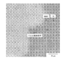
- the negative electrode 7 is composed of only an iron foil or an iron-based alloy foil having a thickness comparable to that of the current collector of the conventional example. When this negative electrode 7 is used, the reaction of the electrolytic solution and the surface layer of the negative electrode iron foil or iron-based alloy foil proceeds, and as shown in the TEM observation image of FIG. A compound layer is formed.
- SEI a film called a film made of a lithium compound such as Li 2 O, Li 2 CO 3 , LiF, etc.
- the lithium ions consumed for the formation of the lithium compound cannot contribute to the charge capacity, and the irreversible capacity during the first charge That is, the difference between the charge capacity and the discharge capacity increases.
- This irreversible capacity increases as the SEI formation amount increases. For this reason, it is desirable to reduce the amount of SEI formed on the negative electrode surface as much as possible.
- the cause of the improvement in reversibility of charge / discharge and the high capacity using an iron foil or iron-base alloy foil having a surface layer formed by laser beam irradiation as a negative electrode material has not been clearly analyzed.
- the conventional Li intercalation phenomenon and Li ion alloying reaction such as Si and Sn-based active materials estimated from the TEM observation result of the interface between the negative electrode and the electrolyte after charging, This is thought to be due to a phenomenon in which the surface of the negative electrode in direct contact with the electrolytic solution chemically reacts with the electrolytic solution during charging to form a thick Li compound layer.
- the Li compound layer formed at the interface between the negative electrode surface of the present invention and the electrolyte without using the carbon material as the negative electrode active material is a conventional SEI film in view of the excellent function on the charge / discharge characteristics and the TEM observation result. Is considered to be essentially different.
- a lithium secondary having excellent charge / discharge characteristics.
- a lithium ion secondary battery that also serves as a current collector and has the functions, corrosion resistance, and heat resistance as a current collector of an iron foil or an iron-based alloy.
- the manufacturing process is simple because steps such as kneading, coating and drying of the negative electrode active material for forming the active material layer on the current collector surface are not required. Thus, the cost can be reduced.
- precipitation of Li metal due to overcharge and discharge is unlikely to occur and it is difficult to ignite, so that a remarkable effect can be obtained such that a safe and large-capacity secondary battery can be realized.
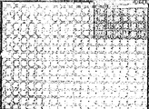
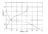
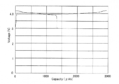
- FIG. 1 It is a cross-sectional schematic diagram which compares and shows the structure of the lithium secondary battery using the prior art example and the negative electrode material of this invention. It is a drawing substitute photograph which shows a SIM image at the time of forming the hole regularly arranged in the shape of a dot by laser beam irradiation on the surface of stainless steel foil. It is a schematic diagram which shows the cross-sectional structure of the shallow crater-shaped hole which is an example of the surface layer part of the negative electrode material of this invention. 3 is a drawing-substituting photograph showing a SIM image of the surface of the stainless steel foil laser-heat treated in Experiment 1. FIG.
- FIG. 2 is a graph showing charge / discharge characteristics of a full cell of Example 1.
- FIG. 4 is a drawing-substituting photograph showing a SIM image of the surface of the electromagnetic soft iron foil laser-heat-treated in Experiment 2.
- FIG. It is a graph which shows the charging / discharging characteristic of the test cell of Experiment 3.
- 4 is a graph showing charge / discharge characteristics of a full cell of Example 2.
- 4 is a drawing-substituting photograph showing an optical microscope image of the surface of the carbon steel foil laser-heat treated in Experiment 3.
- FIG. It is a graph which shows the charging / discharging characteristic of the test cell of Experiment 3.
- 6 is a graph showing the charge / discharge characteristics of the full cell of Example 3.
- the negative electrode material of the present invention is formed by modifying the crystal of the surface layer portion by heat treatment by scanning the surface of the iron foil or iron-based alloy foil with a laser beam.
- This iron foil or iron-based alloy foil can also serve as a negative electrode current collector.
- iron foil used as the negative electrode material of the present invention pure iron foil such as electromagnetic soft iron specified in JIS C2504, carbon steel foil specified in JIS G3141, or the like is used.
- electromagnetic soft iron standards There are four types of electromagnetic soft iron standards, SUY-0 to SUY-3.
- the chemical composition is in mass%, and all are C: 0.03% or less, Mn: 0.50% or less, Si: 0.20% or less, the balance Fe and inevitable impurities.
- SPCC of carbon steel is the most common cold rolled steel, and its chemical composition is mass%, C: 0.15% or less, Mn: 0.60% or less, P: 0.100% or less, S: 0.035%; hereinafter, remaining Fe and inevitable impurities.
- an alloy having an iron content of 50% by weight or more is sometimes called an iron alloy or an iron base.
- Stainless steel is also included in the iron-base alloy.
- iron-based alloy is used in such a meaning.
- the iron-based alloy foil include iron-based alloys such as iron-nickel alloy, iron-chromium alloy, and iron-molybdenum alloy, stainless steel, and low alloy steel.
- Stainless steel includes austenite (SUS304, SUS304-L, SUS302, SUS301, SUS310S, SUS321, SUS316, SUS316-L, etc.) and ferrite stipulated in JIS G4305: 2005 “Cold Rolled Stainless Steel Sheets and Strips” (SUS430, SUS434, etc.), martensite type (SUS410S, SUS420J2, etc.), precipitation hardening type (SUS631, ASL-350, etc.) stainless steel foil, etc.
- the thickness of the iron foil or the iron-based alloy foil is not particularly limited and may be about 1 mm or less, but is preferably about 5 ⁇ m to 100 ⁇ m, which is conventionally used as a current collector, and is practically 5 More preferably, it is 20 ⁇ m.
- gas lasers such as CO 2 laser, Ar laser, or excimer laser
- solid-state lasers such as YAG laser, YLF laser, or YVO 4 laser.
- the YVO 4 laser is capable of single mode oscillation. Since this is possible, it is advantageous to adjust the beam diameter to a minimum and to form highly accurate and finely arranged dots and grooves periodically.
- Laser markers are known as means for forming letters and patterns by irradiating a laser beam on a surface layer of a metal material such as stainless steel.
- the laser marker itself is a processing method that uses a laser beam to evaporate a part of a material surface layer, scratch it, or modify it thermally or chemically.
- the laser marker itself is modified by heat treatment of the present invention. The quality can also be heat-treated using such a commercially available laser marker device as it is.
- a YVO 4 / SHG laser having a wavelength of 532 nm suitable for weak thermal processing is preferable.
- the two-dimensional plane pattern of the concave-curved recess is not particularly limited.
- the recess of the concave curved surface shape is not limited to a shallow crater-shaped hole, but may be a shallow bowl-shaped groove or the like.
- the atmosphere for irradiating the laser beam is not limited, but it may be air in terms of productivity.
- a passive film having a structure composed of a chromium oxide film and a Fe, Cr hydroxide film with a thickness of about 1 to 3 nm is usually provided on the surface.
- the passivated film is removed except for the edge of the concave curved surface that was generated but was not melted by the instantaneous heating of the surface layer of the stainless steel by the laser beam irradiation of the laser marker machine. Is done.
- FIG. 2 shows a SIM image when the holes are regularly arranged in a dot shape by laser beam irradiation on the surface of the stainless steel foil.
- FIG. 3 is a schematic diagram showing a cross section of one hole. As shown in FIG. 3, when a shallow crater-like hole is arranged on the surface of the stainless steel foil as a concave surface-shaped depression, the surface layer portion of the stainless steel 1 is instantaneously melted and deformed by laser heat treatment. A shallow crater-shaped hole having an edge 2 and an inclined portion 3 is formed.
- the surface layer portion of the stainless steel 1 is heat-treated to remove the passive film mainly composed of chromium oxide on the surface of the hole, thereby exposing the crystal plane of the stainless steel substrate and forming the hole.
- the cooling rate is slowed from the edge 2 to the bottom of the hole, and it is presumed that Fe 3 O 4 nanoparticles are generated on the surface of the inclined portion 3 from the edge 2 to the bottom.
- the formation of the concave surface-shaped depression increases the surface area of the negative electrode as compared with the smooth surface, which contributes to increasing the battery capacity.
- the depth D2 from the plane of the edge 2 formed slightly raised from the surface S of the stainless steel foil to the bottom of the recess is not particularly limited, and does not penetrate the stainless steel foil at the maximum.
- the thickness of the stainless steel foil is 5 to 20 ⁇ m which is practical, about 0.5 to 2.5 ⁇ m is preferable.
- the depth can be measured with a laser microscope. Since the effect of modifying the surface layer portion by the heat treatment can be obtained in the heat treatment time when the depth D2 is about 2.5 ⁇ m, it is not necessary to irradiate the laser beam so that the depth D2 becomes deeper than 2.5 ⁇ m. .
- the dot diameter D1 shown in FIG. 3 is about 5 to 20 ⁇ m. It is preferable.
- the interval between adjacent grooves may be the same as in the case of dots.
- the negative electrode material of the present invention is used as a component for a lithium secondary battery. That is, a lithium secondary battery is formed from a negative electrode made of the negative electrode material of the present invention, a positive electrode using a lithium compound as an active material, an electrolyte solution disposed between the positive and negative electrodes, and a separator separating the positive and negative electrodes. can do. There are no particular restrictions on the organic solvent and electrolyte of the electrolytic solution, the positive electrode, the separator, and the structure and size of the outer container constituting the secondary battery, and conventionally known ones can be used.
- the negative electrode material of the present invention can also serve as a negative electrode current collector, it is not necessary to use a separate current collector, but in order to increase conductivity, the surface that comes into contact with the electrolytic solution of iron foil or iron-based alloy foil On the opposite side, a laminate with a conductive foil such as copper or aluminum or a film made of copper or aluminum may be attached.
- the positive electrode current collector may be, for example, aluminum, nickel, or stainless steel.
- the positive electrode active material may be lithium oxide, a composite oxide containing lithium and a transition metal, lithium sulfide, an intercalation compound containing lithium, a lithium phosphate compound, or the like.
- the separator may be a porous film made of polyolefin such as polypropylene (PP) or polyethylene (PE), or a porous film made of ceramic.
- PP polypropylene
- PE polyethylene
- the non-aqueous organic solvent is preferably ethylene carbonate, propylene carbonate, dimethyl carbonate, diethyl carbonate or ethyl methyl carbonate. Fluoroether may be used to improve the flame retardancy of the electrolytic solution.
- the non-aqueous organic solvent may contain an additive such as an organosilicon compound.
- electrolyte salt examples include lithium hexafluorophosphate (LiPF 6 ), lithium tetrafluoroborate (LiBF 4 ), lithium perchlorate (LiClO 4 ), lithium hexafluoroarsenate (LiAsF 6 ), and bis.
- a test cell using the negative electrode material of the present invention was prepared and the state of charge was confirmed.
- a 1 mm thick SUS316 stainless steel foil (NSSC TP-316 manufactured by Nippon Steel & Sumikin Stainless Steel Co., Ltd.) was punched into a square shape with a side of 40 mm to prepare a negative electrode material. The passive film on the stainless steel foil surface was left as it was.
- Laser marker MD-T1010 (manufactured by Keyence Corporation) was used as the laser device.
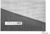
- FIG. 4 shows a SIM observation image of the stainless steel surface heat-treated by laser beam irradiation.
- a coin cell battery was constructed and its charging characteristics were measured.
- As the evaluation equipment a CELLTEST-8 system (1470E) manufactured by Solatron was used.
- a polypropylene-polyethylene-polypropylene microporous three-layer battery separator (Celgard; registered trademark) was used.
- the charging conditions were a constant temperature bath of 60 ° C., and the charging was CC charged at 10 ⁇ A and terminated when 0V was reached.
- FIG. 6 shows the initial charge characteristics of this test cell. The charge capacity was 192.6 ⁇ Ah.
- Example 2 A test cell using the negative electrode material of the present invention was prepared and the discharge state was confirmed.
- the stainless steel foil was irradiated with a laser beam at a laser output of 4 w ⁇ 30% for heat treatment.
- the diameter D1 of the crater-shaped hole was about 20 ⁇ m, and the depth D2 was about 1.5 ⁇ m.
- the depth D2 was measured with a laser microscope VK series.
- a test cell was prepared and evaluated under the same conditions as in Experiment 1 except that the obtained stainless steel foil was used as the negative electrode.
- the charge / discharge conditions were a constant temperature bath of 60 ° C., the charge was CC charged at 10 ⁇ A, terminated when 0V was reached, paused for 10 minutes, the discharge was CC discharged at 10 ⁇ A, and terminated when 2.5V was reached.
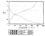
- FIG. 7 shows the initial charge / discharge characteristics of this test cell. A large capacity of 555.0 ⁇ Ah for charge capacity and 483.9 ⁇ Ah for discharge capacity was obtained.
- a full cell was produced using the negative electrode produced in Experiment 2.
- a battery container made of stainless steel with a separator sandwiched on both sides as a positive electrode on both sides so that the capacity is 1.6 mAh / cm 2, and using the stainless steel foil prepared in Experiment 2 as the negative electrode for the electrolyte
- the aluminum current collector was brought into contact with the positive electrode, and the aluminum current collector was further brought into contact with the battery container.
- the negative electrode material also served as the negative electrode current collector and was brought into contact with the battery container as it was.
- the separator, electrolyte solution, and electrolyte were the same as those in Experiments 1 and 2.
- the charge / discharge conditions were a constant temperature bath of 25 ° C., the charge was CC charge at 30 ⁇ A, and charge / discharge was performed at a charge / discharge voltage of 4.3 to 2.5V.
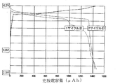
- FIG. 9 shows the charge / discharge characteristics of the full cell.
- the charge capacity in the first cycle was 1467 ⁇ Ah
- the discharge capacity was 1466 ⁇ Ah
- the charge capacity in the second cycle was 1458 ⁇ Ah
- the discharge capacity was 1441 ⁇ Ah.
- the irreversible capacity could be greatly reduced, and the initial charge / discharge efficiency was almost 100%.
- FIG. 10 shows a SIM observation image of the surface of the electromagnetic soft iron foil that has been heat-treated by laser beam irradiation.
- the electromagnetic soft iron foil obtained by the above method is punched into a disk shape with a diameter of 16 mm, and a negative electrode that also serves as a negative electrode current collector is used to produce a test cell and measure charge / discharge capacity under the same conditions as in Experiment 1 and Experiment 2. went.
- FIG. 11 shows the charge / discharge results of this test cell.
- the first, second, and third charge capacities were 49 ⁇ Ah, 26 ⁇ Ah, and 23 ⁇ Ah, respectively, and the discharge capacities were 24 ⁇ Ah, 21 ⁇ Ah, and 19 ⁇ Ah, respectively.
- Example 3 Using the negative electrode produced in Experiment 3, a full cell was produced under the same conditions as in Example 1 except that the lithium cobalt oxide had a capacity of 3 mAh / cm 2, and the charge / discharge characteristics were evaluated.
- FIG. 12 shows the charge / discharge characteristics of the full cell.
- the first, second and third charge capacities were 4783 ⁇ Ah, 3169 ⁇ Ah and 2080 ⁇ Ah, respectively, and the discharge capacities were 2608 ⁇ Ah, 1882 ⁇ Ah and 1268 ⁇ Ah, respectively.
- a 1 mm thick cold rolled steel foil (SPCC JIS G 3141) was punched into a square shape with a side of 50 mm to prepare a negative electrode material.
- Laser marker SUNX LP-Z250 (Panasonic Electric Works Co., Ltd.) was used as the laser device.
- a YAG laser with a wavelength of 532 nm, an average output of 1 W, and a printing speed of up to 12000 mm / s, with a laser power of 1 w, a scanning speed of 120 mm / s, and a printing pulse of 10 ⁇ s, a crater-like shallow hole is regularly and horizontally opened as in Experiment 1. It was.
- FIG. 13 shows an optical microscope observation image of the surface of the cold rolled steel foil that has been heat-treated by laser beam irradiation.
- the cold-rolled steel foil obtained by the above method is punched into a disk shape with a diameter of 16 mm, and a negative electrode that also serves as a negative electrode current collector is prepared under the same conditions as in Experiments 1 to 3, with test cell preparation and charge / discharge capacity. Measurements were made.
- FIG. 14 shows the charge / discharge results of this test cell. The first charge capacity was 65 ⁇ Ah, and the discharge capacity was 43 ⁇ Ah. *
- Example 4 Using the negative electrode produced in Experiment 4, a full cell was produced under the same conditions as in Example 1 except that the lithium cobalt oxide had a capacity of 3 mAh / cm 2, and the charge / discharge characteristics were evaluated.
- FIG. 15 shows the charge / discharge characteristics of the full cell. The first charge capacity was 2960 ⁇ Ah, and the discharge capacity was 1344 ⁇ Ah.
- the negative electrode material of the present invention can be easily manufactured by using a general iron foil or iron-based alloy foil and a laser marking technique, and includes a process of applying an expensive active material as in the prior art to the negative electrode surface. It is expected to be used as an innovative new negative electrode material that can be manufactured at low cost because it is unnecessary, has excellent heat resistance, improves the safety and reliability of lithium secondary batteries, and can achieve high capacity.
Landscapes
- Chemical & Material Sciences (AREA)
- Chemical Kinetics & Catalysis (AREA)
- Electrochemistry (AREA)
- General Chemical & Material Sciences (AREA)
- Engineering & Computer Science (AREA)
- Materials Engineering (AREA)
- Manufacturing & Machinery (AREA)
- Inorganic Chemistry (AREA)
- Physics & Mathematics (AREA)
- Mechanical Engineering (AREA)
- Plasma & Fusion (AREA)
- Optics & Photonics (AREA)
- Cell Electrode Carriers And Collectors (AREA)
- Battery Electrode And Active Subsutance (AREA)
- Secondary Cells (AREA)
Abstract
Description
また、本発明は、(2)該窪みは、孔又は溝であることを特徴とする上記(1)のリチウム二次電池用負極材料、である。
また、本発明は、(3)該鉄箔又は鉄基合金箔は、負極集電体を兼ねていることを特徴とする上記(1)又は(2)のリチウム二次電池用負極材料、である。
また、本発明は、(4)該鉄箔又は鉄基合金箔の厚みが5μm~20μmであり、該凹曲面形状の窪みの縁部の平面から該窪みの最低部までの深さが0.5μm~2.5μmであることを特徴とする上記(1)~(3)のいずれかのリチウム二次電池用負極材料、である。
[実験1]
本発明の負極材料を用いる試験セルを作製して放電状態を確認した。レーザー出力を4w×30%としてステンレス鋼箔にレーザービーム照射して熱処理した。クレーター状の孔の直径D1は約20μm、深さD2は約1.5μmであった。深さD2はレーザー顕微鏡VKシリーズにて測定した。得られたステンレス鋼箔を負極として用いた以外は、実験1と同じ条件で試験セルを作成し、評価した。
[実験3]
[実験4]
Claims (6)
- レーザービーム照射により熱処理されて形成された凹曲面形状の窪みを有する鉄箔又は鉄基合金箔からなり、該表層部の表面がリチウム二次電池用電解液と接触する表面であることを特徴とするリチウム二次電池用負極材料。
- 該窪みは、孔又は溝であることを特徴とする請求項1記載のリチウム二次電池用負極材料。
- 該鉄箔又は鉄基合金箔は、負極集電体を兼ねていることを特徴とする請求項1又は2に記載のリチウム二次電池用負極材料。
- 該鉄箔又は鉄基合金箔の厚みが5μm~20μmであり、該凹曲面形状の窪みの縁部の平面から該窪みの最低部までの深さが0.5μm~2.5μmであることを特徴とする請求項1~3のいずれかに記載のリチウム二次電池用負極材料。
- 鉄箔又は鉄基合金箔の表面にレーザービームを照射して走査することにより鉄箔又は鉄基合金箔表面を熱処理して凹曲面形状の窪みを形成することを特徴とする請求項1~4のいずれかに記載のリチウム二次電池用負極材料の製造方法。
- 請求項1~4のいずれかに記載の負極材料からなる負極と、リチウム化合物を活物質とする正極と、この正負極間に配置される電解液と、正負極間を隔離するセパレータと、からなることを特徴とするリチウム二次電池。
Priority Applications (5)
| Application Number | Priority Date | Filing Date | Title |
|---|---|---|---|
| CN201480000857.1A CN104221188A (zh) | 2013-03-08 | 2014-03-07 | 锂二次电池用负极材料及其制造方法 |
| JP2014537204A JP6295200B2 (ja) | 2013-03-08 | 2014-03-07 | リチウム二次電池用負極材料の製造方法 |
| US14/384,907 US9614215B2 (en) | 2013-03-08 | 2014-03-07 | Negative electrode material for lithium secondary battery and method for manufacturing the same |
| KR1020147023430A KR20150128538A (ko) | 2013-03-08 | 2014-03-07 | 리튬 이차전지용 부극 재료 및 그 제조 방법 |
| EP14761206.3A EP2833443A4 (en) | 2013-03-08 | 2014-03-07 | NEGATIVE ELECTRODE MATERIAL FOR LITHIUM SECONDARY BATTERIES AND METHOD FOR THE PRODUCTION THEREOF |
Applications Claiming Priority (2)
| Application Number | Priority Date | Filing Date | Title |
|---|---|---|---|
| JP2013-047306 | 2013-03-08 | ||
| JP2013047306 | 2013-03-08 |
Publications (1)
| Publication Number | Publication Date |
|---|---|
| WO2014136946A1 true WO2014136946A1 (ja) | 2014-09-12 |
Family
ID=51491453
Family Applications (1)
| Application Number | Title | Priority Date | Filing Date |
|---|---|---|---|
| PCT/JP2014/056004 Ceased WO2014136946A1 (ja) | 2013-03-08 | 2014-03-07 | リチウム二次電池用負極材料及びその製造方法 |
Country Status (7)
| Country | Link |
|---|---|
| US (1) | US9614215B2 (ja) |
| EP (1) | EP2833443A4 (ja) |
| JP (1) | JP6295200B2 (ja) |
| KR (1) | KR20150128538A (ja) |
| CN (1) | CN104221188A (ja) |
| TW (1) | TW201444159A (ja) |
| WO (1) | WO2014136946A1 (ja) |
Cited By (1)
| Publication number | Priority date | Publication date | Assignee | Title |
|---|---|---|---|---|
| KR20190033642A (ko) * | 2017-03-17 | 2019-03-29 | 히타치 긴조쿠 가부시키가이샤 | 이차 전지의 부극 집전체용 박 및 그 제조 방법 |
Families Citing this family (12)
| Publication number | Priority date | Publication date | Assignee | Title |
|---|---|---|---|---|
| EP3353844B1 (en) | 2015-03-27 | 2022-05-11 | Mason K. Harrup | All-inorganic solvents for electrolytes |
| US10707531B1 (en) | 2016-09-27 | 2020-07-07 | New Dominion Enterprises Inc. | All-inorganic solvents for electrolytes |
| KR102119705B1 (ko) * | 2016-10-14 | 2020-06-08 | 주식회사 엘지화학 | 이차전지용 음극 |
| WO2018070843A2 (ko) * | 2016-10-14 | 2018-04-19 | 주식회사 엘지화학 | 이차전지용 음극 |
| JP6987780B2 (ja) * | 2016-11-29 | 2022-01-05 | 三洋電機株式会社 | 非水電解質二次電池 |
| US10892671B2 (en) * | 2017-07-25 | 2021-01-12 | GM Global Technology Operations LLC | Electrically conductive copper components and joining processes therefor |
| US11171362B2 (en) * | 2017-09-12 | 2021-11-09 | Sila Nanotechnologies, Inc. | Electrolyte for a metal-ion battery cell with high-capacity, micron-scale, volume-changing anode particles |
| CN110085806B (zh) * | 2019-04-30 | 2022-10-18 | 湖北锂诺新能源科技有限公司 | 硅碳负极及其制备方法与锂离子电池 |
| JP7057766B2 (ja) * | 2019-07-09 | 2022-04-20 | Jfeスチール株式会社 | 硫化物系固体電池の集電体用のフェライト系ステンレス鋼板およびその製造方法 |
| KR20230038641A (ko) * | 2020-07-16 | 2023-03-21 | 도요 고한 가부시키가이샤 | 전해철박 |
| US12525599B2 (en) | 2021-12-21 | 2026-01-13 | Our Next Energy, Inc. | Manufacturing battery electrodes |
| CN118117174A (zh) * | 2022-11-29 | 2024-05-31 | 深圳新宙邦科技股份有限公司 | 一种锂离子电池 |
Citations (7)
| Publication number | Priority date | Publication date | Assignee | Title |
|---|---|---|---|---|
| JPH0348953B2 (ja) | 1984-11-08 | 1991-07-26 | Canon Kk | |
| JPH1050299A (ja) | 1996-05-31 | 1998-02-20 | Matsushita Electric Ind Co Ltd | 非水電解質二次電池 |
| JP2003138384A (ja) | 2001-10-30 | 2003-05-14 | Seiko Epson Corp | 表面処理方法および装飾品 |
| JP2005158397A (ja) | 2003-11-25 | 2005-06-16 | Ngk Spark Plug Co Ltd | リチウム電池およびその製造方法 |
| JP2006066696A (ja) * | 2004-08-27 | 2006-03-09 | Tdk Corp | 電気化学素子 |
| JP2011029139A (ja) | 2009-06-24 | 2011-02-10 | Toyota Motor Corp | リチウム二次電池及びその製造方法 |
| JP2011129344A (ja) | 2009-12-17 | 2011-06-30 | Toyota Motor Corp | リチウムイオン二次電池 |
Family Cites Families (4)
| Publication number | Priority date | Publication date | Assignee | Title |
|---|---|---|---|---|
| KR100659816B1 (ko) * | 2002-04-26 | 2006-12-19 | 미츠이 마이닝 & 스멜팅 콤파니 리미티드 | 비수 전해액 이차전지용 음극 및 그 제조방법 그리고 비수전해액 이차전지 |
| JP4037229B2 (ja) | 2002-09-30 | 2008-01-23 | 日立マクセル株式会社 | リチウム二次電池用電極と、これを負極とするリチウム二次電池 |
| JP2004342519A (ja) * | 2003-05-16 | 2004-12-02 | M & G Eco Battery Institute Co Ltd | ペースト式薄型電極を用いた電池とその製造方法 |
| JP2005025978A (ja) * | 2003-06-30 | 2005-01-27 | Sanyo Electric Co Ltd | リチウム二次電池用電極及びリチウム二次電池 |
-
2014
- 2014-03-07 TW TW103107797A patent/TW201444159A/zh unknown
- 2014-03-07 US US14/384,907 patent/US9614215B2/en not_active Expired - Fee Related
- 2014-03-07 JP JP2014537204A patent/JP6295200B2/ja not_active Expired - Fee Related
- 2014-03-07 WO PCT/JP2014/056004 patent/WO2014136946A1/ja not_active Ceased
- 2014-03-07 CN CN201480000857.1A patent/CN104221188A/zh active Pending
- 2014-03-07 EP EP14761206.3A patent/EP2833443A4/en not_active Withdrawn
- 2014-03-07 KR KR1020147023430A patent/KR20150128538A/ko not_active Withdrawn
Patent Citations (7)
| Publication number | Priority date | Publication date | Assignee | Title |
|---|---|---|---|---|
| JPH0348953B2 (ja) | 1984-11-08 | 1991-07-26 | Canon Kk | |
| JPH1050299A (ja) | 1996-05-31 | 1998-02-20 | Matsushita Electric Ind Co Ltd | 非水電解質二次電池 |
| JP2003138384A (ja) | 2001-10-30 | 2003-05-14 | Seiko Epson Corp | 表面処理方法および装飾品 |
| JP2005158397A (ja) | 2003-11-25 | 2005-06-16 | Ngk Spark Plug Co Ltd | リチウム電池およびその製造方法 |
| JP2006066696A (ja) * | 2004-08-27 | 2006-03-09 | Tdk Corp | 電気化学素子 |
| JP2011029139A (ja) | 2009-06-24 | 2011-02-10 | Toyota Motor Corp | リチウム二次電池及びその製造方法 |
| JP2011129344A (ja) | 2009-12-17 | 2011-06-30 | Toyota Motor Corp | リチウムイオン二次電池 |
Non-Patent Citations (2)
| Title |
|---|
| See also references of EP2833443A4 * |
| TETSUO SAKAI: "Development of Alloy-Based Negative Electrodes Prepared by Nano-Designing of Materials for Advanced Lithium Ion Batteries", DENKI-SEIKO, vol. 77, no. 4, December 2006 (2006-12-01), pages 301 - 309 |
Cited By (2)
| Publication number | Priority date | Publication date | Assignee | Title |
|---|---|---|---|---|
| KR20190033642A (ko) * | 2017-03-17 | 2019-03-29 | 히타치 긴조쿠 가부시키가이샤 | 이차 전지의 부극 집전체용 박 및 그 제조 방법 |
| KR101997428B1 (ko) | 2017-03-17 | 2019-07-05 | 히타치 긴조쿠 가부시키가이샤 | 이차 전지의 부극 집전체용 박 및 그 제조 방법 |
Also Published As
| Publication number | Publication date |
|---|---|
| CN104221188A (zh) | 2014-12-17 |
| JPWO2014136946A1 (ja) | 2017-02-16 |
| EP2833443A4 (en) | 2016-01-20 |
| KR20150128538A (ko) | 2015-11-18 |
| EP2833443A1 (en) | 2015-02-04 |
| TW201444159A (zh) | 2014-11-16 |
| US20150037675A1 (en) | 2015-02-05 |
| JP6295200B2 (ja) | 2018-03-14 |
| US9614215B2 (en) | 2017-04-04 |
Similar Documents
| Publication | Publication Date | Title |
|---|---|---|
| JP6295200B2 (ja) | リチウム二次電池用負極材料の製造方法 | |
| JP3866740B2 (ja) | 非水電解質二次電池、組電池及び電池パック | |
| JP4306697B2 (ja) | 二次電池 | |
| JP3676301B2 (ja) | リチウム二次電池用電極及びリチウム二次電池 | |
| US10622621B2 (en) | Methods for making patterned, thick, silicon-containing electrodes | |
| CN112805854B (zh) | 非水电解液二次电池用负极活性物质、负极、电池以及覆铝金属层叠体 | |
| KR101701785B1 (ko) | 리튬 이온 이차전지용 집전체 및 리튬 이온 이차전지용 양극 | |
| JP2008098151A (ja) | 非水電解質二次電池及びその製造方法 | |
| JPWO2017047280A1 (ja) | リチウム二次電池及びその製造方法 | |
| EP4456184A1 (en) | Positive active material for rechargeable lithium battery, method of preparing same, and rechargeable lithium battery including same | |
| JP2005197002A (ja) | リチウムイオン二次電池 | |
| CN111630694A (zh) | 非水电解液二次电池用负极活性物质、负极以及电池 | |
| JP2010287470A (ja) | 非水二次電池およびその製造方法 | |
| EP2445050B1 (en) | Electricity-generating element and nonaqueous-electrolyte battery using the same | |
| JP6536515B2 (ja) | リチウムイオン電池およびリチウムイオン電池の製造方法 | |
| JP2010114093A (ja) | 電極集電体及びその製造方法、電池用電極及びその製造方法、並びに二次電池 | |
| JP2013097925A (ja) | リチウム二次電池の電極の製造方法、リチウム二次電池の電極及びリチウム二次電池 | |
| JP2009218112A (ja) | 非水電解質二次電池及びその製造方法 | |
| EP4210124A2 (en) | Electrode, secondary battery, and electrode manufacturing method | |
| KR20180023547A (ko) | 리튬 전극의 제조방법 및 이로부터 제조된 리튬 전극 | |
| JP2007214086A (ja) | 電池用電極及びそれを用いた電池 | |
| JP2008235083A (ja) | リチウム二次電池用負極及びリチウム二次電池 | |
| JP2007052935A (ja) | 非水電解質電池 | |
| JP7485643B2 (ja) | レーザー加工された正極の製造方法 | |
| JP2016015245A (ja) | リチウムイオン二次電池 |
Legal Events
| Date | Code | Title | Description |
|---|---|---|---|
| ENP | Entry into the national phase |
Ref document number: 2014537204 Country of ref document: JP Kind code of ref document: A |
|
| ENP | Entry into the national phase |
Ref document number: 20147023430 Country of ref document: KR Kind code of ref document: A |
|
| WWE | Wipo information: entry into national phase |
Ref document number: 14384907 Country of ref document: US |
|
| WWE | Wipo information: entry into national phase |
Ref document number: 2014761206 Country of ref document: EP |
|
| 121 | Ep: the epo has been informed by wipo that ep was designated in this application |
Ref document number: 14761206 Country of ref document: EP Kind code of ref document: A1 |
|
| NENP | Non-entry into the national phase |
Ref country code: DE |