WO2014136987A1 - Electrophotographic photosensitive member, process cartridge, electrophotographic apparatus, and condensed polycyclic aromatic compound - Google Patents
Electrophotographic photosensitive member, process cartridge, electrophotographic apparatus, and condensed polycyclic aromatic compound Download PDFInfo
- Publication number
- WO2014136987A1 WO2014136987A1 PCT/JP2014/056587 JP2014056587W WO2014136987A1 WO 2014136987 A1 WO2014136987 A1 WO 2014136987A1 JP 2014056587 W JP2014056587 W JP 2014056587W WO 2014136987 A1 WO2014136987 A1 WO 2014136987A1
- Authority
- WO
- WIPO (PCT)
- Prior art keywords
- photosensitive member
- group
- electrophotographic photosensitive
- hole transporting
- reactive functional
- Prior art date
- Legal status (The legal status is an assumption and is not a legal conclusion. Google has not performed a legal analysis and makes no representation as to the accuracy of the status listed.)
- Ceased
Links
- 0 CCC1(*)c2cc(-c(cc3C(CC)(CC)c4c5)ccc3-c4ccc5-c(cc3)cc(C4(*)CC)c3-c3c4cc(*)cc3)ccc2-c2c1cccc2 Chemical compound CCC1(*)c2cc(-c(cc3C(CC)(CC)c4c5)ccc3-c4ccc5-c(cc3)cc(C4(*)CC)c3-c3c4cc(*)cc3)ccc2-c2c1cccc2 0.000 description 6
Classifications
-
- G—PHYSICS
- G03—PHOTOGRAPHY; CINEMATOGRAPHY; ANALOGOUS TECHNIQUES USING WAVES OTHER THAN OPTICAL WAVES; ELECTROGRAPHY; HOLOGRAPHY
- G03G—ELECTROGRAPHY; ELECTROPHOTOGRAPHY; MAGNETOGRAPHY
- G03G5/00—Recording-members for original recording by exposure, e.g. to light, to heat or to electrons; Manufacture thereof; Selection of materials therefor
- G03G5/02—Charge-receiving layers
- G03G5/04—Photoconductive layers; Charge-generation layers or charge-transporting layers; Additives therefor; Binders therefor
- G03G5/06—Photoconductive layers; Charge-generation layers or charge-transporting layers; Additives therefor; Binders therefor characterised by the photoconductive material being organic
- G03G5/0622—Heterocyclic compounds
- G03G5/0644—Heterocyclic compounds containing two or more hetero rings
- G03G5/0646—Heterocyclic compounds containing two or more hetero rings in the same ring system
- G03G5/0648—Heterocyclic compounds containing two or more hetero rings in the same ring system containing two relevant rings
-
- C—CHEMISTRY; METALLURGY
- C07—ORGANIC CHEMISTRY
- C07C—ACYCLIC OR CARBOCYCLIC COMPOUNDS
- C07C39/00—Compounds having at least one hydroxy or O-metal group bound to a carbon atom of a six-membered aromatic ring
- C07C39/02—Compounds having at least one hydroxy or O-metal group bound to a carbon atom of a six-membered aromatic ring monocyclic with no unsaturation outside the aromatic ring
- C07C39/04—Phenol
-
- C—CHEMISTRY; METALLURGY
- C07—ORGANIC CHEMISTRY
- C07C—ACYCLIC OR CARBOCYCLIC COMPOUNDS
- C07C39/00—Compounds having at least one hydroxy or O-metal group bound to a carbon atom of a six-membered aromatic ring
- C07C39/12—Compounds having at least one hydroxy or O-metal group bound to a carbon atom of a six-membered aromatic ring polycyclic with no unsaturation outside the aromatic rings
- C07C39/17—Compounds having at least one hydroxy or O-metal group bound to a carbon atom of a six-membered aromatic ring polycyclic with no unsaturation outside the aromatic rings containing other rings in addition to the six-membered aromatic rings, e.g. cyclohexylphenol
-
- C—CHEMISTRY; METALLURGY
- C07—ORGANIC CHEMISTRY
- C07C—ACYCLIC OR CARBOCYCLIC COMPOUNDS
- C07C69/00—Esters of carboxylic acids; Esters of carbonic or haloformic acids
- C07C69/52—Esters of acyclic unsaturated carboxylic acids having the esterified carboxyl group bound to an acyclic carbon atom
- C07C69/533—Monocarboxylic acid esters having only one carbon-to-carbon double bond
-
- C—CHEMISTRY; METALLURGY
- C07—ORGANIC CHEMISTRY
- C07C—ACYCLIC OR CARBOCYCLIC COMPOUNDS
- C07C69/00—Esters of carboxylic acids; Esters of carbonic or haloformic acids
- C07C69/52—Esters of acyclic unsaturated carboxylic acids having the esterified carboxyl group bound to an acyclic carbon atom
- C07C69/602—Dicarboxylic acid esters having at least two carbon-to-carbon double bonds
-
- C—CHEMISTRY; METALLURGY
- C07—ORGANIC CHEMISTRY
- C07D—HETEROCYCLIC COMPOUNDS
- C07D303/00—Compounds containing three-membered rings having one oxygen atom as the only ring hetero atom
- C07D303/02—Compounds containing oxirane rings
- C07D303/12—Compounds containing oxirane rings with hydrocarbon radicals, substituted by singly or doubly bound oxygen atoms
- C07D303/18—Compounds containing oxirane rings with hydrocarbon radicals, substituted by singly or doubly bound oxygen atoms by etherified hydroxyl radicals
- C07D303/28—Ethers with hydroxy compounds containing oxirane rings
-
- C—CHEMISTRY; METALLURGY
- C07—ORGANIC CHEMISTRY
- C07D—HETEROCYCLIC COMPOUNDS
- C07D305/00—Heterocyclic compounds containing four-membered rings having one oxygen atom as the only ring hetero atoms
- C07D305/02—Heterocyclic compounds containing four-membered rings having one oxygen atom as the only ring hetero atoms not condensed with other rings
- C07D305/04—Heterocyclic compounds containing four-membered rings having one oxygen atom as the only ring hetero atoms not condensed with other rings having no double bonds between ring members or between ring members and non-ring members
- C07D305/06—Heterocyclic compounds containing four-membered rings having one oxygen atom as the only ring hetero atoms not condensed with other rings having no double bonds between ring members or between ring members and non-ring members with only hydrogen atoms, hydrocarbon or substituted hydrocarbon radicals, directly attached to the ring atoms
-
- C—CHEMISTRY; METALLURGY
- C07—ORGANIC CHEMISTRY
- C07D—HETEROCYCLIC COMPOUNDS
- C07D307/00—Heterocyclic compounds containing five-membered rings having one oxygen atom as the only ring hetero atom
- C07D307/77—Heterocyclic compounds containing five-membered rings having one oxygen atom as the only ring hetero atom ortho- or peri-condensed with carbocyclic rings or ring systems
- C07D307/91—Dibenzofurans; Hydrogenated dibenzofurans
-
- C—CHEMISTRY; METALLURGY
- C07—ORGANIC CHEMISTRY
- C07D—HETEROCYCLIC COMPOUNDS
- C07D309/00—Heterocyclic compounds containing six-membered rings having one oxygen atom as the only ring hetero atom, not condensed with other rings
- C07D309/02—Heterocyclic compounds containing six-membered rings having one oxygen atom as the only ring hetero atom, not condensed with other rings having no double bonds between ring members or between ring members and non-ring members
- C07D309/08—Heterocyclic compounds containing six-membered rings having one oxygen atom as the only ring hetero atom, not condensed with other rings having no double bonds between ring members or between ring members and non-ring members with hetero atoms or with carbon atoms having three bonds to hetero atoms with at the most one bond to halogen, e.g. ester or nitrile radicals, directly attached to ring carbon atoms
- C07D309/10—Oxygen atoms
- C07D309/12—Oxygen atoms only hydrogen atoms and one oxygen atom directly attached to ring carbon atoms, e.g. tetrahydropyranyl ethers
-
- C—CHEMISTRY; METALLURGY
- C08—ORGANIC MACROMOLECULAR COMPOUNDS; THEIR PREPARATION OR CHEMICAL WORKING-UP; COMPOSITIONS BASED THEREON
- C08F—MACROMOLECULAR COMPOUNDS OBTAINED BY REACTIONS ONLY INVOLVING CARBON-TO-CARBON UNSATURATED BONDS
- C08F2/00—Processes of polymerisation
- C08F2/46—Polymerisation initiated by wave energy or particle radiation
- C08F2/48—Polymerisation initiated by wave energy or particle radiation by ultraviolet or visible light
- C08F2/50—Polymerisation initiated by wave energy or particle radiation by ultraviolet or visible light with sensitising agents
-
- C—CHEMISTRY; METALLURGY
- C08—ORGANIC MACROMOLECULAR COMPOUNDS; THEIR PREPARATION OR CHEMICAL WORKING-UP; COMPOSITIONS BASED THEREON
- C08F—MACROMOLECULAR COMPOUNDS OBTAINED BY REACTIONS ONLY INVOLVING CARBON-TO-CARBON UNSATURATED BONDS
- C08F222/00—Copolymers of compounds having one or more unsaturated aliphatic radicals, each having only one carbon-to-carbon double bond, and at least one being terminated by a carboxyl radical and containing at least one other carboxyl radical in the molecule; Salts, anhydrides, esters, amides, imides, or nitriles thereof
- C08F222/10—Esters
- C08F222/1006—Esters of polyhydric alcohols or polyhydric phenols
- C08F222/102—Esters of polyhydric alcohols or polyhydric phenols of dialcohols, e.g. ethylene glycol di(meth)acrylate or 1,4-butanediol dimethacrylate
-
- C—CHEMISTRY; METALLURGY
- C08—ORGANIC MACROMOLECULAR COMPOUNDS; THEIR PREPARATION OR CHEMICAL WORKING-UP; COMPOSITIONS BASED THEREON
- C08F—MACROMOLECULAR COMPOUNDS OBTAINED BY REACTIONS ONLY INVOLVING CARBON-TO-CARBON UNSATURATED BONDS
- C08F222/00—Copolymers of compounds having one or more unsaturated aliphatic radicals, each having only one carbon-to-carbon double bond, and at least one being terminated by a carboxyl radical and containing at least one other carboxyl radical in the molecule; Salts, anhydrides, esters, amides, imides, or nitriles thereof
- C08F222/10—Esters
- C08F222/1006—Esters of polyhydric alcohols or polyhydric phenols
- C08F222/103—Esters of polyhydric alcohols or polyhydric phenols of trialcohols, e.g. trimethylolpropane tri(meth)acrylate
-
- G—PHYSICS
- G03—PHOTOGRAPHY; CINEMATOGRAPHY; ANALOGOUS TECHNIQUES USING WAVES OTHER THAN OPTICAL WAVES; ELECTROGRAPHY; HOLOGRAPHY
- G03G—ELECTROGRAPHY; ELECTROPHOTOGRAPHY; MAGNETOGRAPHY
- G03G5/00—Recording-members for original recording by exposure, e.g. to light, to heat or to electrons; Manufacture thereof; Selection of materials therefor
- G03G5/02—Charge-receiving layers
- G03G5/04—Photoconductive layers; Charge-generation layers or charge-transporting layers; Additives therefor; Binders therefor
- G03G5/06—Photoconductive layers; Charge-generation layers or charge-transporting layers; Additives therefor; Binders therefor characterised by the photoconductive material being organic
- G03G5/0601—Acyclic or carbocyclic compounds
- G03G5/0609—Acyclic or carbocyclic compounds containing oxygen
-
- G—PHYSICS
- G03—PHOTOGRAPHY; CINEMATOGRAPHY; ANALOGOUS TECHNIQUES USING WAVES OTHER THAN OPTICAL WAVES; ELECTROGRAPHY; HOLOGRAPHY
- G03G—ELECTROGRAPHY; ELECTROPHOTOGRAPHY; MAGNETOGRAPHY
- G03G5/00—Recording-members for original recording by exposure, e.g. to light, to heat or to electrons; Manufacture thereof; Selection of materials therefor
- G03G5/02—Charge-receiving layers
- G03G5/04—Photoconductive layers; Charge-generation layers or charge-transporting layers; Additives therefor; Binders therefor
- G03G5/06—Photoconductive layers; Charge-generation layers or charge-transporting layers; Additives therefor; Binders therefor characterised by the photoconductive material being organic
- G03G5/0622—Heterocyclic compounds
- G03G5/0624—Heterocyclic compounds containing one hetero ring
- G03G5/0627—Heterocyclic compounds containing one hetero ring being five-membered
- G03G5/0629—Heterocyclic compounds containing one hetero ring being five-membered containing one hetero atom
-
- G—PHYSICS
- G03—PHOTOGRAPHY; CINEMATOGRAPHY; ANALOGOUS TECHNIQUES USING WAVES OTHER THAN OPTICAL WAVES; ELECTROGRAPHY; HOLOGRAPHY
- G03G—ELECTROGRAPHY; ELECTROPHOTOGRAPHY; MAGNETOGRAPHY
- G03G5/00—Recording-members for original recording by exposure, e.g. to light, to heat or to electrons; Manufacture thereof; Selection of materials therefor
- G03G5/02—Charge-receiving layers
- G03G5/04—Photoconductive layers; Charge-generation layers or charge-transporting layers; Additives therefor; Binders therefor
- G03G5/06—Photoconductive layers; Charge-generation layers or charge-transporting layers; Additives therefor; Binders therefor characterised by the photoconductive material being organic
- G03G5/07—Polymeric photoconductive materials
- G03G5/071—Polymeric photoconductive materials obtained by reactions only involving carbon-to-carbon unsaturated bonds
-
- G—PHYSICS
- G03—PHOTOGRAPHY; CINEMATOGRAPHY; ANALOGOUS TECHNIQUES USING WAVES OTHER THAN OPTICAL WAVES; ELECTROGRAPHY; HOLOGRAPHY
- G03G—ELECTROGRAPHY; ELECTROPHOTOGRAPHY; MAGNETOGRAPHY
- G03G5/00—Recording-members for original recording by exposure, e.g. to light, to heat or to electrons; Manufacture thereof; Selection of materials therefor
- G03G5/02—Charge-receiving layers
- G03G5/04—Photoconductive layers; Charge-generation layers or charge-transporting layers; Additives therefor; Binders therefor
- G03G5/06—Photoconductive layers; Charge-generation layers or charge-transporting layers; Additives therefor; Binders therefor characterised by the photoconductive material being organic
- G03G5/07—Polymeric photoconductive materials
- G03G5/075—Polymeric photoconductive materials obtained otherwise than by reactions only involving carbon-to-carbon unsaturated bonds
-
- G—PHYSICS
- G03—PHOTOGRAPHY; CINEMATOGRAPHY; ANALOGOUS TECHNIQUES USING WAVES OTHER THAN OPTICAL WAVES; ELECTROGRAPHY; HOLOGRAPHY
- G03G—ELECTROGRAPHY; ELECTROPHOTOGRAPHY; MAGNETOGRAPHY
- G03G5/00—Recording-members for original recording by exposure, e.g. to light, to heat or to electrons; Manufacture thereof; Selection of materials therefor
- G03G5/14—Inert intermediate or cover layers for charge-receiving layers
- G03G5/147—Cover layers
- G03G5/14708—Cover layers comprising organic material
- G03G5/14713—Macromolecular material
- G03G5/14717—Macromolecular material obtained by reactions only involving carbon-to-carbon unsaturated bonds
- G03G5/14734—Polymers comprising at least one carboxyl radical, e.g. polyacrylic acid, polycrotonic acid, polymaleic acid; Derivatives thereof, e.g. their esters, salts, anhydrides, nitriles, amides
-
- G—PHYSICS
- G03—PHOTOGRAPHY; CINEMATOGRAPHY; ANALOGOUS TECHNIQUES USING WAVES OTHER THAN OPTICAL WAVES; ELECTROGRAPHY; HOLOGRAPHY
- G03G—ELECTROGRAPHY; ELECTROPHOTOGRAPHY; MAGNETOGRAPHY
- G03G5/00—Recording-members for original recording by exposure, e.g. to light, to heat or to electrons; Manufacture thereof; Selection of materials therefor
- G03G5/14—Inert intermediate or cover layers for charge-receiving layers
- G03G5/147—Cover layers
- G03G5/14708—Cover layers comprising organic material
- G03G5/14713—Macromolecular material
- G03G5/14717—Macromolecular material obtained by reactions only involving carbon-to-carbon unsaturated bonds
- G03G5/14743—Polymers derived from conjugated double bonds containing monomers, e.g. polybutadiene; Rubbers
-
- G—PHYSICS
- G03—PHOTOGRAPHY; CINEMATOGRAPHY; ANALOGOUS TECHNIQUES USING WAVES OTHER THAN OPTICAL WAVES; ELECTROGRAPHY; HOLOGRAPHY
- G03G—ELECTROGRAPHY; ELECTROPHOTOGRAPHY; MAGNETOGRAPHY
- G03G5/00—Recording-members for original recording by exposure, e.g. to light, to heat or to electrons; Manufacture thereof; Selection of materials therefor
- G03G5/14—Inert intermediate or cover layers for charge-receiving layers
- G03G5/147—Cover layers
- G03G5/14708—Cover layers comprising organic material
- G03G5/14713—Macromolecular material
- G03G5/14786—Macromolecular compounds characterised by specific side-chain substituents or end groups
-
- C—CHEMISTRY; METALLURGY
- C07—ORGANIC CHEMISTRY
- C07C—ACYCLIC OR CARBOCYCLIC COMPOUNDS
- C07C2603/00—Systems containing at least three condensed rings
- C07C2603/02—Ortho- or ortho- and peri-condensed systems
- C07C2603/04—Ortho- or ortho- and peri-condensed systems containing three rings
- C07C2603/06—Ortho- or ortho- and peri-condensed systems containing three rings containing at least one ring with less than six ring members
- C07C2603/10—Ortho- or ortho- and peri-condensed systems containing three rings containing at least one ring with less than six ring members containing five-membered rings
- C07C2603/12—Ortho- or ortho- and peri-condensed systems containing three rings containing at least one ring with less than six ring members containing five-membered rings only one five-membered ring
- C07C2603/18—Fluorenes; Hydrogenated fluorenes
-
- C—CHEMISTRY; METALLURGY
- C07—ORGANIC CHEMISTRY
- C07C—ACYCLIC OR CARBOCYCLIC COMPOUNDS
- C07C2603/00—Systems containing at least three condensed rings
- C07C2603/02—Ortho- or ortho- and peri-condensed systems
- C07C2603/40—Ortho- or ortho- and peri-condensed systems containing four condensed rings
-
- C—CHEMISTRY; METALLURGY
- C08—ORGANIC MACROMOLECULAR COMPOUNDS; THEIR PREPARATION OR CHEMICAL WORKING-UP; COMPOSITIONS BASED THEREON
- C08F—MACROMOLECULAR COMPOUNDS OBTAINED BY REACTIONS ONLY INVOLVING CARBON-TO-CARBON UNSATURATED BONDS
- C08F222/00—Copolymers of compounds having one or more unsaturated aliphatic radicals, each having only one carbon-to-carbon double bond, and at least one being terminated by a carboxyl radical and containing at least one other carboxyl radical in the molecule; Salts, anhydrides, esters, amides, imides, or nitriles thereof
- C08F222/10—Esters
- C08F222/1006—Esters of polyhydric alcohols or polyhydric phenols
- C08F222/102—Esters of polyhydric alcohols or polyhydric phenols of dialcohols, e.g. ethylene glycol di(meth)acrylate or 1,4-butanediol dimethacrylate
- C08F222/1025—Esters of polyhydric alcohols or polyhydric phenols of dialcohols, e.g. ethylene glycol di(meth)acrylate or 1,4-butanediol dimethacrylate of aromatic dialcohols
-
- C—CHEMISTRY; METALLURGY
- C08—ORGANIC MACROMOLECULAR COMPOUNDS; THEIR PREPARATION OR CHEMICAL WORKING-UP; COMPOSITIONS BASED THEREON
- C08F—MACROMOLECULAR COMPOUNDS OBTAINED BY REACTIONS ONLY INVOLVING CARBON-TO-CARBON UNSATURATED BONDS
- C08F222/00—Copolymers of compounds having one or more unsaturated aliphatic radicals, each having only one carbon-to-carbon double bond, and at least one being terminated by a carboxyl radical and containing at least one other carboxyl radical in the molecule; Salts, anhydrides, esters, amides, imides, or nitriles thereof
- C08F222/10—Esters
- C08F222/1006—Esters of polyhydric alcohols or polyhydric phenols
- C08F222/104—Esters of polyhydric alcohols or polyhydric phenols of tetraalcohols, e.g. pentaerythritol tetra(meth)acrylate
Definitions
- he present invention relates to an electrophotographic photosensitive member, and a process cartridge and an electrophotographic apparatus each including the electrophotographic photosensitive member.
- the present invention also relates to a novel condensed polycyclic aromatic compound.
- photosensitive member is required to have wear
- a method for improving the wear resistance is, for
- a method involving incorporating a curable resin into the surface layer of the electrophotographic photosensitive member when a surface layer having high wear resistance is provided, the surface layer hardly wears, and hence the surface of the surface layer is hardly refreshed and chemical
- the chemical deterioration is a phenomenon in which a hole transporting substance (hole transporting
- the chemical change of the hole transporting substance may be a cause for the occurrence of a phenomenon in which an electrophotographic image output under a high- temperature and high-humidity environment becomes blurred (hereinafter sometimes referred to as "image deletion"). Therefore, the suppression of the image deletion requires the suppression of the chemical change of the hole transporting substance.
- Patent Literature 1 discloses a technology for
- Patent Literatures 2 to 4 each disclose a technology for alleviating the image deletion through the addition of a specific amine compound to the surface layer.
- Patent Literature 5 discloses a technology for
- Patent Literatures 1 to 5 are technologies for
- the alleviation of the image deletion requires not only the alleviation of the exposure to the stress but also an improvement in chemical stability of the hole transporting substance itself.
- the present invention is directed to providing a condensed polycyclic aromatic compound having high chemical stability.
- an electrophotographic photosensitive member comprising: a support; and a photosensitive layer formed on the support, in which a surface layer of the electrophotographic photosensitive member
- a structure other than the reactive functional group of the hole transporting substance is one of: a structure consisting of a carbon atom and a hydrogen atom; and a structure consisting of a carbon atom, a hydrogen atom and an oxygen atom, the structure other than the
- reactive functional group of the hole transporting substance comprises a structure which comprises a conjugate structure comprising 24 or more sp 2 carbon atoms, and in which, the conjugate structure comprises a condensed polycyclic structure comprising 12 or more sp 2 carbon atoms.
- a process cartridge detachably mountable to a main body of an. electrophotographic apparatus, in which the process cartridge integrally supports: the above-described electrophotographic photosensitive member; and at least one device selected from the group consisting of a charging device, a developing device, a transferring device, and a
- an electrophotographic apparatus comprising: the above-described electrophotographic photosensitive member; a charging device; an exposing device; a developing device; and a transferring device.
- a condensed polycyclic aromatic compound comprising one of an acryloyloxy group and a methacryloyloxy group, in which a structure other than the one of the acryloyloxy group and the methacryloyloxy group of the condensed polycyclic aromatic compound is one of: a structure consisting of a carbon atom and a hydrogen atom; and a structure consisting of a carbon atom, a hydrogen atom, and an oxygen atom, the structure other than the one of the acryloyloxy group and the methacryloyloxy group of the condensed polycyclic aromatic compound comprises a structure which comprises a conjugate structure
- the conjugate structure comprises a condensed
- polycyclic structure comprising 12 or more sp 2 carbon atoms .
- the condensed polycyclic aromatic compound having high chemical stability.
- FIG. 1 is a schematic view illustrating an example of a process cartridge including an electrophotographic photosensitive member.
- FIG. 2 is a schematic view illustrating an example of an electrophotographic apparatus including an
- FIG. 3 is a schematic view illustrating an example of a pressure-contact shape transferring apparatus to be used in the formation of a depressed portion in the surface of an electrophotographic photosensitive member.
- FIG. 4A is a schematic view illustrating the shape of a mold member used for an example photosensitive member 9 of the present invention.
- FIG. 4B is a schematic view illustrating the shape of the mold member used for the example photosensitive member 9 of the present invention.
- a surface layer contains a polymerized product of a hole
- the functional group of the hole transporting substance is a structure consisting of a carbon atom and a hydrogen atom, or a structure consisting of a carbon atom, a hydrogen atom, and an oxygen atom.
- the present invention has features in that the structure other than the reactive functional group of the hole transporting substance is a structure which includes. a conjugate structure containing 24 or more sp 2 carbon atoms, the conjugate structure includes a condensed polycyclic structure containing 12 or more sp 2 carbon atoms.
- the hole transporting substance having the reactive functional group, the substance having those features is sometimes referred to as hole transporting substance of the present
- inventors of the present invention have searched for a hole transporting substance for the electrophotographic photosensitive member independent of an amine structure, and have reached the present invention.
- An amine compound such as an arylamine compound has
- hole transporting substance to be used in an electrophotographic photosensitive member in order that hole transportability may be secured.
- hole transportability means that the substance has a hole
- the hole transporting performance and a measure of the hole transporting performance can be known by evaluating the electrophotographic photosensitive member for its electrical characteristics such as a residual potential and sensitivity.
- the hole transportability of the arylamine compound may be expressed by the electron-donating property of its amine structure due to the interaction of an aryl group around its nitrogen atom or a group formed of a group of carbon atoms each having an sp 2 electron orbital (hereinafter sometimes referred to as "sp 2 carbon atoms").
- its arylamine moiety may be in a state susceptible to a chemical reaction or the like because the exchange of holes is vigorously performed through a repeated electrophotographic process.
- the moiety may tend to be susceptible to a change such as oxidation caused by: discharge energy in a charging step; or the action of ozone or an oxidizing substance produced by a discharge phenomenon.
- the chemical change of the arylamine moiety is assumed to be caused as a result of the foregoing.
- the hole transporting substance of the present invention does not have an arylamine structure, specifically, does not have a nitrogen atom.
- the structure other than the reactive functional group of the hole transporting substance of the present invention includes a structure which includes a
- conjugate structure containing 24 or more sp 2 carbon atoms, and the conjugate structure includes a condensed polycyclic structure containing 12 or more sp 2 carbon atoms from the viewpoint of the hole transporting performance.
- a conjugate structure having 28 or more sp 2 carbon atoms is preferred.
- conjugate structure means a structure in which sp 2 carbon atoms are continuously bonded. The conjugate structure has
- condensed polycyclic structure means a structure in which two or more cyclic structures like a benzene ring are adjacent to each other (condensed polycyclic aromatic
- the number of the sp 2 carbon atoms is preferably 120 or less, more preferably 60 or less from the viewpoints of, for example, a film forming ability, compatibility with a peripheral material, and film strength.
- condensed polycyclic structure is preferably 14 or more, more preferably 16 or more in order that an s additionally good hole transporting performance may be expressed.
- condensed polycyclic structure is preferably 20 or less, more preferably 18 or less from the viewpoints of the film forming ability and the compatibility with the peripheral material.
- the condensed polycyclic structure is preferably formed of a five-membered ring or a six-membered ring in order that a planar structure may be formed.
- the number of the ring structures forming the condensed polycyclic structure which is 2 or more, is preferably 3 or more in order that the hole transporting performance may be made additionally suitable.
- the condensed polycyclic structure is preferably formed of 6 or less rings and is more preferably formed of 5 or less rings from the viewpoints of film formability and the flexibility of the molecule. That is, a condensed polycyclic structure formed of 3 or 4 rings is most preferred.
- the hole transporting substance preferably has two or more units of the condensed polycyclic structures and more
- the condensed polycyclic structures preferably has three or more units of the condensed polycyclic structures from the viewpoint of expressing an additionally good hole transporting performance.
- the number of the units of the condensed polycyclic structures in one molecule of the hole transporting substance is preferably 10 or less, more . preferably 4 or less.
- the substance preferably has a structure in which the condensed polycyclic structures are bonded to each other through a single bond (the condensed polycyclic structures are directly bonded to each other) from the viewpoint of stability against a chemical change.
- structure is preferably fluorene, anthracene,
- phenanthrene, fluoranthene, or pyrene more preferably fluorene, anthracene, or pyrene. Any such condensed polycyclic structure may have a substituent.
- an sp 2 carbon atom in the double bond or carbonyl group of an acryloyloxy group or methacryloyloxy group as an example of the reactive functional group is not included.
- An sp 2 carbon atom in a reactive phenol group is also not included.
- the reactive functional group means a functional group capable of bonding molecules each having the reactive functional group through a covalent bond when a
- reaction occurs between the molecules.
- examples thereof include the following reactive functional groups .
- the reactive functional group is preferably an
- an auxiliary agent such as a polymerization initiator and a compound such as an acid, an alkali, or a complex to coexist can be employed as a method for subjecting the reactive functional group to a polymerization reaction.
- a compound obtained by substituting the reactive functional group of the hole transporting substance with a hydrogen atom is a compound represented by the following formula (1).
- he molecular structure of the hole transporting substance of the present invention can be roughly classified into the structure of the reactive
- the structure of the reactive functional group is, for example, the
- reactive functional group means a structure obtained by subtracting the structure of the reactive functional group from the molecular structure of the hole
- a structure obtained by bonding a hydrogen atom to the remaining covalent bond means the compound obtained by
- Groups represented by R 1 to R 6 of the formula (1) each independently represent a hydrogen atom, a substituted or unsubstituted alkyl group, a substituted or
- R 7 represents a group derived from a substituted or unsubstituted arene by loss of 6 hydrogen atoms, n represents an integer of 1 to 10, and when n represents 2 to 10, partial structures each represented by the following formula (2) in the formula (1) may be identical to or different from each other.
- alkyl group examples include a methyl group, an ethyl group, an n-propyl group, an isopropyl group, an n-butyl group, an isobutyl group, a sec-butyl group, a tert-butyl group, an n-pentyl group, an isopentyl group, a neopentyl group, a tert-pentyl group, a cyclopentyl group, an n-hexyl group, a 1-methylpentyl group-, a 4- methyl-2-pentyl group, a 3 , 3-dimethylbutyl group, a 2- ethylbutyl group, a cyclohexyl group, a 1-methylhexyl group, a cyclohexylmethyl group, a 4-tert- butylcyclohexyl group, an n-heptyl group, a
- alkoxy group examples include a methoxy group, an ethoxy group, an n-propoxy group, an isopropoxy group, an n-butoxy group, an isobutoxy group, a sec- butoxy group, and a tert-butoxy group.
- Examples of the aralkyl group include a benzyl group, a phenethyl group, an a-methylbenzyl group, an ⁇ , ⁇ - dimethylbenzyl group, a 1-naphthylmethyl group, a 2- naphthylmethyl group, an anthracenylmethyl group, a phenanthrenylmethyl group, a pyrenylmethyl group, a furfuryl group, a 2-methylbenzyl group, a 3- methylbenzyl group, a 4-methylbenzyl group, a 4- ethylbenzyl group, a 4-isopropylbenzyl group, a 4-tert- butylbenzyl group, a 4-n-hexylbenzyl group, a 4-n- nonylbenzyl group, a 3, 4-dimethylbenzyl group, a 3- methoxybenzyl group, a 4-methoxybenzyl group, a 4- eth
- aryl group examples include: a phenyl group, a biphenylyl group, a naphthyl group, a fluorenyl group, an anthracenyl group, a phenanthrenyl group, a
- fluoranthenyl group a pyrenyl group, a triphenylenyl group; a monovalent group derived from tetracene; a monovalent group derived from chrysene; a monovalent group derived from pentacene; a monovalent group
- the aryl group may be a compound with structure in which those condensed polycyclic structures each having a conjugate structure are linked to each other directly or through a
- R 7 of the formula (1) represents a group obtained by
- An arene with structure in which multiple rings typified by a benzene structure further linked can be applied as the structure of the arene in R 7 .
- a condensed polycyclic structure having a conjugate structure and having a planar structure is suitable as described above. The following structure is preferred as the arene
- a benzene structure a naphthalene structure, a fluorene structure, an anthracene structure, a
- the arene structure may be a structure in which these arenes are linked to each other directly or through a conjugated double bond group.
- the following structures are particularly suitable: a fluorene structure, an anthracene structure, a phenanthrene structure, a fluoranthene structure, and a pyrene structure.
- n of the formula (1) represents an integer of 1 to 10.
- a conjugate system preferably spreads and n is
- n falls within the range of preferably 1 or more and 6 or less, more preferably 1 or more and 4 or less.
- a suitable value for a molecular weight a compound having a molecular weight of 300 or more and 3,000 or less is preferred. When the molecular weight falls within the range, conjugation in a molecule spreads and hence a hole transporting performance improves.
- n 2 or more
- a structure in which R 7 are linked to each other is established.
- the arene structures of R 7 may be directly bonded to each other or may be bonded through a carbon atom. It is preferred that the arene structures be directly bonded to each other.
- R 1 to R 7 described above represent the condensed polycyclic structure, and it is more preferred that two or more thereof each represent the condensed polycyclic structure.
- n 2 to 10
- the partial structures each represented by the following formula (2) in the formula (1) may be identical to or different from each other.
- a substituent which R 1 to R 7 may each have is a linear or branched alkyl group, aralkyl group, alkoxy group, or hydroxyalkyl group.
- a substituent obtained by multiply combining those substituents is also permitted, and any such substituent can be introduced to an
- chemical stability is, for example, the following compound: a condensed polycyclic aromatic compound having an acryloyloxy group or a methacryloyloxy group.
- the structure other than the acryloyloxy group or methacryloyloxy group of the condensed polycyclic aromatic compound is a structure consisting of a carbon atom and a hydrogen atom, or a structure consisting of a carbon atom, a hydrogen atom, and an oxygen atom.
- the condensed polycyclic aromatic compound has features in that the structure other than the acryloyloxy group or methacryloyloxy group of the condensed polycyclic aromatic compound is a structure which includes a conjugate structure containing 24 or more sp 2 carbon atoms, and the conjugate structure includes a condensed polycyclic structure containing 12 or more sp 2 carbon atoms.
- An sp 3 carbon atom may be caused to exist at a moderate ratio in the hole transporting substance of the present invention by appropriately selecting the substituent.
- Exemplified Compound No. 99 shown above was synthesized by a reaction represented by the following reaction formula (1) .
- 8 Parts of a dihydroxy compound shown in the formula, 90 parts of tetrahydrofuran, and 3.6 parts of triethylamine were loaded into a three-necked flask, and the mixture wad dissolved, followed by the cooling of the mixture with ice water.
- 2.7 parts of acryloyl chloride were slowly dropped under cooling at 5°C or less while attention was paid to a temperature increase. After the completion of the dropping, the temperature of the reaction mixture was gradually increased until an internal temperature became 50 °C, and the reaction was continued for 30 minutes.
- the extraction operation was further performed with 80 parts of ethyl acetate twice.
- the resultant organic phase was subjected to a washing operation with 80 parts of pure water about three times. The washing was performed until the pH of an aqueous phase became about 7.
- the resultant organic phase was dehydrated with anhydrous magnesium sulfate and magnesium sulfate was removed by filtration. After that, the organic phase was concentrated to provide a crude product.
- the surface layer of the present invention can contain a polymerized product of a composition containing: the hole transporting substance having a reactive
- the hole transporting substance of the present invention has one or more reactive functional groups; and the compound free of a structure having hole transportability has two or more reactive
- he reactive functional group of the compound having a reactive functional group and free of a structure having hole transportability may be the above-mentioned reactive functional group.
- the reactive functional group is preferably a radically polymerizable
- the reactive functional group such as a styryl group, a vinyl group, an acryloyloxy group, or a methacryloyloxy group.
- the reactive functional group is more preferably the following radically polymerizable reactive group: an acryloyloxy group or a methacryloyloxy group.
- transportability include the following compounds.
- the examples described below each have an acryloyloxy group as a reactive functional group.
- As a monofunctional polymerizable monomer there are given, for example, ethyl acrylate, n-propyl acrylate, n-butyl acrylate, isobutyl acrylate, 2-ethylhexyl acrylate, 2-hydroxyethyl acrylate, tetrahydrofurfuryl acrylate, benzyl acrylate, cyclohexyl acrylate, ethoxy- diethylene glycol acrylate, isoamyl acrylate, lauryl acrylate, stearyl acrylate, phenoxyethyl acrylate, phenoxydiethyleneglycol acrylate, and ethoxylated o- phenylphenol acrylate.
- a tetrafunctional polymerizable monomer there are given, for example, pentaerythritol tetraacrylate and dimethylolpropane tetraacrylate.
- hexafunctional polymerizable monomer there is given, for example, dipentaerythritol hexaacrylate .
- acrylate monomers are exemplified as described above, a compound having a reactive functional group synthesized by substituting an acryloyloxy group with a methacryloyloxy group or any other reactive functional group may be used as reguired.
- he molecular weight of the compound having a reactive functional group and free of a structure having hole transportability is preferably 100 or more and 1,000 or less.
- a silane may be incorporated into the surface layer from the viewpoint of the wear resistance.
- Examples of the chain polymerizable functional group include: radically polymerizable functional groups such as a vinyl group, an acryloyl group, and a methacryloyl group; and cationically polymerizable functional groups such as an epoxy group and an oxetane group.
- radically polymerizable functional groups such as a vinyl group, an acryloyl group, and a methacryloyl group
- cationically polymerizable functional groups such as an epoxy group and an oxetane group.
- an acryloyl group or a methacryloyl group is preferred. Examples of a compound preferred as the compound having the chain polymerizable functional group are shown below.
- silane compounds may be used, or two or more kinds thereof may be used as a mixture.
- particles including at least one kind selected from the group consisting of alumina, silica, tin oxide and titanium oxide.
- he surface layer can be formed by: forming a coat of a surface-layer coating solution containing the hole transporting substance of the present invention; and drying and/or curing the coat.
- a solvent to be used for the surface-layer coating solution there may be used, for example, an alcohol- based solvent, a sulfoxide-based solvent, a ketone- based solvent, an ether-based solvent, an ester-based solvent, an aliphatic halogenated hydrocarbon-based solvent, or an aromatic hydrocarbon-based solvent.
- the surface layer is a protective layer
- the thickness of the surface layer is preferably 0.1 pm or more and 15 ⁇ or less.
- the thickness is preferably 5 pm or more and 40 pm or less.
- polymerizing the hole transporting substance of the present invention is, for example, a method involving polymerizing the substance with heat, light (such as UV light) , or a radiation (such as an electron beam) . Of those, a radiation is preferred, and an electron beam is more preferred out of the radiations.
- the substance is preferably polymerized with an
- An accelerator to be used when the substance is irradiated with an electron beam is, for example, a scanning-, electrocurtain- , broad beam-, pulse-, or laminar-type accelerator.
- the acceleration voltage of the electron beam is preferably 120 kV or less from the following viewpoint: the deterioration of the material characteristics due to the electron beam can be suppressed without the impairment of polymerization efficiency.
- an electron beam absorbed dose on the surface of the coat of the surface-layer coating solution is preferably 5 kGy or more and 50 kGy or less, more preferably 1 kGy or more and 10 kGy or less.
- the present invention is polymerized with an electron beam, the following is preferred for the purpose of the suppression of the polymerization-inhibiting action of oxygen: after having been irradiated with the electron beam in an inert gas atmosphere, the hole transporting substance is heated in the inert gas atmosphere.
- Examples of the inert gas include nitrogen, argon, and helium.
- a preferred construction of the electrophotographic photosensitive member in the present invention is a construction in which a charge generating layer and a hole transporting layer are laminated in the stated order on a support.
- a conductive layer or an undercoat layer may be provided between the charge generating layer and the support, and a protective layer may be provided on the hole transporting layer.
- the charge generating layer and the hole transporting layer are collectively referred to as "photosensitive layer”.
- surface layer refers to the protective layer when the protective layer is provided in the electrophotographic
- the photosensitive layer may be formed of a single-layer photosensitive layer containing a charge generating substance and the hole transporting
- a conductive support formed of a material having electro-conductivity is preferred as the support to be used in the present invention. Examples of the
- material for the support include: metals and alloys such as iron, copper, gold, silver, aluminum, zinc, titanium, lead, nickel, tin, antimony, indium, chromium, an aluminum alloy, and stainless steel.
- metals and alloys such as iron, copper, gold, silver, aluminum, zinc, titanium, lead, nickel, tin, antimony, indium, chromium, an aluminum alloy, and stainless steel.
- the shape of the support is, for example, a cylinder-like, belt-like, sheet-like, or plate-like shape, and is most generally a cylinder-like shape.
- he surface of the support may be subjected to a
- a conductive layer may be provided between the support and the undercoat layer or charge generating layer to be described later for the purpose of the suppression of an interference fringe due to the scattering of laser light or the like, resistance control, or the covering of a flaw of the support.
- he conductive layer can be formed by: applying a
- a compound that undergoes curing polymerization through heating, UV irradiation, radiation irradiation, or the like may be added to the conductive-layer coating solution.
- the surface of the conductive layer obtained by dispersing the conductive pigment or the resistance regulating pigment tends to be roughened.
- the thickness of the conductive layer is preferably 0.1 ⁇ or more and 50 ⁇ or less, more preferably 0.5 ⁇ or more and 40 ym or less, still more preferably 1 pm or more and 30 ⁇ or less.
- conductive layer include: a polymer and copolymer of a vinyl compound such as styrene, vinyl acetate, vinyl chloride, an acrylic acid ester, a methacrylic acid ester, vinylidene fluoride, or trifluoroethylene; and a polyvinyl alcohol resin, a polyvinyl acetal resin, a polycarbonate resin, a polyester resin, a polysulfone resin, a polyphenylene oxide resin, a polyurethane resin, a cellulose resin, a phenol resin, a melamine resin, a silicone resin, an epoxy resin, and an
- Examples of the conductive pigment and the resistance regulating pigment include particles of a metal (alloy) such as aluminum, zinc, copper, chromium, nickel, silver, or stainless steel, and plastic particles each having the metal deposited on its surface.
- a metal oxide such as zinc oxide, titanium oxide, tin oxide, antimony oxide, indium oxide, bismuth oxide, tin-doped indium oxide, or antimony- or tantalum-doped tin oxide.
- a metal oxide such as zinc oxide, titanium oxide, tin oxide, antimony oxide, indium oxide, bismuth oxide, tin-doped indium oxide, or antimony- or tantalum-doped tin oxide.
- One kind of those pigments may be used alone or two or more kinds thereof may be used in combination.
- the undercoat layer (intermediate layer) may be any suitable undercoat layer.
- the support or the conductive layer and the charge generating layer for the purposes of, for example, an improvement in adhesiveness of the charge generating layer, an improvement in property by which a hole is injected from the support, and the protection of the charge generating layer from an electrical breakdown.
- the undercoat layer can be formed by: applying an
- undercoat-layer coating solution obtained by dissolving a binder resin in a solvent; and drying the resultant coat .
- undercoat layer include a polyvinyl alcohol resin, poly-N-vinylimidazole, a polyethylene oxide resin, ethyl cellulose, an ethylene-acrylic acid copolymer, casein, a polyamide resin, an N-methoxymethylated 6- nylon resin, a copolymerized nylon resin, a phenol resin, a polyurethane resin, an epoxy resin, an acrylic resin, a melamine resin, and a polyester resin.
- Metal oxide particles may further be incorporated into the undercoat layer.
- An example of the metal oxide particles is particles containing titanium oxide, zinc oxide, tin oxide, zirconium oxide, or aluminum oxide.
- the metal oxide particles may be metal oxide particles each having a surface treated with a surface treatment agent such as a silane coupling agent.
- the thickness of the undercoat layer is preferably 0.05 ⁇ or more and 30 ⁇ or less, more preferably 1 ⁇ or more and 25 ⁇ or less.
- Organic resin fine particles or a leveling agent may further be incorporated into the undercoat layer.
- charge generating layer can be formed by: applying a charge-generating-layer coating solution obtained by subjecting a charge generating substance to a
- the charge generating layer may be a deposited film of the charge generating substance.
- Examples of the charge generating substance to be used for the charge generating layer include azo pigments, phthalocyanine pigments, indigo pigments, perylene pigments, polycyclic quinone pigments, squarylium dyes, pyrylium salts, thiapyrylium salts, triphenylmethane dyes, quinacridone pigments, azulenium salt pigments, cyanine dyestuffs, anthanthrone pigments, pyranthrone pigments, xanthene dyes, quinone imine dyes, and styryl dyes. Only one kind of those charge generating
- phthalocyanine pigments or azo pigments are preferred, and phthalocyanine pigments are particularly more preferred.
- phthalocyanines or hydroxygallium phthalocyanines exhibit excellent charge generation efficiency.
- hydroxygallium phthalocyanines a hydroxygallium phthalocyanine crystal of a crystal form having peaks at Bragg angles 2 ⁇ in CuKa characteristic X-ray diffraction of 7.4° ⁇ 0.3° and 28.2° ⁇ 0.3° is more preferred from the viewpoint of sensitivity.
- binder resin to be used for the charge generating layer examples include: polymers of vinyl compounds such as styrene, vinyl acetate, vinyl chloride, an acrylic acid ester, a methacrylic acid ester,
- vinylidene fluoride and trifluoroethylene
- a polyvinyl alcohol resin a polyvinyl acetal resin, a polycarbonate resin, a polyester resin, a polysulfone resin, a polyphenylene oxide resin, a polyurethane resin, a cellulose resin, a phenol resin, a melamine resin, a silicone resin, and an epoxy resin.
- he mass ratio between the charge generating substance and the binder resin preferably falls within the range of from 1:0.3 to 1:4.
- the thickness of the charge generating layer is
- 0.05 pm or more and 1 pm or less preferably 0.05 pm or more and 1 pm or less, more preferably 0.1 pm or more and 0.5 pm or less.
- the hole transporting layer is described.
- the hole transporting layer is the surface layer
- the surface layer contains the polymerized product of the hole transporting substance of the present invention as described above.
- the hole transporting layer can be formed by: forming a coat of a hole-transporting-layer coating solution obtained by mixing the hole transporting substance and a binder resin in a solvent; and drying the coat.
- a coat of a hole-transporting-layer coating solution obtained by mixing the hole transporting substance and a binder resin in a solvent
- drying the coat the hole transporting substance and binder resin to be used in the hole transporting layer are described.
- Examples of the hole transporting substance include a carbazole compound, a hydrazone compound, an N,N- dialkylaniline compound, a diphenylamine compound, a triphenylamine compound, a triphenylmethane compound, a pyrazoline compound, a styryl compound, and a stilbene compound .
- binder resin examples include an acrylic acid ester, a methacrylic acid ester, a polyvinyl alcohol resin, a polyvinyl acetal resin, a polycarbonate resin, and a polyester resin.
- a curable resin such as a curable phenol resin, a curable urethane resin, a curable melamine resin, a curable epoxy resin, a curable acrylic resin, or a curable methacrylic resin.
- Examples of the solvent to be used for the hole- transporting-layer coating solution include an alcohol- based solvent, a sulfoxide-based solvent, a ketone- based solvent, an ether-based solvent, an ester-based solvent, an aliphatic halogenated hydrocarbon-based solvent,, and an aromatic hydrocarbon-based solvent.
- the thickness of the hole transporting layer is
- an organic pigment an organic dye, a coat surface adjustor, an electron transport agent, an oil, a wax, an antioxidant, a light absorber, a polymerization initiator, a radical deactivator, organic resin fine particles, and inorganic particles.
- photosensitive member may be subjected to surface processing with, for example, a polishing sheet, a shape transfer mold member, glass beads, or zirconia beads.
- unevenness may be formed in the surface with the constituent material for the coating solutio .
- a spin coating method a roller coating method, a Mayer bar coating method, or a blade coating method .
- FIG. 1 illustrates an example of the construction of
- a cylindrical electrophotographic photosensitive member 1 is rotationally driven in an arrow direction at a predetermined peripheral speed.
- the peripheral surface of the electrophotographic photosensitive member 1 to be rotationally driven is uniformly charged to a predetermined positive or negative potential by a charging device 2.
- the charged peripheral surface of the electrophotographic photosensitive member 1 receives exposure light (image exposure light) 3 output from an exposing device (not shown) such as slit exposure or laser beam scanning exposure.
- an exposing device not shown
- electrostatic latent images corresponding to a target image are sequentially formed on the peripheral surface of the electrophotographic photosensitive member 1.
- Any one of a voltage obtained by superimposing an AC component on a DC component and a voltage consisting of the DC component may be used as a voltage to be applied to the charging device (such as a charging roller) 2.
- photosensitive member 1 are developed with toner in the developer of a developing device 4 to be turned into toner images. Next, the toner images formed and supported on the peripheral surface of the
- electrophotographic photosensitive member 1 are provided.
- a transfer material such as paper or an intermediate transfer member
- a transfer bias from a transferring device (such as a transfer roller) 5.
- the transfer material 6 is fed in synchronization with the rotation of the
- the surface of the electrophotographic photosensitive member 1 after the transfer of the toner images is subjected to an electricity eliminating treatment with pre-exposure light 7 from a pre-exposing device (not shown) , and is then cleaned through the removal of transfer residual toner by a cleaning device 8.
- a pre-exposing device (not shown)
- the electrophotographic photosensitive member 1 is repeatedly used in image formation.
- the pre-exposing device may be operated before or after the cleaning step, and the pre-exposing device is not necessarily needed.
- he electrophotographic photosensitive member 1 may be mounted onto an electrophotographic apparatus such as a copying machine or a laser beam printer.
- an electrophotographic apparatus such as a copying machine or a laser beam printer.
- a process cartridge 9 formed by storing two or more of the components such as the electrophotographic
- photosensitive member 1, the charging device 2, the developing device 4, and the cleaning device 8 in a container and integrally supporting the components can be detachably mountable to the main body of the
- the electrophotographic photosensitive member 1, the charging device 2, the developing device 4, and the cleaning device 8 are integrally supported to form a cartridge. Then, the cartridge is used as a process cartridge 9 detachably mountable to the main body of the electrophotographic apparatus.
- FIG. 2 illustrates an example of the construction of the electrophotographic apparatus of the present invention.
- a process cartridge 17 for a yellow color, a process cartridge 18 for a magenta color, a process cartridge 19 for a cyan color, and a process cartridge 20 for a black color, corresponding to the respective colors, i.e., the yellow color, the magenta color, the cyan color, and the black color, are placed side by side along an intermediate transfer member 10.
- the diameter and constituent material of the electrophotographic photosensitive member, a developer, a charging system, and any other device do not necessarily need to be standardized for ⁇ the respective colors.
- the diameter and constituent material of the electrophotographic photosensitive member, a developer, a charging system, and any other device do not necessarily need to be standardized for ⁇ the respective colors.
- the diameter and constituent material of the electrophotographic photosensitive member, a developer, a charging system, and any other device do not necessarily need to be standardized for ⁇ the respective colors.
- the process cartridge 17 for a yellow color
- the diameter of the electrophotographic photosensitive member for the black color is larger than that for any other color (yellow, magenta, or cyan) .
- a system involving using corona discharge is adopted as a charging system for the black color while a system involving applying a voltage obtained by superimposing an AC component on a DC . component is adopted as a charging system for any other color.
- transfer paper 11 is sent from a sheet feeding tray 13 along a sheet feeding path 12, and is then fed to a secondary transferring device 14 in timing with the rotation operation of the intermediate transfer member.
- the toner images on the intermediate transfer member 10 are transferred onto the transfer paper 11 by a transfer bias from the secondary
- the toner images transferred onto the transfer paper 11 are conveyed along the sheet feeding path 12, fixed on the transfer paper by a fixing device 15, and then discharged from a sheet discharging portion 16.
- an electrophotographic photosensitive member is hereinafter sometimes simply referred to as "photosensitive member”.
- a cylindrical aluminum cylinder having an outer
- thickness of 0.7 mm was used as a support (electro- conductive support) .
- silicone oil trade name: SH28PA, manufactured by Dow Corning Toray Co., Ltd.
- PMMA crosslinked polymethyl methacrylate particles
- a hydroxygallium phthalocyanine crystal charge generating substance of a crystal form having peaks at Bragg angles 2 ⁇ 0.2° in CuKa characteristic X-ray diffraction of 7.4° and 28.2° was prepared.
- CHEMICAL CO., LTD. 60 parts of cyclohexanone were loaded into a sand mill using glass beads each having a diameter of 1 mm, followed by a dispersion treatment for 4 hours. After that, 70 parts of ethyl acetate were added to the resultant to prepare a charge- generating-layer coating solution.
- the charge- generating-layer coating solution was applied onto the undercoat layer by dipping, and the resultant coat was dried for 15 minutes at 80°C to form a charge
- the hole-transporting-layer coating solution was applied onto the charge generating layer by dipping, and the resultant coat was dried for 50 minutes at 100°C to form a hole transporting layer having a thickness of 18 ⁇ .
- Exemplified Compound No. 52 were dissolved in 5 parts of l-methoxy-2-propanol and 2 parts of ethylene glycol dimethyl ether to prepare a protective-layer coating solution.
- the protective-layer coating solution was applied onto the hole transporting layer by dipping, and the resultant coat was dried for 10 minutes at 50°C, followed by a polymerization curing treatment through electron beam irradiation and heating under the
- the temperature of the surface of the protective layer coat was caused to reach 130°C over 20 seconds with an induction heating apparatus.
- the aluminum cylinder was taken out to the air atmosphere and further heated for 10 minutes at 100°C to form a protective layer having a thickness of 5 ⁇ .
- Electrophotographic photosensitive members were
- Exemplified Compound No. 52 was changed to Exemplified Compounds No. 81 (photosensitive member 2), No. 59 (photosensitive member 3), No. 61
- photosensitive member 4 (photosensitive member 4), and No. 94 (photosensitive member 5) , respectively.
- the protective-layer coating solution was applied onto the hole transporting layer by spraying, and the resultant coat was dried for 10 minutes at 50°C, followed by a polymerization curing treatment through electron beam irradiation and heating under the same conditions as those of the example photosensitive member 1. Next, the aluminum cylinder was taken out to the air atmosphere and further heated for 10 minutes at 100 °C to form the protective layer having a thickness of 5 ⁇ .
- conductive-layer coating solution 0.008 part of silicone oil (SH28PA) were added to the dispersion, and the resultant was stirred to prepare a conductive-layer coating solution.
- the average particle diameter of the Ti0 2 particles coated with oxygen-deficient Sn0 2 in the conductive- layer coating solution was 0.35 ym.
- the conductive- layer coating solution was applied onto the support by dipping to form a coat, and the resultant coat was dried and cured for 30 minutes at 140°C to form a conductive layer having a thickness of 18 ⁇ .
- a protective layer was formed in the same manner as in the example photosensitive member 6 except that Exemplified Compound No. 48 was changed to the compound represented by Exemplified Compound No. 148.
- the resultant photosensitive member was placed in a pressure-contact shape transferring apparatus of a construction illustrated in FIG. 3 with a mold member as illustrated in FIGS. 4A and 4B.
- the mold member illustrated in FIGS. 4A and 4B is as follows: the shape of a protruded portion is a dome-type shape having a diameter Xm of 50 ⁇ and a height H of 3 ⁇ , and the ratio of the total area of the protruded portions per a predetermined area including 10 or more protruded portions is 15% (hereinafter sometimes simply referred to as "area ratio of the protruded portions of the mold member").
- area ratio of the protruded portions of the mold member The protective layer of the
- electrophotographic photosensitive member was subjected to surface shape processing with the mold member under the following conditions.
- the temperatures of an electrophotographic photosensitive member 21 and a mold member 22 were controlled so that the temperature of the surface of the electrophotographic photosensitive member became 90°C.
- the mold member 22 was moved at a speed of 20 mm/sec in an arrow direction represented by a direction horizontal to the surface of the mold member 22 while the electrophotographic
- Electrophotographic photosensitive members were
- Compound No. 48 was changed to Exemplified Compounds No. 117 (photosensitive member 11), No. 122 (photosensitive member 12), No. 126 (photosensitive member 13), and No. 127 (photosensitive member 14), respectively.
- Exemplified Compound No. 167 and the thickness of the protective layer was set to 6 ⁇ .
- the protective-layer coating solution was applied onto the hole transporting layer by spraying, and the resultant coat was dried and thermally cured for 60 minutes at 150°C to form the protective layer having a thickness of 7 m.
- ethylene fluoride resin powder (trade name: LUBRON L-2, manufactured by DAIKIN INDUSTRIES, LTD.) were added to the solution and the resultant was dispersed with a high-pressure disperser (trade name: Microfluidizer M-110EH, manufactured by Microfluidics in the U.S.) to provide an ethylene fluoride resin dispersion .
- a high-pressure disperser (trade name: Microfluidizer M-110EH, manufactured by Microfluidics in the U.S.) to provide an ethylene fluoride resin dispersion .
- Exemplified Compound No. 49 8 parts of Exemplified Compound No. 68, 1 part of 1-hydroxycyclohexyl phenyl ketone, and 12 parts of the ethylene fluoride resin dispersion were added to a mixed solvent of 30 parts of tetrahydrofuran, 30 parts of 1-propanol, and 40 parts of 1, 1, 2, 2, 3, 3, 4-heptafluorocyclopentane (trade name: ZEORORA H, manufactured by ZEON CORPORATION), and the resultant was stirred to prepare a protective-layer coating solution.
- the protective-layer coating 8 parts of Exemplified Compound No. 68, 1 part of 1-hydroxycyclohexyl phenyl ketone, and 12 parts of the ethylene fluoride resin dispersion were added to a mixed solvent of 30 parts of tetrahydrofuran, 30 parts of 1-propanol, and 40 parts of 1, 1, 2, 2, 3, 3, 4-heptafluorocyclopentane (
- photoirradiation was performed with a metal halide lamp having an output of 160 W/cm under the conditions of an irradiation distance of 100 mm, an irradiation intensity of 600 mW/cm 2 , and an irradiation time of 2 minutes while the aluminum cylinder having applied thereto the coat of the protective-layer coating solution was rotated at a speed of 100 rpm.
- the resultant was heated for 30 minutes at 135°C to form the protective layer having a thickness of 4 ⁇ .
- the resultant was subjected to a heat treatment to form the protective layer having a thickness of 4 ⁇ .
- a protective-layer coating solution was prepared.
- the protective-layer coating solution was applied onto the hole transporting layer by spraying, and the resultant coat was irradiated with an electron beam by the same method as that of the example photosensitive member 1. After that, the resultant was subjected to a heat treatment to form the protective layer having a thickness of 4 ⁇ .
- the protective layer having a thickness of 4 ⁇ was formed.
- electrophotographic photosensitive member was produced in the same manner as in the example photosensitive member 18.
- trimethylolpropane triacrylate 1 part of a compound represented by the following structural formula (12) , 0.6 part of 1-hydroxycyclohexyl phenyl ketone, and 1 part of the surface-treated tin oxide particles were dissolved in 100 parts of tetrahydrofuran to prepare a protective-layer coating solution.
- the protective- layer coating solution was applied onto the hole transporting layer by spraying, and the resultant coat was dried for 10 minutes at 45°C, followed by a
- An example photosensitive member 27 was produced in the same manner as in the example photosensitive member 1 except that a cylindrical aluminum cylinder having an outer diameter of 84.0 mm, a length of 370 mm, and a thickness of 3.0 mm was used as a support.
- dipentaerythritol hexaacrylate (KAYARAD DPCA-60, manufactured by NIPPON KAYAKU Co., Ltd.), 0.16 part of a compound represented by the following structural formula. (20), and 0.2 part of 1-hydroxycyclohexyl phenyl ketone were dissolved in 100 parts of
- the protective-layer coating solution was applied onto the hole transporting layer by spraying, and the resultant coat was dried for 10 minutes at 45°C, followed by a photocuring treatment under the same conditions as those of the example photosensitive member 18.
- the protective layer having a
- dipentaerythritol hexaacrylate (KAYARAD DPCA-60), 0.16 part of a compound represented by the following
- the protective layer having a thickness of 4 ⁇ was formed.
- dipentaerythritol hexaacrylate (KAYARAD DPCA-60), 0.1 part of a compound represented by the following structural formula (24), and 0.2 part of 1- hydroxycyclohexyl phenyl ketone were dissolved in 100 parts of tetrahydrofuran to prepare a protective-laye coating solution.
- the protective-layer coating solution was applied onto the hole transporting layer by spraying, and the resultant coat was dried for 10 minutes at 45°C, followed by a photocuring treatment under the same conditions as those of the example photosensitive member 18.
- the protective layer ss of 4 ⁇ was formed.
- the protective-layer coating solution was applied onto the hole transporting layer by spraying, and the resultant was subjected to a curing treatment with an electron beam under the same conditions as those of the example photosensitive member 1 to form the protective layer having a thickness of 5 ⁇ .
- cylindrical aluminum cylinder having an outer diameter of 84.0 mm, a length of 370 mm, and a thickness of 3.0 mm was used as a support in the comparative example photosensitive member 9.
- a photosensitive member testing apparatus (trade name: CYNTHIA 59, manufactured by GEN-TECH, INC.) was used. First, a condition for a charging device was set so that the surface potential of the electrophotographic photosensitive member became -700 V under an
- the photosensitive member was irradiated with monochromatic light having a wavelength of 780 nm, and the quantity of the light needed for reducing the potential of -700 V to -200 V was measured and defined as a sensitivity (pj/cm 2 ) . Further, the potential of the photosensitive member when the photosensitive member was irradiated with light having a quantity of 20 ( j/cm 2 ) was measured and defined as a residual potential (V) .
- a reconstructed machine of a copying machine available under the trade name "iR-C3380F” from Canon Inc. was used as an electrophotographic apparatus. With regard to the reconstructed points, the machine was
- total current photosensitive member (hereinafter sometimes referred to as "total current")
- total current a voltage to be applied to the charging roller
- a cassette heater was removed.
- electrophotographic photosensitive members were left to stand in an environment having a temperature of 30 °C and a humidity of 80%RH for 24 hours or more. After that, each of the example and comparative example electrophotographic photosensitive members was mounted onto the cartridge for a cyan color of the
- discharge current a current component (hereinafter sometimes referred to as "discharge current") diverging from a first-order approximation curve in the applied voltage range of from -400 V to -800 V became 100 ⁇ was measured.
- the total current was set to the total current value at the applied voltage at which the discharge current became 100 ⁇ .
- the main power source of the electrophotographic apparatus was turned off and the electrophotographic apparatus was left to stand for 3 days. After the standing, the main power source of the electrophotographic apparatus was turned on. Immediately after that, the square lattice image was similarly output on 1 sheet, the image deletion of the output image was visually
- Rank 5 No anomaly is observed in the lattice image.
- Rank 4 A horizontal line of the lattice image is broken but no anomaly is observed in a vertical line thereof .
- Rank 3 A horizontal line of the lattice image disappears but no anomaly is observed in a vertical line thereof.
- Rank 2 A horizontal line of the lattice image disappears and a vertical line thereof is broken.
- Rank 1 A horizontal line of the lattice image disappears and a vertical line thereof also disappears.
- the horizontal line of the lattice image refers to a line parallel to the cylinder axis
- the vertical line thereof refers to a line vertical to the cylinder axis direction of the photosensitive member.
- example photosensitive member 27 and comparative example photosensitive member 10 under the following conditions .
- imagePRESS C1+ from Canon Inc. was reconstructed as described below and used as an electrophotographic apparatus. The machine was reconstructed so that image exposure laser power could be regulated and measured, and a drum heater was removed.
- electrophotographic photosensitive members were left to stand in an environment having a temperature of 30 °C and a humidity of 80%RH for 24 hours or more. After that, each of the electrophotographic photosensitive members was mounted onto the electrophotographic apparatus.
- electrophotographic apparatus was turned off and the electrophotographic apparatus was left to stand for 3 days. After the standing, the main power source of the electrophotographic apparatus was turned on.
- the square lattice image was similarly output on 1 sheet, the image deletion of the output image was visually observed, and the image deletion 2 was evaluated.
- the same evaluation ranks as those of the evaluation method for the image deletion 1 were used.
- photosensitive members 1 to 26 and comparative example photosensitive members 1 to 9 was evaluated for its wear amount under the following conditions.
- a reconstructed machine of a copying machine available under the trade name "iR ADVANCE C5051F” from Canon Inc. was used as an electrophotographic apparatus. The machine was reconstructed so that image exposure laser power could be regulated.
- 100,000-sheet output was measured with an interference thickness meter (trade name: MCPD-3700, manufactured by Otsuka Electronics Co., Ltd.).
- electrophotographic photosensitive member were left to stand in an environment having a temperature of 23 °C and a humidity of 50%RH for 24 hours or more. After that, the electrophotographic photosensitive member was mounted onto the cartridge for a cyan color of the electrophotographic apparatus.
- the electrophotographic photosensitive member was taken out of the electrophotographic apparatus, the thickness of the protective layer after the 100,000- sheet output was measured, and a difference between the thicknesses of the protective layer before and after the 100,000-sheet output (i.e., the wear amount) was calculated.
- Table 1 shows the results of the
- comparative example photosensitive members in terms of the sensitivity, the residual potential, and the wear amount .
Landscapes
- Chemical & Material Sciences (AREA)
- Organic Chemistry (AREA)
- Physics & Mathematics (AREA)
- General Physics & Mathematics (AREA)
- Chemical Kinetics & Catalysis (AREA)
- Spectroscopy & Molecular Physics (AREA)
- Health & Medical Sciences (AREA)
- Medicinal Chemistry (AREA)
- Polymers & Plastics (AREA)
- Emergency Medicine (AREA)
- Photoreceptors In Electrophotography (AREA)
- Furan Compounds (AREA)
- Epoxy Compounds (AREA)
- Pyrane Compounds (AREA)
- Organic Low-Molecular-Weight Compounds And Preparation Thereof (AREA)
Abstract
Provided are an electrophotographic photosensitive member which satisfies wear resistance and electrical characteristics, and in which image deletion is satisfactorily suppressed, and a process cartridge and an electrophotographic apparatus each including the electrophotographic photosensitive member. The electrophotographic photosensitive member comprises a surface layer which includes a polymerized product of a hole transporting substance having a reactive functional group, in which a structure other than the reactive functional group of the hole transporting substance is one of: a structure consisting of a carbon atom and a hydrogen atom; and a structure consisting of a carbon atom, a hydrogen atom and an oxygen atom, and the structure other than the reactive functional group of the hole transporting substance comprises a specific conjugate structure.
Description
DESCRIPTION
Title of Invention: ELECTROPHOTOGRAPHIC PHOTOSENSITIVE MEMBER, PROCESS CARTRIDGE,
ELECTROPHOTOGRAPHIC APPARATUS, AND CONDENSED
POLYCYCLIC AROMATIC COMPOUND
Technical Field
[0001] he present invention relates to an electrophotographic photosensitive member, and a process cartridge and an electrophotographic apparatus each including the electrophotographic photosensitive member. The present invention also relates to a novel condensed polycyclic aromatic compound.
Background Art
[0002] he surface layer of an electrophotographic
photosensitive member is required to have wear
resistance and chemical stability because stress caused by a series of electrophotographic processes including charging, exposure, development, transfer, and cleaning is repeatedly applied to the surface layer.
[0003] A method for improving the wear resistance is, for
example, a method involving incorporating a curable resin into the surface layer of the electrophotographic photosensitive member. However, when a surface layer having high wear resistance is provided, the surface layer hardly wears, and hence the surface of the surface layer is hardly refreshed and chemical
deterioration is liable to accumulate on the surface. The chemical deterioration is a phenomenon in which a hole transporting substance (hole transporting
compound) causes a chemical change owing to the stress caused by the series of electrophotographic processes. The chemical change of the hole transporting substance may be a cause for the occurrence of a phenomenon in which an electrophotographic image output under a high- temperature and high-humidity environment becomes
blurred (hereinafter sometimes referred to as "image deletion"). Therefore, the suppression of the image deletion requires the suppression of the chemical change of the hole transporting substance.
[0004] A technology involving incorporating an additive into the surface layer together with the hole transporting substance is available as a method for improving the chemical stability of the hole transporting substance. Patent Literature 1 discloses a technology for
alleviating the image deletion through the addition of a specific fluorine atom-containing monomer having a polymerizable functional group to the surface layer. Patent Literatures 2 to 4 each disclose a technology for alleviating the image deletion through the addition of a specific amine compound to the surface layer.
Patent Literature 5 discloses a technology for
alleviating the image deletion through the addition of a specific siloxane compound having a specific
polymerizable functional group to the surface layer. Citation List
Patent literature
[0005] PTL 1: Japanese Patent Application Laid-Open No. 2007- 11005
PTL 2: Japanese Patent Application Laid-open No. 2007- 272191
PTL 3: Japanese Patent Application Laid-open No. 2007- 272192
PTL 4: Japanese Patent Application Laid-open No. 2007- 279678
PTL 5: Japanese Patent Application Laid-open No. 2008- 70761
Summary of Invention
Technical Problem
[0006] he technologies each involving using an additive of Patent Literatures 1 to 5 are technologies for
alleviating the exposure of the hole transporting
substance to the stress and are not technologies for improving the chemical stability of the hole
transporting substance. In recent years, an
improvement in durability of the electrophotographic photosensitive member has been significantly progressed and hence a demand for additional alleviation of the image deletion has been growing. The alleviation of the image deletion requires not only the alleviation of the exposure to the stress but also an improvement in chemical stability of the hole transporting substance itself.
[0007] In view of the foregoing, the present invention is
directed to providing an electrophotographic
photosensitive member which satisfies wear resistance and electrical characteristics, and in which image deletion is satisfactorily suppressed, and a process cartridge and an electrophotographic apparatus each including the electrophotographic photosensitive member. Further, the present invention is directed to providing a condensed polycyclic aromatic compound having high chemical stability.
Solution to Problem
[0008 ] According to one aspect of the present invention, there is provided an electrophotographic photosensitive member comprising: a support; and a photosensitive layer formed on the support, in which a surface layer of the electrophotographic photosensitive member
comprises a polymerized product of a hole transporting substance having a reactive functional group, in which, a structure other than the reactive functional group of the hole transporting substance is one of: a structure consisting of a carbon atom and a hydrogen atom; and a structure consisting of a carbon atom, a hydrogen atom and an oxygen atom, the structure other than the
reactive functional group of the hole transporting substance comprises a structure which comprises a
conjugate structure comprising 24 or more sp2 carbon atoms, and in which, the conjugate structure comprises a condensed polycyclic structure comprising 12 or more sp2 carbon atoms.
[0009] According to another aspect of the present invention, there is provided a process cartridge detachably mountable to a main body of an. electrophotographic apparatus, in which the process cartridge integrally supports: the above-described electrophotographic photosensitive member; and at least one device selected from the group consisting of a charging device, a developing device, a transferring device, and a
cleaning device.
[0010] According to further aspect of the present invention, there is provided an electrophotographic apparatus comprising: the above-described electrophotographic photosensitive member; a charging device; an exposing device; a developing device; and a transferring device.
[0011] According to still another aspect of the present
invention, there is provided a condensed polycyclic aromatic compound comprising one of an acryloyloxy group and a methacryloyloxy group, in which a structure other than the one of the acryloyloxy group and the methacryloyloxy group of the condensed polycyclic aromatic compound is one of: a structure consisting of a carbon atom and a hydrogen atom; and a structure consisting of a carbon atom, a hydrogen atom, and an oxygen atom, the structure other than the one of the acryloyloxy group and the methacryloyloxy group of the condensed polycyclic aromatic compound comprises a structure which comprises a conjugate structure
comprising 24 or more sp2 carbon atoms, and in which, the conjugate structure comprises a condensed
polycyclic structure comprising 12 or more sp2 carbon atoms .
Advantageous Effects of Invention
[0012] As described above, according to the present invention, there is provided the electrophotographic
photosensitive member which has good wear resistance and electrical characteristics, and in which image deletion is satisfactorily suppressed, and the process cartridge and the electrophotographic apparatus each including the above-described electrophotographic photosensitive member. Further, according to the
present invention, provided is the condensed polycyclic aromatic compound having high chemical stability.
Brief Description of Drawings
[0013] FIG. 1 is a schematic view illustrating an example of a process cartridge including an electrophotographic photosensitive member.
FIG. 2 is a schematic view illustrating an example of an electrophotographic apparatus including an
electrophotographic photosensitive member.
FIG. 3 is a schematic view illustrating an example of a pressure-contact shape transferring apparatus to be used in the formation of a depressed portion in the surface of an electrophotographic photosensitive member. FIG. 4A is a schematic view illustrating the shape of a mold member used for an example photosensitive member 9 of the present invention.
FIG. 4B is a schematic view illustrating the shape of the mold member used for the example photosensitive member 9 of the present invention.
Description of Embodiments
[0014] he present invention has features in that: a surface layer contains a polymerized product of a hole
transporting substance having a reactive functional group; and the structure other than the reactive
functional group of the hole transporting substance is a structure consisting of a carbon atom and a hydrogen atom, or a structure consisting of a carbon atom, a hydrogen atom, and an oxygen atom. In addition to the
features, the present invention has features in that the structure other than the reactive functional group of the hole transporting substance is a structure which includes. a conjugate structure containing 24 or more sp2 carbon atoms, the conjugate structure includes a condensed polycyclic structure containing 12 or more sp2 carbon atoms. Hereinafter, the hole transporting substance having the reactive functional group, the substance having those features, is sometimes referred to as hole transporting substance of the present
invention.
[0015] he inventors of the present invention have considered that one cause for the image deletion is that the amine structure of the hole transporting substance to be incorporated into the surface layer of an ordinary electrophotographic photosensitive member causes a chemical change. In view of the foregoing, the
inventors of the present invention have searched for a hole transporting substance for the electrophotographic photosensitive member independent of an amine structure, and have reached the present invention.
[0016] An amine compound such as an arylamine compound has
been used as the hole transporting substance to be used in an electrophotographic photosensitive member in order that hole transportability may be secured. The term "hole transportability" as used in the present invention means that the substance has a hole
transporting performance, and a measure of the hole transporting performance can be known by evaluating the electrophotographic photosensitive member for its electrical characteristics such as a residual potential and sensitivity.
[0017] The hole transportability of the arylamine compound may be expressed by the electron-donating property of its amine structure due to the interaction of an aryl group around its nitrogen atom or a group formed of a group
of carbon atoms each having an sp2 electron orbital (hereinafter sometimes referred to as "sp2 carbon atoms"). Meanwhile, its arylamine moiety may be in a state susceptible to a chemical reaction or the like because the exchange of holes is vigorously performed through a repeated electrophotographic process. In particular, the moiety may tend to be susceptible to a change such as oxidation caused by: discharge energy in a charging step; or the action of ozone or an oxidizing substance produced by a discharge phenomenon. The chemical change of the arylamine moiety is assumed to be caused as a result of the foregoing.
[0018] As a result of their extensive studies, the inventors of the present invention have found that the use of the polymerized product of the hole transporting substance of the present invention in the surface layer satisfies wear resistance and electrical characteristics, and has a suppressing effect on the image deletion. A possible reason for the foregoing is that the susceptibility of the hole transporting substance of the present
invention to a chemical change is reduced as compared with that of the arylamine compound because the hole transporting substance of the present invention does not have an arylamine structure, specifically, does not have a nitrogen atom.
[0019] The structure other than the reactive functional group of the hole transporting substance of the present invention includes a structure which includes a
conjugate structure containing 24 or more sp2 carbon atoms, and the conjugate structure includes a condensed polycyclic structure containing 12 or more sp2 carbon atoms from the viewpoint of the hole transporting performance. A conjugate structure having 28 or more sp2 carbon atoms is preferred. The term, "conjugate structure" means a structure in which sp2 carbon atoms are continuously bonded. The conjugate structure has
-
the following property: the structure promotes the delocalization of electrons in molecules to facilitate the exchange of charges between the molecules. The term "condensed polycyclic structure" as used in the present invention means a structure in which two or more cyclic structures like a benzene ring are adjacent to each other (condensed polycyclic aromatic
structures) .
[0020] The number of the sp2 carbon atoms is preferably 120 or less, more preferably 60 or less from the viewpoints of, for example, a film forming ability, compatibility with a peripheral material, and film strength.
[0021] The number of the sp2 carbon atoms forming one
condensed polycyclic structure is preferably 14 or more, more preferably 16 or more in order that an s additionally good hole transporting performance may be expressed.
[0022] The number of the sp2 carbon atoms forming each
condensed polycyclic structure is preferably 20 or less, more preferably 18 or less from the viewpoints of the film forming ability and the compatibility with the peripheral material.
[0023] ith regard to a ring structure forming each condensed polycyclic structure, it is suitable that a conjugate structure spreads in a planar manner. Therefore, the condensed polycyclic structure is preferably formed of a five-membered ring or a six-membered ring in order that a planar structure may be formed. The number of the ring structures forming the condensed polycyclic structure, which is 2 or more, is preferably 3 or more in order that the hole transporting performance may be made additionally suitable.
[0024] In addition, with regard to the number of the ring
structures forming each condensed polycyclic structure, the condensed polycyclic structure is preferably formed of 6 or less rings and is more preferably formed of 5
or less rings from the viewpoints of film formability and the flexibility of the molecule. That is, a condensed polycyclic structure formed of 3 or 4 rings is most preferred.
[0025] The hole transporting substance of the present
invention has at least one unit (one) of the condensed polycyclic structure as a partial structure. The hole transporting substance preferably has two or more units of the condensed polycyclic structures and more
preferably has three or more units of the condensed polycyclic structures from the viewpoint of expressing an additionally good hole transporting performance. In addition, the number of the units of the condensed polycyclic structures in one molecule of the hole transporting substance is preferably 10 or less, more . preferably 4 or less.
[0026] When the hole transporting substance has two or more of those condensed polycyclic structures, the substance preferably has a structure in which the condensed polycyclic structures are bonded to each other through a single bond (the condensed polycyclic structures are directly bonded to each other) from the viewpoint of stability against a chemical change.
[0027] In addition, from the viewpoints of having a high hole transporting performance and a high suppressing effect 'on the image deletion, the condensed polycyclic
structure is preferably fluorene, anthracene,
phenanthrene, fluoranthene, or pyrene, more preferably fluorene, anthracene, or pyrene. Any such condensed polycyclic structure may have a substituent.
[0028] It should be noted that an sp2 carbon atom in the
reactive functional group is not included in the number of the sp2 carbon atoms of the hole transporting
substance of the present invention. For example, an sp2 carbon atom in the double bond or carbonyl group of an acryloyloxy group or methacryloyloxy group as an
example of the reactive functional group is not included. An sp2 carbon atom in a reactive phenol group is also not included.
[0029] The reactive functional group means a functional group capable of bonding molecules each having the reactive functional group through a covalent bond when a
reaction occurs between the molecules. Examples thereof include the following reactive functional groups .

[0030] The reactive functional group is preferably an
acryloyloxy group or a methacryloyloxy group from the viewpoint of the wear resistance of the surface layer.
[0031] In addition, different reactive functional groups may exist in one molecule of the hole transporting
substance, or reactive functional groups may be
different between molecules thereof.
[0032]A method for applying energy such as UV light, an
electron beam, or heat, or a method for causing an auxiliary agent such as a polymerization initiator and a compound such as an acid, an alkali, or a complex to coexist can be employed as a method for subjecting the reactive functional group to a polymerization reaction.
[0033] he hole transporting substance of the present
invention is preferably such that a compound obtained
by substituting the reactive functional group of the hole transporting substance with a hydrogen atom is a compound represented by the following formula (1).
] he molecular structure of the hole transporting substance of the present invention can be roughly classified into the structure of the reactive
functional group and the structure other than the reactive functional group. The structure of the reactive functional group is, for example, the
structure of the reactive functional group exemplified in the foregoing. The structure other than the
reactive functional group means a structure obtained by subtracting the structure of the reactive functional group from the molecular structure of the hole
transporting substance. Here, when the structure of the reactive functional grou is simply subtracted from the molecular structure of the hole transporting substance, a covalent bond remains in a linking portion between the reactive functional group and the structure othe,r.than the reactive functional group. A structure obtained by bonding a hydrogen atom to the remaining covalent bond means the compound obtained by
substituting the reactive functional group with the hydrogen atom.

Groups represented by R1 to R6 of the formula (1) each independently represent a hydrogen atom, a substituted or unsubstituted alkyl group, a substituted or
unsubstituted alkoxy group, a substituted or
unsubstituted aralkyl group, or a substituted or unsubstituted aryl group. R7 represents a group derived from a substituted or unsubstituted arene by loss of 6
hydrogen atoms, n represents an integer of 1 to 10, and when n represents 2 to 10, partial structures each represented by the following formula (2) in the formula (1) may be identical to or different from each other.
[0036] Examples of the alkyl group include a methyl group, an ethyl group, an n-propyl group, an isopropyl group, an n-butyl group, an isobutyl group, a sec-butyl group, a tert-butyl group, an n-pentyl group, an isopentyl group, a neopentyl group, a tert-pentyl group, a cyclopentyl group, an n-hexyl group, a 1-methylpentyl group-, a 4- methyl-2-pentyl group, a 3 , 3-dimethylbutyl group, a 2- ethylbutyl group, a cyclohexyl group, a 1-methylhexyl group, a cyclohexylmethyl group, a 4-tert- butylcyclohexyl group, an n-heptyl group, a cycloheptyl group, an n-octyl group, a cyclooctyl group, a tert- octyl group, a 1-methylheptyl group, a 2-ethylhexyl group, a 2-propylpentyl group, an n-nonyl group, a 2,2- dimethylheptyl group, a 2 , 6-dimethyl-4-heptyl group, a 3, 5, 5-trimethylhexyl group, an n-decyl group, an n- undecyl group, a 1-methyldecyl group, an n-dodecyl group, an n-tridecyl group, a 1-hexylheptyl group, an n-tetradecyl group, an n-pentadecyl group, an n- hexadecyl group, an n-heptadecyl group, an n-octadecyl group, and an n-eicosyl group.
[ 0037 ] Examples of the alkoxy group include a methoxy group, an ethoxy group, an n-propoxy group, an isopropoxy group, an n-butoxy group, an isobutoxy group, a sec- butoxy group, and a tert-butoxy group.
[ 0038 ] Examples of the aralkyl group include a benzyl group, a phenethyl group, an a-methylbenzyl group, an α,α- dimethylbenzyl group, a 1-naphthylmethyl group, a 2- naphthylmethyl group, an anthracenylmethyl group, a phenanthrenylmethyl group, a pyrenylmethyl group, a furfuryl group, a 2-methylbenzyl group, a 3- methylbenzyl group, a 4-methylbenzyl group, a 4- ethylbenzyl group, a 4-isopropylbenzyl group, a 4-tert-
butylbenzyl group, a 4-n-hexylbenzyl group, a 4-n- nonylbenzyl group, a 3, 4-dimethylbenzyl group, a 3- methoxybenzyl group, a 4-methoxybenzyl group, a 4- ethoxybenzyl group, a 4-n-butyloxybenzyl group, a 4-n- hexyloxybenzyl group, and a 4-n-nonyloxybenzyl group.
[0039] Examples of the aryl group include: a phenyl group, a biphenylyl group, a naphthyl group, a fluorenyl group, an anthracenyl group, a phenanthrenyl group, a
fluoranthenyl group, a pyrenyl group, a triphenylenyl group; a monovalent group derived from tetracene; a monovalent group derived from chrysene; a monovalent group derived from pentacene; a monovalent group
derived from acenaphthene; an acenaphthylenyl group; a monovalent group derived from perylene; a monovalent group derived from corannulene; and a monovalent group derived from coronene. Further, the aryl group may be a compound with structure in which those condensed polycyclic structures each having a conjugate structure are linked to each other directly or through a
conjugated double bond group.
[0040] R7 of the formula (1) represents a group obtained by
removing 6 hydrogen atoms from a substituted or
unsubstituted arene. An arene with structure in which multiple rings typified by a benzene structure further linked can be applied as the structure of the arene in R7. Of such arene structures, a condensed polycyclic structure having a conjugate structure and having a planar structure is suitable as described above. The following structure is preferred as the arene
structure: a benzene structure, a naphthalene structure, a fluorene structure, an anthracene structure, a
phenanthrene structure, a fluoranthene structure, a pyrene structure, a triphenylene structure, a tetracene structure, a chrysene structure, a pentacene structure, an acenaphthene structure, an acenaphthylene structure, a perylene structure, a corannulene structure, a
coronene structure, or the like. Further, the arene structure may be a structure in which these arenes are linked to each other directly or through a conjugated double bond group. Of those structures, the following structures are particularly suitable: a fluorene structure, an anthracene structure, a phenanthrene structure, a fluoranthene structure, and a pyrene structure.
[0041] n of the formula (1) represents an integer of 1 to 10.
A conjugate system preferably spreads and n is
preferably as large as possible from the viewpoint of the hole transportability. ■ Specifically, n falls within the range of preferably 1 or more and 6 or less, more preferably 1 or more and 4 or less. With regard to a suitable value for a molecular weight, a compound having a molecular weight of 300 or more and 3,000 or less is preferred. When the molecular weight falls within the range, conjugation in a molecule spreads and hence a hole transporting performance improves.
[0042] In addition, when n represents 2 or more, a structure in which R7 are linked to each other is established. In this case, the arene structures of R7 may be directly bonded to each other or may be bonded through a carbon atom. It is preferred that the arene structures be directly bonded to each other.
[0043] It is preferred that at least one of R1 to R7 described above represent the condensed polycyclic structure, and it is more preferred that two or more thereof each represent the condensed polycyclic structure.
[0044] When n represents 2 to 10, the partial structures each represented by the following formula (2) in the formula (1) may be identical to or different from each other.
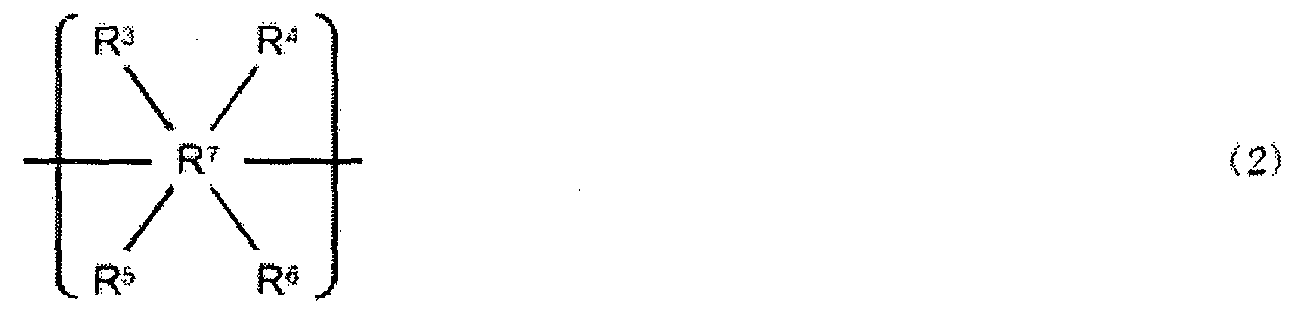
[0045] A substituent which R1 to R7 may each have is a linear or branched alkyl group, aralkyl group, alkoxy group, or hydroxyalkyl group. A substituent obtained by multiply combining those substituents is also permitted, and any such substituent can be introduced to an
arbitrary substitution position at which substitution can occur.
[0046] A condensed polycyclic aromatic compound having high
chemical stability is, for example, the following compound: a condensed polycyclic aromatic compound having an acryloyloxy group or a methacryloyloxy group. Further, the structure other than the acryloyloxy group or methacryloyloxy group of the condensed polycyclic aromatic compound is a structure consisting of a carbon atom and a hydrogen atom, or a structure consisting of a carbon atom, a hydrogen atom, and an oxygen atom. In addition, the condensed polycyclic aromatic compound has features in that the structure other than the acryloyloxy group or methacryloyloxy group of the condensed polycyclic aromatic compound is a structure which includes a conjugate structure containing 24 or more sp2 carbon atoms, and the conjugate structure includes a condensed polycyclic structure containing 12 or more sp2 carbon atoms.
[0047] An sp3 carbon atom may be caused to exist at a moderate ratio in the hole transporting substance of the present invention by appropriately selecting the substituent.
[0048] Compound examples of the hole transporting substance of the present invention are shown below; provided that the present invention is not limited thereto. The reactive functional groups of the following Exemplified
Compounds No. 1 to No . 182 may each be substituted with any one of the reactive functional groups described above. Similarly, the substituents thereof may each be substituted with any one of the substituents described above.
No. 1


No. 3


o. 8
 o. 16
o. 16
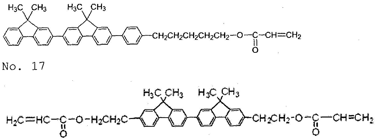 o. li
o. li
 o. 19
o. 19


No. 35

 o. 47
o. 47
 o. 48
o. 48
 o. 49
o. 49
 o. 51
o. 51
 o. 52
o. 52
 o. 53
o. 53

No. 54
 o. 55
o. 55


No. 59

No. 60

No. 61
 o. 63
o. 63

No. 68
 o. 69
o. 69
 o. 70
o. 70
 o. 71
o. 71


No. 76

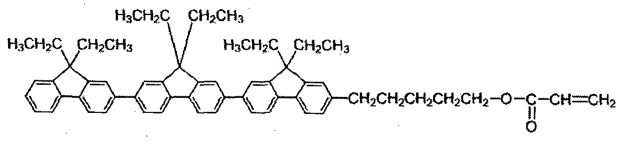


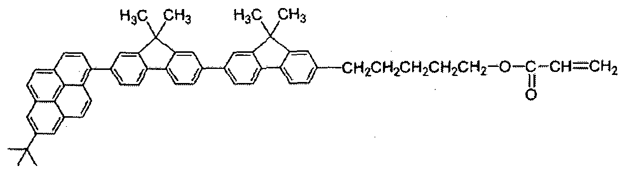
o. 89
 o. 91
o. 91
 o. 92
o. 92
 o. 93
o. 93
 o. 94
o. 94
 o. 95
o. 95


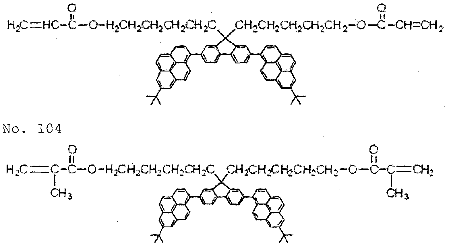


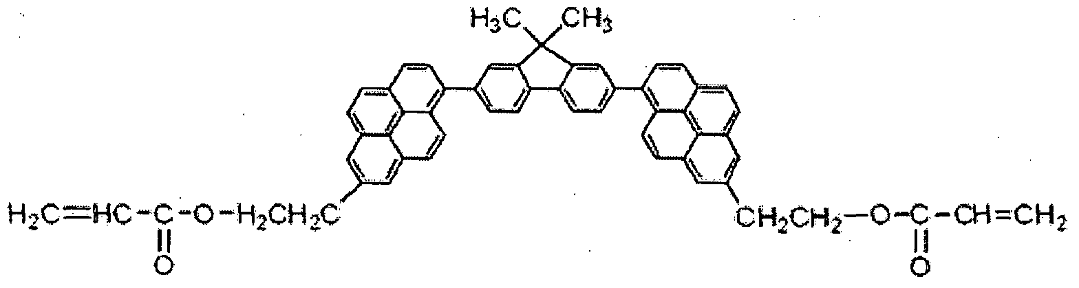


No. 112

o. 113
 o. 114
 o. 115


o. 129

o. 131


o. 135
 o. 136
 o. 137


No. 141


o. 146


No. 158
 No. 163


[0049] A representative synthesis example of the hole
transporting substance to be used in the present invention is described below.
[0050] Exemplified Compound No. 99 shown above was synthesized by a reaction represented by the following reaction formula (1) . 8 Parts of a dihydroxy compound shown in the formula, 90 parts of tetrahydrofuran, and 3.6 parts of triethylamine were loaded into a three-necked flask, and the mixture wad dissolved, followed by the cooling of the mixture with ice water. Next, 2.7 parts of acryloyl chloride were slowly dropped under cooling at 5°C or less while attention was paid to a temperature increase. After the completion of the dropping, the temperature of the reaction mixture was gradually increased until an internal temperature became 50 °C, and the reaction was continued for 30 minutes.
] After the completion of the reaction, 80 parts of a 10% aqueous solution of sodium hydroxide were added to the reaction mixture. 80 Parts of ethyl acetate were loaded into the mixture and an organic phase was separated, followed by the extraction of a product.
The extraction operation was further performed with 80 parts of ethyl acetate twice. The resultant organic phase was subjected to a washing operation with 80 parts of pure water about three times. The washing was performed until the pH of an aqueous phase became about 7. The resultant organic phase was dehydrated with anhydrous magnesium sulfate and magnesium sulfate was removed by filtration. After that, the organic phase was concentrated to provide a crude product.
] An impurity was removed from the resultant crude product by silica gel column chromatography. Further, the resultant was recrystallized with a mixed solvent of 20 parts of ethyl acetate and 20 parts of n-hexane, and was filtered and dried. Thus, the target
diacrylated hole transporting substance was purified (yield=6.8 parts, percent yield=74.9% ) .

] The surface layer of the present invention can contain a polymerized product of a composition containing: the hole transporting substance having a reactive
functional group of the present invention; and a compound having a reactive functional group and free of a structure having hole transportability. The
mechanical strength of the resultant polymerized product can be additionally improved. It is more preferred that: the hole transporting substance of the
present invention has one or more reactive functional groups; and the compound free of a structure having hole transportability has two or more reactive
functional groups.
[0054] he reactive functional group of the compound having a reactive functional group and free of a structure having hole transportability may be the above-mentioned reactive functional group. The reactive functional group is preferably a radically polymerizable
functional group such as a styryl group, a vinyl group, an acryloyloxy group, or a methacryloyloxy group. The reactive functional group is more preferably the following radically polymerizable reactive group: an acryloyloxy group or a methacryloyloxy group.
[0055] The term "monofunctional" representing the number of functional groups described below means that a compound has one reactive functional group.
[0056] Examples of the compound having a reactive functional group and free of a structure having hole
transportability include the following compounds. The examples described below each have an acryloyloxy group as a reactive functional group.
[0057]As a monofunctional polymerizable monomer, there are given, for example, ethyl acrylate, n-propyl acrylate, n-butyl acrylate, isobutyl acrylate, 2-ethylhexyl acrylate, 2-hydroxyethyl acrylate, tetrahydrofurfuryl acrylate, benzyl acrylate, cyclohexyl acrylate, ethoxy- diethylene glycol acrylate, isoamyl acrylate, lauryl acrylate, stearyl acrylate, phenoxyethyl acrylate, phenoxydiethyleneglycol acrylate, and ethoxylated o- phenylphenol acrylate.
[0058] As a difunctional polymerizable monomer, there are
given, for example, 1, -butanediol acrylate, 1,5- pentanediol diacrylate, 3-methyl-l , 5-pentanediol diacrylate, 1, 6-hexanediol acrylate, 1 , 9-nonanediol diacrylate, 1 , 10-decanediol diacrylate, triethylene
glycol diacrylate, neopentyl glycol diacrylate, and tricyclodecanedimethanol diacrylate .
[0059] As a trifunctional polymerizable monomer, there are
given, for example, trimethylolpropane triacrylate, pentaerythritol triacrylate, and ethoxylated
isocyanuric acid triacrylate.
[0060] As a tetrafunctional polymerizable monomer, there are given, for example, pentaerythritol tetraacrylate and dimethylolpropane tetraacrylate.
[0061] As a hexafunctional polymerizable monomer, there is given, for example, dipentaerythritol hexaacrylate .
[0062] Although acrylate monomers are exemplified as described above, a compound having a reactive functional group synthesized by substituting an acryloyloxy group with a methacryloyloxy group or any other reactive functional group may be used as reguired.
[0063] he molecular weight of the compound having a reactive functional group and free of a structure having hole transportability is preferably 100 or more and 1,000 or less.
[ 0064 ] Inorganic fine particles whose surfaces are treated
with a compound having a chain polymerizable functional group may be incorporated into the surface layer from the viewpoint of the wear resistance. A silane
compound having not only the chain polymerizable functional group but also a halogen atom, an alkoxy group, an acyloxy group, an aminooxy group, or the like in a molecule is used as the compound having the chain polymerizable functional group. Silyl group reacts with the inorganic fine particle, and the chain
polymerizable functional group undergoes a
polymerization reaction with the hole transporting substance of the present invention to be strongly stuck into the surface layer, whereby the wear resistance can be improved. Of such groups, an alkoxysilane group is preferred.
[0065] Examples of the chain polymerizable functional group include: radically polymerizable functional groups such as a vinyl group, an acryloyl group, and a methacryloyl group; and cationically polymerizable functional groups such as an epoxy group and an oxetane group. Of the chain polymerizable functional groups, an acryloyl group or a methacryloyl group is preferred. Examples of a compound preferred as the compound having the chain polymerizable functional group are shown below.
One kind of these silane compounds may be used, or two or more kinds thereof may be used as a mixture.
CH2=CHSi (OCH3) 3
CH2=CHCOO (CH2)2Si (CH3) (OCH3)2
CH2=CHCOO (CH2) 2Si (OCH3) 3
CH2=C (CH3) COO (CH2) 2Si (CH3) (OCH3) 2
CH2=C (CH3) COO (CH2) 2Si (OCH3) 3
CH2=CHCOO (CH2) 3Si (CH3) (0CH3)2
CH2=CHCOO (CH2) 3Si (OCH3) 3
CH2=C (CH3) COO (CH2) 3Si (CH3) (OCH3) 2
CH2=C (CH3) COO (CH2 ) 3Si (0CH3) 3
CH2=CHCOO (CH2) 3Si (CH3) Cl2
CH2=CHCOO (CH2) 3Si (OC2H5) 3
CH2=CHCOO(CH2)3Si (CH3) (ONHCH3)2
[0066]As the inorganic fine particles, there may be used
particles including at least one kind selected from the group consisting of alumina, silica, tin oxide and titanium oxide.
[0067] he surface layer can be formed by: forming a coat of a surface-layer coating solution containing the hole transporting substance of the present invention; and drying and/or curing the coat.
[0068] As a solvent to be used for the surface-layer coating solution, there may be used, for example, an alcohol- based solvent, a sulfoxide-based solvent, a ketone- based solvent, an ether-based solvent, an ester-based solvent, an aliphatic halogenated hydrocarbon-based
solvent, or an aromatic hydrocarbon-based solvent.
[0069] hen the surface layer is a protective layer, the
thickness of the surface layer is preferably 0.1 pm or more and 15 μπι or less. In addition, when the surface layer is a charge transporting layer, the thickness is preferably 5 pm or more and 40 pm or less.
[0070] A method of curing the coat of the surface-layer
coating solution . (polymerizing the hole transporting substance of the present invention) is, for example, a method involving polymerizing the substance with heat, light (such as UV light) , or a radiation (such as an electron beam) . Of those, a radiation is preferred, and an electron beam is more preferred out of the radiations.
[0071] The substance is preferably polymerized with an
electron beam because an extremely denseness (high- density) three-dimensional network structure is
obtained and the wear resistance improves. In addition, productivity improves because the polymerization
reaction is efficiently performed within a short time period. An accelerator to be used when the substance is irradiated with an electron beam is, for example, a scanning-, electrocurtain- , broad beam-, pulse-, or laminar-type accelerator.
[0072] When an electron beam is used, the acceleration voltage of the electron beam is preferably 120 kV or less from the following viewpoint: the deterioration of the material characteristics due to the electron beam can be suppressed without the impairment of polymerization efficiency. In addition, an electron beam absorbed dose on the surface of the coat of the surface-layer coating solution is preferably 5 kGy or more and 50 kGy or less, more preferably 1 kGy or more and 10 kGy or less.
[0073] In addition, when the hole transporting substance of
the present invention is polymerized with an electron
beam, the following is preferred for the purpose of the suppression of the polymerization-inhibiting action of oxygen: after having been irradiated with the electron beam in an inert gas atmosphere, the hole transporting substance is heated in the inert gas atmosphere.
Examples of the inert gas include nitrogen, argon, and helium.
[0074] ext, the entire construction of the
electrophotographic photosensitive member of the present invention is described.
[0075] Electrophotographic photosensitive member>
[0076] A preferred construction of the electrophotographic photosensitive member in the present invention is a construction in which a charge generating layer and a hole transporting layer are laminated in the stated order on a support. As required, a conductive layer or an undercoat layer may be provided between the charge generating layer and the support, and a protective layer may be provided on the hole transporting layer. It should be noted that in the present invention, the charge generating layer and the hole transporting layer are collectively referred to as "photosensitive layer".
[0077] The hole transporting substance of the present
invention is incorporated into a surface layer. The term "surface layer" as used in the present invention refers to the protective layer when the protective layer is provided in the electrophotographic
photosensitive member, and refers to the hole
transporting layer when the protective layer is not provided.
[0078] In addition, the photosensitive layer may be formed of a single-layer photosensitive layer containing a charge generating substance and the hole transporting
substance.
[0079] <Support>
[0080] A conductive support formed of a material having
electro-conductivity is preferred as the support to be used in the present invention. Examples of the
material for the support include: metals and alloys such as iron, copper, gold, silver, aluminum, zinc, titanium, lead, nickel, tin, antimony, indium, chromium, an aluminum alloy, and stainless steel. In addition, there may be used a support made of a metal or support made of a resin having a coat formed by depositing aluminum, an aluminum alloy, an indium oxide-tin oxide alloy, or the like through vacuum evaporation. In addition, there may also be used a support obtained by impregnating a plastic or paper with conductive
particles such as carbon black, tin oxide particles, titanium oxide particles, or silver particles, or a support containing a conductive resin. The shape of the support is, for example, a cylinder-like, belt-like, sheet-like, or plate-like shape, and is most generally a cylinder-like shape.
[0081] he surface of the support may be subjected to a
cutting treatment, a surface roughening treatment, an alumite treatment., or the like from the viewpoints of, for example, the suppression of an interference fringe due to the scattering of laser light, the alleviation of a defect in the surface of the support, and an improvement in conductivity of the support.
[0082] A conductive layer may be provided between the support and the undercoat layer or charge generating layer to be described later for the purpose of the suppression of an interference fringe due to the scattering of laser light or the like, resistance control, or the covering of a flaw of the support.
[0083] he conductive layer can be formed by: applying a
conductive-layer coating solution obtained by
subjecting carbon black, a conductive pigment, a
resistance regulating pigment, or the like to a
dispersion treatment together with a binder resin; and
drying the resultant coat. A compound that undergoes curing polymerization through heating, UV irradiation, radiation irradiation, or the like may be added to the conductive-layer coating solution. The surface of the conductive layer obtained by dispersing the conductive pigment or the resistance regulating pigment tends to be roughened.
[0084] The thickness of the conductive layer is preferably 0.1 μπι or more and 50 μπι or less, more preferably 0.5 μπι or more and 40 ym or less, still more preferably 1 pm or more and 30 μιτι or less.
[0085] Examples of the binder resin to be used for the
conductive layer include: a polymer and copolymer of a vinyl compound such as styrene, vinyl acetate, vinyl chloride, an acrylic acid ester, a methacrylic acid ester, vinylidene fluoride, or trifluoroethylene; and a polyvinyl alcohol resin, a polyvinyl acetal resin, a polycarbonate resin, a polyester resin, a polysulfone resin, a polyphenylene oxide resin, a polyurethane resin, a cellulose resin, a phenol resin, a melamine resin, a silicone resin, an epoxy resin, and an
isocyanate resin.
[0086] Examples of the conductive pigment and the resistance regulating pigment include particles of a metal (alloy) such as aluminum, zinc, copper, chromium, nickel, silver, or stainless steel, and plastic particles each having the metal deposited on its surface. In addition, there may be used particles of a metal oxide such as zinc oxide, titanium oxide, tin oxide, antimony oxide, indium oxide, bismuth oxide, tin-doped indium oxide, or antimony- or tantalum-doped tin oxide. One kind of those pigments may be used alone or two or more kinds thereof may be used in combination.
[0087] The undercoat layer (intermediate layer) may be
provided between the support or the conductive layer and the charge generating layer for the purposes of,
for example, an improvement in adhesiveness of the charge generating layer, an improvement in property by which a hole is injected from the support, and the protection of the charge generating layer from an electrical breakdown.
[0088] The undercoat layer can be formed by: applying an
undercoat-layer coating solution obtained by dissolving a binder resin in a solvent; and drying the resultant coat .
[0089] Examples of the binder resin to be used for the
undercoat layer include a polyvinyl alcohol resin, poly-N-vinylimidazole, a polyethylene oxide resin, ethyl cellulose, an ethylene-acrylic acid copolymer, casein, a polyamide resin, an N-methoxymethylated 6- nylon resin, a copolymerized nylon resin, a phenol resin, a polyurethane resin, an epoxy resin, an acrylic resin, a melamine resin, and a polyester resin.
[0090] Metal oxide particles may further be incorporated into the undercoat layer. An example of the metal oxide particles is particles containing titanium oxide, zinc oxide, tin oxide, zirconium oxide, or aluminum oxide. In addition, the metal oxide particles may be metal oxide particles each having a surface treated with a surface treatment agent such as a silane coupling agent.
[0091] The thickness of the undercoat layer is preferably 0.05 μπι or more and 30 μπι or less, more preferably 1 μπι or more and 25 μπ\ or less. Organic resin fine particles or a leveling agent may further be incorporated into the undercoat layer.
[0092] Next, the charge generating layer is described. The
charge generating layer can be formed by: applying a charge-generating-layer coating solution obtained by subjecting a charge generating substance to a
dispersion treatment together with a binder resin and a solvent to form a coat; and drying the resultant coat. Alternatively, the charge generating layer may be a
deposited film of the charge generating substance.
[0093] Examples of the charge generating substance to be used for the charge generating layer include azo pigments, phthalocyanine pigments, indigo pigments, perylene pigments, polycyclic quinone pigments, squarylium dyes, pyrylium salts, thiapyrylium salts, triphenylmethane dyes, quinacridone pigments, azulenium salt pigments, cyanine dyestuffs, anthanthrone pigments, pyranthrone pigments, xanthene dyes, quinone imine dyes, and styryl dyes. Only one kind of those charge generating
substances may be used or two or more kinds thereof may be used. Of those charge generating substances, from the viewpoint of sensitivity, phthalocyanine pigments or azo pigments are preferred, and phthalocyanine pigments are particularly more preferred.
[0094] Of the phthalocyanine pigments, in particular,
oxytitanium phthalocyanines, chlorogallium
phthalocyanines, or hydroxygallium phthalocyanines exhibit excellent charge generation efficiency.
Further, of the hydroxygallium phthalocyanines, a hydroxygallium phthalocyanine crystal of a crystal form having peaks at Bragg angles 2Θ in CuKa characteristic X-ray diffraction of 7.4°±0.3° and 28.2°±0.3° is more preferred from the viewpoint of sensitivity.
[0095] Examples of the binder resin to be used for the charge generating layer include: polymers of vinyl compounds such as styrene, vinyl acetate, vinyl chloride, an acrylic acid ester, a methacrylic acid ester,
vinylidene fluoride, and trifluoroethylene; and a polyvinyl alcohol resin, a polyvinyl acetal resin, a polycarbonate resin, a polyester resin, a polysulfone resin, a polyphenylene oxide resin, a polyurethane resin, a cellulose resin, a phenol resin, a melamine resin, a silicone resin, and an epoxy resin.
[0096] he mass ratio between the charge generating substance and the binder resin preferably falls within the range
of from 1:0.3 to 1:4.
[0097] The thickness of the charge generating layer is
preferably 0.05 pm or more and 1 pm or less, more preferably 0.1 pm or more and 0.5 pm or less.
[0098] Next, the hole transporting layer is described. When the hole transporting layer is the surface layer, the surface layer contains the polymerized product of the hole transporting substance of the present invention as described above.
[0099] On the other hand, when the protective layer is
provided on the hole transporting layer, the hole transporting layer can be formed by: forming a coat of a hole-transporting-layer coating solution obtained by mixing the hole transporting substance and a binder resin in a solvent; and drying the coat. Hereinafter, the hole transporting substance and binder resin to be used in the hole transporting layer are described.
[0100] Examples of the hole transporting substance include a carbazole compound, a hydrazone compound, an N,N- dialkylaniline compound, a diphenylamine compound, a triphenylamine compound, a triphenylmethane compound, a pyrazoline compound, a styryl compound, and a stilbene compound .
[0101] Examples of the binder resin include an acrylic acid ester, a methacrylic acid ester, a polyvinyl alcohol resin, a polyvinyl acetal resin, a polycarbonate resin, and a polyester resin. In addition, there may be used a curable resin such as a curable phenol resin, a curable urethane resin, a curable melamine resin, a curable epoxy resin, a curable acrylic resin, or a curable methacrylic resin.
[ 0102 ] Examples of the solvent to be used for the hole- transporting-layer coating solution include an alcohol- based solvent, a sulfoxide-based solvent, a ketone- based solvent, an ether-based solvent, an ester-based solvent, an aliphatic halogenated hydrocarbon-based
solvent,, and an aromatic hydrocarbon-based solvent.
[0103] The thickness of the hole transporting layer is
preferably 1 μτη or more and 100 μπι or less, more
preferably 3 μτ or more and 50 μτ or less, still more preferably 5 μπι or more and 40 μτη or less.
[0104] Various additives can be added to each layer of the
electrophotographic photosensitive member of the
present invention. Specific examples thereof include an organic pigment, an organic dye, a coat surface adjustor, an electron transport agent, an oil, a wax, an antioxidant, a light absorber, a polymerization initiator, a radical deactivator, organic resin fine particles, and inorganic particles.
[0105] The surface of each layer of the electrophotographic
photosensitive member may be subjected to surface processing with, for example, a polishing sheet, a shape transfer mold member, glass beads, or zirconia beads. In addition, unevenness may be formed in the surface with the constituent material for the coating solutio .
[0106] In the application of the coating solution for each of the layers, there may be used any known application method such as a dip coating method, a spray coating method, a circular amount-regulating type (ring)
coating method, a spin coating method, a roller coating method, a Mayer bar coating method, or a blade coating method .
[0107] Next, a process cartridge including the
electrophotographic photosensitive member and an image forming process of the present invention are described.
[0108] FIG. 1 illustrates an example of the construction of
the process cartridge of the present invention. In FIG. 1, a cylindrical electrophotographic photosensitive member 1 is rotationally driven in an arrow direction at a predetermined peripheral speed. The peripheral surface of the electrophotographic photosensitive
member 1 to be rotationally driven is uniformly charged to a predetermined positive or negative potential by a charging device 2. Next, the charged peripheral surface of the electrophotographic photosensitive member 1 receives exposure light (image exposure light) 3 output from an exposing device (not shown) such as slit exposure or laser beam scanning exposure. Thus, electrostatic latent images corresponding to a target image are sequentially formed on the peripheral surface of the electrophotographic photosensitive member 1. Any one of a voltage obtained by superimposing an AC component on a DC component and a voltage consisting of the DC component may be used as a voltage to be applied to the charging device (such as a charging roller) 2.
[0109] The electrostatic latent images formed on the
peripheral surface of the electrophotographic
photosensitive member 1 are developed with toner in the developer of a developing device 4 to be turned into toner images. Next, the toner images formed and supported on the peripheral surface of the
electrophotographic photosensitive member 1 are
sequentially transferred onto a transfer material (such as paper or an intermediate transfer member) 6 by a transfer bias from a transferring device (such as a transfer roller) 5. The transfer material 6 is fed in synchronization with the rotation of the
electrophotographic photosensitive member 1.
[0110] The surface of the electrophotographic photosensitive member 1 after the transfer of the toner images is subjected to an electricity eliminating treatment with pre-exposure light 7 from a pre-exposing device (not shown) , and is then cleaned through the removal of transfer residual toner by a cleaning device 8. Thus, the electrophotographic photosensitive member 1 is repeatedly used in image formation. It should be noted that the pre-exposing device may be operated before or
after the cleaning step, and the pre-exposing device is not necessarily needed.
[0111] he electrophotographic photosensitive member 1 may be mounted onto an electrophotographic apparatus such as a copying machine or a laser beam printer. In addition, a process cartridge 9 formed by storing two or more of the components such as the electrophotographic
photosensitive member 1, the charging device 2, the developing device 4, and the cleaning device 8 in a container and integrally supporting the components can be detachably mountable to the main body of the
electrophotographic apparatus. In FIG. 1, the
electrophotographic photosensitive member 1, the charging device 2, the developing device 4, and the cleaning device 8 are integrally supported to form a cartridge. Then, the cartridge is used as a process cartridge 9 detachably mountable to the main body of the electrophotographic apparatus.
[0112] ext, an electrophotographic apparatus including the electrophotographic photosensitive member of the present invention is described.
[0113] FIG. 2 illustrates an example of the construction of the electrophotographic apparatus of the present invention. A process cartridge 17 for a yellow color, a process cartridge 18 for a magenta color, a process cartridge 19 for a cyan color, and a process cartridge 20 for a black color, corresponding to the respective colors, i.e., the yellow color, the magenta color, the cyan color, and the black color, are placed side by side along an intermediate transfer member 10. As illustrated in FIG. 2, the diameter and constituent material of the electrophotographic photosensitive member, a developer, a charging system, and any other device do not necessarily need to be standardized for■ the respective colors. For example, in the
electrophotographic apparatus of FIG. 2, the diameter
of the electrophotographic photosensitive member for the black color is larger than that for any other color (yellow, magenta, or cyan) . In addition, a system involving using corona discharge is adopted as a charging system for the black color while a system involving applying a voltage obtained by superimposing an AC component on a DC. component is adopted as a charging system for any other color.
[0114] hen an image forming operation starts, the toner
images of the respective colors are sequentially superimposed on the intermediate transfer member 10 according to the image forming process. In tandem with the foregoing, transfer paper 11 is sent from a sheet feeding tray 13 along a sheet feeding path 12, and is then fed to a secondary transferring device 14 in timing with the rotation operation of the intermediate transfer member. The toner images on the intermediate transfer member 10 are transferred onto the transfer paper 11 by a transfer bias from the secondary
transferring device 14. The toner images transferred onto the transfer paper 11 are conveyed along the sheet feeding path 12, fixed on the transfer paper by a fixing device 15, and then discharged from a sheet discharging portion 16.
[0115] Hereinafter, the present invention is described in more detail by way of specific examples. It should be noted that the term "part(s)" in the examples refers to
"part(s) by mass". In addition, an electrophotographic photosensitive member is hereinafter sometimes simply referred to as "photosensitive member".
[0116] <Production of electrophotographic photosensitive
member>
[0117] Example photosensitive member 1
[0118] A cylindrical aluminum cylinder having an outer
diameter of 30 mm, a length of 357.5 mm, and a
thickness of 0.7 mm was used as a support (electro-
conductive support) .
[0119] ext, 10 parts of zinc oxide particles (specific
surface area: 19 m2/g, powder resistivity: 4.7*106 Ω-cm) were mixed with 50 parts of toluene by stirring, and 0.08 part of a silane coupling agent was added to the mixture, followed by stirring for 6 hours. After that, toluene was removed by distillation under reduced pressure and the residue was dried by heating at 130 °C for 6 hours to provide surface-treated zinc oxide particles. KBM602 (compound name: N-2- (aminoethyl ) -3- aminopropylmethyldimethoxysilane) manufactured by Shin- Etsu Chemical Co., Ltd. was used as the silane coupling agent.
[0120] ext, 15 parts of a polyvinyl butyral resin (weight- average molecular weight: 40,000, trade name: BM-1, manufactured by SEKISUI CHEMICAL CO., LTD.) and 15 parts of a blocked isocyanate (trade name: Sumidur 3175, manufactured by Sumika Bayer Urethane Co., Ltd.) were dissolved in a mixed solution of 73.5 parts of methyl ethyl ketone and 73.5 parts of 1-butanol. 80.8 Parts of the surface-treated zinc oxide particles and 0.8 part of 2, 3, -trihydroxybenzophenone (manufactured by Tokyo Chemical Industry Co., Ltd.) were added to the solution, and the mixture was dispersed with a sand mill apparatus using glass beads each having a diameter of 0.8 mm under an atmosphere having a temperature of 23±3°C for 3 hours. After the dispersion, 0.01 part of silicone oil (trade name: SH28PA, manufactured by Dow Corning Toray Co., Ltd.) and 5.6 parts of crosslinked polymethyl methacrylate (PMMA) particles (trade name: TECHPOLYMER SSX-102, manufactured by SEKISUI PLASTICS CO., Ltd., average primary particle diameter: 2.5 μιη) were added to the resultant, and the resultant was stirred to prepare an undercoat-layer coating solution.
[0121] he undercoat-layer coating solution was applied onto the support by dipping to form a coat, and the
resultant coat was dried for 40 minutes at 160°C to form an undercoat layer having a thickness of 18 ym.
[0122] Next, a hydroxygallium phthalocyanine crystal (charge generating substance) of a crystal form having peaks at Bragg angles 2Θ±0.2° in CuKa characteristic X-ray diffraction of 7.4° and 28.2° was prepared. 2 Parts of the hydroxygallium phthalocyanine crystal, 0.02 part of a calixarene compound represented by the following structural formula (A), 1 part of polyvinyl butyral (trade name: S-LEC BX-1, manufactured by SEKISUI
CHEMICAL CO., LTD.), and 60 parts of cyclohexanone were loaded into a sand mill using glass beads each having a diameter of 1 mm, followed by a dispersion treatment for 4 hours. After that, 70 parts of ethyl acetate were added to the resultant to prepare a charge- generating-layer coating solution. The charge- generating-layer coating solution was applied onto the undercoat layer by dipping, and the resultant coat was dried for 15 minutes at 80°C to form a charge
generating layer having a thickness of 0.17 μπι.

[0123] Next, 6 parts of a compound represented by the
following structural formula (B) , 3 parts of a compound represented by the following structural formula (C) , 1 part of a compound represented by the following
structural formula (D), and 10 parts of a bisphenol Z-
type polycarbonate resin (trade ame: Iupilon Z400, manufactured by Mitsubishi Engineering-Plastics
Corporation) were dissolved in a mixed solvent of 60 parts of monochlorobenzene and 20 parts of
dimethoxymethane to prepare a hole-transporting-layer coating solution. The hole-transporting-layer coating solution was applied onto the charge generating layer by dipping, and the resultant coat was dried for 50 minutes at 100°C to form a hole transporting layer having a thickness of 18 μτη.

[0124] ext, 3 parts of the compound represented by
Exemplified Compound No. 52 were dissolved in 5 parts of l-methoxy-2-propanol and 2 parts of ethylene glycol dimethyl ether to prepare a protective-layer coating solution. The protective-layer coating solution was applied onto the hole transporting layer by dipping, and the resultant coat was dried for 10 minutes at 50°C, followed by a polymerization curing treatment through electron beam irradiation and heating under the
following conditions.
[0125] In an atmosphere having an oxygen concentration of 100 ppm or less, the electron beam irradiation was
performed with an electron beam irradiation apparatus under the conditions of an irradiation distance of 30
mm, an acceleration voltage of 70 kV, a beam current of 10 mA, and an irradiation time of 6.4 seconds while the aluminum cylinder was rotated at a speed of 300 rpm.
After the electron beam irradiation, the temperature of the surface of the protective layer coat was caused to reach 130°C over 20 seconds with an induction heating apparatus. Next, the aluminum cylinder was taken out to the air atmosphere and further heated for 10 minutes at 100°C to form a protective layer having a thickness of 5 μτα .
[0126]An example photosensitive member 1 was produced as
described above.
[ 0127 ] Example photosensitive members 2 to 5
[0128] Electrophotographic photosensitive members were
produced in the same manner as in the example
photosensitive member 1 except that the compound
represented by Exemplified Compound No. 52 was changed to Exemplified Compounds No. 81 (photosensitive member 2), No. 59 (photosensitive member 3), No. 61
(photosensitive member 4), and No. 94 (photosensitive member 5) , respectively.
[0129] Example photosensitive member 6
[0130] An electrophotographic photosensitive member was
produced in the same manner as in the example
photosensitive member 1 except that a protective layer was formed as described below.
[0131] 4 Parts of the compound represented by Exemplified
Compound No. 48 were dissolved in 100 parts of
tetrahydrofuran to prepare a protective-layer coating solution. The protective-layer coating solution was applied onto the hole transporting layer by spraying, and the resultant coat was dried for 10 minutes at 50°C, followed by a polymerization curing treatment through electron beam irradiation and heating under the same conditions as those of the example photosensitive member 1. Next, the aluminum cylinder was taken out to
the air atmosphere and further heated for 10 minutes at 100 °C to form the protective layer having a thickness of 5 μπι.
[0132] Example photosensitive member 7
[0133] An electrophotographic photosensitive member was
produced in the same manner as in the example
photosensitive member 6 except that Exemplified
Compound No. 48 in the example photosensitive member 6 was changed to the compound represented by Exemplified Compound No. 99.
[0134 ] Example photosensitive member 8
[0135] The same aluminum cylinder as that used in the example photosensitive member 1 was used as a. support.
[0136] ext, 60 parts of Ti02 particles coated with oxygen- deficient Sn02 (powder resistivity: 100 Ω·αη, coat with Sn02 (mass ratio): 35%), 36.5 parts of a phenol resin (trade name: PLYOPHEN J-325, manufactured by DIC
Corporation, resin solid content: 60%), and 20 parts of methoxypropanol as a solvent were dispersed with a horizontal sand mill disperser using glass beads each having a diameter of 1 mm.
[0137] The glass beads were removed from the dispersion with a mesh. After that, 1.6 parts of silicone resin
particles (trade name: TOSPEARL 120, manufactured by Momentive Performance Materials Inc., average particle diameter: 2 μπι) and 0.008 part of silicone oil (SH28PA) were added to the dispersion, and the resultant was stirred to prepare a conductive-layer coating solution. The average particle diameter of the Ti02 particles coated with oxygen-deficient Sn02 in the conductive- layer coating solution was 0.35 ym. The conductive- layer coating solution was applied onto the support by dipping to form a coat, and the resultant coat was dried and cured for 30 minutes at 140°C to form a conductive layer having a thickness of 18 μπι.
[0138] ext, 10 parts of a methoxymethylated 6-nylon resin
(trade name: TORESIN EF-30T, manufactured by Nagase ChemteX Corporation) were dissolved in a mixed solvent of 100 parts of methanol and 50 parts of n-butanol to prepare an undercoat-layer coating solution. The undercoat-layer coating solution was applied onto the conductive layer by dipping, and the resultant coat was dried for 30 minutes at 100°C to form an undercoat layer having a thickness of 0.45 μι . Next, a charge generating layer and a hole transporting layer were formed in the stated order in the same manner as in the example photosensitive member 1.
[0139] ext, a protective layer was formed in the same manner as in the example photosensitive member 6 except that Exemplified Compound No. 48 was changed to the compound represented by Exemplified Compound No. 148.
[ 0140] Example photosensitive member 9
[0141] An electrophotographic photosensitive member was
produced in the same manner as in the example
photosensitive member 6 except that Exemplified
Compound No. 48 in the example photosensitive member 6 was changed to the compound represented by Exemplified Compound No. 101.
[0142] The resultant photosensitive member was placed in a pressure-contact shape transferring apparatus of a construction illustrated in FIG. 3 with a mold member as illustrated in FIGS. 4A and 4B. The mold member illustrated in FIGS. 4A and 4B is as follows: the shape of a protruded portion is a dome-type shape having a diameter Xm of 50 μιη and a height H of 3 μπι, and the ratio of the total area of the protruded portions per a predetermined area including 10 or more protruded portions is 15% (hereinafter sometimes simply referred to as "area ratio of the protruded portions of the mold member"). The protective layer of the
electrophotographic photosensitive member was subjected to surface shape processing with the mold member under
the following conditions.
[0143] At the time of the processing, the temperatures of an electrophotographic photosensitive member 21 and a mold member 22 were controlled so that the temperature of the surface of the electrophotographic photosensitive member became 90°C. In FIG. 3, the mold member 22 was moved at a speed of 20 mm/sec in an arrow direction represented by a direction horizontal to the surface of the mold member 22 while the electrophotographic
photosensitive member 21 and a pressure member 23 were pressed against each other in an arrow direction
represented by a direction vertical to the surface of the mold member 22 at a pressure of 2.0 MPa. Thus, depressed portions were formed in the surface of the protective layer while the electrophotographic
photosensitive member 21 was rotated to follow the movement. The depressed portions formed in the surface of the protective layer were observed with a laser microscope (VK-9500 manufactured by KEYENCE
CORPORATION) . As a result., the deepest depth of the depressed portions was 2 pm, the longest diameter of the depressed portions was 50 pm, and the area ratio was 15%. Thus, an example photosensitive member 9 was produced.
[014 ] Example photosensitive member 10
[0145] An electrophotographic photosensitive member was
produced in the same manner as in the example
photosensitive member 6 except that Exemplified
Compound No. 48 in the example photosensitive member 6 was changed to the compound represented by Exemplified Compound No. 114.
[0146] Example photosensitive members 11 to 14
[0147 ] Electrophotographic photosensitive members were
produced in the same manner as in the example
photosensitive member 6 except that Exemplified
Compound No. 48 was changed to Exemplified Compounds No.
117 (photosensitive member 11), No. 122 (photosensitive member 12), No. 126 (photosensitive member 13), and No. 127 (photosensitive member 14), respectively.
[0148] Example photosensitive member 15
[0149] An electrophotographic photosensitive member was
produced in the same manner as in the example
photosensitive member 1 except that a protective layer was formed as described below.
[0150] Parts of the compound represented by Exemplified
Compound No. 158 and 0.01 part of p-toluenesulfonic acid were dissolved in 100 parts of tetrahydrofuran to prepare a protective-layer coating solution. The protective-layer coating solution was applied onto the hole transporting layer by spraying, and the resultant coat was dried and thermally cured for 60 minutes at 150°C to form the protective layer having a thickness of 6 μπι.
[0151] Example photosensitive member 16
[0152] An electrophotographic photosensitive member was
produced in the same manner as in the example
photosensitive member 15 except that Exemplified
Compound No. 158 in the example photosensitive member 15 was changed to the compound represented by
Exemplified Compound No. 167 and the thickness of the protective layer was set to 6 μηα.
[ 0153] Example photosensitive member 17
[0154] An electrophotographic photosensitive member was
produced in the same manner as in the example
photosensitive member 1 except that a protective layer was formed as described below.
[0155] 4 Parts of the compound represented by Exemplified
Compound No. 171 were dissolved in 100 parts of
tetrahydrofuran to prepare a protective-layer coating solution. The protective-layer coating solution was applied onto the hole transporting layer by spraying, and the resultant coat was dried and thermally cured
for 60 minutes at 150°C to form the protective layer having a thickness of 7 m.
[0156] Example photosensitive member 18
[0157] An electrophotographic photosensitive member was
produced in the same manner as in the example
photosensitive member 1 except that a protective layer was formed as described below.
[0158] ext, 1.5 parts of a fluorine atom-containing resin
(trade name: GF400, manufactured by TOAGOSEI CO., LTD.) were dissolved in a mixed solvent of 45 parts of 1- propanol and 45 parts of 1,1,2,2,3,3,4- heptafluorocyclopentane (trade name: ZEORORA H,
manufactured by ZEON CORPORATION). After that, 30 parts of ethylene fluoride resin powder (trade name: LUBRON L-2, manufactured by DAIKIN INDUSTRIES, LTD.) were added to the solution and the resultant was dispersed with a high-pressure disperser (trade name: Microfluidizer M-110EH, manufactured by Microfluidics in the U.S.) to provide an ethylene fluoride resin dispersion .
[0159] 8 Parts of Exemplified Compound No. 18, 8 parts of
Exemplified Compound No. 49, 8 parts of Exemplified Compound No. 68, 1 part of 1-hydroxycyclohexyl phenyl ketone, and 12 parts of the ethylene fluoride resin dispersion were added to a mixed solvent of 30 parts of tetrahydrofuran, 30 parts of 1-propanol, and 40 parts of 1, 1, 2, 2, 3, 3, 4-heptafluorocyclopentane (trade name: ZEORORA H, manufactured by ZEON CORPORATION), and the resultant was stirred to prepare a protective-layer coating solution. The protective-layer coating
solution was applied onto the hole transporting layer by dipping, and the resultant coat was dried for 10 minutes at 45°C, followed by a photocuring treatment under the following conditions.
[0160] Under an atmosphere having an oxygen concentration of
6,000 to 8,000 ppm, photoirradiation was performed with
a metal halide lamp having an output of 160 W/cm under the conditions of an irradiation distance of 100 mm, an irradiation intensity of 600 mW/cm2, and an irradiation time of 2 minutes while the aluminum cylinder having applied thereto the coat of the protective-layer coating solution was rotated at a speed of 100 rpm. After the photoirradiation, the resultant was heated for 30 minutes at 135°C to form the protective layer having a thickness of 4 μιη.
[0161 ] Example photosensitive member 19
[0162] An electrophotographic photosensitive member was
produced in the same manner as in the example
photosensitive member 1 except that a protective layer was formed as described below.
[0163] 10 Parts of the compound represented by Exemplified Compound No. 14, 10 parts of trimethylolpropane
triacrylate, 2 parts of 1-hydroxycyclohexyl phenyl ketone as a photopolymerization initiator, 2 parts of 2,2-bis (4, -di-t-butylperoxycyclohexyl) propane, and 580 parts of tetrahydrofuran were mixed to prepare a protective-layer coating solution. The protective- layer coating solution was applied onto the hole transporting layer by spraying, and the resultant coat was dried for 10 minutes at 45°C, followed by
photoirradiation by the same method as that of the example photosensitive member 18. After that, the resultant was subjected to a heat treatment to form the protective layer having a thickness of 4 μιτι.
[0164 ] Example photosensitive member 20
[0165] An electrophotographic photosensitive member was
produced in the same manner as in the example
photosensitive member 1 except that a protective layer was formed as described below.
[0166] 10 Parts of the compound represented by Exemplified Compound No. 30, 10 parts of trimethylolpropane
triacrylate, and 570 parts of tetrahydrofuran were
mixed to prepare a protective-layer coating solution. The protective-layer coating solution was applied onto the hole transporting layer by spraying, and the resultant coat was irradiated with an electron beam by the same method as that of the example photosensitive member 1. After that, the resultant was subjected to a heat treatment to form the protective layer having a thickness of 4 μπι.
[ 0167 ] Example photosensitive member 21
[0168] An electrophotographic photosensitive member was
produced in the same manner as in the example
photosensitive member 1 except that a protective layer was formed as described below.
[0169] 12 Parts of the compound represented by Exemplified Compound No. 45, 8 parts of ditrimethylolpropane tetraacrylate, and 570 parts of tetrahydrofuran were mixed to prepare a protective-layer coating solution. The protective-layer coating solution was applied onto the hole transporting layer by spraying, and the resultant coat was irradiated with an electron beam by the same method as that of the example photosensitive member 1. After that, the resultant was subjected to a heat treatment to form the protective layer having a thickness of 4 μπι.
[0170] Example photosensitive member 22
[0171] An electrophotographic photosensitive member was
produced in the same manner as in the example
photosensitive member 1 except that a protective layer was formed as described below.
[0172] 10 Parts of the compound represented by Exemplified
Compound No. 50, 10 parts of 1 , 6-hexanediol diacrylate, and 570 parts of tetrahydrofuran were mixed to prepare a protective-layer coating solution. The protective- layer coating solution was applied onto the hole transporting layer by spraying, and the resultant coat was irradiated with an electron beam by the same method
as that of the example photosensitive member 1. After that, the resultant was subjected to a heat treatment to form the protective layer having a thickness of 4 μπι.
[0173] Example photosensitive member 23
[0174] An electrophotographic photosensitive member was
produced in the same manner as in the example
photosensitive member 1 except that a protective layer was formed as described below.
[0175] 100 Parts of alumina particles having a number-average particle diameter of 20 nm, 30 parts of a compound having a chain polymerizable functional group
represented by a rational formula
"CH2=CHCOO(CH2)2Si (CH3) (OCH3)2", and 1, 000 parts of methyl ethyl ketone were loaded into a wet sand mill containing alumina beads, and were mixed at 30 °C for 6 hours. After that, the methyl ethyl ketone and the alumina beads were separated by filtration, and the resultant was dried at 60°C to provide surface-treated alumina particles.
[0176] 2 Parts of Exemplified Compound No. 101, 2 parts of
trimethylolpropane triacrylate, 0.6 part of 1- hydroxycyclohexyl phenyl ketone, and 1 part of the surface-treated alumina particles were dissolved in 100 parts of tetrahydrofuran to prepare a protective-layer coating solution. The protective-layer coating
solution was applied onto the hole transporting layer by spraying, and the resultant coat was dried for 10 minutes at 45°C, followed by a photocuring treatment in the same manner as in the example photosensitive member 18. Thus, the protective layer having a thickness of 4 μιη was formed.
[0177] Example photosensitive member 24
[0178] Surface-treated silica particles were obtained in the same manner as in the example photosensitive member 23 except that the alumina particles having a number- average particle diameter of 20 nm in the example
photosensitive member 23 were changed to silica particles having a number-average particle diameter, of 20 nra. A protective layer was formed and an
electrophotographic photosensitive member was produced in the same manner as in the example photosensitive member 18.
[0179] Example photosensitive member 25
[0180] Surface-treated tin oxide particles were obtained in the same manner as in the example photosensitive member 23 except that the alumina particles having a number- average particle diameter of 20 nm in the example photosensitive member 23 were changed to tin oxide particles having a number-average particle diameter of 20 nm.
[0181] 2 Parts of Exemplified Compound No. 101, 1 part of
trimethylolpropane triacrylate, 1 part of a compound represented by the following structural formula (12) , 0.6 part of 1-hydroxycyclohexyl phenyl ketone, and 1 part of the surface-treated tin oxide particles were dissolved in 100 parts of tetrahydrofuran to prepare a protective-layer coating solution. The protective- layer coating solution was applied onto the hole transporting layer by spraying, and the resultant coat was dried for 10 minutes at 45°C, followed by a
photocuring treatment in the same manner as in the example photosensitive member 18. Thus, a protective layer having a thickness of 4 m was formed and an electrophotographic photosensitive member was produced.

[0182] Example photosensitive member 26
[0183]An electrophotographic photosensitive member was
produced in the same manner as in the example
photosensitive member 1 except that a protective layer was formed as described below.
[0184] Next, 3.5 parts of Exemplified Compound No. 132, 0.1 part of 1-hydroxycyclohexyl phenyl ketone, and 0.3 part of a-alumina particles (trade name: SUMICORANDOM AA-3, manufactured by Sumitomo Chemical Co., Ltd.) were added to 100 parts of tetrahydrof ran, and the resultant was stirred to prepare a protective-layer coating solution. The protective-layer coating solution was applied onto the hole transporting layer by spraying, and the resultant coat was dried for 10 minutes at 45°C, followed by a photocuring treatment in the same manner as in the example photosensitive member 18. Thus, the protective layer having a thickness of 4 μπν was formed.
[0185] Example photosensitive member 27
[0186] An example photosensitive member 27 was produced in the same manner as in the example photosensitive member 1 except that a cylindrical aluminum cylinder having an outer diameter of 84.0 mm, a length of 370 mm, and a thickness of 3.0 mm was used as a support.
[0187] Comparative example photosensitive member 1
[0188] An electrophotographic photosensitive member was
produced in the same manner as in the example
photosensitive member 1 except that a protective layer
was formed as described below.
[0189] 4 Parts of a compound represented by the following structural formula (13) were dissolved in 100 parts of tetrahydrofuran to prepare a protective-layer coating solution. The protective-layer coating solution was applied onto the hole transporting layer by spraying, and the resultant coat was dried and thermally cured for 60 minutes at 150 °C to form the protective layer having a thickness of 7 pm.

[0190] Comparative example photosensitive member 2
[0191] An electrophotographic photosensitive member was
produced in the same manner as in the example
photosensitive member 1 except that a protective layer was formed as described below.
[0192] 4 Parts of a compound represented by the following structural formula (14) were dissolved in 100 parts of tetrahydrofuran to prepare a protective-layer coating solution. The protective-layer coating solution was applied onto the hole transporting layer by spraying, and the resultant coat was dried and thermally cured for 60 minutes at 150°C to form the protective layer having a thickness of 7 μπι.

[0193] Comparative example photosensitive member 3
[0194] An electrophotographic photosensitive member was
produced in the same manner as in the example
photosensitive member 1 except that a protective layer was formed as described below.
[0195] 3 Parts of a compound represented by the following structural formula (15) and 1 part of a compound represented by the following structural formula (16) were dissolved in 100 parts of tetrahydrofuran to prepare a protective-layer coating solution. The protective-layer coating solution was applied onto the hole transporting layer by spraying, and the resultant was subjected to a curing treatment with an electron beam under the same conditions as those of the example photosensitive member 1 to form the protective layer having a thickness of 5 μπι.

[0196] Comparative example photosensitive member 4
[0197] An electrophotographic photosensitive member was
produced in the same manner as in the example
photosensitive member 1 except that a protective layer was formed as described below.
[0198] 3 Parts of a compound represented by the following structural formula (17) and 1 part of a compound represented by the following structural formula (18) were dissolved in 100 parts of tetrahydrofuran to prepare a protective-layer coating solution. The protective-layer coating solution was applied onto the hole transporting layer by spraying, and the resultant was subjected to a curing treatment with an electron beam under the same conditions as those of the example photosensitive member 1 to form the protective layer having a thickness of 5 ym.

[0199] Comparative example photosensitive member 5
[0200]An electrophotographic photosensitive member was
produced in the same manner as in the example
photosensitive member 1 except that a protective layer was formed as described below.
[0201] 2 Parts of a compound represented by the following structural formula (19), 1 part of trimethylolpropane triacrylate, 1 part of caprolactone-modified
dipentaerythritol hexaacrylate (KAYARAD DPCA-60, manufactured by NIPPON KAYAKU Co., Ltd.), 0.16 part of a compound represented by the following structural formula. (20), and 0.2 part of 1-hydroxycyclohexyl phenyl ketone were dissolved in 100 parts of
tetrahydrofuran to prepare a protective-layer coating
solution. The protective-layer coating solution was applied onto the hole transporting layer by spraying, and the resultant coat was dried for 10 minutes at 45°C, followed by a photocuring treatment under the same conditions as those of the example photosensitive member 18. Thus, the protective layer having a

[0202] Comparative example photosensitive member 6
[0203]An electrophotographic photosensitive member was
produced in the same manner as in the example
photosensitive member 1 except that a protective layer was formed as described below.
[0204] 2 Parts of a compound represented by the following
structural formula (21), 1 part of trimethylolpropane triacrylate, 1 part of caprolactone-modified
dipentaerythritol hexaacrylate (KAYARAD DPCA-60), 0.16 part of a compound represented by the following
structural formula (22), and 0.2 part of 1- hydroxycyclohexyl phenyl ketone were dissolved in 100 parts of tetrahydrofuran to prepare a protective-layer coating solution. The protective-layer coating
solution was applied onto the hole transporting layer by spraying, and the resultant coat was dried for 10 minutes at 45°C, followed by a photocuring treatment under the same conditions as those of the example photosensitive member 18. Thus, the protective layer having a thickness of 4 μπι was formed.

[0205] Comparative example photosensitive member 7
[0206]An electrophotographic photosensitive member was
produced in the same manner as in the example
photosensitive member 1 except that a protective laye was formed as described below.
[0207] 2 Parts of a compound represented by the following structural formula (23), 1 part of trimethylolpropane triacrylate, 1 part of caprolactone-modified
dipentaerythritol hexaacrylate (KAYARAD DPCA-60), 0.1 part of a compound represented by the following structural formula (24), and 0.2 part of 1- hydroxycyclohexyl phenyl ketone were dissolved in 100 parts of tetrahydrofuran to prepare a protective-laye coating solution. The protective-layer coating solution was applied onto the hole transporting layer by spraying, and the resultant coat was dried for 10 minutes at 45°C, followed by a photocuring treatment under the same conditions as those of the example photosensitive member 18. Thus, the protective layer ss of 4 μπι was formed.
(23)


[0208 ] Comparative example photosensitive member 8
[0209] An electrophotographic photosensitive member was
produced in the same manner as in the example
photosensitive member 1 except that a protective layer was formed as described below.
[0210] Next, 16 parts of a compound represented by the
following structural formula (25) and 4 parts of a compound represented by the following structural formula (26) were dissolved in 100 parts of 1-propanol to prepare a protective-layer coating solution. The protective-layer coating solution was applied onto the hole transporting layer by dipping, and the resultant was subjected to a curing treatment with an electron beam under the same conditions as those of the example photosensitive member 1 to form the protective layer
5 μπι.

[0211] Comparative example photosensitive member 9
[0212]An electrophotographic photosensitive member was
produced in the same manner as in the example
photosensitive member 1 except that a protective layer was formed as described below.
g4
[0213] Next, 2 parts of a compound represented by the
following structural formula (27) and 2 parts of a compound represented by the following structural formula (28) were dissolved in 100 parts of
tetrahydrofuran to prepare a protective-layer coating solution. The protective-layer coating solution was applied onto the hole transporting layer by spraying, and the resultant was subjected to a curing treatment with an electron beam under the same conditions as those of the example photosensitive member 1 to form the protective layer having a thickness of 5 μηα.

[0214 ] Comparative example photosensitive member 10
[0215]A comparative example photosensitive member 10 was
produced in the same manner as in the comparative example photosensitive member 9 except that a
cylindrical aluminum cylinder having an outer diameter of 84.0 mm, a length of 370 mm, and a thickness of 3.0 mm was used as a support in the comparative example photosensitive member 9.
[0216] <Evaluation: sensitivity and residual potential>
[0217] Each of the produced example photosensitive members 1 to 26 and comparative example photosensitive members 1 to 9 was evaluated for its sensitivity and residual potential under the following conditions.
[0218]A photosensitive member testing apparatus (trade name:
CYNTHIA 59, manufactured by GEN-TECH, INC.) was used. First, a condition for a charging device was set so that the surface potential of the electrophotographic photosensitive member became -700 V under an
environment having a temperature of 23 °C and a humidity of 50%RH. The photosensitive member was irradiated with monochromatic light having a wavelength of 780 nm, and the quantity of the light needed for reducing the potential of -700 V to -200 V was measured and defined as a sensitivity (pj/cm2) . Further, the potential of the photosensitive member when the photosensitive member was irradiated with light having a quantity of 20 ( j/cm2) was measured and defined as a residual potential (V) .
[0219] <Evaluation: image deletion 1>
[0220] Image deletion 1 was evaluated with the produced
example photosensitive members 1 to 26 and comparative example photosensitive members 1 to 9 under the
following conditions.
[0221] A reconstructed machine of a copying machine available under the trade name "iR-C3380F" from Canon Inc. was used as an electrophotographic apparatus. With regard to the reconstructed points, the machine was
reconstructed so that image exposure laser power, the quantity of a current flowing from the charging roller to the support of the electrophotographic
photosensitive member (hereinafter sometimes referred to as "total current"), and a voltage to be applied to the charging roller could be regulated and measured. Further, a cassette heater was removed.
[0222] First, the electrophotographic apparatus and the
electrophotographic photosensitive members were left to stand in an environment having a temperature of 30 °C and a humidity of 80%RH for 24 hours or more. After that, each of the example and comparative example electrophotographic photosensitive members was mounted
onto the cartridge for a cyan color of the
electrophotographic apparatus.
[0223] ext, a solid image was output on A4 size plain paper with a cyan color alone and an image exposure light quantity was set so that a density on the paper
measured with a spectral densitometer (trade name: X- Rite 504, manufactured by X-Rite Inc.) became 1.45.
[0224] Next, the applied voltage was applied while being
changed from -400 V to -1,600 V by 100 V, and a total current at each applied voltage was measured. Then, a graph whose axis of abscissa and axis of ordinate indicates the applied voltage and the total current, respectively was created, and the applied voltage at which a current component (hereinafter sometimes referred to as "discharge current") diverging from a first-order approximation curve in the applied voltage range of from -400 V to -800 V became 100 μΑ was measured. The total current was set to the total current value at the applied voltage at which the discharge current became 100 μΑ.
[0225] ext, an A4 size square lattice image having a line
width of 0.1 mm and a line interval of 10 mm was read with a scanner and continuously output on 5,000 sheets with a cyan color alone. After the image output, the main power source of the electrophotographic apparatus was turned off and the electrophotographic apparatus was left to stand for 3 days. After the standing, the main power source of the electrophotographic apparatus was turned on. Immediately after that, the square lattice image was similarly output on 1 sheet, the image deletion of the output image was visually
observed, and the image deletion 1 was evaluated by the following criteria.
[0226] Evaluation ranks were as described below.
Rank 5: No anomaly is observed in the lattice image. Rank 4: A horizontal line of the lattice image is
broken but no anomaly is observed in a vertical line thereof .
Rank 3: A horizontal line of the lattice image disappears but no anomaly is observed in a vertical line thereof.
Rank 2: A horizontal line of the lattice image disappears and a vertical line thereof is broken.
Rank 1: A horizontal line of the lattice image disappears and a vertical line thereof also disappears.
[0227] In this case, the horizontal line of the lattice image refers to a line parallel to the cylinder axis
direction of the photosensitive member and the vertical line thereof refers to a line vertical to the cylinder axis direction of the photosensitive member.
[0228] <Evaluation: image deletion 2>
[0229] Image deletion 2 was evaluated with the produced
example photosensitive member 27 and comparative example photosensitive member 10 under the following conditions .
[0230] A copying machine available under the trade name
"imagePRESS C1+" from Canon Inc. was reconstructed as described below and used as an electrophotographic apparatus. The machine was reconstructed so that image exposure laser power could be regulated and measured, and a drum heater was removed.
[0231] First, the electrophotographic apparatus and the
electrophotographic photosensitive members were left to stand in an environment having a temperature of 30 °C and a humidity of 80%RH for 24 hours or more. After that, each of the electrophotographic photosensitive members was mounted onto the electrophotographic apparatus.
[0232] ext, a solid image was output on A4 size plain paper with a cyan color alone and an image exposure light quantity was set so that a density on the paper
measured with a spectral densitometer (trade name: X-
Rite 504, manufactured by X-Rite Inc.) became 1.45.
[0233] ext, the same A4 size square lattice image as that of the evaluation method for the image deletion 1 was read with a scanner and output oh 5,000 sheets. After the image output, the main power source of the
electrophotographic apparatus was turned off and the electrophotographic apparatus was left to stand for 3 days. After the standing, the main power source of the electrophotographic apparatus was turned on.
Immediately after that, the square lattice image was similarly output on 1 sheet, the image deletion of the output image was visually observed, and the image deletion 2 was evaluated. The same evaluation ranks as those of the evaluation method for the image deletion 1 were used.
[0234 ] <Evaluation: wear amount>
[0235] The protective layer of each of the produced example
photosensitive members 1 to 26 and comparative example photosensitive members 1 to 9 was evaluated for its wear amount under the following conditions.
[0236] A reconstructed machine of a copying machine available under the trade name "iR ADVANCE C5051F" from Canon Inc. was used as an electrophotographic apparatus. The machine was reconstructed so that image exposure laser power could be regulated.
[0237] First, the thickness of the protective layer of the
electrophotographic photosensitive member before
100,000-sheet output was measured with an interference thickness meter (trade name: MCPD-3700, manufactured by Otsuka Electronics Co., Ltd.).
[0238] ext, the electrophotographic apparatus and the
electrophotographic photosensitive member were left to stand in an environment having a temperature of 23 °C and a humidity of 50%RH for 24 hours or more. After that, the electrophotographic photosensitive member was mounted onto the cartridge for a cyan color of the
electrophotographic apparatus.
[0239] Next, a halftone image was output on A4 size plain
paper with a cyan color alone and image exposure laser power was set so that the density of the output image measured with a spectral densitometer (trade name: X- Rite 504, manufactured by X-Rite Inc.) became 0.85, followed by continuously output on 100,000 sheets.
[0240] ext, the electrophotographic photosensitive member was taken out of the electrophotographic apparatus, the thickness of the protective layer after the 100,000- sheet output was measured, and a difference between the thicknesses of the protective layer before and after the 100,000-sheet output (i.e., the wear amount) was calculated. Table 1 shows the results of the
evaluation .
[0241] Table 1

[0242] As can be seen from the results of Table 1, the example photosensitive members each had much better performance than that of each of the comparative example
photosensitive members in terms of the image deletion while the example photosensitive members each had performance comparable to that of each of the
comparative example photosensitive members in terms of the sensitivity, the residual potential, and the wear amount .
[0243] While the present invention has been described with
reference to exemplary embodiments, it is to be
understood that the invention is not limited to the disclosed exemplary embodiments. The scope of the following claims is to be accorded the broadest
interpretation so as to encompass all such
modifications and equivalent structures and functions.
[0244] This application claims the benefit of Japanese Patent Application No. 2013-045712, filed March 7, 2013, and Japanese Patent Application No. 2014-040676, filed March 3, 2014, which are hereby incorporated by
reference herein in their entirety.
Reference Signs List
[0245] 1 electrophotographic photosensitive member
2 charging device
3 exposure light
4 developing device
5 transferring device
6 transfer material
7 pre-exposure light
8 cleaning device
9 process cartridge
10 intermediate transfer member
11 transfer paper
12 sheet feeding path
13 sheet feeding tray
14 secondary transferring device
15 fixing device
16 sheet discharging portion
17 process cartridge for yellow color
18 process cartridge for magenta color
19 process■ cartridge for cyan color
20 process cartridge for black color
21 electrophotographic photosensitive member
22 mold member
23 pressure member
Xm diameter of protruded portion of mold member H height of protruded portion of mold member
Claims
[Claim l]An electrophotographic photosensitive member comprising:
a support; and
a photosensitive layer formed on the support, wherein a surface layer of the
electrophotographic photosensitive member comprises a polymerized product of a hole transporting substance having a reactive functional group, wherein,
a structure other than the reactive functional group of the hole transporting substance is one of:
a structure consisting of a carbon atom and a hydrogen atom; and
a structure consisting of a carbon atom, a hydrogen atom and an oxygen atom,
the structure other than the reactive functional group of the hole transporting substance comprises a structure which comprises a conjugate structure comprising 24 or more sp2 carbon atoms, and wherein, the conjugate structure comprises a condensed polycyclic structure comprising 12 or more sp2 carbon atoms.
[Claim 2] The electrophotographic photosensitive member according to claim 1, wherein the hole transporting substance comprises two or more units of the condensed polycyclic structures.
[Claim 3] The electrophotographic photosensitive member according to claim 1 or 2, wherein the condensed polycyclic structures are connected to each other by a single bond.
[Claim 4] The electrophotographic photosensitive member according to any one of claims 1 to 3, wherein the condensed polycyclic structure formed of one of a five-membered ring and six-membered ring.
[Claim 5] The electrophotographic photosensitive member according to any one of claims 1 to 4, wherein the structure other than the reactive functional group of the hole transporting substance comprises a conjugate structure comprising 28 or more sp2 carbon atoms.
[Claim 6] The electrophotographic photosensitive member according to any one of claims 1 to 5, wherein a compound obtained by substituting the reactive functional group of the hole transporting substance with a hydrogen atom is a compound represented by the following formula (1) :

in the formula (1),
R1 to R6 each independently represent a hydrogen atom, a substituted or unsubstituted alkyl group, a substituted or unsubstituted alkoxy group, a substituted or unsubstituted aralkyl group, or a substituted or
unsubstituted aryl group,
R7 represents a group derived from a substituted or unsubstituted arene by loss of 6 hydrogen atoms, and
n represents an integer of from 1 to 10, and when n represents from 2 to 10, partial structures each represented by the following formula (2) in the formula (1) may be identical to or different from each other.

[Claim 7] The electrophotographic photosensitive member according to claim 6, wherein the arene in R7 of the formula (1) is fluorene, anthracene, phenanthrene, fluoranthene, or pyrene .
[Claim 8] The electrophotographic photosensitive member according to any one of claims 1 to 7, wherein the surface layer comprises a polymerized product of a composition comprising:
the hole transporting substance; and a compound having a reactive functional group and free of a structure having hole
transportability.
[Claim 9] The electrophotographic photosensitive member according to claim 8, wherein:
the hole transporting substance has one or more reactive functional groups; and the compound free of a structure having hole transportability has two or more reactive functional groups.
[Claim 10] The electrophotographic photosensitive member
according to claim 8 or 9, wherein the
compound having a reactive functional group and free of a structure having hole transportability has a molecular weight of 100 or more and 1,000 or less.
[Claim 11] he electrophotographic photosensitive member according to any one of claims 1 to 10, wherein the surface layer further comprises inorganic fine particles whose surfaces have been treated with a compound having a chain polymerizable functional group.
[Claim.12] The electrophotographic photosensitive member according to claim 11, wherein the inorganic fine particles is particles each comprising at least one kind selected from the group consisting of alumina, silica, tin oxide, and titanium oxide.
[Claim 13] The electrophotographic photosensitive member according to any one of claims 1 to 12, wherein the reactive functional group comprises one of an acryloyloxy group and a methacryloyloxy group.
[Claim 14] The electrophotographic photosensitive member according to any one of claims 1 to 13, wherein the hole transporting substance has a molecular weight of 300 or more and 3,000 or less .
[Claim 15]A process cartridge detachably mountable to a main body of an electrophotographic apparatus, wherein the process cartridge integrally supports: the electrophotographic
photosensitive member according to any one of claims 1 to 14; and at least one device selected from the group consisting of a charging device, a developing device, a transferring device, and a cleaning device.
[Claim 16]An electrophotographic apparatus comprising:
the electrophotographic photosensitive member according to any one of claims 1 to 14; a charging device; an exposing device; a developing device; and a transferring device.
[Claim 17] A condensed polycyclic aromatic compound
comprising one of an acryloyloxy group and a methacryloyloxy group, wherein,
a structure other than the one of the acryloyloxy group and the methacryloyloxy group of the condensed polycyclic aromatic compound is one of:
a structure consisting of a carbon atom and a hydrogen atom; and
a structure consisting of a carbon atom, a hydrogen atom, and an oxygen atom, the structure other than the one of the acryloyloxy group and the methacryloyloxy group of the condensed polycyclic aromatic compound comprises a structure which comprises a conjugate structure comprising 24 or more sp2 carbon atoms, and wherein, the conjugate structure comprises a condensed polycyclic structure comprising 12 or more sp2 carbon atoms.
Priority Applications (3)
| Application Number | Priority Date | Filing Date | Title |
|---|---|---|---|
| EP14759891.6A EP2965154B1 (en) | 2013-03-07 | 2014-03-06 | Electrophotographic photosensitive member, process cartridge, electrophotographic apparatus, and condensed polycyclic aromatic compound |
| CN201480010914.4A CN105008999B (en) | 2013-03-07 | 2014-03-06 | Electrophotographic photosensitive member, process cartridge, electrophotographic apparatus, and condensed polycyclic aromatic compound |
| US14/653,610 US9740117B2 (en) | 2013-03-07 | 2014-03-06 | Electrophotographic photosensitive member, process cartridge, electrophotographic apparatus, and condensed polycyclic aromatic compound |
Applications Claiming Priority (4)
| Application Number | Priority Date | Filing Date | Title |
|---|---|---|---|
| JP2013045712 | 2013-03-07 | ||
| JP2013-045712 | 2013-03-07 | ||
| JP2014-040676 | 2014-03-03 | ||
| JP2014040676A JP6344932B2 (en) | 2013-03-07 | 2014-03-03 | Electrophotographic photoreceptor, process cartridge, electrophotographic apparatus, and condensed polycyclic aromatic compound |
Publications (1)
| Publication Number | Publication Date |
|---|---|
| WO2014136987A1 true WO2014136987A1 (en) | 2014-09-12 |
Family
ID=51491493
Family Applications (1)
| Application Number | Title | Priority Date | Filing Date |
|---|---|---|---|
| PCT/JP2014/056587 Ceased WO2014136987A1 (en) | 2013-03-07 | 2014-03-06 | Electrophotographic photosensitive member, process cartridge, electrophotographic apparatus, and condensed polycyclic aromatic compound |
Country Status (5)
| Country | Link |
|---|---|
| US (1) | US9740117B2 (en) |
| EP (1) | EP2965154B1 (en) |
| JP (1) | JP6344932B2 (en) |
| CN (1) | CN105008999B (en) |
| WO (1) | WO2014136987A1 (en) |
Families Citing this family (27)
| Publication number | Priority date | Publication date | Assignee | Title |
|---|---|---|---|---|
| US10684565B2 (en) * | 2013-12-31 | 2020-06-16 | Lexmark International, Inc. | Photoconductor overcoat having a charge transport molecule with four radical polymerizable hydrophilic functional groups containing an oxygen atom and method of making the same |
| JP6426490B2 (en) * | 2015-02-12 | 2018-11-21 | シャープ株式会社 | Method of manufacturing electrophotographic photosensitive member |
| JP6702844B2 (en) | 2015-12-14 | 2020-06-03 | キヤノン株式会社 | Electrophotographic photoreceptor, electrophotographic apparatus and process cartridge |
| JP6669400B2 (en) | 2016-04-14 | 2020-03-18 | キヤノン株式会社 | Electrophotographic photoreceptor, manufacturing method thereof, process cartridge and electrophotographic apparatus |
| JP6815758B2 (en) | 2016-06-15 | 2021-01-20 | キヤノン株式会社 | Electrophotographic photosensitive member, manufacturing method of electrophotographic photosensitive member, electrophotographic apparatus and process cartridge having the electrophotographic photosensitive member. |
| JP6955333B2 (en) * | 2016-11-24 | 2021-10-27 | キヤノン株式会社 | Electrophotographic photosensitive member, its manufacturing method, process cartridge and electrophotographic apparatus |
| JP6912934B2 (en) | 2017-05-12 | 2021-08-04 | キヤノン株式会社 | Manufacturing method of electrophotographic photosensitive member, electrophotographic photosensitive member, process cartridge and electrophotographic apparatus |
| JP6842992B2 (en) * | 2017-05-22 | 2021-03-17 | キヤノン株式会社 | Manufacturing method of electrophotographic photosensitive member, electrophotographic apparatus, process cartridge and electrophotographic photosensitive member |
| JP6949620B2 (en) | 2017-08-18 | 2021-10-13 | キヤノン株式会社 | Electrophotographic photosensitive member, electrophotographic apparatus and process cartridge having the electrophotographic photosensitive member |
| JP6887928B2 (en) * | 2017-09-27 | 2021-06-16 | キヤノン株式会社 | Electrophotographic photosensitive member, its manufacturing method, process cartridge and electrophotographic apparatus |
| JP2019152699A (en) * | 2018-02-28 | 2019-09-12 | キヤノン株式会社 | Electrophotographic photoreceptor, process cartridge, and electrophotographic device |
| JP7034829B2 (en) | 2018-05-23 | 2022-03-14 | キヤノン株式会社 | Electrophotographic photosensitive member, its manufacturing method, process cartridge and electrophotographic image forming apparatus |
| JP7054366B2 (en) | 2018-05-31 | 2022-04-13 | キヤノン株式会社 | Electrophotographic photosensitive members, process cartridges and electrophotographic equipment |
| JP7129225B2 (en) | 2018-05-31 | 2022-09-01 | キヤノン株式会社 | Electrophotographic photoreceptor and method for producing electrophotographic photoreceptor |
| JP7150485B2 (en) | 2018-05-31 | 2022-10-11 | キヤノン株式会社 | Electrophotographic photoreceptor, process cartridge and electrophotographic apparatus |
| JP7129238B2 (en) * | 2018-06-22 | 2022-09-01 | キヤノン株式会社 | Electrophotographic photoreceptor, electrophotographic apparatus, process cartridge, and electrophotographic photoreceptor manufacturing method |
| JP7171419B2 (en) | 2018-12-21 | 2022-11-15 | キヤノン株式会社 | Electrophotographic photoreceptor, process cartridge and electrophotographic apparatus |
| JP7195940B2 (en) | 2019-01-09 | 2022-12-26 | キヤノン株式会社 | Electrophotographic photoreceptor, process cartridge and electrophotographic apparatus |
| JP7214559B2 (en) | 2019-04-26 | 2023-01-30 | キヤノン株式会社 | Electrophotographic photoreceptor, process cartridge and electrophotographic apparatus |
| JP2020201465A (en) | 2019-06-13 | 2020-12-17 | キヤノン株式会社 | Electro-photographic photoreceptor, process cartridge, and electro-photographic apparatus |
| JP2020201467A (en) | 2019-06-13 | 2020-12-17 | キヤノン株式会社 | Electro-photographic photoreceptor, process cartridge, and electro-photographic apparatus |
| JP2021021858A (en) | 2019-07-29 | 2021-02-18 | キヤノン株式会社 | Electrophotographic photosensitive member, process cartridge, and electrophotographic apparatus |
| JP7346243B2 (en) | 2019-10-29 | 2023-09-19 | キヤノン株式会社 | Electrophotographic photoreceptor, process cartridge, electrophotographic image forming apparatus, and method for manufacturing electrophotographic photoreceptor |
| JP7737313B2 (en) * | 2019-12-26 | 2025-09-10 | 大阪ガスケミカル株式会社 | Fluorene derivatives, their production method and uses |
| JP7757133B2 (en) | 2021-10-29 | 2025-10-21 | キヤノン株式会社 | Electrophotographic photoreceptor, electrophotographic apparatus having the electrophotographic photoreceptor, and process cartridge |
| JP2023154689A (en) * | 2022-04-08 | 2023-10-20 | コニカミノルタ株式会社 | Electrophotographic photoreceptor, method for manufacturing electrophotographic photoreceptor, and image forming apparatus |
| CN119242317A (en) * | 2024-09-19 | 2025-01-03 | Tcl华星光电技术有限公司 | Liquid crystal composition and display panel |
Citations (13)
| Publication number | Priority date | Publication date | Assignee | Title |
|---|---|---|---|---|
| JP2003295485A (en) * | 2002-03-21 | 2003-10-15 | Samsung Electronics Co Ltd | Electrophotographic image forming method |
| JP2004002610A (en) * | 2002-04-26 | 2004-01-08 | Sekisui Chem Co Ltd | Acrylic polymer and charge transport material |
| US20060078809A1 (en) | 2004-10-07 | 2006-04-13 | Kazukiyo Nagai | Electrophotographic photoreceptor, and image forming method, image forming apparatus and process cartridge using the electrophotographic photoreceptor |
| WO2006121187A1 (en) | 2005-05-10 | 2006-11-16 | Ricoh Company, Ltd. | Acrylic ester compound and manufacturing intermediate thereof, method for manufacturing acrylic ester compound, and latent electrostatic image bearing member, image forming method, image forming apparatus and process cartridge |
| JP2007011005A (en) | 2005-06-30 | 2007-01-18 | Canon Inc | Electrophotographic photosensitive member, process cartridge, and electrophotographic apparatus |
| JP2007272192A (en) | 2006-03-10 | 2007-10-18 | Ricoh Co Ltd | Electrophotographic photoreceptor, image forming method using the same, image forming apparatus, and process cartridge for image forming apparatus |
| JP2007272191A (en) | 2006-03-10 | 2007-10-18 | Ricoh Co Ltd | Electrophotographic photoreceptor, image forming method using the same, image forming apparatus, and process cartridge for image forming apparatus |
| JP2007279678A (en) | 2006-03-14 | 2007-10-25 | Ricoh Co Ltd | Electrophotographic photoreceptor, image forming method using the same, image forming apparatus, and process cartridge for image forming apparatus |
| JP2008070761A (en) | 2006-09-15 | 2008-03-27 | Canon Inc | Electrophotographic photosensitive member, process cartridge, and electrophotographic apparatus |
| JP2008170977A (en) * | 2006-12-11 | 2008-07-24 | Ricoh Co Ltd | Electrophotographic photosensitive member, image forming method using the same, image forming apparatus, and process cartridge for image forming apparatus |
| JP2008203697A (en) * | 2007-02-22 | 2008-09-04 | Ricoh Co Ltd | Electrophotographic apparatus and process cartridge |
| CN102617768A (en) * | 2012-03-31 | 2012-08-01 | 桂林理工大学 | Synthetic method of brush type homopolymer and copolymer containing conjugate oligomeric branched chains |
| WO2013011893A1 (en) * | 2011-07-20 | 2013-01-24 | Dic株式会社 | (meth)acrylate compound, radical-polymerizable composition, cured product and plastic lens |
Family Cites Families (10)
| Publication number | Priority date | Publication date | Assignee | Title |
|---|---|---|---|---|
| US4013623A (en) * | 1975-07-16 | 1977-03-22 | Xerox Corporation | Intrachain charge transfer complexes |
| JPH0535166A (en) * | 1991-07-31 | 1993-02-12 | Canon Inc | Image forming device |
| US20070212626A1 (en) | 2006-03-10 | 2007-09-13 | Tetsuya Toshine | Electrophotographic photoreceptor, and image forming apparatus and process cartridge using the same |
| US8669030B2 (en) | 2006-12-11 | 2014-03-11 | Ricoh Company, Limited | Electrophotographic photoreceptor, and image forming method and apparatus using the same |
| JP5402266B2 (en) * | 2008-06-10 | 2014-01-29 | 三菱化学株式会社 | Photoreactive composition, optical material, hologram recording layer forming composition, hologram recording material, and hologram recording medium |
| JP2010150425A (en) * | 2008-12-25 | 2010-07-08 | Idemitsu Kosan Co Ltd | New polymerizable monomer and polymer thereof, material for organic device using the same, and organic electroluminescent element |
| EP2435496A1 (en) * | 2009-05-29 | 2012-04-04 | Merck Patent GmbH | Conjugated polymers and their use as organic semiconductors |
| JP2011105643A (en) * | 2009-11-17 | 2011-06-02 | Idemitsu Kosan Co Ltd | Polymerizable monomer, polymer compound produced by using the same, material for use in organic device, material for use in organic electroluminescent device, organic device, and organic electroluminescent device |
| US9316931B2 (en) | 2013-03-07 | 2016-04-19 | Canon Kabushiki Kaisha | Electrophotographic photosensitive member, electrophotographic apparatus, process cartridge, and condensed polycyclic aromatic compound |
| JP6470495B2 (en) | 2013-03-07 | 2019-02-13 | キヤノン株式会社 | Electrophotographic photoreceptor, electrophotographic apparatus and process cartridge having the electrophotographic photoreceptor |
-
2014
- 2014-03-03 JP JP2014040676A patent/JP6344932B2/en not_active Expired - Fee Related
- 2014-03-06 US US14/653,610 patent/US9740117B2/en not_active Expired - Fee Related
- 2014-03-06 CN CN201480010914.4A patent/CN105008999B/en not_active Expired - Fee Related
- 2014-03-06 EP EP14759891.6A patent/EP2965154B1/en not_active Not-in-force
- 2014-03-06 WO PCT/JP2014/056587 patent/WO2014136987A1/en not_active Ceased
Patent Citations (13)
| Publication number | Priority date | Publication date | Assignee | Title |
|---|---|---|---|---|
| JP2003295485A (en) * | 2002-03-21 | 2003-10-15 | Samsung Electronics Co Ltd | Electrophotographic image forming method |
| JP2004002610A (en) * | 2002-04-26 | 2004-01-08 | Sekisui Chem Co Ltd | Acrylic polymer and charge transport material |
| US20060078809A1 (en) | 2004-10-07 | 2006-04-13 | Kazukiyo Nagai | Electrophotographic photoreceptor, and image forming method, image forming apparatus and process cartridge using the electrophotographic photoreceptor |
| WO2006121187A1 (en) | 2005-05-10 | 2006-11-16 | Ricoh Company, Ltd. | Acrylic ester compound and manufacturing intermediate thereof, method for manufacturing acrylic ester compound, and latent electrostatic image bearing member, image forming method, image forming apparatus and process cartridge |
| JP2007011005A (en) | 2005-06-30 | 2007-01-18 | Canon Inc | Electrophotographic photosensitive member, process cartridge, and electrophotographic apparatus |
| JP2007272191A (en) | 2006-03-10 | 2007-10-18 | Ricoh Co Ltd | Electrophotographic photoreceptor, image forming method using the same, image forming apparatus, and process cartridge for image forming apparatus |
| JP2007272192A (en) | 2006-03-10 | 2007-10-18 | Ricoh Co Ltd | Electrophotographic photoreceptor, image forming method using the same, image forming apparatus, and process cartridge for image forming apparatus |
| JP2007279678A (en) | 2006-03-14 | 2007-10-25 | Ricoh Co Ltd | Electrophotographic photoreceptor, image forming method using the same, image forming apparatus, and process cartridge for image forming apparatus |
| JP2008070761A (en) | 2006-09-15 | 2008-03-27 | Canon Inc | Electrophotographic photosensitive member, process cartridge, and electrophotographic apparatus |
| JP2008170977A (en) * | 2006-12-11 | 2008-07-24 | Ricoh Co Ltd | Electrophotographic photosensitive member, image forming method using the same, image forming apparatus, and process cartridge for image forming apparatus |
| JP2008203697A (en) * | 2007-02-22 | 2008-09-04 | Ricoh Co Ltd | Electrophotographic apparatus and process cartridge |
| WO2013011893A1 (en) * | 2011-07-20 | 2013-01-24 | Dic株式会社 | (meth)acrylate compound, radical-polymerizable composition, cured product and plastic lens |
| CN102617768A (en) * | 2012-03-31 | 2012-08-01 | 桂林理工大学 | Synthetic method of brush type homopolymer and copolymer containing conjugate oligomeric branched chains |
Non-Patent Citations (1)
| Title |
|---|
| HONGGUANG LU ET AL.: "New ratiometric optical oxygen and pH dual sensors with three emission colors for measuring photosynthetic activity in Cyanobacteria", J. MATER. CHEM., vol. 2011, no. 48, 1 January 2011 (2011-01-01), pages 19293 - 19301, XP055280147 * |
Also Published As
| Publication number | Publication date |
|---|---|
| EP2965154B1 (en) | 2018-05-16 |
| US20160011529A1 (en) | 2016-01-14 |
| CN105008999B (en) | 2019-05-17 |
| EP2965154A1 (en) | 2016-01-13 |
| JP2014197180A (en) | 2014-10-16 |
| JP6344932B2 (en) | 2018-06-20 |
| CN105008999A (en) | 2015-10-28 |
| EP2965154A4 (en) | 2016-09-28 |
| US9740117B2 (en) | 2017-08-22 |
Similar Documents
| Publication | Publication Date | Title |
|---|---|---|
| EP2965154B1 (en) | Electrophotographic photosensitive member, process cartridge, electrophotographic apparatus, and condensed polycyclic aromatic compound | |
| US9594318B2 (en) | Electrophotographic photosensitive member, process cartridge, and electrophotographic apparatus | |
| JP6842992B2 (en) | Manufacturing method of electrophotographic photosensitive member, electrophotographic apparatus, process cartridge and electrophotographic photosensitive member | |
| US10310395B2 (en) | Electrophotographic photosensitive member, electrophotographic apparatus, and process cartridge | |
| JP6949620B2 (en) | Electrophotographic photosensitive member, electrophotographic apparatus and process cartridge having the electrophotographic photosensitive member | |
| JP6815758B2 (en) | Electrophotographic photosensitive member, manufacturing method of electrophotographic photosensitive member, electrophotographic apparatus and process cartridge having the electrophotographic photosensitive member. | |
| US9316931B2 (en) | Electrophotographic photosensitive member, electrophotographic apparatus, process cartridge, and condensed polycyclic aromatic compound | |
| JP6983543B2 (en) | Electrophotographic photosensitive members, process cartridges and electrophotographic equipment | |
| CN110632832A (en) | Electrophotographic photosensitive member, method for producing electrophotographic photosensitive member, electrophotographic apparatus, and process cartridge | |
| US8518619B2 (en) | Photoelectric conversion device, electrophotographic photoreceptor, process cartridge, and image forming apparatus | |
| US20250036036A1 (en) | Electrophotographic photoconductor, electrophotographic photoconductor cartridge, image formation device, and compound | |
| US9946175B2 (en) | Electrophotographic photosensitive member, process cartridge, electrophotographic apparatus, and condensed polycyclic aromatic compound | |
| JP2002040686A (en) | Electrophotographic photosensitive member, process cartridge having the electrophotographic photosensitive member, and electrophotographic apparatus | |
| JP2014197173A (en) | Electrophotographic photoreceptor, electrophotographic apparatus, process cartridge, and condensed polycyclic aromatic compound | |
| JP2004212959A (en) | Electrophotographic photoreceptor, electrophotographic apparatus and process cartridge | |
| EP2733538B1 (en) | Electrophotographic photosensitive member, method for producing electrophotographic photosensitive member, process cartridge, and electrophotographic apparatus | |
| JP2017049547A (en) | Electrophotographic photosensitive member, process cartridge, and electrophotographic apparatus | |
| CN104035294B (en) | Electrophotographic photosensitive element, electronic photographing device, handle box and condensed polycyclc aromatic compound | |
| JP2015191013A (en) | Electrophotographic photoreceptor, method for producing the same, electrophotographic apparatus and process cartridge having the electrophotographic photoreceptor | |
| JP4115058B2 (en) | Electrophotographic photosensitive member, process cartridge, and electrophotographic apparatus | |
| JP6072140B2 (en) | Electrophotographic photosensitive member, process cartridge, and electrophotographic apparatus | |
| EP2790059B1 (en) | Electrophotographic photosensitive member, electrophotographic apparatus, process cartridge, and condensed polycyclic aromatic compound | |
| JP2023066793A (en) | Electrophotographic photoreceptor, electrophotographic apparatus and process cartridge having the electrophotographic photoreceptor |
Legal Events
| Date | Code | Title | Description |
|---|---|---|---|
| 121 | Ep: the epo has been informed by wipo that ep was designated in this application |
Ref document number: 14759891 Country of ref document: EP Kind code of ref document: A1 |
|
| WWE | Wipo information: entry into national phase |
Ref document number: 14653610 Country of ref document: US |
|
| WWE | Wipo information: entry into national phase |
Ref document number: 2014759891 Country of ref document: EP |
|
| NENP | Non-entry into the national phase |
Ref country code: DE |