WO2014141808A1 - 車輪用軸受装置 - Google Patents
車輪用軸受装置 Download PDFInfo
- Publication number
- WO2014141808A1 WO2014141808A1 PCT/JP2014/053404 JP2014053404W WO2014141808A1 WO 2014141808 A1 WO2014141808 A1 WO 2014141808A1 JP 2014053404 W JP2014053404 W JP 2014053404W WO 2014141808 A1 WO2014141808 A1 WO 2014141808A1
- Authority
- WO
- WIPO (PCT)
- Prior art keywords
- bolt
- wheel
- hub wheel
- wheel bearing
- bearing device
- Prior art date
- Legal status (The legal status is an assumption and is not a legal conclusion. Google has not performed a legal analysis and makes no representation as to the accuracy of the status listed.)
- Ceased
Links
Images


Classifications
-
- B—PERFORMING OPERATIONS; TRANSPORTING
- B60—VEHICLES IN GENERAL
- B60B—VEHICLE WHEELS; CASTORS; AXLES FOR WHEELS OR CASTORS; INCREASING WHEEL ADHESION
- B60B27/00—Hubs
- B60B27/0015—Hubs for driven wheels
- B60B27/0036—Hubs for driven wheels comprising homokinetic joints
- B60B27/0042—Hubs for driven wheels comprising homokinetic joints characterised by the fixation of the homokinetic joint to the hub
-
- B—PERFORMING OPERATIONS; TRANSPORTING
- B60—VEHICLES IN GENERAL
- B60B—VEHICLE WHEELS; CASTORS; AXLES FOR WHEELS OR CASTORS; INCREASING WHEEL ADHESION
- B60B27/00—Hubs
- B60B27/0015—Hubs for driven wheels
- B60B27/0021—Hubs for driven wheels characterised by torque transmission means from drive axle
- B60B27/0026—Hubs for driven wheels characterised by torque transmission means from drive axle of the radial type, e.g. splined key
-
- B—PERFORMING OPERATIONS; TRANSPORTING
- B60—VEHICLES IN GENERAL
- B60B—VEHICLE WHEELS; CASTORS; AXLES FOR WHEELS OR CASTORS; INCREASING WHEEL ADHESION
- B60B27/00—Hubs
- B60B27/0005—Hubs with ball bearings
-
- B—PERFORMING OPERATIONS; TRANSPORTING
- B60—VEHICLES IN GENERAL
- B60B—VEHICLE WHEELS; CASTORS; AXLES FOR WHEELS OR CASTORS; INCREASING WHEEL ADHESION
- B60B27/00—Hubs
- B60B27/0015—Hubs for driven wheels
- B60B27/0036—Hubs for driven wheels comprising homokinetic joints
-
- F—MECHANICAL ENGINEERING; LIGHTING; HEATING; WEAPONS; BLASTING
- F16—ENGINEERING ELEMENTS AND UNITS; GENERAL MEASURES FOR PRODUCING AND MAINTAINING EFFECTIVE FUNCTIONING OF MACHINES OR INSTALLATIONS; THERMAL INSULATION IN GENERAL
- F16C—SHAFTS; FLEXIBLE SHAFTS; ELEMENTS OR CRANKSHAFT MECHANISMS; ROTARY BODIES OTHER THAN GEARING ELEMENTS; BEARINGS
- F16C35/00—Rigid support of bearing units; Housings, e.g. caps, covers
- F16C35/04—Rigid support of bearing units; Housings, e.g. caps, covers in the case of ball or roller bearings
- F16C35/06—Mounting or dismounting of ball or roller bearings; Fixing them onto shaft or in housing
- F16C35/063—Fixing them on the shaft
- F16C35/0635—Fixing them on the shaft the bore of the inner ring being of special non-cylindrical shape which co-operates with a complementary shape on the shaft, e.g. teeth, polygonal sections
-
- F—MECHANICAL ENGINEERING; LIGHTING; HEATING; WEAPONS; BLASTING
- F16—ENGINEERING ELEMENTS AND UNITS; GENERAL MEASURES FOR PRODUCING AND MAINTAINING EFFECTIVE FUNCTIONING OF MACHINES OR INSTALLATIONS; THERMAL INSULATION IN GENERAL
- F16D—COUPLINGS FOR TRANSMITTING ROTATION; CLUTCHES; BRAKES
- F16D1/00—Couplings for rigidly connecting two coaxial shafts or other movable machine elements
- F16D1/06—Couplings for rigidly connecting two coaxial shafts or other movable machine elements for attachment of a member on a shaft or on a shaft-end
- F16D1/076—Couplings for rigidly connecting two coaxial shafts or other movable machine elements for attachment of a member on a shaft or on a shaft-end by clamping together two faces perpendicular to the axis of rotation, e.g. with bolted flanges
-
- F—MECHANICAL ENGINEERING; LIGHTING; HEATING; WEAPONS; BLASTING
- F16—ENGINEERING ELEMENTS AND UNITS; GENERAL MEASURES FOR PRODUCING AND MAINTAINING EFFECTIVE FUNCTIONING OF MACHINES OR INSTALLATIONS; THERMAL INSULATION IN GENERAL
- F16B—DEVICES FOR FASTENING OR SECURING CONSTRUCTIONAL ELEMENTS OR MACHINE PARTS TOGETHER, e.g. NAILS, BOLTS, CIRCLIPS, CLAMPS, CLIPS OR WEDGES; JOINTS OR JOINTING
- F16B39/00—Locking of screws, bolts or nuts
- F16B39/02—Locking of screws, bolts or nuts in which the locking takes place after screwing down
- F16B39/10—Locking of screws, bolts or nuts in which the locking takes place after screwing down by a plate, spring, wire or ring immovable with regard to the bolt or object and mainly perpendicular to the axis of the bolt
- F16B39/103—Locking of screws, bolts or nuts in which the locking takes place after screwing down by a plate, spring, wire or ring immovable with regard to the bolt or object and mainly perpendicular to the axis of the bolt with a locking cup washer, ring or sleeve surrounding the nut or bolt head and being partially deformed on the nut or bolt head, or on the object itself
- F16B39/105—Locking of screws, bolts or nuts in which the locking takes place after screwing down by a plate, spring, wire or ring immovable with regard to the bolt or object and mainly perpendicular to the axis of the bolt with a locking cup washer, ring or sleeve surrounding the nut or bolt head and being partially deformed on the nut or bolt head, or on the object itself locking the bold head or nut into a hole or cavity, e.g. with the cup washer, ring or sleeve deformed into a dimple in the cavity
-
- F—MECHANICAL ENGINEERING; LIGHTING; HEATING; WEAPONS; BLASTING
- F16—ENGINEERING ELEMENTS AND UNITS; GENERAL MEASURES FOR PRODUCING AND MAINTAINING EFFECTIVE FUNCTIONING OF MACHINES OR INSTALLATIONS; THERMAL INSULATION IN GENERAL
- F16C—SHAFTS; FLEXIBLE SHAFTS; ELEMENTS OR CRANKSHAFT MECHANISMS; ROTARY BODIES OTHER THAN GEARING ELEMENTS; BEARINGS
- F16C19/00—Bearings with rolling contact, for exclusively rotary movement
- F16C19/02—Bearings with rolling contact, for exclusively rotary movement with bearing balls essentially of the same size in one or more circular rows
- F16C19/14—Bearings with rolling contact, for exclusively rotary movement with bearing balls essentially of the same size in one or more circular rows for both radial and axial load
- F16C19/18—Bearings with rolling contact, for exclusively rotary movement with bearing balls essentially of the same size in one or more circular rows for both radial and axial load with two or more rows of balls
- F16C19/181—Bearings with rolling contact, for exclusively rotary movement with bearing balls essentially of the same size in one or more circular rows for both radial and axial load with two or more rows of balls with angular contact
- F16C19/183—Bearings with rolling contact, for exclusively rotary movement with bearing balls essentially of the same size in one or more circular rows for both radial and axial load with two or more rows of balls with angular contact with two rows at opposite angles
- F16C19/184—Bearings with rolling contact, for exclusively rotary movement with bearing balls essentially of the same size in one or more circular rows for both radial and axial load with two or more rows of balls with angular contact with two rows at opposite angles in O-arrangement
- F16C19/186—Bearings with rolling contact, for exclusively rotary movement with bearing balls essentially of the same size in one or more circular rows for both radial and axial load with two or more rows of balls with angular contact with two rows at opposite angles in O-arrangement with three raceways provided integrally on parts other than race rings, e.g. third generation hubs
-
- F—MECHANICAL ENGINEERING; LIGHTING; HEATING; WEAPONS; BLASTING
- F16—ENGINEERING ELEMENTS AND UNITS; GENERAL MEASURES FOR PRODUCING AND MAINTAINING EFFECTIVE FUNCTIONING OF MACHINES OR INSTALLATIONS; THERMAL INSULATION IN GENERAL
- F16C—SHAFTS; FLEXIBLE SHAFTS; ELEMENTS OR CRANKSHAFT MECHANISMS; ROTARY BODIES OTHER THAN GEARING ELEMENTS; BEARINGS
- F16C19/00—Bearings with rolling contact, for exclusively rotary movement
- F16C19/52—Bearings with rolling contact, for exclusively rotary movement with devices affected by abnormal or undesired conditions
- F16C19/527—Bearings with rolling contact, for exclusively rotary movement with devices affected by abnormal or undesired conditions related to vibration and noise
-
- F—MECHANICAL ENGINEERING; LIGHTING; HEATING; WEAPONS; BLASTING
- F16—ENGINEERING ELEMENTS AND UNITS; GENERAL MEASURES FOR PRODUCING AND MAINTAINING EFFECTIVE FUNCTIONING OF MACHINES OR INSTALLATIONS; THERMAL INSULATION IN GENERAL
- F16C—SHAFTS; FLEXIBLE SHAFTS; ELEMENTS OR CRANKSHAFT MECHANISMS; ROTARY BODIES OTHER THAN GEARING ELEMENTS; BEARINGS
- F16C2226/00—Joining parts; Fastening; Assembling or mounting parts
- F16C2226/50—Positive connections
- F16C2226/60—Positive connections with threaded parts, e.g. bolt and nut connections
-
- F—MECHANICAL ENGINEERING; LIGHTING; HEATING; WEAPONS; BLASTING
- F16—ENGINEERING ELEMENTS AND UNITS; GENERAL MEASURES FOR PRODUCING AND MAINTAINING EFFECTIVE FUNCTIONING OF MACHINES OR INSTALLATIONS; THERMAL INSULATION IN GENERAL
- F16C—SHAFTS; FLEXIBLE SHAFTS; ELEMENTS OR CRANKSHAFT MECHANISMS; ROTARY BODIES OTHER THAN GEARING ELEMENTS; BEARINGS
- F16C2326/00—Articles relating to transporting
- F16C2326/01—Parts of vehicles in general
- F16C2326/02—Wheel hubs or castors
-
- F—MECHANICAL ENGINEERING; LIGHTING; HEATING; WEAPONS; BLASTING
- F16—ENGINEERING ELEMENTS AND UNITS; GENERAL MEASURES FOR PRODUCING AND MAINTAINING EFFECTIVE FUNCTIONING OF MACHINES OR INSTALLATIONS; THERMAL INSULATION IN GENERAL
- F16D—COUPLINGS FOR TRANSMITTING ROTATION; CLUTCHES; BRAKES
- F16D1/00—Couplings for rigidly connecting two coaxial shafts or other movable machine elements
- F16D1/06—Couplings for rigidly connecting two coaxial shafts or other movable machine elements for attachment of a member on a shaft or on a shaft-end
- F16D1/064—Couplings for rigidly connecting two coaxial shafts or other movable machine elements for attachment of a member on a shaft or on a shaft-end non-disconnectable
- F16D1/072—Couplings for rigidly connecting two coaxial shafts or other movable machine elements for attachment of a member on a shaft or on a shaft-end non-disconnectable involving plastic deformation
-
- F—MECHANICAL ENGINEERING; LIGHTING; HEATING; WEAPONS; BLASTING
- F16—ENGINEERING ELEMENTS AND UNITS; GENERAL MEASURES FOR PRODUCING AND MAINTAINING EFFECTIVE FUNCTIONING OF MACHINES OR INSTALLATIONS; THERMAL INSULATION IN GENERAL
- F16D—COUPLINGS FOR TRANSMITTING ROTATION; CLUTCHES; BRAKES
- F16D1/00—Couplings for rigidly connecting two coaxial shafts or other movable machine elements
- F16D1/10—Quick-acting couplings in which the parts are connected by simply bringing them together axially
- F16D2001/103—Quick-acting couplings in which the parts are connected by simply bringing them together axially the torque is transmitted via splined connections
-
- F—MECHANICAL ENGINEERING; LIGHTING; HEATING; WEAPONS; BLASTING
- F16—ENGINEERING ELEMENTS AND UNITS; GENERAL MEASURES FOR PRODUCING AND MAINTAINING EFFECTIVE FUNCTIONING OF MACHINES OR INSTALLATIONS; THERMAL INSULATION IN GENERAL
- F16D—COUPLINGS FOR TRANSMITTING ROTATION; CLUTCHES; BRAKES
- F16D3/00—Yielding couplings, i.e. with means permitting movement between the connected parts during the drive
- F16D3/16—Universal joints in which flexibility is produced by means of pivots or sliding or rolling connecting parts
- F16D3/20—Universal joints in which flexibility is produced by means of pivots or sliding or rolling connecting parts one coupling part entering a sleeve of the other coupling part and connected thereto by sliding or rolling members
- F16D3/22—Universal joints in which flexibility is produced by means of pivots or sliding or rolling connecting parts one coupling part entering a sleeve of the other coupling part and connected thereto by sliding or rolling members the rolling members being balls, rollers, or the like, guided in grooves or sockets in both coupling parts
- F16D3/223—Universal joints in which flexibility is produced by means of pivots or sliding or rolling connecting parts one coupling part entering a sleeve of the other coupling part and connected thereto by sliding or rolling members the rolling members being balls, rollers, or the like, guided in grooves or sockets in both coupling parts the rolling members being guided in grooves in both coupling parts
- F16D2003/22326—Attachments to the outer joint member, i.e. attachments to the exterior of the outer joint member or to the shaft of the outer joint member
Definitions
- the present invention relates to a wheel bearing device that rotatably supports driving wheels (front wheels of FF vehicles, rear wheels of FR vehicles, all wheels of 4WD vehicles), for example, with respect to an automobile suspension.
- a conventional wheel bearing device includes a wheel bearing 106 including a hub wheel 101, an inner ring 102, double rows of balls 103 and 104, and an outer ring 105, and a constant velocity universal joint 107. Is configured.
- the hub wheel 101 has an inner raceway surface 108 on the outboard side formed on the outer peripheral surface thereof, and a wheel mounting flange 109 for mounting a wheel (not shown). Hub bolts 110 for fixing the wheel disc are implanted at equal intervals in the circumferential direction of the wheel mounting flange 109.
- An inner ring 102 is fitted into a small diameter step portion 111 formed on the inboard side outer peripheral surface of the hub wheel 101, and an inner raceway surface 112 on the inboard side is formed on the outer peripheral surface of the inner ring 102.
- a female spline 113 for connecting the constant velocity universal joint 107 so as to transmit torque is formed on the inner peripheral surface of the shaft hole of the hub wheel 101.
- the inner ring 102 is press-fitted with an appropriate tightening allowance to prevent creep.
- the inner raceway 108 on the outboard side formed on the outer peripheral surface of the hub wheel 101 and the inner raceway surface 112 on the inboard side formed on the outer peripheral surface of the inner ring 102 constitute a double row inner raceway surface.
- the inner ring 102 is press-fitted into the small-diameter step portion 111 of the hub wheel 101, the end portion of the small-diameter step portion 111 is crimped to the outside, and the inner ring 102 is prevented from coming off with the crimping portion 114 and integrated with the hub wheel 101, A preload is applied to the wheel bearing 106.
- the outer ring 105 is formed with double row outer raceways 115 and 116 facing the inner raceways 108 and 112 of the hub wheel 101 and the inner ring 102 on the inner circumference, and is attached to the vehicle body (not shown) on the outer circumference.
- a vehicle body mounting flange 117 is provided. The vehicle body mounting flange 117 is fixed to a knuckle extending from a vehicle suspension system (not shown) with a bolt or the like using the mounting hole 118.
- the wheel bearing 106 has a double-row angular contact ball bearing structure. That is, the balls 103 and 104 are interposed between the inner raceway surfaces 108 and 112 formed on the outer peripheral surfaces of the hub wheel 101 and the inner ring 102 and the outer raceway surfaces 115 and 116 formed on the inner peripheral surface of the outer ring 105. Yes.
- the balls 103 and 104 in each row are supported by the cages 119 and 120 at equal intervals in the circumferential direction.
- a pair of seals 121, 122 that seal the annular space between the outer ring 105, the hub ring 101, and the inner ring 102 are fitted to the inner diameters of both ends of the outer ring 105 at both ends of the wheel bearing 106. This prevents leakage of a lubricant such as grease filled in the interior and intrusion of water and foreign matters from the outside.
- the outer joint member 123 By connecting the outer joint member 123 of the constant velocity universal joint 107 to the hub wheel 101, a wheel bearing device is configured.
- the outer joint member 123 includes a cup-shaped mouth portion 124 that houses an inner joint member, an inner part (not shown) including a ball and a cage, and a stem portion 125 that extends integrally from the mouth portion 124 in the axial direction.
- a male spline 126 is formed on the outer peripheral surface of the stem portion 125 so as to be connected to the hub wheel 101 so that torque can be transmitted.
- the stem portion 125 of the outer joint member 123 is press-fitted into the shaft hole of the hub wheel 101, and the nut 127 is screwed into the male screw portion 129 formed at the end portion of the stem portion 125.
- the constant velocity universal joint 107 is fixed to the hub wheel 101 by tightening the nut 127 in a state where the nut 127 is locked to the end surface of the hub wheel 101.
- the shoulder 128 of the outer joint member 123 is brought into contact with the caulking portion 114 of the hub wheel 101 with the tightening force (axial force) of the nut 127. In this way, torque can be transmitted from the constant velocity universal joint 107 to the wheel bearing 106 by fitting the male spline 126 of the stem portion 125 and the female spline 113 of the hub wheel 101.
- the caulking portion 114 of the hub wheel 101 and the shoulder portion 128 of the outer joint member 123 facing the caulking portion 114 are in contact with each other with the tightening force (axial force) of the nut 127. It is in. From this, when the vehicle is started and a rotational torque is applied from the constant velocity universal joint 107 to the stationary wheel bearing 106, the outer joint member 123 passes through the male and female splines 113 and 126 to the hub wheel 101. Attempts to transmit rotational torque. However, at this time, a sudden slip occurs between the caulking portion 114 of the hub wheel 101 and the shoulder portion 128 of the outer joint member 123 due to the twist of the outer joint member 123. Due to this sudden slip, a stick-slip sound commonly referred to as a cuckling sound may occur.
- Patent Document 1 As a means for preventing this stick-slip noise, the frictional resistance at the contact surface between the caulking portion 114 of the hub wheel 101 and the shoulder portion 128 of the outer joint member 123 is increased so that a sudden slip does not occur. Means have been taken (see, for example, Patent Document 1).
- Patent Document 1 as a means for increasing the frictional resistance, a structure in which a radial, elliptical or cross-hatched uneven portion is formed on the contact surface of the shoulder 128 of the outer joint member 123, A structure in which a rubber or resin spacer is provided on the contact surface of the shoulder 128 is disclosed.
- Patent Document 2 discloses a structure in which a concave groove is formed on the contact surface of the caulking portion 114 of the hub wheel 101 and grease is filled in the concave groove.
- the present invention has been proposed in view of the above-mentioned problems, and the object of the present invention is to eliminate the need to change the frictional resistance on the contact surface and prevent stick-slip noise by simple means. Another object of the present invention is to provide a wheel bearing device that can be used.
- the present invention comprises an outer member having a double-row outer raceway surface formed on the inner periphery, and a double-row inner raceway surface facing the outer raceway surface on the outer periphery.
- a wheel bearing comprising an inner member composed of a hub wheel and an inner ring, and a double row of balls interposed between an outer raceway surface of the outer member and an inner raceway surface of the inner member,
- a plurality of convex portions formed in any one of the hub wheel and the stem portion of the outer joint member and extending in the axial direction have an allowance for the convex portions. Press-fit into the other formed with multiple recesses and transfer the shape of the protrusions to the other
- a plurality of convex portions extending in the axial direction are formed on one of the hub portion and the stem portion of the outer joint member, and a concave portion having a tightening margin with respect to the convex portion is formed in advance on the other side. .
- the concave portion forming surface is slightly cut by the convex portion, and the convex portion is formed on the other concave portion forming surface while accompanying slight plastic deformation and elastic deformation of the concave portion forming surface by the convex portion.
- the convex portion bites into the concave-part forming surface on the other side, so that the inner diameter of the hub wheel is slightly expanded, and relative movement in the axial direction of the convex portion is allowed.
- the inner diameter of the hub wheel is reduced to return to the original diameter. Thereby, it can closely_contact
- the outer joint member can be press-fitted into the hub wheel with an axial force generated by screw tightening or less.
- the difference between the axial force generated by screw tightening and the axial force generated by pressure input is set to 32 kN or less.
- the difference between the axial force generated by screw tightening and the axial force generated by pressure input that is, The axial force generated on the contact surface between the end portion of the inner member and the shoulder portion of the outer joint member is 32 kN or less.
- the screw tightening structure includes a female screw portion formed at the shaft end of the stem portion of the outer joint member, and a male screw portion that is engaged with the female screw portion and locked to the hub wheel. Is possible.
- the constant-velocity universal joint is fixed to the hub wheel by screwing the male screw part into the female screw part of the stem part and tightening the male screw part in a state where the male screw part is locked to the hub wheel.
- the convex portion is provided in the stem portion of the outer joint member and the concave portion is provided in the hub wheel.
- the axial direction from the shoulder portion to the convex portion of the outer joint member with which the end portion of the inner member abuts It is desirable that a value obtained by dividing the length by the maximum outer diameter of the stem portion is 0.3 or less, and a value obtained by dividing the axial length of the stem portion by the maximum outer diameter of the stem portion is 1.3 or less.
- the wheel bearing device is configured by fastening the hub wheel and the outer joint member of the constant velocity universal joint via a bolt
- the rotation of the bolt in the loosening direction is performed between the head of the bolt and the hub wheel. It is desirable to regulate between. In this way, the fastening state between the hub wheel and the constant velocity universal joint can be maintained for a long period of time, and the occurrence of abnormal noise and the promotion of wear due to loosening of the bolt fastening are suppressed. Will be able to.
- an engaging portion may be provided on the hub wheel, and a locking member that can be engaged with the engaging portion may be attached to the head of the bolt.
- the engaging portion can be engaged with the engaging portion by configuring the engaging portion as a protrusion or a recess and crimping the locking member at or near the position of the engaging portion.
- the engaging portion may be constituted by a protrusion or a recess
- the locking member may be provided with a convex portion or a concave portion that can be engaged with the engaging portion.
- the locking member may be a cap member that can be attached to the head of the bolt by press fitting.
- the loosening prevention member can be a clip member that has an opening in a part of the circumferential direction and can be attached to the head of the bolt by elastic deformation so that the opening is widened.
- an engagement portion may be provided on the hub wheel, and a flange portion engageable with the engagement portion may be provided on the head portion of the bolt.
- the engaging portion can be engaged with the engaging portion by forming the engaging portion with a protrusion or a recess and caulking the flange portion at or near the position of the engaging portion.
- the bolt in order to restrict the rotation of the bolt in the loosening direction, it may be fixed by welding the head of the bolt to the hub wheel.
- a plurality of convex portions formed in any one of the hub wheel and the stem portion of the outer joint member and extending in the axial direction are formed into a plurality of concave portions having an allowance for the convex portion.
- the difference between the axial force generated by screw tightening and the axial force generated by pressure input is 32 kN or less, so that the surface at the contact surface between the end of the inner member and the shoulder of the outer joint member The pressure can be reduced, and when a rotational torque is applied from the constant velocity universal joint to the wheel bearing when starting the vehicle, it is possible to avoid a sudden slip on the contact surface and to generate a stick slip noise. Can be prevented in advance.
- FIG. 4B is a sectional view taken along line AA in FIG. 4A.
- FIG. 6B is a cross-sectional view taken along the line CC of FIG. 6A. It is a table
- the main part which shows the state before press-fitting the stem part of an outer joint member in the hub wheel of a wheel bearing in the embodiment which formed the crevice which has a tightening margin to the peripheral side wall part and radial direction tip part of a convex part. It is an expanded sectional view. It is sectional drawing which follows the DD line
- the main part which shows the state in the middle of press-fitting the stem part of an outer joint member in the hub wheel of a wheel bearing in the embodiment which formed the crevice which has a margin for the peripheral direction side wall part and radial direction tip part of a convex part It is an expanded sectional view. It is sectional drawing which follows the EE line
- FIG. 11B is a sectional view taken along line FF in FIG. 11A.
- FIG. 1 It is sectional drawing which shows the form which mounted
- FIG. 1 it is sectional drawing which shows the form which attached the seal
- FIG. 28 it is sectional drawing which shows the form which mounted
- FIG. 28 It is a principal part expanded sectional view of FIG.
- FIG. 28 It is a longitudinal cross-sectional view of the wheel bearing apparatus to which 1st Embodiment of a bolt loosening prevention structure is applied.
- It is the front view which looked at the wheel bearing apparatus shown in FIG. 28 from the arrow Y direction.
- FIG. 28 It is a principal part enlarged front view of FIG.
- FIG. 37 is a front view of FIG. 36. It is a longitudinal cross-sectional view of 4th Embodiment of a bolt loosening prevention structure. It is a front view of FIG. It is a longitudinal cross-sectional view of 5th Embodiment of a bolt loosening prevention structure.
- FIG. 43 is a front view of FIG. 42.
- 7th Embodiment of a bolt loosening prevention structure it is a longitudinal cross-sectional view which shows the state before fully press-fitting a cap member to the head of a bolt.
- 7th Embodiment of a bolt loosening prevention structure it is a longitudinal cross-sectional view which shows the state which press-fit the cap member completely to the head of the bolt.
- 8th Embodiment of a bolt loosening prevention structure It is a front view of FIG.
- FIG. 51B is a front view of FIG. 51A.
- FIG. 51B is a front view of FIG. 51B.
- FIG. 54B is a front view of FIG. 54A.
- FIG. 54B is a front view of FIG. 54B. It is a front view which shows the example which varied the contact
- FIG. 57B is a front view of FIG. 57A.
- FIG. 57B is a front view of FIG. 57B.
- FIG. 60B is a front view of FIG. 60A.
- FIG. 60B is a front view of FIG. 60B.
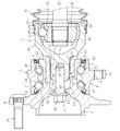
- the wheel bearing device shown in FIG. 1 includes a wheel bearing 6 including a hub wheel 1 and an inner ring 2 as inner members, double-row balls 3 and 4, and an outer ring 5 as an outer member, and a constant velocity universal joint 7.
- the main part is composed of.
- the side closer to the outer side of the vehicle body is referred to as the outboard side (left side in the drawing) and the side closer to the center is referred to as the inboard side (right side in the drawing).
- the hub wheel 1 is formed with an inner raceway surface 8 on the outboard side on the outer peripheral surface thereof and a wheel mounting flange 9 for mounting a wheel (not shown). Hub bolts 10 for fixing the wheel disc are implanted at equal intervals in the circumferential direction of the wheel mounting flange 9.
- An inner ring 2 is fitted to a small-diameter step portion 11 formed on the inboard side outer peripheral surface of the hub wheel 1, and an inner raceway surface 12 on the inboard side is formed on the outer peripheral surface of the inner ring 2.
- the inner ring 2 is press-fitted with an appropriate tightening allowance to prevent creep.
- An outboard side inner raceway surface 8 formed on the outer peripheral surface of the hub wheel 1 and an inboard side inner raceway surface 12 formed on the outer peripheral surface of the inner ring 2 constitute a double row raceway surface.
- the inner ring 2 is press-fitted into the small-diameter step portion 11 of the hub wheel 1, and the end portion of the small-diameter step portion 11 is crimped outward by swing caulking.
- the caulking portion 13 prevents the inner ring 2 from coming off and integrates it with the hub wheel 1 to apply a preload to the wheel bearing 6.
- the outer ring 5 is formed with double-row outer raceways 14 and 15 facing the inner raceways 8 and 12 of the hub wheel 1 and the inner race 2 on the inner circumference, and is attached to the vehicle body (not shown) on the outer circumference.
- a vehicle body mounting flange 16 is provided. The vehicle body mounting flange 16 is fixed to a knuckle extending from a vehicle suspension system (not shown) with a bolt or the like using the mounting hole 17.
- the wheel bearing 6 has a double-row angular contact ball bearing structure. That is, the balls 3 and 4 are interposed between the inner raceway surfaces 8 and 12 formed on the outer peripheral surfaces of the hub wheel 1 and the inner ring 2 and the outer raceway surfaces 14 and 15 formed on the inner peripheral surface of the outer ring 5. Yes.
- the balls 3 and 4 in each row are supported by the cages 18 and 19 at equal intervals in the circumferential direction. Since the wheel bearing 6 has a structure in which the inner ring 2 is prevented from coming off by the caulking portion 13 and is integrated with the hub wheel 1, it can be separated from the outer joint member 20 of the constant velocity universal joint 7. It has become.
- a pair of seals 21 and 22 for sealing the annular space between the outer ring 5, the hub wheel 1, and the inner ring 2 are provided at both ends of the wheel bearing 6.
- the seals 21 and 22 are fitted to inner diameters at both ends of the outer ring 5 to prevent leakage of a lubricant such as grease filled therein and intrusion of water and foreign matters from the outside.
- the seal 21 is composed of a cored bar and an elastic member, and the tip of the lip of the elastic member is in sliding contact with the outer peripheral surface of the hub wheel 1.
- the seal 22 is a so-called pack seal type.
- the seal 22 includes two L-shaped metal cores and an elastic member. The elastic member is attached to one metal core, and the lip of the elastic member is attached to the outer peripheral surface of the other metal core attached to the outer periphery of the inner ring. The tip is in sliding contact.
- the constant velocity universal joint 7 is a fixed constant velocity universal joint that is provided at one end of the shaft 23 constituting the drive shaft and allows only angular displacement between the two axes of the drive side and the driven side.
- the constant velocity universal joint 7 includes an outer joint member 20 in which a track groove 24 is formed on the inner peripheral surface, and an inner joint member in which a track groove 25 facing the track groove 24 of the outer joint member 20 is formed on the outer peripheral surface. 26, a ball 27 incorporated between the track groove 24 of the outer joint member 20 and the track groove 25 of the inner joint member 26, and between the inner peripheral surface of the outer joint member 20 and the outer peripheral surface of the inner joint member 26. And a cage 28 for holding the ball 27.
- the outer joint member 20 includes a cup-shaped mouth portion 29 that accommodates inner parts including the inner joint member 26, a ball 27, and a cage 28, and a stem portion 30 that extends integrally from the mouth portion 29 in the axial direction. ing.
- the inner joint member 26 is coupled to the shaft 23 so that the shaft end of the shaft 23 is press-fitted and torque can be transmitted by spline fitting.
- the boot 31 is attached and the opening of the outer joint member 20 is closed with the boot 31.
- the boot 31 includes a large-diameter end portion fastened and fixed to the outer peripheral surface of the outer joint member 20 by a boot band, a small-diameter end portion fastened and fixed to the outer peripheral surface of the shaft 23 by a boot band, a large-diameter end portion and a small-diameter portion. It is composed of a flexible bellows portion connected to the end portion and reduced in diameter from the large diameter end portion toward the small diameter end portion.
- the wheel bearing device has a base portion 32 of the stem portion 30 of the outer joint member 20 having a cylindrical shape, and a plurality of protrusions extending in the axial direction from the root portion 32 to the outer peripheral surface on the outboard side.
- a male spline composed of the portion 33 is formed.
- the tip portion 35 of the shaft hole 34 of the hub wheel 1 is formed in a cylindrical shape, and the circumferential side wall portion 71 of the convex portion 33 (see FIG. 5B) from the tip portion 35 to the inner peripheral surface on the outboard side.
- a plurality of concave portions 36 having a tightening allowance n only with respect to each other are formed.
- the concave portion 36 is set smaller than the convex portion 33 so as to have a tightening allowance n only with respect to the circumferential side wall portion 71 of the convex portion 33.
- the circumferential dimension of the concave portion 36 may be made smaller than the convex portion 33.
- tip part 72 of the convex part 33 does not have the interference with the recessed part 36, the radial direction dimension of the recessed part 36 is made into the convex part 33.
- the concave portion 36 has a gap p with respect to the radial front end portion 72 of the convex portion 33.
- the stem portion 30 of the outer joint member 20 is press-fitted into the shaft hole 34 of the hub wheel 1, and the hub wheel that is a mating recess forming surface is formed.
- the concave portion 37 is formed by transferring the shape of the circumferential side wall portion 71 of the convex portion 33 to one shaft hole 34 (see FIGS. 6A and 6B).
- the radial front end portion 72 of the convex portion 33 does not have an interference with the concave portion 36, the shape of the radial front end portion 72 of the convex portion 33 is not transferred to the concave portion 36.
- the recess forming surface is cut slightly by the circumferential side wall portion 71 of the projection 33, and the recess forming surface by the circumferential side wall portion 71 of the projection 33 is extremely small.
- the shape of the circumferential side wall portion 71 of the convex portion 33 is transferred to the concave portion forming surface while accompanying plastic deformation and elastic deformation.
- the convex portion 33 bites into the concave portion forming surface, so that the inner diameter of the hub wheel 1 is slightly increased, and the relative movement in the axial direction of the convex portion 33 is allowed.
- the inner diameter of the hub wheel 1 is reduced to return to the original diameter.
- the concave / convex fitting structure M is formed in which the convex portion 33 and the concave portion 37 are in close contact with each other over the entire fitting contact portion X.
- the outer joint member 20 and the hub wheel 1 can be firmly coupled and integrated.
- the gap between the stem portion 30 and the hub wheel 1 in the radial direction and the circumferential direction is not formed due to low-cost and highly reliable coupling, so the entire fitting contact region X contributes to torque transmission and enables stable torque transmission, which can prevent unpleasant rattling noise over a long period of time.
- the fitting contact region X is in close contact with each other, the strength of the torque transmission region is improved, so that the wheel bearing device can be reduced in weight and size.
- the surface hardness of the convex portion 33 is made larger than the surface hardness of the concave portion 36.
- the difference between the surface hardness of the convex portion 33 and the surface hardness of the concave portion 36 is set to 20 or more in HRC.
- the shape of the circumferential side wall portion 71 of the convex portion 33 can be easily transferred to the concave portion forming surface on the other side, accompanied by a slight plastic deformation or elastic deformation of the concave portion forming surface by the direction side wall portion 71. .
- a guide portion for guiding the start of press-fitting is provided on the inboard side of the recess 36 formed in advance in the shaft hole 34 of the hub wheel 1.
- the guide portion is formed with a concave portion 38 larger than the convex portion 33 of the stem portion 30 (see an enlarged portion in FIG. 2). That is, a gap m is formed between the convex portion 33 and the concave portion 38.
- the housing portion 40 is formed between the shaft end of the stem portion 30 of the outer joint member 20 and the inner peripheral surface of the shaft hole 34 of the hub wheel 1 by making the shaft end small.
- the wheel bearing device includes a screw tightening structure N as described below, and the operation of press-fitting the stem portion 30 of the outer joint member 20 into the shaft hole 34 of the hub wheel 1 is performed as follows.
- the screw tightening structure N is used.
- the screw tightening structure N includes an internal thread portion 41 formed at the shaft end of the stem portion 30 of the outer joint member 20 and a bolt 42 that is an external thread portion that is engaged with the internal thread portion 41 and is locked to the hub wheel 1. It consists of and.
- the bolt 42 is inserted into the through hole 44 of the projecting wall portion 43 formed in the shaft hole 34 of the hub wheel 1 and screwed into the female screw portion 41 of the stem portion 30.
- the recess 30 When the recess 30 is formed by transferring the shape of the circumferential side wall 71 of the convex portion 33 to the shaft hole 34 of the hub wheel 1 when the stem portion 30 is press-fitted into the hub wheel 1, the circumferential side wall of the convex portion 33 is formed. Since the concave portion 36 having the tightening allowance n only for the portion 71, that is, the concave portion 36 whose circumferential dimension is set smaller than the convex portion 33 is formed in advance (see FIG. 5B), the bolt 42 is tightened.
- the outer joint member 20 can be press-fitted into the hub wheel 1 with a generated axial force or less. That is, it becomes easy to press-fit the outer joint member 20 into the hub wheel 1 of the wheel bearing 6 with the pulling force of the bolt 42 to couple the constant velocity universal joint 7 to the wheel bearing 6. It is possible to improve the performance and prevent damage to the parts during the assembly.
- the outer joint member 20 when the outer joint member 20 is press-fitted into the hub wheel 1 of the wheel bearing 6, it is not necessary to prepare a dedicated jig separately, and the bolt 42, which is a component constituting the wheel bearing device, has a constant velocity.
- the universal joint 7 can be easily coupled to the wheel bearing 6.
- the pulling workability by the bolt 42 can be improved.
- it is not necessary to apply a large press-fitting load it is possible to prevent the unevenness in the concave-convex fitting structure M from being damaged (peeled), and to realize a high-quality, long-life concave-convex fitting structure M.
- the outer joint member 20 can be press-fitted into the hub wheel 1 below the axial force generated by tightening the bolt 42, the axial force generated by tightening the bolt 42 and the hub
- the difference from the axial force generated by the pressure input of the outer joint member 20 to the wheel 1 is set to 32 kN or less, preferably 28 kN or less.
- the concave portion 36 having a tightening margin n with respect to the circumferential side wall portion 71 of the convex portion 33 of the stem portion 30 of the outer joint member 20 is provided.
- the concave portion forming surface is slightly cut by the circumferential side wall portion 71 of the convex portion 33, and the concave portion forming surface by the circumferential side wall portion 71 of the convex portion 33 is formed.
- the stem portion 30 of the outer joint member 20 is press-fitted into the shaft hole 34 of the hub wheel 1 with accompanying slight plastic deformation and elastic deformation, and the circumferential side wall portion 71 of the convex portion 33 is formed in the concave portion forming surface.
- transferring the shape of this is employ
- the axial force generated on the contact surface between the crimped portion 13 of the hub wheel 1 and the shoulder 45 of the outer joint member 20 is equal to the axial force generated by the pressure input of the outer joint member 20 to the hub wheel 1.
- the axial force generated by tightening the bolt 42 can be made smaller. In this way, the surface pressure at the contact surface between the caulking portion 13 of the hub wheel 1 and the shoulder portion 45 of the outer joint member 20 can be reduced as compared with the conventional wheel bearing device.
- FIG. 7 shows the test results based on the axial force measurement performed by the present applicant.
- the axial force generated by tightening the bolt 42 and the axial force generated by the pressure input of the outer joint member 20 to the hub wheel 1 are measured.
- the present invention (Nos. 1 to 7) and comparative products (Nos. 8 to 13) were checked for the presence or absence of stick-slip noise.
- the axial force generated by tightening the bolt 42 is measured by forming a hole 47 in the head 46 of the bolt 42 and installing a strain gauge 48 embedded in the hole 47 with an adhesive 49. Use it.
- the strain gauge 48 is disposed in an embedded state in the shaft root portion 50 of the bolt 42.
- a tensile test of the bolt 42 in which the strain gauge 48 is embedded is performed in advance, and the relationship between the strain value and the axial force is calibrated.
- the axial force generated by the pressure input of the outer joint member 20 to the hub wheel 1 is measured when the stem portion 30 of the outer joint member 20 is press-fitted into the shaft hole 34 of the hub wheel 1 separately from the pull-in by the bolt 42. Connect to a tensile and compression tester and measure the pressure input.
- the axial force generated on the contact surface between the caulking portion 13 of the hub wheel 1 and the shoulder portion 45 of the outer joint member 20 is larger than 32 kN, stick slip
- produces in the contact surface of the crimping part 13 of the hub wheel 1 and the shoulder part 45 of the outer joint member 20 shall be 28 kN or less. This 28 kN is an average value of the axial force of the products of the present invention (Nos. 1 to 7).
- the convex portion 33 (the raised portion of the male spline) from the shoulder portion 45 of the outer joint member 20 with which the caulking portion 13 of the hub wheel 1 abuts.
- the value obtained by dividing the axial length L1 up to the maximum outer diameter D of the stem portion 30 is 0.3 or less, and the axial length L2 of the stem portion 30 (from the shoulder 45 to the convex portion 33 of the outer joint member 20).
- the value obtained by dividing the axial length to the outboard side end) by the maximum outer diameter D of the stem portion 30 is 1.3 or less.
- the maximum outer diameter D of the stem portion 30 means the tip end outer diameter at the convex portion 33 (male spline).
- the value obtained by dividing the axial length L1 from the shoulder 45 of the outer joint member 20 to the convex portion 33 by the maximum outer diameter D of the stem portion 30 is greater than 0.3, or the axis of the stem portion 30 If the value obtained by dividing the direction length L2 by the maximum outer diameter D of the stem portion 30 is larger than 1.3, it is difficult to ensure an effective fitting length in the concave-convex fitting structure M, or when torque is applied It becomes difficult to reduce the amount of twist of the outer joint member 20. As a result, sudden slip is likely to occur on the contact surface between the caulking portion 13 of the hub wheel 1 and the shoulder portion 45 of the outer joint member 20, and it is difficult to prevent the occurrence of stick-slip noise.
- the concave portion 36 is set smaller than the convex portion 33 so that the entire region of the concave portion 36 has a tightening margin n with respect to the circumferential side wall portion 71 and the radial tip portion 72 of the convex portion 33.
- the circumferential dimension and the radial dimension of the concave portion 36 may be made smaller than the convex portion 33.
- the convex portion 33 of the stem portion 30 is formed by the guide portion (concave portion 38). It guide
- the recess forming surface is slightly cut by the circumferential side wall portion 71 and the radial tip portion 72 of the convex portion 33, and the circumferential side wall portion 71 and the diameter of the convex portion 33 are cut.
- the shape of the circumferential side wall portion 71 and the radial tip portion 72 of the convex portion 33 is transferred to the concave portion forming surface while accompanying slight plastic deformation or elastic deformation of the concave portion forming surface by the direction leading end portion 72.
- the convex portion 33 bites into the concave portion forming surface, so that the inner diameter of the hub wheel 1 is slightly increased, and the relative movement in the axial direction of the convex portion 33 is allowed.
- the shaft hole 34 of the hub wheel 1 is reduced in diameter to return to the original diameter, and the hub wheel 1 A recess 37 is formed in the shaft hole 34.
- the circumferential side wall portion 71 of the convex portion 33 is set so as to have a tightening allowance n
- the circumferential side wall portion 71 and the radial tip portion 72 of the convex portion 33 are limited.
- the press-fit load can be lowered as compared with the embodiment in which the tightening allowance n is set.
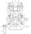
- the wheel bearing device of the embodiment shown in FIG. 12 to FIG. 27 has a seal structure for preventing muddy water or the like from entering the uneven fitting structure M for the purpose of rust prevention of the uneven fitting structure M. To do.
- the configuration other than the seal structure is the same as that of the above-described embodiment shown in FIGS. 1 to 11, the same reference numerals as those in FIGS.
- the 12 to 15 includes a structure in which a cylindrical seal 52 is interposed between the stem portion 30 of the outer joint member 20 and the protruding wall portion 43 of the hub wheel 1.
- the seal 52 is preferably an elastic member made of rubber or resin.
- the inboard side end portion 53 of the seal 52 is fitted into and fixed to the small diameter portion of the shaft end which is the accommodating portion 40 formed in the stem portion 30 (see FIGS. 14 and 15), and the outer joint member is tightened when the bolt 42 is tightened.
- the outboard side end portion 54 of the seal 52 is pressed against the projecting wall portion 43 of the hub wheel 1 and is brought into close contact with a predetermined tightening margin (see FIGS. 12 and 13).
- 16 and 17 includes a structure in which a cylindrical seal 55 is interposed between the projecting wall portion 43 of the hub wheel 1 and the bolt 42.
- the seal 55 is preferably an elastic member made of rubber or resin.
- the seal 55 fixes the outer peripheral surface to the inner diameter of the through-hole of the projecting wall portion 43 of the hub wheel 1 with an adhesive or the like, thereby bringing the inner peripheral surface into close contact with the shaft root portion 50 of the bolt 42 with a predetermined tightening margin.
- the outer peripheral surface is brought into close contact with the inner diameter of the through hole of the projecting wall portion 43 of the hub wheel 1 with a predetermined tightening margin.
- the concave-convex fitting structure M is formed from the through hole 44 of the projecting wall portion 43 of the hub wheel 1 through which the bolt 42 is inserted. Prevents muddy water from entering.
- the seal 56 having a cylindrical shape and provided with a flange portion 57 protruding radially outward at the end portion on the outboard side is connected to the protruding wall portion 43 of the hub wheel 1 and the bolt 42. And a structure interposed therebetween.
- the seal 56 is preferably an elastic member made of rubber or resin. Since the mounting structure and the sealing function of the seal 56 are the same as those of the seal 55 in the embodiment shown in FIGS. In the case of the seal 56, since the flange portion 57 is provided at the end portion on the outboard side, the axial position of the hub wheel 1 with respect to the protruding wall portion 43 can be restricted.
- the attachment becomes easy. Furthermore, when the outer joint member 20 is pulled in with the bolts 42, the flange portion 57 can prevent the seal 56 from moving (in the position) to the inboard side. Further, when the inner peripheral surface of the seal 56 is fixed to the shaft root portion 50 of the bolt 42, the creepage distance on the outer peripheral surface that is in close contact with the inner diameter of the through hole of the projecting wall portion 43 of the hub wheel 1 can be increased and the seal The property is further improved.
- a structure in which a lip seal 60 in which a lip member 59 is attached to the inner diameter of the tip of a metal seal member 58 is interposed between the outer joint member 20 and the inner ring 2 is employed. It has.
- the lip member 59 is preferably an elastic member made of rubber or resin.
- the seal 60 is fixed by fitting the base end portion of the seal member 58 to the end portion of the inner ring 2, and the lip member 59 attached to the inner diameter of the distal end portion of the seal member 58 is fixed to the outer periphery of the shoulder portion 45 of the outer joint member 20. Close contact with the surface by elastic contact.
- the seal 60 interposed between the shoulder 45 of the outer joint member 20 and the inner ring 2 is used to fit the concave and convex portions between the caulking portion 13 of the hub wheel 1 and the shoulder 45 of the outer joint member 20. Prevents muddy water from entering the structure M.
- FIG. 22 and FIG. 23 includes a structure in which a metal labyrinth seal 61 is interposed between the outer joint member 20 and the inner ring 2.
- the seal 61 has the cylindrical base end portion 62 fitted and fixed to the end portion of the inner ring 2, and the bent distal end portion 63 is brought close to the outer peripheral surface of the shoulder portion 45 of the outer joint member 20.
- the caulking portion 13 of the hub wheel 1 and the outer joint member 20 are Muddy water or the like is prevented from entering the concave-convex fitting structure M from between the shoulder 45.
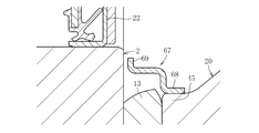
- a seal 66 with a lip in which a rubber or resin lip member 65 is attached to the tip of a metal seal member 64 is provided between the outer joint member 20 and the inner ring 2. It has an intervening structure.
- the lip member 65 is preferably an elastic member made of rubber or resin.
- the seal 66 is fixed by fitting the base end portion of the seal member 64 into the shoulder portion 45 of the outer joint member 20, and the lip member 65 attached to the distal end portion of the seal member 64 by elastic contact with the end surface of the inner ring 2. Adhere closely.
- the seal 66 interposed between the shoulder 45 of the outer joint member 20 and the inner ring 2 is used to fit the concave and convex portions between the caulking portion 13 of the hub wheel 1 and the shoulder 45 of the outer joint member 20. Prevents muddy water from entering the structure M.
- the labyrinth seal 67 made of metal is provided between the outer joint member 20 and the inner ring 2.
- the seal 67 has its cylindrical base end portion 68 fitted and fixed to the shoulder portion 45 of the outer joint member 20, and its bent distal end portion 69 is brought close to the end surface of the inner ring 2.
- the caulking portion 13 of the hub wheel 1 and the outer joint member 20 are Muddy water or the like is prevented from entering the concave-convex fitting structure M from between the shoulder 45.
- the screw tightening structure N is illustrated in which the bolt 42 is screwed to the female thread portion 41 of the stem portion 30 and the bolt 42 is fastened to the protruding wall portion 43 of the hub wheel 1.
- a male screw portion formed at the shaft end of the stem portion 30 of the outer joint member 20 and a female screw locked to the protruding wall portion 43 of the hub wheel 1 in a state of being screwed to the male screw portion. It is also possible to configure with a nut which is a part.
- the end of the small-diameter step portion 11 of the hub wheel 1 is swaged outward by swing caulking, and the inner ring 2 is prevented from coming off by the caulking portion 13 and integrated with the hub wheel 1.
- the caulking structure in which the constant velocity universal joint 7 is separable from the wheel bearing 6 is illustrated.
- the inner ring 2 is press-fitted into the small-diameter step portion 11 of the hub wheel 1, and the end of the inner ring 2 is placed outside.
- a non-caulking structure that abuts against the shoulder 45 of the joint member 20 may be used.
- one of the double-row inner raceway surfaces 8, 12 formed on the inner member composed of the hub wheel 1 and the inner ring 2, that is, the inner raceway surface 8 on the outboard side is used as the hub raceway 1.
- An example of application to a wheel bearing device of the type formed on the outer periphery (referred to as the third generation) is illustrated, but a pair of inner rings are press-fitted into the outer periphery of the hub wheel 1, and the track surface 8 on the outboard side is
- the present invention can also be applied to a type of wheel bearing device (referred to as the first and second generations) in which the inboard side raceway surface 12 is formed on the outer periphery of the other inner ring.
- the configuration in which the hub wheel and the constant velocity universal joint are fastened with bolts as in the above embodiment can be assembled and disassembled and is excellent in maintainability.
- the bolts are loosened after being assembled into the vehicle. In this case, there is a risk that a rattling occurs and abnormal noise is generated or wear is promoted.
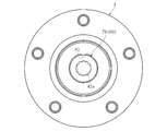
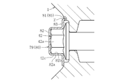
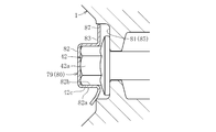
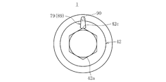
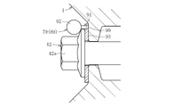
- FIG. 28 is a longitudinal sectional view of the wheel bearing device to which the first embodiment of the bolt loosening prevention structure is applied
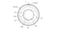
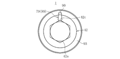
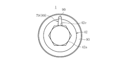
- FIG. 29 is a front view of the wheel bearing device shown in FIG. 28 as viewed from the direction of the arrow Y
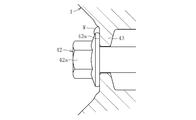
- FIG. FIG. 31 is an enlarged front view showing the main part of FIG. 29.
- the configuration of the wheel bearing device shown in FIG. 28 is basically the same as the configuration of the wheel bearing device shown in FIG.
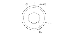
- a cap member 80 as a locking member 79 is attached to the head portion 42 a of the bolt 42 that fastens the hub wheel 1 and the constant velocity universal joint 7. . Then, the rotation of the bolt 42 in the loosening direction is restricted between the head 42 a of the bolt 42 and the hub wheel 1 via the cap member 80.
- the cap member 80 includes a bottomed cylindrical cap body 82 attached to the head portion 42 a of the bolt 42, and a flat plate circle provided at the opening edge of the cap body 82. It is comprised with the annular collar 83.
- a plurality of concave portions 82b having a shape corresponding to the corner portion 42c formed on the side surface of the head portion 42a are formed so as to be arranged at equal intervals in the circumferential direction (see FIG. 31).
- the circumferential rotation of the cap member 80 relative to the head portion 42a is restricted by fitting the cap member 80 into the head portion 42a so that the concave portion 82b is aligned with the corner portion 42c.
- the recesses 82b are provided twice (12) as many as the number of corners 42c (6 in FIG. 31) of the head 42a.
- the cap member 80 can be aligned with the head portion 42a as compared with the case where the number of concave portions 82b is the same as the number of corner portions 42c. Since the location is doubled, the fitting operation becomes easy.
- the number of recesses 82b may be three times or more than the number of corners 42c, or the number of recesses 82b may be the same as the number of corners 42c.
- the inner diameter of the side wall portion 82a of the cap body 82 is set slightly smaller than the outer diameter of the corresponding head portion 42a. That is, the cap member 80 is press-fitted into the head portion 42a and is thus fitted, and the cap member 80 is difficult to come off in the axial direction.
- the hub wheel 1 is provided with an engaging portion 81 that can be engaged with the cap member 80 on the side where the cap member 80 is disposed.
- This engaging part 81 is comprised by the protrusion part 84 protruded in a part of circumferential direction.
- FIG. 32A is a perspective view showing a state before the cap member 80 is engaged with the protrusion 84 of the hub wheel 1
- FIG. 32B is a perspective view showing a state where the cap member 80 is engaged with the protrusion 84 of the hub wheel 1. It is.
- the cap member 80 in order to engage the cap member 80 with the protrusion 84 of the hub wheel 1, the cap member 80 is disposed so as to cover the outer edge portion of the flange 83 with respect to the protrusion 84.
- the flange 83 is crimped in the vicinity of.
- the collar 83 is deformed following the shape of the projection 84, and the collar 83 is engaged with the projection 84 at the deformed portion (caulking part) Z, whereby the cap member 80 is restrained in the circumferential direction.
- the bolt 42 is restrained with respect to the hub wheel 1 via the cap member 80, thereby restricting the rotation of the bolt 42 in the loosening direction and preventing the loosening.
- protrusion 84 only one protrusion 84 is provided, but a plurality of protrusions 84 are provided in the circumferential direction, and each protrusion 84 or an arbitrarily selected protrusion among them is selected.
- the collar portion 83 may be crimped to 84.
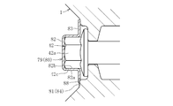
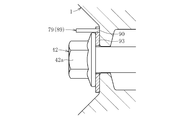
- FIG. 33 is a longitudinal sectional view of the second embodiment of the bolt locking structure, and FIG. 34 is a front view thereof.
- the shape of the engaging portion 81 provided on the hub wheel 1 is different from that in the first embodiment.
- the engaging portion 81 is a recessed portion 85 that is recessed in a part in the circumferential direction. Other than that, it is comprised similarly to 1st Embodiment.
- the cap member 80 in order to engage the cap member 80 with the recess 85, the cap member 80 is disposed so as to cover the outer edge of the flange 83 with respect to the recess 85.
- the collar portion 83 is crimped at the position of the portion 85.
- the collar portion 83 is deformed following the shape of the recess portion 85, and the cap portion 83 is engaged with the recess portion 85 by the deformed portion (caulking portion) Z, whereby the cap member 80 is restrained in the circumferential direction.
- the rotation of the bolt 42 in the loosening direction is restricted and the loosening is prevented.
- a plurality of recesses 85 are provided in the circumferential direction, and the collar portion 83 is caulked with respect to each recess 85 or an arbitrarily selected recess 85 of them. It may be processed.
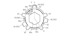
- FIG. 36 is a longitudinal sectional view of the third embodiment of the bolt locking structure, and FIG. 37 is a front view thereof.
- FIG. 36 is a sectional view taken along line GG in FIG.
- the locking member 79 is constituted by a clip member 86.
- the clip member 86 includes an opening 86c in a part in the circumferential direction and a clip main body 86a attached to the head portion 42a of the bolt 42, and a plurality of protrusions protruding in the outer diameter direction over the circumferential direction of the clip main body 86a. Part 87 (see FIG. 37).
- an insertion hole 86e for inserting the head portion 42a of the bolt 42 is formed in the same hexagonal shape as the head portion 42a of the bolt 42, and the circumferential direction of the clip member 86 with respect to the head portion 42a is set by inserting the head portion 42a into the insertion hole 86e. Rotation is regulated. Further, the inner diameter of the insertion hole 86e is set slightly smaller than the outer diameter of the corresponding head portion 42a. This makes it difficult for the clip member 86 attached to the head portion 42a to come off in the axial direction. Further, holes 86d for gripping the clip member 86 with a tool such as a plier when the clip member 86 is attached to the head portion 42a of the bolt 42 are formed at both ends forming the opening 86c of the clip body 86a.
- the hub wheel 1 is provided with a recess 85 as an engaging portion 81 that can engage with the convex portion 87 of the clip member 86 on the side where the clip member 86 is disposed.
- a plurality of recesses 85 are provided in the circumferential direction.
- the clip body 86a When the clip member 86 is attached to the head portion 42a of the bolt 42, the clip body 86a is elastically deformed so that the opening 86c is widened by grasping both ends of the clip body 86a with a pliers or the like, and the insertion hole 86e of the clip body 86a as it is. Then, the head 42a of the bolt 42 is inserted. Then, the clip main body 86 a is locked to the side surface of the head 42 a by the elastic restoring force of the clip member 86.
- one of the plurality of convex portions 87 of the clip member 86 is aligned with one arbitrarily selected concave portion 85 and inserted into the concave portion 85.
- the arrangement of the other protrusions 87 and the arrangement of the depressions 85 are arranged in a state where one protrusion 87 is aligned with the arbitrarily selected depression 85. The direction is shifted.
- one convex portion 87 and one concave portion 85 may be provided.
- FIG. 38 is a longitudinal sectional view of a fourth embodiment of the bolt loosening prevention structure, and FIG. 39 is a front view thereof.
- FIG. 38 is a sectional view taken along the line HH in FIG.
- a protrusion 87 similar to that provided on the clip member 86 is provided on the collar 83 of the cap member 80 as the locking member 79 in the circumferential direction.
- the hub wheel 1 is provided with a plurality of recesses 85 similar to the above in the circumferential direction.
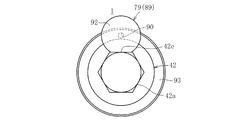
- FIG. 40 is a longitudinal sectional view of a fifth embodiment of the bolt loosening prevention structure, and FIG. 41 is a front view thereof.
- FIG. 40 is a cross-sectional view taken along the line II of FIG.
- the hub wheel 1 is provided with a projection 84 as an engagement portion 81, and the clip member 86 is provided with a recess 88 that can be engaged with the projection 84.
- the clip member 86 is provided with a recess 88 that can be engaged with the projection 84.
- FIG. only one protrusion 84 and one recess 88 are provided, but a plurality of protrusions 84 and recesses 88 may be provided side by side in the circumferential direction.
- the clip body 86a is elastically deformed and the clip member 86 is attached to the head portion 42a of the bolt 42 in the same manner as described above.
- the concave portion 88 of the clip member 86 is formed on the protrusion 84 of the hub wheel 1. Align. As a result, the recess 88 becomes engageable with the protrusion 84 in the circumferential direction, and the rotation of the bolt 42 in the loosening direction is restricted via the clip member 86.
- FIG. 42 is a longitudinal sectional view of a sixth embodiment of the bolt locking structure, and FIG. 43 is a front view thereof.
- FIG. 42 is a sectional view taken along line JJ in FIG.
- a recess 88 that can be engaged with the protrusion 84 of the hub wheel 1 is provided in the flange 83 of the cap member 80.
- a plurality of protrusions 84 and recesses 88 may be provided side by side in the circumferential direction.
- the recess 88 of the cap member 80 is aligned with the protrusion 84 of the hub wheel 1.
- the recess 88 can engage with the protrusion 84 in the circumferential direction, and the rotation of the bolt 42 in the loosening direction is restricted via the cap member 80.
- 44A and 44B are longitudinal sectional views of a seventh embodiment of the bolt loosening prevention structure.
- 44A shows a state before the cap member 80 is completely press-fitted into the head portion 42a of the bolt 42
- FIG. 44B shows a state where the cap member 80 is completely press-fitted into the head portion 42a of the bolt 42.
- the side wall 82a of the cap body 82 is formed in a tapered shape such that the inner diameter increases toward the opening side. With this configuration, the cap member 80 can be easily pressed into the head portion 42a of the bolt 42.
- the cap member 80 provided with the convex portion 87 is configured in a tapered shape, but the cap member 80 is similarly formed in a tapered shape for the cap members 80 having other configurations. May be.
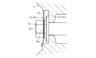
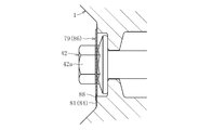
- FIG. 45 is a longitudinal sectional view of an eighth embodiment of the bolt locking structure, and FIG. 46 is a front view thereof.
- the bolt 42 is configured to be loosened by using the loosening prevention member 79 (cap member 80 or clip member 86).
- the loosening prevention member 79 is not used.
- a thin flange portion 42 d is provided on the head portion 42 a of the bolt 42, and this flange portion 42 d is directly engaged with a projection portion 84 as an engagement portion 81 provided on the hub wheel 1. .
- the bolt 42 is screwed into the female thread portion 41 (see FIG. 1) of the constant velocity universal joint 7, the constant velocity universal joint 7 is fastened to the hub wheel 1, and then the flange portion 42 d of the bolt 42 is attached in the vicinity of the protruding portion 84. Clamp.
- the flange portion 42d is deformed following the shape of the protruding portion 84, similarly to the flange portion 83 shown in FIG. 32B, and the flange portion 42d is deformed with respect to the protruding portion 84 at the deformed portion (caulking portion) Z.
- Engage the bolt 42 is restrained in the circumferential direction with respect to the hub wheel 1.
- the rotation of the bolt 42 in the loosening direction can be restricted between the head portion 42a of the bolt 42 and the hub wheel 1 by caulking the flange portion 42d of the bolt 42. Is possible.
- the flange portion 42d is not heat-cured so that it can be easily crimped. It is also possible to provide a plurality of protrusions 84 in the circumferential direction and caulk the flange portion 42d to each protrusion 84 or to an arbitrarily selected protrusion 84 of them. is there.
- FIG. 47 is a longitudinal sectional view of a ninth embodiment of the bolt locking structure, and FIG. 48 is a front view thereof.
- a thin flange portion 42d similar to the above is provided on the head portion 42a of the bolt 42, and this flange portion 42d is used as the engaging portion 81 provided on the hub wheel 1.
- the recess 85 is directly engaged.
- the bolt 42 is screwed into the female thread portion 41 (see FIG. 1) of the constant velocity universal joint 7, the constant velocity universal joint 7 is fastened to the hub wheel 1, and then the flange portion of the bolt 42 at the position of the recess 85. Clamp 42d.
- the flange portion 42d is deformed following the shape of the recessed portion 85, similarly to the flange portion 83 shown in FIG. 35B, and the flange portion 42d is deformed with respect to the recessed portion 85 at the deformed portion (caulking portion) Z.
- Engage Thereby, the bolt 42 is restrained in the circumferential direction with respect to the hub wheel 1.
- the flange portion 42d is not heat-cured so that it can be easily crimped. It is also possible to provide a plurality of recesses 85 in the circumferential direction and caulk the flange portion 42d to each recess 85 or to an arbitrarily selected recess 85 of them. is there.
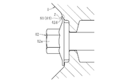
- FIG. 49 is a longitudinal sectional view of a tenth embodiment of the bolt locking structure, and FIG. 50 is a front view thereof.
- the head portion 42a of the bolt 42 and the hub wheel 1 are fixed by welding the head portion 42a of the bolt 42 to the hub wheel 1 (by the welded portion W).
- the rotation of the bolt 42 in the loosening direction is restricted.
- the head portion 42a of the bolt 42 is spot-welded at a plurality of locations in the circumferential direction with respect to the radial end surface 43a of the projecting wall portion 43 of the hub wheel 1 with which the bolt 42 abuts.
- the welding means known means such as laser welding or electron beam welding can be used.
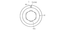
- FIGS. 51A and 51B are longitudinal sectional views of an eleventh embodiment of the bolt locking structure
- FIG. 51A is a diagram showing a state before the locking member is crimped
- FIG. 51B is after the locking process of the locking member It is a figure which shows the state of. 52A and 52B are front views of FIGS. 51A and 51B.
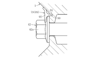
- a pin-shaped member 89 is used as the locking member 79.
- the pin-shaped member 89 has a shaft-shaped insertion portion 91 that can be inserted into an insertion hole 90 provided in the hub wheel 1, and a deformation portion 92 that is formed integrally therewith. Further, the insertion hole 90 is formed in a radial surface on which the head portion 42 a of the bolt 42 of the hub wheel 1 abuts.
- the deformed portion 92 has a spherical shape before the caulking process.
- the tip of the insertion portion 91 of the pin-shaped member 89 is inserted into the insertion hole 90 with the bolt 42 fastened to the hub wheel 1.
- the spherical deformable portion 92 exposed from the insertion hole 90 is swaged and deformed into a flat shape.
- the deformed deformed portion 92 comes into close contact with the head portion 42a of the bolt 42 and engages with each other, whereby the rotation of the bolt 42 in the loosening direction is restricted between the head portion 42a of the bolt 42 and the hub wheel 1. Is done.
- the crimped deformed portion 92 is brought into close contact with the corner portion 42c of the head portion 42a of the bolt 42. However, as shown in FIG. 53, the deformed portion 92 with respect to the flat portion 42e of the head portion 42a. May be adhered. It is preferable that the pin-shaped member 89 is not heat-cured (as it is as mild steel) so that it can be easily crimped.
- the pin-shaped member 89 is formed in a straight bar shape.
- FIGS. 54A and 55A after the tip of the pin-shaped member 89 is inserted into the insertion hole 90, it is exposed from the insertion hole 90 of the pin-shaped member 89 as shown in FIGS. 54B and 55B.
- the part to be bent is swaged and deformed.
- the end of the pin-shaped member 89 is in close contact with the head portion 42a of the bolt 42 and is engaged with each other, whereby the bolt 42 rotates in the loosening direction between the head portion 42a of the bolt 42 and the hub wheel 1. Is regulated.
- the portion where the pin-shaped member 89 is closely attached may be the corner portion 42c on the side surface of the head portion 42a as shown in FIG. 55B, or the side portion of the head portion 42a as shown in FIG.
- the plane part 42e may be sufficient.
- FIGS. 57A and 57B are longitudinal sectional views of a twelfth embodiment of the bolt locking structure
- FIG. 57A is a diagram showing a state before the locking member is crimped
- FIG. 57B is after the locking process of the locking member It is a figure which shows the state of. 58A and 58B are front views of FIGS. 57A and 57B.
- a washer 93 is interposed between the hub wheel 1 and the head 42a of the bolt 42.
- the washer 93 is provided with the insertion hole 90.
- it is basically the same as the embodiment shown in FIGS. 51A, 51B, 52A, 52B and 53.
- the tip of the insertion portion 91 of the pin-shaped member 89 is inserted into the insertion hole 90 (see FIG. 57A).
- the spherical deformable portion 92 is swaged and deformed into a flat shape (see FIG. 57B).
- the deformed deformed portion 92 comes into close contact with the head portion 42a of the bolt 42 and engages with each other, whereby the rotation of the bolt 42 in the loosening direction is restricted.
- the portion of the bolt 42 that closely contacts the pin-shaped member 89 may be the corner portion 42c on the side surface of the head portion 42a (see FIG. 58B), or the flat portion 42e on the side surface of the head portion 42a. (See FIG. 59).
- the washer 93 it is desirable to use a knurled one on both sides so that it is difficult to rotate in the circumferential direction, or a spring washer.
- a pin-like member 89 formed in a straight bar shape may be inserted into the insertion hole 90 provided in the washer 93.
- the portion exposed from the insertion hole 90 is bent with the pin-like member 89 inserted into the insertion hole 90. It is deformed by crimping. Accordingly, the end of the pin-shaped member 89 is in close contact with the head portion 42a of the bolt 42 and is engaged with each other, whereby the rotation of the bolt 42 in the loosening direction can be restricted.
- the portion of the bolt 42 that closely contacts the pin-shaped member 89 may be the corner portion 42c on the side surface of the head portion 42a (see FIG. 61B), or the flat portion 42e on the side surface of the head portion 42a. It is also possible (see FIG. 62).
- each embodiment of the bolt loosening prevention structure has been described.
- the rotation of the bolt in the loosening direction with respect to the hub wheel is performed between the head of the bolt and the hub wheel.
- the bolts are prevented from being loosened by the bolt heads exposed from the hub wheel, it is possible to easily confirm from the outside whether or not the looseness is secured after fastening the bolts.
- the bolt loosening prevention structure according to each of the above embodiments is not limited to being applied to the above-described wheel bearing device.
- the bolt loosening prevention structure can also be applied to a wheel bearing device as shown in FIG. 63, FIG. 64, or FIG.
- the wheel bearing device shown in FIG. 63 includes an inner member 200, an outer member 205, and a wheel bearing 220 including double rows of balls 203 and 204 interposed therebetween, and on the other hand, a fixed type constant velocity universal joint 206 fastened with a bolt 250 is a main component.
- the inner member 200 includes a hub wheel 201 provided with a wheel mounting flange 209 for mounting a wheel (not shown), and an inner ring 202 attached to the outer peripheral surface of the hub wheel 201.
- Inner raceway surfaces 207 and 208 are formed on the outer peripheral surfaces of the hub wheel 201 and the inner ring 202, respectively.
- the outer member 205 is formed with double-row outer raceway surfaces 213 and 214 facing the inner raceway surfaces 207 and 208 of the hub wheel 201 and the inner ring 202 on the inner circumferential surface thereof. Double-row balls 203 and 204 are interposed between the outer raceway surfaces 213 and 214 and the inner raceway surfaces 207 and 208 facing each other.
- the constant velocity universal joint 206 includes an outer joint member 224 having a track groove 223 formed on the inner peripheral surface and an inner joint member 226 having a track groove 225 facing the track groove 223 of the outer joint member 224 formed on the outer peripheral surface. And a ball 227 incorporated between these track grooves 223 and 225, a cage 228 for holding the ball 227 interposed between the inner peripheral surface of the outer joint member 224 and the outer peripheral surface of the inner joint member 226, etc. It consists of
- the outer joint member 224 includes a mouse part 229 that accommodates internal parts including the inner joint member 226, the ball 227, and the cage 228, and a stem part 230 that extends integrally from the mouse part 229 in the axial direction. Further, on the outer peripheral surface of the stem portion 230, a male spline 237 composed of a plurality of convex portions extending in the axial direction is formed.
- a female spline 239 that fits with the male spline 237 of the stem portion 230 is formed on the inner peripheral surface of the hole 238 of the hub wheel 201.
- a screw hole 240 is formed in the stem portion 230.
- the bolt 250 is inserted into the screw hole 240, and the bolt 250 is screwed into the female screw portion 241 formed in the screw hole 240, and the head 250 a of the bolt 250 is brought into contact with the end face 210 in the radial direction of the hub wheel 201.
- the constant velocity universal joint 206 is fastened to the hub wheel 201.
- the wheel bearing device shown in FIG. 64 is similar to the wheel bearing device shown in FIG. 63, and includes an inner member 200, an outer member 205, and double-row balls 203, 204 interposed therebetween.
- the main component is a wheel bearing 220 composed of the above and a fixed type constant velocity universal joint 206 fastened thereto with a bolt 250.
- a disc-shaped axial alignment protrusion 231 is integrally provided on the mouse portion 229 of the constant velocity universal joint 206.
- the hub wheel 201 and the constant velocity universal joint 206 are connected with their axes aligned.
- face splines 242 and 243 are formed on the mutually opposing surfaces of the mouth portion 229 and the hub wheel 201 of the outer joint member 224, and these are engaged.
- Each of the face splines 242, 243 is formed by alternately forming a plurality of convex portions and concave portions extending in the radial direction along the circumferential direction. The engagement between these face splines 242 and 243 eliminates the circumferential shift between the hub wheel 201 and the fixed type constant velocity universal joint 206.
- a screw hole 240 into which the bolt 250 is inserted is formed in the outer joint member 224 of the constant velocity universal joint 206.
- the bolt 250 is screwed into the female screw portion 241 formed in the screw hole 240, and the head 250a of the bolt 250 is brought into contact with the radial end surface 210 of the hub wheel 201, whereby the constant velocity universal joint 206 is connected to the hub. Fastened to the ring 201.
- the wheel bearing device shown in FIG. 65 is less than the wheel bearing device shown in FIG. 63 in suppressing circumferential play between engaging splines and improving the workability of connecting the hub wheel and the constant velocity universal joint. Is intended.
- only one of the outer peripheral surface of the stem portion 230 of the outer joint member 224 and the hole portion 238 of the hub wheel 201 has a convex portion (male spline 237 or female spline). 239) is formed, and one of the two is press-fitted in the axial direction with respect to the other, thereby forming a concave portion in close contact with the convex portion on the other side.
- the other configuration is basically the same as that of the wheel bearing device shown in FIG. 63.
- the bolt 250 is inserted into the screw hole 240 of the stem portion 230 and tightened, whereby the constant velocity universal joint 206 is connected to the hub. Fastened to the ring 201.
- the bolt loosening prevention structure according to each of the above embodiments is also applied to the wheel bearing device for fastening the hub wheel and the constant velocity universal joint with bolts as shown in FIGS. 63, 64, 65, and the like. Therefore, it is possible to maintain the fastening state between the hub wheel and the constant velocity universal joint for a long period of time, and it is possible to suppress problems such as the generation of abnormal noise and the promotion of wear caused by loosening of the bolt fastening. It is.
Landscapes
- Engineering & Computer Science (AREA)
- Mechanical Engineering (AREA)
- General Engineering & Computer Science (AREA)
- Rolling Contact Bearings (AREA)
Abstract
内周に外側軌道面14,15を有する外輪5と、外周に内側軌道面8,12を有するハブ輪1及び内輪2と、外輪5の外側軌道面14,15とハブ輪1及び内輪2の内側軌道面8,12との間に介装されたボール3,4とからなる車輪用軸受6を備え、ハブ輪1の内径にステム部30を嵌合して車輪用軸受6に等速自在継手7をねじ締め付け構造Nにより結合させ、ハブ輪1の加締め部13に外側継手部材20の肩部45を当接させた車輪用軸受装置において、ステム部30に形成された複数の凸部33を、凸部33に対して締め代を有する複数の凹部が形成されたハブ輪1に圧入し、ハブ輪1に凸部33の形状を転写することにより、凸部33と凹部37との嵌合接触部位全域Xが密着する凹凸嵌合構造Mを構成し、ボルト42の締め付けにより発生する軸力と、ハブ輪1に対するステム部30の圧入力により発生する軸力との差を32kN以下とする。
Description
本発明は、例えば自動車の懸架装置に対して駆動車輪(FF車の前輪、FR車の後輪、4WD車の全輪)を回転自在に支持する車輪用軸受装置に関する。
従来の車輪用軸受装置は、例えば、図66に示すように、ハブ輪101、内輪102、複列のボール103,104及び外輪105からなる車輪用軸受106と等速自在継手107とで主要部が構成されている。
ハブ輪101は、その外周面にアウトボード側の内側軌道面108が形成されると共に、車輪(図示せず)を取り付けるための車輪取付フランジ109を備えている。その車輪取付フランジ109の円周方向等間隔に、ホイールディスクを固定するためのハブボルト110が植設されている。ハブ輪101のインボード側外周面に形成された小径段部111に内輪102を嵌合させ、その内輪102の外周面にインボード側の内側軌道面112が形成されている。ハブ輪101の軸孔の内周面には、等速自在継手107をトルク伝達可能に連結するための雌スプライン113が形成されている。
内輪102は、クリープを防ぐために適当な締め代をもって圧入されている。ハブ輪101の外周面に形成されたアウトボード側の内側軌道面108と、内輪102の外周面に形成されたインボード側の内側軌道面112とで複列の内側軌道面を構成している。内輪102をハブ輪101の小径段部111に圧入し、その小径段部111の端部を外側に加締め、その加締め部114でもって内輪102を抜け止めしてハブ輪101と一体化し、車輪用軸受106に予圧を付与している。
外輪105は、内周面にハブ輪101及び内輪102の内側軌道面108,112と対向する複列の外側軌道面115,116が形成され、外周面に車体(図示せず)に取り付けるための車体取付フランジ117を備えている。その車体取付フランジ117は、車体の懸架装置(図示せず)から延びるナックルに取り付け孔118を利用してボルト等で固定される。
車輪用軸受106は、複列のアンギュラ玉軸受構造である。すなわち、ハブ輪101及び内輪102の外周面に形成された内側軌道面108,112と外輪105の内周面に形成された外側軌道面115,116との間にボール103,104を介在させている。そして、各列のボール103,104をケージ119,120により円周方向等間隔に支持している。
車輪用軸受106の両端開口部には、外輪105とハブ輪101及び内輪102との環状空間を密封する一対のシール121,122が外輪105の両端部内径に嵌合されている。これにより、内部に充填されたグリース等の潤滑剤の漏洩ならびに外部からの水や異物の侵入を防止するようになっている。
等速自在継手107の外側継手部材123をハブ輪101に連結することにより、車輪用軸受装置が構成される。外側継手部材123は、内側継手部材、ボール及びケージからなる内部部品(図示せず)を収容したカップ状のマウス部124と、そのマウス部124から軸方向に一体に延びるステム部125とで構成されている。ステム部125の外周面には、ハブ輪101とトルク伝達可能に連結するための雄スプライン126が形成されている。
外側継手部材123のステム部125をハブ輪101の軸孔に圧入し、そのステム部125の端部に形成された雄ねじ部129にナット127を螺合させる。そして、そのナット127をハブ輪101の端面に係止させた状態で締め付けることにより、等速自在継手107をハブ輪101に固定している。このナット127の締め付け力(軸力)でもってハブ輪101の加締め部114に外側継手部材123の肩部128を当接させている。このようにして、ステム部125の雄スプライン126とハブ輪101の雌スプライン113を嵌合させることにより、等速自在継手107から車輪用軸受106へのトルク伝達が可能となっている。
この車輪用軸受装置では、ハブ輪101の加締め部114とその加締め部114に対向する外側継手部材123の肩部128とが、ナット127の締め付け力(軸力)でもって当接した状態にある。このことから、車両発進時、静止状態にある車輪用軸受106に対して等速自在継手107から回転トルクが負荷されると、雌雄スプライン113,126を介して外側継手部材123からハブ輪101へ回転トルクを伝達しようとする。しかしながら、このとき、外側継手部材123の捩れによりハブ輪101の加締め部114と外側継手部材123の肩部128との間で急激な滑りが発生する。この急激な滑りが原因となって、カッキン音と通称されるスティックスリップ音が発生することがある。
このスティックスリップ音を未然に防止する手段として、急激な滑りが発生しないように、ハブ輪101の加締め部114と外側継手部材123の肩部128との当接面での摩擦抵抗を大きくする手段が講じられている(例えば、特許文献1参照)。この特許文献1では、摩擦抵抗を大きくする手段として、外側継手部材123の肩部128の当接面に、放射状、楕円形状あるいはクロスハッチング状の凹凸部を形成する構造や、外側継手部材123の肩部128の当接面に、ゴムや樹脂製の間座を設けた構造が開示されている。
また、スティックスリップ音を未然に防止する他の手段として、急激な滑りが発生しないように、ハブ輪101の加締め部114と外側継手部材123の肩部128との当接面での摩擦抵抗を小さくする手段が講じられている(例えば、特許文献2参照)。この特許文献2では、ハブ輪101の加締め部114の当接面に凹溝を形成し、その凹溝内にグリースを充填するようにした構造が開示されている。
ところで、特許文献1,2に開示された従来の車輪用軸受装置では、ハブ輪101の加締め部114と外側継手部材123の肩部128との当接面での摩擦抵抗を大きくしたり、逆に、ハブ輪101の加締め部114と外側継手部材123の肩部128との当接面での摩擦抵抗を小さくしたりすることにより、急激な相対滑りが発生しないようにして、スティックスリップ音を未然に防止するようにしている。
しかしながら、摩擦抵抗を大きくする手段として、外側継手部材123の肩部128の当接面に、凹凸部を形成したり、あるいは間座を設けたりしなければならない。また、摩擦抵抗を小さくする手段として、ハブ輪101の加締め部114の当接面に凹溝を形成しなければならない。このように、当接面での摩擦抵抗を変える処理として、凹凸部の形成や凹溝の形成を必要としたり、別部材としての間座を必要とすることから、車輪用軸受装置のコストアップを招くという問題があった。
そこで、本発明は前述の問題点に鑑みて提案されたもので、その目的とするところは、当接面での摩擦抵抗を変える処理が不要で、簡便な手段によりスティックスリップ音を未然に防止し得る車輪用軸受装置を提供することにある。
前述の目的を達成するための技術的手段として、本発明は、内周に複列の外側軌道面が形成された外方部材と、外周に外側軌道面と対向する複列の内側軌道面を有し、ハブ輪及び内輪からなる内方部材と、外方部材の外側軌道面と内方部材の内側軌道面との間に介装された複列のボールとからなる車輪用軸受を備え、ハブ輪の内径に等速自在継手の外側継手部材のステム部を嵌合することにより車輪用軸受に等速自在継手をねじ締め付け構造により結合させ、内方部材の端部に外側継手部材の肩部を当接させた車輪用軸受装置において、ハブ輪と外側継手部材のステム部のうちのいずれか一方に形成されて軸方向に延びる複数の凸部を、凸部に対して締め代を有する複数の凹部が形成された他方に圧入し、その他方に凸部の形状を転写することにより、凸部と凹部との嵌合接触部位全域が密着する凹凸嵌合構造を構成し、ねじ締め付けにより発生する軸力と圧入力により発生する軸力との差を32kN以下としたことを特徴とする。
本発明では、ハブ輪と外側継手部材のステム部のうちのいずれか一方に軸方向に延びる複数の凸部を形成すると共に他方に凸部に対して締め代を有する凹部を予め形成しておく。ハブ輪と外側継手部材のステム部のうちのいずれか一方を他方に圧入することにより、凸部と凹部との嵌合接触部位全域が密着する凹凸嵌合構造を構成する。
この際、凸部により凹部形成面を極僅かに切削加工し、凸部による凹部形成面の極僅かな塑性変形や弾性変形を付随的に伴いながら、相手側の凹部形成面に凸部の形状を転写する。この時、凸部が相手側の凹部形成面に食い込んでいくことによってハブ輪の内径が僅かに拡径した状態となって、凸部の軸方向の相対的移動が許容される。凸部の軸方向相対移動が停止すれば、ハブ輪の内径が元の径に戻ろうとして縮径することになる。これによって、凸部と凹部との嵌合接触部位全域で密着し、外側継手部材とハブ輪を強固に結合一体化することができる。
ここで、凸部に対して締め代を有する凹部を予め形成していることから、ねじ締め付けにより発生する軸力以下でハブ輪に対して外側継手部材を圧入することができる。その結果、ハブ輪に外側継手部材のステム部を圧入するに際して、専用の治具を別に用意する必要がなく、車輪用軸受装置を構成する部品を利用したねじ締め付けでもって等速自在継手を簡易に車輪用軸受に結合させることができる。
本発明では、ねじ締め付けにより発生する軸力と圧入力により発生する軸力との差を32kN以下とする。このように、ねじ締め付けにより発生する軸力と圧入力により発生する軸力との差を32kN以下とすることにより、ねじ締め付けにより発生する軸力と圧入力により発生する軸力との差、つまり、内方部材の端部と外側継手部材の肩部との当接面に発生する軸力を32kN以下とすることになる。その結果、内方部材の端部と外側継手部材の肩部との当接面での面圧を小さくすることができ、車両発進時に車輪用軸受に対して等速自在継手から回転トルクが負荷された場合、当接面で急激な滑りが発生することを回避でき、スティックスリップ音の発生を未然に防止することができる。
本発明におけるねじ締め付け構造は、外側継手部材のステム部の軸端に形成された雌ねじ部と、その雌ねじ部に螺合した状態でハブ輪に係止される雄ねじ部とで構成された構造が可能である。この構造では、ステム部の雌ねじ部に雄ねじ部を螺合させることによりその雄ねじ部をハブ輪に係止させた状態で締め付けることによって、等速自在継手をハブ輪に固定することになる。
本発明における凸部は外側継手部材のステム部に設けられ、凹部はハブ輪に設けられた構造が望ましい。このような構造を採用すれば、外側継手部材のステム部をハブ輪に圧入することにより、凸部と凹部との嵌合接触部位全域が密着する凹凸嵌合構造を容易に構成することができる。
本発明では、外側継手部材のステム部に凸部が設けられ、ハブ輪に凹部が設けられた構造において、内方部材の端部が当接する外側継手部材の肩部から凸部までの軸方向長さをステム部の最大外径で除算した値を0.3以下とし、ステム部の軸方向長さをステム部の最大外径で除算した値を1.3以下とすることが望ましい。このように、ステム部の最大外径に対する軸方向長さを設定すれば、車両発進時に車輪用軸受に対して等速自在継手から回転トルクが負荷された場合、凹凸嵌合構造における有効嵌合長を確保した上で外側継手部材の捩れ量を少なくすることができる。その結果、内方部材の端部と外側継手部材の肩部との当接面で急激な滑りが発生することを確実に回避でき、スティックスリップ音の発生を未然に防止することができる。
また、車輪用軸受け装置が、ハブ輪と等速自在継手の外側継手部材とをボルトを介して締結して成る構成においては、ボルトの緩み方向の回転を、ボルトの頭部とハブ輪との間で規制することが望ましい。このようにすれば、ハブ輪と等速自在継手との締結状態を長期に亘って保持することができ、ボルトの締結に緩みが生じることによる異音の発生や摩耗の促進などの不具合を抑制することができるようになる。
ボルトの緩み方向の回転を規制するために、ハブ輪に係合部を設け、係合部に係合可能な緩み止め部材を、ボルトの頭部に取り付けてもよい。
また、前記係合部を突起部又は窪部で構成し、前記緩み止め部材を、係合部の位置又はその近傍で加締めることにより、係合部に係合可能である。
あるいは、前記係合部を突起部又は窪部で構成し、前記緩み止め部材に、係合部に係合可能な凸部又は凹部を設けてもよい。
また、前記緩み止め部材は、ボルトの頭部に対して圧入により装着可能なキャップ部材であってもよい。
また、前記緩み止め部材を、周方向の一部に開口部を有し、当該開口部が広がるように弾性変形することでボルトの頭部に取付可能なクリップ部材とすることも可能である。
また、ボルトの緩み方向の回転を規制するために、ハブ輪に係合部を設け、係合部に係合可能なフランジ部を、ボルトの頭部に設けてもよい。
また、前記係合部を突起部又は窪部で構成し、前記フランジ部を、係合部の位置又はその近傍で加締めることにより、係合部に係合可能である。
また、ボルトの緩み方向の回転を規制するために、ボルトの頭部をハブ輪に溶接することにより固定してもよい。
本発明によれば、ハブ輪と外側継手部材のステム部のうちのいずれか一方に形成されて軸方向に延びる複数の凸部を、その凸部に対して締め代を有する複数の凹部が形成された他方に圧入し、その他方に凸部の形状を転写することで凸部と凹部との嵌合接触部位全域が密着する凹凸嵌合構造を構成したことにより、凸部に対して締め代を有する凹部を予め形成していることから、ねじ締め付けにより発生する軸力以下でハブ輪に対して外側継手部材を圧入することができる。その結果、ねじ締め付けにより発生する軸力と圧入力により発生する軸力との差を32kN以下とすることにより、内方部材の端部と外側継手部材の肩部との当接面での面圧を小さくすることができ、車両発進時に車輪用軸受に対して等速自在継手から回転トルクが負荷された場合、当接面で急激な滑りが発生することを回避でき、スティックスリップ音の発生を未然に防止することができる。
本発明に係る車輪用軸受装置の実施形態を以下に詳述する。図1に示す車輪用軸受装置は、内方部材であるハブ輪1及び内輪2、複列のボール3,4、外方部材である外輪5からなる車輪用軸受6と等速自在継手7とで主要部が構成されている。なお、以下の説明では、車体に組み付けた状態で、車体の外側寄りとなる側をアウトボード側(図面左側)と称し、中央寄りとなる側をインボード側(図面右側)と称す。
ハブ輪1は、その外周面にアウトボード側の内側軌道面8が形成されると共に、車輪(図示せず)を取り付けるための車輪取付フランジ9を備えている。その車輪取付フランジ9の円周方向等間隔に、ホイールディスクを固定するためのハブボルト10が植設されている。ハブ輪1のインボード側外周面に形成された小径段部11に内輪2を嵌合させ、その内輪2の外周面にインボード側の内側軌道面12が形成されている。
内輪2は、クリープを防ぐために適当な締め代をもって圧入されている。ハブ輪1の外周面に形成されたアウトボード側の内側軌道面8と、内輪2の外周面に形成されたインボード側の内側軌道面12とで複列の軌道面を構成している。内輪2をハブ輪1の小径段部11に圧入し、その小径段部11の端部を揺動加締めにより外側に加締めている。その加締め部13でもって内輪2を抜け止めしてハブ輪1と一体化し、車輪用軸受6に予圧を付与している。
外輪5は、内周面にハブ輪1及び内輪2の内側軌道面8,12と対向する複列の外側軌道面14,15が形成され、外周面に車体(図示せず)に取り付けるための車体取付フランジ16を備えている。この車体取付フランジ16は、車体の懸架装置(図示せず)から延びるナックルに取り付け孔17を利用してボルト等で固定される。
車輪用軸受6は、複列のアンギュラ玉軸受構造である。すなわち、ハブ輪1及び内輪2の外周面に形成された内側軌道面8,12と外輪5の内周面に形成された外側軌道面14,15との間にボール3,4を介在させている。そして、各列のボール3,4をケージ18,19により円周方向等間隔に支持している。なお、車輪用軸受6は、加締め部13でもって内輪2を抜け止めしてハブ輪1と一体化した構造となっていることから、等速自在継手7の外側継手部材20と分離可能になっている。
車輪用軸受6の両端開口部には、外輪5とハブ輪1及び内輪2との環状空間を密封する一対のシール21,22が設けられている。このシール21,22は外輪5の両端部内径に嵌合され、内部に充填されたグリース等の潤滑剤の漏洩ならびに外部からの水や異物の侵入を防止する。シール21は芯金と弾性部材からなり、弾性部材のリップ先端がハブ輪1の外周面に摺接するようになっている。シール22は所謂パックシールと言うタイプである。具体的に、このシール22は、2つのL字状芯金と弾性部材からなり、一方の芯金に弾性部材が取り付けられ、内輪外周に装着した他方の芯金の外周面に弾性部材のリップ先端が摺接するようになっている。
等速自在継手7は、ドライブシャフトを構成するシャフト23の一端に設けられ、駆動側と従動側の二軸間で角度変位のみを許容する固定式等速自在継手である。この等速自在継手7は、内周面にトラック溝24が形成された外側継手部材20と、その外側継手部材20のトラック溝24と対向するトラック溝25が外周面に形成された内側継手部材26と、外側継手部材20のトラック溝24と内側継手部材26のトラック溝25との間に組み込まれたボール27と、外側継手部材20の内周面と内側継手部材26の外周面との間に介在してボール27を保持するケージ28とで構成されている。
外側継手部材20は、内側継手部材26、ボール27及びケージ28からなる内部部品を収容したカップ状のマウス部29と、そのマウス部29から軸方向に一体的に延びるステム部30とで構成されている。内側継手部材26は、シャフト23の軸端が圧入されてスプライン嵌合によりトルク伝達可能にシャフト23と結合している。
等速自在継手7の外側継手部材20とシャフト23との間に、継手内部に封入されたグリース等の潤滑剤の漏洩を防ぐと共に継手外部からの異物侵入を防止するための樹脂製の蛇腹状ブーツ31を装着して、外側継手部材20の開口部をブーツ31で閉塞した構造としている。このブーツ31は、外側継手部材20の外周面にブーツバンドにより締め付け固定された大径端部と、シャフト23の外周面にブーツバンドにより締め付け固定された小径端部と、大径端部と小径端部とを繋ぎ、その大径端部から小径端部へ向けて縮径した可撓性の蛇腹部とで構成されている。
この車輪用軸受装置は、図2に示すように、外側継手部材20のステム部30の根元部位32を円柱形状とし、その根元部位32からアウトボード側の外周面に軸方向に延びる複数の凸部33からなる雄スプラインを形成する。これに対して、ハブ輪1の軸孔34の先端部位35を円筒形状とし、その先端部位35からアウトボード側の内周面に前述の凸部33の周方向側壁部71(図5B参照)のみに対して締め代nを有する複数の凹部36を形成する。凹部36は、凸部33の周方向側壁部71のみに対して締め代nを有するように凸部33よりも小さく設定されている。このように凹部36を凸部33よりも小さく設定するには、凹部36の周方向寸法を凸部33よりも小さくすればよい。また、凸部33の周方向側壁部71を除く部位、つまり、凸部33の径方向先端部72は、凹部36と締め代を有さないことから、凹部36の径方向寸法を凸部33よりも大きく設定することにより、凹部36が凸部33の径方向先端部72に対して隙間pを有する。
この車輪用軸受装置では、図3、図5A及び図5Bに示すように、外側継手部材20のステム部30をハブ輪1の軸孔34に圧入し、相手側の凹部形成面であるハブ輪1の軸孔34に凸部33の周方向側壁部71の形状を転写することにより凹部37を形成する(図6A、図6B参照)。なお、凸部33の径方向先端部72は、凹部36と締め代を有さないことから、凸部33の径方向先端部72の形状が凹部36に転写されることはない。ステム部30を軸孔34に圧入するに際して、凸部33の周方向側壁部71により凹部形成面を極僅かに切削加工し、凸部33の周方向側壁部71による凹部形成面の極僅かな塑性変形や弾性変形を付随的に伴いながら、その凹部形成面に凸部33の周方向側壁部71の形状を転写することになる。この時、凸部33が凹部形成面に食い込んでいくことによってハブ輪1の内径が僅かに拡径した状態となって、凸部33の軸方向の相対的移動が許容される。この凸部33の軸方向相対移動が停止すれば、ハブ輪1の内径が元の径に戻ろうとして縮径することになる。
このようにして、凸部33と凹部37との嵌合接触部位全域Xで密着した凹凸嵌合構造Mを構成する。これにより、外側継手部材20とハブ輪1を強固に結合一体化することができる。この凹凸嵌合構造Mでは、低コストで信頼性の高い結合により、ステム部30とハブ輪1の嵌合部分の径方向及び周方向においてガタが生じる隙間が形成されないので、嵌合接触部位全域Xがトルク伝達に寄与して安定したトルク伝達が可能となり、耳障りな歯打ち音を長期に亘り防止できる。このように、嵌合接触部位全域Xで密着していることから、トルク伝達部位の強度が向上するため、車輪用軸受装置の軽量コンパクト化が図れる。
ここで、凸部33の表面硬度を凹部36の表面硬度よりも大きくする。その場合、凸部33の表面硬度と凹部36の表面硬度との差をHRCで20以上とする。これにより、外側継手部材20のステム部30をハブ輪1の軸孔34に圧入するに際して、凸部33の周方向側壁部71により凹部形成面を極僅かに切削加工し、凸部33の周方向側壁部71による凹部形成面の極僅かな塑性変形や弾性変形を付随的に伴いながら、相手側の凹部形成面に凸部33の周方向側壁部71の形状を容易に転写することができる。
また、図4A及び図4Bに示すように、ハブ輪1の軸孔34に予め形成された凹部36のインボード側には、圧入の開始をガイドするガイド部を設けている。このガイド部はステム部30の凸部33よりも大きめの凹部38が形成されている(図2の拡大部分参照)。つまり、凸部33と凹部38との間に隙間mが形成されている。このガイド部により、外側継手部材20のステム部30をハブ輪1に圧入するに際して、ステム部30の凸部33がハブ輪1の凹部36に確実に圧入されるように誘導することができるので、安定した圧入が可能となって圧入時の芯ずれや芯傾きなどを防止することができる。
さらに、ハブ輪1の軸孔34と外側継手部材20のステム部30との間に、圧入による凸部形状の転写(切削加工及びそれに付随する塑性変形や弾性変形)によって生じる食み出し部39を収容する収容部40を設けている(図5A及び図6A参照)。この収容部40は、外側継手部材20のステム部30の軸端を小径とすることにより、ハブ輪1の軸孔34の内周面との間に形成されている。これにより、圧入による凸部形状の転写によって生じる食み出し部39を収容部40に保持することができ、その食み出し部39が装置外の車両内などへ入り込んだりすることを阻止できる。その食み出し部39を収容部40に保持することで、食み出し部39の除去処理が不要となり、作業工数の削減を図ることができ、作業性の向上及びコスト低減を図ることができる。
この車輪用軸受装置は、図1~図3に示すように、以下のようなねじ締め付け構造Nを具備し、外側継手部材20のステム部30をハブ輪1の軸孔34に圧入する作業は、このねじ締め付け構造Nを利用する。ねじ締め付け構造Nは、外側継手部材20のステム部30の軸端に形成された雌ねじ部41と、その雌ねじ部41に螺合した状態でハブ輪1に係止される雄ねじ部であるボルト42とで構成されている。この構造では、ハブ輪1の軸孔34に形成された突壁部43の貫通孔44にボルト42を挿通させてステム部30の雌ねじ部41に螺合させている。そして、そのボルト42をハブ輪1の突壁部43に係止させた状態で締め付けることにより、等速自在継手7の外側継手部材20を引き込んで外側継手部材20のステム部30をハブ輪1の軸孔34に圧入し、等速自在継手7をハブ輪1に固定する。このボルト42の締め付けでもってハブ輪1の加締め部13に外側継手部材20の肩部45を当接させている。
ステム部30のハブ輪1への圧入時、ハブ輪1の軸孔34に凸部33の周方向側壁部71の形状を転写することにより凹部37を形成するに際して、凸部33の周方向側壁部71のみに対して締め代nを有する凹部36、つまり、周方向寸法が凸部33よりも小さく設定された凹部36を予め形成していることから(図5B参照)、ボルト42の締め付けにより発生する軸力以下でハブ輪1に対して外側継手部材20を圧入可能とすることができる。つまり、ボルト42の引き込み力でもって車輪用軸受6のハブ輪1に外側継手部材20を圧入して等速自在継手7を車輪用軸受6に結合させることが容易となり、車体への組み付けにおける作業性を向上させ、その組み付け時の部品の損傷を未然に防止することができる。
このように、車輪用軸受6のハブ輪1に外側継手部材20を圧入するに際して、専用の治具を別に用意する必要がなく、車輪用軸受装置を構成する部品であるボルト42でもって等速自在継手7を簡易に車輪用軸受6に結合させることができる。また、ボルト42の締め付けにより発生する軸力以下という比較的小さな引き込み力の付与で圧入することができるので、ボルト42による引き込み作業性の向上が図れる。さらに、大きな圧入荷重を付与しないので済むことから、凹凸嵌合構造Mでの凹凸が損傷する(むしれる)ことを防止でき、高品質で長寿命の凹凸嵌合構造Mを実現できる。
以上のようなボルト42の締め付けでもってハブ輪1の加締め部13に外側継手部材20の肩部45を当接させたねじ締め付け構造Nとしている。この車輪用軸受装置では、ボルト42の締め付けにより発生する軸力以下でハブ輪1に対して外側継手部材20を圧入可能とすることができることから、ボルト42の締め付けにより発生する軸力と、ハブ輪1に対する外側継手部材20の圧入力により発生する軸力との差を32kN以下、好ましくは28kN以下とする。これは、ボルト42の締め付けにより発生する軸力と、ハブ輪1に対するステム部30の圧入力により発生する軸力との差、つまり、ハブ輪1の加締め部13と外側継手部材20の肩部45との当接面に発生する軸力を32kN以下とすることになる。
ここで、従来の車輪用軸受装置(図66参照)では、ハブ輪101の軸孔の雌スプライン113と外側継手部材123のステム部125の雄スプライン126との嵌合構造を採用している。このことから、ナット127の締め付けにより発生する軸力が、ハブ輪101の加締め部114と外側継手部材123の肩部128との当接面に発生する軸力となる。つまり、ナット127の締め付けにより発生する軸力と、ハブ輪101の加締め部114と外側継手部材123の肩部128との当接面に発生する軸力とは等しい。
これに対して、この実施形態の車輪用軸受装置では、ボルト42の締め付け時、外側継手部材20のステム部30の凸部33の周方向側壁部71に対して締め代nを有する凹部36がハブ輪1の軸孔34に予め形成された状態で、その凸部33の周方向側壁部71により凹部形成面を極僅かに切削加工し、凸部33の周方向側壁部71による凹部形成面の極僅かな塑性変形や弾性変形を付随的に伴いながら、外側継手部材20のステム部30がハブ輪1の軸孔34に圧入され、その凹部形成面に凸部33の周方向側壁部71の形状を転写することにより凹部37を形成した構造を採用している(図5A、図5B参照)。このことから、ボルト42の締め付けにより発生する軸力と、ハブ輪1に対する外側継手部材20の圧入力により発生する軸力との差が、ハブ輪1の加締め部13と外側継手部材20の肩部45との当接面に発生する軸力となる。
つまり、ハブ輪1の加締め部13と外側継手部材20の肩部45との当接面に発生する軸力を、ハブ輪1に対する外側継手部材20の圧入力により発生する軸力の分だけ、ボルト42の締め付けにより発生する軸力よりも小さくすることができる。このようにして、従来の車輪用軸受装置の場合よりも、ハブ輪1の加締め部13と外側継手部材20の肩部45との当接面での面圧を小さくすることができ、車両発進時に車輪用軸受6に対して等速自在継手7から回転トルクが負荷された場合、当接面で急激な滑りが発生することを回避でき、スティックスリップ音の発生を未然に防止することができる。
図7は、本出願人が行った軸力測定に基づく試験結果であり、ボルト42の締め付けにより発生する軸力と、ハブ輪1に対する外側継手部材20の圧入力により発生する軸力を測定し、本発明品(No.1~7)と比較品(No.8~13)について、スティックスリップ音の有無を確認したものである。
なお、ボルト42の締め付けにより発生する軸力の測定は、図8に示すように、ボルト42の頭部46に孔47を形成し、その孔47に接着剤49で埋め込まれた歪みゲージ48を利用して行う。この歪みゲージ48は、ボルト42の軸部根元部位50の内部に埋設状態で配置されている。歪みゲージ48で測定される歪み値を軸力に換算するには、歪みゲージ48を埋め込んだボルト42の引張試験を予め行っておき、歪み値と軸力との関係を較正する。また、ハブ輪1に対する外側継手部材20の圧入力により発生する軸力の測定は、ボルト42による引き込みとは別に、ハブ輪1の軸孔34に外側継手部材20のステム部30を圧入する際に、引張圧縮試験機に接続し、圧入力を測定する。
この軸力測定に基づく試験では、図7に示すように、ボルト42の締め付けにより発生する軸力と、ハブ輪1に対する外側継手部材20の圧入力により発生する軸力との差、つまり、ハブ輪1の加締め部13と外側継手部材20の肩部45との当接面に発生する軸力が32kN以下となる本発明品(No.1~7)では、スティックスリップ音が発生しなかった。これに対して、ハブ輪1の加締め部13と外側継手部材20の肩部45との当接面に発生する軸力が32kNより大きくなる比較品(No.8~13)では、スティックスリップ音が発生するという結果が得られた。なお、ハブ輪1の加締め部13と外側継手部材20の肩部45との当接面に発生する軸力は28kN以下とすることが好ましい。この28kNは、本発明品(No.1~7)の軸力の平均値である。
また、この実施形態の車輪用軸受装置では、図2に示すように、ハブ輪1の加締め部13が当接する外側継手部材20の肩部45から凸部33(雄スプラインの切り上がり部)までの軸方向長さL1をステム部30の最大外径Dで除算した値を0.3以下とし、ステム部30の軸方向長さL2(外側継手部材20の肩部45から凸部33のアウトボード側端部までの軸方向長さ)をステム部30の最大外径Dで除算した値を1.3以下としている。ここで、ステム部30の最大外径Dとは、凸部33(雄スプライン)での尖端部外径を意味する。
このように、ステム部30の最大外径Dに対する軸方向長さL1,L2を設定することにより、車両発進時に車輪用軸受6に対して等速自在継手7から回転トルクが負荷された場合、凹凸嵌合構造Mにおける有効嵌合長を確保した上で外側継手部材20の捩れ量を少なくすることができる。その結果、ハブ輪1の加締め部13と外側継手部材20の肩部45との当接面で急激な滑りが発生することを確実に回避でき、スティックスリップ音の発生をより一層確実に防止することができる。
なお、外側継手部材20の肩部45から凸部33までの軸方向長さL1をステム部30の最大外径Dで除算した値が0.3よりも大きいか、あるいは、ステム部30の軸方向長さL2をステム部30の最大外径Dで除算した値が1.3よりも大きいと、凹凸嵌合構造Mにおける有効嵌合長を確保することが困難となったり、トルク負荷時における外側継手部材20の捩れ量を少なくすることが困難となる。その結果、ハブ輪1の加締め部13と外側継手部材20の肩部45との当接面で急激な滑りが発生し易く、スティックスリップ音の発生を防止することが困難となる。
以上の実施形態では、凸部33の周方向側壁部71(図5B参照)のみに対して締め代nを有するように設定した場合について説明した。これに限らず、図9A及び図9B~図11A及び図11Bに示す実施形態のように、凸部33の周方向側壁部71のみならず、その径方向先端部72を含む部位、つまり、凸部33の山形中腹部から山形頂上部に至る領域で締め代nを設定するようにしてもよい。このように、凹部36の全領域が凸部33の周方向側壁部71及び径方向先端部72に対して締め代nを有するように、その凹部36を凸部33よりも小さく設定する。このように凹部36を凸部33よりも小さく設定するには、凹部36の周方向寸法及び径方向寸法を凸部33よりも小さくすればよい。
この実施形態の場合も、図9A及び図9Bに示すように、外側継手部材20のステム部30をハブ輪1に圧入するに際して、ガイド部(凹部38)により、ステム部30の凸部33がハブ輪1の凹部36に確実に圧入されるように誘導する。そして、図10A及び図10Bに示すように、凸部33の周方向側壁部71及び径方向先端部72により凹部形成面を極僅かに切削加工し、凸部33の周方向側壁部71及び径方向先端部72による凹部形成面の極僅かな塑性変形や弾性変形を付随的に伴いながら、その凹部形成面に凸部33の周方向側壁部71及び径方向先端部72の形状を転写する。この時、凸部33が凹部形成面に食い込んでいくことによってハブ輪1の内径が僅かに拡径した状態となって、凸部33の軸方向の相対的移動が許容される。この凸部33の軸方向相対移動が停止すれば、図11A及び図11Bに示すように、ハブ輪1の軸孔34が元の径に戻ろうとして縮径することになり、ハブ輪1の軸孔34に凹部37が形成される。
なお、前述の図4A及び図4B~図6A及び図6Bに示す実施形態では、凸部33の周方向側壁部71(図5B参照)のみに対して締め代nを有するように設定している。これに対して、図9A及び図9B~図11A及び図11Bに示す実施形態では、凸部33の周方向側壁部71及び径方向先端部72(図10B参照)に対して締め代nを有するように設定している。ここで、凸部33の周方向側壁部71のみに対して締め代nを有するように設定している実施形態の場合、凸部33の周方向側壁部71及び径方向先端部72に対して締め代nを設定している実施形態の場合よりも、圧入荷重を下げることができる。
図12~図27に示す実施形態の車輪用軸受装置は、凹凸嵌合構造Mの防錆を目的として、その凹凸嵌合構造Mに泥水などが侵入することを未然に防止するシール構造を具備する。この実施形態において、シール構造以外の他の構成は、図1~図11に示す前述の実施形態と同様であるため、図1~図11と同一参照符号を付して重複説明は省略する。
図12~図15に示す実施形態では、円筒形状を有するシール52を、外側継手部材20のステム部30とハブ輪1の突壁部43との間に介在させた構造を具備する。このシール52はゴム製あるいは樹脂製の弾性部材が好ましい。シール52のインボード側端部53を、ステム部30に形成された収容部40である軸端小径部に嵌め込んで固定し(図14及び図15参照)、ボルト42の締め付け時に外側継手部材20のステム部30を引き込むことにより、シール52のアウトボード側端部54をハブ輪1の突壁部43に押し当てて所定の締め代でもって密着させる(図12及び図13参照)。このようにして、外側継手部材20のステム部30とハブ輪1の突壁部43との間に介在するシール52により、ボルト42が挿通されたハブ輪1の突壁部43の貫通孔44から泥水などが侵入しても、その泥水などが凹凸嵌合構造Mまで達することを阻止する。
図16及び図17に示す実施形態では、円筒形状を有するシール55を、ハブ輪1の突壁部43とボルト42との間に介在させた構造を具備する。このシール55はゴム製あるいは樹脂製の弾性部材が好ましい。シール55は、外周面をハブ輪1の突壁部43の貫通孔内径に接着剤などで固定することにより、内周面をボルト42の軸部根元部位50に所定の締め代でもって密着させるか、あるいは、内周面をボルト42の軸部根元部位50に接着剤などで固定することにより、外周面をハブ輪1の突壁部43の貫通孔内径に所定の締め代でもって密着させる。このようにして、ハブ輪1の突壁部43とボルト42との間に介在するシール55により、ボルト42が挿通されたハブ輪1の突壁部43の貫通孔44から凹凸嵌合構造Mへ泥水などが侵入することを阻止する。
図18及び図19に示す実施形態では、円筒形状を有し、アウトボード側端部に径方向外側に突出するフランジ部57を設けたシール56を、ハブ輪1の突壁部43とボルト42との間に介在させた構造を具備する。このシール56はゴム製あるいは樹脂製の弾性部材が好ましい。シール56の取り付け構造及びシール機能は、前述した図16及び図17の実施形態におけるシール55と同様であるため、重複説明は省略する。このシール56の場合、アウトボード側端部にフランジ部57を有することから、ハブ輪1の突壁部43に対する軸方向の位置規制が可能となる。その結果、シール56の外周面をハブ輪1の突壁部43に固定する場合、その取り付けが容易となる。さらに、ボルト42で外側継手部材20を引き込む際、フランジ部57により、シール56のインボード側への移動(位置ずれ)を防止できる。また、シール56の内周面をボルト42の軸部根元部位50に固定する場合、ハブ輪1の突壁部43の貫通孔内径に密着する外周面での沿面距離をかせぐことができてシール性がより一層向上する。
図20及び図21に示す実施形態では、金属製のシール部材58の先端部内径にリップ部材59を装着したリップ付きシール60を、外側継手部材20と内輪2との間に介在させた構造を具備する。リップ部材59はゴム製あるいは樹脂製の弾性部材が好ましい。シール60は、シール部材58の基端部を内輪2の端部に嵌め込んで固定し、そのシール部材58の先端部内径に取り付けられたリップ部材59を外側継手部材20の肩部45の外周面に弾圧接触で密着させる。このようにして、外側継手部材20の肩部45と内輪2との間に介在するシール60により、ハブ輪1の加締め部13と外側継手部材20の肩部45との間から凹凸嵌合構造Mへ泥水などが侵入することを阻止する。
図22及び図23に示す実施形態では、金属製のラビリンスシール61を、外側継手部材20と内輪2との間に介在させた構造を具備する。このシール61は、その円筒状基端部62を内輪2の端部に嵌め込んで固定し、その彎曲状先端部63を外側継手部材20の肩部45の外周面に近接させる。このようにして、外側継手部材20の肩部45と内輪2との間に介在するシール61の彎曲状先端部63でのラビリンス構造により、ハブ輪1の加締め部13と外側継手部材20の肩部45との間から凹凸嵌合構造Mへ泥水などが侵入することを阻止する。
図24及び図25に示す実施形態では、金属製のシール部材64の先端部にゴム製あるいは樹脂製のリップ部材65を装着したリップ付きシール66を、外側継手部材20と内輪2との間に介在させた構造を具備する。リップ部材65はゴム製あるいは樹脂製の弾性部材が好ましい。シール66は、シール部材64の基端部を外側継手部材20の肩部45に嵌め込んで固定し、そのシール部材64の先端部に取り付けられたリップ部材65を内輪2の端面に弾圧接触で密着させる。このようにして、外側継手部材20の肩部45と内輪2との間に介在するシール66により、ハブ輪1の加締め部13と外側継手部材20の肩部45との間から凹凸嵌合構造Mへ泥水などが侵入することを阻止する。
図26及び図27に示す実施形態では、金属製のラビリンスシール67を、外側継手部材20と内輪2との間に介在させた構造を具備する。このシール67は、その円筒状基端部68を外側継手部材20の肩部45に嵌め込んで固定し、その屈曲状先端部69を内輪2の端面に近接させる。このようにして、外側継手部材20の肩部45と内輪2との間に介在するシール67の屈曲状先端部69でのラビリンス構造により、ハブ輪1の加締め部13と外側継手部材20の肩部45との間から凹凸嵌合構造Mへ泥水などが侵入することを阻止する。
以上の実施形態では、ステム部30の雌ねじ部41にボルト42を螺合させることによりそのボルト42をハブ輪1の突壁部43に係止させた状態で締め付けるねじ締め付け構造Nを例示したが、他のねじ締め付け構造として、外側継手部材20のステム部30の軸端に形成された雄ねじ部と、その雄ねじ部に螺合した状態でハブ輪1の突壁部43に係止される雌ねじ部であるナットとで構成することも可能である。
また、以上の実施形態では、ハブ輪1の小径段部11の端部を揺動加締めにより外側に加締め、その加締め部13でもって内輪2を抜け止めしてハブ輪1と一体化することにより、等速自在継手7を車輪用軸受6から分離可能とした加締め構造を例示したが、内輪2をハブ輪1の小径段部11に圧入し、その内輪2の端部を外側継手部材20の肩部45に当接させる非加締め構造であってもよい。
さらに、以上の実施形態では、ハブ輪1及び内輪2からなる内方部材に形成された複列の内側軌道面8,12の一方、つまり、アウトボード側の内側軌道面8をハブ輪1の外周に形成した(第三世代と称される)タイプの車輪用軸受装置に適用した場合を例示したが、ハブ輪1の外周に一対の内輪を圧入し、アウトボード側の軌道面8を一方の内輪の外周に形成すると共にインボード側の軌道面12を他方の内輪の外周に形成した(第一、第二世代と称される)タイプの車輪用軸受装置にも適用可能である。
ところで、上記実施形態のような、ハブ輪と等速自在継手とをボルトで締結する構成は、組立・分解が可能でメンテナンス性に優れるが、車両組み込み後、万が一、ボルトの締結に緩みが生じると、ガタが生じて異音が発生したり、摩耗が促進されたりするなどの不具合が生じる虞がある。
そこで、以下に、長期に亘ってボルトの緩みを防止することが可能な車輪用軸受装置の構成を提案する。なお、以下の各実施形態を示す図において、同一の機能もしくは形状を有する部材や構成部品等の構成要素については、判別が可能な限り同一符号を付すことにより一度説明した後ではその説明を省略する。
図28はボルト緩み止め構造の第1実施形態を適用した車輪用軸受装置の縦断面図、図29は図28に示す車輪用軸受装置を矢印Y方向から見た正面図、図30は図28の要部を拡大して示す縦断面図、図31は図29の要部を拡大して示す正面図である。図28に示す車輪用軸受装置の構成は、図3に示す車輪用軸受け装置の構成と基本的に同様であるので、重複説明は省略する。
図28及び図29に示すように、第1実施形態では、ハブ輪1と等速自在継手7とを締結するボルト42の頭部42aに、緩み止め部材79としてのキャップ部材80を取り付けている。そして、このキャップ部材80を介して、ボルト42の頭部42aとハブ輪1との間で、ボルト42の緩み方向の回転を規制している。
詳しくは、図30及び図31に示すように、キャップ部材80は、ボルト42の頭部42aに取り付けられる有底筒状のキャップ本体82と、キャップ本体82の開口縁部に設けられた平板円環状の鍔部83とで構成されている。キャップ本体82の側壁部82aの内周面には、頭部42a側面に形成された角部42cに対応した形状の複数の凹部82bが周方向に等間隔に並ぶように形成されている(図31参照)。この凹部82bを角部42cに合わせるようにして、キャップ部材80を頭部42aに嵌め込むことで、頭部42aに対するキャップ部材80の周方向の回転が規制される。
ここでは、凹部82bを、頭部42aが有する角部42cの個数(図31では6個)の2倍(12個)設けている。このように、凹部82bを、角部42cの2倍の個数設けることで、凹部82bの個数が角部42cの個数と同じ場合に比べて、キャップ部材80を頭部42aに対して位置合わせできる箇所が2倍となるため、嵌め込み作業が容易となる。なお、凹部82bの個数を、角部42cの個数の3倍、あるいはそれ以上としてもよいし、凹部82bの個数を角部42cの個数と同数としても構わない。
また、キャップ本体82の側壁部82aの内径は、対応する頭部42aの箇所の外径よりも若干小さく設定されている。すなわち、キャップ部材80は、頭部42aに圧入して嵌め込むようになっており、キャップ部材80が軸方向に外れにくくなっている。
ハブ輪1には、キャップ部材80が配設される側に、キャップ部材80と係合可能な係合部81が設けられている。この係合部81は、周方向の一部において突出した突起部84で構成されている。
図32Aはキャップ部材80をハブ輪1の突起部84に係合させる前の状態を示す斜視図、図32Bはキャップ部材80をハブ輪1の突起部84に係合させた状態を示す斜視図である。
図32A及び図32Bに示すように、キャップ部材80をハブ輪1の突起部84に係合させるには、突起部84に対して鍔部83の外縁部を被さるように配置し、突起部84の近傍で鍔部83を加締める。この加締め加工により、鍔部83が突起部84の形状に倣って変形し、その変形した部分(加締め部)Zで鍔部83が突起部84に対して係合することにより、キャップ部材80が周方向に拘束される。このように、本実施形態では、キャップ部材80を介して、ボルト42をハブ輪1に対して拘束することにより、ボルト42の緩み方向の回転を規制し、緩み止めを行っている。
図32A及び図32Bに示すように、キャップ部材80をハブ輪1の突起部84に係合させるには、突起部84に対して鍔部83の外縁部を被さるように配置し、突起部84の近傍で鍔部83を加締める。この加締め加工により、鍔部83が突起部84の形状に倣って変形し、その変形した部分(加締め部)Zで鍔部83が突起部84に対して係合することにより、キャップ部材80が周方向に拘束される。このように、本実施形態では、キャップ部材80を介して、ボルト42をハブ輪1に対して拘束することにより、ボルト42の緩み方向の回転を規制し、緩み止めを行っている。
なお、本実施形態では、突起部84を1つだけ設けているが、突起部84を周方向に渡って複数設け、各突起部84に対して、あるいはそれらのうちの任意に選択した突起部84に対して、鍔部83を加締め加工してもよい。
図33はボルト緩み止め構造の第2実施形態の縦断面図、図34はその正面図である。
図33及び図34に示すように、第2実施形態では、ハブ輪1に設けられた係合部81の形状が、上記第1実施形態とは異なる。第2実施形態では、係合部81を、周方向の一部において窪んだ窪部85としている。それ以外は、第1実施形態と同様に構成されている。
図35A及び図35Bに示すように、第2実施形態において、キャップ部材80を窪部85に係合させるには、窪部85に対して鍔部83の外縁部を被さるように配置し、窪部85の位置で鍔部83を加締める。この加締め加工により、鍔部83が窪部85の形状に倣って変形し、その変形した部分(加締め部)Zで鍔部83が窪部85に対して係合することにより、キャップ部材80が周方向に拘束される。その結果、ボルト42の緩み方向の回転が規制され、緩み止めがなされる。
なお、本実施形態においても、窪部85を周方向に渡って複数設け、各窪部85に対して、あるいはそれらのうちの任意に選択した窪部85に対して、鍔部83を加締め加工してもよい。
図36はボルト緩み止め構造の第3実施形態の縦断面図、図37はその正面図である。また、図36は、図37のG-G線に沿う断面図である。
図36及び図37に示すように、第3実施形態では、上記各実施形態とは異なり、緩み止め部材79をクリップ部材86で構成している。このクリップ部材86は、周方向の一部に開口部86cを有すると共にボルト42の頭部42aに取り付けられるクリップ本体86aと、クリップ本体86aの周方向に渡って外径方向に突出する複数の凸部87とで構成されている(図37参照)。
クリップ本体86aの中央には、ボルト42の頭部42aを挿通するための挿通孔86eが形成されている。この場合、挿通孔86eは、ボルト42の頭部42aと同じ六角形に形成されており、頭部42aを挿通孔86eに挿通した状態にすることで、頭部42aに対するクリップ部材86の周方向の回転が規制される。また、挿通孔86eの内径は、対応する頭部42aの箇所の外径よりも若干小さく設定されている。これにより、頭部42aに取り付けられたクリップ部材86を軸方向に外れにくくしている。また、クリップ本体86aの開口部86cを形成する両端部には、クリップ部材86をボルト42の頭部42aに取り付ける際にプライヤ等の工具で掴むための孔部86dが形成されている。
一方、ハブ輪1には、クリップ部材86が配設される側に、クリップ部材86の凸部87が係合可能な係合部81としての窪部85が設けられている。窪部85は、周方向に渡って複数設けられている。
クリップ部材86をボルト42の頭部42aに取り付ける際は、プライヤ等によってクリップ本体86aの両端部を掴み、開口部86cが広がるようにクリップ本体86aを弾性変形させ、そのままクリップ本体86aの挿通孔86eにボルト42の頭部42aを挿通させる。そして、クリップ部材86の弾性復元力によって、クリップ本体86aを頭部42aの側面に係止させる。
また、このとき、クリップ部材86の複数の凸部87のうちの1つを、任意に選択した1つの窪部85に位置合わせして当該窪部85に挿入する。これにより、凸部87が窪部85に対して周方向に係合可能な状態となるため、クリップ部材86を介して、ボルト42をハブ輪1に対して周方向に拘束することができるようになる。このようにして、本実施形態では、ボルト42の緩み方向の回転を規制している。
また、図37に示すように、本実施形態では、1つの凸部87を任意に選択した窪部85に位置合わせした状態で、他の凸部87の配置と窪部85の配置とが周方向にずれるようにしている。このように構成することで、凸部87を窪部85に対して位置合わせできる箇所が増えるため、嵌め込み作業が容易になる。なお、凸部87と窪部85を、それぞれ1つずつ設ける構成としても構わない。
図38はボルト緩み止め構造の第4実施形態の縦断面図、図39はその正面図である。また、図38は、図39のH-H線に沿う断面図である。
図38及び図39に示すように、第4実施形態では、緩み止め部材79としてのキャップ部材80の鍔部83に、上記クリップ部材86に設けているのと同様の凸部87を、周方向に渡って複数設けている。一方、ハブ輪1には、上記と同様の窪部85が周方向に渡って複数設けられている。
この場合、キャップ部材80をボルト42の頭部42aに圧入する際に、上記と同様に、複数の凸部87のうちの1つを、任意に選択した1つの窪部85に位置合わせして当該窪部85に挿入する。これにより、凸部87が窪部85に対して周方向に係合可能な状態となり、キャップ部材80を介して、ボルト42がハブ輪1に対して周方向に拘束される。このようにして、本実施形態では、ボルト42の緩み方向の回転が規制される。
図40はボルト緩み止め構造の第5実施形態の縦断面図、図41はその正面図である。また、図40は、図41のI-I線に沿う断面図である。
図40及び図41に示す第5実施形態では、ハブ輪1に係合部81としての突起部84を設け、クリップ部材86に前記突起部84と係合可能な凹部88を設けている。ここでは、突起部84と凹部88とをそれぞれ1つずつしか設けていないが、それぞれ周方向に渡って複数並べて設けてもよい。
この場合、上記と同様に、クリップ本体86aを弾性変形させて、クリップ部材86をボルト42の頭部42aに取り付けるが、このとき、クリップ部材86の凹部88を、ハブ輪1の突起部84に位置合わせする。これにより、凹部88が突起部84に対して周方向に係合可能な状態となり、クリップ部材86を介して、ボルト42の緩み方向の回転が規制されるようになる。
図42はボルト緩み止め構造の第6実施形態の縦断面図、図43はその正面図である。また、図42は、図43のJ-J線に沿う断面図である。
図42及び図43に示す第6実施形態では、ハブ輪1の突起部84に対して係合可能な凹部88を、キャップ部材80の鍔部83に設けている。なお、突起部84と凹部88とをそれぞれ周方向に渡って複数並べて設けてもよい。
この場合、キャップ部材80をボルト42の頭部42aに圧入して嵌め込む際に、キャップ部材80の凹部88を、ハブ輪1の突起部84に対して位置合わせする。これにより、凹部88が突起部84に対して周方向に係合可能な状態となり、キャップ部材80を介して、ボルト42の緩み方向の回転が規制されるようになる。
図44A及び図44Bはボルト緩み止め構造の第7実施形態の縦断面図である。また、図44Aはキャップ部材80をボルト42の頭部42aに完全に圧入する前の状態を示し、図44Bはキャップ部材80をボルト42の頭部42aに完全に圧入した状態を示す。
図44A及び図44Bに示す第7実施形態では、キャップ本体82の側壁部82aを、その開口側に向かって内径が大きくなるようなテーパ形状に形成している。このように構成することで、キャップ部材80をボルト42の頭部42aに圧入しやすくなる。なお、本実施形態では、凸部87を設けたキャップ部材80をテーパ形状に構成しているが、その他の構成のキャップ部材80に対しても、同様に、キャップ部材80をテーパ形状に形成してもよい。
図45はボルト緩み止め構造の第8実施形態の縦断面図、図46はその正面図である。
上記各実施形態では、緩み止め部材79(キャップ部材80又はクリップ部材86)を用いてボルト42の緩み止めを行うように構成しているが、図45に示す第8実施形態では、上記のような緩み止め部材79を用いていない。本実施形態では、ボルト42の頭部42aに薄肉のフランジ部42dを設け、このフランジ部42dをハブ輪1に設けられた係合部81としての突起部84に対して直接係合させている。
まず、ボルト42を等速自在継手7の雌ねじ部41(図1参照)にねじ込み、等速自在継手7をハブ輪1に締結してから、突起部84の近傍でボルト42のフランジ部42dを加締める。その結果、フランジ部42dが、図32Bに示す鍔部83と同様に、突起部84の形状に倣って変形し、その変形した部分(加締め部)Zでフランジ部42dが突起部84に対して係合する。これにより、ボルト42がハブ輪1に対して周方向に拘束される。このように、本実施形態では、ボルト42のフランジ部42dを加締め加工することにより、ボルト42の頭部42aとハブ輪1との間で、ボルト42の緩み方向の回転を規制することが可能である。
なお、フランジ部42dは、加締め加工しやすいように、熱硬化処理しない方が好ましい。また、突起部84を周方向に渡って複数設け、各突起部84に対して、あるいはそれらのうちの任意に選択した突起部84に対して、フランジ部42dを加締め加工することも可能である。
図47はボルト緩み止め構造の第9実施形態の縦断面図、図48はその正面図である。
図47及び図48に示す第9実施形態では、ボルト42の頭部42aに上記と同様の薄肉のフランジ部42dを設け、このフランジ部42dをハブ輪1に設けられた係合部81としての窪部85に対して直接係合させている。
この場合も、ボルト42を等速自在継手7の雌ねじ部41(図1参照)にねじ込み、等速自在継手7をハブ輪1に締結してから、窪部85の位置でボルト42のフランジ部42dを加締める。その結果、フランジ部42dが、図35Bに示す鍔部83と同様に、窪部85の形状に倣って変形し、その変形した部分(加締め部)Zでフランジ部42dが窪部85に対して係合する。これにより、ボルト42がハブ輪1に対して周方向に拘束される。
なお、上記と同様に、加締め加工しやすいように、フランジ部42dは熱硬化処理されない方が好ましい。また、窪部85を周方向に渡って複数設け、各窪部85に対して、あるいはそれらのうちの任意に選択した窪部85に対して、フランジ部42dを加締め加工することも可能である。
図49はボルト緩み止め構造の第10実施形態の縦断面図、図50はその正面図である。
図49及び図50に示す第10実施形態では、ボルト42の頭部42aをハブ輪1に溶接して(溶接部Wによって)固定することにより、ボルト42の頭部42aとハブ輪1との間で、ボルト42の緩み方向の回転を規制している。本実施形態では、ボルト42の頭部42aを、それが当接するハブ輪1の突壁部43の径方向端面43aに対して、周方向に渡って複数箇所でスポット溶接している。溶接手段としては、レーザ溶接あるいは電子ビーム溶接などの公知の手段を用いることができる。
図51A及び図51Bはボルト緩み止め構造の第11実施形態の縦断面図であり、図51Aは緩み止め部材の加締め加工前の状態を示す図、図51Bは緩み止め部材の加締め加工後の状態を示す図である。また、図52A及び図52Bは図51A及び図51Bの正面図である。
第11実施形態では、緩み止め部材79としてピン状部材89を用いている。ピン状部材89は、ハブ輪1に設けられた挿入孔90に挿入可能な軸状の挿入部91と、これと一体的に形成された変形部92とを有する。また、挿入孔90は、ハブ輪1のボルト42の頭部42aが当接する径方向面に形成されている。
図51A及び図52Aに示すように、加締め加工前の状態では、変形部92は球形状となっている。ボルト42の緩み止め加工をするには、まず、ボルト42をハブ輪1に締結した状態で、ピン状部材89の挿入部91の先端を挿入孔90内に挿入する。そして、図51B及び図52Bに示すように、挿入孔90から露出する球形状の変形部92を叩くなどして加締めて、扁平状に変形させる。これにより、変形した変形部92がボルト42の頭部42aと密着し、互いに係合することで、ボルト42の頭部42aとハブ輪1との間で、ボルト42の緩み方向の回転が規制される。
図52Bでは、加締め加工した変形部92を、ボルト42の頭部42aの角部42cに密着させているが、図53に示すように、頭部42aの平面部42eに対して変形部92を密着させてもよい。なお、ピン状部材89は、加締め加工しやすいように、熱硬化処理しない(軟鋼のままの)方が好ましい。
図54A、図54B、図55A、図55B及び図56に示す例では、上記ピン状部材89をストレート棒状に形成している。
この場合、図54A及び図55Aに示すように、ピン状部材89の先端を挿入孔90内に挿入した後、図54B及び図55Bに示すように、当該ピン状部材89の挿入孔90から露出する部分を曲げるように加締めて変形させる。これにより、ピン状部材89の端部がボルト42の頭部42aと密着し、互いに係合することで、ボルト42の頭部42aとハブ輪1との間で、ボルト42の緩み方向の回転が規制される。
この場合、図54A及び図55Aに示すように、ピン状部材89の先端を挿入孔90内に挿入した後、図54B及び図55Bに示すように、当該ピン状部材89の挿入孔90から露出する部分を曲げるように加締めて変形させる。これにより、ピン状部材89の端部がボルト42の頭部42aと密着し、互いに係合することで、ボルト42の頭部42aとハブ輪1との間で、ボルト42の緩み方向の回転が規制される。
また、この場合も、ピン状部材89を密着させる部分は、図55Bに示すように、頭部42a側面の角部42cであってもよいし、図56に示すように、頭部42a側面の平面部42eであってもよい。
図57A及び図57Bはボルト緩み止め構造の第12実施形態の縦断面図であり、図57Aは緩み止め部材の加締め加工前の状態を示す図、図57Bは緩み止め部材の加締め加工後の状態を示す図である。図58A及び図58Bは図57A及び図57Bの正面図である。
第12実施形態では、ハブ輪1とボルト42の頭部42aとの間にワッシャ93を介装している。そして、このワッシャ93に上記挿入孔90を設けている。それ以外は、基本的に、図51A、図51B、図52A、図52B及び図53に示す実施形態と同様である。
この場合、ワッシャ93を介装してボルト42とハブ輪1とを締結した後、ピン状部材89の挿入部91の先端を挿入孔90内に挿入する(図57A参照)。そして、上記と同様に、球形状の変形部92を叩くなどして加締めて、扁平状に変形させる(図57B参照)。これにより、変形した変形部92がボルト42の頭部42aと密着し、互いに係合することで、ボルト42の緩み方向の回転が規制される。
また、この場合も、ピン状部材89を密着させるボルト42の部分は、頭部42a側面の角部42cであってもよいし(図58B参照)、頭部42a側面の平面部42eであってもよい(図59参照)。また、ワッシャ93としては、周方向へ回転しにくいように、両面にローレット加工を施したものや、スプリングワッシャを用いることが望ましい。
また、図60A、図60B、図61A、図61B及び図62に示す例のように、ワッシャ93に設けた挿入孔90に、ストレート棒状に形成されたピン状部材89を挿入してもよい。この場合、図54A、図54B、図55A、図55B及び図56に示す実施形態と同様に、ピン状部材89を挿入孔90に挿入した状態で、挿入孔90から露出する部分を曲げるように加締めて変形させる。これにより、ピン状部材89の端部がボルト42の頭部42aと密着し、互いに係合することで、ボルト42の緩み方向の回転を規制することができる。
また、この場合も、ピン状部材89を密着させるボルト42の部分は、頭部42a側面の角部42cであってもよいし(図61B参照)、頭部42a側面の平面部42eであってもよい(図62参照)。
以上、ボルト緩み止め構造の各実施形態について説明したが、各実施形態に係るボルト緩み止め構造によれば、ハブ輪に対するボルトの緩み方向の回転を、ボルトの頭部とハブ輪との間で規制することができる。これにより、ハブ輪と等速自在継手との締結状態を長期に亘って保持することが可能となる。その結果、ボルトの締結に緩みが生じることによる異音の発生や摩耗の促進などの不具合を抑制することができるようになる。
また、ボルトの緩み止めを、ハブ輪から露出したボルトの頭部でもって行うので、ボルトの締結後に緩み止めが行われているか否かについて外部から目視などで容易に確認することもできる。
また、上記各実施形態に係るボルト緩み止め構造は、上述の車輪用軸受け装置に適用する場合に限らない。例えば、図63、図64あるいは図65などに示すような車輪用軸受装置においても、上記ボルト緩み止め構造を適用可能である。
具体的に、図63に示す車輪用軸受装置は、内方部材200、外方部材205、及びこれらの間に介装された複列のボール203,204から成る車輪用軸受220と、これに対してボルト250で締結された固定式等速自在継手206とを、主要な構成要素としている。
内方部材200は、車輪(図示せず)を取り付けるための車輪取付フランジ209が設けられたハブ輪201と、ハブ輪201の外周面に装着された内輪202とで構成されている。ハブ輪201と内輪202の各外周面には、それぞれ、内側軌道面207,208が形成されている。一方、外方部材205は、その内周面に、ハブ輪201及び内輪202の各内側軌道面207,208と対向する複列の外側軌道面213,214が形成されている。これらの互いに対向する外側軌道面213,214と内側軌道面207,208との間に複列のボール203,204が介装されている。
等速自在継手206は、内周面にトラック溝223が形成された外側継手部材224と、その外側継手部材224のトラック溝223と対向するトラック溝225が外周面に形成された内側継手部材226と、これらのトラック溝223,225の間に組み込まれたボール227と、外側継手部材224の内周面と内側継手部材226の外周面との間に介在してボール227を保持するケージ228等で構成されている。
外側継手部材224は、内側継手部材226、ボール227及びケージ228から成る内部部品を収容するマウス部229と、マウス部229から軸方向に一体的に延びたステム部230とを有する。また、ステム部230の外周面には、軸方向に延びる複数の凸部から成る雄スプライン237が形成されている。
これに対し、ハブ輪201の孔部238の内周面には、ステム部230の雄スプライン237と嵌合する雌スプライン239が形成されている。孔部238にステム部230を挿入した状態で、両スプラインの係合によって、ハブ輪201と外側継手部材224はトルク伝達可能に結合される。
さらに、ステム部230には、ねじ孔240が形成されている。このねじ孔240にボルト250を挿入し、ねじ孔240に形成された雌ねじ部241にボルト250を螺合させると共に、そのボルト250の頭部250aをハブ輪201の径方向の端面210に当接させることで、等速自在継手206をハブ輪201に締結している。
また、図64に示す車輪用軸受装置は、図63に示す車輪用軸受装置と同様に、内方部材200、外方部材205、及びこれらの間に介装された複列のボール203,204から成る車輪用軸受220と、これに対してボルト250で締結された固定式等速自在継手206とを、主要な構成要素としている。
ここでは、等速自在継手206のマウス部229に、円盤状の軸合わせ用突起部231が一体的に設けられている。この軸合わせ用突起部231がハブ輪201の孔部238に嵌入されることで、ハブ輪201と等速自在継手206とが軸心を合わせて連結されている。また、この車輪用軸受装置では、外側継手部材224のマウス部229とハブ輪201との互いに対向する面に、それぞれフェーススプライン242,243を形成し、これらを係合させている。各フェーススプライン242,243は、径方向に延びる複数の凸部と凹部とが周方向に沿って交互に形成されたものである。これらのフェーススプライン242,243同士の係合によって、ハブ輪201と固定式等速自在継手206との周方向のずれを無くすようにしている。
また、この車輪用軸受装置においても、図63に示す車輪用軸受装置と同様に、等速自在継手206の外側継手部材224に、ボルト250が挿入されるねじ孔240が形成されており、このねじ孔240に形成された雌ねじ部241にボルト250を螺合させると共に、そのボルト250の頭部250aをハブ輪201の径方向の端面210に当接させることで、等速自在継手206をハブ輪201に締結している。
図65に示す車輪用軸受装置は、図63に示す車輪用軸受装置に対して、係合するスプライン同士の周方向のガタの抑制と、ハブ輪と等速自在継手との連結作業性の向上を図ったものである。具体的に、図65に記載の構成では、外側継手部材224のステム部230の外周面と、ハブ輪201の孔部238との、いずれか一方にのみ、凸部(雄スプライン237又は雌スプライン239)を形成し、当該一方を他方に対して軸方向に圧入することにより、この凸部に密着嵌合する凹部を他方に形成している。その他の構成は、基本的に、図63に示す車輪用軸受装置と同様であり、ここでも、ステム部230のねじ孔240にボルト250を挿入して締め付けることで、等速自在継手206をハブ輪201に締結している。
以上、図63、図64、図65等に示すような、ハブ輪と等速自在継手とをボルトで締結する車輪用軸受け装置においても、上記各実施形態に係るボルト緩み止め構造を適用することで、ハブ輪と等速自在継手との締結状態を長期に亘って保持することができ、ボルトの締結に緩みが生じることによる異音の発生や摩耗の促進などの不具合を抑制することが可能である。
なお、本発明は前述した実施形態に何ら限定されるものではなく、本発明の要旨を逸脱しない範囲内において、さらに種々なる形態で実施し得ることは勿論のことであり、本発明の範囲は、特許請求の範囲によって示され、さらに特許請求の範囲に記載の均等の意味、及び範囲内のすべての変更を含む。
1 内方部材(ハブ輪)
2 内方部材(内輪)
3,4 ボール
5 外方部材(外輪)
6 車輪用軸受
7 等速自在継手
8,12 内側軌道面
14,15 外側軌道面
20 外側継手部材
30 ステム部
33 凸部(雄スプライン)
36,37 凹部
41 雌ねじ部
42 雄ねじ部(ボルト)
42a 頭部
42d フランジ部
45 肩部
79 緩み止め部材
80 キャップ部材
81 係合部
84 突起部
85 窪部
86 クリップ部材
86c 開口部
87 凸部
88 凹部
n 締め代
M 凹凸嵌合構造
N ねじ締め付け構造
W 溶接部
X 嵌合接触部位全域
Z 加締め部
2 内方部材(内輪)
3,4 ボール
5 外方部材(外輪)
6 車輪用軸受
7 等速自在継手
8,12 内側軌道面
14,15 外側軌道面
20 外側継手部材
30 ステム部
33 凸部(雄スプライン)
36,37 凹部
41 雌ねじ部
42 雄ねじ部(ボルト)
42a 頭部
42d フランジ部
45 肩部
79 緩み止め部材
80 キャップ部材
81 係合部
84 突起部
85 窪部
86 クリップ部材
86c 開口部
87 凸部
88 凹部
n 締め代
M 凹凸嵌合構造
N ねじ締め付け構造
W 溶接部
X 嵌合接触部位全域
Z 加締め部
Claims (13)
- 内周に複列の外側軌道面が形成された外方部材と、外周に前記外側軌道面と対向する複列の内側軌道面を有し、ハブ輪及び内輪からなる内方部材と、前記外方部材の外側軌道面と内方部材の内側軌道面との間に介装された複列のボールとからなる車輪用軸受を備え、前記ハブ輪の内径に等速自在継手の外側継手部材のステム部を嵌合することにより前記車輪用軸受に等速自在継手をねじ締め付け構造により結合させ、前記内方部材の端部に前記外側継手部材の肩部を当接させた車輪用軸受装置において、
前記ハブ輪と前記外側継手部材のステム部のうちのいずれか一方に形成されて軸方向に延びる複数の凸部を、前記凸部に対して締め代を有する複数の凹部が形成された他方に圧入し、その他方に凸部の形状を転写することにより、前記凸部と前記凹部との嵌合接触部位全域が密着する凹凸嵌合構造を構成し、ねじ締め付けにより発生する軸力と圧入力により発生する軸力との差を32kN以下としたことを特徴とする車輪用軸受装置。 - 前記ねじ締め付け構造は、前記外側継手部材のステム部の軸端に形成された雌ねじ部と、前記雌ねじ部に螺合した状態で前記ハブ輪に係止される雄ねじ部とで構成されている請求項1に記載の車輪用軸受装置。
- 前記外側継手部材のステム部に前記凸部が設けられ、前記ハブ輪に前記凹部が設けられている請求項1又は2に記載の車輪用軸受装置。
- 前記内方部材の端部が当接する前記外側継手部材の肩部から前記凸部までの軸方向長さを前記ステム部の最大外径で除算した値を0.3以下とし、前記ステム部の軸方向長さをステム部の最大外径で除算した値を1.3以下とした請求項3に記載の車輪用軸受装置。
- 前記ハブ輪と前記等速自在継手の外側継手部材とをボルトを介して締結した車輪用軸受装置であって、
前記ボルトの緩み方向の回転を、前記ボルトの頭部と前記ハブ輪との間で規制した請求項1から4のいずれか1項に記載の車輪用軸受装置。 - 前記ハブ輪に係合部を設け、
前記係合部に係合可能な緩み止め部材を、前記ボルトの頭部に取り付けた請求項5に記載の車輪用軸受装置。 - 前記係合部を突起部又は窪部で構成し、
前記緩み止め部材を、前記係合部の位置又はその近傍で加締めることにより、前記係合部に係合可能に構成した請求項6に記載の車輪用軸受装置。 - 前記係合部を突起部又は窪部で構成し、
前記緩み止め部材に、前記係合部に係合可能な凸部又は凹部を設けた請求項6に記載の車輪用軸受装置。 - 前記緩み止め部材を、前記ボルトの頭部に対して圧入により装着可能なキャップ部材とした請求項6から8の何れか1項に記載の車輪用軸受装置。
- 前記緩み止め部材を、周方向の一部に開口部を有し、当該開口部が広がるように弾性変形することで前記ボルトの頭部に取付可能なクリップ部材とした請求項6から8のいずれか1項に記載の車輪用軸受装置。
- 前記ハブ輪に係合部を設け、
前記係合部に係合可能なフランジ部を、前記ボルトの頭部に設けた請求項5に記載の車輪用軸受装置。 - 前記係合部を突起部又は窪部で構成し、
前記フランジ部を、前記係合部の位置又はその近傍で加締めることにより、前記係合部に係合可能に構成した請求項11に記載の車輪用軸受装置。 - 前記ボルトの頭部を前記ハブ輪に溶接することにより固定した請求項5に記載の車輪用軸受装置。
Priority Applications (3)
| Application Number | Priority Date | Filing Date | Title |
|---|---|---|---|
| EP14764201.1A EP2974883B1 (en) | 2013-03-12 | 2014-02-14 | Bearing device for wheel |
| US14/771,555 US10086649B2 (en) | 2013-03-12 | 2014-02-14 | Bearing device for wheel |
| CN201480011471.0A CN105026175B (zh) | 2013-03-12 | 2014-02-14 | 车轮用轴承装置 |
Applications Claiming Priority (8)
| Application Number | Priority Date | Filing Date | Title |
|---|---|---|---|
| JP2013-049196 | 2013-03-12 | ||
| JP2013049196 | 2013-03-12 | ||
| JP2013058233 | 2013-03-21 | ||
| JP2013-058233 | 2013-03-21 | ||
| JP2013-114139 | 2013-05-30 | ||
| JP2013114139A JP6207882B2 (ja) | 2013-03-21 | 2013-05-30 | 車輪用軸受装置 |
| JP2013-147637 | 2013-07-16 | ||
| JP2013147637A JP6253906B2 (ja) | 2013-03-12 | 2013-07-16 | 車輪用軸受装置 |
Publications (1)
| Publication Number | Publication Date |
|---|---|
| WO2014141808A1 true WO2014141808A1 (ja) | 2014-09-18 |
Family
ID=54415288
Family Applications (1)
| Application Number | Title | Priority Date | Filing Date |
|---|---|---|---|
| PCT/JP2014/053404 Ceased WO2014141808A1 (ja) | 2013-03-12 | 2014-02-14 | 車輪用軸受装置 |
Country Status (4)
| Country | Link |
|---|---|
| US (1) | US10086649B2 (ja) |
| EP (1) | EP2974883B1 (ja) |
| CN (1) | CN105026175B (ja) |
| WO (1) | WO2014141808A1 (ja) |
Cited By (1)
| Publication number | Priority date | Publication date | Assignee | Title |
|---|---|---|---|---|
| CN116447302A (zh) * | 2023-05-11 | 2023-07-18 | 中国北方车辆研究所 | 一种防止取力器端面漏油的密封结构 |
Families Citing this family (4)
| Publication number | Priority date | Publication date | Assignee | Title |
|---|---|---|---|---|
| JP6320695B2 (ja) * | 2013-07-16 | 2018-05-09 | Ntn株式会社 | 車輪用軸受装置及びその組立方法 |
| CN108473052B (zh) * | 2015-12-22 | 2022-04-19 | 沃尔沃建筑设备公司 | 轮毂单元 |
| US11879500B2 (en) * | 2021-11-23 | 2024-01-23 | Schaeffler Technologies AG & Co. KG | Clamping configuration for wheel bearing assembly |
| US20240278597A1 (en) * | 2023-02-17 | 2024-08-22 | GM Global Technology Operations LLC | Half shaft to bearing connection to reduce driveline click |
Citations (10)
| Publication number | Priority date | Publication date | Assignee | Title |
|---|---|---|---|---|
| JPH0431312U (ja) * | 1990-07-10 | 1992-03-13 | ||
| JP2002178706A (ja) * | 2000-10-06 | 2002-06-26 | Nsk Ltd | 車輪駆動用軸受ユニット |
| JP2002187403A (ja) * | 2000-12-22 | 2002-07-02 | Ntn Corp | 車輪用軸受装置 |
| JP2002200902A (ja) * | 2000-05-31 | 2002-07-16 | Nsk Ltd | 車輪駆動用ユニットとその製造方法 |
| JP2003097588A (ja) | 2001-09-25 | 2003-04-03 | Nsk Ltd | 自動車駆動輪ハブユニット |
| JP2003136908A (ja) | 2001-10-30 | 2003-05-14 | Nsk Ltd | 車輪駆動用軸受ユニット |
| JP2003232320A (ja) * | 2002-02-06 | 2003-08-22 | Masafumi Emoto | 締め忘れ防止ボルト |
| JP2005315652A (ja) * | 2004-04-27 | 2005-11-10 | Ntn Corp | 荷重センサ内蔵車輪用軸受装置 |
| JP2010047059A (ja) * | 2008-08-19 | 2010-03-04 | Ntn Corp | 車輪用軸受装置およびアクスルモジュール |
| JP2012096749A (ja) * | 2010-11-05 | 2012-05-24 | Jtekt Corp | 車輪用転がり軸受装置 |
Family Cites Families (17)
| Publication number | Priority date | Publication date | Assignee | Title |
|---|---|---|---|---|
| US3875985A (en) * | 1973-04-07 | 1975-04-08 | Koyo Seiko Co | Device for fixing bolts and nuts |
| DE2903706A1 (de) * | 1979-01-31 | 1980-08-14 | Kraftwerk Union Ag | Verdrehsicherung fuer in ein bauteil eingeschraubte kopfschrauben |
| US4906150A (en) * | 1985-07-17 | 1990-03-06 | Bennett Bruce A | Locking fastener |
| JP2827454B2 (ja) | 1990-05-25 | 1998-11-25 | 三菱マテリアル株式会社 | 疎水性アルミナ |
| US5297693A (en) * | 1992-10-07 | 1994-03-29 | Allied-Signal Inc. | Closure member locking retainer |
| DE19908134A1 (de) * | 1999-02-25 | 2000-08-31 | Abb Alstom Power Ch Ag | Sicherungsvorrichtung für eine Schraube oder eine Schraubenmutter |
| WO2001088391A1 (en) * | 2000-05-19 | 2001-11-22 | Eisuke Ishida | Structure for preventing loosening of threaded fasteners |
| BR0111302A (pt) * | 2000-09-29 | 2003-04-29 | Nsk Ltd | Unidade de mancal para acionamento de roda |
| US20020122711A1 (en) * | 2001-03-02 | 2002-09-05 | Dena Porter | Wheel nut retainer |
| GB2412406B (en) * | 2004-03-26 | 2006-02-15 | Parker Hannifin Plc | Locking device |
| US20080289470A1 (en) * | 2006-12-08 | 2008-11-27 | Diamond Products, Limited | Bolt Lock For Saw Blades |
| US7708510B2 (en) * | 2007-11-06 | 2010-05-04 | Reimler James L | Fastener system, fastener system article, and method |
| DE112009000812B4 (de) * | 2008-04-04 | 2024-03-07 | Ntn Corp. | Radlagerungsvorrichtung und Achsenmodul |
| ES2345081B1 (es) * | 2008-08-29 | 2011-07-22 | Airbus Operations, S.L. | Dispositivo de brazo separado para aseguramiento de un elemento de union roscada. |
| JP2010144902A (ja) * | 2008-12-22 | 2010-07-01 | Jtekt Corp | スプライン嵌合構造、摺動式トリポード型等速ジョイントおよびボール型等速ジョイント |
| CN102666129B (zh) * | 2009-12-21 | 2015-02-11 | Ntn株式会社 | 车轮用轴承装置 |
| US9447811B2 (en) * | 2011-06-28 | 2016-09-20 | Nicholas Strumbos | Fastener and retainer assembly |
-
2014
- 2014-02-14 CN CN201480011471.0A patent/CN105026175B/zh active Active
- 2014-02-14 US US14/771,555 patent/US10086649B2/en active Active
- 2014-02-14 WO PCT/JP2014/053404 patent/WO2014141808A1/ja not_active Ceased
- 2014-02-14 EP EP14764201.1A patent/EP2974883B1/en active Active
Patent Citations (10)
| Publication number | Priority date | Publication date | Assignee | Title |
|---|---|---|---|---|
| JPH0431312U (ja) * | 1990-07-10 | 1992-03-13 | ||
| JP2002200902A (ja) * | 2000-05-31 | 2002-07-16 | Nsk Ltd | 車輪駆動用ユニットとその製造方法 |
| JP2002178706A (ja) * | 2000-10-06 | 2002-06-26 | Nsk Ltd | 車輪駆動用軸受ユニット |
| JP2002187403A (ja) * | 2000-12-22 | 2002-07-02 | Ntn Corp | 車輪用軸受装置 |
| JP2003097588A (ja) | 2001-09-25 | 2003-04-03 | Nsk Ltd | 自動車駆動輪ハブユニット |
| JP2003136908A (ja) | 2001-10-30 | 2003-05-14 | Nsk Ltd | 車輪駆動用軸受ユニット |
| JP2003232320A (ja) * | 2002-02-06 | 2003-08-22 | Masafumi Emoto | 締め忘れ防止ボルト |
| JP2005315652A (ja) * | 2004-04-27 | 2005-11-10 | Ntn Corp | 荷重センサ内蔵車輪用軸受装置 |
| JP2010047059A (ja) * | 2008-08-19 | 2010-03-04 | Ntn Corp | 車輪用軸受装置およびアクスルモジュール |
| JP2012096749A (ja) * | 2010-11-05 | 2012-05-24 | Jtekt Corp | 車輪用転がり軸受装置 |
Non-Patent Citations (1)
| Title |
|---|
| See also references of EP2974883A4 |
Cited By (1)
| Publication number | Priority date | Publication date | Assignee | Title |
|---|---|---|---|---|
| CN116447302A (zh) * | 2023-05-11 | 2023-07-18 | 中国北方车辆研究所 | 一种防止取力器端面漏油的密封结构 |
Also Published As
| Publication number | Publication date |
|---|---|
| EP2974883B1 (en) | 2023-07-12 |
| US10086649B2 (en) | 2018-10-02 |
| US20160016431A1 (en) | 2016-01-21 |
| CN105026175B (zh) | 2019-01-04 |
| CN105026175A (zh) | 2015-11-04 |
| EP2974883A1 (en) | 2016-01-20 |
| EP2974883A4 (en) | 2016-11-09 |
Similar Documents
| Publication | Publication Date | Title |
|---|---|---|
| JP5829173B2 (ja) | 車輪用軸受装置の製造方法 | |
| JP6320695B2 (ja) | 車輪用軸受装置及びその組立方法 | |
| JP6253909B2 (ja) | 車輪用軸受装置 | |
| WO2013042595A1 (ja) | 車輪用軸受および軸受装置 | |
| JP2007055322A (ja) | 車輪用軸受装置 | |
| WO2014141808A1 (ja) | 車輪用軸受装置 | |
| JP2018009583A (ja) | 動力伝達軸 | |
| JP6042142B2 (ja) | 車輪用軸受、車輪用軸受装置、および車輪用軸受装置の製造方法 | |
| JP2009085380A (ja) | 等速自在継手 | |
| WO2015015992A1 (ja) | 車輪用軸受装置 | |
| JP6253906B2 (ja) | 車輪用軸受装置 | |
| JP6207882B2 (ja) | 車輪用軸受装置 | |
| JP5752542B2 (ja) | 車輪用軸受装置 | |
| JP2006248373A (ja) | 車輪用軸受装置 | |
| JP4034511B2 (ja) | 駆動車輪用軸受装置 | |
| JP6109786B2 (ja) | 車輪用軸受装置、および車輪用軸受装置の製造方法 | |
| JP2008247274A (ja) | 車輪用軸受装置 | |
| JP6239310B2 (ja) | 車輪用軸受装置 | |
| JP6261846B2 (ja) | 車輪用軸受装置および車輪用軸受装置の製造方法 | |
| JP6279237B2 (ja) | 車輪用軸受装置 | |
| JP6261847B2 (ja) | 車輪用軸受装置および車輪用軸受装置の製造方法 | |
| JP6239315B2 (ja) | 車輪用軸受装置 | |
| JP6009495B2 (ja) | 車輪用軸受装置の製造方法 | |
| JP2006248320A (ja) | 車輪用軸受装置 | |
| JP2005219650A (ja) | 駆動車輪用軸受装置 |
Legal Events
| Date | Code | Title | Description |
|---|---|---|---|
| WWE | Wipo information: entry into national phase |
Ref document number: 201480011471.0 Country of ref document: CN |
|
| 121 | Ep: the epo has been informed by wipo that ep was designated in this application |
Ref document number: 14764201 Country of ref document: EP Kind code of ref document: A1 |
|
| WWE | Wipo information: entry into national phase |
Ref document number: 14771555 Country of ref document: US |
|
| NENP | Non-entry into the national phase |
Ref country code: DE |
|
| WWE | Wipo information: entry into national phase |
Ref document number: 2014764201 Country of ref document: EP |