WO2014141860A1 - 作業機の表示装置 - Google Patents
作業機の表示装置 Download PDFInfo
- Publication number
- WO2014141860A1 WO2014141860A1 PCT/JP2014/054275 JP2014054275W WO2014141860A1 WO 2014141860 A1 WO2014141860 A1 WO 2014141860A1 JP 2014054275 W JP2014054275 W JP 2014054275W WO 2014141860 A1 WO2014141860 A1 WO 2014141860A1
- Authority
- WO
- WIPO (PCT)
- Prior art keywords
- display
- unit
- information
- combine
- work
- Prior art date
- Legal status (The legal status is an assumption and is not a legal conclusion. Google has not performed a legal analysis and makes no representation as to the accuracy of the status listed.)
- Ceased
Links
Images

Classifications
-
- G—PHYSICS
- G09—EDUCATION; CRYPTOGRAPHY; DISPLAY; ADVERTISING; SEALS
- G09G—ARRANGEMENTS OR CIRCUITS FOR CONTROL OF INDICATING DEVICES USING STATIC MEANS TO PRESENT VARIABLE INFORMATION
- G09G5/00—Control arrangements or circuits for visual indicators common to cathode-ray tube indicators and other visual indicators
- G09G5/14—Display of multiple viewports
-
- A—HUMAN NECESSITIES
- A01—AGRICULTURE; FORESTRY; ANIMAL HUSBANDRY; HUNTING; TRAPPING; FISHING
- A01D—HARVESTING; MOWING
- A01D41/00—Combines, i.e. harvesters or mowers combined with threshing devices
- A01D41/12—Details of combines
- A01D41/127—Control or measuring arrangements specially adapted for combines
-
- A—HUMAN NECESSITIES
- A01—AGRICULTURE; FORESTRY; ANIMAL HUSBANDRY; HUNTING; TRAPPING; FISHING
- A01B—SOIL WORKING IN AGRICULTURE OR FORESTRY; PARTS, DETAILS, OR ACCESSORIES OF AGRICULTURAL MACHINES OR IMPLEMENTS, IN GENERAL
- A01B76/00—Parts, details or accessories of agricultural machines or implements, not provided for in groups A01B51/00 - A01B75/00
-
- B—PERFORMING OPERATIONS; TRANSPORTING
- B60—VEHICLES IN GENERAL
- B60K—ARRANGEMENT OR MOUNTING OF PROPULSION UNITS OR OF TRANSMISSIONS IN VEHICLES; ARRANGEMENT OR MOUNTING OF PLURAL DIVERSE PRIME-MOVERS IN VEHICLES; AUXILIARY DRIVES FOR VEHICLES; INSTRUMENTATION OR DASHBOARDS FOR VEHICLES; ARRANGEMENTS IN CONNECTION WITH COOLING, AIR INTAKE, GAS EXHAUST OR FUEL SUPPLY OF PROPULSION UNITS IN VEHICLES
- B60K35/00—Instruments specially adapted for vehicles; Arrangement of instruments in or on vehicles
- B60K35/20—Output arrangements, i.e. from vehicle to user, associated with vehicle functions or specially adapted therefor
- B60K35/21—Output arrangements, i.e. from vehicle to user, associated with vehicle functions or specially adapted therefor using visual output, e.g. blinking lights or matrix displays
- B60K35/22—Display screens
-
- G—PHYSICS
- G09—EDUCATION; CRYPTOGRAPHY; DISPLAY; ADVERTISING; SEALS
- G09G—ARRANGEMENTS OR CIRCUITS FOR CONTROL OF INDICATING DEVICES USING STATIC MEANS TO PRESENT VARIABLE INFORMATION
- G09G5/00—Control arrangements or circuits for visual indicators common to cathode-ray tube indicators and other visual indicators
- G09G5/36—Control arrangements or circuits for visual indicators common to cathode-ray tube indicators and other visual indicators characterised by the display of a graphic pattern, e.g. using an all-points-addressable [APA] memory
- G09G5/37—Details of the operation on graphic patterns
- G09G5/377—Details of the operation on graphic patterns for mixing or overlaying two or more graphic patterns
-
- B—PERFORMING OPERATIONS; TRANSPORTING
- B60—VEHICLES IN GENERAL
- B60K—ARRANGEMENT OR MOUNTING OF PROPULSION UNITS OR OF TRANSMISSIONS IN VEHICLES; ARRANGEMENT OR MOUNTING OF PLURAL DIVERSE PRIME-MOVERS IN VEHICLES; AUXILIARY DRIVES FOR VEHICLES; INSTRUMENTATION OR DASHBOARDS FOR VEHICLES; ARRANGEMENTS IN CONNECTION WITH COOLING, AIR INTAKE, GAS EXHAUST OR FUEL SUPPLY OF PROPULSION UNITS IN VEHICLES
- B60K2360/00—Indexing scheme associated with groups B60K35/00 or B60K37/00 relating to details of instruments or dashboards
- B60K2360/1523—Matrix displays
-
- B—PERFORMING OPERATIONS; TRANSPORTING
- B60—VEHICLES IN GENERAL
- B60Y—INDEXING SCHEME RELATING TO ASPECTS CROSS-CUTTING VEHICLE TECHNOLOGY
- B60Y2200/00—Type of vehicle
- B60Y2200/20—Off-Road Vehicles
- B60Y2200/22—Agricultural vehicles
- B60Y2200/222—Harvesters
-
- G—PHYSICS
- G09—EDUCATION; CRYPTOGRAPHY; DISPLAY; ADVERTISING; SEALS
- G09G—ARRANGEMENTS OR CIRCUITS FOR CONTROL OF INDICATING DEVICES USING STATIC MEANS TO PRESENT VARIABLE INFORMATION
- G09G2320/00—Control of display operating conditions
- G09G2320/10—Special adaptations of display systems for operation with variable images
-
- G—PHYSICS
- G09—EDUCATION; CRYPTOGRAPHY; DISPLAY; ADVERTISING; SEALS
- G09G—ARRANGEMENTS OR CIRCUITS FOR CONTROL OF INDICATING DEVICES USING STATIC MEANS TO PRESENT VARIABLE INFORMATION
- G09G2340/00—Aspects of display data processing
- G09G2340/12—Overlay of images, i.e. displayed pixel being the result of switching between the corresponding input pixels
-
- G—PHYSICS
- G09—EDUCATION; CRYPTOGRAPHY; DISPLAY; ADVERTISING; SEALS
- G09G—ARRANGEMENTS OR CIRCUITS FOR CONTROL OF INDICATING DEVICES USING STATIC MEANS TO PRESENT VARIABLE INFORMATION
- G09G2380/00—Specific applications
- G09G2380/10—Automotive applications
Definitions
- the present invention relates to a display device for a work machine.
- a display device for displaying an operation state of a work machine such as a combine is known. Not only the traveling speed of the working machine, the engine rotation speed, the engine load factor, the working state of the working machine but also various warnings are displayed.
- a display device that alerts the operator by interrupting and displaying a predetermined warning logo on a liquid crystal display device (display unit) provided in a cockpit.
- a liquid crystal display device display unit
- Patent Literature 1 interrupts and displays the orientation of the work implement and the current setting value of the work implement when the orientation of the work implement is adjusted or when the setting of the work implement included in the work implement is changed. It is not a thing. For this reason, when adjusting the attitude of the work machine or changing the setting of the work device provided in the work machine, an operation for displaying the current setting value is separately required, and the operation of the work machine and the work device becomes complicated. There was a case.
- the present invention has been made to solve such a problem, and the display of a work machine that can acquire necessary information when operating the work machine or the work device without being aware of acquisition of information when necessary.
- the purpose is to provide a device.
- a display device for a work machine capable of interrupting and displaying arbitrary information on the display screen
- information about the work machine or the work device is displayed.
- An interrupt is displayed.
- the information on the setting of the work implement or the information on the setting of the work implement is interrupted and displayed, with the adjustment of the posture of the work implement or the operation of the work implement as the predetermined operation. .
- information necessary for an operation is displayed in an interrupted manner with a predetermined operation.
- information necessary for adjusting the attitude of the work implement or operating the work device is displayed in an interrupted manner. As a result, it is possible to acquire information necessary when operating the work machine or the work device when necessary, without being aware of information acquisition.
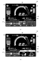
- (b) The display screen in the display device of the combine which is the working machine of one Embodiment which concerns on this invention The figure which shows the state by which the interruption display screen was displayed.
- the work machine provided with the display device 27 is not limited to the present embodiment, and may be a work machine such as a tractor or a backhoe.
- the combine 1 includes a traveling unit 2, a cutting unit 5 as a working device, a threshing unit 9, a sorting unit 10, a grain storage unit 11, and a maneuvering unit.
- a unit 14 and the like are provided.
- the traveling unit 2 travels the aircraft in the forward or reverse direction.
- the traveling unit 2 is provided in the lower part of the body frame 3.
- the traveling unit 2 includes a crawler traveling device 4 having a pair of left and right crawlers.
- the traveling unit 2 is provided with a traveling speed sensor 20 that detects the traveling speed of the aircraft (see FIG. 2).
- the mowing unit 5 is for harvesting cereal grains in the field.
- the cutting unit 5 is provided at the front end of the machine body frame 3 (front part of the machine body) so as to be movable up and down with respect to the machine body.
- the reaping unit 5 causes the culm in the field to be caused by the pulling device 6, cuts the root of the culm after the pulling by the cutting device 7, and conveys the cut culm to the threshing unit 9 side by the cutting device 8. Configured.
- the threshing unit 9 threshs the cereal.
- the threshing unit 9 is provided on the left front side of the machine body frame 3 and behind the cutting unit 5.
- the threshing unit 9 is configured to inherit the cereals conveyed from the cutting unit 5, thresh the cereals being conveyed by the handling cylinder and the like, and drop the threshing processed product to the sorting unit 10.
- the threshing section 9 is provided with a threshing section load sensor 24 that detects the load of the threshing section 9 (see FIG. 2).
- the sorting unit 10 sorts cereals into grains and wastes.
- the sorting unit 10 is provided on the left side of the machine body frame 3 and below the threshing unit 9.
- the sorting unit 10 sorts the processed material dropped from the threshing unit 9 into grains, spiked grains, unthreshed grains, waste, dust, and the like by a rocking sorter and a wind sorter using a rocking sorter.
- the sorting unit 10 is configured to convey the selected grain to the grain storage unit 11, to carry the spiked grains and the unthreshed grains to the threshing unit 9, and to discharge waste and dust to the outside. .
- the sorting unit 10 is provided with a sorting unit load sensor 25 that detects the load of the sorting unit 10 (see FIG. 2).
- Kernel storage unit 11 stores threshed and selected kernels.
- the grain storage unit 11 is provided on the right side of the machine body frame 3 on the right side of the threshing unit 9 and the sorting unit 10.
- the grain storage unit 11 includes a Glen tank 12, a grain discharging device 13, and the like.
- the grain storage unit 11 stores the grain conveyed from the sorting unit 10 in the grain tank 12 and discharges the grain stored in the grain tank 12 to the outside of the machine body by the grain discharging device 13. Composed.
- the Glen tank 12 is provided with a weight sensor 23 for detecting the amount of stored grain (see FIG. 2).
- the steering unit 14 is operated by the operator.
- the control unit 14 is provided on the right front side of the body frame 3 and on the right side of the cutting unit 5.
- an operation tool 17 for operating the combine 1 and a display device 27 are arranged around the cockpit 16 in the cabin 15.
- the operation tool 17 includes an operation tool that adjusts the left and right height and the front and rear height of the combine 1, and an operation tool that operates each working device such as the cutting unit 5 and the threshing unit 9.
- the operation tool 17 includes an operation amount detection sensor 17a that detects an operation amount of each operation tool.
- ECU19 (refer FIG. 2) which controls the engine 18 and each work apparatus with the signal from the operation amount detection sensor 17a is provided.
- the ECU 19 controls the engine 18 and various working devices.
- the ECU 19 stores various programs for controlling the engine 18, each work device, and the like. Further, the ECU 19 can perform predetermined calculations according to these programs and the like, and can store the results of the calculations.
- the ECU 19 may actually be configured such that a CPU, ROM, RAM, HDD, or the like is connected by a bus, or may be configured by a one-chip LSI or the like.
- the ECU 19 is connected to the traveling speed sensor 20 of the airframe and the rotational speed sensor 21 of the engine 18, and can acquire the traveling speed detected by the traveling speed sensor 20 and the rotational speed sensor 21 and the rotational speed of the engine 18. It is.
- the ECU 19 is connected to the fuel fuel gauge 22 and can acquire the fuel remaining quantity in a fuel tank (not shown) detected by the fuel fuel gauge 22.
- ECU19 is connected to the weight sensor 23 of the Glen tank 12, and can acquire the signal from the weight sensor 23 of the Glen tank 12.
- the weight sensor 23 detects the internal capacity of the glen tank 12, but the present invention is not limited to this, and any apparatus capable of detecting the internal capacity may be used.
- the ECU 19 is connected to the threshing part load sensor 24 and the sorting part load sensor 25, and can acquire signals from the threshing part load sensor 24 and the sorting part load sensor 25.
- the ECU 19 is connected to the transmission 26 and can acquire a signal from the transmission 26.
- the ECU 19 is connected to the engine 18 (not shown various sensors and fuel injection devices provided in the engine 18), and can acquire signals from various sensors and control the engine 18.
- ECU19 is connected to the control apparatus 29 of the display apparatus 27, and can acquire various signals from the control apparatus 29.
- the ECU 19 is connected to the operation amount detection sensor 17a and can acquire a signal from the operation amount detection sensor 17a.
- the combine 1 transmits the power of the engine 18 to each working device by operating the operation tool in the control unit 14, and the harvesting unit 5 harvests the grain culm while the traveling unit 2 travels the machine body.
- the threshing unit 9 threshs the grain from the reaping unit 5, the sorting unit 10 sorts the processed product from the threshing unit 9, and the grain storage unit 11 stores the grain from the sorting unit 10 and threshing at the same time. It is comprised so that the waste from the part 9 can be discharged
- the display device 27 displays various information related to the combine 1.
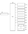
- the display device 27 includes a liquid crystal display 28 and a control device 29.
- the liquid crystal display 28 is disposed at a position where the liquid crystal display 28 is visible and operable when the operator sits on the cockpit 16 of the control unit 14 (see FIG. 1).
- the display device 27 is configured to be able to display corresponding graphics based on various signals transmitted from the control device 29.
- the liquid crystal display 28 displays characters and figures in accordance with transmitted signals and inputs signals.
- the liquid crystal display 28 may be composed of a touch panel that displays characters and figures and can input signals by touching the screen.
- the liquid crystal display 28 is configured to be able to display a traveling speed, a rotational speed of the engine 18, a grain storage amount, a fuel remaining amount, a threshing portion load, a sorting portion load, an operation time, a shift display, and various alarms. Note that the characters and graphics displayed on the display screen 30 of the liquid crystal display 28 are not limited to those in the present embodiment.
- a traveling speed meter 31 in which the traveling speed is displayed as a numerical value is arranged.
- a rotation speed meter 32 that displays the rotation speed of the engine 18 is disposed above the traveling speed meter 31 on the display screen 30.
- the tachometer 32 is configured by a figure imitating an arc-shaped meter.
- a grain storage meter 33 On the left side of the display screen 30, a grain storage meter 33 on which the grain storage amount of the Glen tank 12 is displayed is arranged.
- the grain storage meter 33 is configured by adding a unit scale serving as a reference to a figure imitating the Glen tank 12.
- a fuel remaining amount meter 34 for displaying the fuel remaining amount is arranged on the right side of the display screen 30, a fuel remaining amount meter 34 for displaying the fuel remaining amount is arranged.
- the fuel fuel gauge 34 is configured by adding a unit scale serving as a reference to a figure imitating a level gauge in the same manner as the grain reservoir 33.
- a threshing monitor 35 and a sorting monitor 36 are arranged below the traveling speed meter 31 on the display screen 30, a threshing monitor 35 and a sorting monitor 36 are arranged.
- the threshing monitor 35 is configured such that a predetermined area can be displayed in a predetermined display color.
- the sorting monitor 36 is configured to display a predetermined area in a predetermined display color.
- an information display area 37 for displaying the operation time, the state of the transmission 26, and various alarms in numerical values and characters is arranged below the threshing monitor 35 and the sorting monitor 36 on the display screen 30, an information display area 37 for displaying the operation time, the state of the transmission 26, and various alarms in numerical values and characters is arranged.
- the liquid crystal display 28 is connected to the control device 29 and relates to the running speed, rotation speed, grain storage amount, fuel remaining amount, threshing portion load, sorting portion load, operation time, speed change display, and various alarms from the control device 29. It is possible to acquire a signal.
- the control device 29 controls the liquid crystal display 28.
- the control device 29 is configured integrally with or separate from the liquid crystal display 28 or the ECU 19.
- the control device 29 stores various programs for controlling the liquid crystal display 28.
- the control device 29 can perform a predetermined calculation according to these programs and the like, and can store the result of the calculation.
- the control device 29 may actually be configured such that a CPU, ROM, RAM, HDD, or the like is connected by a bus, or may be configured by a one-chip LSI or the like.
- the control device 29 is connected to the ECU 19 and acquires signals from the ECU 19 regarding travel speed, rotation speed, grain storage amount, fuel remaining amount, threshing portion load, sorting portion load, operation time, shift display, and various alarms. It is possible.
- the control device 29 controls the liquid crystal display 28 based on signals relating to the traveling speed, rotational speed, grain storage amount, fuel remaining amount, threshing portion load, sorting portion load, operation time, shift display, and various alarms from the ECU 19. It is possible to display predetermined characters and figures. Further, the control device 29 can acquire various signals input from the liquid crystal display 28. That is, the control device 29 can display information about the combine 1 on the liquid crystal display 28 based on various signals, and can transmit an input signal from the liquid crystal display 28 to the ECU 19.
- the control device 29 obtains signals related to travel speed, rotational speed, grain storage amount, fuel remaining amount, threshing portion load, sorting portion load, operation time, shift display, and various alarms from the ECU 19. Then, based on the signal, a signal is transmitted so as to display a predetermined character or figure on the liquid crystal display 28.
- the traveling speed meter 31 of the liquid crystal display 28 displays the traveling speed as a numerical value based on a signal related to the traveling speed acquired from the ECU 19.
- the rotation speed is displayed by lighting the corresponding scale portion with a predetermined display color based on the signal regarding the rotation speed acquired from the ECU 19.
- the grain storage amount is displayed by lighting a figure of a predetermined display color between the corresponding unit scales based on a signal related to the grain storage amount acquired from the ECU 19. Is done.
- the fuel remaining amount indicator 34 of the liquid crystal display 28 displays the fuel remaining amount by lighting a figure of a predetermined display color between the corresponding unit scales based on a signal related to the fuel remaining amount acquired from the ECU 19. .
- the threshing portion load is displayed by lighting a figure of a predetermined display color in the corresponding area based on the signal regarding the threshing portion load acquired from the ECU 19.
- the sorting monitor 36 of the liquid crystal display 28 displays the sorting unit load by lighting a figure of a predetermined display color in a corresponding area based on a signal related to the sorting unit load acquired from the ECU 19.
- predetermined information is displayed in the information display area 37 by numerical values and characters based on the operation time acquired from the ECU 19, the state of the transmission 26, and various alarm signals.
- the control device 29 via the ECU 19, travel speed, rotation speed, grain storage amount, fuel remaining amount, threshing portion load, sorting portion load, operation time, shift display, and various Get a warning signal.
- the control device 29 includes a traveling speed meter 31, a rotational speed meter 32, a grain storage meter 33, a fuel remaining amount meter 34, a threshing monitor 35, a sorting monitor 36, and an information display area. A predetermined figure is turned on at 37.
- a signal from the operation amount detection sensor 17a is transmitted to the control device 29 (see FIG. 2).
- the control device 29 determines that the operation tool 17 related to the forward / backward posture or the left / right posture of the combine 1 has been operated, and displays the display screen.
- the interrupt display screen 38 is displayed as an interrupt at 30. The same applies to the vertical orientation (distance between the aircraft and the ground).
- the interrupt display screen 38 is composed of a substantially rectangular screen that is sufficiently smaller than the display screen. On the interrupt display screen 38, information on the posture of the combine 1 is displayed. Specifically, the interrupt display screen 38 displays the current setting value for the forward / backward posture of the combine 1 and the current setting value for the horizontal posture of the combine 1.
- the control device 29 causes the interrupt display screen 38 to be interrupted and displayed on a portion of the display screen 30 where information that the operator does not need immediately in the operation of the combine 1 is displayed.
- the control device 29 displays the interrupt display screen 38 in a portion of the information display area 37 of the display screen 30 where the time and warning are displayed.
- the control device 29 causes the interrupt display screen 38 to be displayed so as to be superimposed on a portion of the information display area 37 where the time and warning are displayed.
- the operator can easily recognize that the interrupt display screen 38 is displayed on the display screen 30. Further, the operator can acquire information about the adjustment of the combine 1 posture from the interrupt display screen 38 while continuously acquiring information necessary for the operation of the combine 1 from the display screen 30.
- the control device 29 interrupts and displays the interrupt display screen 38 while determining that the operation tool 17 relating to the front-rear direction posture or the left-right direction posture is being operated based on the signal from the operation amount detection sensor 17 a.
- the control device 29 determines that the operation of the operation tool 17 related to the front-rear direction posture or the left-right direction posture is finished due to the stop of the signal from the operation amount detection sensor 17a, the control device 29 coincides with the end of the operation or for a predetermined time from the end of the operation.
- the interrupt display screen 38 is deleted. That is, the control device 29 displays the time and warning in the information display area 37 again at the same time as the operation is completed or after a predetermined time has elapsed since the operation was completed.
- the control device 29 determines that the operation tool 17 related to the front-rear direction posture or the left-right direction posture is operated based on a signal from the operation amount detection sensor 17 a, after a predetermined time has elapsed.
- the interrupt display screen 38 is deleted.
- the control device 29 displays the time and warning in the information display area 37 again after a predetermined time has elapsed since the start of posture adjustment.
- the control device 29 determines that the operation tool 17 related to each work device of the combine 1 has been operated based on a signal from the operation amount detection sensor 17a acquired via the ECU 19, an interrupt display is displayed on the display screen 30.
- the screen 38 is interrupted and displayed. At this time, the interrupt display screen 38 displays the current set value for the work device on which the combine 1 is operated.
- the harvester 5 and the threshing portion that are the combine 1 or the work device included in the combine 1 When a predetermined operation is performed on 9 or the like, information on the combine 1 or the reaping unit 5, the threshing unit 9 or the like is displayed via an interrupt display screen 38 which is an embodiment of the interrupt display.
- an interrupt display screen 38 which is an embodiment of the interrupt display.
- the information on the setting of the posture of the combine 1 or the mowing unit 5 and the threshing unit 9 is set as the predetermined operation by adjusting the posture of the combine 1 or operating the operating tool 17 such as the operation of the mowing unit 5 and the threshing unit 9.
- the information about the settings such as these is displayed via an interrupt display screen 38 which is a form of interrupt display.
- position of the combine 1 and operation of each working device is performed is demonstrated.
- the present invention is not limited to this, and any information that is not displayed on the current display screen 30 of the display device 27 may be displayed by transmitting a signal by operating the operation tool 17.
- the present invention can be used in the technology of display devices for work machines.
Landscapes
- Engineering & Computer Science (AREA)
- Life Sciences & Earth Sciences (AREA)
- Environmental Sciences (AREA)
- Mechanical Engineering (AREA)
- General Physics & Mathematics (AREA)
- Physics & Mathematics (AREA)
- Computer Hardware Design (AREA)
- Theoretical Computer Science (AREA)
- Transportation (AREA)
- Combustion & Propulsion (AREA)
- Chemical & Material Sciences (AREA)
- Soil Sciences (AREA)
- Combines (AREA)
- Harvester Elements (AREA)
Abstract
Description
このように構成することにより、所定の操作に伴ってその操作に必要な情報が割り込み表示される。これにより、情報の取得を意識することなくコンバイン1または刈取部5、脱穀部9等の操作具17の操作時に必要な情報を必要な時に取得することができる。
このように構成することにより、コンバイン1の姿勢の調整または刈取部5、脱穀部9等の操作に必要な情報が割り込み表示される。これにより、情報の取得を意識することなくコンバイン1または刈取部5、脱穀部9等の操作具17の操作時に必要な情報を必要な時に取得することができる。
5 刈取部
9 脱穀部
30 表示画面
38 割り込み表示画面
Claims (2)
- 表示画面に任意の情報を割り込み表示可能な作業機の表示装置において、
作業機または作業機が具備する作業装置について所定の操作が行われると作業機または作業装置についての情報が割り込み表示される作業機の表示装置。 - 前記作業機の姿勢の調整または前記作業装置の操作を前記所定の操作として、作業機の姿勢の設定についての情報または作業装置の設定についての情報が割り込み表示される請求項1に記載の作業機の表示装置。
Priority Applications (5)
| Application Number | Priority Date | Filing Date | Title |
|---|---|---|---|
| US14/776,144 US20160035319A1 (en) | 2013-03-13 | 2014-02-24 | Display device for work machines |
| CN201480016309.8A CN105188345A (zh) | 2013-03-13 | 2014-02-24 | 作业机械的显示装置 |
| KR1020157027725A KR20150121240A (ko) | 2013-03-13 | 2014-02-24 | 작업기의 표시 장치 |
| AU2014232043A AU2014232043A1 (en) | 2013-03-13 | 2014-02-24 | Display device for work machines |
| EP14765252.3A EP2974588A4 (en) | 2013-03-13 | 2014-02-24 | DISPLAY DEVICE FOR WORK MACHINES |
Applications Claiming Priority (2)
| Application Number | Priority Date | Filing Date | Title |
|---|---|---|---|
| JP2013-050742 | 2013-03-13 | ||
| JP2013050742A JP6073714B2 (ja) | 2013-03-13 | 2013-03-13 | 作業機の表示装置 |
Publications (1)
| Publication Number | Publication Date |
|---|---|
| WO2014141860A1 true WO2014141860A1 (ja) | 2014-09-18 |
Family
ID=51536535
Family Applications (1)
| Application Number | Title | Priority Date | Filing Date |
|---|---|---|---|
| PCT/JP2014/054275 Ceased WO2014141860A1 (ja) | 2013-03-13 | 2014-02-24 | 作業機の表示装置 |
Country Status (7)
| Country | Link |
|---|---|
| US (1) | US20160035319A1 (ja) |
| EP (1) | EP2974588A4 (ja) |
| JP (1) | JP6073714B2 (ja) |
| KR (1) | KR20150121240A (ja) |
| CN (1) | CN105188345A (ja) |
| AU (1) | AU2014232043A1 (ja) |
| WO (1) | WO2014141860A1 (ja) |
Families Citing this family (11)
| Publication number | Priority date | Publication date | Assignee | Title |
|---|---|---|---|---|
| KR102234179B1 (ko) | 2013-03-27 | 2021-03-31 | 가부시끼 가이샤 구보다 | 콤바인 |
| JP6403056B2 (ja) * | 2014-10-16 | 2018-10-10 | ヤンマー株式会社 | 作業車両 |
| US20170115833A1 (en) * | 2015-10-27 | 2017-04-27 | Cnh Industrial America Llc | Top bar display for an agricultural system |
| US10667033B2 (en) * | 2016-03-02 | 2020-05-26 | Bragi GmbH | Multifactorial unlocking function for smart wearable device and method |
| KR102493704B1 (ko) | 2017-06-26 | 2023-02-01 | 가부시끼 가이샤 구보다 | 작업기에 구비되는 표시 장치 및 당해 표시 장치가 구비된 콤바인 |
| KR102566904B1 (ko) | 2017-06-26 | 2023-08-16 | 가부시끼 가이샤 구보다 | 작업기에 구비되는 표시 장치 |
| JP7190804B2 (ja) * | 2017-06-26 | 2022-12-16 | 株式会社クボタ | 作業機に備えられる表示装置 |
| KR102493811B1 (ko) | 2017-06-26 | 2023-02-01 | 가부시끼 가이샤 구보다 | 작업기에 구비되는 표시 장치 및 해당 표시 장치가 구비된 콤바인 |
| KR102530375B1 (ko) * | 2017-06-26 | 2023-05-09 | 가부시끼 가이샤 구보다 | 작업기에 구비되는 표시 장치 |
| KR102557234B1 (ko) * | 2018-01-23 | 2023-07-20 | 가부시끼 가이샤 구보다 | 표시 장치 및 해당 표시 장치가 구비된 콤바인 |
| US11042280B2 (en) * | 2018-03-05 | 2021-06-22 | Agco Corporation | Harvesting machine with visualization system |
Citations (6)
| Publication number | Priority date | Publication date | Assignee | Title |
|---|---|---|---|---|
| JPH05338467A (ja) * | 1992-06-12 | 1993-12-21 | Iseki & Co Ltd | トラクタ等のメータパネル |
| JPH06316228A (ja) * | 1993-05-07 | 1994-11-15 | Iseki & Co Ltd | トラクタのモニター装置 |
| JP2004248621A (ja) * | 2003-02-21 | 2004-09-09 | Iseki & Co Ltd | 作業車両の設定装置 |
| JP2005081968A (ja) * | 2003-09-08 | 2005-03-31 | Yanmar Co Ltd | 作業車両の制御装置 |
| JP2011188814A (ja) * | 2010-03-15 | 2011-09-29 | Iseki & Co Ltd | コンバインのモニタ表示装置 |
| JP2011231488A (ja) | 2010-04-26 | 2011-11-17 | Hitachi Constr Mach Co Ltd | 建設機械の表示装置 |
Family Cites Families (7)
| Publication number | Priority date | Publication date | Assignee | Title |
|---|---|---|---|---|
| JP2003159959A (ja) * | 2001-11-22 | 2003-06-03 | Yanmar Agricult Equip Co Ltd | 作業機における表示装置 |
| CN2631822Y (zh) * | 2003-07-09 | 2004-08-11 | 中国一拖集团有限公司 | 农业车辆数字仪表装置 |
| DE102005003920B4 (de) * | 2004-01-28 | 2017-01-26 | Yazaki Corporation | Anzeigeeinheit |
| CN2685136Y (zh) * | 2004-02-13 | 2005-03-16 | 江苏瑞通信息产业有限公司 | 汽车电子液晶智能组合仪表盘 |
| JP4613041B2 (ja) * | 2004-09-27 | 2011-01-12 | 日立建機株式会社 | 作業機の表示装置 |
| DE102007022899A1 (de) * | 2007-05-14 | 2008-11-20 | Claas Selbstfahrende Erntemaschinen Gmbh | Landwirtschaftliche Arbeitsmaschine |
| CN101318473A (zh) * | 2008-05-22 | 2008-12-10 | 中国科学院电工研究所 | 一种混合动力车综合仪表系统 |
-
2013
- 2013-03-13 JP JP2013050742A patent/JP6073714B2/ja active Active
-
2014
- 2014-02-24 WO PCT/JP2014/054275 patent/WO2014141860A1/ja not_active Ceased
- 2014-02-24 KR KR1020157027725A patent/KR20150121240A/ko not_active Ceased
- 2014-02-24 EP EP14765252.3A patent/EP2974588A4/en not_active Ceased
- 2014-02-24 AU AU2014232043A patent/AU2014232043A1/en not_active Abandoned
- 2014-02-24 CN CN201480016309.8A patent/CN105188345A/zh active Pending
- 2014-02-24 US US14/776,144 patent/US20160035319A1/en not_active Abandoned
Patent Citations (6)
| Publication number | Priority date | Publication date | Assignee | Title |
|---|---|---|---|---|
| JPH05338467A (ja) * | 1992-06-12 | 1993-12-21 | Iseki & Co Ltd | トラクタ等のメータパネル |
| JPH06316228A (ja) * | 1993-05-07 | 1994-11-15 | Iseki & Co Ltd | トラクタのモニター装置 |
| JP2004248621A (ja) * | 2003-02-21 | 2004-09-09 | Iseki & Co Ltd | 作業車両の設定装置 |
| JP2005081968A (ja) * | 2003-09-08 | 2005-03-31 | Yanmar Co Ltd | 作業車両の制御装置 |
| JP2011188814A (ja) * | 2010-03-15 | 2011-09-29 | Iseki & Co Ltd | コンバインのモニタ表示装置 |
| JP2011231488A (ja) | 2010-04-26 | 2011-11-17 | Hitachi Constr Mach Co Ltd | 建設機械の表示装置 |
Non-Patent Citations (1)
| Title |
|---|
| See also references of EP2974588A4 |
Also Published As
| Publication number | Publication date |
|---|---|
| KR20150121240A (ko) | 2015-10-28 |
| EP2974588A4 (en) | 2016-11-23 |
| EP2974588A1 (en) | 2016-01-20 |
| CN105188345A (zh) | 2015-12-23 |
| JP6073714B2 (ja) | 2017-02-01 |
| US20160035319A1 (en) | 2016-02-04 |
| AU2014232043A1 (en) | 2015-10-22 |
| JP2014176315A (ja) | 2014-09-25 |
Similar Documents
| Publication | Publication Date | Title |
|---|---|---|
| JP6073714B2 (ja) | 作業機の表示装置 | |
| EP3718392A1 (en) | Harvester | |
| JP2017018014A (ja) | コンバイン | |
| WO2014141850A1 (ja) | エンジン作業機の表示装置 | |
| JP2014177764A (ja) | 作業機の表示装置 | |
| JP2019110781A (ja) | 収穫機制御システム | |
| JP7034732B2 (ja) | 作業機に備えられる表示装置及び該表示装置が備えられたコンバイン | |
| JP2018078820A (ja) | 収量分布算出装置及び収量分布算出プログラム | |
| JP2019170192A (ja) | コンバイン | |
| JP2019126287A (ja) | 表示装置及び該表示装置が備えられたコンバイン | |
| WO2014141848A1 (ja) | 作業機の表示装置 | |
| JP2005080549A (ja) | コンバインにおける制御装置 | |
| JP2005168324A (ja) | コンバインのモニタ装置 | |
| JP2009254280A (ja) | コンバインのモニタ表示装置 | |
| JP5486337B2 (ja) | コンバイン | |
| JP2015096044A (ja) | 作業機の表示装置 | |
| JP6827374B2 (ja) | 作業機に備えられる表示装置及び該表示装置が備えられたコンバイン | |
| KR102557234B1 (ko) | 표시 장치 및 해당 표시 장치가 구비된 콤바인 | |
| JP2006141250A (ja) | コンバイン | |
| JP2014176313A (ja) | 作業機の表示装置 | |
| JP6748869B2 (ja) | コンバイン | |
| JP2017100465A (ja) | 作業車両 | |
| JP2014218170A (ja) | エンジン作業機の表示装置 | |
| JP2014150755A (ja) | コンバインの穀粒排出装置 | |
| JP7260502B2 (ja) | 情報提示装置、遠隔操作システムおよびプログラム |
Legal Events
| Date | Code | Title | Description |
|---|---|---|---|
| WWE | Wipo information: entry into national phase |
Ref document number: 201480016309.8 Country of ref document: CN |
|
| 121 | Ep: the epo has been informed by wipo that ep was designated in this application |
Ref document number: 14765252 Country of ref document: EP Kind code of ref document: A1 |
|
| DPE1 | Request for preliminary examination filed after expiration of 19th month from priority date (pct application filed from 20040101) | ||
| NENP | Non-entry into the national phase |
Ref country code: DE |
|
| WWE | Wipo information: entry into national phase |
Ref document number: 14776144 Country of ref document: US |
|
| WWE | Wipo information: entry into national phase |
Ref document number: 2014765252 Country of ref document: EP |
|
| ENP | Entry into the national phase |
Ref document number: 20157027725 Country of ref document: KR Kind code of ref document: A |
|
| ENP | Entry into the national phase |
Ref document number: 2014232043 Country of ref document: AU Date of ref document: 20140224 Kind code of ref document: A |