WO2014141861A1 - マイクロ流路装置及びこれに関する方法 - Google Patents
マイクロ流路装置及びこれに関する方法 Download PDFInfo
- Publication number
- WO2014141861A1 WO2014141861A1 PCT/JP2014/054299 JP2014054299W WO2014141861A1 WO 2014141861 A1 WO2014141861 A1 WO 2014141861A1 JP 2014054299 W JP2014054299 W JP 2014054299W WO 2014141861 A1 WO2014141861 A1 WO 2014141861A1
- Authority
- WO
- WIPO (PCT)
- Prior art keywords
- upstream
- liquid
- downstream
- liquid plug
- plug
- Prior art date
- Legal status (The legal status is an assumption and is not a legal conclusion. Google has not performed a legal analysis and makes no representation as to the accuracy of the status listed.)
- Ceased
Links
Images






Classifications
-
- C—CHEMISTRY; METALLURGY
- C12—BIOCHEMISTRY; BEER; SPIRITS; WINE; VINEGAR; MICROBIOLOGY; ENZYMOLOGY; MUTATION OR GENETIC ENGINEERING
- C12M—APPARATUS FOR ENZYMOLOGY OR MICROBIOLOGY; APPARATUS FOR CULTURING MICROORGANISMS FOR PRODUCING BIOMASS, FOR GROWING CELLS OR FOR OBTAINING FERMENTATION OR METABOLIC PRODUCTS, i.e. BIOREACTORS OR FERMENTERS
- C12M23/00—Constructional details, e.g. recesses, hinges
- C12M23/02—Form or structure of the vessel
- C12M23/16—Microfluidic devices; Capillary tubes
-
- B—PERFORMING OPERATIONS; TRANSPORTING
- B01—PHYSICAL OR CHEMICAL PROCESSES OR APPARATUS IN GENERAL
- B01F—MIXING, e.g. DISSOLVING, EMULSIFYING OR DISPERSING
- B01F23/00—Mixing according to the phases to be mixed, e.g. dispersing or emulsifying
- B01F23/40—Mixing liquids with liquids; Emulsifying
- B01F23/405—Methods of mixing liquids with liquids
-
- B—PERFORMING OPERATIONS; TRANSPORTING
- B01—PHYSICAL OR CHEMICAL PROCESSES OR APPARATUS IN GENERAL
- B01F—MIXING, e.g. DISSOLVING, EMULSIFYING OR DISPERSING
- B01F25/00—Flow mixers; Mixers for falling materials, e.g. solid particles
- B01F25/14—Mixing drops, droplets or bodies of liquid which flow together or contact each other
-
- B—PERFORMING OPERATIONS; TRANSPORTING
- B01—PHYSICAL OR CHEMICAL PROCESSES OR APPARATUS IN GENERAL
- B01F—MIXING, e.g. DISSOLVING, EMULSIFYING OR DISPERSING
- B01F33/00—Other mixers; Mixing plants; Combinations of mixers
- B01F33/30—Micromixers
- B01F33/301—Micromixers using specific means for arranging the streams to be mixed, e.g. channel geometries or dispositions
-
- B—PERFORMING OPERATIONS; TRANSPORTING
- B01—PHYSICAL OR CHEMICAL PROCESSES OR APPARATUS IN GENERAL
- B01F—MIXING, e.g. DISSOLVING, EMULSIFYING OR DISPERSING
- B01F33/00—Other mixers; Mixing plants; Combinations of mixers
- B01F33/30—Micromixers
- B01F33/302—Micromixers the materials to be mixed flowing in the form of droplets
-
- B—PERFORMING OPERATIONS; TRANSPORTING
- B01—PHYSICAL OR CHEMICAL PROCESSES OR APPARATUS IN GENERAL
- B01F—MIXING, e.g. DISSOLVING, EMULSIFYING OR DISPERSING
- B01F33/00—Other mixers; Mixing plants; Combinations of mixers
- B01F33/30—Micromixers
- B01F33/302—Micromixers the materials to be mixed flowing in the form of droplets
- B01F33/3021—Micromixers the materials to be mixed flowing in the form of droplets the components to be mixed being combined in a single independent droplet, e.g. these droplets being divided by a non-miscible fluid or consisting of independent droplets
-
- B—PERFORMING OPERATIONS; TRANSPORTING
- B01—PHYSICAL OR CHEMICAL PROCESSES OR APPARATUS IN GENERAL
- B01F—MIXING, e.g. DISSOLVING, EMULSIFYING OR DISPERSING
- B01F33/00—Other mixers; Mixing plants; Combinations of mixers
- B01F33/30—Micromixers
- B01F33/302—Micromixers the materials to be mixed flowing in the form of droplets
- B01F33/3022—Micromixers the materials to be mixed flowing in the form of droplets the components being formed by independent droplets which are alternated, the mixing of the components being achieved by diffusion between droplets
-
- B—PERFORMING OPERATIONS; TRANSPORTING
- B01—PHYSICAL OR CHEMICAL PROCESSES OR APPARATUS IN GENERAL
- B01L—CHEMICAL OR PHYSICAL LABORATORY APPARATUS FOR GENERAL USE
- B01L3/00—Containers or dishes for laboratory use, e.g. laboratory glassware; Droppers
- B01L3/02—Burettes; Pipettes
- B01L3/0289—Apparatus for withdrawing or distributing predetermined quantities of fluid
- B01L3/0293—Apparatus for withdrawing or distributing predetermined quantities of fluid for liquids
-
- B—PERFORMING OPERATIONS; TRANSPORTING
- B01—PHYSICAL OR CHEMICAL PROCESSES OR APPARATUS IN GENERAL
- B01L—CHEMICAL OR PHYSICAL LABORATORY APPARATUS FOR GENERAL USE
- B01L3/00—Containers or dishes for laboratory use, e.g. laboratory glassware; Droppers
- B01L3/50—Containers for the purpose of retaining a material to be analysed, e.g. test tubes
- B01L3/502—Containers for the purpose of retaining a material to be analysed, e.g. test tubes with fluid transport, e.g. in multi-compartment structures
- B01L3/5027—Containers for the purpose of retaining a material to be analysed, e.g. test tubes with fluid transport, e.g. in multi-compartment structures by integrated microfluidic structures, i.e. dimensions of channels and chambers are such that surface tension forces are important, e.g. lab-on-a-chip
-
- B—PERFORMING OPERATIONS; TRANSPORTING
- B01—PHYSICAL OR CHEMICAL PROCESSES OR APPARATUS IN GENERAL
- B01L—CHEMICAL OR PHYSICAL LABORATORY APPARATUS FOR GENERAL USE
- B01L3/00—Containers or dishes for laboratory use, e.g. laboratory glassware; Droppers
- B01L3/50—Containers for the purpose of retaining a material to be analysed, e.g. test tubes
- B01L3/502—Containers for the purpose of retaining a material to be analysed, e.g. test tubes with fluid transport, e.g. in multi-compartment structures
- B01L3/5027—Containers for the purpose of retaining a material to be analysed, e.g. test tubes with fluid transport, e.g. in multi-compartment structures by integrated microfluidic structures, i.e. dimensions of channels and chambers are such that surface tension forces are important, e.g. lab-on-a-chip
- B01L3/502769—Containers for the purpose of retaining a material to be analysed, e.g. test tubes with fluid transport, e.g. in multi-compartment structures by integrated microfluidic structures, i.e. dimensions of channels and chambers are such that surface tension forces are important, e.g. lab-on-a-chip characterised by multiphase flow arrangements
- B01L3/502784—Containers for the purpose of retaining a material to be analysed, e.g. test tubes with fluid transport, e.g. in multi-compartment structures by integrated microfluidic structures, i.e. dimensions of channels and chambers are such that surface tension forces are important, e.g. lab-on-a-chip characterised by multiphase flow arrangements specially adapted for droplet or plug flow, e.g. digital microfluidics
-
- B—PERFORMING OPERATIONS; TRANSPORTING
- B01—PHYSICAL OR CHEMICAL PROCESSES OR APPARATUS IN GENERAL
- B01L—CHEMICAL OR PHYSICAL LABORATORY APPARATUS FOR GENERAL USE
- B01L3/00—Containers or dishes for laboratory use, e.g. laboratory glassware; Droppers
- B01L3/50—Containers for the purpose of retaining a material to be analysed, e.g. test tubes
- B01L3/502—Containers for the purpose of retaining a material to be analysed, e.g. test tubes with fluid transport, e.g. in multi-compartment structures
- B01L3/5027—Containers for the purpose of retaining a material to be analysed, e.g. test tubes with fluid transport, e.g. in multi-compartment structures by integrated microfluidic structures, i.e. dimensions of channels and chambers are such that surface tension forces are important, e.g. lab-on-a-chip
- B01L3/502769—Containers for the purpose of retaining a material to be analysed, e.g. test tubes with fluid transport, e.g. in multi-compartment structures by integrated microfluidic structures, i.e. dimensions of channels and chambers are such that surface tension forces are important, e.g. lab-on-a-chip characterised by multiphase flow arrangements
- B01L3/502784—Containers for the purpose of retaining a material to be analysed, e.g. test tubes with fluid transport, e.g. in multi-compartment structures by integrated microfluidic structures, i.e. dimensions of channels and chambers are such that surface tension forces are important, e.g. lab-on-a-chip characterised by multiphase flow arrangements specially adapted for droplet or plug flow, e.g. digital microfluidics
- B01L3/502792—Containers for the purpose of retaining a material to be analysed, e.g. test tubes with fluid transport, e.g. in multi-compartment structures by integrated microfluidic structures, i.e. dimensions of channels and chambers are such that surface tension forces are important, e.g. lab-on-a-chip characterised by multiphase flow arrangements specially adapted for droplet or plug flow, e.g. digital microfluidics for moving individual droplets on a plate, e.g. by locally altering surface tension
-
- G—PHYSICS
- G01—MEASURING; TESTING
- G01N—INVESTIGATING OR ANALYSING MATERIALS BY DETERMINING THEIR CHEMICAL OR PHYSICAL PROPERTIES
- G01N1/00—Sampling; Preparing specimens for investigation
- G01N1/28—Preparing specimens for investigation including physical details of (bio-)chemical methods covered elsewhere, e.g. G01N33/50, C12Q
- G01N1/38—Diluting, dispersing or mixing samples
-
- B—PERFORMING OPERATIONS; TRANSPORTING
- B01—PHYSICAL OR CHEMICAL PROCESSES OR APPARATUS IN GENERAL
- B01L—CHEMICAL OR PHYSICAL LABORATORY APPARATUS FOR GENERAL USE
- B01L2200/00—Solutions for specific problems relating to chemical or physical laboratory apparatus
- B01L2200/06—Fluid handling related problems
- B01L2200/0605—Metering of fluids
-
- B—PERFORMING OPERATIONS; TRANSPORTING
- B01—PHYSICAL OR CHEMICAL PROCESSES OR APPARATUS IN GENERAL
- B01L—CHEMICAL OR PHYSICAL LABORATORY APPARATUS FOR GENERAL USE
- B01L2200/00—Solutions for specific problems relating to chemical or physical laboratory apparatus
- B01L2200/06—Fluid handling related problems
- B01L2200/0621—Control of the sequence of chambers filled or emptied
-
- B—PERFORMING OPERATIONS; TRANSPORTING
- B01—PHYSICAL OR CHEMICAL PROCESSES OR APPARATUS IN GENERAL
- B01L—CHEMICAL OR PHYSICAL LABORATORY APPARATUS FOR GENERAL USE
- B01L2300/00—Additional constructional details
- B01L2300/08—Geometry, shape and general structure
- B01L2300/0861—Configuration of multiple channels and/or chambers in a single devices
- B01L2300/088—Channel loops
-
- B—PERFORMING OPERATIONS; TRANSPORTING
- B01—PHYSICAL OR CHEMICAL PROCESSES OR APPARATUS IN GENERAL
- B01L—CHEMICAL OR PHYSICAL LABORATORY APPARATUS FOR GENERAL USE
- B01L2400/00—Moving or stopping fluids
- B01L2400/06—Valves, specific forms thereof
- B01L2400/0688—Valves, specific forms thereof surface tension valves, capillary stop, capillary break
Definitions
- the present invention relates to a microchannel device and a method related thereto, and more particularly to effective operation of a trace amount liquid in the microchannel device.
- Patent Document 1 describes a cell culture apparatus in which at least two cell culture chambers having a channel structure in which cells are fixed and a culture medium is perfused are stacked.
- Non-Patent Document 1 and Non-Patent Document 2 describe a technique for flowing a liquid plug through a flow path of a micro flow path device.
- a stimulating substance for cell bodies (animal cells, microorganisms, etc.) is added to the chamber while maintaining a constant volume of the culture solution held in the cell culture chamber. It has been difficult to change the cell culture environment in the culture solution over time (for example, increasing the concentration of the stimulating substance in the culture solution stepwise).
- a stimulating substance when brought into contact with a cell body cultured in a small amount of culture medium in a cell culture chamber, the response of the cell body to the stimulating substance is evaluated. Furthermore, it was difficult to efficiently sample a small amount of the culture solution multiple times at short time intervals.
- the present invention has been made in view of the above problems, and an object of the present invention is to provide a microchannel device and a method related thereto that realize effective operation of a minute amount of liquid.
- a method according to an embodiment of the present invention for solving the above-described problem includes the following (a) to (g): (a) an upstream flow path section, a downstream flow path section, and A liquid holding portion provided between a downstream end portion of the upstream flow passage portion and an upstream end portion of the downstream flow passage portion; and the upstream end of the downstream flow passage portion from the downstream end portion of the upstream flow passage portion.
- a gas bypass channel part provided so as to bypass the liquid holding part up to a part; and (b) filling the gas in the gas bypass channel part with the gas, Holding a main liquid plug in the liquid holding part; (c) sequentially flowing a first upstream liquid plug and a second upstream liquid plug in the upstream flow path part toward the liquid holding part; ) By causing the first upstream liquid plug to flow into the liquid holding portion, the first Fusing an upstream liquid plug with the main liquid plug, and extruding a part of the fused main liquid plug to the downstream flow path; and (e) a gas following the first upstream fluid plug as the gas
- the one of the main liquid plugs pushed out by the step (d) is made to flow into the bypass channel and push a part of the gas in the gas bypass channel to the upstream end of the downstream channel.
- the method may further include the following (h): (h) collecting the first downstream liquid plug and the second downstream liquid plug.
- the second downstream liquid plug is formed in (g) within a time of less than 1 second from the formation of the first downstream liquid plug in (e).
- the first upstream liquid plug and the second upstream liquid plug may flow.
- the second upstream liquid plug is connected to the main liquid plug in (f) within a time of less than 1 second after the first upstream liquid plug is fused with the main liquid plug in (d).
- the first upstream liquid plug and the second upstream liquid plug may be allowed to flow in (c) so as to be fused.
- each volume of said 1st upstream liquid plug, said 2nd upstream liquid plug, said 1st downstream liquid plug, and said 2nd downstream liquid plug is good also as being less than 1 microliter.
- the main liquid plug held in the liquid holding part in (b) includes a first factor, and the first upstream liquid plug and the first flow in the upstream flow path part in (c).
- One or both of the two upstream liquid plugs may include a second factor that acts on the first factor.
- the first factor may be a cell body
- the second factor may be a substance that acts on the cell body.
- a microchannel device includes an upstream liquid plug and an upstream channel portion for flowing gas, and a downstream liquid plug and a downstream channel portion for flowing gas.
- a liquid holding portion for holding a main liquid plug provided between the downstream end portion of the upstream flow passage portion and the upstream end portion of the downstream flow passage portion, and the downstream end portion of the upstream flow passage portion.
- a gas bypass flow path section that is provided so as to bypass the liquid holding section to the upstream end of the downstream flow path section, and for flowing gas in a state where the liquid holding section holds the main liquid plug; It is characterized by having.
- ADVANTAGE OF THE INVENTION According to this invention, the microchannel apparatus which implement
- the upstream channel section, the liquid holding section, and the gas bypass channel section flow through the upstream channel section toward the liquid holding section that holds the main liquid plug.
- the upstream liquid plug flows into the liquid holding part without flowing into the gas bypass flow path part, and the gas flowing through the upstream flow path part toward the liquid holding part holding the main liquid plug is retained in the liquid. It is good also as providing so that it may flow in into the said gas bypass channel part, without flowing in into a part.
- the upstream channel portion, the liquid holding portion, and the gas bypass channel portion are filled with the gas, and the main liquid plug is filled in the liquid holding portion.
- the upstream liquid plug is moved from the upstream flow path portion to the gas bypass flow path portion. It is good also as providing so that the free energy change in the case of flowing in into may become large.
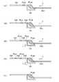
- FIG. 1 shows an example of a microchannel device 1 according to the present embodiment (hereinafter referred to as “the present device 1”).
- 2A and 2B show operations included in an example of a method according to the present embodiment (hereinafter referred to as “the present method”).
- the present apparatus 1 includes an upstream flow path portion 10 for flowing upstream liquid plugs PLu1, PLu2 and gases Gu1, Gu2, Gu3, downstream liquid plugs PLd1, PLd2 and gas.
- a main liquid plug PLm provided between the downstream flow path part 20 for flowing Gd1, Gd2, Gd3, the downstream end part 11 of the upstream flow path part 10 and the upstream end part 21 of the downstream flow path part 20 is provided.
- the method includes the following (a) to (g): (a) the upstream flow path section 10, the downstream flow path section 20, and the downstream of the upstream flow path section 10 A liquid holding portion 30 provided between the end portion 11 and the upstream end portion 21 of the downstream flow channel portion 20, and the upstream end of the downstream flow channel portion 20 from the downstream end portion 11 of the upstream flow channel portion 10.
- this device 1 including a gas-bypass channel portion 40 provided so as to bypass the liquid holding unit 30 up to the end portion 21; (b) the gas-bypass Filling the flow path part 40 with the gas Gb and holding the main liquid plug PLm in the liquid holding part 30; (c) the first upstream liquid plug PLu1 and the second upstream liquid in the upstream flow path part 10; Flowing the plug PLu2 sequentially toward the liquid holding unit 30; ) By causing the first upstream liquid plug PLu1 to flow into the liquid holding unit 30, the first upstream liquid plug PLu1 is fused with the main liquid plug PLm, and one of the main liquid plugs PLm after merging.
- the direction indicated by the arrow X indicates the direction in which the liquid and gas flow in the apparatus 1 (the same applies to other drawings). That is, the direction indicated by the arrow X is the downstream direction, and the direction opposite to the direction indicated by the arrow X is the upstream direction. Moreover, the arrow Y shown to FIG. 2A and 2B shows the gas flow in the gas bypass flow-path part 40 (it is the same also in another figure).
- the upstream flow path portion 10 of the apparatus 1 is a flow path through which the upstream liquid plugs PLu1 and PLu2 that flow into the liquid holding section 30 and the gases Gu1, Gu2, and Gu3 that flow into the gas bypass flow path section 40 flow.
- the upstream flow path section 10 is provided upstream of the liquid holding section 30 and is connected to the liquid holding section 30 at the downstream end 11 thereof.
- An upstream end 41 of the gas bypass channel 40 is opened at the downstream end 11 of the upstream channel 10.
- the downstream flow path unit 20 is a flow path through which the downstream liquid plugs PLd1, PLd2 formed from the main liquid plug PLm held in the liquid holding unit 30 and the gases Gd1, Gd2, Gd3 flowing out from the gas bypass flow path unit 40 flow. is there.
- the downstream flow path unit 20 is provided downstream of the liquid holding unit 30 and is connected to the liquid holding unit 30 at the upstream end 21 thereof.
- a downstream end 42 of the gas bypass channel 40 is opened at the upstream end 21 of the downstream channel 20.
- the liquid holding unit 30 is provided between the upstream channel unit 10 and the downstream channel unit 20. That is, the liquid holding unit 30 is provided between the downstream end portion 11 of the upstream flow path portion 10 and the upstream end portion 21 of the downstream flow path portion 20.
- the liquid holding unit 30 includes an upstream end 41 of the gas bypass channel 40 connected to the downstream end 11 of the upstream channel 10 (more specifically, the upstream channel 10.
- the downstream end of the gas bypass channel 40 connected to the upstream end 21 of the downstream channel 20 downstream of the upstream end 41 of the gas bypass channel 40 at the downstream end 11. It is provided upstream of the portion 42 (more specifically, the opening portion of the downstream end portion 42 of the gas bypass flow passage portion 40 in the upstream end portion 21 of the downstream flow passage portion 20). It can be said that the liquid holding unit 30 is an intermediate channel that connects the upstream channel unit 10 and the downstream channel unit 20 in the main channel including the upstream channel unit 10 and the downstream channel unit 20.
- the shape of the liquid holding part 30 is not particularly limited, for example, as shown in FIGS. It may be larger than the area and the cross-sectional area of the upstream end portion 21 of the downstream flow path portion 20.
- the gas bypass flow path section 40 allows the gas flowing through the upstream flow path section 10 to flow into the downstream flow path section 30 without flowing into the liquid holding section 30 while the liquid holding section 30 holds the main liquid plug PLm. It is a flow path for.
- the gas bypass flow path portion 40 bypasses the liquid holding portion 30 to allow the gas flowing in the upstream flow path portion 10 in a state where the liquid holding portion 30 holds the main liquid plug PLm, so that the downstream flow path portion 20 It is the flow path which leads to. Therefore, unlike the upstream flow path portion 10 and the downstream flow path portion 20, no liquid flows through the gas bypass flow path portion 40.
- the gas bypass flow path section 40 has an upstream end 41 that opens to the downstream end section 11 of the upstream flow path section 10 and a downstream end section 42 that flows downstream from (c) to (g). It is good also as being sealed except opening to the upstream end part 21 of the path part 20. FIG. That is, in this case, during the period from (c) to (g) above, in the gas bypass flow path section 40, in addition to the flow of the gas Gb from the upstream end 41 to the downstream end 42, the flow of the gas Gb There is no.
- the gas bypass channel 40 may be provided so as not to have an opening other than the upstream end 41 and the downstream end 42 as in the examples shown in FIGS. 1, 2A and 2B. Not limited to this, for example, in addition to the upstream end portion 41 and the downstream end portion 42, other openings are provided, but the other openings are closed during the period from (c) to (g). It is good.
- the gas bypass flow path portion 40 has an upstream end 41 which is an enlarged flow path. That is, the cross-sectional area of the upstream end portion 41 of the gas bypass channel portion 40 increases toward the downstream side of the gas bypass channel portion 40. Further, the cross-sectional area of the opening at the downstream end portion 11 of the upstream flow passage portion 10 of the upstream end portion 41 of the gas bypass flow passage portion 40 is smaller than the cross-sectional area of the downstream end portion 11 of the upstream flow passage portion 10. Yes.
- the upstream end portion 41 of the gas bypass flow passage portion 40 flows from the downstream end portion 11 of the upstream flow passage portion 10 in the upstream flow passage portion 10. It extends in a direction substantially perpendicular to the direction.
- the method of manufacturing this apparatus 1 is a method of manufacturing the microchannel apparatus provided with the above upstream flow path parts 10, the downstream flow path parts 20, the liquid holding
- the present apparatus 1 includes, for example, a substrate and the upstream flow path portion 10, the downstream flow path portion 20, the liquid holding portion 30, and the gas bypass flow path portion 40 formed as grooves on the surface of the substrate. It is good also as providing.
- the material constituting the substrate is not particularly limited, but may be made of, for example, resin (for example, PDMS) or glass.
- maintenance part 30, and the gas bypass flow path part 40 are good also as being formed in the surface of a board
- the apparatus 1 is particularly preferably used for operating a small amount of liquid and gas. That is, the volume of the liquid holding unit 30 (that is, the volume of the main liquid plug PLm held in the liquid holding unit 30) may be, for example, 0.1 ⁇ L to 1000 ⁇ L, or 0.1 ⁇ L to 500 ⁇ L. It may be 0.1 ⁇ L to 100 ⁇ L. Further, the cross-sectional areas of the upstream flow path section 10, the downstream flow path section 20, and the gas bypass flow path section 40 may be, for example, 0.01 mm 2 to 1.0 mm 2 , and 0.01 mm 2 to 0. It may be 1 mm 2 .
- the upstream flow path part 10, the liquid holding part 30, and the gas bypass flow path part 40 are upstream liquid plugs that flow through the upstream flow path part 10 toward the liquid holding part 30 that holds the main liquid plug PLm.
- PLu1 and PLu2 flow into the liquid holding section 30 without flowing into the gas bypass flow path section 40, and flow through the upstream flow path section 10 toward the liquid holding section 30 holding the main liquid plug PLm.
- Gu1, Gu2, and Gu3 may be provided so as to flow into the gas bypass channel 40 without flowing into the liquid holding unit 30.
- the upstream liquid plugs PLu ⁇ b> 1 and PLu ⁇ b> 2 that flow through the upstream flow path part 10 toward the liquid holding part 30 that holds the main liquid plug PLm are downstream end parts 42 of the gas bypass flow path part 40. Is opened, flows into the liquid holding section 30 without flowing into the gas bypass flow path section 40, and toward the liquid holding section 30 holding the main liquid plug PLm.
- the gas Gu1, Gu2, and Gu3 flowing in the gas flow into the gas bypass flow path section 40 without flowing into the liquid holding section 30 with the downstream end portion 32 of the liquid holding section 30 being opened.
- a method for realizing such selective inflow of the upstream liquid plugs PLu1, PLu2, and PLu3 into the liquid holding unit 30 and selective inflow of the gases Gu1, Gu2, and Gu3 into the gas bypass channel unit 40 is particularly limited.
- the gas bypass flow path section 40 is filled with the gas Gb, and the main liquid plug PLm is filled in the liquid holding section 30.
- the upstream liquid plugs PLu1 and PLu2 are more likely to change in the upstream flow path portion 10 than the free energy change when the upstream liquid plugs PLu1 and PLu2 flow into the liquid holding portion 30 from the upstream flow path portion 10. It is good also as providing so that the free energy change at the time of flowing in into the said gas bypass flow-path part 40 may become large.
- the upstream end 41 of the gas bypass channel 40 is an enlarged channel (that is, the cross-sectional area of the upstream end 41 is downstream).
- the gases Gu1, Gu2, Gu3 flowing through the upstream flow path 10 and the gas Gb in the gas bypass flow path 40 are included in the gas.
- the contact angle of the surface 41a with respect to the liquid constituting the upstream liquid plugs PLu1 and PLu2 is 90 ° or more, and the upstream liquid plugs PLu1 and PLu2 flow into the liquid holding part 30 from the downstream end part 11 of the upstream flow path part 10.
- the increase rate of the area of the gas-liquid interface is that the upstream liquid plugs PLu1 and PLu2 are at the downstream end.
- the ratio of the area of the gas-liquid interface when the upstream liquid plugs PLu1 and PLu2 are held by the upstream end 31 of the holding unit 30 to the area of the gas-liquid interface when held by the part 11 is there.
- the rate of increase in the area of the gas-liquid interface is determined by the upstream liquid plugs PLu1 and PLu2 being downstream.
- the upstream liquid plugs PLu1 and PLu2 with respect to the area of the gas-liquid interface in the state of being held at the end portion 11 are the gas-liquid interface in the state of being held at the upstream end portion 41 of the gas bypass flow path portion 40. It is the area ratio.
- the upstream end 41 of the gas bypass passage 40 is not an enlarged passage (for example, when the cross-sectional area of the upstream end 41 is constant toward the downstream), the gas (specifically, the upstream flow 41 The contact angle of the inner surface 41a of the upstream end 41 with respect to the liquid constituting the upstream liquid plugs PLu1, PLu2 in the gases Gu1, Gu2, Gu3 flowing through the passage 10 and the gas Gb in the gas bypass channel 40)
- the wet side length when the upstream liquid plugs PLu1 and PLu2 flow into the liquid holding unit 30 from the downstream end portion 11 of the upstream flow path portion 10 is 90 ° or more, and the upstream liquid plugs PLu1 and PLu2 are It is good also as providing so that it may become larger than the wet side length in the case of flowing in into the gas bypass flow path part 40 from the said downstream end part 11 of the upstream flow path part 10.
- the wet side length when the upstream liquid plugs PLu1 and PLu2 flow into the liquid holding part 30 from the downstream end part 11 of the upstream flow path part 10 is, for example, the most upstream of the upstream end part 31 of the liquid holding part 30.
- the cross-sectional shape of the side portion is a rectangle having a width W1 ( ⁇ m) and a height H1 ( ⁇ m), it is 2 ⁇ W1 ⁇ H1 ( ⁇ m 2 ).
- the wet side length when the upstream liquid plugs PLu1 and PLu2 flow into the gas bypass channel 40 from the downstream end 11 of the upstream channel 10 is, for example, the upstream end 41 of the gas bypass channel 40.
- the cross-sectional shape of the most upstream portion is a rectangle having a width W2 ( ⁇ m) and a height H2 ( ⁇ m), it is 2 ⁇ W2 ⁇ H2 ( ⁇ m 2 ).
- the contact angle of the inner surface 41a of the upstream end portion 41a of the gas bypass flow path portion 40 with respect to the liquid constituting the upstream liquid plugs PLu1 and PLu2 is not particularly limited as long as it is 90 ° or more and less than 180 °. For example, it may be 100 ° or more.
- the method for adjusting the contact angle of the inner surface 41a of the upstream end 41 of the gas bypass channel 40 with respect to the liquid is not particularly limited.
- the liquid constituting the upstream liquid plugs PLu1 and PLu2, the upstream channel It is good also as adjusting with the combination of the material which comprises gas Gu1, Gu2, Gu3 which flows through the part 10, and gas Gb in the gas bypass flow path part 40, and the said inner surface 41a.
- the gas bypass channel 40 is provided by forming a groove on the surface of the substrate, selection of a material constituting the substrate and / or upstream of the gas bypass channel 40 It is good also as adjusting the contact angle with respect to the liquid of the said inner surface 41a to the range mentioned above by the hydrophobization process with respect to the inner surface 41a of the edge part 41.
- the gas bypass channel 40 is filled with the gas Gb, and the main liquid plug PLm is held in the liquid holding unit 30.
- the main liquid plug PLm is a liquid plug sandwiched between the gas held at the downstream end portion 11 of the upstream flow path portion 10 and the gas held at the upstream end portion 21 of the downstream flow path portion 20.
- the method of filling the gas bypass flow path portion 40 with the gas Gb and holding the main liquid plug PLm in the liquid holding portion 30 is not particularly limited.
- the operations shown in FIGS. 3A and 3B are performed. It is good also as using the method of including.
- the first upstream liquid plug PLu1 and the second upstream liquid plug PLu2 are sequentially flowed toward the liquid holding unit 30 through the upstream flow path unit 10. That is, as shown in FIG. 2A (ii), the first upstream liquid plug PLu1 sandwiched between the downstream gas Gu1 and the upstream gas Gu2 and the downstream of the first upstream liquid plug PLu1 A downstream gas Gu2 and a second upstream liquid plug PLu2 sandwiched between the upstream gas Gu3 are sequentially flowed.
- the volume of the first upstream liquid plug PLu1 and the second upstream liquid plug PLu2 is such that a part of the main liquid plug PLm pushed out to the downstream flow path portion 20 in (d) and (f) is the downstream flow.
- it is not particularly limited as long as the upstream end portion 21 of the path portion 20 is satisfied (that is, the portion closes the opening of the downstream end portion 42 of the gas bypass flow path portion 40 in the upstream end portion 21).
- it may be less than or equal to the volume of the main liquid plug PLm held in the liquid holding unit 30, or may be smaller than the volume of the main liquid plug PLm.
- the volume of the first upstream liquid plug PLu1 and the second upstream liquid plug PLu2 may be, for example, less than 1 ⁇ L, may be 500 nL or less, and may be 200 nL or less.
- the volumes of the first upstream liquid plug PLu1 and the second upstream liquid plug PLu2 may be, for example, 1 nL or more.
- the second downstream liquid plug PLd2 is formed in (g) within a time of less than 1 second after the formation of the first downstream liquid plug PLd1 in (e).
- the first upstream liquid plug PLu1 and the second upstream liquid plug PLu2 may be allowed to flow.
- time interval may be, for example, 500 milliseconds or less.
- said time interval is good also as being 1 millisecond or more, for example.
- the time intervals for forming the plurality of downstream liquid plugs PLd1 and PLd2 are, for example, the volume of the gas Gu2 between the first upstream liquid plug PLu1 and the second upstream liquid plug PLu2, the second upstream liquid plug PLu2 It is good also as adjusting to the above-mentioned range by one or more selected from the group which consists of the volume of this, and the flow rate of the said 2nd upstream liquid plug PLu2.
- the second upstream liquid plug in (f) is within a period of less than 1 second after the first upstream liquid plug PLu1 is fused with the main liquid plug PLm in (d).
- the first upstream liquid plug PLu1 and the second upstream liquid plug PLu2 may be flowed so that PLu2 is fused with the main liquid plug PLm.
- fusion of the plurality of upstream liquid plugs PLu1, PLu2 and the main liquid plug PLm at a time interval of less than 1 second is realized.
- the time interval may be, for example, 500 milliseconds or less.
- the said time interval is good also as being 1 millisecond or more, for example.
- the time interval for fusing the plurality of upstream liquid plugs PLu1, PLu2 and the main liquid plug PLm is, for example, the volume of the first upstream liquid plug PLu1, the first upstream liquid plug PLu1 and the second upstream liquid plug PLu2. It is good also as adjusting to the above-mentioned range by one or more selected from the group which consists of the volume of gas Gu2 between these, and the flow velocity of the said upstream liquid plug PLu1, PLu2.
- the method of flowing the first upstream liquid plug PLu1 and the second upstream liquid plug PLu2 in the upstream flow path section 10 is not particularly limited.
- the first upstream liquid plug PLu1 and the second upstream liquid plug PLu2 are flowed. It is good also as flowing by applying a pressure from upstream, and good also as flowing by reducing pressure from downstream.
- the number of liquid plugs flowing through the upstream flow path section 10 is not particularly limited as long as it is two or more, and three or more liquid plugs may be flowed. That is, in the above (c), a plurality of upstream liquid plugs that are spaced apart from each other via a gas may be flowed.
- the first upstream liquid plug PLu1 is caused to flow into the liquid holding unit 30, thereby fusing the first upstream liquid plug PLu1 with the main liquid plug PLm, and A part of the main liquid plug PLm is pushed out to the downstream flow path part 20.
- the first upstream liquid plug PLu1 is caused to flow into the liquid holding part 30 without flowing into the gas bypass flow path part 40, thereby the first upstream liquid plug.
- PLu1 is fused with the main liquid plug PLm.
- the gas Gu2 following the first upstream liquid plug PLu1 is caused to flow to the downstream end portion 11 of the upstream flow path portion 10, thereby causing a part of the main liquid plug PLm to flow downstream. It pushes out from the upstream end 21 of the flow path part 20 to the downstream.
- the volume of a part of the main liquid plug PLm pushed out from the liquid holding unit 30 is the same as the volume of the first upstream liquid plug PLu1. Further, the volume of the main liquid plug PLm after the fusion is the sum of the volume of the main liquid plug PLm before the fusion and the volume of the first upstream liquid plug PLu1.
- the fusion of the first upstream liquid plug PLu1 and the main liquid plug PLm mixes the liquid constituting the first upstream liquid plug PLu1 and the liquid constituting the main liquid plug PLm.
- the gas Gu2 following the first upstream fluid plug PLu1 is caused to flow into the gas bypass channel portion 40, and a part of the gas Gb in the gas bypass channel portion 40 is transferred to the downstream channel.
- a part of the main liquid plug PLm extruded in (d) is cut to form the first downstream liquid plug PLd1.
- the gas Gu2 following the first upstream fluid plug PLu1 is caused to flow into the gas bypass channel 40 without flowing into the liquid holding unit 30, thereby the gas bypass channel.
- a part of the gas Gb held in the portion 40 is pushed out to the upstream end portion 21 of the downstream flow path portion 20.
- the volume of the first downstream liquid plug PLd1 is the same as the volume of the first upstream liquid plug PLu1. That is, for example, as described above, when the volume of the first upstream liquid plug PLu1 is less than 1 ⁇ L, the volume of the first downstream liquid plug PLd1 is also less than 1 ⁇ L, and the first upstream liquid plug PLu1 Is the same volume.
- the second upstream liquid plug PLu2 is caused to flow into the liquid holding unit 30 so as to fuse the second upstream liquid plug PLu2 with the main liquid plug PLm and A part of the main liquid plug PLm is pushed out to the downstream flow path part 20.
- the liquid holding portion is allowed to flow without causing the second upstream liquid plug PLu2 to flow into the gas bypass passage portion 40.
- the second upstream liquid plug PLu2 is fused with the main liquid plug PLm by flowing into the main liquid plug 30.
- the volume of a part of the main liquid plug PLm pushed out from the liquid holding unit 30 is the same as the volume of the second upstream liquid plug PLu2. Further, the volume of the main liquid plug PLm after the fusion is the sum of the volume of the main liquid plug PLm before the fusion and the volume of the second upstream liquid plug PLu2.
- the fusion of the second upstream liquid plug PLu2 and the main liquid plug PLm mixes the liquid constituting the second upstream liquid plug PLu2 and the liquid constituting the main liquid plug PLm.
- the liquid constituting the main liquid plug PLm before merging with the first upstream liquid plug PLu1 and the first upstream liquid plug PLu1 are The liquid which comprises and the liquid which comprises the said 2nd upstream liquid plug PLu2 are mixed.
- the fusion of the second upstream liquid plug PLu2 and the main liquid plug PLm is less than one second after the first upstream liquid plug PLu1 is fused with the main liquid plug PLm in the above (d). It may be performed within.
- the gas Gu3 following the second upstream liquid plug PLu2 is caused to flow into the gas bypass channel portion 40, and a part of the gas Gb in the gas bypass channel portion 40 is transferred to the downstream channel.
- a part of the main liquid plug PLm extruded in (f) is cut to form a second downstream liquid plug PLd2.
- the volume of the second downstream liquid plug PLd2 is the same as the volume of the second upstream liquid plug PLu2. That is, for example, as described above, when the volume of the second upstream liquid plug PLu2 is less than 1 ⁇ L, the volume of the second downstream liquid plug PLd2 is also less than 1 ⁇ L, and the second upstream liquid plug PLu2 Is the same volume.
- the second downstream liquid plug PLd2 may be formed within a time of less than 1 second after the first downstream liquid plug PLd1 is formed in (e). In this case, as described above, the formation of the plurality of downstream liquid plugs PLd1 and PLd2 at a time interval of less than 1 second is realized.
- the apparatus 1 and the method described above effective operation of a trace amount liquid in the microchannel apparatus is realized. That is, in particular, using the present apparatus 1 including the gas bypass flow path section 40, the plurality of upstream liquid plugs PLu1, PLu2 are intermittently and sequentially fused with the main liquid plug PLm, and the plurality of upstream liquid plugs
- the gas Gu2 and Gu3 following each of PLu1 and PLu2 are diverted from the upstream flow path part 10 to the downstream flow path part 20 without flowing into the liquid holding part 30, thereby corresponding to the plurality of upstream liquid plugs PLu1 and PLu2.
- the plurality of downstream liquid plugs PLd1 and PLd2 can be intermittently formed sequentially to maintain the volume of the main liquid plug PLm constant.
- the first upstream liquid plug PLu1 is fused with the main liquid plug PLm in (d) by adjusting the conditions for flowing the plurality of upstream liquid plugs PLu1 and PLu2 in the upstream flow path section 10.
- the second upstream liquid plug PLu2 can be fused with the main liquid plug PLm in (f) above.
- the upstream liquid plugs PLu1, PLu2 and the main liquid plug PLm are fused a plurality of times with extremely high time resolution (that is, the liquid constituting the upstream liquid plugs PLu1, PLu2 and the liquid constituting the main liquid plug PLm). Can be mixed).
- the second downstream liquid plug PLd2 may be formed within a time of less than 1 second after the formation of the first downstream liquid plug PLd1 in (e). . That is, by adjusting the conditions for flowing the plurality of upstream liquid plugs PLu1, PLu2 in the upstream flow path section 10, within the time less than 1 second from the formation of the first downstream liquid plug PLd1 in (e) above, In the above (g), the second downstream liquid plug PLd2 can be formed. In this case, a plurality of samplings are realized at a time interval of less than 1 second. That is, sampling can be performed a plurality of times with extremely high time resolution.
- the volumes of the first upstream liquid plug PLu1, the second upstream liquid plug PLu2, the first downstream liquid plug PLd1, and the second downstream liquid plug PLd2 are less than 1 ⁇ L. It is possible to realize an effective operation of a very small amount of liquid.
- the method may further include the following (h): (h) collecting the first downstream liquid plug PLd1 and the second downstream liquid plug PLd2.
- the first downstream liquid plug PLd1 and the second downstream liquid plug PLd2 are recovered. That is, as shown in FIGS. 2B (ix) and (x), the first downstream liquid plug PLd1 and the second downstream liquid plug PLd2 formed as described above are recovered from the downstream flow path portion 20.
- the recovered first downstream liquid plug PLd1 and second downstream liquid plug PLd2 may be analyzed.
- the main liquid plug PLm held in the liquid holding unit 30 in (b) includes the first factor, and the first upstream liquid that flows to the upstream flow path in (d) above.
- One or both of the plug PLu1 and the second upstream liquid plug PLu2 may include a second factor that acts on the first factor.
- the second factor can act on the first factor by fusing the upstream liquid plugs PLu1 and PLu2 with the main liquid plug PLm in (d) and / or (f) above.
- the first factor may be fixed to the liquid holding unit 30.
- the second factor may act directly on the first factor in the main liquid plug PLm, or may act indirectly on the first factor.
- the indirect action of the second factor on the first factor is, for example, in the main liquid plug PLm, where the third factor is first generated from the second factor, and then the third factor is the first factor. It is good also as being performed by acting on this factor.
- the first factor may be a cell body
- the second factor may be a substance that acts on the cell body (for example, a stimulating substance).
- the cell body may be fixed to the liquid holding unit 30.
- the cell body is not particularly limited, but may be, for example, an animal cell.
- the animal cell may be, for example, a mammalian cell. That is, the animal cell may be, for example, a cell of a human or non-human animal (eg, monkey, pig, dog, rat or mouse).
- the animal cell may be a primary cell collected from a human or non-human animal, or may be an established cell line.
- the animal cell may be a differentiated cell or an undifferentiated cell.
- the animal cell may be an embryonic stem cell or a cell derived therefrom, or may be an iPS (induced Pluripotent Stem) cell or a cell derived therefrom.
- the cell body may be an animal cell other than a mammal.
- the cell body may be, for example, a microorganism.
- the cell body may be, for example, a plant cell.
- a plurality of upstream liquid plugs PLu1 and PLu2 each including a very small amount of liquid containing a rare stimulating substance are intermittently formed. Sequentially fused to a small amount of main liquid plug PLm containing a small amount of rare cell bodies, and a plurality of downstream liquid plugs PLd1, PLd2 corresponding to the plurality of upstream liquid plugs PLu1, PLu2 are intermittently formed sequentially.
- the concentration of the stimulating substance contained in the main liquid plug PLm is increased stepwise to accurately change the culture environment of the cell body. Can be controlled.
- the present apparatus 1 and the present method perform effective multiple sampling by intermittently sequentially forming the plurality of downstream liquid plugs PLd1 and PLd2 corresponding to the plurality of upstream liquid plugs PLu1 and PLu2.
- the response of a small amount of rare cell bodies contained in the main liquid plug PLm to a stimulating substance can be effectively evaluated.
- the main liquid plug PLm held in the liquid holding unit 30 in (b) includes a cell body, and the first upstream liquid plug PLu1 that flows into the upstream flow path unit 10 in (c) and
- One or both of the second upstream liquid plugs PLu2 is a stimulus that changes the secretion amount of the cell body (amount of the specific substance secreted by the cell body) and / or the secretion rate (speed at which the cell body secretes the specific substance). It is good also as containing a substance.
- the cell body included in the main liquid plug PLm held in the liquid holding unit 30 in (b) is a Langerhans cell, and the first flowing through the upstream flow path unit 10 in (c) above.
- the upstream liquid plug PLu1 and the second upstream liquid plug PLu2 may include glucose.
- the specific substance secreted by the Langerhans cells is insulin
- glucose is a stimulating substance that changes the secreted amount and / or rate of insulin of the Langerhans cells.
- the main liquid plug PLm held in the liquid holding unit 30 in (b) includes a cell body, and the first upstream liquid plug PLu1 and the second upstream liquid flowing into the upstream flow path unit 10 in (c).
- the plugs PLu2 contain a stimulating substance that changes the secretion amount and / or the secretion rate of the cell body
- the upstream liquid plugs PLu1 and PLu2 are connected to the main liquid plug in (d) and / or (f) above.
- the stimulating substance is allowed to act on the cell body in the liquid holding unit 30, and the amount and / or speed changed by the action of the stimulating substance in (e) and / or (g) above.
- the first downstream liquid plug PLd1 and / or the second downstream liquid plug PLd2 containing the specific substance secreted from the cell body can be formed.
- the response of the cell body to the stimulating substance can be obtained with high time resolution as described above. Can be evaluated.
- the response of the cell body to the stimulating substance may be evaluated without sampling. That is, for example, in the present apparatus 1 arranged on the sample stage of a microscope, a plurality of upstream liquid plugs PLu1, PLu2 containing a stimulating substance are fused with a main liquid plug PLm containing a cell body, and a plurality of downstream liquid plugs PLd1, By forming PLd2, the response of the cell body to the stimulating substance can be observed and evaluated under the microscope.
- the first factor is not limited to the cell body. That is, for example, the first factor may be a first substance, and the second factor may be a second substance that generates a third substance by interacting with the first substance. .
- the first factor may be an enzyme fixed to the liquid holding unit 30, and the second factor may be a substrate of the enzyme.
- the upstream liquid plugs PLu1 and PLu2 containing the substrate are fused with the main liquid plug PLm containing the enzyme, so that the substrate in the liquid holding unit 30
- An enzyme reaction is performed by contacting with an enzyme, and in (e) and / or (g), the first downstream liquid plug PLd1 and / or the second downstream liquid plug PLd2 containing a product produced by the enzyme reaction is formed. can do.
- the amount of product produced by the enzyme reaction and the enzyme reaction rate are as described above. It can be evaluated with a high temporal resolution.
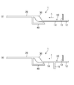
- FIG. 4 shows another example of the device 1.
- the upstream flow path section 10 of the present apparatus 1 cuts the liquid by supplying a liquid supply section 12 for supplying the liquid constituting the upstream liquid plugs PLu1, PLu2 (see FIG. 2A).
- the upstream flow path section 10 of the apparatus 1 is provided upstream of the liquid supply section 12, the gas supply section 13, the liquid supply section 12, and the gas supply section 13.
- a composition adjusting unit 15 for adjusting the composition of the upstream liquid plugs PLu1 and PLu2 by adding factors to the liquid plugs PLu1 and PLu2, and the upstream liquid plugs PLu1 and PLu2 whose compositions are adjusted are directed to the liquid holding unit 30.
- a merging flow path portion 14 for flowing Since the upstream flow path unit 10 further includes the composition adjustment unit 15, the plurality of upstream liquid plugs PLu1 and PLu2 whose compositions are adjusted in the upstream flow path unit 10 can be efficiently formed.
- the main liquid plug PLm held in the liquid holding unit 30 in (b) includes a cell body, and the first upstream liquid that flows to the upstream flow path unit 10 in (c) above.
- the upstream flow path section 10 is the first upstream liquid plug PLu1.
- / or the first upstream liquid plug PLu1 and the second upstream liquid plug having different concentrations of the stimulating substance by having the composition adjusting unit 15 for adding the stimulating substance to the second upstream liquid plug PLu2.
- PLu2 can be formed efficiently.
- FIG. 5 shows still another example of the device 1.
- the gas bypass channel 40 has an upstream end 41 that is not an enlarged channel.
- the cross-sectional area of the upstream end portion 41 of the gas bypass channel portion 40 is constant toward the downstream side of the gas bypass channel portion 40.
- the cross-sectional area of the opening at the downstream end portion 11 of the upstream flow passage portion 10 of the upstream end portion 41 of the gas bypass flow passage portion 40 is smaller than the cross-sectional area of the downstream end portion 11 of the upstream flow passage portion 10. Yes.
- the gas bypass flow path section 40 has an upstream end 41 including a short expanded flow path as compared with the above-described examples shown in FIGS. That is, the upstream end portion 41 opens to the downstream end portion 11 of the upstream flow passage portion 10 and extends substantially in a direction perpendicular to the flow direction from the downstream end portion 11. And a portion having a constant cross-sectional area extending downstream of the enlarged flow path portion in the direction.
- the present apparatus 1 has two gas bypass flow path portions 40. That is, in this example, the device 1 bypasses the liquid holding unit 30 from the downstream end 11 of the upstream flow path 10 to the upstream end 21 of the downstream flow path 20 on one side of the upstream flow path 10. On the other side of the first gas bypass flow path portion 40 and the upstream flow path portion 10 provided to do so, the upstream end portion 21 of the downstream flow path portion 20 extends from the downstream end portion 11 of the upstream flow path portion 10. And a second gas bypass channel 50 provided so as to bypass the liquid holding unit 30.
- the apparatus 1 as shown in FIG. 6 was manufactured by microfabrication technology. That is, as shown in FIG. 6I, the liquid supply unit 12 and the gas supply unit 13 are formed on the surface of a substrate 100 made of PDMS (polydimethylsiloxane) having a thickness of about 4 mm by replica molding using a photoresist.
- channel which comprises the upstream flow path part 10 containing, the downstream flow path part 20, the liquid holding
- the device 1 was obtained by laminating and bonding a PDMS (polydimethylsiloxane) substrate (not shown) having a thickness of about 2 mm to the PDMS substrate 100.
- FIG. 6 (ii) shows the dimensions of each part of the manufactured apparatus 1.
- the width of the merging channel portion 14 of the upstream channel portion 10 is 600 ⁇ m
- the width of the tip portion having a small cross-sectional area) is 120 ⁇ m
- the width of the downstream end portion 42 of the gas bypass channel portion 40 is 600 ⁇ m
- the upstream end portion 41 and the downstream end of the gas bypass channel portion 40 The width of the portion between the portions 42 was 500 ⁇ m
- the width of the downstream flow path portion 20 was 600 ⁇ m.
- the liquid holding unit 30 was a circle having a diameter of 2 mm. Moreover, all the heights of the upstream flow path part 10, the downstream flow path part 20, the liquid holding
- Examplementation of a method using a microchannel device The method was carried out using the apparatus 1 manufactured as described above.
- the liquid constituting the liquid plug water to which a dye for enhancing visibility was added was used. Air was used as the gas.
- the flow of the liquid and gas in the flow path was performed by applying pressure from upstream.
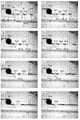
- FIG. 7 shows a result of observing the flow of the liquid plug in the apparatus 1 in the present method under a phase contrast microscope.
- the upstream flow path section 10 is filled with the gas bypass flow path section 40 filled with the gas Gb and the liquid holding section 30 holding the main liquid plug PLm.
- the three upstream liquid plugs PLu 1, PLu 2, PLu 3 were sequentially flowed toward the liquid holding part 30.
- the volume of the main liquid plug PLm was about 1.5 ⁇ L.
- the volume of each of the three upstream liquid plugs PLu1, PLu2, and PLu3 was about 100 nL.
- the first upstream liquid plug PLu1 is caused to flow into the liquid holding unit 30, thereby fusing the first upstream liquid plug PLu1 with the main liquid plug PLm. A part of the later main liquid plug PLm was pushed out to the downstream flow path portion 20.
- the gas Gu2 following the first upstream fluid plug PLu1 is caused to flow into the gas bypass channel 40, and a part of the gas Gb in the gas bypass channel 40 is downstream.
- a part of the main liquid plug PLm extruded to the downstream flow path portion 20 as described above was cut to form the first downstream liquid plug PLd1.
- the second upstream liquid plug PLu2 is caused to flow into the liquid holding unit 30 so as to fuse the second upstream liquid plug PLu2 with the main liquid plug PLm. A part of the later main liquid plug PLm was pushed out to the downstream flow path portion 20.
- the gas Gu3 following the second upstream fluid plug PLu2 is caused to flow into the gas bypass channel 40, and a part of the gas Gb in the gas bypass channel 40 is downstream.
- a part of the main liquid plug PLm extruded to the downstream flow path portion 20 as described above was cut to form a second downstream liquid plug PLd2.
- the third upstream liquid plug PLu3 is caused to flow into the liquid holding unit 30 so as to fuse the third upstream liquid plug PLu3 with the main liquid plug PLm, and after the fusion. A part of the main liquid plug PLm was pushed out to the downstream flow path portion 20.
- the gas Gu4 following the third upstream fluid plug PLu3 is caused to flow into the gas bypass channel 40, and a part of the gas Gb in the gas bypass channel 40 is downstream.
- a part of the main liquid plug PLm pushed to the downstream flow passage portion 20 as described above was cut to form a third downstream liquid plug PLd3.
- the three downstream liquid plugs PLd1, PLd2, and PLd3 were recovered from the downstream flow path portion 20.
Landscapes
- Chemical & Material Sciences (AREA)
- Health & Medical Sciences (AREA)
- Chemical Kinetics & Catalysis (AREA)
- Dispersion Chemistry (AREA)
- Clinical Laboratory Science (AREA)
- General Health & Medical Sciences (AREA)
- Analytical Chemistry (AREA)
- Life Sciences & Earth Sciences (AREA)
- Engineering & Computer Science (AREA)
- Bioinformatics & Cheminformatics (AREA)
- Organic Chemistry (AREA)
- Zoology (AREA)
- Wood Science & Technology (AREA)
- Hematology (AREA)
- Biochemistry (AREA)
- Sustainable Development (AREA)
- Microbiology (AREA)
- Biotechnology (AREA)
- General Engineering & Computer Science (AREA)
- Genetics & Genomics (AREA)
- Biomedical Technology (AREA)
- General Physics & Mathematics (AREA)
- Physics & Mathematics (AREA)
- Immunology (AREA)
- Pathology (AREA)
- Physical Or Chemical Processes And Apparatus (AREA)
- Apparatus Associated With Microorganisms And Enzymes (AREA)
- Measuring Or Testing Involving Enzymes Or Micro-Organisms (AREA)
- Micro-Organisms Or Cultivation Processes Thereof (AREA)
Abstract
微量液体の効果的な操作を実現するマイクロ流路装置及びこれに関する方法を提供する。本発明に係るマイクロ流路装置(1)は、上流液体プラグ及び気体を流すための上流流路部(10)と、下流液体プラグ及び気体を流すための下流流路部(20)と、前記上流流路部の下流端部と前記下流流路部の上流端部との間に設けられ主液体プラグを保持するための液体保持部(30)と、前記上流流路部の前記下流端部から前記下流流路部の前記上流端部まで前記液体保持部を迂回するように設けられ、前記液体保持部が前記主液体プラグを保持した状態で気体を流すための気体バイパス流路部(40)と、を備えている。
Description
本発明は、マイクロ流路装置及びこれに関する方法に関し、特に、マイクロ流路装置における微量液体の効果的な操作に関する。
従来、例えば、特許文献1には、内部に細胞が固着され且つ培養液が灌流される流路構造を有する細胞培養チャンバーが少なくとも2つ積層された細胞培養装置が記載されている。また、非特許文献1及び非特許文献2には、マイクロ流路装置の流路に液体プラグを流す技術が記載されている。
Fumihiro Sassa et al., Anal. Chem. 2008, 80,6206-6213
Fumihiro Sassa et al., Anal. Chem. 2010, 82,8725-8732
しかしながら、例えば、従来のマイクロ流路装置において、細胞培養チャンバーに保持される培養液の体積を一定に維持しつつ、細胞体(動物細胞、微生物等)に対する刺激物質を当該チャンバーに添加することにより、当該培養液中の細胞培養環境を経時的に変化させる(例えば、当該培養液中の当該刺激物質の濃度を段階的に増加させる)ことは困難であった。
また、例えば、従来のマイクロ流路装置において、細胞培養チャンバー内の微量な培養液中で培養されている細胞体に刺激物質を接触させる場合、当該刺激物質に対する当該細胞体の応答を評価するために、微量な当該培養液の一部を短い時間間隔で複数回効率よくサンプリングすることは困難であった。
本発明は、上記課題に鑑みて為されたものであり、微量液体の効果的な操作を実現するマイクロ流路装置及びこれに関する方法を提供することをその目的の一つとする。
上記課題を解決するための本発明の一実施形態に係る方法は、下記(a)~(g)を含むことを特徴とする:(a)上流流路部と、下流流路部と、前記上流流路部の下流端部と前記下流流路部の上流端部との間に設けられた液体保持部と、前記上流流路部の前記下流端部から前記下流流路部の前記上流端部まで前記液体保持部を迂回するように設けられた気体バイパス流路部と、を備えたマイクロ流路装置を用意すること;、(b)前記気体バイパス流路部に気体を満たすとともに、前記液体保持部に主液体プラグを保持すること;、(c)前記上流流路部に第一の上流液体プラグ及び第二の上流液体プラグを前記液体保持部に向けて順次流すこと;、(d)前記第一の上流液体プラグを前記液体保持部に流入させることにより、前記第一の上流液体プラグを前記主液体プラグと融合させるとともに、融合後の前記主液体プラグの一部を前記下流流路部に押し出すこと;、(e)前記第一の上流流体プラグに続く気体を前記気体バイパス流路部に流入させて前記気体バイパス流路部内の気体の一部を前記下流流路部の前記上流端部に押し出すことにより、前記主液体プラグの前記(d)で押し出された前記一部を切断して第一の下流液体プラグを形成すること;、(f)前記第二の上流液体プラグを前記液体保持部に流入させることにより前記第二の上流液体プラグを前記主液体プラグと融合させるとともに、融合後の前記主液体プラグの一部を前記下流流路部に押し出すこと;、(g)前記第二の上流液体プラグに続く気体を前記気体バイパス流路部に流入させて前記気体バイパス流路部内の気体の一部を前記下流流路部の前記上流端部に押し出すことにより、前記主液体プラグの前記(f)で押し出された前記一部を切断して第二の下流液体プラグを形成すること。本発明によれば、マイクロ流路装置において微量液体の効果的な操作を実現する方法を提供することができる。
また、前記方法は、下記(h)をさらに含むこととしてもよい:(h)前記第一の下流液体プラグ及び前記第二の下流液体プラグを回収すること。また、前記(e)において前記第一の下流液体プラグを形成してから1秒未満の時間内に、前記(g)において前記第二の下流液体プラグを形成するように、前記(c)において前記第一の上流液体プラグ及び前記第二の上流液体プラグを流すこととしてもよい。また、前記(d)において前記第一の上流液体プラグを前記主液体プラグと融合させてから1秒未満の時間内に、前記(f)において前記第二の上流液体プラグを前記主液体プラグと融合させるように、前記(c)において前記第一の上流液体プラグ及び前記第二の上流液体プラグを流すこととしてもよい。また、前記第一の上流液体プラグ、前記第二の上流液体プラグ、前記第一の下流液体プラグ及び前記第二の下流液体プラグのそれぞれの体積は、1μL未満であることとしてもよい。
また、前記(b)において前記液体保持部に保持される前記主液体プラグは、第一の因子を含み、前記(c)において前記上流流路部に流す前記第一の上流液体プラグ及び前記第二の上流液体プラグの一方又は両方は、前記第一の因子に作用する第二の因子を含むこととしてもよい。この場合、前記第一の因子は、細胞体であり、前記第二の因子は、前記細胞体に作用する物質であることとしてもよい。
上記課題を解決するための本発明の一実施形態に係るマイクロ流路装置は、上流液体プラグ及び気体を流すための上流流路部と、下流液体プラグ及び気体を流すための下流流路部と、前記上流流路部の下流端部と前記下流流路部の上流端部との間に設けられ主液体プラグを保持するための液体保持部と、前記上流流路部の前記下流端部から前記下流流路部の前記上流端部まで前記液体保持部を迂回するように設けられ、前記液体保持部が前記主液体プラグを保持した状態で気体を流すための気体バイパス流路部と、を備えたことを特徴とする。本発明によれば、微量液体の効果的な操作を実現するマイクロ流路装置を提供することができる。
また、前記マイクロ流路装置において、前記上流流路部、前記液体保持部及び前記気体バイパス流路部は、前記主液体プラグを保持する前記液体保持部に向けて前記上流流路部を流れる前記上流液体プラグが前記気体バイパス流路部に流入することなく前記液体保持部に流入し、前記主液体プラグを保持する前記液体保持部に向けて前記上流流路部を流れる前記気体が前記液体保持部に流入することなく前記気体バイパス流路部に流入するように設けられていることとしてもよい。
また、前記マイクロ流路装置において、前記上流流路部、前記液体保持部及び前記気体バイパス流路部は、前記気体バイパス流路部に前記気体が満たされ、前記液体保持部に前記主液体プラグが保持された状態において、前記上流液体プラグが前記上流流路部から前記液体保持部に流入する場合の自由エネルギー変化よりも、前記上流液体プラグが前記上流流路部から前記気体バイパス流路部に流入する場合の自由エネルギー変化が大きくなるように設けられていることとしてもよい。
本発明によれば、微量液体の効果的な操作を実現するマイクロ流路装置及びこれに関する方法を提供することができる。
以下に、本発明の一実施形態について説明する。なお、本発明は、本実施形態で示す例に限られるものではない。
図1には、本実施形態に係るマイクロ流路装置1(以下、「本装置1」という。)の一例を示す。図2A及び図2Bには、本実施形態に係る方法(以下、「本方法」という。)の一例に含まれる操作を示す。
本装置1は、図1、図2A及び図2Bに示すように、上流液体プラグPLu1,PLu2及び気体Gu1,Gu2,Gu3を流すための上流流路部10と、下流液体プラグPLd1,PLd2及び気体Gd1,Gd2,Gd3を流すための下流流路部20と、当該上流流路部10の下流端部11と当該下流流路部20の上流端部21との間に設けられ主液体プラグPLmを保持するための液体保持部30と、当該上流流路部10の当該下流端部11から当該下流流路部20の当該上流端部21まで当該液体保持部30を迂回するように設けられ、当該液体保持部30が当該主液体プラグPLmを保持した状態で気体Gbを流すための気体バイパス流路部40と、を備えている。
本方法は、図2A及び図2Bに示すように、下記(a)~(g)を含む:(a)上流流路部10と、下流流路部20と、当該上流流路部10の下流端部11と当該下流流路部20の上流端部21との間に設けられた液体保持部30と、当該上流流路部10の当該下流端部11から当該下流流路部20の当該上流端部21まで当該液体保持部30を迂回するように設けられた気体バイパス流路部40と、を備えたマイクロ流路装置1(本装置1)を用意すること;、(b)当該気体バイパス流路部40に気体Gbを満たすとともに、当該液体保持部30に主液体プラグPLmを保持すること;、(c)当該上流流路部10に第一の上流液体プラグPLu1及び第二の上流液体プラグPLu2を当該液体保持部30に向けて順次流すこと;、(d)当該第一の上流液体プラグPLu1を当該液体保持部30に流入させることにより、当該第一の上流液体プラグPLu1を当該主液体プラグPLmと融合させるとともに、融合後の当該主液体プラグPLmの一部を当該下流流路部20に押し出すこと;、(e)当該第一の上流流体プラグPLu1に続く気体Gu2を当該気体バイパス流路部40に流入させて当該気体バイパス流路部40内の気体Gbの一部を当該下流流路部20の当該上流端部21に押し出すことにより、当該主液体プラグPLmの当該(d)で押し出された当該一部を切断して第一の下流液体プラグPLd1を形成すること;、(f)当該第二の上流液体プラグPLu2を当該液体保持部30に流入させることにより、当該第二の上流液体プラグPLu2を当該主液体プラグPLmと融合させるとともに、融合後の当該主液体プラグPLmの一部を当該下流流路部20に押し出すこと;、(g)当該第二の上流液体プラグPLu2に続く気体Gu3を当該気体バイパス流路部40に流入させて当該気体バイパス流路部40内の気体Gbの一部を当該下流流路部20の当該上流端部21に押し出すことにより、当該主液体プラグPLmの当該(f)で押し出された当該一部を切断して第二の下流液体プラグPLd2を形成すること。
なお、図1、図2A及び図2Bにおいて、矢印Xの指す方向は、本装置1において液体及び気体が流れる方向を示す(他の図でも同様)。すなわち、矢印Xの指す方向は下流方向であり、当該矢印Xの指す方向と反対の方向は上流方向である。また、図2A及び図2Bに示す矢印Yは、気体バイパス流路部40における気体の流れを示す(他の図でも同様)。
本方法の上記(a)においては、本装置1を用意する。本装置1の上流流路部10は、液体保持部30に流入させる上流液体プラグPLu1,PLu2及び気体バイパス流路部40に流入させる気体Gu1,Gu2,Gu3が流れる流路である。
上流流路部10は、液体保持部30の上流に設けられ、その下流端部11で当該液体保持部30と接続されている。上流流路部10の下流端部11には、気体バイパス流路部40の上流端部41が開口している。
下流流路部20は、液体保持部30に保持された主液体プラグPLmから形成された下流液体プラグPLd1,PLd2及び気体バイパス流路部40から流出した気体Gd1,Gd2,Gd3が流れる流路である。
下流流路部20は、液体保持部30の下流に設けられ、その上流端部21で当該液体保持部30と接続されている。下流流路部20の上流端部21には、気体バイパス流路部40の下流端部42が開口している。
液体保持部30は、上流流路部10と下流流路部20との間に設けられている。すなわち、液体保持部30は、上流流路部10の下流端部11と、下流流路部20の上流端部21との間に設けられている。
より具体的に、液体保持部30は、上流流路部10の下流端部11に接続している気体バイパス流路部40の上流端部41(さらに具体的には、上流流路部10の下流端部11における気体バイパス流路部40の上流端部41の開口部)より下流であって、下流流路部20の上流端部21に接続している気体バイパス流路部40の下流端部42(さらに具体的には、下流流路部20の上流端部21における気体バイパス流路部40の下流端部42の開口部)より上流に設けられている。液体保持部30は、上流流路部10及び下流流路部20を含む主流路において当該上流流路部10と当該下流流路部20とを接続する中間流路であるともいえる。
液体保持部30の形状は、特に限られないが、図1、図2A及び図2Bに示すように、例えば、その少なくとも一部の断面積が、上流流路部10の下流端部11の断面積及び下流流路部20の上流端部21の断面積より大きいこととしてもよい。
気体バイパス流路部40は、液体保持部30が主液体プラグPLmを保持した状態で、上流流路部10を流れる気体を当該液体保持部30に流入させることなく下流流路部30に流入させるための流路である。
すなわち、気体バイパス流路部40は、液体保持部30が主液体プラグPLmを保持した状態で、上流流路部10を流れる気体を、当該液体保持部30を迂回させて、下流流路部20に導く流路である。したがって、上流流路部10及び下流流路部20とは異なり、気体バイパス流路部40に液体は流れない。
また、気体バイパス流路部40は、上記(c)から上記(g)までの間、その上流端41が上流流路部10の下流端部11に開口し、その下流端部42が下流流路部20の上流端部21に開口している以外は密閉されていることとしてもよい。すなわち、この場合、上記(c)から上記(g)までの間、気体バイパス流路部40においては、その上流端41から下流端部42への気体Gbの流れ以外に、当該気体Gbの流れはない。
なお、気体バイパス流路部40は、図1、図2A及び図2Bに示す例のように、その上流端部41及び下流端部42以外に開口部を有しないよう設けられることとしてもよいが、これに限られず、例えば、当該上流端部41及び下流端部42に加えて他の開口部を有するが、上記(c)から上記(g)までの間は当該他の開口部を閉じることとしてもよい。
また、図1、図2A及び図2Bに示す例において、気体バイパス流路部40は、拡大流路である上流端部41を有している。すなわち、気体バイパス流路部40の上流端部41の断面積は、当該気体バイパス流路部40の下流に向けて増加している。また、この気体バイパス流路部40の上流端部41の上流流路部10の下流端部11における開口の断面積は、当該上流流路部10の下流端部11の断面積より小さくなっている。
また、図1、図2A及び図2Bに示す例において、気体バイパス流路部40の上流端部41は、上流流路部10の下流端部11から、当該上流流路部10内における流れ方向に対して略直行する方向に延びている。
本装置1を製造する方法は、上述のような上流流路部10、下流流路部20、液体保持部30及び気体バイパス流路部40を備えるマイクロ流路装置を製造する方法であれば特に限られないが、本装置1は、例えば、基板と、当該基板の表面に溝として形成された当該上流流路部10、下流流路部20、液体保持部30及び気体バイパス流路部40とを備えることとしてもよい。
この場合、基板を構成する材料は、特に限られないが、例えば、樹脂(例えば、PDMS)製又はガラス製であることとしてもよい。そして、上流流路部10、下流流路部20、液体保持部30及び気体バイパス流路部40は、例えば、フォトリソグラフィ等のマイクロファブリケーション技術により、基板の表面に形成されることとしてもよい。
本装置1は、特に、微量の液体及び気体を操作するために好ましく使用される。すなわち、液体保持部30の体積(すなわち、液体保持部30に保持される主液体プラグPLmの体積)は、例えば、0.1μL~1000μLであることとしてもよく、0.1μL~500μLであることとしてもよく、0.1μL~100μLであることとしてもよい。また、上流流路部10、下流流路部20及び気体バイパス流路部40の断面積は、例えば、0.01mm2~1.0mm2であることとしてもよく、0.01mm2~0.1mm2であることとしてもよい。
本装置1において、上流流路部10、液体保持部30及び気体バイパス流路部40は、主液体プラグPLmを保持する当該液体保持部30に向けて当該上流流路部10を流れる上流液体プラグPLu1,PLu2が当該気体バイパス流路部40に流入することなく当該液体保持部30に流入し、当該主液体プラグPLmを保持する当該液体保持部30に向けて当該上流流路部10を流れる気体Gu1,Gu2,Gu3が当該液体保持部30に流入することなく当該気体バイパス流路部40に流入するように設けられていることとしてもよい。
すなわち、本装置1においては、例えば、主液体プラグPLmを保持する液体保持部30に向けて上流流路部10を流れる上流液体プラグPLu1,PLu2は、気体バイパス流路部40の下流端部42が開放された状態で、当該気体バイパス流路部40に流入することなく当該液体保持部30に流入し、当該主液体プラグPLmを保持する当該液体保持部30に向けて当該上流流路部10を流れる気体Gu1,Gu2,Gu3は、当該液体保持部30の下流端部32が開放された状態で、当該液体保持部30に流入することなく当該気体バイパス流路部40に流入する。
このような上流液体プラグPLu1,PLu2,PLu3の液体保持部30への選択的な流入、及び気体Gu1,Gu2,Gu3の気体バイパス流路部40への選択的な流入を実現する方法は特に限られないが、例えば、上流流路部10、液体保持部30及び気体バイパス流路部40は、当該気体バイパス流路部40に気体Gbが満たされ、当該液体保持部30に主液体プラグPLmが保持された状態において、上流液体プラグPLu1,PLu2が当該上流流路部10から当該液体保持部30に流入する場合の自由エネルギー変化よりも、当該上流液体プラグPLu1,PLu2が当該上流流路部10から当該気体バイパス流路部40に流入する場合の自由エネルギー変化が大きくなるように設けられていることとしてもよい。
具体的に、例えば、図1、図2A及び図2Bに示すように、気体バイパス流路部40の上流端部41が拡大流路である場合(すなわち、当該上流端部41の断面積が下流に向けて増加する場合)、気体(具体的には、上流流路部10を流れる気体Gu1,Gu2,Gu3及び気体バイパス流路部40内の気体Gb)中における、当該上流端部41の内表面41aの上流液体プラグPLu1,PLu2を構成する液体に対する接触角が90°以上であり、且つ、当該上流液体プラグPLu1,PLu2が上流流路部10の下流端部11から液体保持部30に流入する場合の気液界面の面積の増加率よりも、当該上流液体プラグPLu1,PLu2が当該上流流路部10の当該下流端部11から当該気体バイパス流路部40に流入する場合の気液界面の面積の増加率の方が大きくなるように設けられていることとしてもよい。
ここで、上流液体プラグPLu1,PLu2が上流流路部10の下流端部11から液体保持部30に流入する場合の気液界面の面積の増加率は、上流液体プラグPLu1,PLu2が当該下流端部11に保持されている状態での気液界面の面積に対する、当該上流液体プラグPLu1,PLu2が当該保持部30の上流端部31に保持されている状態での気液界面の面積の比率である。
また、上流液体プラグPLu1,PLu2が上流流路部10の下流端部11から気体バイパス流路部40に流入する場合の気液界面の面積の増加率は、上流液体プラグPLu1,PLu2が当該下流端部11に保持されている状態での気液界面の面積に対する、当該上流液体プラグPLu1,PLu2が当該気体バイパス流路部40の上流端部41に保持されている状態での気液界面の面積の比率である。
また、気体バイパス流路部40の上流端部41が拡大流路でない場合(例えば、当該上流端部41の断面積が下流に向けて一定である場合)、気体(具体的には、上流流路部10を流れる気体Gu1,Gu2,Gu3及び気体バイパス流路部40内の気体Gb)中における、当該上流端部41の内表面41aの上流液体プラグPLu1,PLu2を構成する液体に対する接触角が90°以上であり、且つ、当該上流液体プラグPLu1,PLu2が上流流路部10の下流端部11から液体保持部30に流入する場合の濡れ辺長が、当該上流液体プラグPLu1,PLu2が当該上流流路部10の当該下流端部11から気体バイパス流路部40に流入する場合の濡れ辺長より大きくなるように設けられていることとしてもよい。
ここで、上流液体プラグPLu1,PLu2が上流流路部10の下流端部11から液体保持部30に流入する場合の濡れ辺長は、例えば、当該液体保持部30の上流端部31の最も上流側の部分の断面形状が幅W1(μm)及び高さH1(μm)の長方形である場合、2×W1×H1(μm2)である。
また、上流液体プラグPLu1,PLu2が上流流路部10の下流端部11から気体バイパス流路部40に流入する場合の濡れ辺長は、例えば、当該気体バイパス流路部40の上流端部41の最も上流側の部分の断面形状が幅W2(μm)及び高さH2(μm)の長方形である場合、2×W2×H2(μm2)である。
また、上述した気体バイパス流路部40の上流端部41の内表面41aの上流液体プラグPLu1,PLu2を構成する液体に対する接触角は、90°以上、180°未満であれば特に限られないが、例えば、100°以上であることとしてもよい。
なお、気体バイパス流路部40の上流端部41の内表面41aの液体に対する接触角を調節する方法は、特に限られないが、例えば、上流液体プラグPLu1,PLu2を構成する液体、上流流路部10を流れる気体Gu1,Gu2,Gu3及び気体バイパス流路部40内の気体Gb、当該内表面41aを構成する材料の組み合わせによって調節することとしてもよい。
具体的に、例えば、気体バイパス流路部40が基板の表面に溝を形成することにより設けられる場合には、当該基板を構成する材料の選択、及び/又は当該気体バイパス流路部40の上流端部41の内表面41aに対する疎水化処理によって、当該内表面41aの液体に対する接触角を上述した範囲に調節することとしてもよい。
本方法の上記(b)においては、気体バイパス流路部40に気体Gbを満たすとともに、液体保持部30に主液体プラグPLmを保持する。具体的には、図2A(i)に示すように、上流流路部10の下流端部11、気体バイパス流路部40及び下流流路部20の上流端部21に気体を保持するとともに、当該上流流路部10の下流端部11と当該下流流路部20の上流端部21との間の液体保持部30に液体を保持する。すなわち、主液体プラグPLmは、上流流路部10の下流端部11に保持された気体と、下流流路部20の上流端部21に保持された気体とに挟まれた液体プラグである。
ここで、気体バイパス流路部40に気体Gbを満たすとともに、液体保持部30に主液体プラグPLmを保持する方法は、特に限られないが、例えば、図3A及び図3Bに示すような操作を含む方法を使用することとしてもよい。
すなわち、図3A及び図3Bに示すように、上記(b)においては、下記(b1)~(b5)を順次行うことにより、気体バイパス流路部40に気体Gbを満たすとともに、液体保持部30に主液体プラグPLmを保持することとしてもよい:(b1)上流流路部10、下流流路部20、液体保持部30及び気体バイパス流路部40に気体を満たすこと(図3A(i));、(b2)上流流路部10に液体保持部30に向けて、当該液体保持部30の体積より大きな体積の液体プラグPL0を流すこと(図3A(ii));、(b3)当該液体プラグPL0を気体バイパス流路部40に流入させることなく当該液体保持部30に流入させて、上流流路部10の下流端部11、当該液体保持部30及び下流流路部20の上流端部21に保持すること(図3A(iii));、(b4)当該液体プラグPL0に続く気体G1を当該液体保持部30に流入させることなく当該上流流路部10の下流端部11から当該気体バイパス流路部40に流入させて、当該気体バイパス流路部40内の気体Gbの一部を当該下流流路部20の当該上流端部21に押し出すことにより、当該液体プラグPL0当該下流流路部20の上流端部21に保持されている部分を切断して下流液体プラグPLd0を形成すること(図3A(iv)、図3B(v));、(b5)当該下流流路部20内の当該下流液体プラグPLd0をさらに下流に流すこと(図3B(vi)、図3B(vii))。
本方法の上記(c)においては、上流流路部10に第一の上流液体プラグPLu1及び第二の上流液体プラグPLu2を液体保持部30に向けて順次流す。すなわち、図2A(ii)に示すように、その下流側の気体Gu1及び上流側の気体Gu2に挟まれた第一の上流液体プラグPLu1と、当該第一の上流液体プラグPLu1の下流において、その下流側の気体Gu2及び上流側の気体Gu3に挟まれた第二の上流液体プラグPLu2とを順次流す。
第一の上流液体プラグPLu1及び第二の上流液体プラグPLu2の体積は、上記(d)及び上記(f)で下流流路部20に押し出された主液体プラグPLmの一部が、当該下流流路部20の上流端部21を満たす(すなわち、当該一部が、当該上流端部21における気体バイパス流路部40の下流端部42の開口を塞ぐ)範囲であれば、特に限られないが、例えば、液体保持部30に保持される当該主液体プラグPLmの体積以下であることとしてもよく、当該主液体プラグPLmの体積より小さいこととしてもよい。
また、第一の上流液体プラグPLu1及び第二の上流液体プラグPLu2の体積は、例えば、1μL未満であることとしてもよく、500nL以下であることとしてもよく、200nL以下であることとしてもよい。また、第一の上流液体プラグPLu1及び第二の上流液体プラグPLu2の体積は、例えば、1nL以上であることとしてもよい。
また、上記(c)においては、上記(e)において第一の下流液体プラグPLd1を形成してから1秒未満の時間内に、上記(g)において第二の下流液体プラグPLd2を形成するように、第一の上流液体プラグPLu1及び第二の上流液体プラグPLu2を流すこととしてもよい。
この場合、1秒未満の時間間隔での複数回のサンプリングが実現される。上記時間間隔は、例えば、500ミリ秒以下であることとしてもよい。また、上記時間間隔は、例えば、1ミリ秒以上であることとしてもよい。
この複数の下流液体プラグPLd1,PLd2を形成する時間間隔は、例えば、第一の上流液体プラグPLu1と第二の上流液体プラグPLu2との間の気体Gu2の体積、当該第二の上流液体プラグPLu2の体積及び当該第二の上流液体プラグPLu2の流速からなる群より選択される1つ以上により上述の範囲に調節することとしてもよい。
また、上記(c)においては、上記(d)において第一の上流液体プラグPLu1を主液体プラグPLmと融合させてから1秒未満の時間内に、上記(f)において第二の上流液体プラグPLu2を当該主液体プラグPLmと融合させるように、当該第一の上流液体プラグPLu1及び当該第二の上流液体プラグPLu2を流すこととしてもよい。
この場合、1秒未満の時間間隔での複数の上流液体プラグPLu1,PLu2と主液体プラグPLmとの融合が実現される。上記時間間隔は、例えば、500ミリ秒以下であることとしてもよい。また、上記時間間隔は、例えば、1ミリ秒以上であることとしてもよい。
この複数の上流液体プラグPLu1,PLu2と主液体プラグPLmとを融合させる時間間隔は、例えば、第一の上流液体プラグPLu1の体積、当該第一の上流液体プラグPLu1と第二の上流液体プラグPLu2との間の気体Gu2の体積、及び当該上流液体プラグPLu1,PLu2の流速からなる群より選択される1つ以上により上述の範囲に調節することとしてもよい。
上流流路部10において第一の上流液体プラグPLu1及び第二の上流液体プラグPLu2を流す方法は、特に限られないが、例えば、当該第一の上流液体プラグPLu1及び第二の上流液体プラグPLu2に対して上流から圧力をかけることにより流すこととしてもよいし、下流から減圧することにより流すこととしてもよい。
上記(c)において上流流路部10に流す液体プラグの数は、2つ以上であれば特に限られず、3つ以上の液体プラグを流すこととしてもよい。すなわち、上記(c)においては、気体を介して互いに離れて配置された複数の上流液体プラグを流すこととすればよい。
本方法の上記(d)においては、第一の上流液体プラグPLu1を液体保持部30に流入させることにより、当該第一の上流液体プラグPLu1を主液体プラグPLmと融合させるとともに、融合後の当該主液体プラグPLmの一部を下流流路部20に押し出す。
すなわち、まず、図2A(iii)に示すように、第一の上流液体プラグPLu1を気体バイパス流路部40に流入させることなく液体保持部30に流入させることにより、当該第一の上流液体プラグPLu1を主液体プラグPLmと融合させる。
次に、図2A(iv)に示すように、第一の上流液体プラグPLu1に続く気体Gu2を上流流路部10の下流端部11まで流すことにより、主液体プラグPLmの一部を、下流流路部20の上流端部21より下流まで押し出す。
なお、このとき、液体保持部30から押し出される主液体プラグPLmの一部の体積は、第一の上流液体プラグPLu1の体積と同一である。また、融合後の主液体プラグPLmの体積は、融合前の主液体プラグPLmの体積と第一の上流液体プラグPLu1の体積との合計である。
第一の上流液体プラグPLu1と主液体プラグPLmとの融合により、当該第一の上流液体プラグPLu1を構成する液体と、当該主液体プラグPLmを構成する液体とが混合される。
本方法の上記(e)においては、第一の上流流体プラグPLu1に続く気体Gu2を気体バイパス流路部40に流入させて当該気体バイパス流路部40内の気体Gbの一部を下流流路部20の上流端部21に押し出すことにより、主液体プラグPLmの上記(d)で押し出された一部を切断して第一の下流液体プラグPLd1を形成する。
すなわち、図2A(v)に示すように、第一の上流流体プラグPLu1に続く気体Gu2を液体保持部30に流入させることなく気体バイパス流路部40に流入させることにより、当該気体バイパス流路部40に保持されていた気体Gbの一部を下流流路部20の上流端部21に押し出す。
その結果、上記(d)において下流流路部20に押し出されていた主液体プラグPLmの一部(図2A(iv)参照)は、液体保持部30に保持された残りの部分から切り離されて、第一の下流液体プラグPLd1となる。
この第一の下流液体プラグPLd1の体積は、第一の上流液体プラグPLu1の体積と同一である。すなわち、例えば、上述のように、第一の上流液体プラグPLu1の体積が1μL未満である場合、第一の下流液体プラグPLd1の体積もまた、1μL未満であり、当該第一の上流液体プラグPLu1の体積と同一である。
本方法の上記(f)においては、第二の上流液体プラグPLu2を液体保持部30に流入させることにより、当該第二の上流液体プラグPLu2を主液体プラグPLmと融合させるとともに、融合後の当該主液体プラグPLmの一部を下流流路部20に押し出す。
すなわち、上述した第一の上流液体プラグPLu1の場合と同様、まず、図2B(vi)に示すように、第二の上流液体プラグPLu2を気体バイパス流路部40に流入させることなく液体保持部30に流入させることにより、当該第二の上流液体プラグPLu2を主液体プラグPLmと融合させる。
次に、図2B(vii)に示すように、第二の上流液体プラグPLu2に続く気体Gu3を上流流路部10の下流端部11まで流すことにより、主液体プラグPLmの一部を、下流流路部20の上流端部21より下流まで押し出す。
なお、このとき、液体保持部30から押し出される主液体プラグPLmの一部の体積は、第二の上流液体プラグPLu2の体積と同一である。また、融合後の主液体プラグPLmの体積は、融合前の主液体プラグPLmの体積と第二の上流液体プラグPLu2の体積との合計である。
第二の上流液体プラグPLu2と主液体プラグPLmとの融合により、当該第二の上流液体プラグPLu2を構成する液体と、当該主液体プラグPLmを構成する液体とが混合される。
すなわち、第二の上流液体プラグPLu2と主液体プラグPLmとの融合により、第一の上流液体プラグPLu1と融合する前の主液体プラグPLmを構成する液体と、当該第一の上流液体プラグPLu1を構成する液体と、当該第二の上流液体プラグPLu2を構成する液体とが混合される。
また、上述のとおり、第二の上流液体プラグPLu2と主液体プラグPLmとの融合は、上記(d)において第一の上流液体プラグPLu1が主液体プラグPLmと融合してから1秒未満の時間内に行われることとしてもよい。
本方法の上記(g)においては、第二の上流液体プラグPLu2に続く気体Gu3を気体バイパス流路部40に流入させて当該気体バイパス流路部40内の気体Gbの一部を下流流路部20の上流端部21に押し出すことにより、主液体プラグPLmの上記(f)で押し出された一部を切断して第二の下流液体プラグPLd2を形成する。
すなわち、上述した第一の下流液体プラグPLd1の場合と同様、図2B(viii)に示すように、第二の上流流体プラグPLu2に続く気体Gu3を液体保持部30に流入させることなく気体バイパス流路部40に流入させることにより、当該気体バイパス流路部40に保持されていた気体Gbの一部を下流流路部20の上流端部21に押し出す。
その結果、上記(f)において下流流路部20に押し出されていた主液体プラグPLmの一部(図2B(vii)参照)は、液体保持部30に保持された残りの部分から切り離されて、第二の下流液体プラグPLd2となる。
この第二の下流液体プラグPLd2の体積は、第二の上流液体プラグPLu2の体積と同一である。すなわち、例えば、上述のように、第二の上流液体プラグPLu2の体積が1μL未満である場合、第二の下流液体プラグPLd2の体積もまた、1μL未満であり、当該第二の上流液体プラグPLu2の体積と同一である。
また、上述のとおり、第二の下流液体プラグPLd2は、上記(e)において第一の下流液体プラグPLd1が形成されてから1秒未満の時間内に形成されることとしてもよい。この場合、上述のとおり、1秒未満の時間間隔での複数個の下流液体プラグPLd1,PLd2の形成が実現される。
上述した本装置1及び本方法によれば、マイクロ流路装置における微量液体の効果的な操作が実現される。すなわち、特に、気体バイパス流路部40を備えた本装置1を使用して、複数の上流液体プラグPLu1,PLu2を間欠的に順次、主液体プラグPLmと融合させるとともに、当該複数の上流液体プラグPLu1,PLu2の各々に続く気体Gu2,Gu3を液体保持部30に流入させることなく上流流路部10から下流流路部20に迂回させることにより、当該複数の上流液体プラグPLu1,PLu2に対応する複数の下流液体プラグPLd1,PLd2を間欠的に順次形成して、当該主液体プラグPLmの体積を一定に維持することができる。
また、例えば、上述のとおり、上流流路部10において複数の上流液体プラグPLu1,PLu2を流す条件を調節することにより、上記(d)において第一の上流液体プラグPLu1を主液体プラグPLmと融合させてから1秒未満の時間内に、上記(f)において第二の上流液体プラグPLu2を当該主液体プラグPLmと融合させることもできる。
この場合、極めて高い時間分解能で複数回の上流液体プラグPLu1,PLu2と主液体プラグPLmとの融合(すなわち、当該上流液体プラグPLu1,PLu2を構成する液体と当該主液体プラグPLmを構成する液体との混合)を行うことができる。
また、上述した本装置1及び本方法によれば、マイクロ流路装置における効果的なサンプリングが実現される。すなわち、特に、気体バイパス流路部40を備えた本装置1を使用して、複数の上流液体プラグPLu1,PLu2の各々に続く気体Gu2,Gu3を液体保持部30に流入させることなく上流流路部10から下流流路部20に迂回させることにより、複数回の間欠的なサンプリングとして、所望の時間間隔で複数の下流液体プラグPLd1,PLd2を形成することができる。
具体的に、例えば、上述のとおり、第二の下流液体プラグPLd2は、上記(e)において第一の下流液体プラグPLd1が形成されてから1秒未満の時間内に形成されることとしてもよい。すなわち、上流流路部10において複数の上流液体プラグPLu1,PLu2を流す条件を調節することにより、上記(e)において第一の下流液体プラグPLd1を形成してから1秒未満の時間内に、上記(g)において第二の下流液体プラグPLd2を形成することができる。この場合、1秒未満の時間間隔での複数回のサンプリングが実現される。すなわち、極めて高い時間分解能で複数回のサンプリングを行うことができる。
また、例えば、上述のとおり、第一の上流液体プラグPLu1、第二の上流液体プラグPLu2、第一の下流液体プラグPLd1及び第二の下流液体プラグPLd2のそれぞれの体積が、1μL未満である場合には、極微量の液体の効果的な操作を実現することができる。
また、本方法は、下記(h)をさらに含むこととしてもよい:(h)当該第一の下流液体プラグPLd1及び当該第二の下流液体プラグPLd2を回収すること。この場合、本方法の上記(h)においては、第一の下流液体プラグPLd1及び第二の下流液体プラグPLd2を回収する。すなわち、図2B(ix)、(x)に示すように、上述のようにして形成された第一の下流液体プラグPLd1及び第二の下流液体プラグPLd2を下流流路部20から回収する。また、上記(h)においては、回収された第一の下流液体プラグPLd1及び第二の下流液体プラグPLd2を分析することとしてもよい。
また、本方法においては、上記(b)において液体保持部30に保持される主液体プラグPLmは、第一の因子を含み、上記(d)において前記上流流路部に流す第一の上流液体プラグPLu1及び第二の上流液体プラグPLu2の一方又は両方は、当該第一の因子に作用する第二の因子を含むこととしてもよい。
この場合、上記(d)及び/又は上記(f)において、上流液体プラグPLu1,PLu2を主液体プラグPLmと融合させることにより、第一の因子に第二の因子を作用させることができる。なお、第一の因子は、液体保持部30に固定されていることとしてもよい。
また、第二の因子は、主液体プラグPLm中において、第一の因子に直接的に作用することとしてもよいし、第一の因子に対して間接的に作用することとしてもよい。第一の因子に対する第二の因子の間接的な作用は、例えば、主液体プラグPLm中において、まず当該第二の因子から第三の因子が生成され、次いで、当該第三の因子が第一の因子に作用することにより行われることとしてもよい。
具体的に、例えば、第一の因子は、細胞体であり、第二の因子は、当該細胞体に作用する物質(例えば、刺激物質)であることとしてもよい。この場合、細胞体は、液体保持部30に固定されていることとしてもよい。
細胞体は、特に限られないが、例えば、動物細胞であることとしてもよい。動物細胞は、例えば、哺乳類の細胞であることとしてもよい。すなわち、動物細胞は、例えば、ヒト又はヒト以外の動物(例えば、サル、ブタ、イヌ、ラット又はマウス)の細胞であることとしてもよい。また、動物細胞は、ヒト又はヒト以外の動物から採取された初代細胞であることとしてもよく、樹立された株化細胞であることとしてもよい。また、動物細胞は、分化した細胞であることとしてもよく、未分化の細胞であることとしてもよい。また、動物細胞は、胚性幹(Embryonic Stem)細胞又はこれに由来する細胞であることとしてもよく、iPS(induced Pluripotent Stem)細胞又はこれに由来する細胞であることとしてもよい。また、細胞体は、哺乳類以外の動物細胞であることとしてもよい。また、細胞体は、例えば、微生物であることとしてもよい。また、細胞体は、例えば、植物細胞であることとしてもよい。
本装置1及び本方法は、上述のとおり、極めて微量の液体を操作することができるため、例えば、各々が希少な刺激物質を含む極微量の液体からなる複数の上流液体プラグPLu1,PLu2を間欠的に順次、少量の希少な細胞体を含む微量の主液体プラグPLmに融合させるとともに、当該複数の上流液体プラグPLu1,PLu2に対応する複数の下流液体プラグPLd1,PLd2を間欠的に順次形成することにより、当該主液体プラグPLmの体積を一定に維持しつつ、当該主液体プラグPLmに含まれる当該刺激物質の濃度を段階的に増加させて、当該細胞体の培養環境の変化を高精度に制御することができる。
また、本装置1及び本方法は、上述のとおり、複数の上流液体プラグPLu1,PLu2に対応する複数の下流液体プラグPLd1,PLd2を間欠的に順次形成することによる効果的な複数回のサンプリングを実現するため、例えば、主液体プラグPLmに含まれる少量の希少な細胞体の刺激物質に対する応答を効果的に評価することができる。
具体的に、例えば、上記(b)において液体保持部30に保持される主液体プラグPLmは、細胞体を含み、上記(c)において上流流路部10に流す第一の上流液体プラグPLu1及び第二の上流液体プラグPLu2の一方又は両方は、当該細胞体の分泌量(細胞体が分泌する特定物質の量)及び/又は分泌速度(細胞体が特定物質を分泌する速度)を変化させる刺激物質を含むこととしてもよい。
より具体的に、例えば、上記(b)において液体保持部30に保持される主液体プラグPLmに含まれる細胞体はランゲルハンス細胞であり、上記(c)において上流流路部10に流す第一の上流液体プラグPLu1及び第二の上流液体プラグPLu2の一方又は両方はグルコースを含むこととしてもよい。
この場合、ランゲルハンス細胞により分泌される特定物質はインスリンであり、グルコースはランゲルハンス細胞のインスリンの分泌量及び/又は分泌速度を変化させる刺激物質である。
そして、上記(b)において液体保持部30に保持される主液体プラグPLmが細胞体を含み、上記(c)において上流流路部10に流す第一の上流液体プラグPLu1及び第二の上流液体プラグPLu2の一方又は両方が当該細胞体の分泌量及び/又は分泌速度を変化させる刺激物質を含む場合、上記(d)及び/又は上記(f)において、上流液体プラグPLu1,PLu2を主液体プラグPLmと融合させることにより、当該液体保持部30において当該刺激物質を当該細胞体に作用させ、上記(e)及び/又は上記(g)において、当該刺激物質の作用により変化した量及び/又は速度で当該細胞体から分泌された特定物質を含む第一の下流液体プラグPLd1及び/又は第二の下流液体プラグPLd2を形成することができる。
したがって、上記(h)において第一の下流液体プラグPLd1及び/又は第二の下流液体プラグPLd2を回収し、分析することにより、刺激物質に対する細胞体の応答を、上述したような高い時間分解能で評価することができる。
なお、刺激物質に対する細胞体の応答は、サンプリングを行うことなく評価することとしてもよい。すなわち、例えば、顕微鏡の試料ステージに配置された本装置1において、細胞体を含む主液体プラグPLmに刺激物質を含む複数の上流液体プラグPLu1,PLu2を融合させるとともに、複数の下流液体プラグPLd1,PLd2を形成することにより、当該刺激物質に対する当該細胞体の応答を当該顕微鏡下で観察し、評価することができる。
また、第一の因子は、細胞体に限られない。すなわち、例えば、第一の因子は、第一の物質であり、第二の因子は、当該第一の物質との相互作用により第三の物質を生成する第二の物質であることとしてもよい。
具体的に、例えば、第一の因子は、液体保持部30に固定された酵素であり、第二の因子は、当該酵素の基質であることとしてもよい。この場合、上記(d)及び/又は上記(f)において、基質を含む上流液体プラグPLu1,PLu2を、酵素を含む主液体プラグPLmと融合させることにより、当該液体保持部30において当該基質を当該酵素と接触させて酵素反応を行い、上記(e)及び/又は上記(g)において、当該酵素反応による生成物質を含む第一の下流液体プラグPLd1及び/又は第二の下流液体プラグPLd2を形成することができる。
したがって、上記(h)において第一の下流液体プラグPLd1及び/又は第二の下流液体プラグPLd2を回収し、分析することにより、酵素反応による生成物質の量や、酵素反応速度を、上述したような高い時間分解能で評価することができる。
図4には、本装置1の他の例を示す。図4(i)に示す例において、本装置1の上流流路部10は、上流液体プラグPLu1,PLu2(図2A参照)を構成する液体を供給する液体供給部12と、当該液体を切断して当該上流液体プラグPLu1,PLu2を形成するための気体を供給する気体供給部13と、形成された当該上流液体プラグPLu1,PLu2を液体保持部30に向けて流すための合流流路部14とを有している。上流流路部10が液体供給部12及び気体供給部13を有することにより、上流流路部10において複数の上流液体プラグPLu1,PLu2を効率よく形成することができる。
図4(ii)に示す例において、本装置1の上流流路部10は、液体供給部12と、気体供給部13と、当該液体供給部12及び当該気体供給部13の下流に設けられ上流液体プラグPLu1,PLu2に因子を添加して当該上流液体プラグPLu1,PLu2の組成を調節するための組成調節部15と、組成が調節された当該上流液体プラグPLu1,PLu2を液体保持部30に向けて流すための合流流路部14と、を有している。上流流路部10が、さらに組成調節部15を有することにより、当該上流流路部10において組成が調節された複数の上流液体プラグPLu1,PLu2を効率よく形成することができる。
具体的に、例えば、上述したように上記(b)において液体保持部30に保持される主液体プラグPLmが細胞体を含み、上記(c)において上流流路部10に流す第一の上流液体プラグPLu1及び第二の上流液体プラグPLu2の一方又は両方が当該細胞体の分泌量及び/又は分泌速度を変化させる刺激物質を含む場合、当該上流流路部10が当該第一の上流液体プラグPLu1及び/又は当該第二の上流液体プラグPLu2に当該刺激物質を添加する組成調節部15を有することにより、当該刺激物質の濃度が互いに異なる当該第一の上流液体プラグPLu1及び第二の上流液体プラグPLu2を効率よく形成することができる。
図5には、本装置1のさらに他の例を示す。図5(i)に示す例において、気体バイパス流路部40は、拡大流路ではない上流端部41を有している。すなわち、この例において、気体バイパス流路部40の上流端部41の断面積は、当該気体バイパス流路部40の下流に向けて一定となっている。また、この気体バイパス流路部40の上流端部41の上流流路部10の下流端部11における開口の断面積は、当該上流流路部10の下流端部11の断面積より小さくなっている。
図5(ii)に示す例において、気体バイパス流路部40は、上述した図1~図4に示す例に比べて短い拡大流路を含む上流端部41を有している。すなわち、この上流端部41は、上流流路部10の下流端部11に開口して当該下流端部11から流れ方向に対して略直行する方向に延びる拡大流路部分と、当該略直行する方向において当該拡大流路部分の下流に延びる断面積が一定の部分とを含んでいる。
図5(iii)に示す例において、本装置1は、2つの気体バイパス流路部40を有している。すなわち、この例において、本装置1は、上流流路部10の一方側において、当該上流流路部10の下流端部11から下流流路部20の上流端部21まで液体保持部30を迂回するように設けられた第一の気体バイパス流路部40と、当該上流流路部10の他方側において、当該上流流路部10の下流端部11から下流流路部20の上流端部21まで液体保持部30を迂回するように設けられた第二の気体バイパス流路部50とを備えている。
次に、本実施形態に係る具体的な実施例について説明する。
[マイクロ流路装置の製造]
マイクロファブリケーション技術により、図6に示すような本装置1を製造した。すなわち、図6(i)に示すように、フォトレジストを使用したレプリカ成形により、厚さ約4mmのPDMS(ポリジメチルシロキサン)製の基板100の表面に、液体供給部12及び気体供給部13を含む上流流路部10と、下流流路部20と、液体保持部30と、拡大流路である上流端部41を有する気体バイパス流路部40とを構成する溝を形成した。そして、このPDMS製の基板100に、厚さ約2mmのPDMS(ポリジメチルシロキサン)製の基板(不図示)を積層して接着することにより、本装置1を得た。
マイクロファブリケーション技術により、図6に示すような本装置1を製造した。すなわち、図6(i)に示すように、フォトレジストを使用したレプリカ成形により、厚さ約4mmのPDMS(ポリジメチルシロキサン)製の基板100の表面に、液体供給部12及び気体供給部13を含む上流流路部10と、下流流路部20と、液体保持部30と、拡大流路である上流端部41を有する気体バイパス流路部40とを構成する溝を形成した。そして、このPDMS製の基板100に、厚さ約2mmのPDMS(ポリジメチルシロキサン)製の基板(不図示)を積層して接着することにより、本装置1を得た。
図6(ii)には、製造された本装置1の各部の寸法を示す。すなわち、上流流路部10の合流流路部14の幅は600μmであり、上流流路部10の下流端部11における気体バイパス流路部40の上流端部41の開口(拡大流路の最も断面積が小さい先端部)の幅は120μmであり、当該気体バイパス流路部40の下流端部42の幅は600μmであり、当該気体バイパス流路部40の当該上流端部41と当該下流端部42との間の部分の幅は500μmであり、下流流路部20の幅は600μmであった。
また、液体保持部30は、直径が2mmの円形であった。また、上流流路部10、下流流路部20、液体保持部30及び気体バイパス流路部40の全ての高さは150μmであった。また、上流流路部10、下流流路部20、液体保持部30及び気体バイパス流路部40の内表面にはフッ素系樹脂のコーティングによる疎水化処理を施した。その結果、空気中における、気体バイパス流路部40の上流端部41の内表面41aを含む、各流路の内表面の水に対する接触角は、120°であった。
[マイクロ流路装置を使用する方法の実施]
上述のようにして製造した本装置1を使用して、本方法を実施した。液体プラグを構成する液体としては、視認性を高めるための色素が添加された水を使用した。気体としては、空気を使用した。また、流路内における液体及び気体の流れは、上流から圧力をかけることにより行った。
上述のようにして製造した本装置1を使用して、本方法を実施した。液体プラグを構成する液体としては、視認性を高めるための色素が添加された水を使用した。気体としては、空気を使用した。また、流路内における液体及び気体の流れは、上流から圧力をかけることにより行った。
図7には、本方法における本装置1内の液体プラグの流れを位相差顕微鏡下で観察した結果を示す。まず、図7(i)、(ii)に示すように、気体バイパス流路部40に気体Gbが満され、液体保持部30に主液体プラグPLmが保持された状態で、上流流路部10に3つの上流液体プラグPLu1,PLu2,PLu3を当該液体保持部30に向けて順次流した。なお、主液体プラグPLmの体積は、約1.5μLであった。また、3つの上流液体プラグPLu1,PLu2,PLu3の各々の体積は、約100nLであった。
次に、図7(iii)に示すように、第一の上流液体プラグPLu1を液体保持部30に流入させることにより、当該第一の上流液体プラグPLu1を主液体プラグPLmと融合させるとともに、融合後の当該主液体プラグPLmの一部を下流流路部20に押し出した。
さらに、図7(iv)に示すように、第一の上流流体プラグPLu1に続く気体Gu2を気体バイパス流路部40に流入させて当該気体バイパス流路部40内の気体Gbの一部を下流流路部20の上流端部21に押し出すことにより、上述のようにして下流流路部20に押し出された主液体プラグPLmの一部を切断して第一の下流液体プラグPLd1を形成した。
続いて、図7(v)に示すように、第二の上流液体プラグPLu2を液体保持部30に流入させることにより、当該第二の上流液体プラグPLu2を主液体プラグPLmと融合させるとともに、融合後の当該主液体プラグPLmの一部を下流流路部20に押し出した。
さらに、図7(vi)に示すように、第二の上流流体プラグPLu2に続く気体Gu3を気体バイパス流路部40に流入させて当該気体バイパス流路部40内の気体Gbの一部を下流流路部20の上流端部21に押し出すことにより、上述のようにして下流流路部20に押し出された主液体プラグPLmの一部を切断して第二の下流液体プラグPLd2を形成した。
また、図7(vii)に示すように、第三の上流液体プラグPLu3を液体保持部30に流入させることにより、当該第三の上流液体プラグPLu3を主液体プラグPLmと融合させるとともに、融合後の当該主液体プラグPLmの一部を下流流路部20に押し出した。
さらに、図7(viii)に示すように、第三の上流流体プラグPLu3に続く気体Gu4を気体バイパス流路部40に流入させて当該気体バイパス流路部40内の気体Gbの一部を下流流路部20の上流端部21に押し出すことにより、上述のようにして下流流路部20に押し出された主液体プラグPLmの一部を切断して第三の下流液体プラグPLd3を形成した。そして、3つの下流液体プラグPLd1,PLd2,PLd3を下流流路部20から回収した。
このような本方法においては、3つの上流液体プラグPLu1,PLu2,PLu3が約640ミリ秒で主液体プラグPLmと融合し、3つの下流液体プラグPLd1,PLd2,PLd3が約640ミリ秒で形成された。
すなわち、約200ミリ秒の時間分解能で、複数の上流液体プラグPLu1,PLu2,PLu3と主液体プラグPLmとの融合、及び複数の下流液体プラグPLd1,PLd2,PLd3の形成(複数回のサンプリング)を実現できた。
1 マイクロ流路装置、10 上流流路部、11 上流流路部の下流端部、12 液体供給部、13 気体供給部、14 合流流路部、15 組成調節部、20 下流流路部、21 下流流路部の上流端部、22 液体供給部、23 気体供給部、24 プラグ組成調節部、30 液体保持部、31 液体保持部の上流端部、32 液体保持部の下流端部、40,50 気体バイパス流路部、41,51 気体バイパス流路部の上流端部、41a 気体バイパス流路部の上流端部の内表面、42 気体バイパス流路部の下流端部、100 基板。
Claims (10)
- 下記(a)~(g)を含むことを特徴とする方法:
(a)上流流路部と、下流流路部と、前記上流流路部の下流端部と前記下流流路部の上流端部との間に設けられた液体保持部と、前記上流流路部の前記下流端部から前記下流流路部の前記上流端部まで前記液体保持部を迂回するように設けられた気体バイパス流路部と、を備えたマイクロ流路装置を用意すること;、
(b)前記気体バイパス流路部に気体を満たすとともに、前記液体保持部に主液体プラグを保持すること;、
(c)前記上流流路部に第一の上流液体プラグ及び第二の上流液体プラグを前記液体保持部に向けて順次流すこと;、
(d)前記第一の上流液体プラグを前記液体保持部に流入させることにより、前記第一の上流液体プラグを前記主液体プラグと融合させるとともに、融合後の前記主液体プラグの一部を前記下流流路部に押し出すこと;、
(e)前記第一の上流流体プラグに続く気体を前記気体バイパス流路部に流入させて前記気体バイパス流路部内の気体の一部を前記下流流路部の前記上流端部に押し出すことにより、前記主液体プラグの前記(d)で押し出された前記一部を切断して第一の下流液体プラグを形成すること;、
(f)前記第二の上流液体プラグを前記液体保持部に流入させることにより、前記第二の上流液体プラグを前記主液体プラグと融合させるとともに、融合後の前記主液体プラグの一部を前記下流流路部に押し出すこと;、
(g)前記第二の上流液体プラグに続く気体を前記気体バイパス流路部に流入させて前記気体バイパス流路部内の気体の一部を前記下流流路部の前記上流端部に押し出すことにより、前記主液体プラグの前記(f)で押し出された前記一部を切断して第二の下流液体プラグを形成すること。 - 下記(h)をさらに含むことを特徴とする請求項1に記載の方法:
(h)前記第一の下流液体プラグ及び前記第二の下流液体プラグを回収すること。 - 前記(e)において前記第一の下流液体プラグを形成してから1秒未満の時間内に、前記(g)において前記第二の下流液体プラグを形成するように、前記(c)において前記第一の上流液体プラグ及び前記第二の上流液体プラグを流す
ことを特徴とする請求項1又は2に記載の方法。 - 前記(d)において前記第一の上流液体プラグを前記主液体プラグと融合させてから1秒未満の時間内に、前記(f)において前記第二の上流液体プラグを前記主液体プラグと融合させるように、前記(c)において前記第一の上流液体プラグ及び前記第二の上流液体プラグを流す
ことを特徴とする請求項1乃至3のいずれかに記載の方法。 - 前記第一の上流液体プラグ、前記第二の上流液体プラグ、前記第一の下流液体プラグ及び前記第二の下流液体プラグのそれぞれの体積は、1μL未満である
ことを特徴とする請求項1乃至4のいずれかに記載の方法。 - 前記(b)において前記液体保持部に保持される前記主液体プラグは、第一の因子を含み、
前記(c)において前記上流流路部に流す前記第一の上流液体プラグ及び前記第二の上流液体プラグの一方又は両方は、前記第一の因子に作用する第二の因子を含む
ことを特徴とする請求項1乃至5のいずれかに記載の方法。 - 前記第一の因子は、細胞体であり、
前記第二の因子は、前記細胞体に作用する物質である
ことを特徴とする請求項6に記載の方法。 - 上流液体プラグ及び気体を流すための上流流路部と、
下流液体プラグ及び気体を流すための下流流路部と、
前記上流流路部の下流端部と前記下流流路部の上流端部との間に設けられ主液体プラグを保持するための液体保持部と、
前記上流流路部の前記下流端部から前記下流流路部の前記上流端部まで前記液体保持部を迂回するように設けられ、前記液体保持部が前記主液体プラグを保持した状態で気体を流すための気体バイパス流路部と、
を備えた
ことを特徴とするマイクロ流路装置。 - 前記上流流路部、前記液体保持部及び前記気体バイパス流路部は、前記主液体プラグを保持する前記液体保持部に向けて前記上流流路部を流れる前記上流液体プラグが前記気体バイパス流路部に流入することなく前記液体保持部に流入し、前記主液体プラグを保持する前記液体保持部に向けて前記上流流路部を流れる前記気体が前記液体保持部に流入することなく前記気体バイパス流路部に流入するように設けられている
ことを特徴とする請求項8に記載のマイクロ流路装置。 - 前記上流流路部、前記液体保持部及び前記気体バイパス流路部は、前記気体バイパス流路部に前記気体が満たされ、前記液体保持部に前記主液体プラグが保持された状態において、前記上流液体プラグが前記上流流路部から前記液体保持部に流入する場合の自由エネルギー変化よりも、前記上流液体プラグが前記上流流路部から前記気体バイパス流路部に流入する場合の自由エネルギー変化が大きくなるように設けられている
ことを特徴とする請求項8又は9に記載のマイクロ流路装置。
Priority Applications (3)
| Application Number | Priority Date | Filing Date | Title |
|---|---|---|---|
| ES14763586.6T ES2664761T3 (es) | 2013-03-13 | 2014-02-24 | Dispositivo de microcanal y procedimiento relacionado con el mismo |
| EP14763586.6A EP2975133B1 (en) | 2013-03-13 | 2014-02-24 | Microchannel device and method pertaining thereto |
| US14/775,285 US10071378B2 (en) | 2013-03-13 | 2014-02-24 | Microchannel device and method pertaining thereto |
Applications Claiming Priority (2)
| Application Number | Priority Date | Filing Date | Title |
|---|---|---|---|
| JP2013050756A JP6164580B2 (ja) | 2013-03-13 | 2013-03-13 | マイクロ流路装置及びこれに関する方法 |
| JP2013-050756 | 2013-03-13 |
Publications (1)
| Publication Number | Publication Date |
|---|---|
| WO2014141861A1 true WO2014141861A1 (ja) | 2014-09-18 |
Family
ID=51536536
Family Applications (1)
| Application Number | Title | Priority Date | Filing Date |
|---|---|---|---|
| PCT/JP2014/054299 Ceased WO2014141861A1 (ja) | 2013-03-13 | 2014-02-24 | マイクロ流路装置及びこれに関する方法 |
Country Status (5)
| Country | Link |
|---|---|
| US (1) | US10071378B2 (ja) |
| EP (1) | EP2975133B1 (ja) |
| JP (1) | JP6164580B2 (ja) |
| ES (1) | ES2664761T3 (ja) |
| WO (1) | WO2014141861A1 (ja) |
Families Citing this family (2)
| Publication number | Priority date | Publication date | Assignee | Title |
|---|---|---|---|---|
| JP6433473B2 (ja) * | 2016-11-04 | 2018-12-05 | シスメックス株式会社 | 液体封入カートリッジ、液体封入カートリッジの製造方法および送液方法 |
| EP4519017A1 (en) | 2022-05-02 | 2025-03-12 | Katholieke Universiteit Leuven | Dilution device |
Citations (4)
| Publication number | Priority date | Publication date | Assignee | Title |
|---|---|---|---|---|
| JP2004147555A (ja) | 2002-10-30 | 2004-05-27 | Foundation For The Promotion Of Industrial Science | 細胞培養装置、バイオリアクター及び細胞培養チャンバー |
| JP2008538077A (ja) * | 2005-03-16 | 2008-10-09 | ユニバーシティ オブ シカゴ | マイクロフルイディックシステム |
| JP2009162621A (ja) * | 2008-01-07 | 2009-07-23 | Shimadzu Corp | 反応容器 |
| JP2011257238A (ja) * | 2010-06-08 | 2011-12-22 | Sekisui Chem Co Ltd | 微量液滴秤取構造、マイクロ流体デバイス及び微量液滴秤取方法 |
Family Cites Families (4)
| Publication number | Priority date | Publication date | Assignee | Title |
|---|---|---|---|---|
| US9477233B2 (en) * | 2004-07-02 | 2016-10-25 | The University Of Chicago | Microfluidic system with a plurality of sequential T-junctions for performing reactions in microdroplets |
| US9637715B2 (en) | 2005-07-07 | 2017-05-02 | Emd Millipore Corporation | Cell culture and invasion assay method and system |
| US8748180B2 (en) * | 2009-07-29 | 2014-06-10 | Cornell University | Microfluidic device for pharmacokinetic-pharmacodynamic study of drugs and uses thereof |
| CA3173080A1 (en) * | 2013-08-23 | 2015-02-26 | Sanofi | Small volume bioreactors with substantially constant working volumes and associated systems and methods |
-
2013
- 2013-03-13 JP JP2013050756A patent/JP6164580B2/ja not_active Expired - Fee Related
-
2014
- 2014-02-24 EP EP14763586.6A patent/EP2975133B1/en not_active Not-in-force
- 2014-02-24 ES ES14763586.6T patent/ES2664761T3/es active Active
- 2014-02-24 WO PCT/JP2014/054299 patent/WO2014141861A1/ja not_active Ceased
- 2014-02-24 US US14/775,285 patent/US10071378B2/en not_active Expired - Fee Related
Patent Citations (4)
| Publication number | Priority date | Publication date | Assignee | Title |
|---|---|---|---|---|
| JP2004147555A (ja) | 2002-10-30 | 2004-05-27 | Foundation For The Promotion Of Industrial Science | 細胞培養装置、バイオリアクター及び細胞培養チャンバー |
| JP2008538077A (ja) * | 2005-03-16 | 2008-10-09 | ユニバーシティ オブ シカゴ | マイクロフルイディックシステム |
| JP2009162621A (ja) * | 2008-01-07 | 2009-07-23 | Shimadzu Corp | 反応容器 |
| JP2011257238A (ja) * | 2010-06-08 | 2011-12-22 | Sekisui Chem Co Ltd | 微量液滴秤取構造、マイクロ流体デバイス及び微量液滴秤取方法 |
Non-Patent Citations (5)
| Title |
|---|
| FUMIHIRO SASSA ET AL., ANAL. CHEM., vol. 80, 2008, pages 6206 - 6213 |
| FUMIHIRO SASSA ET AL., ANAL. CHEM., vol. 82, 2010, pages 8725 - 8732 |
| SASSA FUMIHIRO ET AL.: "Coulometric Detection of Components in Liquid Plugs by Microfabricated Flow Channel and Electrode Structures", ANAL. CHEM., vol. 82, no. 20, 1 January 2010 (2010-01-01), pages 8725 - 8732, XP055286263, DOI: 10.1021/AC102289A * |
| SASSA FUMIHIRO ET AL.: "Microprocessing of Liquid Plugs for Bio/chemical Analyses", ANALYTICAL CHEMISTRY, vol. 80, no. 16, 1 January 2008 (2008-01-01), pages 6206 - 6213, XP055286260, DOI: 10.1021/AC800492V * |
| See also references of EP2975133A4 |
Also Published As
| Publication number | Publication date |
|---|---|
| JP6164580B2 (ja) | 2017-07-19 |
| JP2014176316A (ja) | 2014-09-25 |
| EP2975133A4 (en) | 2016-12-14 |
| US20160024451A1 (en) | 2016-01-28 |
| US10071378B2 (en) | 2018-09-11 |
| EP2975133B1 (en) | 2018-01-17 |
| EP2975133A1 (en) | 2016-01-20 |
| ES2664761T3 (es) | 2018-04-23 |
Similar Documents
| Publication | Publication Date | Title |
|---|---|---|
| EP2621631B1 (en) | Microfluidic device for production and collection of droplets of a fluid | |
| Wang et al. | Controlling flow behavior of water in microfluidics with a chemically patterned anisotropic wetting surface | |
| Tran et al. | From tubes to drops: droplet-based microfluidics for ultrahigh-throughput biology | |
| CN103226127B (zh) | 一种多通道微流控芯片-质谱联用装置 | |
| EP3023151B1 (en) | Method for generating a localised fluid flow circulation zone and corresponding pipette | |
| CN106754245B (zh) | 基于海藻胶液滴的数字pcr芯片及其应用 | |
| CN105618167A (zh) | 一种用于高通量制备液滴的离心式微流控芯片 | |
| CN103386333A (zh) | 一种微流控液滴生产芯片 | |
| WO1996010456A1 (de) | Miniaturisierter fluss-thermocycler | |
| Yang et al. | Traffic of leukocytes in microfluidic channels with rectangular and rounded cross-sections | |
| CN103386336A (zh) | 一种用于生产浓度梯度微液滴的微流控芯片 | |
| US11090653B2 (en) | Systems and methods to encapsulate and preserve organic matter for analysis | |
| Kaminski et al. | Automated generation of libraries of nL droplets | |
| CN106215988A (zh) | 一种双支路实现微液滴两次分裂功能的微通道 | |
| Ezra Tsur et al. | Microfluidic concentric gradient generator design for high-throughput cell-based studies | |
| Surya et al. | Alternating and merged droplets in a double T-junction microchannel | |
| JP6164580B2 (ja) | マイクロ流路装置及びこれに関する方法 | |
| Meng et al. | Viscosity-mediated growth and coalescence of surface nanodroplets | |
| KR101106023B1 (ko) | 시간 의존형 농도 구배 형성용 미세 유체 칩 | |
| TWI296711B (en) | Biochip with microchannels | |
| JP2014155471A (ja) | 血小板産生流路装置及び血小板産生方法 | |
| Jung et al. | Fast mixing and reaction initiation control of single-enzyme kinetics in confined volumes | |
| KR101416634B1 (ko) | 미세유체 칩과 그 제조방법 및 미세유체 분리시스템 | |
| CN104984773B (zh) | 一种微通道内强化流体混合的方法 | |
| CN106076446A (zh) | 一种双支路实现间隔微液滴融合功能的微通道 |
Legal Events
| Date | Code | Title | Description |
|---|---|---|---|
| 121 | Ep: the epo has been informed by wipo that ep was designated in this application |
Ref document number: 14763586 Country of ref document: EP Kind code of ref document: A1 |
|
| WWE | Wipo information: entry into national phase |
Ref document number: 2014763586 Country of ref document: EP |
|
| WWE | Wipo information: entry into national phase |
Ref document number: 14775285 Country of ref document: US |
|
| NENP | Non-entry into the national phase |
Ref country code: DE |