WO2014147955A1 - 電池、電解質層、電池パック、電子機器、電動車両、蓄電装置および電力システム - Google Patents
電池、電解質層、電池パック、電子機器、電動車両、蓄電装置および電力システム Download PDFInfo
- Publication number
- WO2014147955A1 WO2014147955A1 PCT/JP2014/000899 JP2014000899W WO2014147955A1 WO 2014147955 A1 WO2014147955 A1 WO 2014147955A1 JP 2014000899 W JP2014000899 W JP 2014000899W WO 2014147955 A1 WO2014147955 A1 WO 2014147955A1
- Authority
- WO
- WIPO (PCT)
- Prior art keywords
- battery
- negative electrode
- electrolyte layer
- particles
- positive electrode
- Prior art date
- Legal status (The legal status is an assumption and is not a legal conclusion. Google has not performed a legal analysis and makes no representation as to the accuracy of the status listed.)
- Ceased
Links
Images




Classifications
-
- H—ELECTRICITY
- H01—ELECTRIC ELEMENTS
- H01M—PROCESSES OR MEANS, e.g. BATTERIES, FOR THE DIRECT CONVERSION OF CHEMICAL ENERGY INTO ELECTRICAL ENERGY
- H01M10/00—Secondary cells; Manufacture thereof
- H01M10/05—Accumulators with non-aqueous electrolyte
- H01M10/056—Accumulators with non-aqueous electrolyte characterised by the materials used as electrolytes, e.g. mixed inorganic/organic electrolytes
-
- B—PERFORMING OPERATIONS; TRANSPORTING
- B60—VEHICLES IN GENERAL
- B60L—PROPULSION OF ELECTRICALLY-PROPELLED VEHICLES; SUPPLYING ELECTRIC POWER FOR AUXILIARY EQUIPMENT OF ELECTRICALLY-PROPELLED VEHICLES; ELECTRODYNAMIC BRAKE SYSTEMS FOR VEHICLES IN GENERAL; MAGNETIC SUSPENSION OR LEVITATION FOR VEHICLES; MONITORING OPERATING VARIABLES OF ELECTRICALLY-PROPELLED VEHICLES; ELECTRIC SAFETY DEVICES FOR ELECTRICALLY-PROPELLED VEHICLES
- B60L58/00—Methods or circuit arrangements for monitoring or controlling batteries or fuel cells, specially adapted for electric vehicles
- B60L58/10—Methods or circuit arrangements for monitoring or controlling batteries or fuel cells, specially adapted for electric vehicles for monitoring or controlling batteries
-
- H—ELECTRICITY
- H01—ELECTRIC ELEMENTS
- H01M—PROCESSES OR MEANS, e.g. BATTERIES, FOR THE DIRECT CONVERSION OF CHEMICAL ENERGY INTO ELECTRICAL ENERGY
- H01M10/00—Secondary cells; Manufacture thereof
- H01M10/05—Accumulators with non-aqueous electrolyte
- H01M10/052—Li-accumulators
-
- H—ELECTRICITY
- H01—ELECTRIC ELEMENTS
- H01M—PROCESSES OR MEANS, e.g. BATTERIES, FOR THE DIRECT CONVERSION OF CHEMICAL ENERGY INTO ELECTRICAL ENERGY
- H01M10/00—Secondary cells; Manufacture thereof
- H01M10/05—Accumulators with non-aqueous electrolyte
- H01M10/052—Li-accumulators
- H01M10/0525—Rocking-chair batteries, i.e. batteries with lithium insertion or intercalation in both electrodes; Lithium-ion batteries
-
- H—ELECTRICITY
- H01—ELECTRIC ELEMENTS
- H01M—PROCESSES OR MEANS, e.g. BATTERIES, FOR THE DIRECT CONVERSION OF CHEMICAL ENERGY INTO ELECTRICAL ENERGY
- H01M10/00—Secondary cells; Manufacture thereof
- H01M10/05—Accumulators with non-aqueous electrolyte
- H01M10/056—Accumulators with non-aqueous electrolyte characterised by the materials used as electrolytes, e.g. mixed inorganic/organic electrolytes
- H01M10/0561—Accumulators with non-aqueous electrolyte characterised by the materials used as electrolytes, e.g. mixed inorganic/organic electrolytes the electrolyte being constituted of inorganic materials only
- H01M10/0562—Solid materials
-
- H—ELECTRICITY
- H01—ELECTRIC ELEMENTS
- H01M—PROCESSES OR MEANS, e.g. BATTERIES, FOR THE DIRECT CONVERSION OF CHEMICAL ENERGY INTO ELECTRICAL ENERGY
- H01M10/00—Secondary cells; Manufacture thereof
- H01M10/05—Accumulators with non-aqueous electrolyte
- H01M10/056—Accumulators with non-aqueous electrolyte characterised by the materials used as electrolytes, e.g. mixed inorganic/organic electrolytes
- H01M10/0564—Accumulators with non-aqueous electrolyte characterised by the materials used as electrolytes, e.g. mixed inorganic/organic electrolytes the electrolyte being constituted of organic materials only
- H01M10/0565—Polymeric materials, e.g. gel-type or solid-type
-
- H—ELECTRICITY
- H01—ELECTRIC ELEMENTS
- H01M—PROCESSES OR MEANS, e.g. BATTERIES, FOR THE DIRECT CONVERSION OF CHEMICAL ENERGY INTO ELECTRICAL ENERGY
- H01M50/00—Constructional details or processes of manufacture of the non-active parts of electrochemical cells other than fuel cells, e.g. hybrid cells
- H01M50/40—Separators; Membranes; Diaphragms; Spacing elements inside cells
- H01M50/409—Separators, membranes or diaphragms characterised by the material
- H01M50/431—Inorganic material
- H01M50/434—Ceramics
-
- H—ELECTRICITY
- H01—ELECTRIC ELEMENTS
- H01M—PROCESSES OR MEANS, e.g. BATTERIES, FOR THE DIRECT CONVERSION OF CHEMICAL ENERGY INTO ELECTRICAL ENERGY
- H01M50/00—Constructional details or processes of manufacture of the non-active parts of electrochemical cells other than fuel cells, e.g. hybrid cells
- H01M50/40—Separators; Membranes; Diaphragms; Spacing elements inside cells
- H01M50/463—Separators, membranes or diaphragms characterised by their shape
- H01M50/469—Separators, membranes or diaphragms characterised by their shape tubular or cylindrical
-
- H—ELECTRICITY
- H01—ELECTRIC ELEMENTS
- H01M—PROCESSES OR MEANS, e.g. BATTERIES, FOR THE DIRECT CONVERSION OF CHEMICAL ENERGY INTO ELECTRICAL ENERGY
- H01M50/00—Constructional details or processes of manufacture of the non-active parts of electrochemical cells other than fuel cells, e.g. hybrid cells
- H01M50/40—Separators; Membranes; Diaphragms; Spacing elements inside cells
- H01M50/489—Separators, membranes, diaphragms or spacing elements inside the cells, characterised by their physical properties, e.g. swelling degree, hydrophilicity or shut down properties
-
- H—ELECTRICITY
- H02—GENERATION; CONVERSION OR DISTRIBUTION OF ELECTRIC POWER
- H02J—ELECTRIC POWER NETWORKS; CIRCUIT ARRANGEMENTS OR SYSTEMS FOR SUPPLYING OR DISTRIBUTING ELECTRIC POWER; SYSTEMS FOR STORING ELECTRIC ENERGY
- H02J7/00—Circuit arrangements for charging or discharging batteries or for supplying loads from batteries
- H02J7/865—Battery or charger load switching, e.g. concurrent charging and load supply
-
- H—ELECTRICITY
- H01—ELECTRIC ELEMENTS
- H01M—PROCESSES OR MEANS, e.g. BATTERIES, FOR THE DIRECT CONVERSION OF CHEMICAL ENERGY INTO ELECTRICAL ENERGY
- H01M2220/00—Batteries for particular applications
- H01M2220/20—Batteries in motive systems, e.g. vehicle, ship, plane
-
- H—ELECTRICITY
- H01—ELECTRIC ELEMENTS
- H01M—PROCESSES OR MEANS, e.g. BATTERIES, FOR THE DIRECT CONVERSION OF CHEMICAL ENERGY INTO ELECTRICAL ENERGY
- H01M2220/00—Batteries for particular applications
- H01M2220/30—Batteries in portable systems, e.g. mobile phone, laptop
-
- H—ELECTRICITY
- H01—ELECTRIC ELEMENTS
- H01M—PROCESSES OR MEANS, e.g. BATTERIES, FOR THE DIRECT CONVERSION OF CHEMICAL ENERGY INTO ELECTRICAL ENERGY
- H01M2300/00—Electrolytes
- H01M2300/0017—Non-aqueous electrolytes
- H01M2300/0025—Organic electrolyte
-
- H—ELECTRICITY
- H01—ELECTRIC ELEMENTS
- H01M—PROCESSES OR MEANS, e.g. BATTERIES, FOR THE DIRECT CONVERSION OF CHEMICAL ENERGY INTO ELECTRICAL ENERGY
- H01M2300/00—Electrolytes
- H01M2300/0017—Non-aqueous electrolytes
- H01M2300/0065—Solid electrolytes
-
- H—ELECTRICITY
- H01—ELECTRIC ELEMENTS
- H01M—PROCESSES OR MEANS, e.g. BATTERIES, FOR THE DIRECT CONVERSION OF CHEMICAL ENERGY INTO ELECTRICAL ENERGY
- H01M2300/00—Electrolytes
- H01M2300/0085—Immobilising or gelification of electrolyte
-
- Y—GENERAL TAGGING OF NEW TECHNOLOGICAL DEVELOPMENTS; GENERAL TAGGING OF CROSS-SECTIONAL TECHNOLOGIES SPANNING OVER SEVERAL SECTIONS OF THE IPC; TECHNICAL SUBJECTS COVERED BY FORMER USPC CROSS-REFERENCE ART COLLECTIONS [XRACs] AND DIGESTS
- Y02—TECHNOLOGIES OR APPLICATIONS FOR MITIGATION OR ADAPTATION AGAINST CLIMATE CHANGE
- Y02E—REDUCTION OF GREENHOUSE GAS [GHG] EMISSIONS, RELATED TO ENERGY GENERATION, TRANSMISSION OR DISTRIBUTION
- Y02E60/00—Enabling technologies; Technologies with a potential or indirect contribution to GHG emissions mitigation
- Y02E60/10—Energy storage using batteries
-
- Y—GENERAL TAGGING OF NEW TECHNOLOGICAL DEVELOPMENTS; GENERAL TAGGING OF CROSS-SECTIONAL TECHNOLOGIES SPANNING OVER SEVERAL SECTIONS OF THE IPC; TECHNICAL SUBJECTS COVERED BY FORMER USPC CROSS-REFERENCE ART COLLECTIONS [XRACs] AND DIGESTS
- Y02—TECHNOLOGIES OR APPLICATIONS FOR MITIGATION OR ADAPTATION AGAINST CLIMATE CHANGE
- Y02T—CLIMATE CHANGE MITIGATION TECHNOLOGIES RELATED TO TRANSPORTATION
- Y02T10/00—Road transport of goods or passengers
- Y02T10/60—Other road transportation technologies with climate change mitigation effect
- Y02T10/70—Energy storage systems for electromobility, e.g. batteries
Definitions
- This technology relates to batteries.
- the present technology also relates to an electrolyte layer provided between electrodes of a battery, and a battery pack, an electronic device, an electric vehicle, a power storage device, and a power system using the battery.
- Patent Document 2 proposes to disperse local heat generation due to internal short circuit by including inorganic particles in the electrolyte.
- an object of the present technology is to provide a battery having an electrolyte layer between a positive electrode and a negative electrode that absorbs heat generated by an electrode and does not transmit heat to another electrode. Furthermore, an object of the present technology is to provide a battery pack using a battery, an electronic device, an electric vehicle, a power storage device, and a power system.
- a battery according to the present technology includes a positive electrode, a negative electrode, a gel electrolyte including particles, an electrolytic solution, and a resin material that holds the electrolytic solution between the positive electrode and the negative electrode, or particles. And an electrolyte layer made of a solid electrolyte, wherein the heat capacity per unit area of the electrolyte layer is 0.0001 J / Kcm 2 or more, and the heat capacity per unit volume is 3.0 J / Kcm 3 or less. To do.
- the electrolyte layer of the present technology is made of a gel electrolyte containing particles, an electrolytic solution, and a resin material holding the electrolytic solution, or a solid electrolyte containing particles, and the heat capacity per unit area is 0.0001 J per unit area. / Kcm 2 or more, and the heat capacity per unit volume is 3.0 J / Kcm 3 or less.
- the battery pack, electronic device, electric vehicle, power storage device, and power system of the present technology include the above-described battery.
- the electrolyte layer is provided between the positive electrode and the negative electrode, for example, large heat generated in the negative electrode during short-circuit discharge can be absorbed by the electrolyte layer and not transmitted to the positive electrode.
- FIG. 2 is a cross-sectional view illustrating a cross-sectional configuration along a line II of the spirally wound electrode body illustrated in FIG. It is a secondary electron image by the scanning electron microscope (SEM) which shows the structure of the resin layer which is a precursor layer of a gel electrolyte layer. It is a perspective view which shows the example of the surface shape of the resin layer which is a precursor layer of a gel electrolyte layer. It is a disassembled perspective view which shows the structure of the laminate film type nonaqueous electrolyte battery using a laminated electrode body.
- SEM scanning electron microscope
- FIG. 1 shows a configuration of the nonaqueous electrolyte battery 62 according to the first embodiment.
- This non-aqueous electrolyte battery 62 is a so-called laminate film type, in which a wound electrode body 50 to which a positive electrode lead 51 and a negative electrode lead 52 are attached is housed in a film-like exterior member 60.
- the positive electrode lead 51 and the negative electrode lead 52 are led out from the inside of the exterior member 60 toward the outside, for example, in the same direction.
- the positive electrode lead 51 and the negative electrode lead 52 are made of, for example, a metal material such as aluminum, copper, nickel, or stainless steel, and each have a thin plate shape or a mesh shape.
- the exterior member 60 is made of, for example, a laminate film in which resin layers are formed on both surfaces of a metal layer.
- an outer resin layer is formed on the surface of the metal layer that is exposed to the outside of the battery, and an inner resin layer is formed on the inner surface of the battery facing the power generation element such as the wound electrode body 50.
- the metal layer plays the most important role in preventing moisture, oxygen and light from entering and protecting the contents.
- Aluminum (Al) is most often used because of its lightness, extensibility, price and ease of processing.
- the outer resin layer has a beautiful appearance, toughness, flexibility, and the like, and a resin material such as nylon or polyethylene terephthalate (PET) is used. Since the inner resin layer is a portion that melts and fuses with heat or ultrasonic waves, a polyolefin resin is appropriate, and unstretched polypropylene (CPP) is often used.
- An adhesive layer may be provided between the metal layer, the outer resin layer, and the inner resin layer as necessary.
- the exterior member 60 is provided with a recess that accommodates the wound electrode body 50 formed by, for example, deep drawing from the inner resin layer side toward the outer resin layer, and the inner resin layer serves as the wound electrode body 50. It is arrange
- the inner resin layers facing each other of the exterior member 60 are in close contact with each other by fusion or the like at the outer edge of the recess.
- the adhesion film 61 is made of a resin material having high adhesion to a metal material, and is made of, for example, polyethylene, polypropylene, or a polyolefin resin such as modified polyethylene or modified polypropylene obtained by modifying these materials.
- the exterior member 60 may be made of a laminated film having another structure, a polymer film such as polypropylene, or a metal film, instead of the aluminum laminated film whose metal layer is made of aluminum (Al).
- FIG. 2 shows a cross-sectional structure taken along line II of the spirally wound electrode body 50 shown in FIG.
- the wound electrode body 50 is obtained by laminating a positive electrode 53 and a negative electrode 54 via a separator 55 and a gel electrolyte layer 56 and winding them, and the outermost peripheral portion is protected by a protective tape 57 as necessary. .
- the positive electrode 53 has a structure in which a positive electrode active material layer 53B is provided on one or both surfaces of the positive electrode current collector 53A.
- the positive electrode 53 is obtained by forming a positive electrode active material layer 53B containing a positive electrode active material on both surfaces of a positive electrode current collector 53A.
- a positive electrode current collector 53A for example, a metal foil such as an aluminum (Al) foil, a nickel (Ni) foil, or a stainless steel (SUS) foil can be used.
- the positive electrode active material layer 53B includes, for example, a positive electrode active material, a conductive agent, and a binder.
- a positive electrode active material any one or more of positive electrode materials capable of inserting and extracting lithium can be used, and other materials such as a binder and a conductive agent can be used as necessary. May be included.
- a lithium-containing compound As the positive electrode material capable of inserting and extracting lithium, for example, a lithium-containing compound is preferable. This is because a high energy density can be obtained.
- the lithium-containing compound include a composite oxide containing lithium and a transition metal element, and a phosphate compound containing lithium and a transition metal element.
- the group which consists of cobalt (Co), nickel (Ni), manganese (Mn), and iron (Fe) as a transition metal element is preferable. This is because a higher voltage can be obtained.
- a lithium-containing compound represented by Li x M1O 2 or Li y M2PO 4 can be used as the positive electrode material.
- M1 and M2 represent one or more transition metal elements.
- the values of x and y vary depending on the charge / discharge state of the battery, and are generally 0.05 ⁇ x ⁇ 1.10 and 0.05 ⁇ y ⁇ 1.10.
- Examples of the composite oxide containing lithium and a transition metal element include lithium cobalt composite oxide (Li x CoO 2 ), lithium nickel composite oxide (Li x NiO 2 ), and lithium nickel cobalt composite oxide (Li x Ni).
- lithium nickel cobalt manganese composite oxide Li x Ni (1-vw) Co v Mn w O 2 (0 ⁇ v + w ⁇ 1, v> 0, w > 0)
- lithium manganese composite oxide LiMn 2 O 4
- lithium manganese nickel composite oxide LiMn 2 ⁇ t N t O 4 (0 ⁇ t ⁇ 2) having a spinel structure.
- a complex oxide containing cobalt is preferable. This is because a high capacity can be obtained and excellent cycle characteristics can be obtained.
- Examples of the phosphate compound containing lithium and a transition metal element include a lithium iron phosphate compound (LiFePO 4 ) or a lithium iron manganese phosphate compound (LiFe 1-u Mn u PO 4 (0 ⁇ u ⁇ 1). ) And the like.
- lithium composite oxide examples include lithium cobaltate (LiCoO 2 ), lithium nickelate (LiNiO 2 ), and lithium manganate (LiMn 2 O 4 ).
- LiCoO 2 lithium cobaltate
- LiNiO 2 lithium nickelate
- LiMn 2 O 4 lithium manganate
- a solid solution in which a part of the transition metal element is substituted with another element can also be used.
- nickel cobalt composite lithium oxide LiNi 0.5 Co 0.5 O 2 , LiNi 0.8 Co 0.2 O 2, etc.
- composite particles in which the surfaces of particles made of any of the above lithium-containing compounds are coated with fine particles made of any of the other lithium-containing compounds can be used. Good.
- positive electrode materials capable of inserting and extracting lithium include oxides such as vanadium oxide (V 2 O 5 ), titanium dioxide (TiO 2 ), manganese dioxide (MnO 2 ), and iron disulfide. (FeS 2 ), disulfides such as titanium disulfide (TiS 2 ) and molybdenum disulfide (MoS 2 ), and chalcogenides containing no lithium such as niobium diselenide (NbSe 2 ) (particularly layered compounds and spinel compounds) ), Lithium-containing compounds containing lithium, and conductive polymers such as sulfur, polyaniline, polythiophene, polyacetylene, or polypyrrole.
- the positive electrode material capable of inserting and extracting lithium may be other than the above. Further, two or more kinds of the series of positive electrode materials described above may be mixed in any combination.
- a carbon material such as carbon black or graphite
- the binder include resin materials such as polyvinylidene fluoride (PVdF), polytetrafluoroethylene (PTFE), polyacrylonitrile (PAN), styrene butadiene rubber (SBR), and carboxymethyl cellulose (CMC), and these resin materials. At least one selected from a copolymer or the like mainly composed of is used.
- the positive electrode 53 has a positive electrode lead 51 connected to one end of the positive electrode current collector 53A by spot welding or ultrasonic welding.
- the positive electrode lead 51 is preferably a metal foil or a mesh-like one, but there is no problem even if it is not a metal as long as it is electrochemically and chemically stable and can conduct electricity. Examples of the material of the positive electrode lead 51 include aluminum (Al) and nickel (Ni).
- the negative electrode 54 has a structure in which a negative electrode active material layer 54B is provided on one surface or both surfaces of a negative electrode current collector 54A, and the negative electrode active material layer 54B and the positive electrode active material layer 53B are arranged to face each other. Yes.
- the negative electrode active material layer 54B may be provided only on one surface of the negative electrode current collector 54A.
- the negative electrode current collector 54A is made of, for example, a metal foil such as a copper foil.
- the negative electrode active material layer 54B includes one or more negative electrode materials capable of occluding and releasing lithium as the negative electrode active material, and the positive electrode active material layer 53B as necessary. Other materials such as a binder and a conductive agent similar to those described above may be included.
- the electrochemical equivalent of the negative electrode material capable of inserting and extracting lithium is larger than the electrochemical equivalent of the positive electrode 53, and theoretically, the negative electrode 54 is in the middle of charging. Lithium metal is prevented from precipitating.
- the nonaqueous electrolyte battery 62 is designed such that the open circuit voltage (that is, the battery voltage) in the fully charged state is in the range of, for example, 2.80 V or more and 6.00 V or less.
- the open circuit voltage in the fully charged state is, for example, in the range of 4.20 V to 6.00 V.
- the open circuit voltage in the fully charged state is preferably 4.25V or more and 6.00V or less.
- Examples of the negative electrode material capable of inserting and extracting lithium include non-graphitizable carbon, graphitizable carbon, graphite, pyrolytic carbons, cokes, glassy carbons, and fired organic polymer compounds And carbon materials such as carbon fiber and activated carbon.
- examples of coke include pitch coke, needle coke, and petroleum coke.
- An organic polymer compound fired body is a carbonized material obtained by firing a polymer material such as a phenol resin or a furan resin at an appropriate temperature, and part of it is non-graphitizable carbon or graphitizable carbon.
- These carbon materials are preferable because the change in crystal structure that occurs during charge and discharge is very small, a high charge and discharge capacity can be obtained, and good cycle characteristics can be obtained.
- graphite is preferable because it has a high electrochemical equivalent and can provide a high energy density.
- non-graphitizable carbon is preferable because excellent cycle characteristics can be obtained.
- those having a low charge / discharge potential, specifically, those having a charge / discharge potential close to that of lithium metal are preferable because a high energy density of the battery can be easily realized.
- lithium can be inserted and extracted, and at least one of a metal element and a metalloid element can be used.
- a material containing as a constituent element is included. This is because a high energy density can be obtained by using such a material. In particular, the use with a carbon material is more preferable because a high energy density can be obtained and excellent cycle characteristics can be obtained.
- the negative electrode material may be a single element, alloy or compound of a metal element or metalloid element, or may have at least a part of one or more of these phases.
- the alloy includes an alloy including one or more metal elements and one or more metalloid elements in addition to an alloy composed of two or more metal elements.
- the nonmetallic element may be included.
- Examples of the metal element or metalloid element constituting the negative electrode material include a metal element or metalloid element capable of forming an alloy with lithium.
- a metal element or metalloid element capable of forming an alloy with lithium.
- the negative electrode material examples include lithium titanate (Li 4 Ti 5 O 12 ). Further, the negative electrode material preferably includes a group 4B metal element or metalloid element in the short-period periodic table as a constituent element, more preferably at least one of silicon (Si) and tin (Sn). And particularly preferably those containing at least silicon. This is because silicon (Si) and tin (Sn) have a large ability to occlude and release lithium, and a high energy density can be obtained. Examples of the negative electrode material having at least one of silicon and tin include at least a part of a simple substance, an alloy or a compound of silicon, a simple substance, an alloy or a compound of tin, or one or more phases thereof. The material which has in is mentioned.
- tin alloys include silicon (Si), nickel (Ni), copper (Cu), iron (Fe), cobalt (Co), and manganese (Mn) as second constituent elements other than tin (Sn).
- tin (Sn) compound or silicon (Si) compound examples include those containing oxygen (O) or carbon (C).
- O oxygen
- C carbon
- the above-described compounds are used. Two constituent elements may be included.
- cobalt (Co), tin (Sn), and carbon (C) are included as constituent elements, and the carbon content is 9.9 mass% or more and 29.7 mass% or less.
- SnCoC containing material whose ratio of cobalt (Co) with respect to the sum total of tin (Sn) and cobalt (Co) is 30 mass% or more and 70 mass% or less is preferable. This is because a high energy density can be obtained in such a composition range, and excellent cycle characteristics can be obtained.
- This SnCoC-containing material may further contain other constituent elements as necessary.
- other constituent elements include silicon (Si), iron (Fe), nickel (Ni), chromium (Cr), indium (In), niobium (Nb), germanium (Ge), titanium (Ti), and molybdenum.
- Mo silicon
- Al aluminum
- phosphorus (P) gallium
- Ga bismuth
- This SnCoC-containing material has a phase containing tin (Sn), cobalt (Co), and carbon (C), and this phase has a low crystallinity or an amorphous structure. It is preferable.
- this SnCoC-containing material it is preferable that at least a part of carbon (C) as a constituent element is bonded to a metal element or a metalloid element as another constituent element.
- the decrease in cycle characteristics is considered to be due to aggregation or crystallization of tin (Sn) or the like.
- the combination of carbon (C) with other elements suppresses such aggregation or crystallization. Because it can.
- XPS X-ray photoelectron spectroscopy
- the peak of the carbon 1s orbital (C1s) appears at 284.5 eV in an energy calibrated apparatus so that the peak of the gold atom 4f orbital (Au4f) is obtained at 84.0 eV if it is graphite. .
- Au4f gold atom 4f orbital
- it will appear at 284.8 eV.
- the charge density of the carbon element increases, for example, when carbon is bonded to a metal element or a metalloid element, the C1s peak appears in a region lower than 284.5 eV.
- the peak of the synthetic wave of C1s obtained for the SnCoC-containing material appears in a region lower than 284.5 eV
- at least a part of the carbon contained in the SnCoC-containing material is a metal element or a half of other constituent elements. Combined with metal elements.
- the C1s peak is used to correct the energy axis of the spectrum.
- the C1s peak of the surface-contaminated carbon is set to 284.8 eV, which is used as an energy standard.
- the waveform of the C1s peak is obtained as a shape including the surface contamination carbon peak and the carbon peak in the SnCoC-containing material. Therefore, by analyzing using, for example, commercially available software, the surface contamination The carbon peak and the carbon peak in the SnCoC-containing material are separated. In the waveform analysis, the position of the main peak existing on the lowest bound energy side is used as the energy reference (284.8 eV).
- the separator 55 is a porous film made of an insulating film having a high ion permeability and a predetermined mechanical strength. When the separator 55 is applied to a nonaqueous electrolyte battery, the nonaqueous electrolyte is held in the pores of the separator 55. While the separator 55 has a predetermined mechanical strength, the separator 55 has a high resistance to a non-aqueous electrolyte, a low reactivity, and a characteristic that it is difficult to expand. Further, when used for an electrode body having a wound structure, flexibility is also required.
- a polyolefin resin such as polypropylene or polyethylene, an acrylic resin, a styrene resin, a polyester resin, or a nylon resin is preferably used as the resin material constituting the separator 55.
- polyethylene such as low density polyethylene, high density polyethylene and linear polyethylene, or their low molecular weight wax content, or polyolefin resin such as polypropylene is suitable because it has an appropriate melting temperature and is easily available.
- a material including a porous film made of a polyolefin resin is excellent in separability between the positive electrode 53 and the negative electrode 54 and can further reduce a decrease in internal short circuit.
- the thickness of the separator 55 can be arbitrarily set as long as it is equal to or greater than the thickness that can maintain the required strength.
- the separator 55 insulates between the positive electrode 53 and the negative electrode 54 to prevent a short circuit and the like, and has ion permeability for suitably performing a battery reaction via the separator 55, and the battery reaction in the battery. It is preferable to set the thickness so that the volumetric efficiency of the active material layer contributing to the above can be as high as possible.
- the thickness of the separator 55 is preferably 7 ⁇ m or more and 20 ⁇ m or less.
- the porosity of the separator 55 is preferably 25% or more and 80% or less, and more preferably 25% or more and 40% or less in order to obtain the above-described ion permeability.
- the porosity falls outside the above range, the movement of ions in the non-aqueous electrolyte involved in charge and discharge It becomes an obstacle. For this reason, the load characteristics are deteriorated and it is difficult to take out a sufficient capacity during large current discharge.
- the porosity increases outside the above range, the separator strength decreases.
- the gel electrolyte layer 56 includes, for example, particles such as solid particles such as inorganic particles and organic particles that are endothermic particles, a non-aqueous electrolyte, and a resin material that serves as a holding body that holds the non-aqueous electrolyte. It contains.
- the gel electrolyte layer 56 is a gel-like ionic conductor that contains particles and is in a so-called gel form by swelling the resin material with a non-aqueous electrolyte.
- the gel electrolyte layer 56 is preferable because high ion conductivity can be obtained and battery leakage can be prevented.
- the gel electrolyte layer 56 is formed between the positive electrode 53 and the negative electrode 54.
- the gel electrolyte layer 56 is formed between the positive electrode 53 and the negative electrode 54.
- the gel electrolyte layer 56 has at least between the positive electrode 53 and the negative electrode 54, or in the case of having the separator 55, at least between the positive electrode 53 and the separator 55, and between the negative electrode 54 and the separator 55. Formed on one side.
- the gel electrolyte layer 56 is formed both between the positive electrode 53 and the separator 55 and between the negative electrode 54 and the separator 55.
- the gel electrolyte layer 56 is an ionic conductor and has a function of mainly absorbing heat generated in the negative electrode 54 and preventing the heat generated in the negative electrode 54 from being transmitted to the positive electrode 53.
- the particles are dispersed and exist for the purpose of making it difficult to transmit heat.
- dispersion refers to a state where particles or secondary particle groups are not connected and scattered without forming a lump, but a part of the particles or secondary particle groups. May be connected. That is, the gel electrolyte layer 56 as a whole is preferably in a state where particles are dispersed.
- the gel electrolyte layer 56 has a heat capacity per area of 0.0001 J / Kcm 2 or more, and more preferably 0.0003 J / Kcm 2 or more.
- the heat capacity per area is represented by the product of the mass of particles per unit area and the specific heat of the particles.
- the heat capacity per area exists on both surfaces of the separator 55 in a unit area. It is calculated based on the mass of the particles and the specific heat.
- the non-aqueous electrolyte and the resin material held in the gel electrolyte layer 56 also have heat capacity, but may be dissipated from the gel electrolyte layer 56 due to gas generation due to abnormal heat generation. For this reason, in the present technology, the heat capacity of the endothermic particles alone is defined as the heat capacity per area of the gel electrolyte layer 56.
- the gel electrolyte layer 56 is, in order to suppress conduct heat generated in the anode 54 to the cathode 53, the heat capacity per volume is the 3.0 J / Kcm 3 or less, which is 2.5 J / Kcm 3 or less Is more preferable.
- the heat capacity per volume is represented by the product of the particle filling rate per unit volume, the true density, and the specific heat, and is proportional to the particle packing density in the gel electrolyte layer 56.
- the heat capacity of 3.0 J / Kcm 3 or less per volume of the gel electrolyte layer 56 is a physical property when the gel electrolyte layer 56 is formed. That is, the nonaqueous electrolyte battery 62.
- the gel electrolyte layer 56 is crushed in accordance with the expansion of the electrode, and the heat capacity per volume increases.
- the gel electrolyte layer after the first charge of the nonaqueous electrolyte battery is generally used although it depends on the configuration of the gel electrolyte layer 56.
- the heat capacity per volume of 56 is about 3.2 J / Kcm 3 . Further, as the charge / discharge of the non-aqueous electrolyte battery 62 progresses, the gel electrolyte layer 56 is crushed, and after 500 cycles of charge / discharge, the heat capacity per volume of the gel electrolyte layer 56 is about 3.8 J / Kcm 3. . In general, the nonaqueous electrolyte battery 62 is shipped after the first charge. By setting the heat capacity per volume of the gel electrolyte layer 56 to 3.2 J / Kcm 3 or less at the time of shipment, propagation of heat between the electrodes can be suppressed.
- the gel electrolyte having a heat capacity per volume of 3.0 J / Kcm 3 or less when the gel electrolyte layer 56 is formed.
- Layer 56 is formed.
- the “heat conduction amount per area associated with the cycle progress” "Increased” and “decrease in the amount of heat generated per area during a short circuit” are offset. This is because, as the cycle progresses, the gel electrolyte layer 56 is compressed and the heat capacity per volume increases, and the heat conduction per area also increases. This is because the output (current) is reduced due to the increase in the amount of heat and the amount of heat generated per area is reduced. For this reason, the safety of the entire battery is maintained.
- a substance having a large heat capacity often has a high thermal conductivity, and if it is closely packed, heat from the negative electrode 54 may be efficiently transmitted to the positive electrode 53.
- the endothermic particles need to be dispersed sparsely in the gel electrolyte layer 56 to reduce the heat capacity per volume so as to be in the above range, and the endothermic particles need to be dispersed without being connected to each other.
- the gel electrolyte layer 56 When the gel electrolyte layer 56 is provided between the negative electrode 54 and the separator 55, the temperature rise in the vicinity of the separator 55 becomes moderate, and the time until the separator 55 is melted after being shut down can be lengthened. For this reason, discharge reaction can be suppressed and heat generation can be suppressed.
- the gel electrolyte layer 56 When the gel electrolyte layer 56 is provided only between the negative electrode 54 and the separator 55, a flat shape is formed on the side surface of the separator 55 facing the positive electrode, which is located between the positive electrode 53 and the separator 55. A layer having excellent chemical properties may be provided.
- the full charge voltage of the battery is set to 4.25 V or higher, which is higher than before, the vicinity of the positive electrode may be in an oxidizing atmosphere during full charge. For this reason, the positive electrode facing side surface may be oxidized and deteriorated. In order to suppress this, a layer containing a resin material having particularly excellent properties with respect to heat resistance and oxidation resistance may
- the gel electrolyte layer 56 is provided between the positive electrode 53 and the separator 55, even if the separator 55 is melted, the particles provide insulation between the positive electrode 53 and the negative electrode 54.
- the heat generated in the negative electrode 54 can be absorbed and the heat transmitted to the positive electrode 53 can be suppressed. For this reason, it is possible to create a time margin until the nonaqueous electrolyte solution at the interface between the negative electrode 54 and the separator 55 evaporates and the discharge reaction stops.
- the gel electrolyte layer 56 is provided between the negative electrode 54 and the separator 55 and between the positive electrode 53 and the separator 55, the gel electrolyte layer 56 is provided between the negative electrode 54 and the separator 55 and between the positive electrode 53 and the separator. Since it is possible to obtain both functions in the case where it is provided between the two, it is particularly preferable.
- the gel electrolyte layer 56 preferably has a smooth surface.
- the gel electrolyte layer 56 can be configured such that particles are sparsely dispersed as a whole of the gel electrolyte layer 56 by adjusting the thickness.
- the nonaqueous electrolytic solution includes an electrolyte salt and a nonaqueous solvent that dissolves the electrolyte salt.
- the electrolyte salt contains, for example, one or more light metal compounds such as lithium salts.
- the lithium salt include lithium hexafluorophosphate (LiPF 6 ), lithium tetrafluoroborate (LiBF 4 ), lithium perchlorate (LiClO 4 ), lithium hexafluoroarsenate (LiAsF 6 ), lithium tetraphenylborate (LiB (C 6 H 5) 4), methanesulfonic acid lithium (LiCH 3 SO 3), lithium trifluoromethanesulfonate (LiCF 3 SO 3), tetrachloroaluminate lithium (LiAlCl 4), six Examples thereof include dilithium fluorosilicate (Li 2 SiF 6 ), lithium chloride (LiCl), and lithium bromide (LiBr).
- At least one selected from the group consisting of lithium hexafluorophosphate, lithium tetrafluoroborate, lithium perchlorate, and lithium hexafluoroarsenate is preferable, and lithium hexafluorophosphate is more preferable.
- Nonaqueous solvent examples include lactone solvents such as ⁇ -butyrolactone, ⁇ -valerolactone, ⁇ -valerolactone, and ⁇ -caprolactone, ethylene carbonate, propylene carbonate, butylene carbonate, vinylene carbonate, dimethyl carbonate, ethyl methyl carbonate, Carbonate ester solvents such as diethyl carbonate, ether solvents such as 1,2-dimethoxyethane, 1-ethoxy-2-methoxyethane, 1,2-diethoxyethane, tetrahydrofuran or 2-methyltetrahydrofuran, and nitriles such as acetonitrile
- Nonaqueous solvents such as solvents, sulfolane-based solvents, phosphoric acids, phosphate ester solvents, and pyrrolidones are exemplified. Any one type of solvent may be used alone, or two or more types may be mixed and used.
- a mixture of a cyclic carbonate and a chain carbonate as the non-aqueous solvent, and it may contain a compound in which a part or all of the hydrogen of the cyclic carbonate or the chain carbonate includes a fluorination.
- the fluorinated compounds include fluoroethylene carbonate (4-fluoro-1,3-dioxolan-2-one: FEC) and difluoroethylene carbonate (4,5-difluoro-1,3-dioxolan-2-one: DFEC) is preferably used.
- the negative electrode 54 containing a compound such as silicon (Si), tin (Sn), or germanium (Ge) is used as the negative electrode active material, charge / discharge cycle characteristics can be improved.
- difluoroethylene carbonate is preferably used as the non-aqueous solvent. This is because the cycle characteristic improvement effect is excellent.
- resin material a matrix polymer compound having a property compatible with a solvent
- resin materials include fluorine-containing resins such as polyvinylidene fluoride and polytetrafluoroethylene, fluorine-containing rubbers such as vinylidene fluoride-tetrafluoroethylene copolymer and ethylene-tetrafluoroethylene copolymer, and styrene-butadiene.
- Copolymer and its hydride acrylonitrile-butadiene copolymer and its hydride, acrylonitrile-butadiene-styrene copolymer and its hydride, methacrylic acid ester-acrylic acid ester copolymer, styrene-acrylic acid ester copolymer Polymer, rubber such as acrylonitrile-acrylic acid ester copolymer, ethylene propylene rubber, polyvinyl alcohol, polyvinyl acetate, ethyl cellulose, methyl cellulose, hydroxyethyl cellulose, carboxymethyl cellulose Melting point of cellulose derivatives such as cellulose, polyphenylene ether, polysulfone, polyethersulfone, polyphenylene sulfide, polyetherimide, polyimide, polyamide (especially aramid), polyamideimide, polyacrylonitrile, polyvinyl alcohol, polyether, acrylic resin or polyester And a resin having at least one of glass transition
- Endothermic particles As particles such as solid particles such as inorganic particles and organic particles which are endothermic particles contained in the gel electrolyte layer 56, it is preferable to use a material having a specific heat of 0.5 J / gK or more. This is because the endothermic effect is increased. In addition, since the amount (mass) of particles necessary for obtaining a heat capacity per predetermined area can be reduced, the amount (mass) of the resin material supporting the particles can also be reduced. Moreover, it is preferable to use a material with low thermal conductivity. This is because the effect of making it difficult to transfer heat from the negative electrode 54 to the positive electrode 53 increases. Furthermore, it is preferable to use a material having a melting point of 1000 ° C. or higher. This is because the heat resistance can be increased.
- metal oxides examples include metal oxides, metal oxide hydrates, metal hydroxides, metal nitrides, metal carbides, and metal sulfides that are electrically insulating inorganic particles.
- the metal oxide or metal oxide hydrate include aluminum oxide (alumina, Al 2 O 3 ), boehmite (Al 2 O 3 H 2 O or AlOOH), magnesium oxide (magnesia, MgO), titanium oxide (titania, TiO 2 ), zirconium oxide (zirconia, ZrO 2 ), silicon oxide (silica, SiO 2 ), yttrium oxide (yttria, Y 2 O 3 ), zinc oxide (ZnO), or the like can be suitably used.
- silicon nitride (Si 3 N 4 ), aluminum nitride (AlN), boron nitride (BN), titanium nitride (TiN), or the like can be preferably used.
- metal carbide silicon carbide (SiC) or boron carbide (B 4 C) can be suitably used.
- metal sulfide a sulfate compound such as barium sulfate (BaSO 4 ) can be suitably used.
- metal hydroxide aluminum hydroxide (Al (OH) 3 ) or the like can be used. Minerals such as silicate, barium titanate (BaTiO 3 ) or strontium titanate (SrTiO 3 ) may be used.
- Silicate minerals are called nesosilicate mineral, solosilicate mineral, cyclosilicate mineral, inosilicate mineral, phyllosilicate mineral (layered silicate mineral), tectosilicate mineral, asbestos Fibrous silicate minerals, and other silicate minerals.
- the classification of nesosilicate minerals, solosilicate minerals, cyclosilicate minerals, inosilicate minerals, phyllosilicate minerals, and tectosilicate minerals is based on the crystal structure. The crystal structure is based on a different classification standard.
- the nesosilicate mineral is an island-like tetrahedral silicate mineral made of an independent Si—O tetrahedron ([SiO 4 ] 4 ⁇ ).
- Examples of the nesosilicate mineral include those corresponding to olivines and meteorites. More specifically, the nesosilicate mineral includes olivine (olivine, a continuous solid solution of Mg 2 SiO 4 (magnerite olivine) and Fe 2 SiO 4 (iron olivine)), mullite (3Al 2 O 3 .2SiO 2 to 2Al 2 O 3 .SiO 2 ) and the like.
- the solosilicate mineral is a group structure type silicate mineral composed of a Si—O tetrahedral double bond group ([Si 2 O 7 ] 6 ⁇ , [Si 5 O 16 ] 12 ⁇ ).
- Examples of the silicate mineral include those corresponding to vesuvite and chlorite.
- the cyclosilicate mineral is composed of a Si—O tetrahedral finite (3-6) ring ([Si 3 O 9 ] 6 ⁇ , [Si 4 O 12 ] 8 ⁇ , [Si 6 O 18 ] 12. - ) An annular silicate mineral.
- Examples of the cyclosilicate mineral include beryl and tourmaline.
- Inosilicate minerals have an infinite number of Si—O tetrahedral linkages, and are chain-like ([Si 2 O 6 ] 4 ⁇ ) and belt-like ([Si 3 O 9 ] 6 ⁇ , [Si 4 O 11 ] 6 - , [Si 5 O 15 ] 10- , [Si 7 O 21 ] 14- ).
- Examples of the inosilicate mineral include those corresponding to pyroxenes such as calcium silicate (wollastonite, CaSiO 3 ), and those corresponding to amphibole.
- the phyllosilicate mineral is a layered silicate mineral that forms a network of Si—O tetrahedra ([SiO 4 ] 4 ⁇ ).
- the phyllosilicate mineral is provided with a tetrahedral sheet of Si—O and an octahedral sheet of Al—O, Mg—O or the like combined with the tetrahedral sheet.
- the phyllosilicate minerals are typically categorized by the number of tetrahedral and octahedral sheets, the number of octahedral cations, and the layer charge.
- the phyllosilicate mineral may be one obtained by substituting all or part of the metal ions between layers with organic ammonium ions or the like.
- the phyllosilicate mineral includes a 1: 1 type kaolinite-serpentine group, a 2: 1 type pyrophyllite-talc group, smectite group, vermiculite group, mica group, Examples include Brittle mica (brittle mica) group, chlorite (chlorite group), and the like.
- Examples of the kaolinite-serpentine group include kaolinite (Al 2 Si 2 O 5 (OH) 4 ).
- Examples of the pyrophyllite-talc group include talc (Mg 3 Si 4 O 10 (OH) 2 ).
- montmorillonite ⁇ (Na, Ca) 0.33 (Al, Mg) 2Si 4 O 10 (OH) 2 ⁇ nH 2 O, and clay mainly composed of montmorillonite is called bentonite. ⁇ Etc. are mentioned.
- Examples of the mica (mica) family include moscovite (muscovite, KAl 2 (AlSi 3 ) O 10 (OH) 2 ) sericite (sericite), phlogopite (phlogopite), biotite, lipidite ( Lithia mica) and the like.
- Examples of those belonging to the brittle mica (brittle mica) family include margarite, clintonite, and anandite.
- Examples of the chlorite (chlorite) family include kukkeite, sudokuite, clinochlore, chamosite, and nimite.
- the tectosilicate mineral is a three-dimensional network structure type silicate mineral in which a Si—O tetrahedron ([SiO 4 ] 4 ⁇ ) forms a three-dimensional network bond.
- the tectosilicates minerals, quartz, feldspar, zeolite include zeolite (M 2 / n O ⁇ Al 2 O 3 ⁇ xSiO 2 ⁇ yH 2 O, M is a metal element, n represents the valence of M, x ⁇ 2, porous aluminosilicates such as y ⁇ 0).
- Examples of asbestos include chrysotile, amosite and anthophinite.
- silicate minerals examples include hydrous magnesium silicates such as sepiolite (foamite: Mg 9 Si 12 O 30 (OH) 6 (OH 2 ) 4 ⁇ 6H 2 O), imogolite (Al 2 SiO 3 ( OH)) and the like.
- the mineral may be a natural mineral or an artificial mineral.
- Carbon materials such as graphite, carbon nanotubes, and diamond may be used.
- alumina, boehmite, talc, titania (particularly those having a rutile structure), silica, magnesia, and silicate minerals are preferably used, and alumina, boehmite, or silicate minerals are more preferably used.
- inorganic particles may be used alone or in combination of two or more.
- the inorganic particles also have oxidation resistance.
- the inorganic particles When the gel electrolyte layer 56 is provided between the positive electrode 53 and the separator 55, the inorganic particles have strong resistance to an oxidizing environment in the vicinity of the positive electrode during charging.
- the shape of the inorganic particles is not particularly limited, and any of a spherical shape, a fiber shape, a needle shape, a scale shape, a plate shape, a random shape, and the like can be used.
- Materials constituting the organic particles include fluorine-containing resins such as polyvinylidene fluoride and polytetrafluoroethylene, fluorine-containing rubbers such as vinylidene fluoride-tetrafluoroethylene copolymer and ethylene-tetrafluoroethylene copolymer, styrene Butadiene copolymer or its hydride, acrylonitrile-butadiene copolymer or its hydride, acrylonitrile-butadiene-styrene copolymer or its hydride, methacrylic acid ester-acrylic acid ester copolymer, styrene-acrylic acid ester copolymer Polymer, acrylonitrile-acrylic acid ester copolymer, rubber such as ethylene propylene rubber, polyvinyl alcohol, polyvinyl acetate, ethyl cellulose, methyl cellulose, hydroxyethyl cellulose, carboxymethyl Cellulose derivatives such as
- the shape of the organic particles is not particularly limited, and any of a spherical shape, a fiber shape, a needle shape, a scale shape, a plate shape, a random shape, and the like can be used.
- the particles having anisotropy such as needle shape, plate shape, and scale shape. Since the gel electrolyte layer 56 is formed by coating on the surface of the separator 55 or the electrode, the particles having anisotropy form a direction parallel to the surface of the separator 55 or the surface of the electrode (the direction of application) (The longest part (referred to as the long axis) of the particles tends to be oriented in the plane direction). For example, a needle-like long axis or a plate-like plane is oriented in the plane direction. For this reason, although it is easy to connect particles in a plane direction, it becomes difficult to connect particles in the perpendicular direction (direction perpendicular to the plane direction).
- the heat generated from the negative electrode 54 is easily dispersed uniformly in the plane in the plane direction, but is less likely to be dispersed in the direction perpendicular to the plane direction.
- the heat insulating property of the heat transmitted to 53 can be further improved.
- the particles having anisotropy for example, since the heat insulation can be further improved, for example, the length of the longest part of the particle (referred to as the major axis) and the shortest part of the particle in the direction perpendicular to the major axis (the minor axis) 3) or more (the length of the long axis (the length of the longest part of the particle) / the length of the short axis (the length of the shortest part of the particle))))
- a particle having a shape of is preferred.
- the particles preferably have an average primary particle diameter of several ⁇ m or less from the viewpoint of smoothness of the coated surface.
- the average particle size of the primary particles is preferably 1.0 ⁇ m or less, and more preferably 0.3 ⁇ m or more and 0.8 ⁇ m or less. Further, primary particles having an average particle diameter of 0.3 ⁇ m or more and 0.8 ⁇ m or less, primary particles having an average particle diameter of 1.0 ⁇ m or more and 10 ⁇ m or less, or a group of particles in which primary particles are not dispersed, or an average particle diameter of 0 Primary particles such as .01 ⁇ m or more and 0.10 ⁇ m or less may be combined.
- the average particle size of such primary particles can be measured by a method of analyzing a photograph obtained with an electron microscope with a particle size measuring instrument.
- the coated surface may become rough. Further, when the gel electrolyte layer 56 containing particles is formed by coating, if the primary particles of the particles are too large, the coated surface may become rough, such as a portion where the coating liquid containing the particles is not applied. . On the other hand, when particles having a large average particle diameter are mixed with primary particles having an average particle diameter of 0.3 ⁇ m or more and 0.8 ⁇ m and used, the problem that the coating surface becomes rough is taken on the contrary. be able to.
- This nonaqueous electrolyte battery 62 can be manufactured, for example, according to the following first and second examples.
- a positive electrode active material, a conductive agent, and a binder are mixed to prepare a positive electrode mixture, and the positive electrode mixture is dispersed in a solvent such as N-methyl-2-pyrrolidone to form a paste-like positive electrode mixture slurry Is made.
- the positive electrode mixture slurry is applied to the positive electrode current collector 53A, the solvent is dried, and the positive electrode active material layer 53B is formed by compression molding with a roll press or the like, and the positive electrode 53 is manufactured.
- a negative electrode active material and a binder are mixed to prepare a negative electrode mixture, and the negative electrode mixture is dispersed in a solvent such as N-methyl-2-pyrrolidone to prepare a paste-like negative electrode mixture slurry.
- this negative electrode mixture slurry is applied to the negative electrode current collector 54A, the solvent is dried, and the negative electrode active material layer 54B is formed by compression molding with a roll press machine or the like, and the negative electrode 54 is manufactured.
- the nonaqueous electrolytic solution is prepared by dissolving an electrolyte salt in a nonaqueous solvent.
- a precursor solution containing a non-aqueous electrolyte, a resin material, endothermic particles, and a mixed solvent is applied to both surfaces of the positive electrode 53 and the negative electrode 54, and the mixed solvent is volatilized to form the gel electrolyte layer 56. Thereafter, the positive electrode lead 51 is attached to the end of the positive electrode current collector 53A by welding, and the negative electrode lead 52 is attached to the end of the negative electrode current collector 54A by welding.
- the precursor solution When forming the gel electrolyte layer, the precursor solution is applied by adjusting the amount of particles per unit area so that the total heat capacity per unit area satisfies the present technology condition of 0.0001 J / Kcm 2 or more. To do.
- the heat capacity per volume adjusts the density
- the positive electrode 53 and the negative electrode 54 on which the gel electrolyte layer 56 is formed are laminated through a separator 55 to form a laminated body, and then the laminated body is wound in the longitudinal direction, and the protective tape 57 is provided on the outermost peripheral portion. Are wound to form the wound electrode body 50.
- the wound electrode body 50 may be formed as follows. After the precursor solution is applied to at least one surface of the separator 55, the mixed solvent is volatilized. Thereby, the gel electrolyte layer 56 is formed on at least one surface of the separator 55.
- the positive lead 51 is attached to the end of the positive current collector 53A in advance by welding, and the negative lead 52 is attached to the end of the negative current collector 54A by welding.
- the positive electrode 53 and the negative electrode 54 are laminated via a separator 55 having a gel electrolyte layer 56 formed on both sides to form a laminated body, and then the laminated body is wound in the longitudinal direction to obtain a wound electrode body 50.
- the wound electrode body 50 is sandwiched between the exterior members 60, and the outer edges of the exterior members 60 are sealed by thermal fusion or the like and sealed.
- an adhesion film 61 is inserted between the positive electrode lead 51 and the negative electrode lead 52 and the exterior member 60.
- the nonaqueous electrolyte battery 62 shown in FIGS. 1 and 2 is completed.
- the non-aqueous electrolyte battery 62 may be manufactured by sequentially performing the following resin layer forming step, winding step, and battery assembling step.
- a resin layer is formed on one surface or both surfaces of the separator 55.
- the resin layer can be formed by, for example, the following first example and second example.
- the resin material constituting the resin layer and the particles are mixed at a predetermined mass ratio, added to a dispersion solvent such as N-methyl-2-pyrrolidone, and the resin material is dissolved to obtain a resin solution. Subsequently, this resin solution is applied or transferred to at least one surface of the separator 55. The resin solution is applied or transferred by adjusting the amount of particles per unit area so that the total heat capacity per unit area satisfies the present technology condition of 0.0001 J / Kcm 2 or more. Examples of a method for applying the resin solution include a method using a bar coater or the like.
- the separator 55 coated with the resin solution is immersed in a water bath to phase separate the resin solution to form a resin layer.
- the resin solution applied to the separator surface is brought into contact with water or the like, which is a poor solvent for the resin material dissolved in the resin solution, and a good solvent for the dispersion solvent for dissolving the resin material. And dry.
- the separator 55 in which a resin layer made of a resin material having a three-dimensional network structure in which particles are supported on the separator surface can be obtained.
- a resin layer is formed by an abrupt poor solvent-induced phase separation phenomenon, and the resin layer has a structure in which a skeleton made of a resin material is connected in a fine three-dimensional network. That is, by dissolving the resin material and bringing the resin solution containing the particles into contact with a solvent such as water that is a poor solvent for the resin material and a good solvent for the dispersion solvent that dissolves the resin material. Solvent exchange occurs. As a result, rapid (high speed) phase separation accompanied by spinodal decomposition occurs, and the resin material has a unique three-dimensional network structure.
- the resin layer produced in this way forms a unique porous structure by utilizing an abrupt poor solvent-induced phase separation phenomenon accompanied by spinodal decomposition by a poor solvent.
- the gel electrolyte layer 56 formed by impregnating the resin layer with a non-aqueous electrolyte in a later step is made sparse, and the heat capacity per volume of the gel electrolyte layer 56 is set. Can be adjusted to 3.0 J / Kcm 3 or less, the following various adjustments can be made in the first example.
- (I) Adjustment of solid content concentration in resin solution The resin solution adjusts the concentration of solid content (particles, resin material, and total amount) in the resin solution to a desired concentration. The smaller the ratio of the solid content in the resin solution, the more sparse the resin layer after completion, and the gel electrolyte layer 56 formed by impregnating the resin layer with a non-aqueous electrolyte in a later step A more sparse state can be achieved.
- the water and the dispersion solvent are replaced with each other, and the surface shape is fixed to a mottled surface. Thereafter, a resin layer having a concavo-convex shape is formed on the surface by immersing the separator coated with the resin solution in a water bath to cause phase separation of the entire coated resin solution, and non-aqueous electrolysis is performed on the resin layer in a later step.
- the gel electrolyte layer 56 formed by being impregnated with the liquid can be formed.
- the height of the convex part can be adjusted by the irregular shape of the surface of the roller or the like and the viscosity of the resin solution.
- the viscosity of the resin solution can be adjusted by the solid content ratio in the resin solution.
- the surface shape of the resin solution transfer roller or the like having a concavo-convex shape on the surface may be various shapes as shown in FIG. 4 (a mottled shape shown in FIG. 4A, a lattice shape shown in FIG. 4B, a dot shown in FIG. Shape, such as a pinhole shape shown in FIG. 4D).
- the state of the resin layer can be controlled by adjusting the speed of phase separation, and the state of the gel electrolyte layer 56 formed by impregnating the resin layer with a nonaqueous electrolytic solution in a later step can be controlled.
- the speed of phase separation can be adjusted, for example, by adding a small amount of a dispersion solvent such as N-methyl-2-pyrrolidone to a solvent such as water that is a good solvent for the dispersion solvent used during phase separation. .
- a dispersion solvent such as N-methyl-2-pyrrolidone
- water that is a good solvent for the dispersion solvent used during phase separation.
- the greater the amount of N-methyl-2-pyrrolidone mixed in water the slower the phase separation, and the most rapid phase separation occurs when phase separation is performed using only water.
- the separator 55 coated with the resin solution is dried by, for example, a method of passing through a drying furnace to volatilize the dispersion solvent, thereby forming a resin layer.
- the third production method by generating bubbles in the resin solution in the drying step, bubbles are rapidly generated in the resin solution, the formed resin layer has a porous structure, and the particles become a resin material. The structure is supported and dispersed.
- the surface of the resin layer can be made into the structure which has a mottled uneven
- a porous aluminosilicate such as zeolite as particles. This is because in the drying process, gas is generated from the pores of the particles, and a porous structure can be formed more effectively.
- the boiling point of 2-butanone which is an example of a dispersion solvent, is 80 ° C. Therefore, when 2-butanone is used as the dispersion solvent, by setting the drying temperature to about 100 ° C., 2-butanone is vaporized and bubbles are generated in the resin solution.
- a drying temperature of about 100 ° C. is preferable because the separator 55 is not damaged when the resin layer is formed on the surface of the separator 55.
- the generated bubbles gather to form large bubbles, forming irregularities, and the resin solution again covers the surface of the separator 55 to form a resin layer. Is done.
- small bubbles generated in the resin solution realize a three-dimensional network structure of the resin material.
- the heat capacity per volume of the gel electrolyte layer 56 formed by impregnating the resin layer with the nonaqueous electrolytic solution in a later step is reduced by making the resin layer sparse.
- the heat capacity per unit volume of the gel electrolyte layer 56 can be adjusted by changing drying conditions such as drying temperature and drying time in the drying step. That is, by increasing the drying temperature in the drying process, more bubbles are generated, the finished resin layer is made more sparse, and the resin layer is impregnated with a non-aqueous electrolyte in the subsequent process.
- the formed gel electrolyte layer 56 can be in a more sparse state. Similarly, by increasing the drying time in the drying process, more bubbles are generated, the finished resin layer is made more sparse, and the resin layer is impregnated with a non-aqueous electrolyte in the subsequent process. Thus, the gel electrolyte layer 56 formed can be in a more sparse state.
- the boiling point of N-methyl-2-pyrrolidone which is an example of a dispersion solvent, is about 200 ° C. Therefore, when N-methyl-2-pyrrolidone is used as the dispersion solvent, the drying temperature needs to be higher than 200 ° C. Therefore, when the resin layer is formed using N-methyl-2-pyrrolidone as the dispersion solvent, the separator 55 is made of a resin material having a melting point or a thermal decomposition temperature higher than the boiling point of the dispersion solvent. Is essential. When the resin layer is formed on at least one surface of the positive electrode and the negative electrode, N-methyl-2-pyrrolidone may be used as a dispersion solvent because the positive electrode 53 and the negative electrode 54 have high heat resistance.
- the positive electrode 53 and the negative electrode 54 are laminated and wound via a separator 55 having a resin layer formed on one main surface or both main surfaces, thereby producing a wound electrode body 50 having a wound structure.
- the exterior member 60 made of a laminate film is deep-drawn to form a recess, the wound electrode body 50 is inserted into the recess, the unprocessed portion of the exterior member 60 is folded back to the upper portion of the recess, and the outer periphery of the recess Heat welding is performed except for a part (for example, one side).
- an adhesion film 61 is inserted between the positive electrode lead 51 and the negative electrode lead 52 and the exterior member 60.
- the unwelded portion of the exterior member 60 is sealed by heat fusion or the like.
- the resin layer is impregnated with the non-aqueous electrolyte, and at least a part of the resin material swells to form the gel electrolyte layer 56.
- the nonaqueous electrolyte battery 62 shown in FIGS. 1 and 2 is completed.
- FIG. 5A to FIG. 5C As shown, a laminated electrode body 70 may be used instead of the wound electrode body 50.
- FIG. 5A is an external view of a nonaqueous electrolyte battery 62 that houses the laminated electrode body 70.
- FIG. 5B is an exploded perspective view showing a state in which the laminated electrode body 70 is accommodated in the exterior member 60.
- FIG. 5C is an external view showing the external appearance of the nonaqueous electrolyte battery 62 shown in FIG. 5A from the bottom surface side.
- the laminated electrode body 70 uses a laminated electrode body 70 in which a rectangular positive electrode 73 and a negative electrode 74 are laminated via a separator 75 and fixed by a fixing member 76.
- a positive electrode lead 71 connected to the positive electrode 73 and a negative electrode lead 72 connected to the negative electrode 74 are led out from the laminated electrode body 70, and the positive electrode lead 71, the negative electrode lead 72, and the exterior member 60 are in close contact with each other.
- a film 61 is provided.
- the method for forming the gel electrolyte layer 56 or the method for injecting the non-aqueous electrolyte and the method for heat-sealing the exterior member 60 are the same as in the case of using the wound electrode body 50 described in (1-2). .
- heat generated in the negative electrode particularly heat generated in the negative electrode using a negative electrode active material containing at least one of a metal element and a metalloid element as a constituent element is absorbed by the gel electrolyte layer.
- it can be insulated by the gel electrolyte layer.
- the heat generation at the negative electrode is hardly transmitted to the positive electrode, and the thermal decomposition reaction of the positive electrode can be suppressed.
- the insulating property can be maintained by the gel electrolyte layer even when the separator melts due to heat generation at a high temperature.
- Second Embodiment an example of a battery pack of a laminate film type battery provided with the same gel electrolyte layer as in the first embodiment will be described.
- a wound electrode body covered with a hard laminate film and a soft laminate film is referred to as a battery cell, and a battery pack is formed by connecting a circuit board to the battery cell and fitting a top cover and a rear cover. Called.
- the lead-out side of the positive electrode terminal and the negative electrode terminal is referred to as a top portion
- the side facing the top portion is referred to as a bottom portion
- two sides excluding the top portion and the bottom portion are referred to as side portions.
- the length in the side portion-side portion direction is referred to as the width direction
- the length in the top portion-bottom portion direction is referred to as the height.
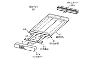
- FIG. 6 is a perspective view showing a configuration example of the battery pack 90 according to the second embodiment.
- FIG. 7 is an exploded perspective view showing the structure of the battery cell 80.
- FIG. 8 is a top view and a side view showing a state in the middle of manufacturing of the battery cell 80 according to the second embodiment.
- FIG. 9 is a sectional view showing a sectional structure of the battery cell 80.
- the battery pack 90 is, for example, a battery pack of a nonaqueous electrolyte battery having a square shape or a flat shape, and as shown in FIG. 6, both ends are opened to form an opening, and a wound electrode is formed in the exterior material.
- the battery cell 80 in which the body 50 is accommodated, and the top cover 82a and the bottom cover 82b each fitted to the opening of the both ends of the battery cell 80 are provided.
- the wound electrode body 50 accommodated in the battery pack 90 can use the same wound electrode body 50 as in the first embodiment.
- the positive electrode lead 51 and the negative electrode lead 52 connected to the wound electrode body 50 are led out from the fused portion of the exterior material via the adhesion film 61, and the positive electrode lead 51 and the negative electrode lead 52 are connected. Are connected to the circuit board 81.
- the exterior material has a plate shape as a whole, and has a rectangular shape when viewed from the surface direction, and the length in the side portion direction than the hard laminate film 83. Consists of a soft laminate film 85 having a short rectangular shape.
- the opening at both ends of the battery cell 80 has a rectangular shape as a whole, and both short sides swell outwardly to form an elliptical arc.
- the battery cell 80 includes a soft laminate film 85 provided with a recess 86, a wound electrode body 50 accommodated in the recess 86, and a hard provided so as to cover the opening of the recess 86 that accommodates the wound electrode body 50. It consists of a laminate film 83.
- the hard laminate film 83 is set so that the short sides of both sides come into contact with each other or face each other with a slight gap in a state where the recess 86 in which the wound electrode body 50 is housed is wrapped.
- a cutout portion 84 may be provided on the long side of the top side of the hard laminate film 83.
- the notches 84 are provided so as to be located on both short sides when viewed from the front of the battery cell 80. By providing the notch portion 84, the top cover 82a can be easily fitted.
- the positive electrode lead 51 and the negative electrode lead 52 electrically connected to the positive electrode 53 and the negative electrode 54 of the wound electrode body 50 respectively. Has been derived.
- the top cover 82a and the bottom cover 82b have shapes that can be fitted into openings at both ends of the battery cell 80. Specifically, when viewed from the front, the top cover 82a and the bottom cover 82b have a rectangular shape as a whole, and both short sides thereof are It swells to form an elliptical arc toward the outside. Note that the front indicates a direction in which the battery cell 80 is viewed from the top side.
- this exterior material covers a soft laminate film 85 provided with a recess 86 for housing the wound electrode body 50, and covers the recess 86 on the soft laminate film 85. And a hard laminate film 83 stacked on top of each other.
- the soft laminate film 85 has the same configuration as that of the exterior member 60 in the first embodiment.
- the soft laminate film 85 is characterized in that a soft metal material such as annealed aluminum (JIS A8021P-O) or (JIS A8079P-O) is used as the metal layer.
- a soft metal material such as annealed aluminum (JIS A8021P-O) or (JIS A8079P-O) is used as the metal layer.
- the soft laminate film 85 has a function of maintaining the shape after bending and withstanding deformation from the outside. For this reason, a hard metal material such as aluminum (Al), stainless steel (SUS), iron (Fe), copper (Cu), or nickel (Ni) is used as the metal layer, and in particular, a hard material without annealing treatment. It is characterized in that aluminum (JIS A3003P-H18) or (JIS A3004P-H18) or austenitic stainless steel (SUS304) is used.
- a hard metal material such as aluminum (Al), stainless steel (SUS), iron (Fe), copper (Cu), or nickel (Ni) is used as the metal layer, and in particular, a hard material without annealing treatment. It is characterized in that aluminum (JIS A3003P-H18) or (JIS A3004P-H18) or austenitic stainless steel (SUS304) is used.
- the wound electrode body 50 can have the same configuration as in the first embodiment. Moreover, you may use the laminated electrode body 70 demonstrated in the other example of 1st Embodiment.
- Nonaqueous electrolyte, gel electrolyte layer The gel electrolyte layer formed between the positive electrode 53 and the separator 55 and between the negative electrode 54 and the separator 55 can have the same configuration as the gel electrolyte layer of the first embodiment.
- the separator 55 is the same as that in the first embodiment.
- the circuit board 81 is one in which the positive electrode lead 51 and the negative electrode lead 52 of the wound electrode body 50 are electrically connected.
- the circuit board 81 is mounted with a protection circuit including a temperature protection element such as a fuse, a thermal resistance element (Positive Temperature Coefficient; PTC element), a thermistor, etc., and an ID resistor for identifying the battery pack. (For example, three) contact portions are formed.
- the protection circuit is provided with a charge / discharge control FET (Field Effect Transistor), an IC (Integrated Circuit) for monitoring the battery cell 80 and controlling the charge / discharge control FET, and the like.
- the thermal resistance element is connected in series with the wound electrode body, and when the temperature of the battery becomes higher than the set temperature, the electrical resistance increases rapidly and substantially blocks the current flowing through the battery.
- the fuse is also connected in series with the wound electrode body, and when an overcurrent flows through the battery, it is blown by its own current to cut off the current.
- a heater resistor is provided in the vicinity of the fuse. When an overvoltage is applied, the temperature of the heater resistor rises, so that the current is cut off.
- the battery cell 80 when the terminal voltage of the battery cell 80 becomes higher than the charge prohibition voltage higher than the full charge voltage, the battery cell 80 may be in a dangerous state such as heat generation and ignition. For this reason, the protection circuit monitors the voltage of the battery cell 80, and when the battery cell 80 reaches the charge prohibition voltage, the charge control FET is turned off to prohibit charging. Furthermore, when the terminal voltage of the battery cell 80 is over-discharged to a voltage lower than the discharge inhibition voltage and the battery cell 80 voltage becomes 0 V, the battery cell 80 may be in an internal short circuit state and may not be recharged. For this reason, when the battery cell 80 voltage is monitored and the discharge inhibition voltage is reached, the discharge control FET is turned off to inhibit discharge.
- the top cover 82a is fitted into the top side opening of the battery cell 80, and a side wall for fitting into the top side opening is provided along part or all of the outer periphery of the top cover 82a. .
- the battery cell 80 and the top cover 82a are bonded by heat-sealing the side wall of the top cover 82a and the inner surface of the end of the hard laminate film 83.
- the circuit board 81 is accommodated in the top cover 82a.
- the top cover 82a is provided with a plurality of openings at positions corresponding to the contact portions so that the plurality of contact portions of the circuit board 81 are exposed to the outside.
- the contact portion of the circuit board 81 contacts the electronic device through the opening of the top cover 82a. Thereby, the battery pack 90 and the electronic device are electrically connected.
- Such a top cover 82a is produced in advance by injection molding.
- the bottom cover 82b is fitted into the bottom opening of the battery cell 80, and a side wall for fitting into the bottom opening is provided along a part or all of the outer periphery of the bottom cover 82b. .
- the battery cell 80 and the bottom cover 82b are bonded by heat-sealing the side wall of the bottom cover 82b and the inner surface of the end of the hard laminate film 83.
- Such a bottom cover 82b is produced in advance by injection molding. It is also possible to use a method in which the battery cell 80 is installed in a mold and a hot melt resin is poured into the bottom portion so as to be molded integrally with the battery cell 80.
- the wound electrode body 50 is accommodated in the recess 86 of the soft laminate film 85, and the hard laminate film 83 is disposed so as to cover the recess 86.
- the hard laminate film 83 and the soft laminate film 85 are disposed so that the inner resin layer of the hard laminate film 83 and the inner resin layer of the soft laminate film 85 face each other.
- the hard laminate film 83 and the soft laminate film 85 are sealed along the periphery of the recess 86.
- the sealing is performed by using a metal heater head (not shown) and thermally fusing the inner resin layer of the hard laminate film 83 and the inner resin layer of the soft laminate film 85 while reducing the pressure.
- the wound electrode body 50 may be formed by previously forming a gel electrolyte on both surfaces of the positive electrode and the negative electrode.
- the hard laminate film 83 is deformed so that the short sides of the hard laminate film 83 are in contact with each other.
- an adhesive film 87 made of a resin material having high adhesion to both the inner resin layer of the hard laminate film 83 and the outer resin layer of the soft laminate film 85 is provided. insert.
- the inner resin layer of the hard laminate film 83 and the outer resin layer of the soft laminate film 85 are heat-sealed by heating the one surface of the hard laminate film 83 where the short side seam is located with a heater head.
- the battery cell 80 is obtained.
- an adhesive layer made of a resin having high adhesiveness with the outer resin layer of the soft laminate film 85 may be provided on the surface of the inner resin layer of the hard laminate film 83 and heat-sealed. Good.
- the fitting portions of the top cover 82a and the bottom cover 82b are respectively heated by the heater head, and the top cover 82a and the bottom cover 82b and the inner resin layer of the hard laminate film 83 are heat-sealed. Thereby, the battery pack 90 is produced.
- FIG. 10 is a block diagram illustrating a circuit configuration example when the nonaqueous electrolyte battery of the present technology is applied to a battery pack.
- the battery pack includes a switch unit 304 including an assembled battery 301, an exterior, a charge control switch 302a, and a discharge control switch 303a, a current detection resistor 307, a temperature detection element 308, and a control unit 310.
- the battery pack also includes a positive electrode terminal 321 and a negative electrode terminal 322.
- the positive electrode terminal 321 and the negative electrode terminal 322 are connected to the positive electrode terminal and the negative electrode terminal of the charger, respectively, and charging is performed. Further, when the electronic device is used, the positive electrode terminal 321 and the negative electrode terminal 322 are connected to the positive electrode terminal and the negative electrode terminal of the electronic device, respectively, and discharge is performed.
- the assembled battery 301 is formed by connecting a plurality of nonaqueous electrolyte batteries 301a in series and / or in parallel.
- This nonaqueous electrolyte battery 301a is a nonaqueous electrolyte battery of the present technology.
- 2P3S 2 parallel 3 series
- n parallel m series (n and m are integers). As such, any connection method may be used.
- the switch unit 304 includes a charge control switch 302a and a diode 302b, and a discharge control switch 303a and a diode 303b, and is controlled by the control unit 310.
- the diode 302b has a reverse polarity with respect to the charging current flowing from the positive terminal 321 in the direction of the assembled battery 301 and the forward polarity with respect to the discharging current flowing from the negative terminal 322 in the direction of the assembled battery 301.
- the diode 303b has a forward polarity with respect to the charging current and a reverse polarity with respect to the discharging current.
- the switch portion is provided on the + side, but may be provided on the ⁇ side.
- the charge control switch 302a is turned off when the battery voltage becomes the overcharge detection voltage, and is controlled by the charge / discharge control unit so that the charge current does not flow in the current path of the assembled battery 301. After the charge control switch is turned off, only discharging is possible through the diode 302b. Further, it is turned off when a large current flows during charging, and is controlled by the control unit 310 so that the charging current flowing in the current path of the assembled battery 301 is cut off.
- the discharge control switch 303 a is turned off when the battery voltage becomes the overdischarge detection voltage, and is controlled by the control unit 310 so that the discharge current does not flow in the current path of the assembled battery 301. After the discharge control switch 303a is turned off, only charging is possible via the diode 303b. Further, it is turned off when a large current flows during discharging, and is controlled by the control unit 310 so as to cut off the discharging current flowing in the current path of the assembled battery 301.
- the temperature detection element 308 is, for example, a thermistor, is provided in the vicinity of the assembled battery 301, measures the temperature of the assembled battery 301, and supplies the measured temperature to the control unit 310.
- the voltage detection unit 311 measures the voltage of the assembled battery 301 and each non-aqueous electrolyte battery 301 a that constitutes the same, performs A / D conversion on the measured voltage, and supplies the voltage to the control unit 310.
- the current measurement unit 313 measures the current using the current detection resistor 307 and supplies this measurement current to the control unit 310.
- the switch control unit 314 controls the charge control switch 302a and the discharge control switch 303a of the switch unit 304 based on the voltage and current input from the voltage detection unit 311 and the current measurement unit 313.
- the switch control unit 314 sends a control signal to the switch unit 304 when any voltage of the nonaqueous electrolyte battery 301a becomes equal to or lower than the overcharge detection voltage or overdischarge detection voltage, or when a large current flows suddenly. To prevent overcharge, overdischarge and overcurrent charge / discharge.
- the overcharge detection voltage is, for example, 4.20V ⁇ 0.05V is determined, and the overdischarge detection voltage is determined to be, for example, 2.4V ⁇ 0.1V.
- the charge / discharge switch for example, a semiconductor switch such as a MOSFET can be used.
- the parasitic diode of the MOSFET functions as the diodes 302b and 303b.
- the switch control unit 314 supplies control signals DO and CO to the gates of the charge control switch 302a and the discharge control switch 303a, respectively.
- the charge control switch 302a and the discharge control switch 303a are P-channel type, they are turned on by a gate potential that is lower than the source potential by a predetermined value or more. That is, in normal charging and discharging operations, the control signals CO and DO are set to the low level, and the charging control switch 302a and the discharging control switch 303a are turned on.
- control signals CO and DO are set to the high level, and the charge control switch 302a and the discharge control switch 303a are turned off.
- the memory 317 includes a RAM and a ROM, and includes, for example, an EPROM (Erasable Programmable Read Only Memory) that is a nonvolatile memory.
- EPROM Erasable Programmable Read Only Memory
- the numerical value calculated by the control unit 310, the internal resistance value of the battery in the initial state of each nonaqueous electrolyte battery 301a measured in the manufacturing process, and the like are stored in advance, and can be appropriately rewritten. is there.
- the full charge capacity of the nonaqueous electrolyte battery 301a for example, the remaining capacity can be calculated together with the control unit 310.
- the temperature detection unit 318 measures the temperature using the temperature detection element 308, performs charge / discharge control at the time of abnormal heat generation, and performs correction in the calculation of the remaining capacity.
- an electronic device, an electric vehicle, and a power storage device each equipped with the nonaqueous electrolyte battery according to the first embodiment and the battery pack according to the second and third embodiments.
- a device such as an apparatus will be described.
- the nonaqueous electrolyte batteries and battery packs described in the first to third embodiments can be used for supplying power to devices such as electronic devices, electric vehicles, and power storage devices.
- Examples of electronic devices include notebook computers, PDAs (personal digital assistants), mobile phones, cordless phones, video movies, digital still cameras, electronic books, electronic dictionaries, music players, radios, headphones, game machines, navigation systems, Memory card, pacemaker, hearing aid, electric tool, electric shaver, refrigerator, air conditioner, TV, stereo, water heater, microwave oven, dishwasher, washing machine, dryer, lighting equipment, toy, medical equipment, robot, road conditioner, traffic light Etc.
- examples of the electric vehicle include a railway vehicle, a golf cart, an electric cart, an electric vehicle (including a hybrid vehicle), and the like, and these are used as a driving power source or an auxiliary power source.
- Examples of power storage devices include power storage power supplies for buildings such as houses or power generation facilities.
- the first power storage system is a power storage system in which a power storage device is charged by a power generation device that generates power from renewable energy.
- the second power storage system is a power storage system that includes a power storage device and supplies power to an electronic device connected to the power storage device.
- the third power storage system is an electronic device that receives power supply from the power storage device.
- the fourth power storage system includes an electric vehicle having a conversion device that receives power supplied from the power storage device and converts the power into a driving force of the vehicle, and a control device that performs information processing related to vehicle control based on information related to the power storage device. It is.
- the fifth power storage system is a power system that includes a power information transmission / reception unit that transmits / receives signals to / from other devices via a network, and performs charge / discharge control of the power storage device described above based on information received by the transmission / reception unit.
- the sixth power storage system is a power system that receives power from the power storage device described above or supplies power from the power generation device or the power network to the power storage device.
- the power storage system will be described.
- the house 101 is provided with a home power generation device 104, a power consumption device 105, a power storage device 103, a control device 110 that controls each device, a smart meter 107, and a sensor 111 that acquires various types of information.
- Each device is connected by a power network 109 and an information network 112.
- a solar cell, a fuel cell, or the like is used as the home power generation device 104, and the generated power is supplied to the power consumption device 105 and / or the power storage device 103.
- the power consuming device 105 is a refrigerator 105a, an air conditioner 105b, a television receiver 105c, a bath 105d, and the like.
- the electric power consumption device 105 includes an electric vehicle 106.
- the electric vehicle 106 is an electric vehicle 106a, a hybrid car 106b, and an electric motorcycle 106c.
- the nonaqueous electrolyte battery of the present technology is applied to the power storage device 103.
- the nonaqueous electrolyte battery of the present technology may be constituted by, for example, the above-described lithium ion secondary battery.
- the smart meter 107 has a function of measuring the usage amount of commercial power and transmitting the measured usage amount to an electric power company.
- the power network 109 may be one or a combination of DC power supply, AC power supply, and non-contact power supply.
- the various sensors 111 are, for example, human sensors, illuminance sensors, object detection sensors, power consumption sensors, vibration sensors, contact sensors, temperature sensors, infrared sensors, and the like. Information acquired by various sensors 111 is transmitted to the control device 110. Based on the information from the sensor 111, the weather condition, the human condition, etc. can be grasped, and the power consumption device 105 can be automatically controlled to minimize the energy consumption. Furthermore, the control device 110 can transmit information regarding the house 101 to an external power company or the like via the Internet.
- the power hub 108 performs processing such as branching of power lines and DC / AC conversion.
- Communication methods of the information network 112 connected to the control device 110 include a method using a communication interface such as UART (Universal Asynchronous Receiver-Transceiver), wireless communication such as Bluetooth, ZigBee, Wi-Fi, etc.
- a communication interface such as UART (Universal Asynchronous Receiver-Transceiver), wireless communication such as Bluetooth, ZigBee, Wi-Fi, etc.
- Bluetooth method is applied to multimedia communication and can perform one-to-many connection communication.
- ZigBee uses the physical layer of IEEE (Institute of Electrical and Electronics Electronics) (802.15.4).
- IEEE802.15.4 is a name of a short-range wireless network standard called PAN (Personal Area Network) or W (Wireless) PAN.
- the control device 110 is connected to an external server 113.
- the server 113 may be managed by any one of the house 101, the power company, and the service provider.
- the information transmitted and received by the server 113 is, for example, information related to power consumption information, life pattern information, power charges, weather information, natural disaster information, and power transactions. These pieces of information may be transmitted / received from a power consuming device in the home (for example, a television receiver), but may be transmitted / received from a device outside the home (for example, a mobile phone). Such information may be displayed on a device having a display function, such as a television receiver, a mobile phone, or a PDA (Personal Digital Assistants).
- a display function such as a television receiver, a mobile phone, or a PDA (Personal Digital Assistants).
- the control device 110 that controls each unit includes a CPU (Central Processing Unit), a RAM (Random Access Memory), a ROM (Read Only Memory), and the like, and is stored in the power storage device 103 in this example.
- the control device 110 is connected to the power storage device 103, the home power generation device 104, the power consumption device 105, the various sensors 111, the server 113 and the information network 112, and adjusts, for example, the amount of commercial power used and the amount of power generation. It has a function. In addition, you may provide the function etc. which carry out an electric power transaction in an electric power market.
- electric power is generated not only from the centralized power system 102 such as the thermal power generation 102a, the nuclear power generation 102b, and the hydroelectric power generation 102c but also from the home power generation device 104 (solar power generation, wind power generation) to the power storage device 103.
- the home power generation device 104 solar power generation, wind power generation
- the electric power obtained by solar power generation is stored in the power storage device 103, and midnight power with a low charge is stored in the power storage device 103 at night, and the power stored by the power storage device 103 is discharged during a high daytime charge. You can also use it.
- control device 110 is stored in the power storage device 103 .
- control device 110 may be stored in the smart meter 107 or may be configured independently.
- the power storage system 100 may be used for a plurality of homes in an apartment house, or may be used for a plurality of detached houses.
- FIG. 12 schematically shows an example of the configuration of a hybrid vehicle that employs a series hybrid system to which the present technology is applied.
- a series hybrid system is a car that runs on an electric power driving force conversion device using electric power generated by a generator driven by an engine or electric power once stored in a battery.
- the hybrid vehicle 200 includes an engine 201, a generator 202, a power driving force conversion device 203, driving wheels 204a, driving wheels 204b, wheels 205a, wheels 205b, a battery 208, a vehicle control device 209, various sensors 210, and a charging port 211. Is installed.
- the nonaqueous electrolyte battery of the present technology described above is applied to the battery 208.
- Hybrid vehicle 200 travels using electric power / driving force conversion device 203 as a power source.
- An example of the power driving force conversion device 203 is a motor.
- the electric power / driving force converter 203 is operated by the electric power of the battery 208, and the rotational force of the electric power / driving force converter 203 is transmitted to the driving wheels 204a and 204b.
- DC-AC DC-AC
- AC-DC conversion AC-DC conversion
- the power driving force converter 203 can be applied to either an AC motor or a DC motor.
- the various sensors 210 control the engine speed via the vehicle control device 209, and control the opening (throttle opening) of a throttle valve (not shown).
- the various sensors 210 include a speed sensor, an acceleration sensor, an engine speed sensor, and the like.
- the rotational force of the engine 201 is transmitted to the generator 202, and the electric power generated by the generator 202 by the rotational force can be stored in the battery 208.
- the resistance force at the time of deceleration is applied as a rotational force to the power driving force conversion device 203, and the regenerative electric power generated by the power driving force conversion device 203 by this rotational force is used as the battery 208. Accumulated in.
- the battery 208 is connected to a power source external to the hybrid vehicle 200, so that power can be supplied from the external power source using the charging port 211 as an input port, and the received power can be stored.
- an information processing device that performs information processing related to vehicle control based on information related to the nonaqueous electrolyte battery may be provided.
- an information processing apparatus for example, there is an information processing apparatus that displays a battery remaining amount based on information on the remaining amount of the battery.
- the present technology is also effective for a parallel hybrid vehicle in which the engine and motor outputs are both driving sources, and the system is switched between the three modes of driving with only the engine, driving with the motor, and engine and motor. Applicable. Furthermore, the present technology can be effectively applied to a so-called electric vehicle that travels only by a drive motor without using an engine.
- Example 1-1> to ⁇ Example 1-48> and ⁇ Comparative Example 1-1> to ⁇ Comparative Example 1-16> In the following Example 1-1 to Example 1-48 and Comparative Example 1-1 to Comparative Example 1-16, using batteries in which the heat capacity per unit area of the gel electrolyte layer and the heat capacity per unit volume were adjusted, The effect of this technology was confirmed.
- Example 1-1 [Production of positive electrode] A positive electrode mixture obtained by mixing 91% by mass of lithium cobaltate (LiCoO 2 ) as a positive electrode active material, 6% by mass of carbon black as a conductive agent, and 3% by mass of polyvinylidene fluoride (PVdF) as a binder.
- the positive electrode mixture was dispersed in N-methyl-2-pyrrolidone (NMP) as a dispersion medium to obtain a positive electrode mixture slurry.
- NMP N-methyl-2-pyrrolidone
- This positive electrode mixture slurry was applied to both surfaces of a positive electrode current collector made of a strip-shaped aluminum foil having a thickness of 12 ⁇ m so that a part of the positive electrode current collector was exposed.
- the dispersion medium of the applied positive electrode mixture slurry was evaporated and dried, and compression-molded with a roll press to form a positive electrode active material layer.
- the positive electrode terminal was attached to the exposed portion of the positive electrode current collector to form the positive electrode.
- coated negative mix slurry was evaporated and dried, and the negative electrode active material layer was formed by compression molding with a roll press. Finally, the negative electrode terminal was attached to the exposed portion of the positive electrode current collector to form a negative electrode.
- EC ethylene carbonate
- PC propylene carbonate
- VC vinylene carbonate
- polyvinylidene fluoride PVdF
- DMC dimethyl carbonate
- the precursor solution was applied to both surfaces of the positive electrode and the negative electrode and dried to remove the plasticizer. Thereby, a gel electrolyte layer was formed on the surfaces of the positive electrode and the negative electrode.
- the inorganic particles or the group of inorganic particles formed into secondary particles are not connected and do not form a lump but are dispersed.
- the boehmite amount per unit area was adjusted by the coating thickness of the precursor solution. Specifically, the thickness is adjusted so that the amount of boehmite per unit area is 0.0005 g / cm 2 on both sides of the positive and negative electrodes, and the total heat capacity per unit area of the gel electrolyte layer is 0.00. 0006 J / Kcm 2 (0.0005 [g / cm 2 ] ⁇ 1.2 [J / gK]).
- the filling amount of boehmite per unit volume was adjusted by the solid content ratio of the resin solution. Specifically, a gel electrolyte layer with a thickness of 7.5 ⁇ m is formed on each surface of the positive electrode and the negative electrode so that boehmite per unit volume is 0.33 g / cm 3 on both sides of the positive electrode and the negative electrode. The total thickness of the gel electrolyte layer between the positive electrode and the negative electrode is adjusted to 15 ⁇ m (0.0005 [g / cm 2 ] ⁇ 0.33 [g / cm 3 ]), and the unit per unit volume of the gel electrolyte layer is adjusted.
- the total heat capacity was 0.4 J / Kcm 3 (0.33 [g / cm 3 ] ⁇ 1.2 [J / gK]).
- a gel electrolyte layer having a heat capacity per unit area of 0.0006 J / Kcm 2 and a heat capacity per unit volume of 0.4 J / Kcm 3 was obtained.
- the positive and negative electrodes with the gel electrolyte layer formed on both sides and the separator are laminated in the order of the positive electrode, the separator, the negative electrode and the separator, wound in a flat shape many times in the longitudinal direction, and then adhered to the end of winding.
- a wound electrode body was formed by fixing with a tape.
- the wound electrode body is covered with a laminate film having a soft aluminum layer, and the lead-out side of the positive electrode terminal and the negative electrode terminal around the wound electrode body and the other two sides are heat-sealed under reduced pressure and sealed. Stopped and sealed.
- a laminated film type battery shown in FIG. 1 having a battery shape of 37 mm in thickness, 49 mm in width, 81 mm in height (374981 size), and a battery capacity of 2000 mAh was produced.
- Example 1-2> to ⁇ Example 1-7> The concentration of the inorganic particles was adjusted so that the heat capacity per unit volume of the gel electrolyte layer became the value shown in Table 1.
- the thermal capacity per unit area is 0.0006J / Kcm 2
- the thermal capacity per unit volume respectively 0.2J / Kcm 3, 0.3J / Kcm 3, 1.0J / Kcm 3, 1.5J / Laminated film type batteries of Examples 1-2 to 1-7 having gel electrolyte layers of Kcm 3 , 2.5 J / Kcm 3 and 3.0 J / Kcm 3 were produced.
- the heat capacity per unit area of the gel electrolyte layer was adjusted according to the coating thickness of the precursor solution. Specifically, heat capacity, respectively 0.0001J / Kcm 2 per unit area of the gel electrolyte layer, 0.0002J / Kcm 2, 0.0010J / Kcm 2, 0.0013J / Kcm 2, 0.0015J / Kcm 2 It was made to become. The concentration of the inorganic particles was adjusted so that the heat capacity per unit volume was 0.4 J / Kcm 3 . Thus, laminated film type batteries of Examples 1-8 to 1-12 were produced.
- Example 1-13> to ⁇ Example 1-24> When forming the negative electrode active material layer, silicon was used instead of graphite as the negative electrode active material.
- a negative electrode mixture was prepared by mixing 85% by mass of silicon (Si) particles as a negative electrode active material, 10% by mass of carbon black as a conductive agent, and 5% by mass of polyvinylidene fluoride (PVdF) as a binder.
- the negative electrode mixture was dispersed in N-methyl-2-pyrrolidone (NMP) as a dispersion medium to obtain a negative electrode mixture slurry.
- NMP N-methyl-2-pyrrolidone
- Laminated film type batteries of Examples 1-13 to 1-24 were produced in the same manner as in Examples 1-1 to 1-12, except that this negative electrode mixture slurry was used.
- a carbon tin composite material was used as the negative electrode active material instead of graphite.
- the carbon-tin composite material contains tin (Sn), cobalt (Co), and carbon (C) as constituent elements, and the composition is tin content of 22% by mass, cobalt content of 55% by mass, carbon
- An SnCoC-containing material having a content of 23% by mass and a ratio of tin to the total of tin and cobalt (Co / (Sn + Co)) of 71.4% by mass was used.
- a negative electrode mixture was prepared by mixing 80% by mass of SnCoC-containing material powder as a negative electrode active material, 12% by mass of graphite as a conductive agent, and 8% by mass of polyvinylidene fluoride (PVdF) as a binder. Subsequently, the negative electrode mixture was dispersed in N-methyl-2-pyrrolidone to prepare a paste-like negative electrode mixture slurry. Laminated film type batteries of Examples 1-25 to 1-36 were produced in the same manner as in Examples 1-1 to 1-12, except that this negative electrode mixture slurry was used.
- lithium titanate (Li 4 Ti 5 O 12 ) was used as the negative electrode active material instead of graphite.
- a negative electrode mixture prepared by mixing 85% by mass of lithium titanate (Li 4 Ti 5 O 12 ) as a negative electrode active material, 10% by mass of graphite as a conductive agent, and 5% by mass of polyvinylidene fluoride (PVdF) as a binder. It was. Subsequently, the negative electrode mixture was dispersed in N-methyl-2-pyrrolidone to prepare a paste-like negative electrode mixture slurry. Laminated film type batteries of Examples 1-37 to 1-48 were produced in the same manner as in Examples 1-1 to 1-12 except that this negative electrode mixture slurry was used.
- Comparative Example 1-1 A laminated film type battery of Comparative Example 1-1 was produced in the same manner as in Example 1-1 except that the inorganic particles were not mixed in the precursor solution and a gel electrolyte layer containing no inorganic particles was formed.
- Comparative Example 1-2 A laminated film type battery of Comparative Example 1-2 was prepared in the same manner as in Example 1-1 except that the coating amount of the precursor solution was adjusted so that the heat capacity per unit area of the gel electrolyte layer was 0.00005 J / Kcm 2. Produced.
- Comparative Example 1-3 A laminated film type battery of Comparative Example 1-3 was produced in the same manner as Example 1-1 except that the boehmite concentration was adjusted so that the heat capacity per unit volume of the gel electrolyte layer was 3.5 J / Kcm 2 . .
- Comparative Example 1-5 A laminated film type battery of Comparative Example 1-5 was produced in the same manner as Comparative Example 1-1 except that silicon was used as the negative electrode active material and the negative electrode mixture slurry had the same configuration as in Example 1-13.
- Comparative Example 1-6 to Comparative Example are the same as Comparative Example 1-2 to Comparative Example 1-4, except that silicon is used as the negative electrode active material and the negative electrode mixture slurry has the same configuration as that of Example 1-13. 1-8 laminated film type batteries were produced.
- Comparative Example 1-9 A laminated film type battery of Comparative Example 1-9 was prepared in the same manner as Comparative Example 1-1 except that a carbon tin composite material was used as the negative electrode active material and the negative electrode mixture slurry had the same configuration as in Example 1-37. Produced.
- Comparative Example 1-10 is the same as Comparative Example 1-2 to Comparative Example 1-4 except that a carbon-tin composite material is used as the negative electrode active material and the negative electrode mixture slurry has the same configuration as that of Example 1-25. -Laminated film type batteries of Comparative Examples 1-12 were produced.
- Comparative Example 1 was the same as Comparative Example 1-1 except that lithium titanate (Li 4 Ti 5 O 12 ) was used as the negative electrode active material, and the negative electrode mixture slurry had the same configuration as Example 1-37. 1 laminate film type battery was produced.
- lithium titanate Li 4 Ti 5 O 12
- Example 1'-1> Instead of boehmite as endothermic particles, talc (specific heat: 1.1 J / gK, specific gravity: 2.70 g / cm 3 ), which is inorganic particles, was used.
- the amount of talc per unit area was adjusted by the coating thickness of the precursor solution. Specifically, the thickness is adjusted so that the amount of talc per unit area is 0.0005 g / cm 2 on both sides of the positive electrode and the negative electrode, and the total heat capacity per unit area of the gel electrolyte layer is 0.00. 0006 J / Kcm 2 (0.00055 [g / cm 2 ] ⁇ 1.1 [J / gK]).
- the filling amount of talc per unit volume was adjusted by the solid content ratio of the resin solution.
- the gel electrolyte layer is formed on each surface of the positive electrode and the negative electrode with a thickness of 7.6 ⁇ m so that the talc per unit volume is 0.36 g / cm 3 on both sides of the positive electrode and the negative electrode.
- the total thickness of the gel electrolyte layer between the positive electrode and the negative electrode is adjusted to 15.2 ⁇ m (0.00055 [g / cm 2 ] ⁇ 0.36 [g / cm 3 ]), and the unit volume of the gel electrolyte layer is adjusted
- the total heat capacity per unit was 0.4 J / Kcm 3 (0.36 [g / cm 3 ] ⁇ 1.1 [J / gK]).
- a gel electrolyte layer having a heat capacity per unit area of 0.0006 J / Kcm 2 and a heat capacity per unit volume of 0.4 J / Kcm 3 was obtained.
- a laminated film type battery of Example 1′-1 was produced in the same manner as Example 1-1.
- Example 1'-2> to ⁇ Example 1'-7> The concentration of the inorganic particles was adjusted so that the heat capacity per unit volume of the gel electrolyte layer became the value shown in Table 1.
- the thermal capacity per unit area is 0.0006J / Kcm 2
- the thermal capacity per unit volume respectively 0.2J / Kcm 3, 0.3J / Kcm 3, 1.0J / Kcm 3, 1.5J /
- Laminated film type batteries of Example 1′-2 to Example 1′-7 having gel electrolyte layers of Kcm 3 , 2.5 J / Kcm 3 and 3.0 J / Kcm 3 were produced.
- Example 1'-8> to ⁇ Example 1'-12> At the time of applying the precursor solution to the positive electrode and the negative electrode, the heat capacity per unit area of the gel electrolyte layer was adjusted according to the coating thickness of the precursor solution. Specifically, heat capacity, respectively 0.0001J / Kcm 2 per unit area of the gel electrolyte layer, 0.0002J / Kcm 2, 0.0010J / Kcm 2, 0.0013J / Kcm 2, 0.0015J / Kcm 2 It was made to become. The concentration of the inorganic particles was adjusted so that the heat capacity per unit volume was 0.4 J / Kcm 3 . Thus, laminated film type batteries of Example 1′-8 to Example 1′-12 were produced.
- Example 1'-13> to ⁇ Example 1'-24> silicon was used instead of graphite as the negative electrode active material.
- a negative electrode mixture was prepared by mixing 85% by mass of silicon (Si) particles as a negative electrode active material, 10% by mass of carbon black as a conductive agent, and 5% by mass of polyvinylidene fluoride (PVdF) as a binder.
- the negative electrode mixture was dispersed in N-methyl-2-pyrrolidone (NMP) as a dispersion medium to obtain a negative electrode mixture slurry. Except for using this negative electrode mixture slurry, laminate film type batteries of Example 1′-13 to Example 1′-24 were produced in the same manner as Example 1′-1 to Example 1′-12.
- a carbon tin composite material was used as the negative electrode active material instead of graphite.
- the carbon-tin composite material contains tin (Sn), cobalt (Co), and carbon (C) as constituent elements, and the composition is tin content of 22% by mass, cobalt content of 55% by mass, carbon
- An SnCoC-containing material having a content of 23% by mass and a ratio of tin to the total of tin and cobalt (Co / (Sn + Co)) of 71.4% by mass was used.
- a negative electrode mixture was prepared by mixing 80% by mass of SnCoC-containing material powder as a negative electrode active material, 12% by mass of graphite as a conductive agent, and 8% by mass of polyvinylidene fluoride (PVdF) as a binder. Subsequently, the negative electrode mixture was dispersed in N-methyl-2-pyrrolidone to prepare a paste-like negative electrode mixture slurry. Except for using this negative electrode mixture slurry, laminate film type batteries of Example 1'-25 to Example 1'-36 were produced in the same manner as in Example 1'-1 to Example 1'-12.
- PVdF polyvinylidene fluoride
- lithium titanate Li 4 Ti 5 O 12
- a negative electrode mixture prepared by mixing 85% by mass of lithium titanate (Li 4 Ti 5 O 12 ) as a negative electrode active material, 10% by mass of graphite as a conductive agent, and 5% by mass of polyvinylidene fluoride (PVdF) as a binder. It was. Subsequently, the negative electrode mixture was dispersed in N-methyl-2-pyrrolidone to prepare a paste-like negative electrode mixture slurry. Laminated film type batteries of Examples 1′-37 to 1′-48 were produced in the same manner as in Examples 1′-1 to 1′-12 except that this negative electrode mixture slurry was used.
- Comparative Example 1′-1 A laminated film type battery of Comparative Example 1′-1 was produced in the same manner as Example 1′-1 except that the inorganic particles were not mixed in the precursor solution and a gel electrolyte layer containing no inorganic particles was formed.
- Comparative Example 1'-3> A laminated film type battery of Comparative Example 1-3 was produced in the same manner as Example 1-1 except that the talc concentration was adjusted so that the heat capacity per unit volume of the gel electrolyte layer was 3.5 J / Kcm 2 . .
- Comparative Example 1′-5 A laminated film type battery of Comparative Example 1′-5 was prepared in the same manner as Comparative Example 1′-1 except that silicon was used as the negative electrode active material, and the negative electrode mixture slurry had the same structure as Example 1′-13. Produced.
- Comparative Example 1′- is the same as Comparative Example 1′-2 to Comparative Example 1′-4, except that silicon is used as the negative electrode active material and the negative electrode mixture slurry has the same configuration as that of Example 1′-13. Laminated film type batteries of 6 to Comparative Example 1′-8 were produced.
- Comparative Example 1'-9 The laminate film of Comparative Example '1-9 is the same as Comparative Example 1'-1 except that a carbon tin composite material is used as the negative electrode active material and the negative electrode mixture slurry has the same configuration as that of Example 1'-37. A type battery was produced.
- Comparative Example 1'-13 Comparative Example as in Comparative Example 1′-1 except that lithium titanate (Li 4 Ti 5 O 12 ) was used as the negative electrode active material and the negative electrode mixture slurry had the same configuration as in Example 1′-37. A 1′-1 laminate film type battery was produced.
- lithium titanate Li 4 Ti 5 O 12
- the heat capacity per unit area of the gel electrolyte layer is 0.0001 J / Kcm 2 or more and the heat capacity per unit volume is 3.0 J / Kcm 3 or less.
- Example 1-48 and Example 1′-1 to Example 1′-48 it was confirmed that the battery was in a safe state in the short-circuit test.
- the heat capacity per unit area of the gel electrolyte layer is less than 0.0001 J / Kcm 2
- Comparative Example 1-2 and Comparative Example 1′-2 the heat capacity per unit volume of the gel electrolyte layer is 3.0 J / Kcm 3 .
- the batteries were tested in the short circuit test. It turns out to be in danger. It was also found that Comparative Example 1-5 to Comparative Example 1-16 and Comparative Example 1′-5 to Comparative Example 1′-16 were in danger in the short circuit test.
- Example 2-1> to ⁇ Example 2-224> and ⁇ Comparative Example 2-1> the effect of the present technology was confirmed by replacing the endothermic particles constituting the gel electrolyte layer and the resin material.
- Example 2-1 A laminated film type battery of Example 2-1 was produced in the same manner as Example 1-1.
- Example 2-2> A laminate film type battery was produced in the same manner as in Example 2-1, except that polyimide was used instead of polyvinylidene fluoride as the resin material used for the gel electrolyte layer.
- Example 2-3> A laminated film type battery was produced in the same manner as in Example 2-1, except that wholly aromatic polyamide (aramid) was used instead of polyvinylidene fluoride as the resin material used for the gel electrolyte layer.
- wholly aromatic polyamide aramid
- Example 2-4 A laminate film type battery was produced in the same manner as in Example 2-1, except that polyacrylonitrile was used instead of polyvinylidene fluoride as the resin material used for the gel electrolyte layer.
- Example 2-5> A laminate film type battery was produced in the same manner as in Example 2-1, except that polyvinyl alcohol was used instead of polyvinylidene fluoride as the resin material used for the gel electrolyte layer.
- Example 2-6> A laminate film type battery was produced in the same manner as in Example 2-1, except that polyether was used instead of polyvinylidene fluoride as the resin material used for the gel electrolyte layer.
- Example 2-7 A laminated film type battery was produced in the same manner as in Example 2-1, except that an acrylic resin was used instead of polyvinylidene fluoride as the resin material used for the gel electrolyte layer.
- Example 2-8> to ⁇ Example 2-14> A laminated film type battery was prepared in the same manner as in Examples 2-1 to 2-7, except that aluminum nitride (specific heat 0.7 J / gK) was used instead of boehmite as the endothermic particles used in the gel electrolyte layer. Produced.
- the specific heat of aluminum nitride and boehmite is different, and the specific heat of aluminum nitride is smaller than the specific heat of boehmite. Therefore, in order to set the total heat capacity per unit area to 0.0006 J / Kcm 2 , the amount of aluminum nitride per unit area is more than the amount of boehmite per unit area in Examples 2-1 to 2-7. Adjusted by increasing.
- the total heat capacity per unit area of the gel electrolyte layer is 0.0006 J / Kcm 2 (0.00086 [g / cm 2 ] ⁇ 0.7 [J / gK]).
- the application amount of the endothermic particles was adjusted to make the heat capacity per unit area of the gel electrolyte layer constant.
- Example 2-15> to ⁇ Example 2-21> A laminated film type battery was prepared in the same manner as in Examples 2-1 to 2-7, except that boron nitride (specific heat 0.8 J / gK) was used instead of boehmite as the endothermic particles used in the gel electrolyte layer. Produced.
- boron nitride specific heat 0.8 J / gK
- Example 2-22> to ⁇ Example 2-28> A laminated film type battery was obtained in the same manner as Example 2-1 to Example 2-7, except that silicon carbide (specific heat 0.7 J / gK) was used instead of boehmite as the endothermic particles used in the gel electrolyte layer. Produced.
- Example 2-29> to ⁇ Example 2-35> A laminated film type battery was prepared in the same manner as in Examples 2-1 to 2-7, except that talc (specific heat 1.1 J / gK) was used instead of boehmite as the endothermic particles used in the gel electrolyte layer. did.
- Example 2-36> to ⁇ Example 2-42> Laminated film type in the same manner as in Examples 2-1 to 2-7, except that Li 2 O 4 (specific heat 0.8 J / gK) was used instead of boehmite as the endothermic particles used in the gel electrolyte layer. A battery was produced.
- Li 2 O 4 specific heat 0.8 J / gK
- Example 2-43> to ⁇ Example 2-49> Laminated film type in the same manner as in Examples 2-1 to 2-7, except that Li 3 PO 4 (specific heat 0.8 J / gK) was used instead of boehmite as the endothermic particles used in the gel electrolyte layer. A battery was produced.
- Li 3 PO 4 specific heat 0.8 J / gK
- Example 2-50> to ⁇ Example 2-56> A laminated film type battery was prepared in the same manner as in Examples 2-1 to 2-7, except that LiF (specific heat 0.9 J / gK) was used instead of boehmite as the endothermic particles used in the gel electrolyte layer. did.
- LiF specific heat 0.9 J / gK
- Example 2-57> to ⁇ Example 2-63> A laminated film type battery was produced in the same manner as in Examples 2-1 to 2-7, except that diamond (specific heat 0.5 J / gK) was used instead of boehmite as the endothermic particles used in the gel electrolyte layer. did.
- Example 2-64> to ⁇ Example 2-70> A laminated film type battery was prepared in the same manner as in Examples 2-1 to 2-7, except that zirconium oxide (specific heat 0.7 J / gK) was used instead of boehmite as the endothermic particles used in the gel electrolyte layer. Produced.
- zirconium oxide specific heat 0.7 J / gK
- Example 2-71> to ⁇ Example 2-77> A laminated film type battery was obtained in the same manner as in Examples 2-1 to 2-7, except that yttrium oxide (specific heat 0.5 J / gK) was used instead of boehmite as the endothermic particles used in the gel electrolyte layer. Produced.
- yttrium oxide specific heat 0.5 J / gK
- Example 2-78> to ⁇ Example 2-84> Laminated film type battery as in Examples 2-1 to 2-7, except that barium titanate (specific heat 0.8 J / gK) was used instead of boehmite as the endothermic particles used in the gel electrolyte layer. was made.
- barium titanate specific heat 0.8 J / gK
- Example 2-85> to ⁇ Example 2-91> Laminated film type batteries as in Examples 2-1 to 2-7, respectively, except that strontium titanate (specific heat 0.8 J / gK) was used instead of boehmite as the endothermic particles used in the gel electrolyte layer. was made.
- Example 2-92> to ⁇ Example 2-98> A laminated film type battery was prepared in the same manner as in Examples 2-1 to 2-7, except that silicon oxide (specific heat 0.8 J / gK) was used instead of boehmite as the endothermic particles used in the gel electrolyte layer. Produced.
- Example 2-99> to ⁇ Example 2-105> A laminated film type battery was produced in the same manner as in Examples 2-1 to 2-7, except that zeolite (specific heat 1.0 J / gK) was used instead of boehmite as the endothermic particles used in the gel electrolyte layer. did.
- zeolite specific heat 1.0 J / gK
- Example 2-106> to ⁇ Example 2-112> A laminated film type battery was prepared in the same manner as in Examples 2-1 to 2-7, except that barium sulfate (specific heat 0.9 J / gK) was used instead of boehmite as the endothermic particles used in the gel electrolyte layer. Produced.
- Example 2-113> to ⁇ Example 2-119> A laminated film type battery was obtained in the same manner as in Examples 2-1 to 2-7, except that titanium oxide (specific heat 0.8 J / gK) was used instead of boehmite as the endothermic particles used in the gel electrolyte layer. Produced.
- Example 2-120> to ⁇ Example 2-126> A laminated film type battery was obtained in the same manner as in Examples 2-1 to 2-7, except that magnesium oxide (specific heat 1.0 J / gK) was used instead of boehmite as the endothermic particles used in the gel electrolyte layer. Produced.
- magnesium oxide specific heat 1.0 J / gK
- Example 2-127> to ⁇ Example 2-133> A laminated film type battery was produced in the same manner as in Examples 2-1 to 2-7, except that graphite (specific heat 0.8 J / gK) was used instead of boehmite as the endothermic particles used in the gel electrolyte layer. did.
- Example 2-134> to ⁇ Example 2-140> A laminated film type battery was prepared in the same manner as in Examples 2-1 to 2-7, except that carbon nanotubes (specific heat 0.8 J / gK) were used instead of boehmite as the endothermic particles used in the gel electrolyte layer. Produced.
- Example 2-141> to ⁇ Example 2-147> Laminated film type batteries as in Examples 2-1 to 2-7, respectively, except that aluminum hydroxide (specific heat 1.5 J / gK) was used instead of boehmite as the endothermic particles used in the gel electrolyte layer. was made.
- aluminum hydroxide specific heat 1.5 J / gK
- Example 2-148> to ⁇ Example 2-154> A laminated film type battery was obtained in the same manner as in Examples 2-1 to 2-7, except that boron carbide (specific heat 1.0 J / gK) was used instead of boehmite as the endothermic particles used in the gel electrolyte layer. Produced.
- boron carbide specific heat 1.0 J / gK
- Example 2-155> to ⁇ Example 2-161> A laminated film type battery was prepared in the same manner as in Examples 2-1 to 2-7, except that silicon nitride (specific heat 0.7 J / gK) was used instead of boehmite as the endothermic particles used in the gel electrolyte layer. Produced.
- Example 2-162> to ⁇ Example 2-168> A laminated film type battery was prepared in the same manner as in Examples 2-1 to 2-7, except that titanium nitride (specific heat 0.6 J / gK) was used instead of boehmite as the endothermic particles used in the gel electrolyte layer. Produced.
- Example 2-169> to ⁇ Example 2-175> A laminated film type battery was obtained in the same manner as in Examples 2-1 to 2-7, except that zinc oxide (specific heat 0.5 J / gK) was used instead of boehmite as the endothermic particles used in the gel electrolyte layer. Produced.
- Example 2-176> to ⁇ Example 2-182> A laminated film type battery was obtained in the same manner as in Examples 2-1 to 2-7, except that aluminum oxide (specific heat 0.8 J / gK) was used instead of boehmite as the endothermic particles used in the gel electrolyte layer. Produced.
- aluminum oxide specific heat 0.8 J / gK
- Example 2-183> to ⁇ Example 2-189> Laminated film batteries as in Examples 2-1 to 2-7, respectively, except that olivine (specific heat 0.8 J / gK) was used instead of boehmite as the endothermic particles used in the gel electrolyte layer. was made.
- Example 2-190> to ⁇ Example 2-196> A laminated film type battery was prepared in the same manner as in Examples 2-1 to 2-7, except that montmorillonite (specific heat 0.7 J / gK) was used instead of boehmite as the endothermic particles used in the gel electrolyte layer. did.
- Example 2-197> to ⁇ Example 2-203> A laminated film type battery was produced in the same manner as in Examples 2-1 to 2-7, except that zeolite (specific heat 0.6 J / gK) was used instead of boehmite as the endothermic particles used in the gel electrolyte layer. did.
- zeolite specific heat 0.6 J / gK
- Example 2-204> to ⁇ Example 2-210> A laminated film type battery was produced in the same manner as in Examples 2-1 to 2-7, except that mullite (specific heat 0.8 J / gK) was used instead of boehmite as the endothermic particles used in the gel electrolyte layer. did.
- mullite specific heat 0.8 J / gK
- Example 2-211> to ⁇ Example 2-217> A laminated film type battery was prepared in the same manner as in Examples 2-1 to 2-7, except that kaolinite (specific heat 0.7 J / gK) was used instead of boehmite as the endothermic particles used in the gel electrolyte layer. Produced.
- kaolinite specific heat 0.7 J / gK
- Example 2-218> to ⁇ Example 2-224> A laminated film type battery was prepared in the same manner as in Examples 2-1 to 2-7, except that imogolite (specific heat 0.8 J / gK) was used instead of boehmite as the endothermic particles used in the gel electrolyte layer. did.
- imogolite specific heat 0.8 J / gK
- Comparative Example 2-1 A laminated film type battery of Comparative Example 2-1 was produced in the same manner as in Example 2-1, except that a gel electrolyte layer containing no inorganic particles was formed without mixing inorganic particles in the precursor solution.
- the total heat capacity per unit area of the gel electrolyte layer is 0.0006 J / Kcm 2
- the total heat capacity per unit volume is 0.4 J / Kcm 3 .
- the heat generation temperature in the short-circuit test was as low as 80 ° C. or less, and the safety was high.
- the negative electrode mixture slurry for forming the negative electrode active material layer had the same composition as in Example 1-13.
- the total heat capacity per unit area of the gel electrolyte layer is 0.0006 J / Kcm 2
- the total heat capacity per unit volume is 0.4 J / Kcm 3 .
- Example 4 was carried out in the same manner as Example 2-1 to Example 224 and Comparative Example 2-1, except that the same carbon tin composite material as in Example 1-25 was used instead of graphite as the negative electrode active material. -1 to Example 4-224 and Comparative film 4-1 were produced respectively.
- the negative electrode mixture slurry for forming the negative electrode active material layer had the same composition as in Example 1-25.
- the total heat capacity per unit area of the gel electrolyte layer is 0.0006 J / Kcm 2
- the total heat capacity per unit volume is 0.4 J / Kcm 3 .
- Example 5 was repeated in the same manner as in Examples 2-1 to 2-224 and Comparative Example 2-1, except that the same lithium titanate as in Example 1-37 was used instead of graphite as the negative electrode active material.
- Laminated film type batteries of 1 to Example 224 and Comparative Example 4-1 were produced.
- the negative electrode mixture slurry for forming the negative electrode active material layer had the same composition as in Example 1-37.
- the total heat capacity per unit area of the gel electrolyte layer is 0.0006 J / Kcm 2
- the total heat capacity per unit volume is 0.4 J / Kcm 3 .
- the heat generation temperature in the short-circuit test was as low as less than 80 ° C. and safety was high.
- Example 6-1 A laminated film type battery similar to that of Example 1-1 was produced, and a gel electrolyte layer having a thickness of 7.5 ⁇ m on one side was formed on both sides of a 9 ⁇ m polyethylene microporous film (referred to as both sides of the substrate in Table 6).
- a laminated film type battery of Example 6-1 was obtained. That is, a laminate film type battery of Example 6-1 was obtained by forming a positive electrode and a separator, and a gel electrolyte layer formed between the negative electrode and the separator.
- Example 6-2> The same precursor solution as in Example 1-1 was applied only on both sides of the positive electrode, and the plasticizer was removed by drying to remove the plasticizer side surface of the 9 ⁇ m-thick polyethylene microporous film (the positive electrode during battery production). A gel electrolyte layer having a single-sided thickness of 15 ⁇ m was formed only on the surface opposite to the surface; That is, the gel electrolyte layer was formed only between the positive electrode and the separator.
- a laminated film type battery was produced in the same manner as in Example 6-1 except for the above.
- Example 6-3> The same precursor solution as in Example 1-1 was applied only on both sides of the negative electrode, and the plasticizer was removed by drying, whereby the negative electrode side surface of the 9 ⁇ m-thick polyethylene microporous film (the negative electrode during battery production) The gel electrolyte layer having a single-sided thickness of 15 ⁇ m was formed only on the surface facing the surface; That is, the gel electrolyte layer was formed only between the positive electrode and the separator. Except for the above, a laminated film type battery was produced in the same manner as in Example 6-1.
- Examples 6-4 to 6 are similar to Examples 6-1 to 6-3 except that silicon is used as the negative electrode active material and the negative electrode mixture slurry has the same configuration as that of Example 1-13. 6-6 laminated film type batteries were respectively produced.
- Example 6-7 was carried out in the same manner as Example 6-1 to Example 6-3, except that a carbon tin composite material was used as the negative electrode active material and the negative electrode mixture slurry had the same structure as in Example 1-25. -Laminated film type batteries of Examples 6-9 were prepared.
- Example 6-10> to ⁇ Example 6-12> Example 6-10 to Example 6-10 to Example 6-3 except that lithium titanate was used as the negative electrode active material and the negative electrode mixture slurry had the same configuration as that of Example 1-37.
- the laminated film type batteries of Examples 6-12 were produced.
- Example 6-13> The configuration of each of the positive electrode, the negative electrode, the separator, and the gel electrolyte layer was the same as in Example 6-1, and a laminated film type battery in which the laminated electrode body was packaged with a soft laminated film was produced. That is, the battery configuration was a laminate film for the battery exterior, a laminated type for the electrode body, and graphite for the negative electrode active material.
- the laminated electrode body was covered with a laminate film having a soft aluminum layer, and the lead-out side of the positive electrode terminal and the negative electrode terminal around the laminated electrode body and the other three sides were heat-sealed and sealed, and sealed. .
- a laminated film type battery shown in FIG. 5 having a battery shape of 37 mm in thickness, 49 mm in width, 84 mm in height (374984 size), and a battery capacity of 2000 mAh was produced.
- Example 6-14> to ⁇ Example 6-24> The laminated film type of Examples 6-14 to 6-24 was the same as Example 6-2 to Example 6-12, except that the battery configuration was the same as the laminated film type battery as in Example 6-13. Each battery was produced.
- Example 6-25> The configuration of each of the positive electrode, the negative electrode, the separator, and the gel electrolyte layer was the same as in Example 6-1, and a laminated film type battery in which the wound electrode body was packaged with a soft laminate film was produced. That is, the battery configuration was a laminate film for the battery exterior, a flat wound type for the electrode body, and graphite for the negative electrode active material.
- the separator was a polyethylene microporous film having a thickness of 9 ⁇ m.
- Example 6-1 Assembly of laminated film type battery
- the same precursor solution as in Example 6-1 was applied to both surfaces of the positive electrode and the negative electrode, dried to remove the plasticizer, and a gel electrolyte layer was formed on the surfaces of the positive electrode and the negative electrode.
- the positive electrode, the negative electrode, and the separator are laminated in the order of the positive electrode (the gel electrolyte layer is formed on both sides), the separator, the negative electrode (the gel electrolyte layer is formed on both sides), and the separator in the longitudinal direction.
- the wound electrode body was formed by fixing the wound end portion with an adhesive tape.
- the wound electrode body is covered with a soft laminate film having a soft aluminum layer and a hard laminate film having a hard aluminum layer, and the positive electrode terminal and the negative electrode terminal around the wound electrode body are covered.
- the lead-out side and the other three sides were heat-sealed under reduced pressure and sealed and sealed.
- both ends of the hard laminate film are molded into an elliptical cross section so that the short sides of the hard laminate film are in contact with each other, and the opposing portions of the hard laminate film and the soft laminate film are attached to the battery cell. did.
- the positive electrode lead connected to the positive electrode and the negative electrode lead connected to the negative electrode were connected to the circuit board, and the circuit board was accommodated in the top cover.
- the top cover and the bottom cover are respectively inserted and bonded to the battery cell, the battery shape is 37 mm thick, 49 mm wide, 87 mm high (3749877 size), and the battery capacity is 2000 mAh. A type battery was produced.
- Example 6-26> to ⁇ Example 6-36> The laminated film type of Examples 6-26 to 6-36 is the same as Example 6-2 to Example 6-12 except that the battery configuration is the same as the laminated film type battery as in Example 6-25. Each battery was produced.
- Example 6'-1 A laminated film type battery similar to that of Example 1′-1 was prepared, and a gel electrolyte layer having a thickness of 7.6 ⁇ m on one side was formed on both sides of a 9 ⁇ m polyethylene microporous film (referred to as both sides of the substrate in Table 6).
- the laminated film type battery of Example 6′-1 thus formed was obtained. That is, a laminate film type battery of Example 6′-1 was obtained by forming a positive electrode and a separator, and a gel electrolyte layer formed between the negative electrode and the separator.
- Example 6'-2> The same precursor solution as in Example 1′-1 was applied only to both sides of the positive electrode, and dried to remove the plasticizer, thereby allowing the positive electrode side surface of the 9 ⁇ m-thick polyethylene microporous film (at the time of battery preparation).
- a gel electrolyte layer having a one-side thickness of 15.2 ⁇ m was formed only on the surface facing the positive electrode (referred to as the positive electrode side surface of the base material in Table 6). That is, the gel electrolyte layer was formed only between the positive electrode and the separator.
- a laminate film type battery was produced in the same manner as in Example 6′-1 except for the above.
- Example 6'-3> The same precursor solution as in Example 1′-1 was applied only to both sides of the negative electrode, and dried to remove the plasticizer, thereby removing the negative electrode side surface of the 9 ⁇ m-thick polyethylene microporous film (at the time of battery preparation).
- a gel electrolyte layer having a thickness of 15.2 ⁇ m on one side was formed only on the surface facing the negative electrode (referred to as the negative electrode side surface of the base material in Table 6). That is, the gel electrolyte layer was formed only between the positive electrode and the separator.
- a laminated film type battery was produced in the same manner as in Example 6′-1.
- Example 6′ ⁇ was the same as Example 6′-1 to Example 6′-3, except that silicon was used as the negative electrode active material and the negative electrode mixture slurry had the same structure as Example 1′-13.
- the laminated film type batteries of 4 to Example 6′-6 were produced.
- Example 6 Similar to Example 6'-1 to Example 6'-3, except that a carbon tin composite material was used as the negative electrode active material, and the negative electrode mixture slurry had the same configuration as Example 1'-25 Laminated film type batteries of 6′-7 to Example 6′-9 were produced.
- Example 6 was carried out in the same manner as in Example 6'-1 to Example 6'-3, except that lithium titanate was used as the negative electrode active material, and the negative electrode mixture slurry had the same structure as in Example 1'-37.
- the laminate film type batteries of “ ⁇ 10 to Example 6” -12 were produced.
- Example 6'-13> The configuration of each of the positive electrode, the negative electrode, the separator, and the gel electrolyte layer was the same as in Example 6′-1, and a laminated film type battery in which the laminated electrode body was packaged with a soft laminated film was produced. That is, the battery configuration was a laminate film for the battery exterior, a laminated type for the electrode body, and graphite for the negative electrode active material.
- the laminated electrode body was covered with a laminate film having a soft aluminum layer, and the lead-out side of the positive electrode terminal and the negative electrode terminal around the laminated electrode body and the other three sides were heat-sealed and sealed, and sealed. .
- a laminated film type battery shown in FIG. 5 having a battery shape of 37 mm in thickness, 49 mm in width, 84 mm in height (374984 size), and a battery capacity of 2000 mAh was produced.
- Example 6'-14> to ⁇ Example 6'-24> Example 6'-14 to Example 6'- The same as Example 6'-2 to Example 6'-12, except that the battery configuration was the same as the laminated film type battery as in Example 6'-13. Twenty-four laminate film type batteries were produced.
- Example 6'-25> The configuration of each of the positive electrode, the negative electrode, the separator, and the gel electrolyte layer was the same as in Example 6′-1, and a laminated film type battery in which the wound electrode body was packaged with a soft laminate film was produced. That is, the battery configuration was a laminate film for the battery exterior, a flat wound type for the electrode body, and graphite for the negative electrode active material.
- the separator was a polyethylene microporous film having a thickness of 9 ⁇ m.
- Example 6′-1 Assembly of laminated film type battery
- the same precursor solution as in Example 6′-1 was applied to both the positive electrode and the negative electrode, dried to remove the plasticizer, and a gel electrolyte layer was formed on the surfaces of the positive electrode and the negative electrode.
- the positive electrode, the negative electrode, and the separator are laminated in the order of the positive electrode (the gel electrolyte layer is formed on both sides), the separator, the negative electrode (the gel electrolyte layer is formed on both sides), and the separator in the longitudinal direction.
- the wound electrode body was formed by fixing the wound end portion with an adhesive tape.
- the wound electrode body is covered with a soft laminate film having a soft aluminum layer and a hard laminate film having a hard aluminum layer, and the positive electrode terminal and the negative electrode terminal around the wound electrode body are covered.
- the lead-out side and the other three sides were heat-sealed under reduced pressure and sealed and sealed.
- both ends of the hard laminate film are molded into an elliptical cross section so that the short sides of the hard laminate film are in contact with each other, and the opposing portions of the hard laminate film and the soft laminate film are attached to the battery cell. did.
- the positive electrode lead connected to the positive electrode and the negative electrode lead connected to the negative electrode were connected to the circuit board, and the circuit board was accommodated in the top cover.
- the top cover and the bottom cover are respectively inserted and bonded to the battery cell, the battery shape is 37 mm thick, 49 mm wide, 87 mm high (3749877 size), and the battery capacity is 2000 mAh. A type battery was produced.
- Example 6'-26> to ⁇ Example 6'-36> Example 6'-26 to Example 6'- The same as Example 6'-2 to Example 6'-12, except that the battery configuration was the same as the laminated film type battery as in Example 6'-25. Thirty-six laminated film type batteries were produced.
- the battery equipped with the gel electrolyte layer prepared so that the total heat capacity per unit area is 0.0006 J / Kcm 2 and the total heat capacity per unit volume is 0.4 J / Kcm 3 .
- the heat generation temperature in the short circuit test was as low as 80 ° C. or less, and the safety was high.
- a gel electrolyte layer is provided both between the positive electrode and the separator and between the negative electrode and the separator. Batteries were the safest.
- a gel electrolyte layer is provided between the positive electrode and the separator or between the negative electrode and the separator, a gel electrolyte layer is provided between the negative electrode and the separator, rather than a gel electrolyte layer provided between the positive electrode and the separator. Was found to be more effective.
- Example 7-1> to ⁇ Example 7-94> ⁇ Example 7-1>
- the ratio of the particle shape (“long axis length” / "short axis length”) was determined as follows. Fifty particles were randomly selected, and each selected inorganic particle was observed three-dimensionally with a scanning electron microscope.
- a laminated film type battery was produced in the same manner as in Example 7-1.
- a laminated film type battery was produced in the same manner as in Example 7-1.
- a laminated film type battery was produced in the same manner as in Example 7-1.
- a laminated film type battery was produced in the same manner as in Example 7-1.
- a laminated film type battery was produced in the same manner as in Example 7-1.
- the thickness of the gel electrolyte layer and the composition of each material may be set according to the configuration of the positive electrode and the negative electrode.
- the nonaqueous electrolyte battery may be a primary battery.
- the battery structure is.
- the case of the laminate film type the case where the electrode body has a wound structure or a laminated structure has been described as an example, but the present invention is not limited thereto.
- the electrolyte layer of the present technology can be similarly applied to a case where the battery layer has another battery structure such as a cylindrical shape, a coin shape, a square shape, or a button shape.
- first to third examples of other electrolyte layers composed of the following electrolytes may be used.
- a solid-state material including endothermic particles, an ion conductive polymer material, and an electrolyte salt, and having an ion conductivity by the ion conductive polymer material and the electrolyte salt.
- a solid electrolyte layer made of an electrolyte may be used.
- the ion conductive polymer material include polyether, polyester, polyphosphazene, and polysiloxane.
- a solid electrolyte layer including a heat-absorbing particle and an ion conductive polymer material, and a solid electrolyte having ion conductivity by the polymer material may be used.
- a solid electrolyte layer including a solid electrolyte containing endothermic particles and an ion conductive inorganic material and having an ion conductivity by the inorganic material may be used.
- the ion conductive inorganic material include ion conductive ceramics, ion conductive crystals, and ion conductive glass.
- the heat capacity per unit area of the electrolyte layer is 0.0001 J / Kcm 2 or more and the heat capacity per unit volume is 3.0 J / Kcm 3 or less.
- this technique can also take the following structures.
- a separator provided between the positive electrode and the negative electrode; The battery according to [1], wherein the electrolyte layer is located between at least one of the positive electrode and the separator and between the negative electrode and the separator.
- the particles are alumina, boehmite, yttrium oxide, titanium oxide, magnesium oxide, zirconium oxide, silicon oxide, zinc oxide, aluminum nitride, boron nitride, silicon nitride, titanium nitride, silicon carbide, boron carbide, barium titanate, titanate [1] to [4] containing at least one selected from strontium, barium sulfate, silicate, Li 2 O 4 , Li 3 PO 4 , LiF, aluminum hydroxide, graphite, carbon nanotube, and diamond
- strontium barium sulfate
- silicate Li 2 O 4 , Li 3 PO 4
- LiF aluminum hydroxide
- graphite carbon nanotube
- diamond diamond
- the silicate is at least selected from a nesosilicate mineral, a solosilicate mineral, a cyclosilicate mineral, an inosilicate mineral, a phyllosilicate mineral, a tectosilicate mineral, asbestos, sepiolite and imogolite.
- the nesosilicate mineral is at least one selected from olivine and mullite
- the phyllosilicate mineral is at least one selected from talc, montmorillonite and kaolinite,
- the battery according to [6] wherein the tectosilicate mineral is zeolite.
- the negative electrode active material contained in the negative electrode is made of a material containing at least one of a metal element and a metalloid element as a constituent element.
- a control unit for controlling the battery A battery pack having an exterior enclosing the battery.
- the power storage device according to [17] further including a power information control device that transmits and receives signals to and from other devices via a network, and that performs charge / discharge control of the battery based on information received by the power information control device.
- a power system that receives power from the battery according to any one of [11], or that supplies power to the battery from a power generation device or a power network.
- SYMBOLS 50 Winding electrode body, 51 ... Positive electrode lead, 52 ... Negative electrode lead, 53 ... Positive electrode, 53A ... Positive electrode collector, 53B ... Positive electrode active material layer, 54 ... Negative electrode, 54A ... Negative electrode collector, 54B ... Negative electrode active Material layer 55 ... Separator 56 ... Gel electrolyte layer 57 ... Protective tape 60 ... Exterior member 61 ... Adhesion film 70 ... Laminated electrode body 71 ... Positive electrode lead 72 ... Negative electrode lead 73 ... Positive electrode 74 ... Negative electrode 75 ... Separator 76 ... fixing member 80 ... cell 81 ... circuit board 82a ... top cover 82b ... bottom cover 83 ...
Landscapes
- Chemical & Material Sciences (AREA)
- Engineering & Computer Science (AREA)
- Chemical Kinetics & Catalysis (AREA)
- Electrochemistry (AREA)
- General Chemical & Material Sciences (AREA)
- Manufacturing & Machinery (AREA)
- Inorganic Chemistry (AREA)
- General Physics & Mathematics (AREA)
- Physics & Mathematics (AREA)
- Condensed Matter Physics & Semiconductors (AREA)
- Power Engineering (AREA)
- Dispersion Chemistry (AREA)
- Transportation (AREA)
- Mechanical Engineering (AREA)
- Life Sciences & Earth Sciences (AREA)
- Ceramic Engineering (AREA)
- Sustainable Energy (AREA)
- Sustainable Development (AREA)
- Materials Engineering (AREA)
- Secondary Cells (AREA)
- Battery Electrode And Active Subsutance (AREA)
- Primary Cells (AREA)
Abstract
Description
1.第1の実施の形態(ラミネートフィルム型の電池の例)
2.第2の実施の形態(ラミネートフィルム型の電池の電池パックの例)
3.第3の実施の形態(電池パックの例)
4.第4の実施の形態(蓄電システム等の例)
5.他の実施の形態(変形例)
(1-1)非水電解質電池の構成
第1の実施の形態では、ラミネートフィルム型の電池について説明する。
正極53は、正極集電体53Aの片面あるいは両面に正極活物質層53Bが設けられた構造を有している。
負極54は、負極集電体54Aの片面あるいは両面に負極活物質層54Bが設けられた構造を有しており、負極活物質層54Bと正極活物質層53Bとが対向するように配置されている。
セパレータ55は、イオン透過度が大きく、所定の機械的強度を有する絶縁性の膜から構成される多孔質膜である。非水電解質電池にセパレータ55が適用された場合には、セパレータ55の空孔に非水電解液が保持される。セパレータ55は、所定の機械的強度を有する一方で、非水電解液に対する耐性が高く、反応性が低く、膨張しにくいという特性を要する。また、巻回構造を有する電極体に用いられる場合には、柔軟性も必要とされる。
ゲル電解質層56は、例えば、吸熱粒子である無機粒子および有機粒子の少なくとも何れか等の固体粒子等の粒子と、非水電解液と、この非水電解液を保持する保持体となる樹脂材料とを含有するものである。
非水電解液は、電解質塩と、この電解質塩を溶解する非水溶媒とを含む。
電解質塩は、例えば、リチウム塩等の軽金属化合物の1種あるいは2種以上を含有している。このリチウム塩としては、例えば、六フッ化リン酸リチウム(LiPF6)、四フッ化ホウ酸リチウム(LiBF4)、過塩素酸リチウム(LiClO4)、六フッ化ヒ酸リチウム(LiAsF6)、テトラフェニルホウ酸リチウム(LiB(C6H5)4)、メタンスルホン酸リチウム(LiCH3SO3)、トリフルオロメタンスルホン酸リチウム(LiCF3SO3)、テトラクロロアルミン酸リチウム(LiAlCl4)、六フッ化ケイ酸二リチウム(Li2SiF6)、塩化リチウム(LiCl)あるいは臭化リチウム(LiBr)等が挙げられる。中でも、六フッ化リン酸リチウム、四フッ化ホウ酸リチウム、過塩素酸リチウムおよび六フッ化ヒ酸リチウムからなる群のうちの少なくとも1種が好ましく、六フッ化リン酸リチウムがより好ましい。
非水溶媒としては、例えば、γ-ブチロラクトン、γ-バレロラクトン、δ-バレロラクトンあるいはε-カプロラクトン等のラクトン系溶媒、炭酸エチレン、炭酸プロピレン、炭酸ブチレン、炭酸ビニレン、炭酸ジメチル、炭酸エチルメチルあるいは炭酸ジエチル等の炭酸エステル系溶媒、1,2-ジメトキシエタン、1-エトキシ-2-メトキシエタン、1,2-ジエトキシエタン、テトラヒドロフランあるいは2-メチルテトラヒドロフラン等のエーテル系溶媒、アセトニトリル等のニトリル系溶媒、スルフォラン系溶媒、リン酸類、リン酸エステル溶媒、またはピロリドン類等の非水溶媒が挙げられる。溶媒は、いずれか1種を単独で用いてもよく、2種以上を混合して用いてもよい。
樹脂材料は、マトリックス高分子化合物として、溶媒に相溶可能な性質を有するものなどを用いることができる。このような樹脂材料としては、ポリフッ化ビニリデン、ポリテトラフルオロエチレン等の含フッ素樹脂、フッ化ビニリデン-テトラフルオロエチレン共重合体、エチレン-テトラフルオロエチレン共重合体等の含フッ素ゴム、スチレン-ブタジエン共重合体およびその水素化物、アクリロニトリル-ブタジエン共重合体およびその水素化物、アクリロニトリル-ブタジエン-スチレン共重合体およびその水素化物、メタクリル酸エステル-アクリル酸エステル共重合体、スチレン-アクリル酸エステル共重合体、アクリロニトリル-アクリル酸エステル共重合体、エチレンプロピレンラバー、ポリビニルアルコール、ポリ酢酸ビニル等のゴム類、エチルセルロース、メチルセルロース、ヒドロキシエチルセルロース、カルボキシメチルセルロース等のセルロース誘導体、ポリフェニレンエーテル、ポリスルホン、ポリエーテルスルホン、ポリフェニレンスルフィド、ポリエーテルイミド、ポリイミド、ポリアミド(特にアラミド)、ポリアミドイミド、ポリアクリロニトリル、ポリビニルアルコール、ポリエーテル、アクリル酸樹脂またはポリエステル等の融点およびガラス転移温度の少なくとも一方が180℃以上の樹脂等が挙げられる。
ゲル電解質層56に含まれる吸熱粒子である無機粒子および有機粒子の少なくとも何れか等の固体粒子等の粒子としては、比熱が0.5J/gK以上の材料を用いることが好ましい。吸熱効果が高くなるためである。また、所定の面積あたり熱容量とするために必要となる粒子量(質量)を減らすことができるため、粒子を担持する樹脂材料量(質量)も減らすことができる。また、熱伝導率が低い材料を用いることが好ましい。負極54から正極53へ熱を伝えにくくする効果が高くなるためである。さらに、融点が1000℃以上の材料を用いることが好ましい。耐熱性を高めることができるためである。
この非水電解質電池62は、例えば、次の第1~第2の例により製造することができる。
[正極の製造方法]
正極活物質と、導電剤と、結着剤とを混合して正極合剤を調製し、この正極合剤をN-メチル-2-ピロリドン等の溶剤に分散させてペースト状の正極合剤スラリーを作製する。次に、この正極合剤スラリーを正極集電体53Aに塗布し溶剤を乾燥させ、ロールプレス機等により圧縮成型することにより正極活物質層53Bを形成し、正極53を作製する。
負極活物質と、結着剤とを混合して負極合剤を調製し、この負極合剤をN-メチル-2-ピロリドン等の溶剤に分散させてペースト状の負極合剤スラリーを作製する。次に、この負極合剤スラリーを負極集電体54Aに塗布し溶剤を乾燥させ、ロールプレス機等により圧縮成型することにより負極活物質層54Bを形成し、負極54を作製する。
非水電解液は、非水溶媒に対して電解質塩を溶解させて調製する。
正極53および負極54のそれぞれの両面に、非水電解液と、樹脂材料と、吸熱粒子と、混合溶剤とを含む前駆溶液を塗布し、混合溶剤を揮発させてゲル電解質層56を形成する。そののち、正極集電体53Aの端部に正極リード51を溶接により取り付けると共に、負極集電体54Aの端部に負極リード52を溶接により取り付ける。
また、この非水電解質電池62は、以下の樹脂層形成工程と、巻回工程と、電池組み立て工程とを順次行うことにより製造してもよい。
まず、セパレータ55の一方の面または両方の面に樹脂層を形成する。樹脂層は、例えば、以下の第1の例および第2の例により形成できる。
樹脂層を構成する樹脂材料と粒子とを所定の質量比で混合し、N-メチル-2-ピロリドン等の分散溶媒に添加し、樹脂材料を溶解させて樹脂溶液を得る。続いて、この樹脂溶液を、セパレータ55の少なくとも一方の面に塗布もしくは転写する。なお、単位面積あたりの熱容量の総和が0.0001J/Kcm2以上という本技術の条件を満たすように単位面積あたりの粒子量を調整して樹脂溶液を塗布もしくは転写する。樹脂溶液の塗布方法としては、バーコータ等により塗布する方法が挙げられる。
樹脂溶液は、樹脂溶液中における固形分(粒子と樹脂材料と合計量)の濃度を、所望の濃度に調整する。樹脂溶液中における固形分の比率が少ないほど、完成後の樹脂層をより疎な状態とし、そして、後工程で樹脂層に非水電解液が含浸されることで形成されるゲル電解質層56をより疎な状態とすることができる。
樹脂溶液の塗布方法として、バーコータ等により塗布する方法を用いる場合には、セパレータ上に略均一な樹脂溶液の層が形成される。ここで、必要に応じて、樹脂溶液の層の表面に凹凸形状を設けてもよい。樹脂溶液の層の表面に凹凸形状を設ける場合には、例えば、霧状の水(貧溶媒)を塗布された樹脂溶液の表面に接触させる。これにより、塗布された樹脂溶液のうち、霧状の水と接触した部分が凹状となり、その周辺部が凸状となることにより、樹脂溶液表面が斑紋状に変形するとともに、水と接触した一部分で水と分散溶媒の置換が生じて斑紋状の表面形状に固定される。この後、樹脂溶液を塗布したセパレータを水浴に浸漬して塗布した樹脂溶液全体を相分離させることにより、表面に凹凸形状を有する樹脂層を形成し、そして、後工程で樹脂層に非水電解液が含浸されることで形成されるゲル電解質層56を形成することができる。
表面に凹凸形状を有するローラ等の表面に樹脂溶液を塗布してセパレータの表面に樹脂溶液を転写する方法を用いる場合には、凸部の面積割合が少ないほどより疎な状態とすることができる。凸部の面積割合は、ローラ等の表面の凹凸形状を変えることで調整することができる。また、凸部の高さ(凸部と凹部との高低差)が大きいほどより疎な状態とすることができる。凸部の高さは、ローラ等の表面の凹凸形状と、樹脂溶液の粘度によって調整することができる。樹脂溶液の粘度は、樹脂溶液中における固形分比率によって調整することができる。ここで、表面に凹凸形状を有する樹脂溶液転写用のローラ等の表面形状は、図4に一例を示す種々の形状(図4Aに示す斑紋状、図4Bに示す格子状、図4Cに示すドット状、図4Dに示すピンホール状等の形状)とすることができる。
樹脂溶液が塗布されたセパレータを水浴に浸漬して樹脂溶液を相分離させる際に、浴槽に超音波を加えることが好ましい。この際の超音波のエネルギーが大きいほど、完成後の樹脂層をより疎な状態とし、そして、後工程で樹脂層が非水電解液に含浸されることにより形成されるゲル電解質層56を疎な状態とすることができる。なお、樹脂溶液を相分離させる際に、浴槽に超音波を加えることにより、粒子もしくは二次粒子化した粒子群が互いに独立して分散状態にすることができるためより好ましい。また、相分離の速度を調整することによっても、樹脂層の状態を制御し、後工程で樹脂層が非水電解液に含浸されることにより形成されるゲル電解質層56の状態を制御できる。相分離の速度は、例えば、相分離時に用いる、分散溶媒に対して良溶媒である水等の溶媒中に、N-メチル-2-ピロリドン等の分散溶媒を少量添加することで調整可能である。例えば、水に混合するN-メチル-2-ピロリドンの混合量が多いほど、相分離の速度が遅くなり、水のみを用いて相分離を行った場合にはもっとも急激に相分離が生じる。相分離の速度が遅いほど完成後の樹脂層をより疎な状態とし、そして、後工程で樹脂層に非水電解液が含浸されることで形成されるゲル電解質層56をより疎な状態とすることができる。
樹脂層を構成する樹脂材料と粒子とを所定の質量比で混合し、2-ブタノン(メチルエチルケトン;MEK)、N-メチル-2-ピロリドン(NMP)等の分散溶媒に添加し、溶解させて、樹脂溶液を得る。続いて、この樹脂溶液を、セパレータの少なくとも一方の面に塗布する。なお、単位面積あたりの熱容量の総和が0.0001J/Kcm2以上という本技術の条件を満たすように単位面積あたりの粒子量を調整して樹脂溶液を塗布する。
次に、正極53および負極54を、一主面または両主面に樹脂層が形成されたセパレータ55を介し積層および巻回することにより、巻回構造を有する巻回電極体50を作製する。
次に、ラミネートフィルムからなる外装部材60を深絞り加工することで凹部を形成し、巻回電極体50をこの凹部に挿入し、外装部材60の未加工部分を凹部上部に折り返し、凹部の外周の一部(例えば一辺)を除いて熱溶着する。その際、正極リード51および負極リード52と外装部材60との間には密着フィルム61を挿入する。
上述の例では、巻回電極体50が外装部材60で外装された非水電解質電池62について説明したが、図5A~図5Cに示すように、巻回電極体50の代わりに積層電極体70を用いてもよい。図5Aは、積層電極体70を収容した非水電解質電池62の外観図である。図5Bは、外装部材60に積層電極体70が収容される様子を示す分解斜視図である。図5Cは、図5Aに示す非水電解質電池62の底面側からの外観を示す外観図である。
第1の実施の形態では、負極での発熱、特に、金属元素および半金属元素のうちの少なくとも1種を構成元素として含む負極活物質を用いた負極での発熱を、ゲル電解質層で吸収するとともに、ゲル電解質層で断熱することができる。このため、負極での発熱が正極に伝わりにくくなり、正極の熱分解反応を抑制することができる。また、高温での発熱によるセパレータの溶融時においても、ゲル電解質層により絶縁性を維持することができる。
第2の実施の形態では、第1の実施の形態と同様のゲル電解質層を備えたラミネートフィルム型の電池の電池パックの例について説明する。
図6は、第2の実施の形態にかかる電池パック90の一構成例を示す斜視図である。図7は、電池セル80の構造を示す分解斜視図である。図8は、第2の実施の形態にかかる電池セル80の製造途中の状態を示す上面図および側面図である。図9は、電池セル80における断面構造を示す断面図である。
図7および図8に示すように、この外装材は、巻回電極体50を収納するための凹部86が設けられた軟質ラミネートフィルム85と、この軟質ラミネートフィルム85上に凹部86を覆うようにして重ねられる硬質ラミネートフィルム83とからなる。
軟質ラミネートフィルム85は、第1の実施の形態における外装部材60と同様の構成を有している。特に、軟質ラミネートフィルム85は、金属層として軟質の金属材料、例えば焼きなまし処理済みのアルミニウム(JIS A8021P-O)または(JIS A8079P-O)等が用いられる点に特徴を有している。
軟質ラミネートフィルム85は、曲げた後の形状を維持し、外部からの変形に耐える機能を有する。このため、金属層として硬質の金属材料、例えばアルミニウム(Al)、ステンレス(SUS)、鉄(Fe)、銅(Cu)あるいはニッケル(Ni)等の金属材料が用いられ、特に焼きなまし処理なしの硬質アルミニウム(JIS A3003P-H18)または(JIS A3004P-H18)、もしくはオーステナイト系ステンレス(SUS304)等が用いられる点に特徴を有している。
巻回電極体50は、第1の実施の形態と同様の構成とすることができる。また、第1の実施の形態の他の例で説明した積層電極体70を用いてもよい。
正極53およびセパレータ55の間、並びに、負極54およびセパレータ55の間に形成されるゲル電解質層は、第1の実施の形態のゲル電解質層と同様の構成とすることができる。
セパレータ55は、第1の実施の形態と同様である。
回路基板81は、巻回電極体50の正極リード51および負極リード52が電気的に接続されるものである。回路基板81には、ヒューズ、熱感抵抗素子(Positive Temperature Coefficient;PTC素子)、サーミスタ等の温度保護素子を含む保護回路の他、電池パックを識別するためのID抵抗等がマウントされ、更に複数個(例えば3個)の接点部が形成されている。保護回路には、充放電制御FET(Field Effect Transistor;電界効果トランジスタ)、電池セル80の監視と充放電制御FETの制御を行うIC(Integrated Circuit)等が設けられている。
トップカバー82aは、電池セル80のトップ側開口に嵌合されるものであり、トップカバー82aの外周の一部または全部に沿って、トップ側開口に嵌合するための側壁が設けられている。電池セル80とトップカバー82aとは、トップカバー82aの側壁と、硬質ラミネートフィルム83の端部内面とが熱融着されて接着される。
ボトムカバー82bは、電池セル80のボトム側開口に嵌合されるものであり、ボトムカバー82bの外周の一部または全部に沿って、ボトム側開口に嵌合するための側壁が設けられている。電池セル80とボトムカバー82bとは、ボトムカバー82bの側壁と、硬質ラミネートフィルム83の端部内面とが熱融着されて接着される。
軟質ラミネートフィルム85の凹部86に巻回電極体50を収容し、凹部86を覆うように硬質ラミネートフィルム83が配置される。このとき、硬質ラミネートフィルム83の内側樹脂層と、軟質ラミネートフィルム85の内側樹脂層とが対向するように硬質ラミネートフィルム83と軟質ラミネートフィルム85とを配設する。この後、硬質ラミネートフィルム83および軟質ラミネートフィルム85を、凹部86の周縁に沿って封止する。封止は、図示しない金属製のヒータヘッドを用い、硬質ラミネートフィルム83の内側樹脂層と、軟質ラミネートフィルム85の内側樹脂層とを減圧しながら熱融着することにより行う。
続いて、電池セル80から導出された正極リード51と負極リード52とを回路基板81に接続した後、回路基板81を、トップカバー82aに収納し、トップカバー82aを電池セル80のトップ側開口に嵌合する。また、ボトムカバー82bを、電池セル80のボトム側開口に嵌合する。
第2の実施の形態では、第1の実施の形態と同様の効果を得ることができる。
第3の実施の形態では、第1の実施の形態にかかる非水電解質電池が備えられた電池パックについて説明する。
第4の実施の形態では、第1の実施の形態にかかる非水電解質電池および第2および第3の実施の形態にかかる電池パックを搭載した電子機器、電動車両および蓄電装置等の機器について説明する。第1~第3の実施の形態で説明した非水電解質電池および電池パックは、電子機器や電動車両、蓄電装置等の機器に電力を供給するために使用することができる。
本技術の非水電解質電池を用いた蓄電装置を住宅用の蓄電システムに適用した例について、図11を参照して説明する。例えば住宅101用の蓄電システム100においては、火力発電102a、原子力発電102b、水力発電102c等の集中型電力系統102から電力網109、情報網112、スマートメータ107、パワーハブ108等を介し、電力が蓄電装置103に供給される。これと共に、家庭内発電装置104等の独立電源から電力が蓄電装置103に供給される。蓄電装置103に供給された電力が蓄電される。蓄電装置103を使用して、住宅101で使用する電力が給電される。住宅101に限らずビルに関しても同様の蓄電システムを使用できる。
本技術を車両用の蓄電システムに適用した例について、図12を参照して説明する。図12に、本技術が適用されるシリーズハイブリッドシステムを採用するハイブリッド車両の構成の一例を概略的に示す。シリーズハイブリッドシステムはエンジンで動かす発電機で発電された電力、あるいはそれをバッテリーに一旦貯めておいた電力を用いて、電力駆動力変換装置で走行する車である。
下記の実施例1-1~実施例1-48および比較例1-1~比較例1-16では、ゲル電解質層の単位面積あたり熱容量と、単位体積あたり熱容量とを調整した電池を用いて、本技術の効果を確認した。
[正極の作製]
正極活物質であるコバルト酸リチウム(LiCoO2)91質量%と、導電剤であるカーボンブラック6質量%と、結着剤であるポリフッ化ビニリデン(PVdF)3質量%とを混合して正極合剤を調製し、この正極合剤を分散媒であるN-メチル-2-ピロリドン(NMP)に分散させて正極合剤スラリーとした。この正極合剤スラリーを厚さ12μmの帯状アルミニウム箔からなる正極集電体の両面に、正極集電体の一部が露出するようにして塗布した。この後、塗布した正極合剤スラリーの分散媒を蒸発・乾燥させ、ロールプレスにて圧縮成型することにより、正極活物質層を形成した。最後に、正極端子を正極集電体露出部に取り付け、正極を形成した。
負極活物質である平均粒径20μmの粒状黒鉛粉末96質量%と、結着剤としてスチレン-ブタジエン共重合体のアクリル酸変性体1.5質量%と、増粘剤としてカルボキシメチルセルロース1.5質量%とを混合して負極合剤とし、さらに適量の水を加えて攪拌することにより、負極合剤スラリーを調製した。この負極合剤スラリーを厚さ15μmの帯状銅箔からなる負極集電体の両面に、負極集電体の一部が露出するようにして塗布した。この後、塗布した負極合剤スラリーの分散媒を蒸発・乾燥させ、ロールプレスにて圧縮成型することにより、負極活物質層を形成した。最後に、負極端子を正極集電体露出部に取り付け、負極を形成した。
炭酸エチレン(EC)と炭酸プロピレン(PC)と炭酸ビニレン(VC)とを、質量比49:49:2で混合した非水溶媒に対して、電解質塩として六フッ化リン酸リチウム(LiPF6)を1mol/dm3の濃度で溶解させることにより、非水電解液を調製した。
ゲル電解質層が両面に形成された正極および負極と、セパレータとを、正極、セパレータ、負極、セパレータの順に積層し、長手方向に多数回、扁平形状に巻回させた後、巻き終わり部分を粘着テープで固定することにより巻回電極体を形成した。
無機粒子の濃度を調整して、ゲル電解質層の単位体積あたりの熱容量が表1に示す値となるようにした。これにより、単位面積あたりの熱容量が0.0006J/Kcm2であり、単位体積あたりの熱容量がそれぞれ0.2J/Kcm3、0.3J/Kcm3、1.0J/Kcm3、1.5J/Kcm3、2.5J/Kcm3および3.0J/Kcm3であるゲル電解質層を備える実施例1-2~実施例1-7のラミネートフィルム型電池を作製した。
正極および負極に対する前駆溶液塗布時において、前駆溶液の塗布厚みによってゲル電解質層の単位面積あたりの熱容量を調節した。具体的には、ゲル電解質層の単位面積あたりの熱容量がそれぞれ0.0001J/Kcm2、0.0002J/Kcm2、0.0010J/Kcm2、0.0013J/Kcm2、0.0015J/Kcm2となるようにした。無機粒子の濃度を調整して、単位体積あたりの熱容量が0.4J/Kcm3となるようにした。これにより、実施例1-8~実施例1-12のラミネートフィルム型電池を作製した。
負極活物質層形成時に、負極活物質として黒鉛の代わりにシリコンを用いた。負極活物質としてシリコン(Si)粒子85質量%と、導電剤であるカーボンブラック10質量%と、結着剤であるポリフッ化ビニリデン(PVdF)5質量%とを混合して負極合剤を調製し、この負極合剤を分散媒であるN-メチル-2-ピロリドン(NMP)に分散させて負極合剤スラリーとした。この負極合剤スラリーを用いた以外は実施例1-1~実施例1-12と同様にして実施例1-13~実施例1-24のラミネートフィルム型電池をそれぞれ作製した。
負極活物質層形成時に、負極活物質として黒鉛の代わりに炭素スズ複合材料を用いた。炭素スズ複合材料としては、スズ(Sn)とコバルト(Co)と炭素(C)とを構成元素として含み、組成がスズの含有量が22質量%、コバルトの含有量が55質量%、炭素の含有量が23質量%、スズおよびコバルトの合計に対するスズの割合(Co/(Sn+Co))が71.4質量%であるSnCoC含有材料を用いた。
負極活物質層形成時に、負極活物質として黒鉛の代わりにチタン酸リチウム(Li4Ti5O12)を用いた。負極活物質としてチタン酸リチウム(Li4Ti5O12)85質量%と、導電剤として黒鉛10質量%と、結着剤としてポリフッ化ビニリデン(PVdF)5質量%とを混合して負極合剤とした。続いて、N-メチル-2-ピロリドンに負極合剤を分散させて、ペースト状の負極合剤スラリーを調製した。この負極合剤スラリーを用いた以外は実施例1-1~実施例1-12と同様にして実施例1-37~実施例1-48のラミネートフィルム型電池をそれぞれ作製した。
前駆溶液に無機粒子を混合せず、無機粒子を含有しないゲル電解質層を形成したこと以外は実施例1-1と同様にして比較例1-1のラミネートフィルム型電池を作製した。
ゲル電解質層の単位面積あたりの熱容量が0.00005J/Kcm2となるように前駆溶液の塗布量を調整した以外は実施例1-1と同様にして比較例1-2のラミネートフィルム型電池を作製した。
ゲル電解質層の単位体積あたりの熱容量が3.5J/Kcm2となるようにベーマイトの濃度を調整した以外は実施例1-1と同様にして比較例1-3のラミネートフィルム型電池を作製した。
ゲル電解質層の単位面積あたりの熱容量が0.00005J/Kcm2となるように前駆溶液の塗布量を調整した。ゲル電解質層の単位体積あたりの熱容量が3.5J/Kcm3となるようにベーマイトの濃度を調整した。以上のこと以外は実施例1-1と同様にして、比較例1-4のラミネートフィルム型電池を作製した。
負極活物質としてシリコンを用い、負極合剤スラリーを実施例1-13と同様の構成とした以外は、比較例1-1と同様にして比較例1-5のラミネートフィルム型電池を作製した。
負極活物質としてシリコンを用い、負極合剤スラリーを実施例1-13と同様の構成とした以外は、比較例1-2~比較例1-4と同様にして比較例1-6~比較例1-8のラミネートフィルム型電池をそれぞれ作製した。
負極活物質として炭素スズ複合材料を用い、負極合剤スラリーを実施例1-37と同様の構成とした以外は、比較例1-1と同様にして比較例1-9のラミネートフィルム型電池を作製した。
負極活物質として炭素スズ複合材料を用い、負極合剤スラリーを実施例1-25と同様の構成とした以外は、比較例1-2~比較例1-4と同様にして比較例1-10~比較例1-12のラミネートフィルム型電池をそれぞれ作製した。
負極活物質としてチタン酸リチウム(Li4Ti5O12)を用い、負極合剤スラリーを実施例1-37と同様の構成とした以外は、比較例1-1と同様にして比較例1-1のラミネートフィルム型電池を作製した。
負極活物質としてチタン酸リチウム(Li4Ti5O12)を用い、負極合剤スラリーを実施例1-37と同様の構成とした以外は、比較例1-2~比較例1-4と同様にして比較例1-14~比較例1-16のラミネートフィルム型電池をそれぞれ作製した。
吸熱粒子としてベーマイトに代えて、無機粒子であるタルク(比熱:1.1J/gK、比重:2.70g/cm3)を用いた。
無機粒子の濃度を調整して、ゲル電解質層の単位体積あたりの熱容量が表1に示す値となるようにした。これにより、単位面積あたりの熱容量が0.0006J/Kcm2であり、単位体積あたりの熱容量がそれぞれ0.2J/Kcm3、0.3J/Kcm3、1.0J/Kcm3、1.5J/Kcm3、2.5J/Kcm3および3.0J/Kcm3であるゲル電解質層を備える実施例1’-2~実施例1’-7のラミネートフィルム型電池を作製した。
正極および負極に対する前駆溶液塗布時において、前駆溶液の塗布厚みによってゲル電解質層の単位面積あたりの熱容量を調節した。具体的には、ゲル電解質層の単位面積あたりの熱容量がそれぞれ0.0001J/Kcm2、0.0002J/Kcm2、0.0010J/Kcm2、0.0013J/Kcm2、0.0015J/Kcm2となるようにした。無機粒子の濃度を調整して、単位体積あたりの熱容量が0.4J/Kcm3となるようにした。これにより、実施例1’-8~実施例1’-12のラミネートフィルム型電池を作製した。
負極活物質層形成時に、負極活物質として黒鉛の代わりにシリコンを用いた。負極活物質としてシリコン(Si)粒子85質量%と、導電剤であるカーボンブラック10質量%と、結着剤であるポリフッ化ビニリデン(PVdF)5質量%とを混合して負極合剤を調製し、この負極合剤を分散媒であるN-メチル-2-ピロリドン(NMP)に分散させて負極合剤スラリーとした。この負極合剤スラリーを用いた以外は実施例1’-1~実施例1’-12と同様にして実施例1’-13~実施例1’-24のラミネートフィルム型電池をそれぞれ作製した。
負極活物質層形成時に、負極活物質として黒鉛の代わりに炭素スズ複合材料を用いた。炭素スズ複合材料としては、スズ(Sn)とコバルト(Co)と炭素(C)とを構成元素として含み、組成がスズの含有量が22質量%、コバルトの含有量が55質量%、炭素の含有量が23質量%、スズおよびコバルトの合計に対するスズの割合(Co/(Sn+Co))が71.4質量%であるSnCoC含有材料を用いた。
負極活物質層形成時に、負極活物質として黒鉛の代わりにチタン酸リチウム(Li4Ti5O12)を用いた。負極活物質としてチタン酸リチウム(Li4Ti5O12)85質量%と、導電剤として黒鉛10質量%と、結着剤としてポリフッ化ビニリデン(PVdF)5質量%とを混合して負極合剤とした。続いて、N-メチル-2-ピロリドンに負極合剤を分散させて、ペースト状の負極合剤スラリーを調製した。この負極合剤スラリーを用いた以外は実施例1’-1~実施例1’-12と同様にして実施例1’-37~実施例1’-48のラミネートフィルム型電池をそれぞれ作製した。
前駆溶液に無機粒子を混合せず、無機粒子を含有しないゲル電解質層を形成したこと以外は実施例1’-1と同様にして比較例1’-1のラミネートフィルム型電池を作製した。
ゲル電解質層の単位面積あたりの熱容量が0.00005J/Kcm2となるように前駆溶液の塗布量を調整した以外は実施例1’-1と同様にして比較例1’-2のラミネートフィルム型電池を作製した。
ゲル電解質層の単位体積あたりの熱容量が3.5J/Kcm2となるようにタルクの濃度を調整した以外は実施例1-1と同様にして比較例1-3のラミネートフィルム型電池を作製した。
ゲル電解質層の単位面積あたりの熱容量が0.00005J/Kcm2となるように前駆溶液の塗布量を調整した。ゲル電解質層の単位体積あたりの熱容量が3.5J/Kcm3となるようにタルクの濃度を調整した。以上のこと以外は実施例1’-1と同様にして、比較例1’-4のラミネートフィルム型電池を作製した。
負極活物質としてシリコンを用い、負極合剤スラリーを実施例1’-13と同様の構成とした以外は、比較例1’-1と同様にして比較例1’-5のラミネートフィルム型電池を作製した。
負極活物質としてシリコンを用い、負極合剤スラリーを実施例1’-13と同様の構成とした以外は、比較例1’-2~比較例1’-4と同様にして比較例1’-6~比較例1’-8のラミネートフィルム型電池をそれぞれ作製した。
負極活物質として炭素スズ複合材料を用い、負極合剤スラリーを実施例1’-37と同様の構成とした以外は、比較例1’-1と同様にして比較例’1-9のラミネートフィルム型電池を作製した。
負極活物質として炭素スズ複合材料を用い、負極合剤スラリーを実施例1’-25と同様の構成とした以外は、比較例1’-2~比較例1’-4と同様にして比較例1’-10~比較例1’-12のラミネートフィルム型電池をそれぞれ作製した。
負極活物質としてチタン酸リチウム(Li4Ti5O12)を用い、負極合剤スラリーを実施例1’-37と同様の構成とした以外は、比較例1’-1と同様にして比較例1’-1のラミネートフィルム型電池を作製した。
負極活物質としてチタン酸リチウム(Li4Ti5O12)を用い、負極合剤スラリーを実施例1’-37と同様の構成とした以外は、比較例1’-2~比較例1’-4と同様にして比較例1’-14~比較例1’-16のラミネートフィルム型電池をそれぞれ作製した。
作製した各実施例および各比較例のラミネートフィルム型電池について、電池外部にて正極および負極を電気的に短絡させ、ラミネートフィルム型電池の発熱温度の測定およびガス噴出の有無の確認を行った。短絡時において、ラミネートフィルム型電池の発熱温度が100℃以下である場合は安全状態であると判断した。この場合、セパレータのシャットダウンやラミネートフィルム型電池内部での断線等により、電池は100℃以下の発熱を伴うものの、その後は電池が使用できない状態となって電池の温度が低下し、それ以上の危険性は生じない。なお、電池の最高温度が80℃以下であれば、セパレータのシャットダウンや電池内部での断線が生じないため、電池温度が低下した際には、電池が引き続き使用可能であるためより好ましい。


実施例2-1~実施例2-224および比較例2-1では、ゲル電解質層を構成する吸熱粒子と樹脂材料とを代えて本技術の効果を確認した。
実施例1-1と同様にして、実施例2-1のラミネートフィルム型電池を作製した。
ゲル電解質層に用いる樹脂材料として、ポリフッ化ビニリデンの代わりにポリイミドを用いた以外は実施例2-1と同様にしてラミネートフィルム型電池を作製した。
ゲル電解質層に用いる樹脂材料として、ポリフッ化ビニリデンの代わりに全芳香族ポリアミド(アラミド)を用いた以外は実施例2-1と同様にしてラミネートフィルム型電池を作製した。
ゲル電解質層に用いる樹脂材料として、ポリフッ化ビニリデンの代わりにポリアクリロニトリルを用いた以外は実施例2-1と同様にしてラミネートフィルム型電池を作製した。
ゲル電解質層に用いる樹脂材料として、ポリフッ化ビニリデンの代わりにポリビニルアルコールを用いた以外は実施例2-1と同様にしてラミネートフィルム型電池を作製した。
ゲル電解質層に用いる樹脂材料として、ポリフッ化ビニリデンの代わりにポリエーテルを用いた以外は実施例2-1と同様にしてラミネートフィルム型電池を作製した。
ゲル電解質層に用いる樹脂材料として、ポリフッ化ビニリデンの代わりにアクリル酸樹脂を用いた以外は実施例2-1と同様にしてラミネートフィルム型電池を作製した。
ゲル電解質層に用いる吸熱粒子として、ベーマイトの代わりに窒化アルミニウム(比熱0.7J/gK)を用いた以外は、実施例2-1~実施例2-7とそれぞれ同様にしてラミネートフィルム型電池を作製した。
ゲル電解質層に用いる吸熱粒子として、ベーマイトの代わりに窒化ホウ素(比熱0.8J/gK)を用いた以外は、実施例2-1~実施例2-7とそれぞれ同様にしてラミネートフィルム型電池を作製した。
ゲル電解質層に用いる吸熱粒子として、ベーマイトの代わりに炭化ケイ素(比熱0.7J/gK)を用いた以外は、実施例2-1~実施例2-7とそれぞれ同様にしてラミネートフィルム型電池を作製した。
ゲル電解質層に用いる吸熱粒子として、ベーマイトの代わりにタルク(比熱1.1J/gK)を用いた以外は、実施例2-1~実施例2-7とそれぞれ同様にしてラミネートフィルム型電池を作製した。
ゲル電解質層に用いる吸熱粒子として、ベーマイトの代わりにLi2O4(比熱0.8J/gK)を用いた以外は、実施例2-1~実施例2-7とそれぞれ同様にしてラミネートフィルム型電池を作製した。
ゲル電解質層に用いる吸熱粒子として、ベーマイトの代わりにLi3PO4(比熱0.8J/gK)を用いた以外は、実施例2-1~実施例2-7とそれぞれ同様にしてラミネートフィルム型電池を作製した。
ゲル電解質層に用いる吸熱粒子として、ベーマイトの代わりにLiF(比熱0.9J/gK)を用いた以外は、実施例2-1~実施例2-7とそれぞれ同様にしてラミネートフィルム型電池を作製した。
ゲル電解質層に用いる吸熱粒子として、ベーマイトの代わりにダイヤモンド(比熱0.5J/gK)を用いた以外は、実施例2-1~実施例2-7とそれぞれ同様にしてラミネートフィルム型電池を作製した。
ゲル電解質層に用いる吸熱粒子として、ベーマイトの代わりに酸化ジルコニウム(比熱0.7J/gK)を用いた以外は、実施例2-1~実施例2-7とそれぞれ同様にしてラミネートフィルム型電池を作製した。
ゲル電解質層に用いる吸熱粒子として、ベーマイトの代わりに酸化イットリウム(比熱0.5J/gK)を用いた以外は、実施例2-1~実施例2-7とそれぞれ同様にしてラミネートフィルム型電池を作製した。
ゲル電解質層に用いる吸熱粒子として、ベーマイトの代わりにチタン酸バリウム(比熱0.8J/gK)を用いた以外は、実施例2-1~実施例2-7とそれぞれ同様にしてラミネートフィルム型電池を作製した。
ゲル電解質層に用いる吸熱粒子として、ベーマイトの代わりにチタン酸ストロンチウム(比熱0.8J/gK)を用いた以外は、実施例2-1~実施例2-7とそれぞれ同様にしてラミネートフィルム型電池を作製した。
ゲル電解質層に用いる吸熱粒子として、ベーマイトの代わりに酸化ケイ素(比熱0.8J/gK)を用いた以外は、実施例2-1~実施例2-7とそれぞれ同様にしてラミネートフィルム型電池を作製した。
ゲル電解質層に用いる吸熱粒子として、ベーマイトの代わりにゼオライト(比熱1.0J/gK)を用いた以外は、実施例2-1~実施例2-7とそれぞれ同様にしてラミネートフィルム型電池を作製した。
ゲル電解質層に用いる吸熱粒子として、ベーマイトの代わりに硫酸バリウム(比熱0.9J/gK)を用いた以外は、実施例2-1~実施例2-7とそれぞれ同様にしてラミネートフィルム型電池を作製した。
ゲル電解質層に用いる吸熱粒子として、ベーマイトの代わりに酸化チタン(比熱0.8J/gK)を用いた以外は、実施例2-1~実施例2-7とそれぞれ同様にしてラミネートフィルム型電池を作製した。
ゲル電解質層に用いる吸熱粒子として、ベーマイトの代わりに酸化マグネシウム(比熱1.0J/gK)を用いた以外は、実施例2-1~実施例2-7とそれぞれ同様にしてラミネートフィルム型電池を作製した。
ゲル電解質層に用いる吸熱粒子として、ベーマイトの代わりに黒鉛(比熱0.8J/gK)を用いた以外は、実施例2-1~実施例2-7とそれぞれ同様にしてラミネートフィルム型電池を作製した。
ゲル電解質層に用いる吸熱粒子として、ベーマイトの代わりにカーボンナノチューブ(比熱0.8J/gK)を用いた以外は、実施例2-1~実施例2-7とそれぞれ同様にしてラミネートフィルム型電池を作製した。
ゲル電解質層に用いる吸熱粒子として、ベーマイトの代わりに水酸化アルミニウム(比熱1.5J/gK)を用いた以外は、実施例2-1~実施例2-7とそれぞれ同様にしてラミネートフィルム型電池を作製した。
ゲル電解質層に用いる吸熱粒子として、ベーマイトの代わりに炭化ホウ素(比熱1.0J/gK)を用いた以外は、実施例2-1~実施例2-7とそれぞれ同様にしてラミネートフィルム型電池を作製した。
ゲル電解質層に用いる吸熱粒子として、ベーマイトの代わりに窒化ケイ素(比熱0.7J/gK)を用いた以外は、実施例2-1~実施例2-7とそれぞれ同様にしてラミネートフィルム型電池を作製した。
ゲル電解質層に用いる吸熱粒子として、ベーマイトの代わりに窒化チタン(比熱0.6J/gK)を用いた以外は、実施例2-1~実施例2-7とそれぞれ同様にしてラミネートフィルム型電池を作製した。
ゲル電解質層に用いる吸熱粒子として、ベーマイトの代わりに酸化亜鉛(比熱0.5J/gK)を用いた以外は、実施例2-1~実施例2-7とそれぞれ同様にしてラミネートフィルム型電池を作製した。
ゲル電解質層に用いる吸熱粒子として、ベーマイトの代わりに酸化アルミニウム(比熱0.8J/gK)を用いた以外は、実施例2-1~実施例2-7とそれぞれ同様にしてラミネートフィルム型電池を作製した。
ゲル電解質層に用いる吸熱粒子として、ベーマイトの代わりにかんらん石(比熱0.8J/gK)を用いた以外は、実施例2-1~実施例2-7とそれぞれ同様にしてラミネートフィルム型電池を作製した。
ゲル電解質層に用いる吸熱粒子として、ベーマイトの代わりにモンモリロナイト(比熱0.7J/gK)を用いた以外は、実施例2-1~実施例2-7とそれぞれ同様にしてラミネートフィルム型電池を作製した。
ゲル電解質層に用いる吸熱粒子として、ベーマイトの代わりにゼオライト(比熱0.6J/gK)を用いた以外は、実施例2-1~実施例2-7とそれぞれ同様にしてラミネートフィルム型電池を作製した。
ゲル電解質層に用いる吸熱粒子として、ベーマイトの代わりにムライト(比熱0.8J/gK)を用いた以外は、実施例2-1~実施例2-7とそれぞれ同様にしてラミネートフィルム型電池を作製した。
ゲル電解質層に用いる吸熱粒子として、ベーマイトの代わりにカオリナイト(比熱0.7J/gK)を用いた以外は、実施例2-1~実施例2-7とそれぞれ同様にしてラミネートフィルム型電池を作製した。
ゲル電解質層に用いる吸熱粒子として、ベーマイトの代わりにイモゴライト(比熱0.8J/gK)を用いた以外は、実施例2-1~実施例2-7とそれぞれ同様にしてラミネートフィルム型電池を作製した。
前駆溶液に無機粒子を混合せず、無機粒子を含有しないゲル電解質層を形成したこと以外は実施例2-1と同様にして比較例2-1のラミネートフィルム型電池を作製した。
作製した各実施例および各比較例のラミネートフィルム型電池について、実施例1-1と同様にして短絡試験を行った。
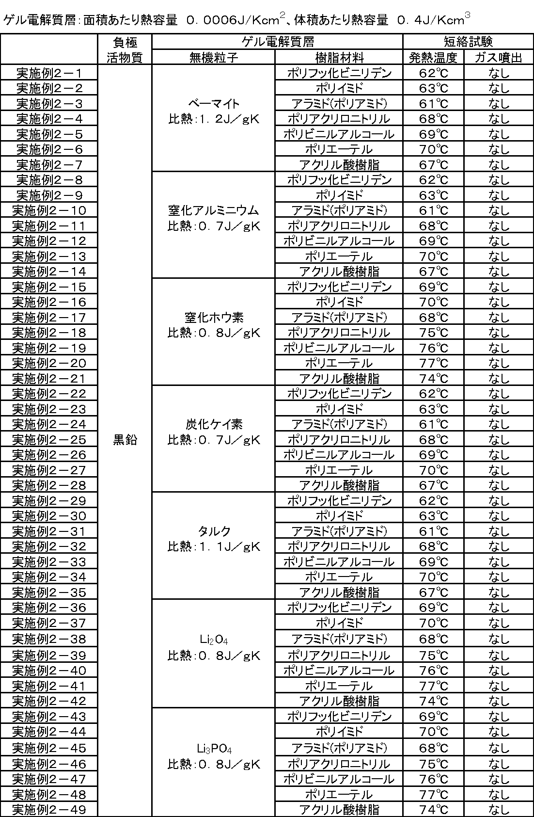


負極活物質として黒鉛の代わりに実施例1-13と同様のシリコンを用いた以外は実施例2-1~実施例2-224および比較例2-1と同様にして、実施例3-1~実施例3-224および比較例3-1のラミネートフィルム型電池をそれぞれ作製した。なお、負極活物質層を形成する負極合剤スラリーは、実施例1-13と同様の組成とした。
作製した各実施例および各比較例のラミネートフィルム型電池について、実施例1-1と同様にして短絡試験を行った。


負極活物質として黒鉛の代わりに実施例1-25と同様の炭素スズ複合材料を用いた以外は実施例2-1~実施例2-224および比較例2-1と同様にして、実施例4-1~実施例4-224および比較例4-1のラミネートフィルム型電池をそれぞれ作製した。なお、負極活物質層を形成する負極合剤スラリーは、実施例1-25と同様の組成とした。
作製した各実施例および各比較例のラミネートフィルム型電池について、実施例1-1と同様にして短絡試験を行った。

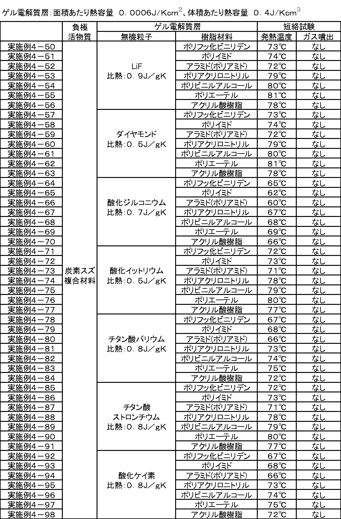


負極活物質として黒鉛の代わりに実施例1-37と同様のチタン酸リチウムを用いた以外は実施例2-1~実施例2-224および比較例2-1と同様にして、実施例5-1~実施例5-224および比較例4-1のラミネートフィルム型電池をそれぞれ作製した。なお、負極活物質層を形成する負極合剤スラリーは、実施例1-37と同様の組成とした。
作製した各実施例および各比較例のラミネートフィルム型電池について、実施例1-1と同様にして短絡試験を行った。
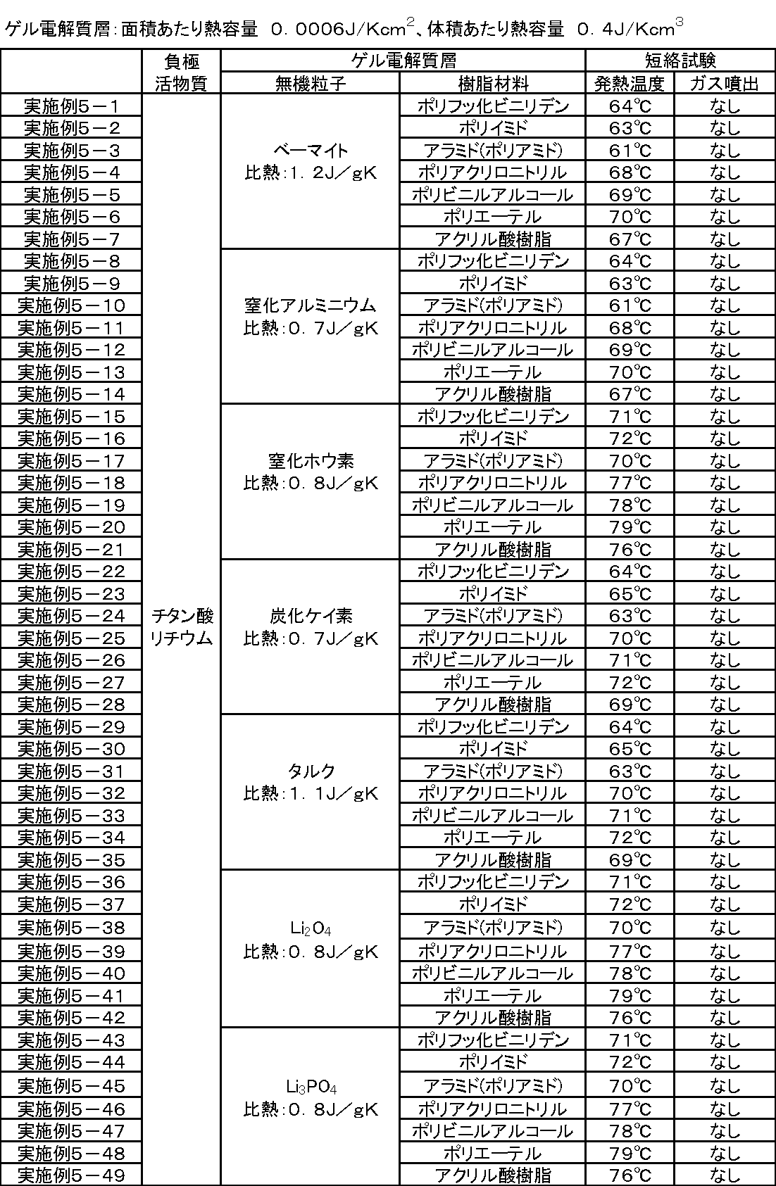
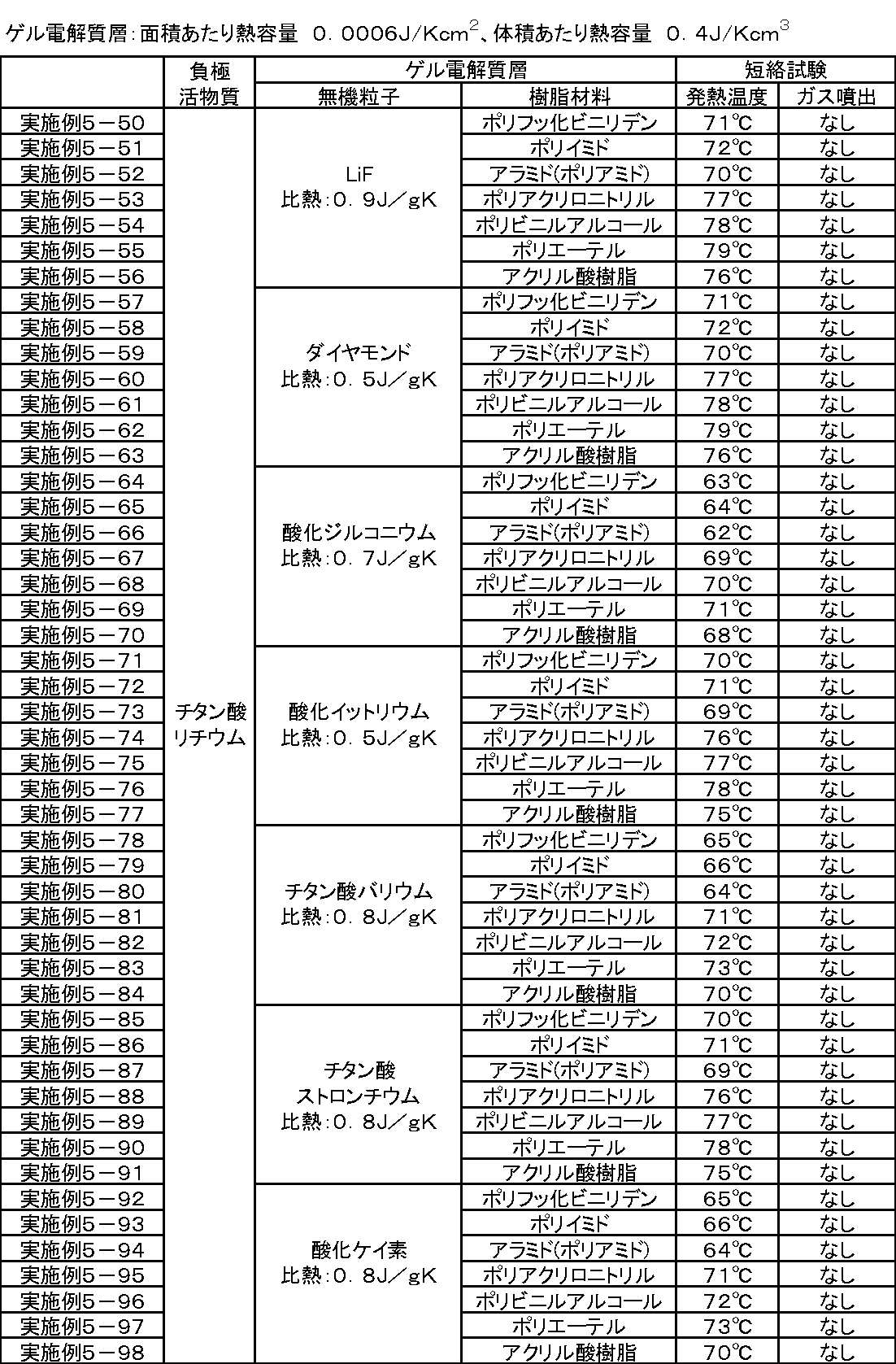


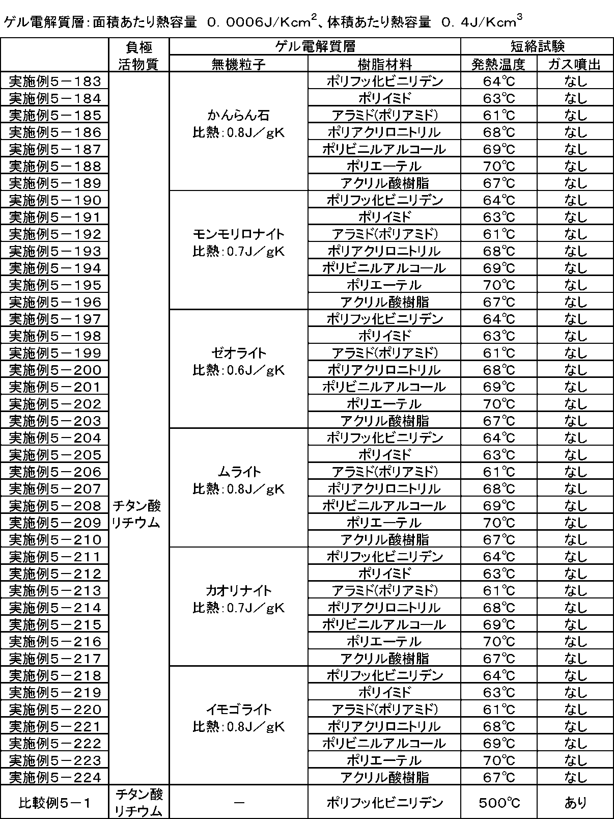
実施例1-1と同様のラミネートフィルム型電池を作製し、9μmのポリエチレン製微多孔性フィルムの両面(表6では基材両面と称する)に、片面厚さ7.5μmのゲル電解質層が形成された実施例6-1のラミネートフィルム型電池とした。すなわち、正極およびセパレータ、並びに、負極およびセパレータの間にゲル電解質層が形成されたものを実施例6-1のラミネートフィルム型電池とした。
正極の両面にのみ、実施例1-1と同様の前駆溶液を塗布し、乾燥させて可塑剤を除去することにより、厚さ9μmのポリエチレン製微多孔性フィルムの正極側面(電池作製時において正極と対向する面;表6では基材正極側面と称する)のみに、片面厚さ15μmのゲル電解質層を形成した。すなわち、正極およびセパレータの間のみにゲル電解質層を形成した。以上のこと以外は実施例6-1と同様にしてラミネートフィルム型電池を作製した。
負極の両面にのみ、実施例1-1と同様の前駆溶液を塗布し、乾燥させて可塑剤を除去することにより、厚さ9μmのポリエチレン製微多孔性フィルムの負極側面(電池作製時において負極と対向する面;表6では基材負極側面と称する)のみに、片面厚さ15μmのゲル電解質層を形成した。すなわち、正極およびセパレータの間のみにゲル電解質層を形成した。以上のこと以外は、実施例6-1と同様にしてラミネートフィルム型電池を作製した。
負極活物質としてシリコンを用い、負極合剤スラリーを実施例1-13と同様の構成とした以外は、実施例6-1~実施例6-3と同様にして実施例6-4~実施例6-6のラミネートフィルム型電池をそれぞれ作製した。
負極活物質として炭素スズ複合材料を用い、負極合剤スラリーを実施例1-25と同様の構成とした以外は、実施例6-1~実施例6-3と同様にして実施例6-7~実施例6-9のラミネートフィルム型電池をそれぞれ作製した。
負極活物質としてチタン酸リチウムを用い、負極合剤スラリーを実施例1-37と同様の構成とした以外は、実施例6-1~実施例6-3と同様にして実施例6-10~実施例6-12のラミネートフィルム型電池をそれぞれ作製した。
正極、負極、セパレータおよびゲル電解質層のそれぞれの構成が実施例6-1と同様であり、積層電極体とを軟質ラミネートフィルムで外装したラミネートフィルム型電池を作製した。すなわち、電池構成は電池外装がラミネートフィルム、電極体は積層型、負極活物質は黒鉛とした。
矩形状の正極および負極の両面に、実施例6-1と同様の前駆溶液を塗布し、乾燥させて可塑剤を除去し、正極および負極の表面にゲル電解質層を形成した。次に、矩形状の正極および負極と、セパレータとを、正極(両面にゲル電解質層が形成されたもの)、セパレータ、負極(両面にゲル電解質層が形成されたもの)、セパレータの順に積層して積層電極体を形成した。
電池構成を実施例6-13と同様のラミネートフィルム型電池とした以外は、実施例6-2~実施例6-12と同様にして実施例6-14~実施例6-24のラミネートフィルム型電池をそれぞれ作製した。
正極、負極、セパレータおよびゲル電解質層のそれぞれの構成が実施例6-1と同様であり、巻回電極体を軟質ラミネートフィルムで外装したラミネートフィルム型電池を作製した。すなわち、電池構成は電池外装がラミネートフィルム、電極体は扁平巻回型、負極活物質は黒鉛とした。また、セパレータは、厚さ9μmのポリエチレン製微多孔性フィルムとした。以下、ラミネートフィルム型電池の組み立て方法を説明する。
正極および負極の両面に、実施例6-1と同様の前駆溶液を塗布し、乾燥させて可塑剤を除去し、正極および負極の表面にゲル電解質層を形成した。次に、正極および負極と、セパレータとを、正極(ゲル電解質層が両面に形成されたもの)、セパレータ、負極(ゲル電解質層が両面に形成されたもの)、セパレータの順に積層し、長手方向に多数回、扁平形状に巻回させた後、巻き終わり部分を粘着テープで固定することにより巻回電極体を形成した。
電池構成を実施例6-25と同様のラミネートフィルム型電池とした以外は、実施例6-2~実施例6-12と同様にして実施例6-26~実施例6-36のラミネートフィルム型電池をそれぞれ作製した。
実施例1’-1と同様のラミネートフィルム型電池を作製し、9μmのポリエチレン製微多孔性フィルムの両面(表6では基材両面と称する)に、片面厚さ7.6μmのゲル電解質層が形成された実施例6’-1のラミネートフィルム型電池とした。すなわち、正極およびセパレータ、並びに、負極およびセパレータの間にゲル電解質層が形成されたものを実施例6’-1のラミネートフィルム型電池とした。
正極の両面にのみ、実施例1’-1と同様の前駆溶液を塗布し、乾燥させて可塑剤を除去することにより、厚さ9μmのポリエチレン製微多孔性フィルムの正極側面(電池作製時において正極と対向する面;表6では基材正極側面と称する)のみに、片面厚さ15.2μmのゲル電解質層を形成した。すなわち、正極およびセパレータの間のみにゲル電解質層を形成した。以上のこと以外は実施例6’-1と同様にしてラミネートフィルム型電池を作製した。
負極の両面にのみ、実施例1’-1と同様の前駆溶液を塗布し、乾燥させて可塑剤を除去することにより、厚さ9μmのポリエチレン製微多孔性フィルムの負極側面(電池作製時において負極と対向する面;表6では基材負極側面と称する)のみに、片面厚さ15.2μmのゲル電解質層を形成した。すなわち、正極およびセパレータの間のみにゲル電解質層を形成した。以上のこと以外は、実施例6’-1と同様にしてラミネートフィルム型電池を作製した。
負極活物質としてシリコンを用い、負極合剤スラリーを実施例1’-13と同様の構成とした以外は、実施例6’-1~実施例6’-3と同様にして実施例6’-4~実施例6’-6のラミネートフィルム型電池をそれぞれ作製した。
負極活物質として炭素スズ複合材料を用い、負極合剤スラリーを実施例1’-25と同様の構成とした以外は、実施例6’-1~実施例6’-3と同様にして実施例6’-7~実施例6’-9のラミネートフィルム型電池をそれぞれ作製した。
負極活物質としてチタン酸リチウムを用い、負極合剤スラリーを実施例1’-37と同様の構成とした以外は、実施例6’-1~実施例6’-3と同様にして実施例6’-10~実施例6’-12のラミネートフィルム型電池をそれぞれ作製した。
正極、負極、セパレータおよびゲル電解質層のそれぞれの構成が実施例6’-1と同様であり、積層電極体とを軟質ラミネートフィルムで外装したラミネートフィルム型電池を作製した。すなわち、電池構成は電池外装がラミネートフィルム、電極体は積層型、負極活物質は黒鉛とした。
矩形状の正極および負極の両面に、実施例6’-1と同様の前駆溶液を塗布し、乾燥させて可塑剤を除去し、正極および負極の表面にゲル電解質層を形成した。次に、矩形状の正極および負極と、セパレータとを、正極(両面にゲル電解質層が形成されたもの)、セパレータ、負極(両面にゲル電解質層が形成されたもの)、セパレータの順に積層して積層電極体を形成した。
電池構成を実施例6’-13と同様のラミネートフィルム型電池とした以外は、実施例6’-2~実施例6’-12と同様にして実施例6’-14~実施例6’-24のラミネートフィルム型電池をそれぞれ作製した。
正極、負極、セパレータおよびゲル電解質層のそれぞれの構成が実施例6’-1と同様であり、巻回電極体を軟質ラミネートフィルムで外装したラミネートフィルム型電池を作製した。すなわち、電池構成は電池外装がラミネートフィルム、電極体は扁平巻回型、負極活物質は黒鉛とした。また、セパレータは、厚さ9μmのポリエチレン製微多孔性フィルムとした。以下、ラミネートフィルム型電池の組み立て方法を説明する。
正極および負極の両面に、実施例6’-1と同様の前駆溶液を塗布し、乾燥させて可塑剤を除去し、正極および負極の表面にゲル電解質層を形成した。次に、正極および負極と、セパレータとを、正極(ゲル電解質層が両面に形成されたもの)、セパレータ、負極(ゲル電解質層が両面に形成されたもの)、セパレータの順に積層し、長手方向に多数回、扁平形状に巻回させた後、巻き終わり部分を粘着テープで固定することにより巻回電極体を形成した。
電池構成を実施例6’-25と同様のラミネートフィルム型電池とした以外は、実施例6’-2~実施例6’-12と同様にして実施例6’-26~実施例6’-36のラミネートフィルム型電池をそれぞれ作製した。
作製した各実施例および各比較例の電池について、実施例1-1と同様にして短絡試験を行った。


<実施例7-1>
実施例1-1と同様にして、吸熱体粒子として、粒子形状が球状のべーマイト(「長軸の長さ」/「短軸の長さ」=1倍)を用いたラミネートフィルム型電池を作製した。なお、粒子形状の比率(「長軸の長さ」/「短軸の長さ」)は、以下のように求めたものである。50個の粒子をランダムに選択して、選択した各無機粒子を走査型電子顕微鏡で、3次元的に観察した。これにより、各無機粒子の最長部分の長さ(長軸の長さ)と、長軸に直交する各無機粒子の最短部分の長さ(短軸の長さ(厚みまたは太さ))とから、各無機粒子の比率(「長軸の長さ」/「短軸の長さ」)を得た。そして、これらの平均値を実施例7-1の比率(「長軸の長さ」/「短軸の長さ」)とした。(以下の各実施例においても同様)
吸熱粒子として、粒子形状が板状のベーマイト(長さ:厚み=3:1、すなわち、「長軸の長さ」/「短軸の長さ」=3倍)を用いた以外は、実施例7-1と同様にしてラミネートフィルム型電池を作製した。
吸熱粒子として、粒子形状が針状のベーマイト(長さ:太さ=3:1、すなわち、「長軸の長さ」/「短軸の長さ」=3倍)を用いた以外は、実施例7-1と同様にしてラミネートフィルム型電池を作製した。
実施例7-4では、吸熱粒子として、粒子形状が球状の窒化アルミニウム(「長軸の長さ」/「短軸の長さ」=1倍)用いた。実施例7-5では、吸熱粒子として、粒子形状が板状の窒化アルミニウム(長さ:厚み=3:1、すなわち、「長軸の長さ」/「短軸の長さ」=3倍)を用いた。実施例7-6では、吸熱粒子として、粒子形状が針状の窒化アルミニウム(長さ:太さ=3:1、すなわち、「長軸の長さ」/「短軸の長さ」=3倍)を用いた。以上のこと以外は、実施例7-1と同様にしてラミネートフィルム型電池を作製した。
実施例7-7では、吸熱粒子として、粒子形状が球状の窒化ホウ素(「長軸の長さ」/「短軸の長さ」=1倍)用いた。実施例7-8では、吸熱粒子として、粒子形状が板状の窒化ホウ素(長さ:厚み=3:1、すなわち、「長軸の長さ」/「短軸の長さ」=3倍)を用いた。実施例7-9では、吸熱粒子として、粒子形状が針状の窒化ホウ素(長さ:太さ=3:1、すなわち、「長軸の長さ」/「短軸の長さ」=3倍)を用いた。以上のこと以外は、実施例7-1と同様にしてラミネートフィルム型電池を作製した。
実施例7-10では、吸熱粒子として、粒子形状が球状の炭化ケイ素(「長軸の長さ」/「短軸の長さ」=1倍)用いた。実施例7-11では、吸熱粒子として、粒子形状が板状の炭化ケイ素(長さ:厚み=3:1、すなわち、「長軸の長さ」/「短軸の長さ」=3倍)を用いた。実施例7-12では、吸熱粒子として、粒子形状が針状の炭化ケイ素(長さ:太さ=3:1、すなわち、「長軸の長さ」/「短軸の長さ」=3倍)を用いた。以上のこと以外は、実施例7-1と同様にしてラミネートフィルム型電池を作製した。
実施例7-13では、吸熱粒子として、粒子形状が球状のタルク(「長軸の長さ」/「短軸の長さ」=1倍)用いた。実施例7-14では、吸熱粒子として、粒子形状が板状のタルク(長さ:厚み=3:1、すなわち、「長軸の長さ」/「短軸の長さ」=3倍)を用いた。実施例7-15では、吸熱粒子として、粒子形状が針状のタルク(長さ:太さ=3:1、すなわち、「長軸の長さ」/「短軸の長さ」=3倍)を用いた。以上のこと以外は、実施例7-1と同様にしてラミネートフィルム型電池を作製した。
実施例7-16では、吸熱粒子として、粒子形状が球状のLi2O4(「長軸の長さ」/「短軸の長さ」=1倍)用いた。実施例7-17では、吸熱粒子として、粒子形状が板状のLi2O4(長さ:厚み=3:1、すなわち、「長軸の長さ」/「短軸の長さ」=3倍)を用いた。実施例7-18では、吸熱粒子として、粒子形状が針状のLi2O4(長さ:太さ=3:1、すなわち、「長軸の長さ」/「短軸の長さ」=3倍)を用いた。以上のこと以外は、実施例7-1と同様にしてラミネートフィルム型電池を作製した。
実施例7-19では、吸熱粒子として、粒子形状が球状のLi3PO4(「長軸の長さ」/「短軸の長さ」=1倍)用いた。実施例7-20では、吸熱粒子として、粒子形状が板状のLi3PO4(長さ:厚み=3:1、すなわち、「長軸の長さ」/「短軸の長さ」=3倍)を用いた。実施例7-21では、吸熱粒子として、粒子形状が針状のLi3PO4(長さ:太さ=3:1、すなわち、「長軸の長さ」/「短軸の長さ」=3倍)を用いた。以上のこと以外は、実施例7-1と同様にしてラミネートフィルム型電池を作製した。
実施例7-22では、吸熱粒子として、粒子形状が球状のLiF(「長軸の長さ」/「短軸の長さ」=1倍)用いた。実施例7-23では、吸熱粒子として、粒子形状が板状のLiF(長さ:厚み=3:1、すなわち、「長軸の長さ」/「短軸の長さ」=3倍)を用いた。実施例7-24では、吸熱粒子として、粒子形状が針状のLiF(長さ:太さ=3:1、すなわち、「長軸の長さ」/「短軸の長さ」=3倍)を用いた。以上のこと以外は、実施例7-1と同様にしてラミネートフィルム型電池を作製した。
実施例7-25では、吸熱粒子として、粒子形状が球状のダイヤモンド(「長軸の長さ」/「短軸の長さ」=1倍)用いた。実施例7-26では、吸熱粒子として、粒子形状が板状のダイヤモンド(長さ:厚み=3:1、すなわち、「長軸の長さ」/「短軸の長さ」=3倍)を用いた。実施例7-27では、吸熱粒子として、粒子形状が針状のダイヤモンド(長さ:太さ=3:1、すなわち、「長軸の長さ」/「短軸の長さ」=3倍)を用いた。以上のこと以外は、実施例7-1と同様にしてラミネートフィルム型電池を作製した。
実施例7-28では、吸熱粒子として、粒子形状が球状のジルコニア(「長軸の長さ」/「短軸の長さ」=1倍)用いた。実施例7-29では、吸熱粒子として、粒子形状が板状のジルコニア(長さ:厚み=3:1、すなわち、「長軸の長さ」/「短軸の長さ」=3倍)を用いた。実施例7-30では、吸熱粒子として、粒子形状が針状のジルコニア(長さ:太さ=3:1、すなわち、「長軸の長さ」/「短軸の長さ」=3倍)を用いた。以上のこと以外は、実施例7-1と同様にしてラミネートフィルム型電池を作製した。
実施例7-31では、吸熱粒子として、粒子形状が球状の酸化イットリウム(「長軸の長さ」/「短軸の長さ」=1倍)用いた。実施例7-32では、吸熱粒子として、粒子形状が板状の酸化イットリウム(長さ:厚み=3:1、すなわち、「長軸の長さ」/「短軸の長さ」=3倍)を用いた。実施例7-33では、吸熱粒子として、粒子形状が針状の酸化イットリウム(長さ:太さ=3:1、すなわち、「長軸の長さ」/「短軸の長さ」=3倍)を用いた。以上のこと以外は、実施例7-1と同様にしてラミネートフィルム型電池を作製した。
実施例7-34では、吸熱粒子として、粒子形状が球状のチタン酸バリウム(「長軸の長さ」/「短軸の長さ」=1倍)用いた。実施例7-35では、吸熱粒子として、粒子形状が板状のチタン酸バリウム(長さ:厚み=3:1、すなわち、「長軸の長さ」/「短軸の長さ」=3倍)を用いた。実施例7-36では、吸熱粒子として、粒子形状が針状のチタン酸バリウム(長さ:太さ=3:1、すなわち、「長軸の長さ」/「短軸の長さ」=3倍)を用いた。以上のこと以外は、実施例7-1と同様にしてラミネートフィルム型電池を作製した。
実施例7-37では、吸熱粒子として、粒子形状が球状のチタン酸ストロンチウム(「長軸の長さ」/「短軸の長さ」=1倍)用いた。実施例7-38では、吸熱粒子として、粒子形状が板状のチタン酸ストロンチウム(長さ:厚み=3:1、すなわち、「長軸の長さ」/「短軸の長さ」=3倍)を用いた。実施例7-39では、吸熱粒子として、粒子形状が針状のチタン酸ストロンチウム(長さ:太さ=3:1、すなわち、「長軸の長さ」/「短軸の長さ」=3倍)を用いた。以上のこと以外は、実施例7-1と同様にしてラミネートフィルム型電池を作製した。
実施例7-40では、吸熱粒子として、粒子形状が球状の酸化ケイ素(「長軸の長さ」/「短軸の長さ」=1倍)用いた。実施例7-41では、吸熱粒子として、粒子形状が板状の酸化ケイ素(長さ:厚み=3:1、すなわち、「長軸の長さ」/「短軸の長さ」=3倍)を用いた。実施例7-42では、吸熱粒子として、粒子形状が針状の酸化ケイ素(長さ:太さ=3:1、すなわち、「長軸の長さ」/「短軸の長さ」=3倍)を用いた。以上のこと以外は、実施例7-1と同様にしてラミネートフィルム型電池を作製した。
実施例7-43では、吸熱粒子として、粒子形状が球状のゼオライト(「長軸の長さ」/「短軸の長さ」=1倍)用いた。実施例7-44では、吸熱粒子として、粒子形状が板状のゼオライト(長さ:厚み=3:1、すなわち、「長軸の長さ」/「短軸の長さ」=3倍)を用いた。実施例7-45では、吸熱粒子として、粒子形状が針状のゼオライト(長さ:太さ=3:1、すなわち、「長軸の長さ」/「短軸の長さ」=3倍)を用いた。以上のこと以外は、実施例7-1と同様にしてラミネートフィルム型電池を作製した。
実施例7-46では、吸熱粒子として、粒子形状が球状の硫酸バリウム(「長軸の長さ」/「短軸の長さ」=1倍)用いた。実施例7-47では、吸熱粒子として、粒子形状が板状の硫酸バリウム(長さ:厚み=3:1、すなわち、「長軸の長さ」/「短軸の長さ」=3倍)を用いた。実施例7-48では、吸熱粒子として、粒子形状が針状の硫酸バリウム(長さ:太さ=3:1、すなわち、「長軸の長さ」/「短軸の長さ」=3倍)を用いた。以上のこと以外は、実施例7-1と同様にしてラミネートフィルム型電池を作製した。
実施例7-49では、吸熱粒子として、粒子形状が球状の酸化チタン(「長軸の長さ」/「短軸の長さ」=1倍)用いた。実施例7-50では、吸熱粒子として、粒子形状が板状の酸化チタン(長さ:厚み=3:1、すなわち、「長軸の長さ」/「短軸の長さ」=3倍)を用いた。実施例7-51では、吸熱粒子として、粒子形状が針状の酸化チタン(長さ:太さ=3:1、すなわち、「長軸の長さ」/「短軸の長さ」=3倍)を用いた。以上のこと以外は、実施例7-1と同様にしてラミネートフィルム型電池を作製した。
実施例7-52では、吸熱粒子として、粒子形状が球状の酸化マグネシウム(「長軸の長さ」/「短軸の長さ」=1倍)用いた。実施例7-53では、吸熱粒子として、粒子形状が板状の酸化マグネシウム(長さ:厚み=3:1、すなわち、「長軸の長さ」/「短軸の長さ」=3倍)を用いた。実施例7-54では、吸熱粒子として、粒子形状が針状の酸化マグネシウム(長さ:太さ=3:1、すなわち、「長軸の長さ」/「短軸の長さ」=3倍)を用いた。以上のこと以外は、実施例7-1と同様にしてラミネートフィルム型電池を作製した。
実施例7-55では、吸熱粒子として、粒子形状が球状の黒鉛(「長軸の長さ」/「短軸の長さ」=1倍)用いた。実施例7-56では、吸熱粒子として、粒子形状が板状の黒鉛(長さ:厚み=3:1、すなわち、「長軸の長さ」/「短軸の長さ」=3倍)を用いた。実施例7-57では、吸熱粒子として、粒子形状が針状の黒鉛(長さ:太さ=3:1、すなわち、「長軸の長さ」/「短軸の長さ」=3倍)を用いた。以上のこと以外は、実施例7-1と同様にしてラミネートフィルム型電池を作製した。
吸熱粒子として、粒子形状が針状のカーボンナノチューブ(長さ:太さ=3:1、すなわち、「長軸の長さ」/「短軸の長さ」=10倍)を用いた以外は、実施例7-1と同様にしてラミネートフィルム型電池を作製した。
実施例7-59では、吸熱粒子として、粒子形状が球状の水酸化アルミニウム(「長軸の長さ」/「短軸の長さ」=1倍)用いた。実施例7-60では、吸熱粒子として、粒子形状が板状の水酸化アルミニウム(長さ:厚み=3:1、すなわち、「長軸の長さ」/「短軸の長さ」=3倍)を用いた。実施例7-61では、吸熱粒子として、粒子形状が針状の水酸化アルミニウム(長さ:太さ=3:1、すなわち、「長軸の長さ」/「短軸の長さ」=3倍)を用いた。以上のこと以外は、実施例7-1と同様にしてラミネートフィルム型電池を作製した。
実施例7-62では、吸熱粒子として、粒子形状が球状の炭化ホウ素(「長軸の長さ」/「短軸の長さ」=1倍)用いた。実施例7-63では、吸熱粒子として、粒子形状が板状の炭化ホウ素(長さ:厚み=3:1、すなわち、「長軸の長さ」/「短軸の長さ」=3倍)を用いた。実施例7-64では、吸熱粒子として、粒子形状が針状の炭化ホウ素(長さ:太さ=3:1、すなわち、「長軸の長さ」/「短軸の長さ」=3倍)を用いた。以上のこと以外は、実施例7-1と同様にしてラミネートフィルム型電池を作製した。
実施例7-65では、吸熱粒子として、粒子形状が球状の窒化ケイ素(「長軸の長さ」/「短軸の長さ」=1倍)用いた。実施例7-66では、吸熱粒子として、粒子形状が板状の窒化ケイ素(長さ:厚み=3:1、すなわち、「長軸の長さ」/「短軸の長さ」=3倍)を用いた。実施例7-67では、吸熱粒子として、粒子形状が針状の窒化ケイ素(長さ:太さ=3:1、すなわち、「長軸の長さ」/「短軸の長さ」=3倍)を用いた。以上のこと以外は、実施例7-1と同様にしてラミネートフィルム型電池を作製した。
実施例7-68では、吸熱粒子として、粒子形状が球状の窒化チタン(「長軸の長さ」/「短軸の長さ」=1倍)用いた。実施例7-69では、吸熱粒子として、粒子形状が板状の窒化チタン(長さ:厚み=3:1、すなわち、「長軸の長さ」/「短軸の長さ」=3倍)を用いた。実施例7-70では、吸熱粒子として、粒子形状が針状の窒化チタン(長さ:太さ=3:1、すなわち、「長軸の長さ」/「短軸の長さ」=3倍)を用いた。以上のこと以外は、実施例7-1と同様にしてラミネートフィルム型電池を作製した。
実施例7-71では、吸熱粒子として、粒子形状が球状の酸化亜鉛(「長軸の長さ」/「短軸の長さ」=1倍)用いた。実施例7-72では、吸熱粒子として、粒子形状が板状の酸化亜鉛(長さ:厚み=3:1、すなわち、「長軸の長さ」/「短軸の長さ」=3倍)を用いた。実施例7-73では、吸熱粒子として、粒子形状が針状の酸化亜鉛(長さ:太さ=3:1、すなわち、「長軸の長さ」/「短軸の長さ」=3倍)を用いた。以上のこと以外は、実施例7-1と同様にしてラミネートフィルム型電池を作製した。
実施例7-74では、吸熱粒子として、粒子形状が球状のアルミナ(「長軸の長さ」/「短軸の長さ」=1倍)用いた。実施例7-75では、吸熱粒子として、粒子形状が板状のアルミナ(長さ:厚み=3:1、すなわち、「長軸の長さ」/「短軸の長さ」=3倍)を用いた。実施例7-76では、吸熱粒子として、粒子形状が針状のアルミナ(長さ:太さ=3:1、すなわち、「長軸の長さ」/「短軸の長さ」=3倍)を用いた。以上のこと以外は、実施例7-1と同様にしてラミネートフィルム型電池を作製した。
実施例7-77では、吸熱粒子として、粒子形状が球状のかんらん石(「長軸の長さ」/「短軸の長さ」=1倍)用いた。実施例7-78では、吸熱粒子として、粒子形状が板状のかんらん石(長さ:厚み=3:1、すなわち、「長軸の長さ」/「短軸の長さ」=3倍)を用いた。実施例7-79では、吸熱粒子として、粒子形状が針状のかんらん石(長さ:太さ=3:1、すなわち、「長軸の長さ」/「短軸の長さ」=3倍)を用いた。以上のこと以外は、実施例7-1と同様にしてラミネートフィルム型電池を作製した。
実施例7-80では、吸熱粒子として、粒子形状が球状のモンモリロナイト(「長軸の長さ」/「短軸の長さ」=1倍)用いた。実施例7-81では、吸熱粒子として、粒子形状が板状のモンモリロナイト(長さ:厚み=3:1、すなわち、「長軸の長さ」/「短軸の長さ」=3倍)を用いた。実施例7-82では、吸熱粒子として、粒子形状が針状のモンモリロナイト(長さ:太さ=3:1、すなわち、「長軸の長さ」/「短軸の長さ」=3倍)を用いた。以上のこと以外は、実施例7-1と同様にしてラミネートフィルム型電池を作製した。
実施例7-83では、吸熱粒子として、粒子形状が球状のゼオライト(「長軸の長さ」/「短軸の長さ」=1倍)用いた。実施例7-84では、吸熱粒子として、粒子形状が板状のゼオライト(長さ:厚み=3:1、すなわち、「長軸の長さ」/「短軸の長さ」=3倍)を用いた。実施例7-85では、吸熱粒子として、粒子形状が針状のゼオライト(長さ:太さ=3:1、すなわち、「長軸の長さ」/「短軸の長さ」=3倍)を用いた。以上のこと以外は、実施例7-1と同様にしてラミネートフィルム型電池を作製した。
実施例7-86では、吸熱粒子として、粒子形状が球状のムライト(「長軸の長さ」/「短軸の長さ」=1倍)用いた。実施例7-87では、吸熱粒子として、粒子形状が板状のムライト(長さ:厚み=3:1、すなわち、「長軸の長さ」/「短軸の長さ」=3倍)を用いた。実施例7-88では、吸熱粒子として、粒子形状が針状のムライト(長さ:太さ=3:1、すなわち、「長軸の長さ」/「短軸の長さ」=3倍)を用いた。以上のこと以外は、実施例7-1と同様にしてラミネートフィルム型電池を作製した。
実施例7-89では、吸熱粒子として、粒子形状が球状のカオリナイト(「長軸の長さ」/「短軸の長さ」=1倍)用いた。実施例7-90では、吸熱粒子として、粒子形状が板状のカオリナイト(長さ:厚み=3:1、すなわち、「長軸の長さ」/「短軸の長さ」=3倍)を用いた。実施例7-91では、吸熱粒子として、粒子形状が針状のカオリナイト(長さ:太さ=3:1、すなわち、「長軸の長さ」/「短軸の長さ」=3倍)を用いた。以上のこと以外は、実施例7-1と同様にしてラミネートフィルム型電池を作製した。
実施例7-92では、吸熱粒子として、粒子形状が球状のイモゴライト(「長軸の長さ」/「短軸の長さ」=1倍)用いた。実施例7-93では、吸熱粒子として、粒子形状が板状のイモゴライト(長さ:厚み=3:1、すなわち、「長軸の長さ」/「短軸の長さ」=3倍)を用いた。実施例7-94では、吸熱粒子として、粒子形状が針状のイモゴライト(長さ:太さ=3:1、すなわち、「長軸の長さ」/「短軸の長さ」=3倍)を用いた。以上のこと以外は、実施例7-1と同様にしてラミネートフィルム型電池を作製した。
作製した各実施例および各比較例の電池について、実施例1-1と同様にして短絡試験を行った。


以上、本技術を各実施の形態および実施例によって説明したが、本技術はこれらに限定されるものではなく、本技術の要旨の範囲内で種々の変形が可能である。
正極と、
負極と、
上記正極および負極の間に、粒子と電解液と該電解液を保持する樹脂材料とを含むゲル状電解質、または粒子を含む固体電解質からなる電解質層と
を備え、
上記電解質層の単位面積あたりの熱容量が0.0001J/Kcm2以上であり、かつ単位体積あたりの熱容量が3.0J/Kcm3以下である電池。
[2]
上記正極および上記負極の間に設けられたセパレータをさらに備え、
上記電解質層は、上記正極および上記セパレータの間、並びに、上記負極および上記セパレータの間の少なくとも一方にある[1]に記載の電池。
[3]
上記粒子が、上記電解質層中に分散して存在する
[1]~[2]の何れかに記載の電池。
[4]
上記粒子の比熱が、0.5J/gK以上である
[1]~[3]の何れかに記載の電池。
[5]
上記粒子が、アルミナ、ベーマイト、酸化イットリウム、酸化チタン、酸化マグネシウム、酸化ジルコニウム、酸化ケイ素、酸化亜鉛、窒化アルミニウム、窒化ホウ素、窒化ケイ素、窒化チタン、炭化ケイ素、炭化ホウ素、チタン酸バリウム、チタン酸ストロンチウム、硫酸バリウム、ケイ酸塩、Li2O4、Li3PO4、LiF、水酸化アルミニウム、黒鉛、カーボンナノチューブおよびダイヤモンドの中から選ばれた少なくとも1つを含有する
[1]~[4]の何れかに記載の電池。
[6]
上記ケイ酸塩は、ネソケイ酸塩鉱物、ソロケイ酸塩鉱物、サイクロケイ酸塩鉱物、イノケイ酸塩鉱物、フィロケイ酸塩鉱物、テクトケイ酸塩鉱物、アスベスト類、セピオライトおよびイモゴライトの中から選ばれた少なくとも1つである[5]に記載の電池。
[7]
上記ネソケイ酸塩鉱物は、かんらん石およびムライトの中から選ばれた少なくとも1つであり、
上記フィロケイ酸塩鉱物は、タルク、モンモリロナイトおよびカオリナイトの中から選ばれた少なくとも1つであり、
上記テクトケイ酸塩鉱物は、ゼオライトである[6]に記載の電池。
[8]
上記粒子の形状が、異方性を有する形状である
[1]~[7]の何れかに記載の電池。
[9]
上記粒子の最長部分の長さと、該最長部分に直交する方向における上記粒子の最短部分の長さとの比率(「上記最長部分の長さ」/{上記最短部分の長さ})が、3倍以上である[8]に記載の電池。
[10]
上記樹脂材料の融点およびガラス転移温度の少なくとも一方が、180℃以上である
[1]~[9]の何れかに記載の電池。
[11]
上記樹脂材料がポリフッ化ビニリデンである
[10]に記載の電池。
[12]
上記負極に含まれる負極活物質が、金属元素および半金属元素のうちの少なくとも1種を構成元素として含む材料からなる
[1]~[11]の何れかに記載の電池。
[13]
粒子と電解液と該電解液を保持する樹脂材料とを含むゲル状電解質、または粒子を含む固体電解質からなり、
単位面積あたりの熱容量が単位面積あたりの熱容量が0.0001J/Kcm2以上であり、かつ単位体積あたりの熱容量が3.0J/Kcm3以下である電解質層。
[14]
[1]~[11]の何れかに記載の電池と、
上記電池を制御する制御部と、
上記電池を内包する外装を有する
電池パック。
[15]
[1]~[11]の何れかに記載の電池を有し、
上記電池から電力の供給を受ける
電子機器。
[16]
[1]~[11]の何れかに記載の電池と、
上記電池から電力の供給を受けて車両の駆動力に変換する変換装置と、
上記電池に関する情報に基づいて車両制御に関する情報処理を行う制御装置とを有する
電動車両。
[17]
[1]~[11]の何れかに記載の電池を有し、
上記電池に接続される電子機器に電力を供給する蓄電装置。
[18]
他の機器とネットワークを介して信号を送受信する電力情報制御装置を備え
上記電力情報制御装置が受信した情報に基づき、上記電池の充放電制御を行う
[17]に記載の蓄電装置。
[19]
[1]~[11]の何れかに記載の電池から電力の供給を受け、または、発電装置もしくは電力網から上記電池に電力が供給される
電力システム。
Claims (19)
- 正極と、
負極と、
上記正極および上記負極の間に、粒子と電解液と該電解液を保持する樹脂材料とを含むゲル状電解質、または粒子を含む固体電解質からなる電解質層と
を備え、
上記電解質層の単位面積あたりの熱容量が0.0001J/Kcm2以上であり、かつ単位体積あたりの熱容量が3.0J/Kcm3以下である電池。 - 上記正極および上記負極の間に設けられたセパレータをさらに備え、
上記電解質層は、上記正極および上記セパレータの間、並びに、上記負極および上記セパレータの間の少なくとも一方にある請求項1に記載の電池。 - 上記粒子が、上記電解質層中に分散して存在する
請求項1に記載の電池。 - 上記粒子の比熱が、0.5J/gK以上である
請求項1に記載の電池。 - 上記粒子が、アルミナ、ベーマイト、酸化イットリウム、酸化チタン、酸化マグネシウム、酸化ジルコニウム、酸化ケイ素、酸化亜鉛、窒化アルミニウム、窒化ホウ素、窒化ケイ素、窒化チタン、炭化ケイ素、炭化ホウ素、チタン酸バリウム、チタン酸ストロンチウム、硫酸バリウム、ケイ酸塩、Li2O4、Li3PO4、LiF、水酸化アルミニウム、黒鉛、カーボンナノチューブおよびダイヤモンドの中から選ばれた少なくとも1つを含有する
請求項1に記載の電池。 - 上記ケイ酸塩は、ネソケイ酸塩鉱物、ソロケイ酸塩鉱物、サイクロケイ酸塩鉱物、イノケイ酸塩鉱物、フィロケイ酸塩鉱物、テクトケイ酸塩鉱物、アスベスト類、セピオライトおよびイモゴライトの中から選ばれた少なくとも1つである請求項5に記載の電池。
- 上記ネソケイ酸塩鉱物は、かんらん石およびムライトの中から選ばれた少なくとも1つであり、
上記フィロケイ酸塩鉱物は、タルク、モンモリロナイトおよびカオリナイトの中から選ばれた少なくとも1つであり、
上記テクトケイ酸塩鉱物は、ゼオライトである請求項6に記載の電池。 - 上記粒子の形状が、異方性を有する形状である
請求項1に記載の電池。 - 上記粒子の最長部分の長さと、該最長部分に直交する方向における上記粒子の最短部分の長さとの比率(「上記最長部分の長さ」/{上記最短部分の長さ})が、3倍以上である請求項8に記載の電池。
- 上記樹脂材料の融点およびガラス転移温度の少なくとも一方が、180℃以上である
請求項1に記載の電池。 - 上記樹脂材料がポリフッ化ビニリデンである
請求項10に記載の電池。 - 上記負極に含まれる負極活物質が、金属元素および半金属元素のうちの少なくとも1種を構成元素として含む材料からなる
請求項1に記載の電池。 - 粒子と電解液と該電解液を保持する樹脂材料とを含むゲル状電解質、または粒子を含む固体電解質からなり、
単位面積あたりの熱容量が0.0001J/Kcm2以上であり、かつ単位体積あたりの熱容量が3.0J/Kcm3以下である電解質層。 - 請求項1に記載の電池と、
上記電池を制御する制御部と、
上記電池を内包する外装を有する
電池パック。 - 請求項1に記載の電池を有し、
上記電池から電力の供給を受ける
電子機器。 - 請求項1に記載の電池と、
上記電池から電力の供給を受けて車両の駆動力に変換する変換装置と、
上記電池に関する情報に基づいて車両制御に関する情報処理を行う制御装置とを有する
電動車両。 - 請求項1に記載の電池を有し、
上記電池に接続される電子機器に電力を供給する蓄電装置。 - 他の機器とネットワークを介して信号を送受信する電力情報制御装置を備え
上記電力情報制御装置が受信した情報に基づき、上記電池の充放電制御を行う
請求項17に記載の蓄電装置。 - 請求項1に記載の電池から電力の供給を受け、または、発電装置もしくは電力網から上記電池に電力が供給される
電力システム。
Priority Applications (4)
| Application Number | Priority Date | Filing Date | Title |
|---|---|---|---|
| EP14769877.3A EP2978060B1 (en) | 2013-03-19 | 2014-02-21 | Battery, electrolyte layer, battery pack, electronic apparatus, electric vehicle, power storage device, and power system |
| KR1020157024004A KR102127541B1 (ko) | 2013-03-19 | 2014-02-21 | 전지, 전해질층, 전지 팩, 전자 기기, 전동 차량, 축전 장치 및 전력 시스템 |
| CN201480014519.3A CN105051963B (zh) | 2013-03-19 | 2014-02-21 | 电池、电解质层、电池组、电子设备、电动车辆、蓄电装置以及电力系统 |
| US14/777,346 US10084201B2 (en) | 2013-03-19 | 2014-02-21 | Battery, electrolyte layer, battery pack, electronic apparatus, electric vehicle, power storage device, and electric power system |
Applications Claiming Priority (4)
| Application Number | Priority Date | Filing Date | Title |
|---|---|---|---|
| JP2013-057330 | 2013-03-19 | ||
| JP2013057330 | 2013-03-19 | ||
| JP2013232295A JP6303412B2 (ja) | 2013-03-19 | 2013-11-08 | 電池、電解質層、電池パック、電子機器、電動車両、蓄電装置および電力システム |
| JP2013-232295 | 2013-11-08 |
Publications (1)
| Publication Number | Publication Date |
|---|---|
| WO2014147955A1 true WO2014147955A1 (ja) | 2014-09-25 |
Family
ID=51579658
Family Applications (1)
| Application Number | Title | Priority Date | Filing Date |
|---|---|---|---|
| PCT/JP2014/000899 Ceased WO2014147955A1 (ja) | 2013-03-19 | 2014-02-21 | 電池、電解質層、電池パック、電子機器、電動車両、蓄電装置および電力システム |
Country Status (6)
| Country | Link |
|---|---|
| US (1) | US10084201B2 (ja) |
| EP (1) | EP2978060B1 (ja) |
| JP (1) | JP6303412B2 (ja) |
| KR (1) | KR102127541B1 (ja) |
| CN (1) | CN105051963B (ja) |
| WO (1) | WO2014147955A1 (ja) |
Cited By (6)
| Publication number | Priority date | Publication date | Assignee | Title |
|---|---|---|---|---|
| CN104882580A (zh) * | 2015-04-09 | 2015-09-02 | 江苏华东锂电技术研究院有限公司 | 复合隔膜及其制备方法以及锂离子电池 |
| US20170194663A1 (en) * | 2016-01-04 | 2017-07-06 | Aruna Zhamu | Solid state electrolyte for lithium secondary battery |
| CN107078339A (zh) * | 2014-10-21 | 2017-08-18 | 日本电气株式会社 | 二次电池及其制造方法 |
| WO2017154449A1 (ja) * | 2016-03-10 | 2017-09-14 | 株式会社クレハ | ゲル状電解質およびその調製方法 |
| US10566657B2 (en) | 2015-03-11 | 2020-02-18 | Murata Manufacturing Co., Ltd. | Electrolyte, battery, battery pack, electronic apparatus, electric vehicle, power storage apparatus, and power system |
| US10680287B2 (en) | 2016-12-12 | 2020-06-09 | Global Graphene Group, Inc. | Hybrid solid state electrolyte for lithium sulfur secondary battery |
Families Citing this family (37)
| Publication number | Priority date | Publication date | Assignee | Title |
|---|---|---|---|---|
| US10084168B2 (en) * | 2012-10-09 | 2018-09-25 | Johnson Battery Technologies, Inc. | Solid-state battery separators and methods of fabrication |
| US9755235B2 (en) | 2014-07-17 | 2017-09-05 | Ada Technologies, Inc. | Extreme long life, high energy density batteries and method of making and using the same |
| CN104466097B (zh) * | 2014-12-16 | 2017-10-10 | 东莞新能源科技有限公司 | 一种电极片及含有该电极片的锂离子电池 |
| CN105514326B (zh) * | 2015-01-16 | 2018-02-13 | 万向一二三股份公司 | 一种复合隔膜以及含有该复合隔膜的动力钛酸锂电池 |
| JP2016219134A (ja) * | 2015-05-15 | 2016-12-22 | 旭化成株式会社 | 固体電解質 |
| WO2017023797A1 (en) | 2015-07-31 | 2017-02-09 | Ada Technologies, Inc. | High energy and power electrochemical device and method of making and using same |
| JP6829943B2 (ja) * | 2016-03-10 | 2021-02-17 | 株式会社クレハ | ゲル状電解質およびその調製方法 |
| US10873106B2 (en) | 2016-03-16 | 2020-12-22 | University Of Utah Research Foundation | Composite solid electrolytes for lithium batteries |
| US10650621B1 (en) | 2016-09-13 | 2020-05-12 | Iocurrents, Inc. | Interfacing with a vehicular controller area network |
| US20190027724A1 (en) * | 2016-12-06 | 2019-01-24 | Ada Technologies, Inc. | Electrochemical Energy Storage Devices and Methods of Making and Using the Same |
| TWI628827B (zh) * | 2016-12-30 | 2018-07-01 | 財團法人工業技術研究院 | 膠態電解質及其應用 |
| JP6729410B2 (ja) * | 2017-01-17 | 2020-07-22 | トヨタ自動車株式会社 | 全固体電池 |
| US11024846B2 (en) | 2017-03-23 | 2021-06-01 | Ada Technologies, Inc. | High energy/power density, long cycle life, safe lithium-ion battery capable of long-term deep discharge/storage near zero volt and method of making and using the same |
| DE112018001902T5 (de) * | 2017-04-05 | 2019-12-19 | Gs Yuasa International Ltd. | Energiespeicherapparatur und steuerverfahren für energiespeichervorrichtungen |
| JP6875522B2 (ja) * | 2017-06-15 | 2021-05-26 | 株式会社日立製作所 | 半固体電解質、電極、半固体電解質層付き電極、および二次電池 |
| WO2019027925A1 (en) * | 2017-07-31 | 2019-02-07 | Pellion Technologies | ELECTROCHEMICAL CELL WITH GETTER AND METHOD OF FORMING THE SAME |
| US11437664B2 (en) * | 2017-09-22 | 2022-09-06 | Panasonic Intellectual Property Management Co., Ltd. | Battery module |
| KR102278388B1 (ko) * | 2017-09-28 | 2021-07-19 | 가부시키가이샤 히타치세이사쿠쇼 | 반이차 전지 및 이차 전지 |
| CN107785621A (zh) * | 2017-09-29 | 2018-03-09 | 安徽艾克瑞德科技有限公司 | 一种内化成胶体电解液及其配制方法 |
| CN112020789A (zh) * | 2018-04-27 | 2020-12-01 | 株式会社村田制作所 | 电池、电池包、电子设备、电动车辆及蓄电系统 |
| US11043705B1 (en) * | 2018-05-25 | 2021-06-22 | The United States Government Of America As Represented By The Secretary Of The Navy | Cell having implanted electronic circuit |
| JP2019212576A (ja) * | 2018-06-08 | 2019-12-12 | 株式会社日立製作所 | 半固体電解質層及び二次電池 |
| CN108808077B (zh) * | 2018-07-10 | 2021-01-12 | 北京化工大学 | 梯度钛酸钡含量的多功能凝胶聚合物电解质的制备方法 |
| US11426818B2 (en) | 2018-08-10 | 2022-08-30 | The Research Foundation for the State University | Additive manufacturing processes and additively manufactured products |
| US11329322B2 (en) * | 2018-10-03 | 2022-05-10 | Toyota Jidosha Kabushiki Kaisha | Battery module |
| US12057561B1 (en) | 2019-07-12 | 2024-08-06 | Ampcera Inc. | Systems and methods for induction heating of electrolytes |
| US11689839B2 (en) * | 2019-07-31 | 2023-06-27 | Advanced Semiconductor Engineering, Inc. | Semiconductor device package and acoustic device including the same |
| CN112531156B (zh) | 2019-09-19 | 2024-07-09 | 株式会社东芝 | 电极组、非水电解质二次电池、电池包及车辆 |
| US12272809B1 (en) | 2019-11-16 | 2025-04-08 | Ampcera Inc. | Battery cell, battery module, battery pack, electric vehicle, and method of heating |
| EP4084145A4 (en) * | 2019-12-26 | 2023-06-28 | Panasonic Holdings Corporation | Lithium ion battery |
| US11936028B1 (en) | 2020-07-13 | 2024-03-19 | Ampcera Inc. | Systems and methods for heating electrochemical systems |
| US12057554B2 (en) * | 2020-07-24 | 2024-08-06 | Roshdy G. Barsoum | Battery with ceramic particles |
| CN111816918B (zh) * | 2020-08-18 | 2022-02-01 | 中南大学 | 锂金属电池复合凝胶聚合物电解质及其制备和应用 |
| WO2023086659A2 (en) * | 2021-11-15 | 2023-05-19 | Qiao Qiao | Silicon nitride stabilized interface between lithium metal and solid electrolyte for high performance lithium metal batteries |
| CN114649587B (zh) * | 2022-03-15 | 2024-11-22 | 北京航空航天大学 | 一种基于氮化硼纳米片的准固态电解质及其制备方法和应用 |
| CN119050459A (zh) * | 2023-05-29 | 2024-11-29 | 宁德时代新能源科技股份有限公司 | 凝胶聚合物电解质、电池和用电装置 |
| CN119297398B (zh) * | 2024-09-11 | 2025-11-07 | 惠州锂威新能源科技有限公司 | 一种锂离子电池及其应用 |
Citations (14)
| Publication number | Priority date | Publication date | Assignee | Title |
|---|---|---|---|---|
| JPH05303980A (ja) * | 1992-04-24 | 1993-11-16 | Yuasa Corp | イオン伝導性高分子化合物及びその製造方法 |
| JPH08255615A (ja) * | 1995-03-20 | 1996-10-01 | Nippondenso Co Ltd | 非水電解質電池 |
| JPH10334731A (ja) * | 1997-04-04 | 1998-12-18 | Showa Denko Kk | 複合電解質及びその用途 |
| JPH11233146A (ja) * | 1998-02-19 | 1999-08-27 | Matsushita Electric Ind Co Ltd | 有機電解質電池 |
| JP2003257489A (ja) * | 2002-02-28 | 2003-09-12 | Mitsubishi Materials Corp | ゲル状ポリマー電解質及びその製造方法並びに該電解質を用いたリチウムポリマー電池 |
| JP2005174686A (ja) * | 2003-12-10 | 2005-06-30 | Nissan Motor Co Ltd | リチウムイオン電池 |
| JP2005353582A (ja) | 2004-05-11 | 2005-12-22 | Sony Corp | 電解液および電池 |
| JP2011159488A (ja) | 2010-02-01 | 2011-08-18 | Sony Corp | 非水電解質組成物および非水電解質二次電池 |
| JP2011181353A (ja) * | 2010-03-02 | 2011-09-15 | Sony Corp | 非水電解質組成物、および非水電解質電池 |
| JP2011210433A (ja) * | 2010-03-29 | 2011-10-20 | Sony Corp | 非水電解質組成物および非水電解質電池 |
| JP2012074367A (ja) * | 2010-08-30 | 2012-04-12 | Sony Corp | 非水電解質電池および非水電解質電池の製造方法、並びに絶縁材および絶縁材の製造方法、並びに電池パック、電子機器、電動車両、蓄電装置および電力システム |
| JP2012138335A (ja) * | 2010-12-09 | 2012-07-19 | Sony Corp | 非水電解質二次電池および非水電解質、並びに電池パック、電子機器、電動車両、蓄電装置および電力システム |
| JP2013054973A (ja) * | 2011-09-05 | 2013-03-21 | Sony Corp | セパレータ、非水電解質電池、電池パック、電子機器、電動車両、蓄電装置および電力システム |
| JP2013137984A (ja) * | 2011-09-05 | 2013-07-11 | Sony Corp | セパレータおよび非水電解質電池 |
Family Cites Families (14)
| Publication number | Priority date | Publication date | Assignee | Title |
|---|---|---|---|---|
| US3622398A (en) * | 1968-10-04 | 1971-11-23 | Matsushita Electric Industrial Co Ltd | Sealed type storage battery |
| DK147217C (da) * | 1978-07-12 | 1984-11-19 | Peter Olaf Henk | Elektrisk akkumulator med blysaltholdig elektrolyt |
| DK147218C (da) * | 1980-01-10 | 1984-11-05 | Peter Olaf Henk | Elektrisk akkumulator med blysaltholdig elektrolyt |
| US5202196A (en) * | 1990-04-26 | 1993-04-13 | Lianxiang Wang | High capacity colloidal storage battery, a collodial electrolyte used in it, and the processes for producing them |
| JP3143273B2 (ja) * | 1993-06-30 | 2001-03-07 | 松下電器産業株式会社 | 電解質シート |
| JP3879140B2 (ja) * | 1996-05-15 | 2007-02-07 | 松下電器産業株式会社 | リチウム・ポリマ二次電池 |
| DE69825797T2 (de) | 1997-03-13 | 2005-09-01 | Matsushita Electric Industrial Co., Ltd., Kadoma | Lithium-Ionen-Batterie |
| KR100441611B1 (ko) | 1998-12-22 | 2004-09-18 | 주식회사 파인셀 | 흡수제를 이용한 고분자 전해질 및 그의 제조방법 |
| EP1290749A4 (en) | 2000-05-24 | 2004-09-22 | Finecell Co Ltd | MICROPOROUS FIXED ELECTROLYTES AND METHOD FOR THE PRODUCTION THEREOF |
| KR20030007659A (ko) * | 2002-11-20 | 2003-01-23 | 주식회사 파인셀 | 미세 다공성 고체 무기전해질 및 그의 제조방법 |
| US7077983B2 (en) * | 2002-12-31 | 2006-07-18 | University Of Chicago | Polymer nanocomposites for lithium battery applications |
| JP4741526B2 (ja) * | 2006-08-14 | 2011-08-03 | ソニー株式会社 | 非水電解質二次電池 |
| JP2011060558A (ja) * | 2009-09-09 | 2011-03-24 | Sony Corp | 非水電解質電池 |
| US20140205909A1 (en) * | 2011-08-23 | 2014-07-24 | Nippon Shokubai Co., Ltd. | Negative electrode mixture or gel electrolyte, and battery using said negative electrode mixture or said gel electrolyte |
-
2013
- 2013-11-08 JP JP2013232295A patent/JP6303412B2/ja active Active
-
2014
- 2014-02-21 WO PCT/JP2014/000899 patent/WO2014147955A1/ja not_active Ceased
- 2014-02-21 EP EP14769877.3A patent/EP2978060B1/en active Active
- 2014-02-21 KR KR1020157024004A patent/KR102127541B1/ko active Active
- 2014-02-21 US US14/777,346 patent/US10084201B2/en active Active
- 2014-02-21 CN CN201480014519.3A patent/CN105051963B/zh active Active
Patent Citations (14)
| Publication number | Priority date | Publication date | Assignee | Title |
|---|---|---|---|---|
| JPH05303980A (ja) * | 1992-04-24 | 1993-11-16 | Yuasa Corp | イオン伝導性高分子化合物及びその製造方法 |
| JPH08255615A (ja) * | 1995-03-20 | 1996-10-01 | Nippondenso Co Ltd | 非水電解質電池 |
| JPH10334731A (ja) * | 1997-04-04 | 1998-12-18 | Showa Denko Kk | 複合電解質及びその用途 |
| JPH11233146A (ja) * | 1998-02-19 | 1999-08-27 | Matsushita Electric Ind Co Ltd | 有機電解質電池 |
| JP2003257489A (ja) * | 2002-02-28 | 2003-09-12 | Mitsubishi Materials Corp | ゲル状ポリマー電解質及びその製造方法並びに該電解質を用いたリチウムポリマー電池 |
| JP2005174686A (ja) * | 2003-12-10 | 2005-06-30 | Nissan Motor Co Ltd | リチウムイオン電池 |
| JP2005353582A (ja) | 2004-05-11 | 2005-12-22 | Sony Corp | 電解液および電池 |
| JP2011159488A (ja) | 2010-02-01 | 2011-08-18 | Sony Corp | 非水電解質組成物および非水電解質二次電池 |
| JP2011181353A (ja) * | 2010-03-02 | 2011-09-15 | Sony Corp | 非水電解質組成物、および非水電解質電池 |
| JP2011210433A (ja) * | 2010-03-29 | 2011-10-20 | Sony Corp | 非水電解質組成物および非水電解質電池 |
| JP2012074367A (ja) * | 2010-08-30 | 2012-04-12 | Sony Corp | 非水電解質電池および非水電解質電池の製造方法、並びに絶縁材および絶縁材の製造方法、並びに電池パック、電子機器、電動車両、蓄電装置および電力システム |
| JP2012138335A (ja) * | 2010-12-09 | 2012-07-19 | Sony Corp | 非水電解質二次電池および非水電解質、並びに電池パック、電子機器、電動車両、蓄電装置および電力システム |
| JP2013054973A (ja) * | 2011-09-05 | 2013-03-21 | Sony Corp | セパレータ、非水電解質電池、電池パック、電子機器、電動車両、蓄電装置および電力システム |
| JP2013137984A (ja) * | 2011-09-05 | 2013-07-11 | Sony Corp | セパレータおよび非水電解質電池 |
Non-Patent Citations (1)
| Title |
|---|
| See also references of EP2978060A4 |
Cited By (10)
| Publication number | Priority date | Publication date | Assignee | Title |
|---|---|---|---|---|
| CN107078339A (zh) * | 2014-10-21 | 2017-08-18 | 日本电气株式会社 | 二次电池及其制造方法 |
| EP3211707A4 (en) * | 2014-10-21 | 2018-03-07 | Nec Corporation | Secondary battery and production method therefor |
| CN107078339B (zh) * | 2014-10-21 | 2019-12-17 | 日本电气株式会社 | 二次电池及其制造方法 |
| US10566657B2 (en) | 2015-03-11 | 2020-02-18 | Murata Manufacturing Co., Ltd. | Electrolyte, battery, battery pack, electronic apparatus, electric vehicle, power storage apparatus, and power system |
| CN104882580A (zh) * | 2015-04-09 | 2015-09-02 | 江苏华东锂电技术研究院有限公司 | 复合隔膜及其制备方法以及锂离子电池 |
| US20170194663A1 (en) * | 2016-01-04 | 2017-07-06 | Aruna Zhamu | Solid state electrolyte for lithium secondary battery |
| US10497968B2 (en) * | 2016-01-04 | 2019-12-03 | Global Graphene Group, Inc. | Solid state electrolyte for lithium secondary battery |
| US11374254B2 (en) | 2016-01-04 | 2022-06-28 | Global Graphene Group, Inc. | Solid state electrolyte for lithium secondary battery |
| WO2017154449A1 (ja) * | 2016-03-10 | 2017-09-14 | 株式会社クレハ | ゲル状電解質およびその調製方法 |
| US10680287B2 (en) | 2016-12-12 | 2020-06-09 | Global Graphene Group, Inc. | Hybrid solid state electrolyte for lithium sulfur secondary battery |
Also Published As
| Publication number | Publication date |
|---|---|
| US20160043429A1 (en) | 2016-02-11 |
| CN105051963A (zh) | 2015-11-11 |
| EP2978060A1 (en) | 2016-01-27 |
| KR20150132128A (ko) | 2015-11-25 |
| EP2978060B1 (en) | 2020-05-06 |
| EP2978060A4 (en) | 2016-11-02 |
| US10084201B2 (en) | 2018-09-25 |
| CN105051963B (zh) | 2017-10-13 |
| JP6303412B2 (ja) | 2018-04-04 |
| KR102127541B1 (ko) | 2020-06-26 |
| JP2014207217A (ja) | 2014-10-30 |
Similar Documents
| Publication | Publication Date | Title |
|---|---|---|
| JP6303412B2 (ja) | 電池、電解質層、電池パック、電子機器、電動車両、蓄電装置および電力システム | |
| JP6582979B2 (ja) | セパレータ、電池、電池パック、電子機器、電動車両、蓄電装置および電力システム | |
| KR102170005B1 (ko) | 전지, 전지 팩, 전자기기, 전동차량, 축전장치 및 전력 시스템 | |
| JP5935872B2 (ja) | 電池用セパレータ、電池、電池パック、電子機器、電動車両、蓄電装置および電力システム | |
| JP6186783B2 (ja) | セパレータ、電池、電池パック、電子機器、電動車両、蓄電装置および電力システム | |
| JP6372491B2 (ja) | 電池、セパレータ、電極、電池パック、電子機器、電動車両、蓄電装置および電力システム | |
| JP5994354B2 (ja) | セパレータおよび非水電解質電池、並びに、電池パック、電子機器、電動車両、蓄電装置および電力システム | |
| JP5903807B2 (ja) | セパレータ、非水電解質電池、電池パック、電子機器、電動車両、蓄電装置および電力システム | |
| JP6439645B2 (ja) | 電池、電池パック、電子機器、電動車両、蓄電装置および電力システム | |
| JP2015090777A (ja) | 電池、電解質、電池パック、電子機器、電動車両、蓄電装置および電力システム | |
| JP2014191912A (ja) | 二次電池 | |
| JP6209973B2 (ja) | リチウムイオン二次電池、電池パック、電子機器、電動車両、蓄電装置および電力システム | |
| JP2013054972A (ja) | セパレータ、非水電解質電池、電池パック、電子機器、電動車両、蓄電装置および電力システム | |
| JP6083478B2 (ja) | セパレータ、非水電解質電池、電池パック、電子機器、電動車両、蓄電装置および電力システム | |
| JPWO2017002288A1 (ja) | 負極、電池、電池パック、電子機器、電動車両、蓄電装置および電力システム | |
| JP6540014B2 (ja) | 電池、電池パック、電子機器、電動車両、蓄電装置および電力システム | |
| JP2016119212A (ja) | 電池、電池パック、電子機器、電動車両、蓄電装置および電力システム | |
| WO2016143240A1 (ja) | 電解質、電池、電池パック、電子機器、電動車両、蓄電装置および電力システム | |
| JP6209974B2 (ja) | リチウムイオン二次電池、電池パック、電子機器、電動車両、蓄電装置および電力システム | |
| JP2016119211A (ja) | 電池、電池パック、電子機器、電動車両、蓄電装置および電力システム |
Legal Events
| Date | Code | Title | Description |
|---|---|---|---|
| WWE | Wipo information: entry into national phase |
Ref document number: 201480014519.3 Country of ref document: CN |
|
| 121 | Ep: the epo has been informed by wipo that ep was designated in this application |
Ref document number: 14769877 Country of ref document: EP Kind code of ref document: A1 |
|
| ENP | Entry into the national phase |
Ref document number: 20157024004 Country of ref document: KR Kind code of ref document: A |
|
| WWE | Wipo information: entry into national phase |
Ref document number: 2014769877 Country of ref document: EP |
|
| WWE | Wipo information: entry into national phase |
Ref document number: 14777346 Country of ref document: US |
|
| NENP | Non-entry into the national phase |
Ref country code: DE |