WO2014148137A1 - 冷却器及びそれを用いた冷却装置、並びに、発熱体の冷却方法 - Google Patents
冷却器及びそれを用いた冷却装置、並びに、発熱体の冷却方法 Download PDFInfo
- Publication number
- WO2014148137A1 WO2014148137A1 PCT/JP2014/052783 JP2014052783W WO2014148137A1 WO 2014148137 A1 WO2014148137 A1 WO 2014148137A1 JP 2014052783 W JP2014052783 W JP 2014052783W WO 2014148137 A1 WO2014148137 A1 WO 2014148137A1
- Authority
- WO
- WIPO (PCT)
- Prior art keywords
- porous body
- working fluid
- porous
- heating element
- cooler
- Prior art date
- Legal status (The legal status is an assumption and is not a legal conclusion. Google has not performed a legal analysis and makes no representation as to the accuracy of the status listed.)
- Ceased
Links
Images



Classifications
-
- F—MECHANICAL ENGINEERING; LIGHTING; HEATING; WEAPONS; BLASTING
- F28—HEAT EXCHANGE IN GENERAL
- F28D—HEAT-EXCHANGE APPARATUS, NOT PROVIDED FOR IN ANOTHER SUBCLASS, IN WHICH THE HEAT-EXCHANGE MEDIA DO NOT COME INTO DIRECT CONTACT
- F28D15/00—Heat-exchange apparatus with the intermediate heat-transfer medium in closed tubes passing into or through the conduit walls ; Heat-exchange apparatus employing intermediate heat-transfer medium or bodies
- F28D15/02—Heat-exchange apparatus with the intermediate heat-transfer medium in closed tubes passing into or through the conduit walls ; Heat-exchange apparatus employing intermediate heat-transfer medium or bodies in which the medium condenses and evaporates, e.g. heat pipes
- F28D15/04—Heat-exchange apparatus with the intermediate heat-transfer medium in closed tubes passing into or through the conduit walls ; Heat-exchange apparatus employing intermediate heat-transfer medium or bodies in which the medium condenses and evaporates, e.g. heat pipes with tubes having a capillary structure
-
- G—PHYSICS
- G21—NUCLEAR PHYSICS; NUCLEAR ENGINEERING
- G21C—NUCLEAR REACTORS
- G21C15/00—Cooling arrangements within the pressure vessel containing the core; Selection of specific coolants
- G21C15/18—Emergency cooling arrangements; Removing shut-down heat
-
- F—MECHANICAL ENGINEERING; LIGHTING; HEATING; WEAPONS; BLASTING
- F28—HEAT EXCHANGE IN GENERAL
- F28F—DETAILS OF HEAT-EXCHANGE AND HEAT-TRANSFER APPARATUS, OF GENERAL APPLICATION
- F28F13/00—Arrangements for modifying heat-transfer, e.g. increasing, decreasing
- F28F13/18—Arrangements for modifying heat-transfer, e.g. increasing, decreasing by applying coatings, e.g. radiation-absorbing, radiation-reflecting; by surface treatment, e.g. polishing
- F28F13/185—Heat-exchange surfaces provided with microstructures or with porous coatings
- F28F13/187—Heat-exchange surfaces provided with microstructures or with porous coatings especially adapted for evaporator surfaces or condenser surfaces, e.g. with nucleation sites
-
- G—PHYSICS
- G21—NUCLEAR PHYSICS; NUCLEAR ENGINEERING
- G21C—NUCLEAR REACTORS
- G21C15/00—Cooling arrangements within the pressure vessel containing the core; Selection of specific coolants
- G21C15/24—Promoting flow of the coolant
- G21C15/257—Promoting flow of the coolant using heat-pipes
-
- Y—GENERAL TAGGING OF NEW TECHNOLOGICAL DEVELOPMENTS; GENERAL TAGGING OF CROSS-SECTIONAL TECHNOLOGIES SPANNING OVER SEVERAL SECTIONS OF THE IPC; TECHNICAL SUBJECTS COVERED BY FORMER USPC CROSS-REFERENCE ART COLLECTIONS [XRACs] AND DIGESTS
- Y02—TECHNOLOGIES OR APPLICATIONS FOR MITIGATION OR ADAPTATION AGAINST CLIMATE CHANGE
- Y02E—REDUCTION OF GREENHOUSE GAS [GHG] EMISSIONS, RELATED TO ENERGY GENERATION, TRANSMISSION OR DISTRIBUTION
- Y02E30/00—Energy generation of nuclear origin
- Y02E30/30—Nuclear fission reactors
Definitions
- the present invention relates to a cooler, a cooling device using the same, and a cooling method for a heating element, and more particularly to a boiling-type cooler, a cooling device using the same, and a cooling method for a heating element. is there.
- the boiling cooling method includes a pool boiling method and a forced flow boiling method.
- FIG. 2 shows a conventional pool boiling cooler.
- the cooler includes a container and a working fluid contained in the container, and the container has a contact portion with a heating element to be cooled.
- the working fluid existing in the vicinity of the contact portion boils.
- steam is generated by boiling, working fluid is supplied to the contact portion due to the density difference between the gas and liquid. In this way, the newly supplied working fluid is further evaporated, and heat is removed from the heating element.
- the pool boiling type cooler is advantageous in terms of compactness and energy saving because it does not require an external power source for circulating the liquid as in the forced flow boiling method.
- the limit heat flux of the cooler by the conventional pool boiling method is about 1000 kW / m 2 in the saturated state under atmospheric pressure and water conditions (see Non-Patent Document 1).
- a limit heat flux of at least about 2000 kW / m 2 is required for the cooler.
- Patent Document 1 JP 2009-139005 A (Patent Document 1) that a porous body is provided between a heating element and water in a cooling container, and water is supplied by capillary action of the porous body.
- the conventional limit heat flux is drastically improved with a simple structure by supplying the heat generating element and discharging the generated steam into the water in the container.
- An object of the present invention is to provide a cooler having a simple structure and stably having a good cooling effect, a cooling device using the cooler, and a method for cooling a heating element.
- the porous body disclosed in Patent Document 1 is provided on the heating element side to form the first porous body, and is further overlapped with the working fluid. It has been found that a cooler with a further improved cooling effect can be provided by providing the second porous body having a higher transmittance than the first porous body on the side.
- an aspect of the present invention is a boiling-type cooler for cooling a heating element, and a container that contains a working fluid, and is in contact with the working fluid in the container and faces the heating element.
- a cooling member provided so as to include a first porous body provided on the heating element side and a second porous body provided on the working fluid side.
- the first porous body has a laminated structure, and the first porous body has a first working fluid supply section that supplies the working fluid to a contact section with the heating element by capillary action, and vapor generated at the contact section.
- a first vapor discharge section that discharges to the second porous body side, and the second porous body includes a second working fluid supply section that supplies the working fluid to the first porous body.
- the second porous body may have a pore radius larger than that of the first porous body and / or a porosity of the first porous body.
- the permeability of the working fluid is made larger than that of the first porous body.
- each of the first porous body and the second porous body is composed of an aggregate of porous particles.
- both the first porous body and the second porous body are formed of a porous layer.
- either one of the first porous body and the second porous body is composed of an aggregate of porous particles, and the other is porous. It is composed of a quality layer.
- the first porous body is composed of an aggregate of porous nanoparticles
- the second porous body has a mesh structure. Consists of layers.
- the first porous body is formed of a porous layer, and the first vapor discharge portion is a hole penetrating the porous layer. is there.
- a gap region is formed at a contact portion between the first porous body and the heating element.
- the second porous body is made of metal.
- the end of the second porous body formed of the metal is fixed to the heating element by welding.
- a heat radiating fin is welded to the heating element, and the second porous body is fixed to the heat radiating fin by welding.
- Another aspect of the present invention is a cooling device including the cooler according to the present invention and a condenser that is connected to a container of the cooler and liquefies the evaporated working fluid.
- a cooling method using a boiling system in which the heating element is cooled by at least partially immersing the heating element in a working fluid of a container containing the working fluid.
- a cooling member configured in a laminated structure including a first porous body provided on the heating element side and a second porous body provided on the working fluid side on the surface of the portion immersed in The first porous body includes a first working fluid supply unit that supplies the working fluid to a contact portion with the heating element by capillary action, and vapor generated at the contact portion.
- a first vapor discharge section for discharging to the porous body side, and the second porous body includes a second working fluid supply section for supplying the working fluid to the first porous body, and the first porous body.
- a nanoparticle is dispersed in the working fluid, and a porous surface having a mesh structure is formed on the surface of the part immersed in the working liquid of the heating element.
- the second porous body composed of a porous layer is provided, and the nanoparticles in the working fluid are deposited on the heat transfer surface of the heating fluid by the heat from the heating body, and the porous nanoparticles are deposited.
- the cooler of the present invention, the cooling device using the same, and the heating element cooling method have at least the following effects: (1) A critical heat flux of about 2000 kW / m 2 necessary to prevent melt-through at the bottom of the reactor pressure vessel, and more than about 2500 kW / m 2 can be realized. (2) When steam is generated in the working fluid supply section and the contact section of the first porous body, liquid is forcibly supplied to the contact section by capillary action.
- the container (water tank) for storing the working fluid does not need to be provided with a water flow path or a pump, can use a simple water reservoir, can have a simple structure, and is low in installation cost and running cost. .
- the thickness of the porous body provided at the contact portion with the heating element is preferably thin from the viewpoint of the capillary limit mechanism, but if it is too thin, the porous body is porous while the coalescing bubbles stay on the upper part of the porous body. Liquid drainage easily occurs inside the body, and the critical heat flux is reduced. Therefore, in the present invention, the porous body provided at the contact portion with the heating element is the first porous body, and the working fluid permeability is higher on the porous body (on the working fluid side) than the first porous body. A second porous body is provided. According to such a configuration, the second porous body that supplies the working fluid to the first porous body in an abundant manner between the first porous body and the vapor mass above the first porous body. Therefore, even if the thickness of the first porous body is reduced, the occurrence of liquid withering is suppressed, and the critical heat flux can be prevented from being reduced.
- FIG. (A) is a plan view of the first porous body
- (B) is a plan view of the second porous body
- (C) is 5-5 in a state where the cooling member is provided in the contact portion.
- FIG. 6 is a schematic diagram of a cooler at the bottom of a reactor pressure vessel of a light water reactor according to Embodiment 2.
- FIG. 1 It is the schematic diagram of embodiment with which the 2nd porous body was fixed to the reactor pressure vessel bottom part which is a heat generating body by the edge part by welding.
- A is a schematic diagram of a form in which each of the first porous body and the second porous body is composed of an aggregate of porous particles
- B is a diagram illustrating the first porous body and the second porous body.
- 2 is a schematic diagram of a form in which each of the two porous bodies is composed of a porous layer
- (C) is a set of porous particles in which one of the first porous body and the second porous body is formed. It is a schematic diagram of the form comprised by the body and the other is comprised by the porous layer.
- FIG. 2 is a schematic diagram of an experimental apparatus used in Test Examples 1 and 2.
- FIG. 2 is a boiling curve obtained in Test Example 1.
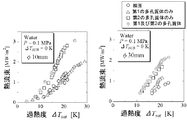
- 3 is a boiling curve obtained in Test Example 2.
- the first porous body is composed of an aggregate of porous nanoparticles
- the second porous body is composed of a porous layer having a mesh structure. is there.
- A) is a heat transfer surface observation photograph after polishing of the heat transfer surface produced in Test Example 3.
- FIG. 4 shows a cooler using a pool boiling method according to the first embodiment.
- the cooler includes a container for storing the working fluid, and a cooling member provided in the container so as to be in contact with the working fluid and to be in contact with the heating element.
- the cooling member has a laminated structure of a first porous body provided on the heating element side and a second porous body provided on the working fluid side.
- FIG. 5 shows a cooling member according to this embodiment.
- 5A is a plan view of the first porous body
- FIG. 5B is a plan view of the second porous body
- FIG. 5C is a cooling member provided at the contact portion.
- the first porous body includes a first working fluid supply unit and a first vapor discharge unit.
- the first working fluid supply unit supplies the working fluid to the contact portion with the heating element by capillary action.
- the first steam discharge unit discharges the steam generated by the heat from the heating element from the contact portion to the second porous body side.
- the first porous body is composed of a porous layer, and has, for example, a mesh structure having a large number of rectangular holes, and a lattice-like porous layer around the rectangular holes.
- the first vapor discharge in which the portion functions as a first working fluid supply unit that supplies the working fluid to the contact portion by capillary action, and the rectangular hole discharges the steam generated at the contact portion to the second porous body side It functions as a part.
- the supply of the working fluid and the discharge of the steam are performed using separate paths in this manner, so that the steam covers the contact portion and the limit heat flux is limited. Can be suppressed. Further, as shown in FIG.
- the second porous body is composed of a porous layer, for example, a mesh structure having a large number of rectangular holes, like the first porous body.
- the lattice-shaped porous layer portion around the rectangular hole functions as a second working fluid supply unit that supplies the working fluid to the first porous body, and the rectangular hole is the first hole. It functions as a second vapor discharge unit that discharges the vapor discharged from the porous body into the working fluid.
- the second porous body has a larger working fluid permeability than the first porous body, has a function of holding the working fluid, and coalesced bubbles stay in the upper portion of the second porous body. In the meantime, it functions so that the working fluid is quickly supplied to the first porous body.
- the second porous body operates more than the permeability of the first porous body by making the pore radius of the porous body larger than the pore radius of the first porous body to facilitate the passage of the working fluid.
- the fluid permeability can be increased.
- the pore radius of the porous body may be a radius of a hole originally provided in each porous body, or may be a radius of a hole formed in each porous body.
- the shape of the pores of the porous body can be various shapes such as a polygonal shape, a circular shape, and an elliptical shape. The radius of the circumscribed circle at.
- the second porous body has a porosity of the porous body larger than that of the first porous body to facilitate the passage of the working fluid, so that the permeability of the first porous body is higher than that of the first porous body.
- the permeability of the working fluid can be increased.
- the porosity of the porous body can be increased, for example, by adjusting the particle size / amount of the binder to be mixed with the metal powder in the manufacturing process of the porous body.
- the working fluid can be a liquid having a surface tension such as water, a low-temperature fluid, a refrigerant, an organic solvent, or the like.
- the size of the hole for releasing the vapor generated at the contact portion into water is preferably small. It can be set to 2000 ⁇ m.
- the gap between the holes for releasing the steam generated at the contact portion into the water is preferably small, and can be, for example, 100 to 1000 ⁇ m. .
- the porous material constituting the first working fluid supply unit in the first porous body may be ceramics such as cordierite or a sintered metal, for example.
- the first porous body supplies the working fluid to the contact portion by capillary action when the liquid evaporates in the first working fluid supply portion, but considering the limit mechanism of liquid supply by capillary force, As the capillary length (ie, the thickness of the first porous body) is thinner, the limit, that is, the “critical heat flux” can be increased.
- FIG. 3 shows a state in which the vapor mass is formed on the contact portion under the high heat flux condition, but the volume of the vapor mass increases with time and eventually cuts off from the contact portion.
- a liquid film having a finite thickness exists between the vapor mass and the contact portion (that is, the bottom of the vapor mass).
- a macro liquid film exists between the vapor mass and the contact portion (that is, the bottom of the vapor mass).
- burnout occurs when the macro liquid film at the bottom of the vapor mass is exhausted and exhausted while the vapor mass remains on the macro liquid film.
- the heat flux at this time is called “limit heat flux”.
- the thickness of the first porous body is preferably thinner from the limit mechanism of liquid supply by capillary force (capillary limit mechanism), but if the thickness is too thin and is approximately the same as the thickness of the macro liquid film, Liquid withering tends to occur near the contact portion of the porous body, and the critical heat flux becomes small.
- the thickness of the porous body provided in the contact portion with the heating element is preferably thin from the viewpoint of the capillary limit mechanism, but if it is thinner than the macro liquid film thickness, the liquid body is liable to wither inside the porous body. There is a problem that the critical heat flux becomes small. Therefore, in the present invention, the porous body provided at the contact portion with the heating element is the first porous body, and the permeability of the working fluid is higher than that of the first porous body (on the working fluid side). A large second porous body is provided. According to such a configuration, the second porous body that supplies the working fluid to the first porous body in an abundant manner between the first porous body and the vapor mass above the first porous body.
- the thickness of the first porous body is reduced, the occurrence of liquid withering is suppressed, and the critical heat flux can be prevented from being reduced.
- the thickness of the second porous body is preferably about 1 to 2 mm or more.
- the second porous body may be formed of ceramics such as cordierite, but is preferably formed of metal from the viewpoint of workability and strength.
- FIG. 5 shows a form in which the first porous body and the second porous body are both circular, and the first and second vapor discharge portions are both lattice-shaped. There is no intention to limit to such a form.
- the first and second vapor discharge portions may be formed in a honeycomb shape, for example.
- FIG. 5 shows the first and second working fluid supply sections and the steam discharge section so as to be orthogonal to the lower contact section and the upper working fluid side. If the section and the steam discharge section respectively provide paths between the surface in contact with the contact section and the surface in contact with the working fluid, they are configured so as to be, for example, a curved path or a bent path, without being orthogonal to each other. May be.
- the rectangular holes of each porous body function as a vapor discharge part, but the shape of the holes is not particularly limited, and other polygonal shapes, circular shapes, oval shapes It may be a shape or the like. Further, the holes may be holes originally provided in each porous body, or may be holes formed in each porous body.
- first porous body and the second porous body is not particularly limited.
- first porous body and the second porous body are both aggregates of porous particles. It may be configured.
- both the 1st porous body and the 2nd porous body may be comprised by the porous layer.
- one of the first porous body and the second porous body may be composed of an aggregate of porous particles, and the other may be composed of a porous layer.
- first porous body and the second porous body are composed of an aggregate of porous particles
- a gap between a plurality of porous particles has a function as a vapor discharge portion, and the gap It is possible to adopt a configuration in which the members around are functioning as a working fluid supply unit.
- the laminated structure of the cooling member is not limited to the one constituted by the first porous body and the second porous body, and the third porous body is further provided on the working fluid side of the second porous body.
- a material body may be provided to form a three-layer structure as a whole.
- the third porous body includes a working fluid supply section that supplies the working fluid to the second porous body, and a steam discharge section that discharges the steam discharged from the second porous body into the working fluid.
- the laminated structure of the cooling member may be configured to have a total of four or more layers by laminating a plurality of porous bodies on the working fluid side of the second porous body.
- a gap region is formed at the contact portion between the first porous body of the cooling member and the heating element.
- the vapor generated on the bottom surface of the first working fluid supply unit of the first porous body proceeds along the bottom surface of the first working fluid supply unit, and then exits to the first vapor discharge unit. It is discharged upward from the steam discharge section.
- the gap region becomes a passage for the vapor generated on the bottom surface of the first porous body, Steam discharge is promoted, and the critical heat flux is improved.
- the gap area may be processed with a rough rough surface, but the gap area necessary for steam discharge is very small, so that the first porous body is simply brought into contact with the contact part.
- a sufficient gap region is formed by the roughness of the surface of the contact portion that is provided from the beginning.
- region is lose
- the entire heating element can be immersed in the working fluid, or a part of the heating element can be partially immersed from the liquid level of the working fluid for cooling.
- the heating element takes various forms depending on cases such as a floating state, a state where it is placed on the bottom surface of the container, and the main point is that the first porous body and the second porous body are immersed in the working fluid.
- the liquid when steam is generated in the working fluid supply section and the contact section of the first porous body, the liquid is forcibly supplied to the contact section by capillary action, so that the container for storing the working fluid such as water is stored.
- the porous body provided at the contact portion with the heating element is the first porous body, and the working fluid permeability is higher on the porous body (on the working fluid side) than the first porous body.
- a second porous body is provided.
- FIG. 6 the schematic diagram of the cooler of the reactor pressure vessel bottom part of the light water reactor which concerns on Embodiment 2 is shown.
- a support ring is attached so as to surround the reactor in the circumferential direction from the side of the reactor, and a honeycomb mounting net (metal mesh) supported by the support ring is attached.
- the honeycomb mounting net may not be made of metal but may be formed of a heat resistant resin.
- a cooling member having a laminated structure of the honeycomb-like first porous body and the second porous body is provided so as to cover the bottom of the reactor pressure vessel. Temporarily fix.
- the honeycomb mounting net is pulled near the support ring to bring the honeycomb mounting net into contact with the bottom of the reactor pressure vessel.
- the cooling member is structured to be held from below by the honeycomb mounting net.
- the honeycomb mounting net may not be a mesh, and may be formed using a plurality of tapes because the construction is simpler. Moreover, a part including the deepest part of the reactor pressure vessel bottom is immersed in a vessel containing water.
- the first porous body and the second porous body of the cooling member have the same structure as in the first embodiment, so as to realize a good critical heat flux and prevent melt-through at the bottom of the reactor pressure vessel. It is possible to realize a critical heat flux of about 2000 kW / m 2 required for the process, and about 2500 kW / m 2 or more beyond that.
- the cooler according to the present invention is particularly suitable for cooling the bottom of the reactor pressure vessel in the event of a reactor accident.
- the cooling member covers a part of the bottom of the reactor pressure vessel.
- the cooling member may be provided so as to cover all of the portion immersed in the vessel containing water at the bottom of the reactor pressure vessel. Good.
- the cooling member provided with the honeycomb-shaped first porous body and the second porous body so as to cover the bottom of the reactor pressure vessel of the second embodiment may be supported without using the honeycomb mounting net.
- the first and second porous bodies are formed by forming the second porous body from metal and fixing its end to the bottom of the reactor pressure vessel, which is a heating element, by welding. May be supported. Welding is preferably spot welding because it is easy to work and provides sufficient support.
- the radiation fin is welded to the heat generating body, and the second porous body may be fixed to the radiation fin by welding. According to such a configuration, the heat from the heat generating element is released from the heat radiation fin, so that the heat generating element can be cooled more favorably.
- both the first porous body and the second porous body may be composed of aggregates of porous particles.
- both the first porous body and the second porous body may be composed of a porous layer.
- either one of the first porous body and the second porous body is composed of an aggregate of porous particles, and the other is composed of a porous layer. May be.
- the porous body is composed of an aggregate of porous particles, the aggregate of porous particles is wrapped with a fine mesh material to such an extent that the particles cannot pass through.
- the said mesh material For example, it can form with the honeycomb mounting
- FIG. 9 shows a cooling device according to the third embodiment.
- the cooling device includes the cooler according to the first embodiment and a capacitor connected to the container. In the condenser, the evaporated working fluid is liquefied and returned to the container.
- the cooling device does not require an external power source such as a pump, and is excellent in compactness and energy saving as the entire device.
- FIG. 10 shows a modification of the cooling device according to the third embodiment. 9 and 10 can be used together with the cooler of the second embodiment.
- the first porous body constituting the cooling member to the second porous body are changed from a porous body having a smaller pore diameter to a porous body having a gradually larger pore diameter.
- the porous body on the side in direct contact with the bulk liquid is preferably formed so that the pore diameter is different from the diameter of fine particles such as dust existing in a large amount of working fluid such as water.
- the porous body on the side in direct contact with the bulk liquid has a pore diameter sufficiently larger or smaller than the diameter of the fine particles.
- a porous body having a large pore diameter is gradually laminated from a porous body having a small pore diameter, and the outermost pore diameter of the porous body is set to be a working fluid. If the particle size of the dust inside is sufficiently larger or smaller than that, the dust particles that have flowed in do not immediately penetrate into the deep part of the porous body, but are formed immediately after entering the porous body.
- FIG. 14 shows a cooling device according to the fifth embodiment.
- the first porous body may be composed of an aggregate of porous nanoparticles
- the second porous body may be composed of a porous layer having a mesh structure.
- FIG. 14A is a plan view of a second porous body composed of a mesh-structured porous layer having a large number of rectangular holes
- FIG. 14B is a cooling member provided at the contact portion.
- the first porous body is composed of an aggregate of nanoparticles having an average particle diameter of 10 to 50 nm. Examples of the nanoparticles that can be used include metals, alloys, oxides, nitrides, carbides, and carbon.
- an aqueous solution in which nanoparticles are diffused is provided by a predetermined means on the heat transfer surface where the first porous body is to be formed, and the state While heating, boil by heating on the heat transfer surface.
- the porous nanoparticles are deposited on the boiling heat transfer surface to form an aggregate, which becomes the first porous body.
- the 2nd porous body comprised by the porous layer which has a mesh structure is provided on the aggregate
- a second porous body is provided on the surface of the heating element, and then the first porous body is provided between the surface of the heating element and the second porous body.
- a body may be provided.
- the second is configured by a porous layer having a mesh structure on the surface of a part immersed in the working liquid of the heating element in which nanoparticles are dispersed in the working fluid.
- the porous body is provided, and the nano particles in the working fluid are precipitated on the heat transfer surface of the heating element by the heat from the heating element to form an aggregate of the porous nanoparticles.
- the cooling member is attached to the surface of the portion of the heating element that is immersed in the working liquid.
- a honeycomb porous body (second porous body) is provided in advance in a pressure vessel of a nuclear reactor, and nanoparticles are supplied and dispersed in the working fluid when an accident occurs. Subsequently, the working fluid containing the nanoparticles boiled on the working fluid side surface (heat transfer surface) of the pressure vessel, so that a set of porous nanoparticles is formed between the heat transfer surface and the second porous body.
- a first porous body composed of the body is formed.
- the aggregate of nanoparticles constituting the first porous body has a large number of pores between or within the particles constituting the first working fluid supply section or the first vapor discharge section.
- the first porous body performs the supply of the working fluid and the discharge of the steam using separate paths, so that the steam covers the contact portion as described with reference to FIG. The occurrence of the problem that the critical heat flux is limited can be suppressed.
- the second porous body functions as a second working fluid supply section in which the lattice-shaped porous layer portion around the rectangular holes supplies the working fluid to the first porous body.
- the holes function as a second vapor discharge unit that discharges the vapor discharged from the first porous body into the working fluid.
- the second porous body has a larger working fluid permeability than the first porous body, has a function of holding the working fluid, and coalesced bubbles stay in the upper portion of the second porous body. In the meantime, it functions so that the working fluid is quickly supplied to the first porous body.
- the first porous body is composed of an aggregate of porous nanoparticles, the wettability of the heat transfer surface is improved, and the second porous layer having a mesh structure is used. By using this porous body, the supply performance of the working fluid to the heat transfer surface becomes better. Thereby, it becomes difficult to produce the dry area
- the present invention can be applied to various electronic devices and other thermal devices having a high heat generation density in addition to cooling of the reactor pressure vessel.
- divertor cooling in fusion reactors high performance of capillary pump loops, semiconductor lasers, data center server cooling, CFC-cooled chopper control devices, power electronics, and the like are conceivable.
- it can be applied to a water-cooled jacket that improves the high-temperature working environment by reducing heat dissipated from the side or bottom of a glass or aluminum melting furnace to the surrounding environment.
- the present invention can be applied to a water-cooled jacket installed on the side of the fire wall or the bottom of the fire wall to reduce damage by cooling the fire wall such as a large garbage incinerator from the outside.
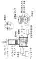
- FIG. 11 shows a schematic diagram of the experimental apparatus.
- the diameter of the contact portion in contact with the working fluid was 30 mm.
- a copper cylinder embedded with a cartridge heater was used as a heating element.
- the amount of heating was controlled by controlling the voltage applied to the cartridge heater with a variable autotransformer.
- the heat flux was calculated from the distance and the thermal conductivity by the Fourier equation.
- the container was a Pyrex (registered trademark) tube having an inner diameter of 87 mm and an outer diameter of 100 mm so that the state of internal boiling could be observed.
- the working liquid was distilled water at a depth of 60 mm and heated with a heater to maintain the saturation temperature.
- the generated steam was condensed by a condenser provided at the upper end of the Pyrex (registered trademark) tube and returned to the container.
- the first porous body of the cooling member a disk (trade name: MF-Millipore) having a mixture of cellulose acetate and cellulose nitrate was used.
- the diameter of the disc of the first porous body was 30 mm, the hole radius was 0.8 ⁇ m, the porosity was 80%, and the plate thickness was 0.15 mm.
- a porous disk of a SUS plate SUS316L was used as the second porous body of the cooling member.
- the diameter of the disk of the second porous body is 30 mm, the hole radius is 10 ⁇ m, the porosity is 70%, the plate thickness is 1 mm, and the transmittance of the second porous body is 10 of that of the first porous body. It was about twice.
- the second porous body was placed on the first porous body having such a configuration to form a cooling member.
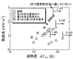
- FIG. 12 shows the boiling curve obtained in the experiment.
- the boiling curve represents the characteristics of boiling heat transfer, and the vertical axis represents the heat flux, and the horizontal axis represents the difference between the heating element temperature and the liquid saturation temperature, that is, the degree of superheat ⁇ Tsat [K] at the contact portion.
- the arrow in the figure indicates the burnout occurrence point where the cooling capacity is significantly deteriorated and the temperature of the contact portion rapidly rises, and the value [MW / m 2 ] of the critical heat flux at that time is shown in the figure.
- the limit heat flux was 0.8 MW / m 2 , but in the case where only the first porous body is installed in the contact portion, the limit The heat flux was 1.46 MW / m 2 , an improvement over the bare surface.
- the first and second porous bodies were installed, the heat could be stably removed even when the critical heat flux was 2.41 MW / m 2 .
- 2.41 MW / m 2 shown in FIG. 12 is not yet the critical heat flux value. From FIG.
- Test Example 2 Subsequently, in order to examine the relationship between the surface roughness of the contact portion surface (heat transfer surface) and the critical heat flux, the experimental apparatus, the first porous body, and the second porous body of Test Example 1 were used. The test was conducted. First, the surface of the contact portion in contact with the working fluid of the experimental apparatus of Test Example 1 is polished with sandpaper (# 40), and the first porous body and the second porous body are provided on the surface in this order. It was set as the cooling member. Further, the surface of the contact portion in contact with the working fluid of the experimental apparatus of Test Example 1 is polished with sandpaper (# 80), and the first porous body and the second porous body are provided in this order on the surface. It was set as the cooling member. Furthermore, without polishing the surface of the contact portion in contact with the working fluid of the experimental apparatus of Test Example 1, a first porous body is provided via an adhesive, and a second porous body is further provided thereon for cooling. It was set as a member.
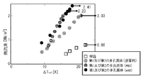
- FIG. 13 shows the boiling curve obtained at this time. From FIG. 13, the surface roughness of the surface of the contact portion (heat transfer surface) was the roughest, and the critical heat flux of the cooling member tested by polishing the surface of the contact member with sandpaper (# 40) was the best.
- Test Example 3 In order to evaluate the critical heat flux related to the cooling member shown in the fifth embodiment using the same type of apparatus as the experimental apparatus shown in FIG. 11, the following tests were performed.
- the diameter of the contact portion in contact with the working fluid was 30 mm and 10 mm.
- a copper cylinder embedded with a cartridge heater was used as a heating element. The amount of heating was controlled by controlling the voltage applied to the cartridge heater with a variable autotransformer.
- the heat flux was calculated from the distance and the thermal conductivity by the Fourier equation.
- the container was a Pyrex (registered trademark) tube having an inner diameter of 87 mm and an outer diameter of 100 mm so that the state of internal boiling could be observed.
- the working liquid was distilled water at a depth of 60 mm and heated with a heater to maintain the saturation temperature.
- the generated steam was condensed by a condenser provided at the upper end of the Pyrex (registered trademark) tube and returned to the container.
- an aggregate of porous nanoparticles was produced as follows. That is, first, in a beaker containing distilled water prepared in advance, titanium dioxide (average particle size 21 nm) weighed with an electronic balance was placed as nanoparticles and dispersed. At this time, the nanoparticle (titanium dioxide) concentration was 0.04 g / L. Next, the heat transfer surface shown in FIG. 11 was provided in the container to supply distilled water, and the water in the container was boiled. The heat transfer surface was polished in advance.
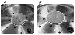
- FIG. 15A shows a heat transfer surface observation photograph after the heat transfer surface polishing.
- FIG. 15B shows a heat transfer surface observation photograph after the nanoparticle coating of the heat transfer surface.
- a porous disk (SUS316L) of a SUS plate was used as a second porous body (porous layer having a mesh structure) of the cooling member.
- the diameter of the disk of the 2nd porous body prepared the thing of 30 mm, and the thing of 10 mm. In all cases, the hole radius was 10 ⁇ m, the porosity was 70%, and the plate thickness was 1 mm.
- the second porous body (porous layer having a mesh structure) having such a configuration was placed on the first porous body (aggregate of porous nanoparticles) to form a cooling member.
- FIG. 16 shows a boiling curve obtained in the experiment.
- the critical heat flux was 1.4 MW / m 2 (heat transfer surface ⁇ 10 mm), 0.9 MW / m 2 (heat transfer surface ⁇ 30 mm).
- the first porous body when installed in only the contact portion is critical heat flux is 2.0 mW / m 2 (heat transfer surface .phi.10 mm), 1.2 MW / m 2 (Heat transfer surface ⁇ 30 mm), which is improved over the bare surface.
- the critical heat flux is 3.1 MW / m 2.
- the heat could be removed stably even at (heat transfer surface ⁇ 10 mm) and 2.2 MW / m 2 (heat transfer surface ⁇ 30 mm). Since this time the heater before the state of the critical heat flux is damaged, 3.1 mW / m 2 as shown in FIG. 16 (heat transfer surface ⁇ 10mm), 2.2MW / m 2 (heat transfer surface .phi.30 mm) is It is not yet the value of critical heat flux.
Landscapes
- Engineering & Computer Science (AREA)
- Physics & Mathematics (AREA)
- General Engineering & Computer Science (AREA)
- Plasma & Fusion (AREA)
- High Energy & Nuclear Physics (AREA)
- Thermal Sciences (AREA)
- Mechanical Engineering (AREA)
- Crystallography & Structural Chemistry (AREA)
- Chemical & Material Sciences (AREA)
- Life Sciences & Earth Sciences (AREA)
- Sustainable Development (AREA)
- Structure Of Emergency Protection For Nuclear Reactors (AREA)
- Cooling Or The Like Of Semiconductors Or Solid State Devices (AREA)
Abstract
簡易な構造で且つ良好な冷却効果を安定して有する冷却器を提供する。冷却器は、作動流体を収容する容器と、容器内において、作動流体と接するように且つ発熱体に対向するように設けられた冷却部材とを備える。冷却部材は、発熱体側に設けられた第1の多孔質体と、作動流体側に設けられた第2の多孔質体とを備えた積層構造に構成されている。第1の多孔質体は、毛細管現象により作動流体を発熱体との接触部に供給する第1の作動流体供給部と、接触部で発生した蒸気を第2の多孔質体側へ排出する第1の蒸気排出部とを備える。第2の多孔質体は、作動流体を第1の多孔質体に供給する第2の作動流体供給部と、第1の多孔質体から排出された蒸気を作動流体中へ排出する第2の蒸気排出部とを備え、第1の多孔質体よりも作動流体の透過率が大きい多孔質体で形成されている。
Description
本発明は、冷却器及びそれを用いた冷却装置、並びに、発熱体の冷却方法に関し、より詳細には沸騰方式による冷却器及びそれを用いた冷却装置、並びに、発熱体の冷却方法に関するものである。
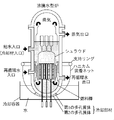
近年、図1に示すような軽水炉の圧力容器において、燃料棒が溶融事故を起こしても、原子炉圧力容器底部を外部から水で冷却してメルトスルーを生じさせない冷却機構が求められており、そのような冷却機構として、沸騰冷却方式によるものが知られている。
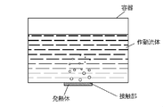
沸騰冷却方式には、プール沸騰方式と、強制流動沸騰方式がある。ここでは、プール沸騰方式による発熱体の一般的な冷却機構について説明する。図2は、従来のプール沸騰方式による冷却器を示している。冷却器は、容器と、容器内に収容された作動流体とを備え、容器は、冷却対象である発熱体との接触部を有する。発熱体において熱が発生し、接触部を通して作動流体に熱が伝わると、接触部の近傍に存在する作動流体が沸騰する。沸騰により蒸気が生じると気液の密度差により接触部に作動流体が供給される。こうして新たに供給された作動流体がさらに蒸発し、発熱体から熱を除去する。プール沸騰方式による冷却器は、強制流動沸騰方式のような液体を循環させるための外部動力源が不要であるため、コンパクト性および省エネルギー性に有利である。
S. G. Kandlikar, M. Shoji, and V. K. Dhir, "Handbook of Phase Change: Boiling and Condensation," Taylor & Francis, 1999
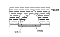
しかしながら、接触部に大きな熱流束が加えられると、従来のプール沸騰方式による冷却器では問題がある。図3にその様子を示す。熱流束が大きくなるにつれて、作動流体の蒸発量が増加し、接触部が蒸気に覆われ始める。接触部が完全に蒸気に覆われて乾燥状態となり、接触部へ作動流体が供給されなくなると、冷却器の冷却能力は著しく劣化する。この状態の熱流束を「限界熱流束」という。
従来のプール沸騰方式による冷却器の限界熱流束は、飽和状態において大気圧・水の条件下の場合1000kW/m2程度であるのに対し(非特許文献1参照)、上記のような軽水炉の原子炉圧力容器底部のメルトスルーを防止するためには、冷却器に少なくとも2000kW/m2程度以上の限界熱流束が求められる。
これに対し、本発明者は、特開2009-139005号公報(特許文献1)において多孔質体を発熱体と冷却容器内の水との間に設けて、多孔質体の毛細管現象により水を発熱体へ供給しつつ、それにより発生した蒸気を容器内の水中へ排出する構造とすることで、簡易な構造で従来の限界熱流束を飛躍的に向上させている。しかしながら、より安全に原子炉圧力容器底部のメルトスルーを防止するためには、冷却効果をさらに高めた冷却器の開発が望まれている。
本発明は、簡易な構造で且つ良好な冷却効果を安定して有する冷却器及びそれを用いた冷却装置、並びに、発熱体の冷却方法を提供することを課題とする。
本発明者は研究を重ねたところ、詳細は後述するが、特許文献1に開示された多孔質体を発熱体側に設けて第1の多孔質体とし、さらに、それに重ねるようにして、作動流体側に、第1の多孔質体よりも透過率が大きい第2の多孔質体とを備えることで、冷却効果をさらに向上させた冷却器を提供することが可能となることを見出した。
すなわち、本発明の一態様は発熱体を冷却するための沸騰方式による冷却器であって、作動流体を収容する容器と、前記容器内において、前記作動流体と接するように且つ前記発熱体に対向するように設けられた冷却部材とを備え、前記冷却部材は、前記発熱体側に設けられた第1の多孔質体と、前記作動流体側に設けられた第2の多孔質体とを備えた積層構造に構成され、前記第1の多孔質体は、毛細管現象により前記作動流体を前記発熱体との接触部に供給する第1の作動流体供給部と、前記接触部で発生した蒸気を前記第2の多孔質体側へ排出する第1の蒸気排出部とを備え、前記第2の多孔質体は、前記作動流体を前記第1の多孔質体に供給する第2の作動流体供給部と、前記第1の多孔質体から排出された蒸気を前記作動流体中へ排出する第2の蒸気排出部とを備え、前記第1の多孔質体よりも前記作動流体の透過率が大きい多孔質体で形成されている冷却器である。
本発明の一実施形態に係る冷却器では、前記第2の多孔質体は、孔半径を前記第1の多孔質体の孔半径より大きくすることで、及び/又は、空隙率を前記第1の多孔質体の空隙率より大きくすることで、前記第1の多孔質体よりも前記作動流体の透過率を大きくしている。
本発明の別の一実施形態に係る冷却器では、前記第1の多孔質体及び前記第2の多孔質体が、いずれも多孔質粒子の集合体で構成されている。
本発明の更に別の一実施形態に係る冷却器では、前記第1の多孔質体及び前記第2の多孔質体が、いずれも多孔質層で構成されている。
本発明の更に別の一実施形態に係る冷却器では、前記第1の多孔質体及び前記第2の多孔質体のいずれか一方が多孔質粒子の集合体で構成されており、他方が多孔質層で構成されている。
本発明の更に別の一実施形態に係る冷却器では、前記第1の多孔質体が多孔質ナノ粒子の集合体で構成されており、前記第2の多孔質体がメッシュ構造を有する多孔質層で構成されている。
本発明の更に別の一実施形態に係る冷却器では、前記第1の多孔質体が多孔質層で構成されており、前記第1の蒸気排出部が、前記多孔質層を貫通する孔である。
本発明の更に別の一実施形態に係る冷却器では、前記第1の多孔質体と、前記発熱体との接触部に隙間領域が形成されている。
本発明の更に別の一実施形態に係る冷却器では、前記第2の多孔質体が金属で形成されている。
本発明の更に別の一実施形態に係る冷却器では、前記金属で形成された第2の多孔質体の端部が前記発熱体に溶接により固定されている。
本発明の更に別の一実施形態に係る冷却器では、前記発熱体に放熱フィンが溶接されており、前記放熱フィンに前記第2の多孔質体が溶接により固定されている。
本発明は別の一態様は、本発明の冷却器と、前記冷却器の容器に接続され、蒸発した作動流体を液化するコンデンサとを備えた冷却装置である。
本発明は更に別の一態様は、作動流体を収容した容器の作動流体中に、発熱体を少なくとも部分的に浸漬して発熱体を冷却する沸騰方式による冷却方法において、前記発熱体の作動液体に浸漬された部分の表面に、前記発熱体側に設けられた第1の多孔質体と、前記作動流体側に設けられた第2の多孔質体とを備えた積層構造に構成された冷却部材であり、前記第1の多孔質体は、毛細管現象により前記作動流体を前記発熱体との接触部に供給する第1の作動流体供給部と、前記接触部で発生した蒸気を前記第2の多孔質体側へ排出する第1の蒸気排出部とを備え、前記第2の多孔質体は、前記作動流体を前記第1の多孔質体に供給する第2の作動流体供給部と、前記第1の多孔質体から排出された蒸気を前記作動流体中へ排出する第2の蒸気排出部とを備え、前記第1の多孔質体よりも前記作動流体の透過率が大きい多孔質体で形成されている冷却部材を装着する発熱体の冷却方法である。
本発明の一実施形態に係る発熱体の冷却方法では、前記作動流体中にナノ粒子を分散させておき、且つ、前記発熱体の作動液体に浸漬された部分の表面に、メッシュ構造を有する多孔質層で構成された前記第2の多孔質体を設けておき、発熱体からの熱によって、前記作動流体中のナノ粒子が沸騰する発熱体の伝熱面上で析出して多孔質ナノ粒子の集合体を構成することで前記第1の多孔質体を前記発熱体と前記第2の多孔質体との間に形成することで、前記発熱体の作動液体に浸漬された部分の表面に前記冷却部材を装着する。
本発明の冷却器及びそれを用いた冷却装置、並びに、発熱体の冷却方法は、少なくとも以下の効果を有する:
(1)原子炉圧力容器底部のメルトスルーを防止するために必要な2000kW/m2程度、さらにはそれを超えて2500kW/m2程度以上の限界熱流束を実現できる。
(2)第1の多孔質体の作動流体供給部と接触部で蒸気が発生すると毛細管現象により強制的に液体が接触部に供給されるので、プール沸騰冷却方式とする場合には水等の作動流体を収容する容器(水槽)は、水の流路やポンプ等を設ける必要が無く、単なる水溜を用いることができ、簡易な構造とすることができ、設置コストやランニングコストが安価となる。
(3)発熱体との接触部に設ける多孔質体の厚さは、毛管限界メカニズムの観点からは薄いほうがよいが、薄すぎると合体泡が多孔質体上部で滞留している間に多孔質体内部で液枯れが生じやすく、限界熱流束が小さくなる。そこで、本発明では発熱体との接触部に設ける多孔質体を第1の多孔質体とし、その上に(作動流体側に)、第1の多孔質体よりも作動流体の透過率が大きい第2の多孔質体を設けている。このような構成によれば、第1の多孔質体とその上方の蒸気塊との間に、作動流体を第1の多孔質体に向かって潤沢に液体を供給する第2の多孔質体が存在するため、第1の多孔質体の厚さを薄くしても、液枯れの発生が抑制され、限界熱流束が小さくなることを防ぐことができる。
(1)原子炉圧力容器底部のメルトスルーを防止するために必要な2000kW/m2程度、さらにはそれを超えて2500kW/m2程度以上の限界熱流束を実現できる。
(2)第1の多孔質体の作動流体供給部と接触部で蒸気が発生すると毛細管現象により強制的に液体が接触部に供給されるので、プール沸騰冷却方式とする場合には水等の作動流体を収容する容器(水槽)は、水の流路やポンプ等を設ける必要が無く、単なる水溜を用いることができ、簡易な構造とすることができ、設置コストやランニングコストが安価となる。
(3)発熱体との接触部に設ける多孔質体の厚さは、毛管限界メカニズムの観点からは薄いほうがよいが、薄すぎると合体泡が多孔質体上部で滞留している間に多孔質体内部で液枯れが生じやすく、限界熱流束が小さくなる。そこで、本発明では発熱体との接触部に設ける多孔質体を第1の多孔質体とし、その上に(作動流体側に)、第1の多孔質体よりも作動流体の透過率が大きい第2の多孔質体を設けている。このような構成によれば、第1の多孔質体とその上方の蒸気塊との間に、作動流体を第1の多孔質体に向かって潤沢に液体を供給する第2の多孔質体が存在するため、第1の多孔質体の厚さを薄くしても、液枯れの発生が抑制され、限界熱流束が小さくなることを防ぐことができる。
以下、図面を参照して本発明の実施形態を詳細に説明する。
(実施形態1)
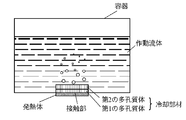
図4は、実施形態1に係るプール沸騰方式による冷却器を示している。冷却器は、作動流体を収容する容器と、容器内において、作動流体と接するように且つ発熱体に対向して接するように設けられた冷却部材とを備える。冷却部材は、発熱体側に設けられた第1の多孔質体と、作動流体側に設けられた第2の多孔質体との積層構造に構成されている。
(実施形態1)
図4は、実施形態1に係るプール沸騰方式による冷却器を示している。冷却器は、作動流体を収容する容器と、容器内において、作動流体と接するように且つ発熱体に対向して接するように設けられた冷却部材とを備える。冷却部材は、発熱体側に設けられた第1の多孔質体と、作動流体側に設けられた第2の多孔質体との積層構造に構成されている。
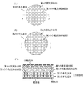
図5は、本実施形態に係る冷却部材を示している。図5(A)は第1の多孔質体の平面図であり、図5(B)は第2の多孔質体の平面図であり、図5(C)は、冷却部材を接触部に設けた状態における5-5断面図である。第1の多孔質体は、図5(A)に示したように、第1の作動流体供給部と第1の蒸気排出部とを備える。第1の作動流体供給部は、毛細管現象により発熱体との接触部に作動流体を供給する。第1の蒸気排出部は、発熱体からの熱により発生した蒸気を、接触部から第2の多孔質体側へ排出する。本実施形態では、第1の多孔質体は多孔質層で構成されており、例えば、多数の矩形状の孔を有するメッシュ構造を有し、矩形状の孔の周囲の格子状の多孔質層部分が毛細管現象により接触部に作動流体を供給する第1の作動流体供給部として機能し、矩形状の孔が接触部で発生した蒸気を第2の多孔質体側へ排出する第1の蒸気排出部として機能する。このように作動流体の供給と蒸気の排出を別個の経路を用いて行うことにより、図3を参照して説明したように、蒸気が接触部を覆ってしまい限界熱流束が制限されるという問題の発生を抑制することができる。また第2の多孔質体は、図5(B)に示すように、第1の多孔質体と同様に、多孔質層で構成されており、例えば、多数の矩形状の孔を有するメッシュ構造を有し、矩形状の孔の周囲の格子状の多孔質層部分が第1の多孔質体に作動流体を供給する第2の作動流体供給部として機能し、矩形状の孔が第1の多孔質体から排出された蒸気を作動流体中へ排出する第2の蒸気排出部として機能する。そして、第2の多孔質体は、第1の多孔質体に比べて作動流体の透過率が大きく、作動流体を保持する機能を有し、第2の多孔質体上部で合体気泡が滞留する間にも、速やかに第1の多孔質体への作動流体の供給が行われるように機能する。
第2の多孔質体は、多孔質体が有する孔半径を第1の多孔質体の孔半径より大きくして作動流体を通しやすくすることで、第1の多孔質体の透過率よりも作動流体の透過率を大きくすることができる。ここで、多孔質体が有する孔半径は、各多孔質体が元々備えている孔の半径であってもよいし、各多孔質体に形成した孔の半径であってもよい。ここで、多孔質体の孔の形状は、多角形状、円形状、楕円形状等、種々の形状とすることが可能であるが、本発明の「孔半径」は、そのような種々の孔形状における外接円の半径を示す。さらに、第2の多孔質体は、多孔質体の空隙率を第1の多孔質体の空隙率より大きくして作動流体を通しやすくすることで、第1の多孔質体の透過率よりも作動流体の透過率を大きくすることができる。多孔質体の空隙率は、例えば、多孔質体の製造工程において金属粉末と混合させるバインダーの粒径・量などを調整することによって大きくすることができる。
作動流体は、たとえば水、低温流体、冷媒、有機溶媒等の表面張力を有する液体とすることができる。
第1の多孔質体の形状としては、多孔質体の接触部への接触面積が大きくなるため接触部で発生した蒸気を水中へ逃がすための孔の大きさは小さいほうがよく、例えば、100~2000μmとすることができる。また、多孔質底部を通過する場合の圧力損失を小さくできるため、接触部で発生した蒸気を水中へ逃がすための孔と孔の間隔は小さい方がよく、例えば、100~1000μmとすることができる。
第1の多孔質体における第1の作動流体供給部を構成する多孔質は、たとえばコーディライト等のセラミックスまたは焼結金属とすることができる。特に酸化物等の濡れ性の良い多孔質体、または、プラズマ照射等の濡れ性が向上する加工が施された多孔質体で構成されるのが望ましい。
第1の多孔質体は、第1の作動流体供給部において、液体の蒸発が起これば毛細管現象により接触部に作動流体を供給するが、毛管力による液体供給の限界メカニズムを考慮すれば、毛細管の長さ(すなわち、第1の多孔質体の厚さ)は薄いほうがよりその限界、すなわち「限界熱流束」を高くすることができる。一方、図3において、高熱流束条件下の接触部上で蒸気塊が形成される様子を示したが、その蒸気塊の体積は時間と共に増大し、やがて接触部から切断離脱する。この蒸気塊と接触部近傍をより詳細に説明すれば、蒸気塊と接触部の間(すなわち蒸気塊の底部)には、有限厚さの液膜(一般に、マクロ液膜と呼ばれる)が存在する。このような高熱流束条件下においては、蒸気塊がマクロ液膜上に滞留している間に蒸気塊底部のマクロ液膜が蒸発消耗し尽くすときにバーンアウトが発生する。このときの熱流束が「限界熱流束」と呼ばれる。第1の多孔質体の厚さは、上述の通り毛管力による液体供給の限界メカニズム(毛管限界メカニズム)から薄いほうがよいが、薄過ぎてマクロ液膜の厚さと同程度であると、第1多孔質体の接触部近傍で液枯れが生じやすく、限界熱流束が小さくなる。
このように、発熱体との接触部に設ける多孔質体の厚さは、毛管限界メカニズムの観点からは薄いほうがよいが、マクロ液膜の厚さより薄いと多孔質体内部で液枯れが生じやすく、限界熱流束が小さくなるという問題がある。そこで、本発明では、発熱体との接触部に設ける多孔質体を第1の多孔質体とし、その上に(作動流体側に)、第1の多孔質体よりも作動流体の透過率が大きい第2の多孔質体を設けている。このような構成によれば、第1の多孔質体とその上方の蒸気塊との間に、作動流体を第1の多孔質体に向かって潤沢に液体を供給する第2の多孔質体が存在するため、第1の多孔質体の厚さを薄くしても、液枯れの発生が抑制され、限界熱流束が小さくなることを防ぐことができる。また、第2の多孔質体の液供給量は多いほど好ましいため、第2の多孔質体の厚みも大きくするのが好ましい。具体的には、例えば、第1の多孔質体の厚さを100μm程度と薄くする場合、第2の多孔質体の厚さは1~2mm以上程度とするのが好ましい。
第2の多孔質体は、コーディライト等のセラミックスで形成してもよいが、特に加工性や強度の点から金属で形成するのが好ましい。特に酸化物等の濡れ性の良い多孔質体、または、プラズマ照射等の濡れ性が向上する加工が施された多孔質体で構成されるのが望ましい。
なお、図5には第1の多孔質体及び第2の多孔質体がいずれもが円形であり、第1及び第2の蒸気排出部がいずれも格子状である形態を示したが、このような形態に限定する意図はない。第1及び第2の蒸気排出部は、例えばハニカム状としてもよい。また図5には第1及び第2の作動流体供給部及び蒸気排出部が下方の接触部及び上方の作動流体側に直交するように図示してあるが、第1及び第2の作動流体供給部及び蒸気排出部は、接触部に接する面と作動流体に接する面との間の経路をそれぞれ与えるものであれば、直交せずに、例えば、湾曲した経路や折れ曲がった経路となるように構成されていてもよい。また、本実施形態では、上述のように、各多孔質体が有する矩形状の孔が蒸気排出部として機能するが、当該孔の形状は特に限定されず、その他の多角形状、円形状、楕円形状等であってもよい。また、当該孔は各多孔質体が元々備えている孔であってもよいし、各多孔質体に形成した孔であってもよい。
また、第1の多孔質体と第2の多孔質体との形態は特に限定されず、例えば、第1の多孔質体及び第2の多孔質体が、いずれも多孔質粒子の集合体で構成されていてもよい。また、第1の多孔質体及び第2の多孔質体が、いずれも多孔質層で構成されていてもよい。さらに、第1の多孔質体及び第2の多孔質体のいずれか一方が多孔質粒子の集合体で構成されており、他方が多孔質層で構成されていてもよい。第1の多孔質体、第2の多孔質体が、多孔質粒子の集合体で構成されている場合、例えば複数の多孔質粒子間の隙間が蒸気排出部としての機能を有し、当該隙間の周囲の部材が作動流体供給部として機能する構成とすることができる。
また、冷却部材の積層構造は、第1の多孔質体と、第2の多孔質体とで構成されたものに限定されず、第2の多孔質体の作動流体側にさらに第3の多孔質体を設けて、全体で3層の積層構造としてもよい。この場合、第3の多孔質体は、作動流体を第2の多孔質体に供給する作動流体供給部と、第2の多孔質体から排出された蒸気を作動流体中へ排出する蒸気排出部とを備えている。同様に、冷却部材の積層構造は、第2の多孔質体の作動流体側に複数の多孔質体を積層させて全体で4層以上の構成としてもよい。
冷却部材の第1の多孔質体と、発熱体との接触部に隙間領域が形成されているのが好ましい。第1の多孔質体の第1の作動流体供給部の底面で生じた蒸気は、第1の作動流体供給部の底面に沿って進むことで第1の蒸気排出部へ出て、第1の蒸気排出部から上方へ向かって排出される。ここで、冷却部材の第1の多孔質体と、発熱体との接触部に隙間領域が形成されていると、当該隙間領域が第1の多孔質体の底面で生じた蒸気の通路となり、蒸気の排出が促進され、限界熱流束が向上する。当該隙間領域は、接触部表面をあえて粗面に加工してもよいが、蒸気の排出に必要な隙間領域はごく僅かであるため、単に第1の多孔質体を接触部に接触させるだけで、はじめから有する接触部の表面の粗さで十分な隙間領域が形成される。なお、隙間領域が無くなるため蒸気の排出性は下がるが、第1の多孔質体は接着剤で接触部に固定してあってもよい。
また、本発明の別の態様としては、発熱体全体を作動流体中に浸漬する、または発熱体の一部を作動流体の液面から一部浸漬して冷却を行うこともできる。この場合には、発熱体は浮遊した状態、容器底面に載置された状態など場合により種々の形態をとるが、要は作動流体に浸漬されている部分に第1の多孔質体と第2の多孔質体とを備えた積層構造を有する冷却部材を取り付けることにより、前記例と同様にして冷却を行うことができる。
本発明によれば、第1の多孔質体の作動流体供給部と接触部で蒸気が発生すると毛細管現象により強制的に液体が接触部に供給されるので、水等の作動流体を収容する容器(水槽)は、プール沸騰冷却方式とする場合には水の流路等を設ける必要が無く、単なる水溜を用いることができ、さらにはポンプが不要となり、簡易な構造とすることができ、設置コストやランニングコストが安価となる。また、本発明では発熱体との接触部に設ける多孔質体を第1の多孔質体とし、その上に(作動流体側に)、第1の多孔質体よりも作動流体の透過率が大きい第2の多孔質体を設けている。このような構成により、第1の多孔質体とその上方の蒸気塊との間に、作動流体を第1の多孔質体に向かって潤沢に液体を供給する第2の多孔質体が存在するため、第1の多孔質体の厚さを薄くしても、液枯れの発生が抑制され、限界熱流束が小さくなることを防ぐことができる。なお、設置コスト、ランニングコストはプール沸騰冷却方式に比してかかるが、流路を設け、ポンプで作動流体を循環させる強制流動沸騰冷却の場合にも、同様な方法で限界熱流束の低下を防ぐことができる。
(実施形態2)
図6に、実施形態2に係る軽水炉の原子炉圧力容器底部の冷却器の模式図を示す。原子炉の側方から周方向に原子炉を囲むように支持リングが取り付けられ、支持リングに支持されたハニカム装着ネット(金属メッシュ)が取り付けられている。ハニカム装着ネットは、金属製でなくてもよく、耐熱樹脂で形成してもよい。原子炉圧力容器底部の冷却器の取り付け方法としては、まず、ハニカム状の第1多孔質体及び第2多孔質体との積層構造を有する冷却部材を、原子炉圧力容器底部を覆うように設け、仮止めする。次に、支持リングからハニカム装着ネットを下ろして原子炉圧力容器底部を覆った後に、支持リング近傍でハニカム装着ネットを引き寄せてハニカム装着ネットを原子炉圧力容器底部に接触させる。こうすることで、簡便に原子炉圧力容器底部に冷却器を取り付けることができる。冷却部材は、上記ハニカム装着ネットによって下から保持される構造となっている。ハニカム装着ネットはメッシュでなくてもよく、施工がより簡便であるため複数のテープを用いて形成してもよい。また、原子炉圧力容器底部の最深部を含む一部が水を収容した容器内に浸漬されている。冷却部材の第1多孔質体及び第2多孔質体は、実施形態1と同様の構造を有しており、良好な限界熱流束を実現し、原子炉圧力容器底部のメルトスルーを防止するために必要な2000kW/m2程度、さらにはそれを超えて2500kW/m2程度以上の限界熱流束を実現できる。このように、本発明に係る冷却器は、特に原子炉事故時の原子炉圧力容器の底部の冷却に好適である。また、図6では、冷却部材を原子炉圧力容器底部の一部を覆っているが、原子炉圧力容器底部の、水を収容した容器内に浸漬された部分の全てを覆うように設けてもよい。
図6に、実施形態2に係る軽水炉の原子炉圧力容器底部の冷却器の模式図を示す。原子炉の側方から周方向に原子炉を囲むように支持リングが取り付けられ、支持リングに支持されたハニカム装着ネット(金属メッシュ)が取り付けられている。ハニカム装着ネットは、金属製でなくてもよく、耐熱樹脂で形成してもよい。原子炉圧力容器底部の冷却器の取り付け方法としては、まず、ハニカム状の第1多孔質体及び第2多孔質体との積層構造を有する冷却部材を、原子炉圧力容器底部を覆うように設け、仮止めする。次に、支持リングからハニカム装着ネットを下ろして原子炉圧力容器底部を覆った後に、支持リング近傍でハニカム装着ネットを引き寄せてハニカム装着ネットを原子炉圧力容器底部に接触させる。こうすることで、簡便に原子炉圧力容器底部に冷却器を取り付けることができる。冷却部材は、上記ハニカム装着ネットによって下から保持される構造となっている。ハニカム装着ネットはメッシュでなくてもよく、施工がより簡便であるため複数のテープを用いて形成してもよい。また、原子炉圧力容器底部の最深部を含む一部が水を収容した容器内に浸漬されている。冷却部材の第1多孔質体及び第2多孔質体は、実施形態1と同様の構造を有しており、良好な限界熱流束を実現し、原子炉圧力容器底部のメルトスルーを防止するために必要な2000kW/m2程度、さらにはそれを超えて2500kW/m2程度以上の限界熱流束を実現できる。このように、本発明に係る冷却器は、特に原子炉事故時の原子炉圧力容器の底部の冷却に好適である。また、図6では、冷却部材を原子炉圧力容器底部の一部を覆っているが、原子炉圧力容器底部の、水を収容した容器内に浸漬された部分の全てを覆うように設けてもよい。
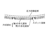
実施形態2の原子炉圧力容器底部を覆うようにハニカム状の第1多孔質体及び第2多孔質体を備えた冷却部材は、ハニカム装着ネットを用いないで支持されてもよい。例えば、図7に示すように、第2の多孔質体を金属で形成し、その端部を発熱体である原子炉圧力容器底部に溶接により固定することで、第1及び2の多孔質体が支持されてもよい。溶接は、作業が容易であって十分な支持力が得られるため、スポット溶接であるのが好ましい。また、発熱体に放熱フィンが溶接されており、放熱フィンに第2の多孔質体が溶接により固定されていてもよい。このような構成によれば、発熱体からの熱が放熱フィンから放出されることで、より良好に発熱体の冷却を行うことができる。
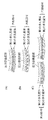
また、実施形態2において、図8(A)に示すように第1の多孔質体及び第2の多孔質体が、いずれも多孔質粒子の集合体で構成されていてもよい。また、図8(B)に示すように第1の多孔質体及び第2の多孔質体が、いずれも多孔質層で構成されていてもよい。さらに、図8(C)に示すように第1の多孔質体及び第2の多孔質体のいずれか一方が多孔質粒子の集合体で構成されており、他方が多孔質層で構成されていてもよい。図8において、多孔質体が多孔質粒子の集合体で構成されている場合、多孔質粒子の集合体は、当該粒子が通り抜けられない程度の目の細かいメッシュ材で包まれている。当該メッシュ材としては、特に限定しないが、例えば、金属製、或いは耐熱樹脂製のハニカム装着ネット等で形成することができる。
(実施形態3)
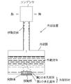
図9は、実施形態3に係る冷却装置を示している。冷却装置は、実施形態1に係る冷却器と、容器に接続されたコンデンサとを備える。コンデンサにおいて、蒸発した作動流体が液化されて、容器に戻る。冷却装置は、ポンプなどの外部動力源を必要とせず、装置全体としてのコンパクト性および省エネルギー性が優れている。図10は、実施形態3に係る冷却装置の変形形態を示している。なお、図9および10の構成を実施形態2の冷却器とともに用いることもできる。
図9は、実施形態3に係る冷却装置を示している。冷却装置は、実施形態1に係る冷却器と、容器に接続されたコンデンサとを備える。コンデンサにおいて、蒸発した作動流体が液化されて、容器に戻る。冷却装置は、ポンプなどの外部動力源を必要とせず、装置全体としてのコンパクト性および省エネルギー性が優れている。図10は、実施形態3に係る冷却装置の変形形態を示している。なお、図9および10の構成を実施形態2の冷却器とともに用いることもできる。
(実施形態4)
本発明の冷却装置は、実施形態4として、冷却部材を構成する第1の多孔質体から第2の多孔質体までを、孔径が小さい多孔質体から、徐々に孔径が大きい多孔質体が段階的に積層されるように構成してもよい。また、このときバルクの液体に直接接する側の多孔質体の細孔径を水等の作動流体中に多く存在するゴミ等の微粒子の直径と異なるように、好ましくは大きく異なるように形成するのが好ましい。例えば、バルクの液体に直接接する側の多孔質体の細孔径を当該微粒子の直径より十分大きく、又は、十分小さく形成するのが好ましい。このような構成によれば、作動流体中に存在する微粒子が多孔質体内の深部にまで入り込んで発生する目詰まり現象を抑制する効果が期待でき、多孔質体による伝熱面への液体供給効果を長時間維持する効果が得られる。原理的には、例えば、孔径が小さい多孔質体から、徐々に孔径が大きい多孔質体が段階的に積層されるように構成され、且つ、多孔質体の最も外側の細孔径が、作動流体中のゴミの粒子径がより十分大きい又は十分小さいと、流入してきたゴミの粒子は、すぐに多孔質体内部の深部まで侵入せずに、多孔質体内に入ってすぐの部位に形成される澱み等の影響で、多孔質体の入口付近から溜まっていく。従って、多孔質体の最も外側の300μmの細孔から目詰まりすることとなり、微粒子が多孔質体内部の深部まで侵入して多孔質体内部にまで目詰まりを形成することが良好に抑制される。
本発明の冷却装置は、実施形態4として、冷却部材を構成する第1の多孔質体から第2の多孔質体までを、孔径が小さい多孔質体から、徐々に孔径が大きい多孔質体が段階的に積層されるように構成してもよい。また、このときバルクの液体に直接接する側の多孔質体の細孔径を水等の作動流体中に多く存在するゴミ等の微粒子の直径と異なるように、好ましくは大きく異なるように形成するのが好ましい。例えば、バルクの液体に直接接する側の多孔質体の細孔径を当該微粒子の直径より十分大きく、又は、十分小さく形成するのが好ましい。このような構成によれば、作動流体中に存在する微粒子が多孔質体内の深部にまで入り込んで発生する目詰まり現象を抑制する効果が期待でき、多孔質体による伝熱面への液体供給効果を長時間維持する効果が得られる。原理的には、例えば、孔径が小さい多孔質体から、徐々に孔径が大きい多孔質体が段階的に積層されるように構成され、且つ、多孔質体の最も外側の細孔径が、作動流体中のゴミの粒子径がより十分大きい又は十分小さいと、流入してきたゴミの粒子は、すぐに多孔質体内部の深部まで侵入せずに、多孔質体内に入ってすぐの部位に形成される澱み等の影響で、多孔質体の入口付近から溜まっていく。従って、多孔質体の最も外側の300μmの細孔から目詰まりすることとなり、微粒子が多孔質体内部の深部まで侵入して多孔質体内部にまで目詰まりを形成することが良好に抑制される。
(実施形態5)
図14は、実施形態5に係る冷却装置を示している。図14に示すように、第1の多孔質体が多孔質ナノ粒子の集合体で構成されており、第2の多孔質体がメッシュ構造を有する多孔質層で構成されていてもよい。図14(A)は多数の矩形状の孔を有するメッシュ構造の多孔質層で構成された第2の多孔質体の平面図であり、図14(B)は、冷却部材を接触部に設けた状態における5-5断面図である。第1の多孔質体は、平均粒径10~50nmのナノ粒子の集合体で構成されている。ナノ粒子としては、例えば金属、合金、酸化物、窒化物、炭化物、炭素等を用いることができる。
図14は、実施形態5に係る冷却装置を示している。図14に示すように、第1の多孔質体が多孔質ナノ粒子の集合体で構成されており、第2の多孔質体がメッシュ構造を有する多孔質層で構成されていてもよい。図14(A)は多数の矩形状の孔を有するメッシュ構造の多孔質層で構成された第2の多孔質体の平面図であり、図14(B)は、冷却部材を接触部に設けた状態における5-5断面図である。第1の多孔質体は、平均粒径10~50nmのナノ粒子の集合体で構成されている。ナノ粒子としては、例えば金属、合金、酸化物、窒化物、炭化物、炭素等を用いることができる。
実施形態5に係る冷却部材の設置方法としては、例えば、ナノ粒子を拡散させた水溶液を、第1の多孔質体を形成させたい位置である伝熱面上に所定の手段で設け、その状態を保ちながら伝熱面上で加熱により沸騰させる。このようにして多孔質ナノ粒子が沸騰する伝熱面上で析出して集合体を構成し、これが第1の多孔質体となる。次に、当該多孔質ナノ粒子の集合体上にメッシュ構造を有する多孔質層で構成した第2の多孔質体を設ける。これにより、多孔質ナノ粒子の集合体で構成された第1の多孔質体と、メッシュ構造を有する多孔質層で構成された第2の多孔質体とで構成された冷却部材を設けることができる。また、当該冷却部材を設ける方法としては、発熱体の表面に第2の多孔質体を設けておき、続いて、発熱体の表面と第2の多孔質体との間に第1の多孔質体を設けてもよい。このような構成としては、例えば、作動流体中にナノ粒子を分散させておき、且つ、発熱体の作動液体に浸漬された部分の表面に、メッシュ構造を有する多孔質層で構成された第2の多孔質体を設けておき、発熱体からの熱によって、作動流体中のナノ粒子が沸騰する発熱体の伝熱面上で析出して多孔質ナノ粒子の集合体を構成することで第1の多孔質体を発熱体と第2の多孔質体との間に形成することで、発熱体の作動液体に浸漬された部分の表面に冷却部材を装着する。具体的には、例えば、原子炉の圧力容器にハニカム多孔質体(第2の多孔質体)を予め設けておき、事故発生時に作動流体にナノ粒子を供給して分散させる。続いて、圧力容器の作動流体側表面(伝熱面)でナノ粒子を含んだ作動流体が沸騰することで、伝熱面表面と第2の多孔質体との間に多孔質ナノ粒子の集合体で構成された第1の多孔質体が形成される。
実施形態5において、第1の多孔質体を構成するナノ粒子の集合体が、粒子間或いは粒子内の多数の細孔が、第1の作動流体供給部又は第1の蒸気排出部を構成している。本実施形態でも、第1の多孔質体が、作動流体の供給と蒸気の排出を別個の経路を用いて行うことにより、図3を参照して説明したように、蒸気が接触部を覆ってしまい限界熱流束が制限されるという問題の発生を抑制することができる。また第2の多孔質体は、矩形状の孔の周囲の格子状の多孔質層部分が第1の多孔質体に作動流体を供給する第2の作動流体供給部として機能し、矩形状の孔が第1の多孔質体から排出された蒸気を作動流体中へ排出する第2の蒸気排出部として機能する。そして、第2の多孔質体は、第1の多孔質体に比べて作動流体の透過率が大きく、作動流体を保持する機能を有し、第2の多孔質体上部で合体気泡が滞留する間にも、速やかに第1の多孔質体への作動流体の供給が行われるように機能する。また、実施形態5では、第1の多孔質体が多孔質ナノ粒子の集合体で構成されているため、伝熱面の濡れ性が良好となり、メッシュ構造を有する多孔質層で構成した第2の多孔質体を用いて、より伝熱面への作動流体の供給性が良好となる。これにより、伝熱面の乾燥領域が生じ難くなり、限界熱流束が小さくなることを防ぐことができる。
本発明は、原子炉圧力容器の冷却の他、種々の電子機器、その他の高発熱密度を有する熱機器全般に適用可能である。たとえば、核融合炉のダイバータ冷却、キャピラリーポンプループの高性能化、半導体レーザ、データセンターのサーバの冷却、フロン冷却式チョッパ制御装置、パワー電子機器等が考えられる。または、ガラスやアルミの溶融炉の側部や底部から周囲環境へ放散する熱を節減して、高温作業環境を改善する水冷ジャケットに適用可能である。さらに、大型ごみ焼却炉等の耐火壁を外部から冷却して損傷を軽減するための、耐火壁側部や耐火壁底部に設置する水冷ジャケットに適用可能である。
以下に本発明を実施例でさらに詳細に説明するが、本発明はこれらに限定されるものではない。
(試験例1)
図11に実験装置の概略図を示す。作動流体と接する接触部の直径を30mmとした。発熱体として、カートリッジヒータが埋め込まれた銅円柱を用いた。カートリッジヒータに印可する電圧を可変単巻変圧器でコントロールすることで加熱量を制御した。接触部からそれぞれ5.4mm、11.4mmの銅円柱中心軸上に設置した2つのφ0.5K型シース熱電対からの出力を用いて外挿して接触部の過熱度を、指示温度差と設定距離及び熱伝導率からフーリエの式で熱流束を求めた。容器は、内径87mm、外形100mmのパイレックス(登録商標)チューブとし、内部沸騰の様相を観察できるようにした。作動液体は、蒸留水を深さが60mmとなるようにし、ヒータで加熱して飽和温度に維持した。発生した蒸気は、パイレックス(登録商標)チューブの上端に設けたコンデンサで凝縮させて容器内に戻した。
図11に実験装置の概略図を示す。作動流体と接する接触部の直径を30mmとした。発熱体として、カートリッジヒータが埋め込まれた銅円柱を用いた。カートリッジヒータに印可する電圧を可変単巻変圧器でコントロールすることで加熱量を制御した。接触部からそれぞれ5.4mm、11.4mmの銅円柱中心軸上に設置した2つのφ0.5K型シース熱電対からの出力を用いて外挿して接触部の過熱度を、指示温度差と設定距離及び熱伝導率からフーリエの式で熱流束を求めた。容器は、内径87mm、外形100mmのパイレックス(登録商標)チューブとし、内部沸騰の様相を観察できるようにした。作動液体は、蒸留水を深さが60mmとなるようにし、ヒータで加熱して飽和温度に維持した。発生した蒸気は、パイレックス(登録商標)チューブの上端に設けたコンデンサで凝縮させて容器内に戻した。
冷却部材の第1の多孔質体として、組成が酢酸セルロースと硝酸セルロースの混合物の円板(商品名:MF-ミリポア)を使用した。第1の多孔質体の円板の直径は30mm、孔半径は0.8μm、空隙率は80%、板厚は0.15mmであった。冷却部材の第2の多孔質体として、SUS板の多孔質体の円板(SUS316L)を使用した。第2の多孔質体の円板の直径は30mm、孔半径は10μm、空隙率は70%、板厚は1mmであり、第2の多孔質体の透過率は第1の多孔質体の10倍程度であった。
このような構成の第1の多孔質体上に第2の多孔質体を載せ、冷却部材とした。
このような構成の第1の多孔質体上に第2の多孔質体を載せ、冷却部材とした。
実験は、大気圧(0.1MPa)のもとで、カードリッジヒータの電圧を5Vずつ上げながら加熱を行い、十分定常状態になったのを確認して、熱電対の出力電圧を記録した。ここで定常状態か否かは、20分間の温度変化が1K以下であるか否かにより判断した。この操作を定常状態が保てなくなるまで繰り返した。上述の冷却部材を設置した場合に加えて、冷却部材を設置しない場合(裸面)、第1の多孔質体のみ、及び、第2の多孔質体のみ設置した場合についても比較のため実験を行った。
図12に実験で得られた沸騰曲線を示す。沸騰曲線とは、沸騰伝熱の特性を表し、縦軸に熱流束、横軸に発熱体温度と液体の飽和温度との差、すなわち接触部の過熱度ΔTsat[K]をとるものである。図中の矢印は、冷却能力が著しく劣化し接触部の温度が急上昇する点であるバーンアウト発生点を示し、その時の限界熱流束の値[MW/m2]を図中に示してある。接触部に何も設置しない場合、すなわち裸面の場合には、限界熱流束は0.8MW/m2であったが、第1の多孔質体のみを接触部に設置した場合には、限界熱流束は1.46MW/m2となり、裸面の場合より向上した。一方、第1及び第2の多孔質体を設置した場合には、限界熱流束は2.41MW/m2でも安定して除熱することができた。なお、このとき限界熱流束の状態となる前にヒータが破損したため、図12で示した2.41MW/m2は、まだ限界熱流束の値ではない。図12から、冷却部材を設けた場合は、他の場合に比べて限界熱流束が非常に高く、目標となる2.5MW/m2に近い結果が得られた。さらに第2の多孔質体の影響を検討するために、第2の多孔質体のみを設置した場合についても実験を行った。その結果、限界熱流束は、1.60MW/m2となり、第1及び第2の多孔質体を設置した場合の限界熱流束より、小さい値となった.したがって、第1及び第2の多孔質体を設置した場合が最も限界熱流束が高くなることがわかった。
(試験例2)
続いて、接触部表面(伝熱面)の表面粗さと限界熱流束との関係を検討するため、試験例1の実験装置、第1の多孔質体、第2の多孔質体を用いて以下の試験を行った。
まず、試験例1の実験装置の作動流体と接する接触部の表面をサンドペーパー(♯40)で研磨し、その上に第1の多孔質体、第2の多孔質体をこの順で設けて冷却部材とした。また、試験例1の実験装置の作動流体と接する接触部の表面をサンドペーパー(♯80)で研磨し、その上に第1の多孔質体、第2の多孔質体をこの順で設けて冷却部材とした。さらに、試験例1の実験装置の作動流体と接する接触部の表面を研磨しないで、接着剤を介して第1の多孔質体を設け、さらにその上に第2の多孔質体を設けて冷却部材とした。
続いて、接触部表面(伝熱面)の表面粗さと限界熱流束との関係を検討するため、試験例1の実験装置、第1の多孔質体、第2の多孔質体を用いて以下の試験を行った。
まず、試験例1の実験装置の作動流体と接する接触部の表面をサンドペーパー(♯40)で研磨し、その上に第1の多孔質体、第2の多孔質体をこの順で設けて冷却部材とした。また、試験例1の実験装置の作動流体と接する接触部の表面をサンドペーパー(♯80)で研磨し、その上に第1の多孔質体、第2の多孔質体をこの順で設けて冷却部材とした。さらに、試験例1の実験装置の作動流体と接する接触部の表面を研磨しないで、接着剤を介して第1の多孔質体を設け、さらにその上に第2の多孔質体を設けて冷却部材とした。
これらの冷却部材について、試験例1と同様の手順にて沸騰曲線を得た。図13にこのとき得られた沸騰曲線を示す。図13より、最も接触部表面(伝熱面)の表面粗さが粗い、接触部材の表面をサンドペーパー(♯40)で研磨して試験した冷却部材の限界熱流束が最も良好であった。
(試験例3)
図11に示した実験装置と同タイプの装置を用いて、実施形態5で示した冷却部材に係る限界熱流束を評価するため、以下の試験を行った。試験例3では、作動流体と接する接触部の直径を30mm、及び、10mmとした。発熱体として、カートリッジヒータが埋め込まれた銅円柱を用いた。カートリッジヒータに印加する電圧を可変単巻変圧器でコントロールすることで加熱量を制御した。接触部からそれぞれ9.94mm、15.16mmの銅円柱中心軸上に設置した2つのφ0.5K型シース熱電対からの出力を用いて外挿して接触部の過熱度を、指示温度差と設定距離及び熱伝導率からフーリエの式で熱流束を求めた。容器は、内径87mm、外形100mmのパイレックス(登録商標)チューブとし、内部沸騰の様相を観察できるようにした。作動液体は、蒸留水を深さが60mmとなるようにし、ヒータで加熱して飽和温度に維持した。発生した蒸気は、パイレックス(登録商標)チューブの上端に設けたコンデンサで凝縮させて容器内に戻した。
図11に示した実験装置と同タイプの装置を用いて、実施形態5で示した冷却部材に係る限界熱流束を評価するため、以下の試験を行った。試験例3では、作動流体と接する接触部の直径を30mm、及び、10mmとした。発熱体として、カートリッジヒータが埋め込まれた銅円柱を用いた。カートリッジヒータに印加する電圧を可変単巻変圧器でコントロールすることで加熱量を制御した。接触部からそれぞれ9.94mm、15.16mmの銅円柱中心軸上に設置した2つのφ0.5K型シース熱電対からの出力を用いて外挿して接触部の過熱度を、指示温度差と設定距離及び熱伝導率からフーリエの式で熱流束を求めた。容器は、内径87mm、外形100mmのパイレックス(登録商標)チューブとし、内部沸騰の様相を観察できるようにした。作動液体は、蒸留水を深さが60mmとなるようにし、ヒータで加熱して飽和温度に維持した。発生した蒸気は、パイレックス(登録商標)チューブの上端に設けたコンデンサで凝縮させて容器内に戻した。
冷却部材の第1の多孔質体として、以下のようにして、多孔質ナノ粒子の集合体を作製した。すなわち、まず、あらかじめ準備した蒸留水の入ったビーカー中に、ナノ粒子として、電子天秤で秤量した二酸化チタン(平均粒径21nm)を入れて分散させた。このとき、ナノ粒子(二酸化チタン)濃度は0.04g/Lであった。次に、図11で示す伝熱面を容器内に設けて蒸留水を供給し、当該容器内の水を沸騰させた。なお、伝熱面はあらかじめ研磨しておいた。図15(a)に、伝熱面研磨後の伝熱面観察写真を示す。続いて、沸騰水の入った容器内に前述のナノ粒子が分散した水を注入した。このまま20分間の沸騰を続けた後、ナノ粒子の分散した水を容器から取り出し、伝熱面を蒸留水で洗浄した。このようにして、伝熱面がナノ粒子でコーティングされる。当該ナノ粒子のコーティング層が、伝熱面上に形成された第1の多孔質体(多孔質ナノ粒子の集合体)を構成している。図15(b)に、伝熱面のナノ粒子コーティング後の伝熱面観察写真を示す。
次に、冷却部材の第2の多孔質体(メッシュ構造を有する多孔質層)として、SUS板の多孔質体の円板(SUS316L)を使用した。第2の多孔質体の円板の直径は30mmのものと10mmのものとを用意した。いずれも、孔半径は10μm、空隙率は70%、板厚は1mmであった。
このような構成の第2の多孔質体(メッシュ構造を有する多孔質層)を第1の多孔質体(多孔質ナノ粒子の集合体)上に載せ、冷却部材とした。
次に、冷却部材の第2の多孔質体(メッシュ構造を有する多孔質層)として、SUS板の多孔質体の円板(SUS316L)を使用した。第2の多孔質体の円板の直径は30mmのものと10mmのものとを用意した。いずれも、孔半径は10μm、空隙率は70%、板厚は1mmであった。
このような構成の第2の多孔質体(メッシュ構造を有する多孔質層)を第1の多孔質体(多孔質ナノ粒子の集合体)上に載せ、冷却部材とした。
実験は、大気圧(0.1MPa)のもとで、カードリッジヒータの電圧を5Vずつ上げながら加熱を行い、十分定常状態になったのを確認して、熱電対の出力電圧を記録した。ここで定常状態か否かは、20分間の温度変化が1K以下であるか否かにより判断した。この操作を定常状態が保てなくなるまで繰り返した。上述の冷却部材を設置した場合に加えて、冷却部材を設置しない場合(裸面)、第1の多孔質体(多孔質ナノ粒子の集合体)のみ、及び、第2の多孔質体(メッシュ構造を有する多孔質層)のみ設置した場合についても比較のため実験を行った。
図16に実験で得られた沸騰曲線を示す。接触部に何も設置しない場合、すなわち裸面の場合には、限界熱流束は1.4MW/m2(伝熱面φ10mm)、0.9MW/m2(伝熱面φ30mm)であったが、第1の多孔質体(多孔質ナノ粒子の集合体)のみを接触部に設置した場合には、限界熱流束は2.0MW/m2(伝熱面φ10mm)、1.2MW/m2(伝熱面φ30mm)となり、裸面の場合より向上した。一方、第1の多孔質体(多孔質ナノ粒子の集合体)及び第2の多孔質体(メッシュ構造を有する多孔質層)を設置した場合には、限界熱流束は3.1MW/m2(伝熱面φ10mm)、2.2MW/m2(伝熱面φ30mm)でも安定して除熱することができた。なお、このとき限界熱流束の状態となる前にヒータが破損したため、図16で示した3.1MW/m2(伝熱面φ10mm)、2.2MW/m2(伝熱面φ30mm)は、まだ限界熱流束の値ではない。さらに第2の多孔質体(メッシュ構造を有する多孔質層)のみを設置した場合についても実験を行った。その結果、限界熱流束は、2.8MW/m2(伝熱面φ10mm)、1.7MW/m2(伝熱面φ30mm)となり、第1の多孔質体(多孔質ナノ粒子の集合体)及び第2の多孔質体(メッシュ構造を有する多孔質層)を設置した場合の限界熱流束より、小さい値となった。したがって、第1の多孔質体(多孔質ナノ粒子の集合体)及び第2の多孔質体(メッシュ構造を有する多孔質層)を設置した場合が最も限界熱流束が高くなることがわかった。
Claims (14)
- 発熱体を冷却するための沸騰方式による冷却器であって、
作動流体を収容する容器と、
前記容器内において、前記作動流体と接するように且つ前記発熱体に対向するように設けられた冷却部材と
を備え、
前記冷却部材は、前記発熱体側に設けられた第1の多孔質体と、前記作動流体側に設けられた第2の多孔質体とを備えた積層構造に構成され、
前記第1の多孔質体は、毛細管現象により前記作動流体を前記発熱体との接触部に供給する第1の作動流体供給部と、前記接触部で発生した蒸気を前記第2の多孔質体側へ排出する第1の蒸気排出部とを備え、
前記第2の多孔質体は、前記作動流体を前記第1の多孔質体に供給する第2の作動流体供給部と、前記第1の多孔質体から排出された蒸気を前記作動流体中へ排出する第2の蒸気排出部とを備え、前記第1の多孔質体よりも前記作動流体の透過率が大きい多孔質体で形成されている冷却器。 - 前記第2の多孔質体は、孔半径を前記第1の多孔質体の孔半径より大きくすることで、及び/又は、空隙率を前記第1の多孔質体の空隙率より大きくすることで、前記第1の多孔質体よりも前記作動流体の透過率を大きくした請求項1に記載の冷却器。
- 前記第1の多孔質体及び前記第2の多孔質体が、いずれも多孔質粒子の集合体で構成されている請求項1又は2に記載の冷却器。
- 前記第1の多孔質体及び前記第2の多孔質体が、いずれも多孔質層で構成されている請求項1又は2に記載の冷却器。
- 前記第1の多孔質体及び前記第2の多孔質体のいずれか一方が多孔質粒子の集合体で構成されており、他方が多孔質層で構成されている請求項1又は2に記載の冷却器。
- 前記第1の多孔質体が多孔質ナノ粒子の集合体で構成されており、前記第2の多孔質体がメッシュ構造を有する多孔質層で構成されている請求項5に記載の冷却器。
- 前記第1の多孔質体が多孔質層で構成されており、前記第1の蒸気排出部が、前記多孔質層を貫通する孔である請求項4又は5に記載の冷却器。
- 前記第1の多孔質体と、前記発熱体との接触部に隙間領域が形成されている請求項1~7のいずれかに記載の冷却器。
- 前記第2の多孔質体が金属で形成されている請求項1~8のいずれかに記載の冷却器。
- 前記金属で形成された第2の多孔質体の端部が前記発熱体に溶接により固定されている請求項9に記載の冷却器。
- 前記発熱体に放熱フィンが溶接されており、前記放熱フィンに前記第2の多孔質体が溶接により固定されている請求項9に記載の冷却器。
- 請求項1~11のいずれかに記載の冷却器と、
前記冷却器の容器に接続され、蒸発した作動流体を液化するコンデンサと
を備えた冷却装置。 - 作動流体を収容した容器の作動流体中に、発熱体を少なくとも部分的に浸漬して発熱体を冷却する沸騰方式による冷却方法において、
前記発熱体の作動液体に浸漬された部分の表面に、
前記発熱体側に設けられた第1の多孔質体と、前記作動流体側に設けられた第2の多孔質体とを備えた積層構造に構成された冷却部材であり、
前記第1の多孔質体は、毛細管現象により前記作動流体を前記発熱体との接触部に供給する第1の作動流体供給部と、前記接触部で発生した蒸気を前記第2の多孔質体側へ排出する第1の蒸気排出部とを備え、
前記第2の多孔質体は、前記作動流体を前記第1の多孔質体に供給する第2の作動流体供給部と、前記第1の多孔質体から排出された蒸気を前記作動流体中へ排出する第2の蒸気排出部とを備え、前記第1の多孔質体よりも前記作動流体の透過率が大きい多孔質体で形成されている冷却部材を装着する発熱体の冷却方法。 - 前記作動流体中にナノ粒子を分散させておき、且つ、前記発熱体の作動液体に浸漬された部分の表面に、メッシュ構造を有する多孔質層で構成された前記第2の多孔質体を設けておき、
発熱体からの熱によって、前記作動流体中のナノ粒子が沸騰する発熱体の伝熱面上で析出して多孔質ナノ粒子の集合体を構成することで前記第1の多孔質体を前記発熱体と前記第2の多孔質体との間に形成することで、前記発熱体の作動液体に浸漬された部分の表面に前記冷却部材を装着する請求項13に記載の発熱体の冷却方法。
Priority Applications (3)
| Application Number | Priority Date | Filing Date | Title |
|---|---|---|---|
| US14/777,700 US20160273839A1 (en) | 2013-03-18 | 2014-02-06 | Cooler, cooling apparatus using the same, and method for cooling heat generation element |
| EP14767940.1A EP2977700B1 (en) | 2013-03-18 | 2014-02-06 | Cooler, cooling device using same, and method for cooling heat generation element |
| US15/959,766 US20180299207A1 (en) | 2013-03-18 | 2018-04-23 | Cooler, cooling apparatus using the same, and method for cooling heat generation element |
Applications Claiming Priority (4)
| Application Number | Priority Date | Filing Date | Title |
|---|---|---|---|
| JP2013-055533 | 2013-03-18 | ||
| JP2013055533 | 2013-03-18 | ||
| JP2013262872A JP5882292B2 (ja) | 2013-03-18 | 2013-12-19 | 冷却器及びそれを用いた冷却装置、並びに、発熱体の冷却方法 |
| JP2013-262872 | 2013-12-19 |
Related Child Applications (2)
| Application Number | Title | Priority Date | Filing Date |
|---|---|---|---|
| US14/777,700 A-371-Of-International US20160273839A1 (en) | 2013-03-18 | 2014-02-06 | Cooler, cooling apparatus using the same, and method for cooling heat generation element |
| US15/959,766 Division US20180299207A1 (en) | 2013-03-18 | 2018-04-23 | Cooler, cooling apparatus using the same, and method for cooling heat generation element |
Publications (1)
| Publication Number | Publication Date |
|---|---|
| WO2014148137A1 true WO2014148137A1 (ja) | 2014-09-25 |
Family
ID=51579832
Family Applications (1)
| Application Number | Title | Priority Date | Filing Date |
|---|---|---|---|
| PCT/JP2014/052783 Ceased WO2014148137A1 (ja) | 2013-03-18 | 2014-02-06 | 冷却器及びそれを用いた冷却装置、並びに、発熱体の冷却方法 |
Country Status (4)
| Country | Link |
|---|---|
| US (2) | US20160273839A1 (ja) |
| EP (1) | EP2977700B1 (ja) |
| JP (1) | JP5882292B2 (ja) |
| WO (1) | WO2014148137A1 (ja) |
Cited By (3)
| Publication number | Priority date | Publication date | Assignee | Title |
|---|---|---|---|---|
| WO2015174423A1 (ja) * | 2014-05-12 | 2015-11-19 | 国立大学法人横浜国立大学 | 冷却器及びそれを用いた冷却装置、並びに、発熱体の冷却方法 |
| WO2016051569A1 (ja) * | 2014-10-02 | 2016-04-07 | 富士通株式会社 | 蒸発器、冷却装置及び電子装置 |
| WO2025150329A1 (ja) * | 2024-01-10 | 2025-07-17 | 国立研究開発法人産業技術総合研究所 | 伝熱構造体 |
Families Citing this family (4)
| Publication number | Priority date | Publication date | Assignee | Title |
|---|---|---|---|---|
| JP2016040505A (ja) * | 2014-08-12 | 2016-03-24 | 国立大学法人横浜国立大学 | 冷却器及びそれを用いた冷却装置、並びに、発熱体の冷却方法 |
| JP2016217684A (ja) * | 2015-05-26 | 2016-12-22 | 国立大学法人横浜国立大学 | 冷却器及びそれを用いた冷却装置、並びに、発熱体の冷却方法 |
| JP6756470B2 (ja) * | 2015-10-05 | 2020-09-16 | 三菱重工業株式会社 | 原子炉および原子力プラント |
| US12018893B2 (en) * | 2017-11-06 | 2024-06-25 | Zuta-Core Ltd. | Evaporator including a porous unit |
Citations (10)
| Publication number | Priority date | Publication date | Assignee | Title |
|---|---|---|---|---|
| JP2000049266A (ja) * | 1998-05-25 | 2000-02-18 | Denso Corp | 沸騰冷却装置 |
| US20050280996A1 (en) * | 2004-06-16 | 2005-12-22 | Hakan Erturk | Heat dissipating device with enhanced boiling/condensation structure |
| US20070240855A1 (en) * | 2006-04-14 | 2007-10-18 | Foxconn Technology Co., Ltd. | Heat pipe with composite capillary wick structure |
| JP2008039378A (ja) * | 2006-07-14 | 2008-02-21 | Central Glass Co Ltd | ヒートパイプ |
| JP2009139005A (ja) | 2007-12-05 | 2009-06-25 | Yokohama National Univ | 冷却器及びその冷却器を備える冷却装置 |
| JP2009250810A (ja) * | 2008-04-07 | 2009-10-29 | Seiko Epson Corp | 電子部品の温度制御装置およびハンドラ装置 |
| JP2010151354A (ja) * | 2008-12-24 | 2010-07-08 | Sony Corp | 熱輸送デバイス及び電子機器 |
| JP2012032276A (ja) * | 2010-07-30 | 2012-02-16 | Toshiba Corp | 炉心溶融物冷却装置および格納容器 |
| JP2012043954A (ja) * | 2010-08-18 | 2012-03-01 | Fujitsu Ltd | 半導体装置 |
| JP2013243249A (ja) * | 2012-05-21 | 2013-12-05 | Denso Corp | 沸騰冷却用伝熱面および沸騰冷却装置 |
Family Cites Families (14)
| Publication number | Priority date | Publication date | Assignee | Title |
|---|---|---|---|---|
| US7051793B1 (en) * | 1998-04-20 | 2006-05-30 | Jurgen Schulz-Harder | Cooler for electrical components |
| US6227287B1 (en) * | 1998-05-25 | 2001-05-08 | Denso Corporation | Cooling apparatus by boiling and cooling refrigerant |
| US6994152B2 (en) * | 2003-06-26 | 2006-02-07 | Thermal Corp. | Brazed wick for a heat transfer device |
| CN100437006C (zh) * | 2005-08-12 | 2008-11-26 | 富准精密工业(深圳)有限公司 | 热管之制造方法 |
| FR2896614B1 (fr) * | 2006-01-25 | 2010-10-15 | Commissariat Energie Atomique | Procede et dispositif de fermeture en piscine d'un etui charge avec du combustible nucleaire irradie |
| BRPI0708517A2 (pt) * | 2006-03-03 | 2011-05-31 | Richard Furberg | camada porosa |
| US8561673B2 (en) * | 2006-09-26 | 2013-10-22 | Olantra Fund X L.L.C. | Sealed self-contained fluidic cooling device |
| US9920530B2 (en) * | 2007-04-17 | 2018-03-20 | University Of Virginia Patent Foundation | Heat-managing composite structures |
| EP2009146A1 (en) * | 2007-06-22 | 2008-12-31 | Danmarks Tekniske Universitet - DTU | A microporous coating or structure and a process for producing it |
| US8170173B2 (en) * | 2007-11-15 | 2012-05-01 | The State Of Oregon Acting By And Through The State Board Of Higher Education On Behalf Of Oregon State University | Passive emergency feedwater system |
| US7832462B2 (en) * | 2008-03-31 | 2010-11-16 | Alcatel-Lucent Usa Inc. | Thermal energy transfer device |
| US8235096B1 (en) * | 2009-04-07 | 2012-08-07 | University Of Central Florida Research Foundation, Inc. | Hydrophilic particle enhanced phase change-based heat exchange |
| TW201127266A (en) * | 2010-01-20 | 2011-08-01 | Pegatron Corp | Vapor chamber and manufacturing method thereof |
| DE102011011688A1 (de) * | 2011-02-18 | 2012-08-23 | Fraunhofer-Gesellschaft zur Förderung der angewandten Forschung e.V. | Verfahren zur Beschichtung einer Wärmetauscherstruktur, beschichtete Wärmetauscherstruktur und deren Verwendung |
-
2013
- 2013-12-19 JP JP2013262872A patent/JP5882292B2/ja active Active
-
2014
- 2014-02-06 EP EP14767940.1A patent/EP2977700B1/en active Active
- 2014-02-06 WO PCT/JP2014/052783 patent/WO2014148137A1/ja not_active Ceased
- 2014-02-06 US US14/777,700 patent/US20160273839A1/en not_active Abandoned
-
2018
- 2018-04-23 US US15/959,766 patent/US20180299207A1/en not_active Abandoned
Patent Citations (10)
| Publication number | Priority date | Publication date | Assignee | Title |
|---|---|---|---|---|
| JP2000049266A (ja) * | 1998-05-25 | 2000-02-18 | Denso Corp | 沸騰冷却装置 |
| US20050280996A1 (en) * | 2004-06-16 | 2005-12-22 | Hakan Erturk | Heat dissipating device with enhanced boiling/condensation structure |
| US20070240855A1 (en) * | 2006-04-14 | 2007-10-18 | Foxconn Technology Co., Ltd. | Heat pipe with composite capillary wick structure |
| JP2008039378A (ja) * | 2006-07-14 | 2008-02-21 | Central Glass Co Ltd | ヒートパイプ |
| JP2009139005A (ja) | 2007-12-05 | 2009-06-25 | Yokohama National Univ | 冷却器及びその冷却器を備える冷却装置 |
| JP2009250810A (ja) * | 2008-04-07 | 2009-10-29 | Seiko Epson Corp | 電子部品の温度制御装置およびハンドラ装置 |
| JP2010151354A (ja) * | 2008-12-24 | 2010-07-08 | Sony Corp | 熱輸送デバイス及び電子機器 |
| JP2012032276A (ja) * | 2010-07-30 | 2012-02-16 | Toshiba Corp | 炉心溶融物冷却装置および格納容器 |
| JP2012043954A (ja) * | 2010-08-18 | 2012-03-01 | Fujitsu Ltd | 半導体装置 |
| JP2013243249A (ja) * | 2012-05-21 | 2013-12-05 | Denso Corp | 沸騰冷却用伝熱面および沸騰冷却装置 |
Non-Patent Citations (2)
| Title |
|---|
| S. G. KANDLIKAR; M. SHOJI; V. K. DHIR: "Handbook of Phase Change: Boiling and Condensation", 1999, TAYLOR FRANCIS |
| See also references of EP2977700A4 |
Cited By (5)
| Publication number | Priority date | Publication date | Assignee | Title |
|---|---|---|---|---|
| WO2015174423A1 (ja) * | 2014-05-12 | 2015-11-19 | 国立大学法人横浜国立大学 | 冷却器及びそれを用いた冷却装置、並びに、発熱体の冷却方法 |
| JPWO2015174423A1 (ja) * | 2014-05-12 | 2017-04-20 | 国立大学法人横浜国立大学 | 冷却器及びそれを用いた冷却装置、並びに、発熱体の冷却方法 |
| WO2016051569A1 (ja) * | 2014-10-02 | 2016-04-07 | 富士通株式会社 | 蒸発器、冷却装置及び電子装置 |
| TWI576556B (zh) * | 2014-10-02 | 2017-04-01 | 富士通股份有限公司 | 蒸發器、冷卻裝置及電子裝置 |
| WO2025150329A1 (ja) * | 2024-01-10 | 2025-07-17 | 国立研究開発法人産業技術総合研究所 | 伝熱構造体 |
Also Published As
| Publication number | Publication date |
|---|---|
| EP2977700A4 (en) | 2016-11-23 |
| JP2014206365A (ja) | 2014-10-30 |
| US20180299207A1 (en) | 2018-10-18 |
| JP5882292B2 (ja) | 2016-03-09 |
| US20160273839A1 (en) | 2016-09-22 |
| EP2977700B1 (en) | 2017-05-31 |
| EP2977700A1 (en) | 2016-01-27 |
Similar Documents
| Publication | Publication Date | Title |
|---|---|---|
| JP5882292B2 (ja) | 冷却器及びそれを用いた冷却装置、並びに、発熱体の冷却方法 | |
| US7828046B2 (en) | Hybrid wicking materials for use in high performance heat pipes | |
| JP7514339B2 (ja) | 原子炉の蒸気発生器 | |
| US8235096B1 (en) | Hydrophilic particle enhanced phase change-based heat exchange | |
| JP6283410B2 (ja) | 冷却器及びそれを用いた冷却装置、並びに、発熱体の冷却方法 | |
| Kruse et al. | Effects of femtosecond laser surface processed nanoparticle layers on pool boiling heat transfer performance | |
| US10619947B2 (en) | Heat exchanger | |
| JP2016040505A (ja) | 冷却器及びそれを用いた冷却装置、並びに、発熱体の冷却方法 | |
| JP7835503B2 (ja) | 複合ウィック構造を含むヒートパイプ及び関連する製造方法 | |
| Mori et al. | Enhancement of critical heat flux using spherical porous bodies in saturated pool boiling of nanofluid | |
| JPWO2016121778A1 (ja) | 蓄熱容器及び蓄熱容器を備えた蓄熱装置 | |
| JP2009139005A (ja) | 冷却器及びその冷却器を備える冷却装置 | |
| JP2014206365A5 (ja) | ||
| JP2012154644A (ja) | 原子炉格納容器の熱輸送装置およびその方法 | |
| CN106287623A (zh) | 相变蓄热式蒸汽蓄热器 | |
| WO2014141853A1 (ja) | 貯蔵核燃料の冷却システム | |
| JP4281619B2 (ja) | 蒸気エンジン | |
| JP2016217684A (ja) | 冷却器及びそれを用いた冷却装置、並びに、発熱体の冷却方法 | |
| Patel et al. | Electrohydrodynamic conduction pumping-driven liquid film flow boiling on bare and nanofiber-enhanced surfaces | |
| Vasil’ev et al. | Vapor agglomerates and dry spots as precursors of the subcooled liquid boiling crisis in a channel | |
| JP7705678B1 (ja) | 蓄熱体、蓄熱装置および蓄熱システム | |
| CN114659397A (zh) | 传热设备以及制造这种设备的方法 | |
| JP2017219269A (ja) | 発熱体の冷却方法 | |
| CN102056468A (zh) | 一种冷凝辐射散热板 | |
| US6222112B1 (en) | Thermionic converter temperature controller |
Legal Events
| Date | Code | Title | Description |
|---|---|---|---|
| 121 | Ep: the epo has been informed by wipo that ep was designated in this application |
Ref document number: 14767940 Country of ref document: EP Kind code of ref document: A1 |
|
| DPE1 | Request for preliminary examination filed after expiration of 19th month from priority date (pct application filed from 20040101) | ||
| WWE | Wipo information: entry into national phase |
Ref document number: 14777700 Country of ref document: US |
|
| NENP | Non-entry into the national phase |
Ref country code: DE |
|
| REEP | Request for entry into the european phase |
Ref document number: 2014767940 Country of ref document: EP |
|
| WWE | Wipo information: entry into national phase |
Ref document number: 2014767940 Country of ref document: EP |