WO2014148253A1 - マルチコアファイバ用光接続器 - Google Patents
マルチコアファイバ用光接続器 Download PDFInfo
- Publication number
- WO2014148253A1 WO2014148253A1 PCT/JP2014/055578 JP2014055578W WO2014148253A1 WO 2014148253 A1 WO2014148253 A1 WO 2014148253A1 JP 2014055578 W JP2014055578 W JP 2014055578W WO 2014148253 A1 WO2014148253 A1 WO 2014148253A1
- Authority
- WO
- WIPO (PCT)
- Prior art keywords
- ferrule
- optical connector
- plug frame
- optical
- fiber
- Prior art date
- Legal status (The legal status is an assumption and is not a legal conclusion. Google has not performed a legal analysis and makes no representation as to the accuracy of the status listed.)
- Ceased
Links
Images




Classifications
-
- G—PHYSICS
- G02—OPTICS
- G02B—OPTICAL ELEMENTS, SYSTEMS OR APPARATUS
- G02B6/00—Light guides; Structural details of arrangements comprising light guides and other optical elements, e.g. couplings
- G02B6/24—Coupling light guides
- G02B6/36—Mechanical coupling means
- G02B6/38—Mechanical coupling means having fibre to fibre mating means
- G02B6/3807—Dismountable connectors, i.e. comprising plugs
- G02B6/3869—Mounting ferrules to connector body, i.e. plugs
-
- G—PHYSICS
- G02—OPTICS
- G02B—OPTICAL ELEMENTS, SYSTEMS OR APPARATUS
- G02B6/00—Light guides; Structural details of arrangements comprising light guides and other optical elements, e.g. couplings
- G02B6/24—Coupling light guides
- G02B6/36—Mechanical coupling means
- G02B6/38—Mechanical coupling means having fibre to fibre mating means
- G02B6/3807—Dismountable connectors, i.e. comprising plugs
- G02B6/381—Dismountable connectors, i.e. comprising plugs of the ferrule type, e.g. fibre ends embedded in ferrules, connecting a pair of fibres
-
- G—PHYSICS
- G02—OPTICS
- G02B—OPTICAL ELEMENTS, SYSTEMS OR APPARATUS
- G02B6/00—Light guides; Structural details of arrangements comprising light guides and other optical elements, e.g. couplings
- G02B6/24—Coupling light guides
- G02B6/36—Mechanical coupling means
- G02B6/38—Mechanical coupling means having fibre to fibre mating means
- G02B6/3807—Dismountable connectors, i.e. comprising plugs
- G02B6/3873—Connectors using guide surfaces for aligning ferrule ends, e.g. tubes, sleeves, V-grooves, rods, pins, balls
- G02B6/3885—Multicore or multichannel optical connectors, i.e. one single ferrule containing more than one fibre, e.g. ribbon type
-
- G—PHYSICS
- G02—OPTICS
- G02B—OPTICAL ELEMENTS, SYSTEMS OR APPARATUS
- G02B6/00—Light guides; Structural details of arrangements comprising light guides and other optical elements, e.g. couplings
- G02B6/24—Coupling light guides
- G02B6/36—Mechanical coupling means
- G02B6/38—Mechanical coupling means having fibre to fibre mating means
- G02B6/3807—Dismountable connectors, i.e. comprising plugs
- G02B6/3873—Connectors using guide surfaces for aligning ferrule ends, e.g. tubes, sleeves, V-grooves, rods, pins, balls
- G02B6/3874—Connectors using guide surfaces for aligning ferrule ends, e.g. tubes, sleeves, V-grooves, rods, pins, balls using tubes, sleeves to align ferrules
- G02B6/3877—Split sleeves
Definitions
- the present invention relates to an optical connector for a multi-core fiber.
- optical connector In order to communicate using multi-core fiber as a transmission line, there is an optical connector (connector) that can connect multi-core fibers with low loss and can be used without loss even after repeated mounting and removal. Necessary.
- JP-A 2010-286548 Patent Document 3
- 2010-286718 Patent Document 4
- 2011-158768 Patent Document 5
- Multi-core fibers have multiple cores in addition to the center. For this reason, if the axial misalignment of the multi-core fiber (deviation due to rotational movement about the axis) occurs, the cores of these cores are misaligned, resulting in connection loss. Each time the multi-core fiber to be connected is detached, the connection loss changes each time the axial orientation is deviated. Therefore, a connector that does not cause misalignment of multi-core fibers is desired.
- the present invention is basically based on the knowledge that axial misalignment of the multicore fiber can be prevented by pressurizing the flange portion of the ferrule accommodating the multicore fiber from a plurality of directions.
- it is based on the knowledge that it is possible to prevent axial misalignment of the multi-core fiber by providing a flat surface on the ferrule flange and pressurizing the flat surface of the ferrule using a leaf spring structure.
- a structure for pressurizing the flat surface of the ferrule flange can be easily provided by integrally molding the leaf spring structure in the plug frame of the existing optical fiber connector.
- the present invention relates to an optical connector 17 including a ferrule 13 that holds a multi-core fiber 11 and a plug frame 15 that houses the ferrule 13.
- the ferrule 13 of the optical connector 17 has at least one flat surface 19 on the outer peripheral surface.
- the plug frame 15 has a leaf spring structure 21 for pressing the flat surface 19.
- the leaf spring structure 21 is integrally formed in the plug frame 15.
- the optical connector of the present invention prevents a rotational movement around the ferrule axis by providing a flat surface on the flange of the ferrule and pressurizing it from the plug frame side using a leaf spring structure.
- the rotational motion of the multi-core fiber can be prevented.
- the member which pressurizes a flat surface is a leaf
- the optical connector of the present invention presses the flat surface of the ferrule flange by a leaf spring structure, the position of the multi-core fiber in the Z-axis direction can be moved. For this reason, even when the ferrule is pushed in by pressure to bring the fibers into physical contact, the Z-axis position can be moved while preventing the multi-core fiber from rotating about the axis.
- the optical connector of the present invention is formed by integrally molding the leaf spring structure in the plug frame of the standard optical connector, it is necessary to separately attach a part for pressing the flat surface of the ferrule flange to the inside of the plug frame. Therefore, without increasing the number of parts, it is possible to use parts of the standard optical connector for parts other than the plug frame, and it is possible to provide an inexpensive multi-core fiber optical connector.
- the preferred optical connector of the present invention is one in which four flat surfaces 19 a, 19 b, 19 c, 19 d exist on the outer peripheral surface of the ferrule 13.
- the plug frame 15 corresponds to the four flat surfaces 19a, 19b, 19c, and 19d, and has four leaf spring structures 21a, 21b, and 21b for pressing the four flat surfaces 19a, 19b, 19c, and 19d, respectively. 21c and 21d.
- the four leaf spring structures 21a, 21b, 21c, and 21d corresponding to the four flat surfaces 19a, 19b, 19c, and 19d, it is possible to more effectively prevent the axial misalignment of the multi-core fiber. Can do.
- the preferred optical connector of the present invention is one in which the outer end 23 of the ferrule 13 is inserted into an optical adapter having a split sleeve 25. In this way, the outer end 23 of the ferrule 13 is inserted into the split sleeve 25, and another optical connector is inserted into the opposite end of the split sleeve 25. Two multi-core fibers can be connected.
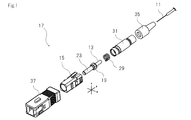
- FIG. 1 is an exploded perspective view of the optical connector of the present invention.
- FIG. 2 is a perspective view showing a mounting example of the optical connector of the present invention.
- FIG. 3A is a cross-sectional view taken along the line AA in FIG.
- FIG. 3B is an enlarged view of B in FIG.
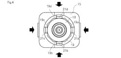
- FIG. 4 is a conceptual diagram when the plug frame of the present invention accommodates a ferrule.
- FIG. 5 is a conceptual diagram for explaining a multi-core fiber connection method using the optical connector of the present invention.
- FIG. 6 is a conceptual diagram when two multi-core fibers are connected using the optical connector of the present invention.
- FIG. 1 is an exploded perspective view of the optical connector of the present invention.
- FIG. 2 is a perspective view showing a mounting example of the optical connector of the present invention.
- FIG. 3A is a cross-sectional view taken along the line AA in FIG.
- FIG. 3B is an enlarged view of B in FIG.
- FIG. 4 is a conceptual diagram when the plug frame of the present invention accommodates a ferrule.
- the optical connector 17 of the present invention is fitted to the plug frame 15 via a ferrule 13 that holds and accommodates the optical fiber 11, a plug frame 15 that accommodates the ferrule 13, and a coil spring 29. It comprises a stop ring 31 to be mated, a connector boot 35, and a knob 37 for housing the above components.
- the optical connector 17 is an optical component used to connect a multi-core fiber and a single mode fiber or multi-core fibers.
- the core arrangement of the multi-cores is the same.
- the corresponding cores of the two multi-core fibers are optically connected by using the optical connector of the present invention.
- the multi-core fiber 11 is an optical fiber including a plurality of cores in one fiber as disclosed in the above-described patent document.
- An example of the multi-core fiber 11 is a fiber having a central core and one or more cores existing around the central core.
- the multi-core fiber 11 does not necessarily have a core at the center.
- the multi-core fiber used in the present invention may be a multi-core fiber having a core in which 2 to 4 (or more) cores are symmetrically arranged.
- the central core means a core existing at the center position of the multi-core fiber.
- the distance between the cores is, for example, 30 ⁇ m or more and 60 ⁇ m or less.
- the distance between cores means the distance from the center of a core to the center of an adjacent core.
- the ferrule 13 is a known optical fiber holding optical component.
- the ferrule 13 is a container for housing a part of the multi-core fiber 11 therein.
- the ferrule 13 is provided in the end part of the multi-core fiber 11, and is used in order to connect another optical fiber.
- the ferrule 13 may be one member or two or more members.
- a ferrule flange 19 is provided at the end portion of the ferrule body on a substantially cylindrical shape (column).
- the plug frame 15 is a container for accommodating the ferrule 13 therein.
- the plug frame 15 is not particularly limited as long as the leaf spring structures 21 a, 21 b, 21 c, and 21 d for applying pressure to the ferrule 13 are integrally formed therein and the ferrule 13 can be accommodated in the plug frame 15.
- An example of the plug frame 15 is a main body of the optical connector.
- the plug frame 15 is integrally formed by a mold using a resin such as nylon resin, polybutylene terephthalate (PBT) resin, or LCP resin (liquid crystal polymer).
- the ferrule 13 in the optical connector 17 of the present invention has at least one flat surface 19 on the outer peripheral surface.
- the flat surface may be approximately flat.
- the flat portion may be formed like the bottom portion of the groove.
- four grooves may be provided at positions rotated 90 degrees around the axis.
- the ferrule flange 19 is pressed by a leaf spring structure.
- the plug frame 15 has a leaf spring structure 21 for pressing the flat surface 19. As shown in FIG. 3, the leaf spring structure 21 is integrally formed in the plug frame 15.
- the flat surface 19 is provided on the outer peripheral surface of the ferrule 13, and it is pressurized from the plug frame 15 side using the leaf spring structure 21, thereby preventing rotational movement around the ferrule axis, The rotational movement of the fiber can be prevented.
- the optical connector 17 of the present invention contacts and pressurizes the flat surface of the outer periphery of the ferrule 13 by the leaf spring structure 21, the X, Y, and Z axis positions of the multicore fiber 11 can be moved. it can. For this reason, as described above, the X, Y, and Z axis positions can be moved while preventing the multi-core fiber from rotating about the axis.
- the optical connector 17 of the present invention is formed by integrally molding the leaf spring structure 21 in the plug frame 15, it is necessary to separately attach a component for pressing the flat surface 19 on the outer periphery of the ferrule 13 to the inside of the plug frame. Disappear.
- the optical connector 17 of the present invention it is not necessary to attach components including springs for pressurizing the flat surfaces 19 a, 19 b, 19 c, 19 d on the outer periphery of the ferrule 13 to the inside of the plug frame 15.
- a structure for pressurizing the flat surface on the outer periphery of the ferrule can be easily provided.
- the plug frame of the present invention When the plug frame of the present invention is manufactured, the plug frame and the leaf spring structure can be integrally manufactured by resin molding using a mold, for example. Therefore, an optical connector having a structure for pressurizing the flat surface on the outer periphery of the ferrule can be provided at a low cost.
- the preferred optical connector of the present invention is one in which four flat surfaces 19 a, 19 b, 19 c, 19 d exist on the outer peripheral surface of the ferrule 13.
- the plug frame 15 corresponds to the four flat surfaces 19a, 19b, 19c, 19d, and has four leaf spring structures 21a, 21b, 21c and 21d.
- a cross section of at least a portion pressed by the leaf spring in the ferrule 13 is on a square (the corner may be R). If the shape of the portion to be pressurized of the ferrule 13 is substantially square, it is possible to prevent the ferrule from rotating about the axis.
- the four flat surfaces be provided at positions rotated by 90 degrees around the central axis of the ferrule (or the central axis of the fiber).
- the member that presses the flat surface around the ferrule is a leaf spring.
- leaf spring structures 21a, 21b, 21c, and 21d exist on the opposing surfaces, respectively.
- the optical connector of the present invention can move the X and Y axis positions flexibly even when the outer end 23 of the ferrule is inserted into the split sleeve 25 in order to connect the fibers.
- the multi-core fiber can be prevented from rotating about the axis. For this reason, the fibers can be easily connected to each other, and the situation in which the connection loss due to the X and Y axis deviations is deteriorated can be prevented.
- the preferred optical connector of the present invention is one in which the outer end 23 of the ferrule 13 is inserted into an optical adapter having a split sleeve 25. Having such a configuration, another optical connector is inserted from the opposite end of the split sleeve 25 and brought into close contact, whereby the two optical fibers can be connected.
- the split sleeve 25 is an optical device for optically connecting the cores included in the two multi-core fibers and maintaining the connection state by accommodating the ferrules of the two optical connectors so as to be in close contact with each other. .
- the inside of the split sleeve 25 has a shape corresponding to the outer periphery of the outer end 23 of the ferrule 13, for example. For this reason, the split sleeve 25 can stably hold the two ferrules 13.
- FIG. 5 is a conceptual diagram for explaining a multi-core fiber connection method using the optical connector of the present invention.
- the outer end 23 of the ferrule 13 is inserted from one end of the split sleeve 25. That is, the inner diameter of the split sleeve 25 is sized to accommodate the outer end 23 of the ferrule 13.
- another optical connector is inserted from the opposite end of the split sleeve 25. This optical connector also contains a multi-core fiber.
- FIG. 6 is a conceptual diagram when two multi-core fibers are connected using the optical connector of the present invention. As shown in FIG. 6, an optical connector is inserted into each of the two ends of one split sleeve 25, and multi-core fibers accommodated in the respective optical connectors are brought into close contact with each other. In this way, each core included in the multi-core fiber is optically connected.
- the coil spring 29 is a member for urging the ferrule 13 forward by abutting against the ferrule 13 and pressurizing and sticking the fibers together.
- the stop ring 31 is a member that supports the rear end of the coil spring 29. In the example shown in FIG. 3, the stop ring 31 is fitted to the plug frame 15, and the coil spring 29 is in contact with the ferrule 13 in the plug frame 15.
- the connector boot 35 is for protecting the cable inserted into the optical fiber 11.
- the connector boot 35 is fitted to the stop ring 31 and protrudes outward from the knob 37.
- the connector boot 35 can reduce light transmission loss caused by a lateral pressure that increases when the optical fiber cable is bent.
- the knob 37 is a container for accommodating the above-described components therein. As shown in FIG. 2, the knob 37 is an assembly including the above-described components, whereby the optical connector 17 of the present invention is completed.
- the knob 37 has a rectangular shape, and is formed of a resin such as nylon resin, PBT resin, or LCP resin.
- a reference surface structure is provided on the ferrule flange. Then, pressure is applied by a leaf spring structure added to the surface structure portion in the plug frame.
- the ferrule is held by the connector without causing shaft rotation by pressurizing the flat surface on the outer periphery of the ferrule from four directions. With this structure, the ferrule is drawn to the back of the connector for close connection between the fibers, but the leaf spring structure slides in the Z-axis direction while maintaining the pressure applied to the flange of the ferrule, so that the axis of the ferrule does not rotate.
- the present invention can be used in the fields of optical equipment and optical information communication.
Landscapes
- Physics & Mathematics (AREA)
- General Physics & Mathematics (AREA)
- Optics & Photonics (AREA)
- Mechanical Coupling Of Light Guides (AREA)
- Optical Fibers, Optical Fiber Cores, And Optical Fiber Bundles (AREA)
Abstract
【解決課題】 マルチコアファイバの軸方位のずれを生じない接続器を提供する。 【解決手段】 本発明の光接続器17は,マルチコアファイバ11を保持するフェルール13と,フェルール13を収容するプラグフレーム15とを含む。フェルール13は,外周面に少なくとも1つの平坦面19を有し,プラグフレーム15は,平坦面19を加圧するための板バネ構造21を有する。本発明の光接続器17では,板バネ構造21が,プラグフレーム15内に一体成型されている。
Description
本発明は,マルチコアファイバ用光接続器に関する。
例えば,国際公開WO2010/038861号パンフレット(特許文献1)及び国際公開WO2010/038863号パンフレット(特許文献2)には,1本のファイバ中に複数の伝搬コアを有するマルチコアファイバが開示されている。
マルチコアファイバを伝送路として通信を行うためには,マルチコアファイバ同士を低損失で接続することができ,かつ複数回の着脱繰り返しにおいても損失の差異なく使用することができる光接続器(コネクタ)が必要となる。
特開2010-286548号公報(特許文献3),2010-286718(特許文献4)及び2011-158768(特許文献5)には,マルチコアファイバ同士の接続方式が開示されている。
光ファイバ接続用コネクタには現在までに複数の標準規格が規定され,寸法等を各規格に共通化することで使用者の便宜が図られている。現在代表的なものとして,いわゆるSC型,FC型,MU型及びLC型の光コネクタが存在する。
SC型光コネクタの外形寸法等については,IEC 61754-13,TIA/EIA-604-3A及びTIA/EIA-604-4Aでグレード1,JIS C 5983及び5970で等級Bに区分されるSC型及びFC型フェルールの外径寸法は2.499±0.0005mmと規定されている。
SC型光コネクタの外形寸法等については,IEC 61754-13,TIA/EIA-604-3A及びTIA/EIA-604-4Aでグレード1,JIS C 5983及び5970で等級Bに区分されるSC型及びFC型フェルールの外径寸法は2.499±0.0005mmと規定されている。
マルチコアファイバは,中心部以外にも複数のコアを有する。このため,マルチコアファイバの軸方位ずれ(軸を中心とした回転移動によるずれ)がおこると,これらのコアの軸ずれを生じ,接続損失を招く。接続するマルチコアファイバの脱着を行うたびに,軸方位がずれると,その都度接続損失が変化する。したがって,マルチコアファイバの軸方位ずれを生じない接続器が望まれる。
本発明は,基本的には,マルチコアファイバを収容するフェルールのフランジ部を複数方向から加圧することで,マルチコアファイバの軸方位ずれを防止することができるという知見に基づく。また,フェルールフランジに平坦面を設け,板バネ構造を用いてフェルールの平坦面を加圧することで,マルチコアファイバの軸方位ずれを防止することができるという知見に基づく。更に,板バネ構造を既存光ファイバ用コネクタのプラグフレーム内に一体成型することで,フェルールフランジの平坦面を加圧するための構造を簡易に設けることができるという知見に基づく。
本発明は,マルチコアファイバ11を保持するフェルール13と,フェルール13を収容するプラグフレーム15とを含む光接続器17に関する。この光接続器17のフェルール13は,外周面に少なくとも1つの平坦面19を有する。プラグフレーム15は,平坦面19を加圧するための板バネ構造21を有する。そして,板バネ構造21はプラグフレーム15内に一体成型される。
このように,本発明の光接続器は,フェルールのフランジに平坦面を設けて,それをプラグフレーム側から板バネ構造を用いて加圧することで,フェルールの軸を中心とした回転運動を防止し,マルチコアファイバの回転運動を防止することができる。そして,平坦面を加圧する部材が板バネ構造であるため,フェルールにX,Y方向からの力が加わっても,もとの状態へ容易に復元する。このため,光接続器の接続状態の再現性を飛躍的に高めることができる。
また,本発明の光接続器は,板バネ構造によりフェルールフランジの平坦面を加圧するものであるため,マルチコアファイバのZ軸方向の位置を移動させることができる。このため,ファイバ同士をフィジカルコンタクトさせるために加圧によりフェルールが押し込まれた際にも,マルチコアファイバが軸中心に回転することを防止しつつ,Z軸位置の移動を行うことができる。
更に,本発明の光接続器は,板バネ構造を標準規格の光コネクタのプラグフレーム内に一体成型するものであるため,フェルールフランジの平坦面を加圧する部品をプラグフレームの内部に別途取り付ける必要がなくなり,部品数を増やすことなく,プラグフレーム以外の部品は標準規格光コネクタの部品を流用することが可能で,安価なマルチコアファイバ用光接続器を提供することができる。
本発明の光接続器の好ましいものは,フェルール13の外周面に4つの平坦面19a,19b,19c,19dが存在するものである。そして,プラグフレーム15には,4つの平坦面19a,19b,19c,19dにそれぞれ対応し,4つの平坦面19a,19b,19c,19dをそれぞれ加圧するための4つの板バネ構造21a,21b,21c,21dを有するものである。このように,4つの平坦面19a,19b,19c,19dに対応して4つの板バネ構造21a,21b,21c,21dを設けることで,マルチコアファイバの軸方位ずれをより効果的に防止することができる。
本発明の光接続器の好ましいものは,フェルール13の外側端部23が,割スリーブ25を有する光アダプタに挿入されるものである。このように,フェルール13の外側端部23を割スリーブ25に挿入し,割りスリーブ25の反対側の端に別の光接続器を挿入することで,標準規格光コネクタと同様の取り扱いにて2つのマルチコアファイバを接続することができる。
図1は,本発明の光接続器の分解斜視図である。図2は,本発明の光接続器の実装例を示す斜視図である。図3(a)は,図2のA-A断面図である。図3(b)は,図3(a)のB拡大図である。図4は,本発明のプラグフレームがフェルールを収容した際の概念図である。
図1及び図3に示される例では,本発明の光接続器17は,光ファイバ11を保持し収容するフェルール13,フェルール13を収容するプラグフレーム15,コイルバネ29を介してプラグフレーム15に嵌合するストップリング31,コネクタブーツ35,及び上記の構成部品を収容するツマミ37から構成されている。
光接続器17は,マルチコアファイバとシングルモードファイバ,又はマルチコアファイバ同士を接続するために用いられる光学部品である。マルチコアファイバ同士を接続する際には,マルチコア同士のコアの配置が同じであることが好ましい。この場合,2つのマルチコアファイバの対応するコアが,本発明の光接続器を利用することで,光学的に接続される。
マルチコアファイバ11は,先に説明した特許文献に開示されるとおり,ひとつのファイバ内に複数のコアを含む光ファイバである。マルチコアファイバ11の例は,中心コアと中心コアの周囲に存在する1又は複数のコアを有するファイバである。マルチコアファイバ11は,必ずしも中心にコアが存在するものでなくてもよい。たとえば,本発明に使用するマルチコアファイバは,2から4つ(又はそれ以上)のコアが対称的に並べられたコアを有するマルチコアファイバであってもよい。
中心コアは,マルチコアファイバの中心位置に存在するコアを意味する。コア間の距離は,例えば30μm以上60μm以下である。コア間の距離とは,コアの中心から隣接するコアの中心までの距離を意味する。
フェルール13は,公知の光ファイバ保持用光学部品である。フェルール13は,その内部にマルチコアファイバ11の一部を収容するための収容体である。通常,フェルール13は,マルチコアファイバ11の端部分に設けられており,他の光ファイバを接続するために用いられる。フェルール13は,1つの部材であってもよいし,2つ以上の部材であってもよい。図1に示す例では,略円筒(円柱)上のフェルール本体の端部分にフェルールフランジ19が設けられている。
プラグフレーム15は,その内部にフェルール13を収容するための収容体である。プラグフレーム15は,その内部にフェルール13に圧力を加圧する板バネ構造21a,21b,21c,21dを一体成型し,プラグフレーム15の内部にフェルール13を収容できるものであればよい。プラグフレーム15の例は,光接続器の本体である。プラグフレーム15は,例えばナイロン樹脂,ポリブチレンテレフタレート(PBT)樹脂,LCP樹脂(液晶ポリマー)などの樹脂で金型により一体成形される。
本発明の光接続器17におけるフェルール13は,外周面に少なくとも1つの平坦面19を有する。平坦面は,およそ平坦であればよい。平坦部は,溝の底部分のように形成されたものでも構わない。溝は,たとえば軸を中心として90度回転した位置に4箇所設けられても良い。図3に示す例では,フェルールフランジ19を板バネ構造により加圧する構造とされている。
そして,プラグフレーム15は,平坦面19を加圧するための板バネ構造21を有する。板バネ構造21は,図3に示されるように,プラグフレーム15内に一体成型されている。
そして,プラグフレーム15は,平坦面19を加圧するための板バネ構造21を有する。板バネ構造21は,図3に示されるように,プラグフレーム15内に一体成型されている。
このように,フェルール13の外周面に平坦面19を設けて,それをプラグフレーム15側から板バネ構造21を用いて加圧することで,フェルールの軸を中心とした回転運動を防止し,マルチコアファイバの回転運動を防止することができる。
また,本発明の光接続器17は,板バネ構造21によりフェルール13外周の平坦面を接触して加圧するものであるため,マルチコアファイバ11のX,Y,Z軸の位置を移動させることができる。このため,先に説明したとおり,マルチコアファイバが軸中心に回転することを防止しつつ,X,Y,Z軸位置の移動を行うことができる。
更に,本発明の光接続器17は,板バネ構造21をプラグフレーム15内に一体成型するものであるため,フェルール13外周の平坦面19を加圧する部品をプラグフレームの内部に別途取り付ける必要がなくなる。例えば,本発明の光接続器17では,フェルール13外周の平坦面19a,19b,19c,19dを加圧するためのバネを含む部品を,プラグフレーム15の内部に取り付ける必要がなくなる。このように,フェルール外周の平坦面を加圧するための構造を容易に設けることができる。また,本発明のプラグフレームを製造するに際しては,例えば金型を用いた樹脂成型によってプラグフレーム及び板バネ構造を一体的に製造することができる。このため,フェルール外周の平坦面を加圧するための構造を有する光接続器を安価に提供することができる。
本発明の光接続器の好ましいものは,フェルール13の外周面に4つの平坦面19a,19b,19c,19dが存在するものである。そして,プラグフレーム15には,4つの平坦面19a,19b,19c,19dにそれぞれ対応し,4つの平坦面19a,19b,19c,19dをそれぞれ加圧するための4つの板バネ構造21a,21b,21c,21dを有するものである。このような構造を有することで,マルチコアファイバの軸方位ずれをより効果的に防止することができる。フェルール13のうち,少なくとも板バネにより加圧される部分の断面は,正方形(角がRであっても構わない)上であることが好ましい。フェルール13の加圧される部分の形状が略正方形状であれば,フェルールが軸中心に回転する事態を防止することができる。このように,4つの平坦面は,フェルールの中心軸(又はファイバの中心軸)を中心として,90度回転した位置に設けられるものが好ましい。
本発明の光接続器17は,フェルール外周の平坦面を加圧する部材が板バネである。特に,フェルールが4つの平坦面19a,19b,19c,19dを有する場合,対向する面にそれぞれ板バネ構造21a,21b,21c,21dが存在する。このため,本発明によれば,フェルールにX,Y,Z方向の力が加えられても,もとの状態へ容易に復元する。よって,本発明によれば,光接続器の接続状態の再現性を飛躍的に高めることができる。特に,本発明の光接続器は,ファイバ同士を接続するためにフェルールの外側端部23を割スリーブ25に挿入した場合であってもX,Y軸位置を柔軟に移動することができ,しかもマルチコアファイバが軸中心に回転することを防止することができる。このため,ファイバ同士を容易に接続することができるほか,X,Y軸ずれによる接続損失が劣化する事態をも防止することができる。
本発明の光接続器の好ましいものは,フェルール13の外側端部23が,割スリーブ25を有する光アダプタに挿入されるものである。このような構成を有し,割りスリーブ25の反対側の端から別の光接続器が挿入され密着することで,2つの光ファイバを接続することができる。割スリーブ25は,2つの光接続器のフェルールを密着させるように収容することで,2つのマルチコアファイバに含まれる各コアを光学的に接続させ,その接続状態を維持するための光学装置である。割スリーブ25の内部は,例えば,フェルール13の外側端部23の外周に対応した形状を有する。このため,割スリーブ25は,2つのフェルール13を安定して保持することができる。
図5は,本発明の光接続器を用いたマルチコアファイバの接続方法を説明するための概念図である。図5に示されるように,フェルール13の外側端部23は,割スリーブ25の一方の端から挿入される。すなわち,割りスリーブ25の内径は,フェルール13の外側端部23を収容できる大きさとされている。一方,割りスリーブ25の反対側の端から別の光接続器が挿入される。この光接続器にもマルチコアファイバが収容されている。
図6は,本発明の光接続器を用いて2つのマルチコアファイバを接続した際の概念図である。図6に示されるように,1つの割スリーブ25の2つの端部のそれぞれには,光接続器が挿入され,それぞれの光接続器に収容されるマルチコアファイバ同士が密着する。このようにして,マルチコアファイバに含まれる各コアが,光学的に接続される。
コイルバネ29は,フェルール13に当接することでフェルール13を前方に付勢し,ファイバ同士を加圧密着させるための部材である。ストップリング31は,コイルバネ29の後端を支持する部材である。
図3に示す例では,ストップリング31はプラグフレーム15に嵌合し,コイルバネ29はプラグフレーム15内でフェルール13に当接する。
図3に示す例では,ストップリング31はプラグフレーム15に嵌合し,コイルバネ29はプラグフレーム15内でフェルール13に当接する。
コネクタブーツ35は,光ファイバ11に挿入したケーブルを保護するためのものである。図3に示す例では,コネクタブーツ35はストップリング31に嵌合するとともに,ツマミ37より外側に突出する。コネクタブーツ35は可撓性を有することで,光ファイバケーブルが湾曲する際に増大する側圧によって生じる光の伝送損失を低減することができる。
ツマミ37は,その内部に上記した構成部品を収容するための収容体である。図2に示されるように,ツマミ37が上記構成部品を含んだ組立体となることで,本発明の光接続器17が完成する。ツマミ37は矩形状であり,例えばナイロン樹脂,PBT樹脂,LCP樹脂などの樹脂で成形される。
本実施例においては,フェルールのフランジに基準となる面構造を設ける。そして,その面構造部分にプラグフレーム内に付加した板バネ構造によって加圧を行う。この実施例では,4方向からフェルール外周の平坦面を加圧することで,フェルールは軸回転を起こすことなくコネクタに保持される。この構造によって,ファイバ同士の密着接続にはフェルールがコネクタ奥へ引き込まれるが,板バネ構造がフェルールのフランジへの加圧を保持したままZ軸方向にスライドし,フェルールの軸回転は起こらない。また,アダプタ及びコネクタの部品精度によりファイバのX,Y軸位置がずれていた場合でも,板バネの片方が圧縮し,その対面に配置された板バネが加圧を加え続けるため,フェルールのX,Y軸位置が動いた場合でも軸回転は起こらない。このように,着脱再現性のあるマルチコアファイバ用光接続器を構成することができる。
本発明は,光学機器及び光情報通信の分野で利用されうる。
11 マルチコアファイバ
13 フェルール
15 プラグフレーム
17 光接続器
19 フランジ
19a,19b,19c,19d 平坦面
21a,21b,21c,21d 板バネ構造
23 フェルールの外側端部
25 割スリーブ
26 光アダプタ
29 コイルバネ
31 ストップリング
35 コネクタブーツ
37 ツマミ
13 フェルール
15 プラグフレーム
17 光接続器
19 フランジ
19a,19b,19c,19d 平坦面
21a,21b,21c,21d 板バネ構造
23 フェルールの外側端部
25 割スリーブ
26 光アダプタ
29 コイルバネ
31 ストップリング
35 コネクタブーツ
37 ツマミ
Claims (4)
- マルチコアファイバ(11)を保持するフェルール(13)と,前記フェルール(13)を収容するプラグフレーム(15)とを含む光接続器(17)であって,
前記フェルール(13)は,外周面に少なくとも1つの平坦面(19)を有し,
前記プラグフレーム(15)は,前記平坦面(19)を加圧するための板バネ構造(21)を有し,
前記板バネ(21)は,前記プラグフレーム(15)内に一体成型されている,
マルチコアファイバ用光接続器。 - 請求項1に記載の光接続器であって,
前記少なくとも1つの平坦面(19)は,4つの平坦面(19a,19b,19c,19d)を有し,
前記板バネ(21)は,前記4つの平坦面(19a,19b,19c,19d)を加圧するための4つの板バネ構造(21a,21b,21c,21d)である,
光接続器。 - 請求項1又は2に記載の光接続器であって,
前記フェルール(13)の外側端部(23)は,割スリーブ(25)を有する光アダプタに挿入される,
光接続器。 - 請求項1~3のいずれか一項に記載の光接続器であって,光ファイバで使用される樹脂製コネクタのSCコネクタ,LCコネクタ,及びMUコネクタに適用可能な,光接続器
Priority Applications (3)
| Application Number | Priority Date | Filing Date | Title |
|---|---|---|---|
| CN201480016874.4A CN105051584B (zh) | 2013-03-18 | 2014-03-05 | 多核光纤用光连接器 |
| EP14770723.6A EP2977803A4 (en) | 2013-03-18 | 2014-03-05 | OPTICAL COUPLER FOR MULTICOLORED FIBERS |
| US14/777,740 US9612407B2 (en) | 2013-03-18 | 2014-03-05 | Optical coupler for multicore fiber |
Applications Claiming Priority (2)
| Application Number | Priority Date | Filing Date | Title |
|---|---|---|---|
| JP2013-055821 | 2013-03-18 | ||
| JP2013055821A JP6138533B2 (ja) | 2013-03-18 | 2013-03-18 | マルチコアファイバ用光接続器 |
Publications (1)
| Publication Number | Publication Date |
|---|---|
| WO2014148253A1 true WO2014148253A1 (ja) | 2014-09-25 |
Family
ID=51579942
Family Applications (1)
| Application Number | Title | Priority Date | Filing Date |
|---|---|---|---|
| PCT/JP2014/055578 Ceased WO2014148253A1 (ja) | 2013-03-18 | 2014-03-05 | マルチコアファイバ用光接続器 |
Country Status (5)
| Country | Link |
|---|---|
| US (1) | US9612407B2 (ja) |
| EP (1) | EP2977803A4 (ja) |
| JP (1) | JP6138533B2 (ja) |
| CN (1) | CN105051584B (ja) |
| WO (1) | WO2014148253A1 (ja) |
Cited By (1)
| Publication number | Priority date | Publication date | Assignee | Title |
|---|---|---|---|---|
| EP3467559A1 (en) | 2017-10-04 | 2019-04-10 | Sumitomo Electric Industries, Ltd. | Optical connector and optical connection structure |
Families Citing this family (33)
| Publication number | Priority date | Publication date | Assignee | Title |
|---|---|---|---|---|
| CN105283787B (zh) * | 2013-06-13 | 2018-05-25 | 美国北卡罗来纳康普公司 | 用于多芯光纤的连接器 |
| JP6354208B2 (ja) | 2014-02-28 | 2018-07-11 | 住友電気工業株式会社 | 光結合部材 |
| CN109073838B (zh) | 2016-03-10 | 2021-03-30 | 康宁光电通信有限责任公司 | 具有套圈缩回平衡的基于套圈的光纤连接器 |
| US11300746B2 (en) | 2017-06-28 | 2022-04-12 | Corning Research & Development Corporation | Fiber optic port module inserts, assemblies and methods of making the same |
| US10359577B2 (en) | 2017-06-28 | 2019-07-23 | Corning Research & Development Corporation | Multiports and optical connectors with rotationally discrete locking and keying features |
| EP3646092B1 (en) | 2017-06-28 | 2021-11-24 | Corning Research & Development Corporation | Compact fiber optic connectors |
| US11187859B2 (en) | 2017-06-28 | 2021-11-30 | Corning Research & Development Corporation | Fiber optic connectors and methods of making the same |
| US11668890B2 (en) | 2017-06-28 | 2023-06-06 | Corning Research & Development Corporation | Multiports and other devices having optical connection ports with securing features and methods of making the same |
| US12271040B2 (en) | 2017-06-28 | 2025-04-08 | Corning Research & Development Corporation | Fiber optic extender ports, assemblies and methods of making the same |
| JPWO2019044079A1 (ja) * | 2017-08-30 | 2020-08-13 | 住友電気工業株式会社 | コネクタプラグ、光コネクタ及び光接続構造 |
| US10641967B1 (en) | 2018-11-16 | 2020-05-05 | Corning Research & Development Corporation | Multiport assemblies including a modular adapter support array |
| US10768382B2 (en) | 2018-11-29 | 2020-09-08 | Corning Research & Development Corporation | Multiport assemblies including access apertures and a release tool |
| MX2021006211A (es) | 2018-11-29 | 2021-08-11 | Corning Res & Dev Corp | Multipuertos y otros dispositivos que tienen puertos de conexion optica con accionadores giratorios y metodos de fabricacion de los mismos. |
| HRP20241645T1 (hr) | 2018-12-28 | 2025-02-14 | Corning Research & Development Corporation | Sklopovi s više priključaka koji uključuju značajke za montažu ili čepove za prašinu |
| MX2021014427A (es) | 2019-05-31 | 2022-03-04 | Corning Res & Dev Corp | Multipuertos y otros dispositivos que tienen puertos de conexion optica con accionadores deslizantes y metodos para elaborar los mismos. |
| US11294133B2 (en) | 2019-07-31 | 2022-04-05 | Corning Research & Development Corporation | Fiber optic networks using multiports and cable assemblies with cable-to-connector orientation |
| US11487073B2 (en) | 2019-09-30 | 2022-11-01 | Corning Research & Development Corporation | Cable input devices having an integrated locking feature and assemblies using the cable input devices |
| EP3805827B1 (en) | 2019-10-07 | 2025-07-30 | Corning Research & Development Corporation | Fiber optic terminals and fiber optic networks having variable ratio couplers |
| EP4045957B1 (en) | 2019-10-18 | 2023-12-13 | Corning Research & Development Corporation | Terminals having optical connection ports with securing features providing stable retention forces |
| US11650388B2 (en) | 2019-11-14 | 2023-05-16 | Corning Research & Development Corporation | Fiber optic networks having a self-supporting optical terminal and methods of installing the optical terminal |
| US11536921B2 (en) | 2020-02-11 | 2022-12-27 | Corning Research & Development Corporation | Fiber optic terminals having one or more loopback assemblies |
| CA3184578A1 (en) | 2020-06-29 | 2022-01-06 | Michael De Jong | Terminals having a multi-fiber optical connection port that inhibits damage from single-fiber connectors |
| JP7261778B2 (ja) | 2020-09-29 | 2023-04-20 | Kddi株式会社 | マルチコア光ファイバの接続器 |
| US11604320B2 (en) | 2020-09-30 | 2023-03-14 | Corning Research & Development Corporation | Connector assemblies for telecommunication enclosures |
| CN116601834A (zh) | 2020-10-30 | 2023-08-15 | 康宁研究与开发公司 | 具有防风雨套环的光纤连接器 |
| US11880076B2 (en) | 2020-11-30 | 2024-01-23 | Corning Research & Development Corporation | Fiber optic adapter assemblies including a conversion housing and a release housing |
| US11994722B2 (en) | 2020-11-30 | 2024-05-28 | Corning Research & Development Corporation | Fiber optic adapter assemblies including an adapter housing and a locking housing |
| US11686913B2 (en) | 2020-11-30 | 2023-06-27 | Corning Research & Development Corporation | Fiber optic cable assemblies and connector assemblies having a crimp ring and crimp body and methods of fabricating the same |
| US11927810B2 (en) | 2020-11-30 | 2024-03-12 | Corning Research & Development Corporation | Fiber optic adapter assemblies including a conversion housing and a release member |
| WO2022181548A1 (ja) | 2021-02-26 | 2022-09-01 | 住友電工オプティフロンティア株式会社 | 光コネクタ |
| US11947167B2 (en) | 2021-05-26 | 2024-04-02 | Corning Research & Development Corporation | Fiber optic terminals and tools and methods for adjusting a split ratio of a fiber optic terminal |
| EP4388358A4 (en) * | 2021-08-17 | 2025-07-09 | Avicenatech Corp | MICRODEL PARALLEL OPTICAL INTERCONNECTORS |
| JP7641473B2 (ja) * | 2021-10-19 | 2025-03-07 | 日本電信電話株式会社 | 光接続装置及びこれを用いた光スイッチ |
Citations (10)
| Publication number | Priority date | Publication date | Assignee | Title |
|---|---|---|---|---|
| JPH10509523A (ja) * | 1994-06-22 | 1998-09-14 | ザ ウィタカー コーポレーション | 組立性向上手段を有する光ファイバコネクタ |
| JPH1138272A (ja) * | 1997-07-22 | 1999-02-12 | Mitsubishi Electric Corp | 光ファイバ用コネクタおよびコネクタ係止構造 |
| JP2003185881A (ja) * | 2001-10-12 | 2003-07-03 | Seiko Instruments Inc | フェルール |
| JP2009115864A (ja) * | 2007-11-01 | 2009-05-28 | Japan Aviation Electronics Industry Ltd | 光コネクタ組立治具 |
| WO2010038863A1 (ja) | 2008-10-03 | 2010-04-08 | 国立大学法人 横浜国立大学 | 非結合系マルチコアファイバ |
| JP2010286548A (ja) | 2009-06-09 | 2010-12-24 | Sumitomo Electric Ind Ltd | マルチコアファイバ及びそれを含む光コネクタ |
| JP2010286718A (ja) | 2009-06-12 | 2010-12-24 | Sumitomo Electric Ind Ltd | マルチコアファイバ端末及びその接続構造 |
| JP2011075829A (ja) * | 2009-09-30 | 2011-04-14 | Fujikura Ltd | コネクタ付き光伝送体、光コネクタ |
| JP2011158768A (ja) | 2010-02-02 | 2011-08-18 | Sumitomo Electric Ind Ltd | マルチコア光ファイバ及びマルチコア光ファイバの接続方法 |
| WO2011116133A1 (en) * | 2010-03-16 | 2011-09-22 | OFS Fitel LLC, a Delaware Limited Liability Company | Simplex connectors for multicore optical fiber cables |
Family Cites Families (14)
| Publication number | Priority date | Publication date | Assignee | Title |
|---|---|---|---|---|
| US4279467A (en) * | 1979-11-05 | 1981-07-21 | International Telephone And Telegraph Corporation | Fiber optic connector |
| US4807957A (en) * | 1987-10-15 | 1989-02-28 | Siecor Corporation | Connector for optical fibers |
| US5253315A (en) * | 1990-12-24 | 1993-10-12 | Fentress Vernon A | Method and apparatus for installing a fiber optic cable by capture of a coupling nut or coupling nut assembly |
| AU635172B2 (en) * | 1991-05-13 | 1993-03-11 | Nippon Telegraph & Telephone Corporation | Multifiber optical connector plug with low reflection and low insertion loss |
| AU5104200A (en) * | 1999-06-01 | 2000-12-18 | Nippon Telegraph & Telephone Corporation | Optical plug connector, method of manufacture and assembly tool |
| US6287018B1 (en) * | 1999-07-28 | 2001-09-11 | Lucent Technologies Inc. | Tunable optical fiber connector |
| JP3641201B2 (ja) * | 2000-10-31 | 2005-04-20 | 三和電気工業株式会社 | 光コネクタプラグ |
| JP4266319B2 (ja) * | 2002-09-06 | 2009-05-20 | 株式会社精工技研 | 光コネクタプラグ及び光コネクタ |
| JP4064784B2 (ja) * | 2002-10-16 | 2008-03-19 | 矢崎総業株式会社 | 光コネクタ |
| US7178988B2 (en) * | 2003-07-15 | 2007-02-20 | Seikoh Giken Co., Ltd. | Optical connector plug and method for assembling same |
| JP4328712B2 (ja) * | 2004-03-10 | 2009-09-09 | 株式会社精工技研 | 光コネクタプラグ及び光コネクタ |
| US20070133926A1 (en) * | 2005-12-13 | 2007-06-14 | Semmler Scott E | Flexible cam member for fiber optic mechanical splice connector |
| CN201740883U (zh) * | 2010-05-17 | 2011-02-09 | 深圳日海通讯技术股份有限公司 | 一种fc型光纤插头 |
| CN105283787B (zh) * | 2013-06-13 | 2018-05-25 | 美国北卡罗来纳康普公司 | 用于多芯光纤的连接器 |
-
2013
- 2013-03-18 JP JP2013055821A patent/JP6138533B2/ja active Active
-
2014
- 2014-03-05 CN CN201480016874.4A patent/CN105051584B/zh active Active
- 2014-03-05 WO PCT/JP2014/055578 patent/WO2014148253A1/ja not_active Ceased
- 2014-03-05 US US14/777,740 patent/US9612407B2/en active Active
- 2014-03-05 EP EP14770723.6A patent/EP2977803A4/en not_active Withdrawn
Patent Citations (11)
| Publication number | Priority date | Publication date | Assignee | Title |
|---|---|---|---|---|
| JPH10509523A (ja) * | 1994-06-22 | 1998-09-14 | ザ ウィタカー コーポレーション | 組立性向上手段を有する光ファイバコネクタ |
| JPH1138272A (ja) * | 1997-07-22 | 1999-02-12 | Mitsubishi Electric Corp | 光ファイバ用コネクタおよびコネクタ係止構造 |
| JP2003185881A (ja) * | 2001-10-12 | 2003-07-03 | Seiko Instruments Inc | フェルール |
| JP2009115864A (ja) * | 2007-11-01 | 2009-05-28 | Japan Aviation Electronics Industry Ltd | 光コネクタ組立治具 |
| WO2010038863A1 (ja) | 2008-10-03 | 2010-04-08 | 国立大学法人 横浜国立大学 | 非結合系マルチコアファイバ |
| WO2010038861A1 (ja) | 2008-10-03 | 2010-04-08 | 国立大学法人 横浜国立大学 | 結合系マルチコアファイバ、結合モード合分波器、マルチコアファイバ伝送システム、およびマルチコアファイバ伝送方法 |
| JP2010286548A (ja) | 2009-06-09 | 2010-12-24 | Sumitomo Electric Ind Ltd | マルチコアファイバ及びそれを含む光コネクタ |
| JP2010286718A (ja) | 2009-06-12 | 2010-12-24 | Sumitomo Electric Ind Ltd | マルチコアファイバ端末及びその接続構造 |
| JP2011075829A (ja) * | 2009-09-30 | 2011-04-14 | Fujikura Ltd | コネクタ付き光伝送体、光コネクタ |
| JP2011158768A (ja) | 2010-02-02 | 2011-08-18 | Sumitomo Electric Ind Ltd | マルチコア光ファイバ及びマルチコア光ファイバの接続方法 |
| WO2011116133A1 (en) * | 2010-03-16 | 2011-09-22 | OFS Fitel LLC, a Delaware Limited Liability Company | Simplex connectors for multicore optical fiber cables |
Non-Patent Citations (1)
| Title |
|---|
| See also references of EP2977803A4 * |
Cited By (3)
| Publication number | Priority date | Publication date | Assignee | Title |
|---|---|---|---|---|
| EP3467559A1 (en) | 2017-10-04 | 2019-04-10 | Sumitomo Electric Industries, Ltd. | Optical connector and optical connection structure |
| JP2019066772A (ja) * | 2017-10-04 | 2019-04-25 | 住友電気工業株式会社 | 光コネクタおよび光接続構造 |
| JP7047314B2 (ja) | 2017-10-04 | 2022-04-05 | 住友電気工業株式会社 | 光コネクタおよび光接続構造 |
Also Published As
| Publication number | Publication date |
|---|---|
| CN105051584B (zh) | 2017-11-10 |
| US9612407B2 (en) | 2017-04-04 |
| JP2014182229A (ja) | 2014-09-29 |
| EP2977803A4 (en) | 2016-10-19 |
| JP6138533B2 (ja) | 2017-05-31 |
| EP2977803A1 (en) | 2016-01-27 |
| US20160259133A1 (en) | 2016-09-08 |
| CN105051584A (zh) | 2015-11-11 |
Similar Documents
| Publication | Publication Date | Title |
|---|---|---|
| JP6138533B2 (ja) | マルチコアファイバ用光接続器 | |
| JP6475974B2 (ja) | レセプタクルコネクタ及び光結合構造 | |
| JP6390370B2 (ja) | アダプタと光コネクタ結合システム | |
| JP6063225B2 (ja) | 回転防止機構を有するマルチコアファイバ用接続器 | |
| JP6354208B2 (ja) | 光結合部材 | |
| US10670814B2 (en) | Optical connector and optical connection structure | |
| US20130322821A1 (en) | Expanded-beam connector with molded lens | |
| JP7047314B2 (ja) | 光コネクタおよび光接続構造 | |
| US20200166715A1 (en) | Connector plug, optical connector, and optical connection structure | |
| CN106125210B (zh) | 对光器件保偏尾纤末端进行定轴操作的方法及光纤连接头 | |
| JP2015172639A5 (ja) | ||
| JP6447038B2 (ja) | 光コネクタ結合システム | |
| JP6013800B2 (ja) | 光ループバックコネクタ | |
| US20130315542A1 (en) | Connector assembly for optical fiber | |
| JP2019101233A (ja) | 光ファイバ付きフェルール及び光ファイバ付きフェルールの製造方法 | |
| JP2022186901A (ja) | 光コネクタ | |
| JP2014219591A (ja) | 光コネクタプラグのガタ止め機構 | |
| JP2021119363A (ja) | 光コネクタおよび光接続構造 | |
| JP2014092748A (ja) | 光接続構造、光アダプタおよび光コネクタプラグ | |
| CN115993685A (zh) | 保偏连接器组件、保偏连接器及其组装方法 |
Legal Events
| Date | Code | Title | Description |
|---|---|---|---|
| WWE | Wipo information: entry into national phase |
Ref document number: 201480016874.4 Country of ref document: CN |
|
| 121 | Ep: the epo has been informed by wipo that ep was designated in this application |
Ref document number: 14770723 Country of ref document: EP Kind code of ref document: A1 |
|
| WWE | Wipo information: entry into national phase |
Ref document number: 2014770723 Country of ref document: EP |
|
| WWE | Wipo information: entry into national phase |
Ref document number: 14777740 Country of ref document: US |
|
| NENP | Non-entry into the national phase |
Ref country code: DE |