WO2014148460A1 - ハニカム構造体の目封止方法およびハニカム構造体の目封止装置 - Google Patents
ハニカム構造体の目封止方法およびハニカム構造体の目封止装置 Download PDFInfo
- Publication number
- WO2014148460A1 WO2014148460A1 PCT/JP2014/057235 JP2014057235W WO2014148460A1 WO 2014148460 A1 WO2014148460 A1 WO 2014148460A1 JP 2014057235 W JP2014057235 W JP 2014057235W WO 2014148460 A1 WO2014148460 A1 WO 2014148460A1
- Authority
- WO
- WIPO (PCT)
- Prior art keywords
- honeycomb structure
- slurry
- masking film
- masking
- plugging
- Prior art date
- Legal status (The legal status is an assumption and is not a legal conclusion. Google has not performed a legal analysis and makes no representation as to the accuracy of the status listed.)
- Ceased
Links
Images

Classifications
-
- B—PERFORMING OPERATIONS; TRANSPORTING
- B28—WORKING CEMENT, CLAY, OR STONE
- B28B—SHAPING CLAY OR OTHER CERAMIC COMPOSITIONS; SHAPING SLAG; SHAPING MIXTURES CONTAINING CEMENTITIOUS MATERIAL, e.g. PLASTER
- B28B11/00—Apparatus or processes for treating or working the shaped or preshaped articles
- B28B11/003—Apparatus or processes for treating or working the shaped or preshaped articles the shaping of preshaped articles, e.g. by bending
- B28B11/006—Making hollow articles or partly closed articles
- B28B11/007—Using a mask for plugging
-
- C—CHEMISTRY; METALLURGY
- C04—CEMENTS; CONCRETE; ARTIFICIAL STONE; CERAMICS; REFRACTORIES
- C04B—LIME, MAGNESIA; SLAG; CEMENTS; COMPOSITIONS THEREOF, e.g. MORTARS, CONCRETE OR LIKE BUILDING MATERIALS; ARTIFICIAL STONE; CERAMICS; REFRACTORIES; TREATMENT OF NATURAL STONE
- C04B38/00—Porous mortars, concrete, artificial stone or ceramic ware; Preparation thereof
- C04B38/0006—Honeycomb structures
- C04B38/0012—Honeycomb structures characterised by the material used for sealing or plugging (some of) the channels of the honeycombs
-
- C—CHEMISTRY; METALLURGY
- C04—CEMENTS; CONCRETE; ARTIFICIAL STONE; CERAMICS; REFRACTORIES
- C04B—LIME, MAGNESIA; SLAG; CEMENTS; COMPOSITIONS THEREOF, e.g. MORTARS, CONCRETE OR LIKE BUILDING MATERIALS; ARTIFICIAL STONE; CERAMICS; REFRACTORIES; TREATMENT OF NATURAL STONE
- C04B2111/00—Mortars, concrete or artificial stone or mixtures to prepare them, characterised by specific function, property or use
- C04B2111/00474—Uses not provided for elsewhere in C04B2111/00
- C04B2111/00793—Uses not provided for elsewhere in C04B2111/00 as filters or diaphragms
Definitions
- the present invention relates to a honeycomb structure plugging method and a honeycomb structure plugging apparatus.
- a DPF diesel particulate filter used for removing particulate matter in exhaust gas from a diesel engine has a structure in which cells are alternately sealed at both end faces of a honeycomb structure.
- a sealing method for example, in Patent Document 1, a masking film having substantially the same shape is attached to the end face of the honeycomb structure on the end face of the honeycomb structure, and the open end of the cell to be sealed on this film
- a slurry filling hole for sealing is formed in a portion covering the part, and then the end of the honeycomb structure is immersed in a container in which the slurry is stored, thereby filling the opening end of a predetermined cell with the slurry. And a technique for drying it.
- the DPF is manufactured through a firing process after drying the slurry filled in the open end of the cell.
- each product is subjected to film surface or honeycomb structure.
- the process which removes the slurry adhering to a side edge part, and the process of film peeling were needed, and there existed a problem that a manufacturing line and a manufacturing process were complicated.
- An object of the present invention is to solve the above-mentioned problems and provide a technique for improving productivity by simplifying the plugging process of the honeycomb structure in the entire manufacturing process of the DPF.
- the honeycomb structure plugging method of the present invention is a method of opening a cell while conveying a honeycomb structure composed of a plurality of cells while maintaining the cell longitudinal direction horizontally.
- a masking step for masking the end surface of the structure, a slurry filling hole forming step for forming a slurry filling hole at a location covering the opening end of the cell to be sealed on the masking film, and a slurry filling hole Then, the sealing step of filling the slurry and the masking film attached to the end surface of the honeycomb structure are peeled off while being wound again in a roll shape without being cut. It is characterized in that it has a masking film peeling step for.
- the end portion of the honeycomb structure has substantially the same shape as the cross-sectional shape of the honeycomb structure. It has a frame member setting process that fits into a frame member having a central opening and aligns the end surface of the honeycomb structure and the outer surface of the frame member. In the masking process, one side is used as an adhesive surface. A roll-shaped masking film is unwound, and is applied to the end surface of the honeycomb structure from the outer surface side of the frame member aligned in the frame member setting step.
- the end surface of the honeycomb structure is imaged and the image of the captured end surface is image-processed. After recognizing the positions of all the cells, a slurry filling hole is formed by irradiating a laser beam on the masking film at a position covering the opening end of the cells to be plugged. It is.
- a fourth aspect of the present invention in the method for plugging a honeycomb structure according to any one of the first to third aspects, prior to the masking film peeling step, excess slurry adhering to the surface of the masking film is removed. It has the slurry removal process to perform.
- the slurry filled in the opening end of the cell after the slurry removing step, prior to the masking film peeling step, the slurry filled in the opening end of the cell. It has the surface drying process which dries a surface layer part, It is characterized by the above-mentioned.
- the invention according to claim 6 is the plugging method of the honeycomb structure according to any one of claims 1 to 5, wherein the end faces of the honeycomb structure are plugged one side at a time or both end faces are simultaneously plugged. It is a feature.
- the invention according to claim 7 is a plugging device for a honeycomb structure that seals an open end portion of a cell while transporting a honeycomb structure composed of a plurality of cells while holding the cell longitudinal direction horizontally.
- the sealing means for filling the slurry from the holes and the masking film affixed to the end surface of the honeycomb structure are peeled off while being continuously wound without being cut. It is characterized in that it has a King film peeling means.
- a plugging device for a honeycomb structure according to the seventh aspect, wherein a slurry removing means for removing excess slurry adhering to the surface of the masking film prior to the peeling of the masking film. It is characterized by having.
- the invention according to claim 9 is the plugging device for the honeycomb structure according to claim 8, further comprising surface drying means for drying the slurry surface after the removal of the slurry.
- the end surface of the honeycomb structure is masked while continuously unwinding in synchronization with the honeycomb structure, and after subsequent slurry filling hole formation and plugging,
- the film can be easily peeled off continuously with winding. This eliminates the need to peel off the film or remove the slurry adhering to the side edges of each product, simplifying the production line and production process, and ensuring that the film is rolled up. Since the film is peeled off, it is not necessary to peel the film manually, and the productivity can be improved.
- the end face of the honeycomb structure is masked using a masking film having substantially the same shape, and when the masking film size is larger than the end face of the honeycomb structure, the surplus portion is placed on the side face of the honeycomb structure. Since the work of folding was performed, it took time and effort to apply the masking film and to remove the masking film, whereas in the present invention, the roll-shaped masking film was continuously unwound without being cut and used for masking. In addition, it is possible to omit the folding work accompanying the film sticking work by simply winding the film after use, and the film peeling work can be easily performed along with the film winding work. The workability of the film peeling work can be improved.
- the drying efficiency can be improved as compared with the case where the drying is performed with the film attached.
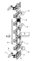
- FIG. 1 is an overall schematic diagram of Embodiment 1.
- a frame member setting step for setting the honeycomb structure 1 to the frame member 2, a masking film 6 on the end surface 4 of the honeycomb structure 1 and the outer surface 5 of the frame member 2.
- a masking film affixing step for forming a slurry filling hole by irradiating a laser beam on the masking film 6 at a position covering the open end of the cell to be sealed, and a honeycomb It has the sealing process which fills the edge part of the structure 1 with a slurry, and the masking film peeling process which peels the masking film 6 from the honeycomb structure 1 and the frame member 2 which passed through the sealing process.
- each process is explained in full detail.
- the honeycomb structure 1 composed of a plurality of cells is fitted into the frame member 2 with the end portions thereof being horizontal with the cell longitudinal direction being horizontal.
- the frame member 2 has a central opening 3 having substantially the same shape as the cross-sectional shape of the honeycomb structure 1.
- the honeycomb structure 1 fitted into the frame member 2 is aligned so that the end surface 4 and the outer surface 5 of the frame member 2 are on substantially the same plane.
- the honeycomb structure 1 of the present embodiment is a SiC honeycomb structure used for SiC-DPF (SiC diesel particulate filter), and a kneaded material kneaded with a forming raw material according to a conventional general method. It was produced by forming into a honeycomb shape and drying.
- SiC-DPF SiC diesel particulate filter
- the frame member 2 and the honeycomb structure 1 set in the frame member setting step are intermittently conveyed to the masking film sticking step while maintaining the cell longitudinal direction horizontally.
- the roll-shaped masking film 6 having one side as an adhesive surface is continuously unwound and arranged on the outer surface side 5 of the frame member 2. After that, the sheet is pressed by the pressing means 7 and attached to both the end surface 4 of the honeycomb structure 1 and the outer surface 5 of the frame member 2.
- both the end surface 4 of the honeycomb structure 1 and the outer surface 5 of the frame member 2 are simultaneously masked without using a complicated additional device.
- the film 6 can be covered, and then the deviation between them can be avoided.
- the roll-shaped masking film 6 was continuously unwound without being cut and aligned in the above step. Since 4 stickers are attached to the end surface of the honeycomb structure 1 from the outer surface 5 side of the frame member 2, the masking film cutting work and the folding work are completely unnecessary, and the work efficiency of the masking film sticking work is improved. Can be improved.
- the material of the masking film 6 is not particularly limited, but in consideration of thermal processability when forming a slurry filling hole described later, polypropylene (PP), polyethylene terephthalate (PET), polyimide, or fluororesin may be used. preferable.
- the honeycomb structure 1 and the frame member 2 to which the masking film 6 is attached are intermittently conveyed to the slurry filling hole forming step while keeping the cell longitudinal direction horizontal.
- the end face of the honeycomb structure is imaged and the positions of all the cells are recognized by performing image processing on the image of the picked end face, as in the conventional method, and then on the masking film 6
- the slurry filling hole is formed by irradiating the laser beam to the position covering the open end of the cell to be sealed.
- the honeycomb structure 1 and the frame member 2 to which the masking film 6 in which the slurry filling holes are formed are affixed intermittently to the sealing step while maintaining the cell longitudinal direction horizontally.
- a method of immersing the end of the honeycomb structure in a container in which the slurry 11 is stored is generally employed.
- the honeycomb structure 1 and the frame member 2 that have undergone the sealing process are intermittently conveyed to the masking film peeling process while holding the masking film 6 and holding the cell longitudinal direction horizontal.
- the masking film 6 is used while being fed by a so-called “roll-to-roll method”, and the masking film 6 unwound from the roll shape in the masking film application step is rolled again in this step. It is wound up in a shape.
- the end surface 4 of the honeycomb structure 1 and the frame member 2 are brought together with the winding operation of the masking film 6. Since the masking film 6 affixed to the outer surface 5 can be peeled continuously, there is no need to peel off the film or remove the slurry adhering to the side edge for each product, and the production line and process Can be easy. In addition, since the film is surely peeled along with the winding, it is possible to save the trouble of manually peeling the film remaining due to the incomplete peeling, and the productivity can be improved.
- the drying efficiency can be improved as compared with the case where the drying is performed with the film attached.
- a slurry removing step for removing excess slurry adhering to the surface of the masking film can also be provided.
- the scraping plate 8 is used to scrape off the excess slurry adhering to the surface of the masking film 6, but not particularly limited thereto, for example, brushing off with a brush, A mechanism of wiping off with a roll can also be used.
- a surface drying step for drying the surface layer portion of the slurry filled in the opening end of the cell can be provided prior to the masking film peeling step.
- the honeycomb structure 1 and the frame member 2 that have undergone the slurry removal process are intermittently conveyed to the surface drying process while the masking film 6 is still attached.
- a drying means is not specifically limited, For example, a hot air, a heater, etc. can be used.
Landscapes
- Chemical & Material Sciences (AREA)
- Engineering & Computer Science (AREA)
- Ceramic Engineering (AREA)
- Structural Engineering (AREA)
- Materials Engineering (AREA)
- Organic Chemistry (AREA)
- Mechanical Engineering (AREA)
- Filtering Materials (AREA)
- Devices For Post-Treatments, Processing, Supply, Discharge, And Other Processes (AREA)
Abstract
DPFの全製造工程のうち、ハニカム構造体の目封じ工程を簡易化し、生産性の向上を図る技術を提供すること。 ロール状のマスキングフィルムを切断することなく連続的に巻出しながら、ハニカム構造体の端部表面をマスキングするマスキング工程と、マスキングフィルム上で、封止すべきセルの開口端部を覆っている箇所に、スラリー充填孔を形成するスラリー充填孔形成工程と、スラリー充填孔からスラリーを充填させる封止工程と、ハニカム構造体の端部表面に貼付されたマスキングフィルムを、切断することなく再度ロール状に巻き取りながら、剥離させるマスキングフィルム剥離工程を有する。
Description
本発明は、ハニカム構造体の目封止方法およびハニカム構造体の目封止装置に関するものである。
ディーゼルエンジンの排気ガス中の粒子状物質を除去するために使用されるDPF(ディーゼル・パティキュレート・フィルタ)は、ハニカム構造体の両端面でセルが交互に封止された構造からなる。その封止方法として、例えば、特許文献1には、ハニカム構造体の端面に、ハニカム構造体の端面にほぼ同一形状のマスキングフィルムを貼り付け、このフィルム上で、封止すべきセルの開口端部を覆っている箇所に封止用のスラリー充填孔を形成し、その後、スラリーが貯留された容器にハニカム構造体の端部を浸漬することにより、所定のセルの開口端部にスラリーを充填させて乾燥させる技術が開示されている。
DPFは、セルの開口端部に充填させたスラリーを乾燥させた後に、焼成工程を経て製造されるが、従来技術では、スラリーの乾燥後、一つ一つの製品についてフィルム表面やハニカム構造体の側端部に付着しているスラリーを除去する工程や、フィルム剥離を行う工程が必要となり、製造ラインや製造プロセスが複雑であるという問題があった。
また、上記工程を経ても完全にフィルムが剥がれないケースもあり、その場合には、手作業によるフィルム剥しが必要となり生産性が悪いという問題や、フィルムサイズがハニカム構造体の端面よりも大きい場合には、余剰部分をハニカム構造体の側面に折り込む作業に手間がかかるという問題の他、スラリーの乾燥後にフィルム剥離を行う上記の従来技術では、フィルムを貼ったまま乾燥が行われるため、乾燥効率が悪いという欠点もあった。
本発明の目的は前記の問題を解決し、DPFの全製造工程のうち、ハニカム構造体の目封止工程を簡易化し、生産性の向上を図る技術を提供することである。
上記課題を解決するためになされた本発明のハニカム構造体の目封止方法は、複数のセルから構成されたハニカム構造体を、セル長手方向を水平に保持して搬送しながら、セルの開口端部にスラリーを充填して封止するハニカム構造体の目封止方法であって、ロール状のマスキングフィルムを切断することなく、上記ハニカム構造体と同期させて連続的に巻出しながら、ハニカム構造体の端部表面をマスキングするマスキング工程と、マスキングフィルム上で、封止すべきセルの開口端部を覆っている箇所に、スラリー充填孔を形成するスラリー充填孔形成工程と、スラリー充填孔からスラリーを充填させる封止工程と、ハニカム構造体の端部表面に貼付されたマスキングフィルムを、切断することなく再度ロール状に巻き取りながら、剥離させるマスキングフィルム剥離工程とを有することを特徴とするものである。
請求項2記載の発明は、請求項1記載のハニカム構造体の目封止方法において、前記マスキング工程に先立って、ハニカム構造体の端部を、該ハニカム構造体の断面形状と略同一形状の中央開口部を有する枠部材に嵌め込んで、ハニカム構造体の端部表面と枠部材の外表面とを位置合わせする枠部材セット工程を有し、前記マスキング工程では、片側面を粘着面とするロール状のマスキングフィルムを巻出しながら、前記枠部材セット工程で位置合わせされた枠部材の外表面側から、ハニカム構造体の端部表面に貼付することを特徴とするものである。
請求項3記載の発明は、請求項1または2記載のハニカム構造体の目封止方法において、スラリー充填孔形成工程では、ハニカム構造体の端面を撮像し、撮像した端面の画像を画像処理することにより全セルの位置を認識した後、マスキングフィルム上で、目封止すべきセルの開口端部を覆っている位置にレーザー光を照射してスラリー充填孔を形成することを特徴とするものである。
請求項4記載の発明は、請求項1~3の何れかに記載のハニカム構造体の目封止方法において、前記マスキングフィルム剥離工程に先立って、マスキングフィルムの表面に付着した余剰のスラリーを除去するスラリー除去工程を有することを特徴とするものである。
請求項5記載の発明は、請求項4記載のハニカム構造体の目封止方法において、前記スラリー除去工程のあと、前記マスキングフィルム剥離工程に先立って、セルの開口部端に充填されたスラリーの表層部を乾燥する表面乾燥工程を有することを特徴とするものである。
請求項6記載の発明は、請求項1~5の何れかに記載のハニカム構造体の目封止方法において、ハニカム構造体の端面を片側ずつ、もしくは、両端面を同時に目封止することを特徴とするものである。
請求項7記載の発明は、複数のセルから構成されたハニカム構造体を、セル長手方向を水平に保持して搬送しながら、セルの開口端部を封止するハニカム構造体の目封止装置であって、ハニカム構造体の断面形状と略同一形状の中央開口部を有する枠部材と、ロール状のマスキングフィルムを切断することなく連続的に巻出しながら、該枠部材に嵌め込まれたハニカム構造体の端部表面に貼付するマスキングフィルム貼付手段と、マスキングフィルム上で、封止すべきセルの開口端部を覆っている箇所に、スラリー充填孔を形成するスラリー充填孔形成手段と、スラリー充填孔からスラリーを充填させる封止手段と、ハニカム構造体の端部表面に貼付されたマスキングフィルムを、切断することなく連続的に巻き取りながら、剥離させるマスキングフィルム剥離手段を有することを特徴とするものである。
請求項8に記載の発明は、請求項7記載のハニカム構造体の目封止装置において、前記マスキングフィルムの剥離に先立って、マスキングフィルムの表面に付着した余剰のスラリーを除去するスラリー除去手段を有することを特徴とするものである。
請求項9に記載の発明は、請求項8記載のハニカム構造体の目封止装置において、前記スラリー除去の後、スラリー表面を乾燥する表面乾燥手段を有することを特徴とするものである。
ロール状のマスキングフィルムを切断することなく、上記ハニカム構造体と同期させて連続的に巻出しながら、ハニカム構造体の端部表面のマスキングを行い、続くスラリー充填孔形成と目封止の後、ハニカム構造体の端部表面に貼付されたマスキングフィルムを、切断することなく再度ロール状に巻き取りながら剥離させる本発明によれば、巻き取りに伴ってフィルムの剥離を連続的に簡単に行うことができ、製品一つごとにフィルムの剥離や側端部に付着したスラリーの除去を行う必要がなくなるため、製造ラインや製造プロセスを簡単にすることができ、また巻き取りに伴って確実にフィルムの剥離が行われるため、手作業でフィルムの剥離を行う必要もなくなり、生産性を向上することができる。
また、従来技術では、ハニカム構造体の端面をほぼ同一形状のマスキングフィルムを用いてマスキングを行い、マスキングフィルムサイズがハニカム構造体の端面よりも大きい場合には、余剰部分をハニカム構造体の側面に折り込む作業を行っていたため、マスキングフィルム貼付作業やマスキングフィルム剥離作業に手間と時間がかかっていたのに対し、本発明では、ロール状のマスキングフィルムを切断することなく連続的に巻出してマスキング用途に使用し、使用後にはそのまま巻き取りを行うことにより、フィルム貼付作業に伴う折り込み作業を省略できるとともに、フィルムの巻き取り作業に伴ってフィルム剥離作業を簡単に行うことができ、フィルム貼付作業やフィルム剥離作業の作業性を改善することができる。
その他、本発明では、スラリーの乾燥工程に先立って、フィルム剥離を行うため、従来、フィルムを貼ったまま乾燥を行っていた場合と比べて、乾燥効率も改善することができる。
以下に本発明の好ましい実施形態を示す。
(実施形態1)
実施形態1は、図1に示すように、ハニカム構造体1を枠部材2にセットする枠部材セット工程と、ハニカム構造体1の端部表面4と枠部材2の外表面5にマスキングフィルム6を貼付するマスキングフィルム貼付工程と、マスキングフィルム6上で、封止すべきセルの開口端部を覆っている位置にレーザー光を照射してスラリー充填孔を形成するスラリー充填孔形成工程と、ハニカム構造体1の端部にスラリーを充填する封止工程と、封止工程を経たハニカム構造体1と枠部材2からマスキングフィルム6を剥離するマスキングフィルム剥離工程を有している。以下、各工程について詳述する。
実施形態1は、図1に示すように、ハニカム構造体1を枠部材2にセットする枠部材セット工程と、ハニカム構造体1の端部表面4と枠部材2の外表面5にマスキングフィルム6を貼付するマスキングフィルム貼付工程と、マスキングフィルム6上で、封止すべきセルの開口端部を覆っている位置にレーザー光を照射してスラリー充填孔を形成するスラリー充填孔形成工程と、ハニカム構造体1の端部にスラリーを充填する封止工程と、封止工程を経たハニカム構造体1と枠部材2からマスキングフィルム6を剥離するマスキングフィルム剥離工程を有している。以下、各工程について詳述する。
(枠部材セット工程)
図1に示すように、複数のセルから構成されたハニカム構造体1は、セル長手方向を水平にして、その端部が枠部材2に嵌め込まれる。枠部材2は、ハニカム構造体1の断面形状と略同一形状の中央開口部3を有している。枠部材2に嵌め込まれたハニカム構造体1は、その端部表面4と、枠部材2の外表面5とが、略同一平面上にくるように、位置合わせが行われる。
図1に示すように、複数のセルから構成されたハニカム構造体1は、セル長手方向を水平にして、その端部が枠部材2に嵌め込まれる。枠部材2は、ハニカム構造体1の断面形状と略同一形状の中央開口部3を有している。枠部材2に嵌め込まれたハニカム構造体1は、その端部表面4と、枠部材2の外表面5とが、略同一平面上にくるように、位置合わせが行われる。
本実施形態のハニカム構造体1は、SiC-DPF(SiC製のディーゼルパティキュレートフィルタ)に使用されるSiC製のハニカム構造体であり、従来一般の手法にしたがって、成形原料を混練した坏土をハニカム形状に成形および乾燥して作製されたものである。
(マスキングフィルム貼付工程)
枠部材セット工程でセットされた枠部材2とハニカム構造体1は、セル長手方向を水平に保持しながら、マスキングフィルム貼付工程に間欠搬送される。
枠部材セット工程でセットされた枠部材2とハニカム構造体1は、セル長手方向を水平に保持しながら、マスキングフィルム貼付工程に間欠搬送される。
マスキングフィルム貼付工程では、図1に示すように、片側面を粘着面とするロール状のマスキングフィルム6を、切断することなく連続的に巻出して、枠部材2の外表面側5に配置した後、押し付け手段7で押し付け、ハニカム構造体1の端部表面4と枠部材2の外表面5の双方に貼付する。
このように、片側面を粘着面とするマスキングフィルム6を用いることにより、複雑な追加装置を用いることなく、ハニカム構造体1の端部表面4と枠部材2の外表面5の双方を同時にマスキングフィルム6で被覆することができ、その後、両者のズレも回避することができる。
また、従来技術のように、ハニカム構造体の端面に、ハニカム構造体の端面をほぼ同一形状のマスキングフィルムを貼り付ける場合には、フィルムサイズがハニカム構造体の端面よりも大きい場合には、余剰部分をハニカム構造体の側面に折り込む作業に手間がかかるという問題があったが、本発明では、ロール状のマスキングフィルム6を切断することなく連続的に巻出しながら、前記工程で位置合わせされた枠部材2の外表面5側から、ハニカム構造体1の端部表面に4貼付していくため、マスキングフィルムの切断作業や、折り込み作業が完全に不要となり、マスキングフィルム貼付作業の作業効率を各段に向上させることができる。
マスキングフィルム6の材料は、特に制限はないが、後述のスラリー充填孔を形成する際の、熱加工性を考慮すると、ポリプロピレン(PP)、ポリエチレンテレフタレート(PET)、ポリイミド、フッ素樹脂を用いることが好ましい。
(スラリー充填孔形成工程)
マスキングフィルム6が貼付されたハニカム構造体1と枠部材2は、セル長手方向を水平に保持しながら、スラリー充填孔形成工程に間欠搬送される。
マスキングフィルム6が貼付されたハニカム構造体1と枠部材2は、セル長手方向を水平に保持しながら、スラリー充填孔形成工程に間欠搬送される。
本実施形態のスラリー充填孔形成工程では、従来手法と同様に、ハニカム構造体の端面を撮像し、撮像した端面の画像を画像処理することにより全セルの位置を認識した後、マスキングフィルム6上で、封止すべきセルの開口端部を覆っている位置にレーザー光を照射してスラリー充填孔が形成される。
(封止工程)
スラリー充填孔が形成されたマスキングフィルム6を貼付したハニカム構造体1と枠部材2は、セル長手方向を水平に保持しながら、封止工程に間欠搬送される。
スラリー充填孔が形成されたマスキングフィルム6を貼付したハニカム構造体1と枠部材2は、セル長手方向を水平に保持しながら、封止工程に間欠搬送される。
封止工程では、スラリー11が貯留された容器にハニカム構造体の端部を浸漬する手法が一般に採用されている。
(マスキングフィルム剥離工程)
封止工程を経たハニカム構造体1と枠部材2は、マスキングフィルム6を貼付したままで、セル長手方向を水平に保持しながら、マスキングフィルム剥離工程に間欠搬送される。
封止工程を経たハニカム構造体1と枠部材2は、マスキングフィルム6を貼付したままで、セル長手方向を水平に保持しながら、マスキングフィルム剥離工程に間欠搬送される。
本発明では、マスキングフィルム6を、いわゆる「ロール・トゥ・ロール方式」で送りながら使用しており、前記のマスキングフィルム貼付工程でロール状から巻き出されたマスキングフィルム6を、本工程で再度ロール状に巻き取っている。
このように、マスキングフィルム6を、「ロール・トゥ・ロール方式」で送りながら使用することにより、マスキングフィルム6の巻き取り動作に伴って、ハニカム構造体1の端部表面4と枠部材2の外表面5に貼付されたマスキングフィルム6を連続的に剥離することができるため、製品一つごとにフィルムの剥離や側端部に付着したスラリーの除去を行う必要がなくなり、製造ラインや製造プロセスを簡単にすることができる。また巻き取りに伴って確実にフィルムの剥離が行われるため、不完全な剥離により残存したフィルムを再度、手作業で剥離する手間を省くことができ、生産性を向上することができる。
更に、本発明では、スラリーの乾燥工程に先立って、フィルム剥離を行うため、従来、フィルムを貼ったまま乾燥を行っていた場合と比べて、乾燥効率も改善することができる。
(実施形態2)
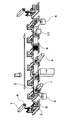
図2に示すように、マスキングフィルム剥離工程に先立って、マスキングフィルムの表面に付着した余剰のスラリーを除去するスラリー除去工程を設けることもできる。
図2に示すように、マスキングフィルム剥離工程に先立って、マスキングフィルムの表面に付着した余剰のスラリーを除去するスラリー除去工程を設けることもできる。
(スラリー除去工程)
本実施形態では、図2に示すように、封止工程を経たハニカム構造体1と枠部材2は、マスキングフィルム6を貼付したままで、スラリー除去工程に間欠搬送される。
本実施形態では、図2に示すように、封止工程を経たハニカム構造体1と枠部材2は、マスキングフィルム6を貼付したままで、スラリー除去工程に間欠搬送される。
本実施形態のスラリー除去工程では、かきとり板8を使用して、マスキングフィルム6の表面に付着した余剰のスラリーを掻き落としているが、特にそれに限定されることなく、例えばブラシで払い落としたり、ロールで拭い落としたりする機構を用いることもできる。
このように、マスキングフィルムの剥離に先立って余剰のスラリーを除去しておくことにより、マスキングフィルムを剥離する際にセルの開口部端に充填されたスラリーの一部がマスキングフィルムに取られることを防ぐことができ、また、マスキングフィルムをロール上に巻き取る際に巻き取りが不安定になることを防ぐことができる。
(実施形態3)
図3に示すように、前記スラリー除去工程のあと、前記マスキングフィルム剥離工程に先立って、セルの開口部端に充填されたスラリーの表層部を乾燥する表面乾燥工程を設けることもできる。
図3に示すように、前記スラリー除去工程のあと、前記マスキングフィルム剥離工程に先立って、セルの開口部端に充填されたスラリーの表層部を乾燥する表面乾燥工程を設けることもできる。
(表面乾燥工程)
本実施形態では、図3に示すように、スラリー除去工程を経たハニカム構造体1と枠部材2は、マスキングフィルム6を貼付したままで、表面乾燥工程に間欠搬送される。
本実施形態では、図3に示すように、スラリー除去工程を経たハニカム構造体1と枠部材2は、マスキングフィルム6を貼付したままで、表面乾燥工程に間欠搬送される。
表面乾燥工程では、セルの開口部端に充填させたスラリーの表層部を乾燥すればよく、セルの開口部端に充填されたスラリー全体を乾燥させる必要は特にない。乾燥手段は特に限定されず、例えば、熱風やヒーター等を用いることができる。
このようにセルの開口部端に充填させたスラリーの表層部を乾燥することにより、スラリーの全体を乾燥する工程の前にマスキングフィルムを剥離した場合に発生するおそれのあるスラリー全体を乾燥した後のセルの開口部端表面におけるスラリー収縮の程度を軽減することができる。
1 ハニカム構造体
2 枠部材
3 中央開口部
4 端部表面
5 外表面
6 マスキングフィルム
7 押し付け手段
8 かきとり板
9 スラリー充填手段
10 表面乾燥装置
2 枠部材
3 中央開口部
4 端部表面
5 外表面
6 マスキングフィルム
7 押し付け手段
8 かきとり板
9 スラリー充填手段
10 表面乾燥装置
Claims (9)
- 複数のセルから構成されたハニカム構造体を、セル長手方向を水平に保持して搬送しながら、セルの開口端部にスラリーを充填して封止するハニカム構造体の目封止方法であって、ロール状のマスキングフィルムを切断することなく、上記ハニカム構造体と同期させて連続的に巻出しながら、ハニカム構造体の端部表面をマスキングするマスキング工程と、マスキングフィルム上で、封止すべきセルの開口端部を覆っている箇所に、スラリー充填孔を形成するスラリー充填孔形成工程と、スラリー充填孔からスラリーを充填させる封止工程と、ハニカム構造体の端部表面に貼付されたマスキングフィルムを、切断することなく再度ロール状に巻き取りながら、剥離させるマスキングフィルム剥離工程とを有することを特徴とするハニカム構造体の目封止方法。
- 前記マスキング工程に先立って、ハニカム構造体の端部を、該ハニカム構造体の断面形状と略同一形状の中央開口部を有する枠部材に嵌め込んで、ハニカム構造体の端部表面と枠部材の外表面とを位置合わせする枠部材セット工程を有し、前記マスキング工程では、片側面を粘着面とするロール状のマスキングフィルムを巻出しながら、前記枠部材セット工程で位置合わせされた枠部材の外表面側から、ハニカム構造体の端部表面に貼付することを特徴とする請求項1記載のハニカム構造体の目封止方法。
- スラリー充填孔形成工程では、ハニカム構造体の端面を撮像し、撮像した端面の画像を画像処理することにより全セルの位置を認識した後、マスキングフィルム上で、目封止すべきセルの開口端部を覆っている位置にレーザー光を照射してスラリー充填孔を形成することを特徴とする請求項1または2記載のハニカム構造体の目封止方法。
- 前記マスキングフィルム剥離工程に先立って、マスキングフィルムの表面に付着した余剰のスラリーを除去するスラリー除去工程を有することを特徴とする請求項1~3の何れかに記載のハニカム構造体の目封止方法。
- 前記スラリー除去工程のあと、前記マスキングフィルム剥離工程に先立って、セルの開口部端に充填されたスラリーの表層部を乾燥する表面乾燥工程を有することを特徴とする請求項4記載のハニカム構造体の目封止方法。
- ハニカム構造体の端面を片側ずつ、もしくは、両端面を同時に目封止することを特徴とする請求項1~5の何れかに記載のハニカム構造体の目封止方法。
- 複数のセルから構成されたハニカム構造体を、セル長手方向を水平に保持して搬送しながら、セルの開口端部を封止するハニカム構造体の目封止装置であって、ハニカム構造体の断面形状と略同一形状の中央開口部を有する枠部材と、ロール状のマスキングフィルムを切断することなく連続的に巻出しながら、該枠部材に嵌め込まれたハニカム構造体の端部表面に貼付するマスキングフィルム貼付手段と、マスキングフィルム上で、封止すべきセルの開口端部を覆っている箇所に、スラリー充填孔を形成するスラリー充填孔形成手段と、スラリー充填孔からスラリーを充填させる封止手段と、ハニカム構造体の端部表面に貼付されたマスキングフィルムを、切断することなく連続的に巻き取りながら、剥離させるマスキングフィルム剥離手段を有することを特徴とするハニカム構造体の目封止装置。
- 前記マスキングフィルムの剥離に先立って、マスキングフィルムの表面に付着した余剰のスラリーを除去するスラリー除去手段を有することを特徴とする請求項7記載のハニカム構造体の目封止装置。
- 前記スラリー除去の後、スラリー表面を乾燥する表面乾燥手段を有することを特徴とする請求項8記載のハニカム構造体の目封止装置。
Priority Applications (2)
| Application Number | Priority Date | Filing Date | Title |
|---|---|---|---|
| JP2015506787A JPWO2014148460A1 (ja) | 2013-03-21 | 2014-03-18 | ハニカム構造体の目封止方法およびハニカム構造体の目封止装置 |
| EP14768695.0A EP2977162A4 (en) | 2013-03-21 | 2014-03-18 | Sealing method for honeycomb structural body, and sealing device for honeycomb structural body |
Applications Claiming Priority (2)
| Application Number | Priority Date | Filing Date | Title |
|---|---|---|---|
| JP2013058203 | 2013-03-21 | ||
| JP2013-058203 | 2013-03-21 |
Publications (1)
| Publication Number | Publication Date |
|---|---|
| WO2014148460A1 true WO2014148460A1 (ja) | 2014-09-25 |
Family
ID=51580139
Family Applications (1)
| Application Number | Title | Priority Date | Filing Date |
|---|---|---|---|
| PCT/JP2014/057235 Ceased WO2014148460A1 (ja) | 2013-03-21 | 2014-03-18 | ハニカム構造体の目封止方法およびハニカム構造体の目封止装置 |
Country Status (3)
| Country | Link |
|---|---|
| EP (1) | EP2977162A4 (ja) |
| JP (1) | JPWO2014148460A1 (ja) |
| WO (1) | WO2014148460A1 (ja) |
Cited By (2)
| Publication number | Priority date | Publication date | Assignee | Title |
|---|---|---|---|---|
| JP2015178436A (ja) * | 2014-03-19 | 2015-10-08 | 日本碍子株式会社 | 目封止ハニカム構造体の製造方法、及び目封止部形成装置 |
| JP2019521021A (ja) * | 2016-07-13 | 2019-07-25 | コーニング インコーポレイテッド | セラミックハニカム体を施栓するためのシステムおよび方法 |
Citations (4)
| Publication number | Priority date | Publication date | Assignee | Title |
|---|---|---|---|---|
| JP2002126421A (ja) * | 2000-10-31 | 2002-05-08 | Ibiden Co Ltd | 接着シートの剥離方法及び剥離装置 |
| JP3715174B2 (ja) | 2000-04-18 | 2005-11-09 | 日本碍子株式会社 | セラミック体の製造方法 |
| WO2009011435A1 (ja) * | 2007-07-18 | 2009-01-22 | Ngk Insulators, Ltd. | ハニカム構造体の製造方法、及びその製造装置 |
| JP2010105324A (ja) * | 2008-10-31 | 2010-05-13 | Ngk Insulators Ltd | フィルム貼付装置及びフィルム貼付け方法 |
Family Cites Families (1)
| Publication number | Priority date | Publication date | Assignee | Title |
|---|---|---|---|---|
| JP5331635B2 (ja) * | 2009-09-28 | 2013-10-30 | 日本碍子株式会社 | 目封止ハニカム構造体の製造方法 |
-
2014
- 2014-03-18 WO PCT/JP2014/057235 patent/WO2014148460A1/ja not_active Ceased
- 2014-03-18 EP EP14768695.0A patent/EP2977162A4/en not_active Withdrawn
- 2014-03-18 JP JP2015506787A patent/JPWO2014148460A1/ja active Pending
Patent Citations (4)
| Publication number | Priority date | Publication date | Assignee | Title |
|---|---|---|---|---|
| JP3715174B2 (ja) | 2000-04-18 | 2005-11-09 | 日本碍子株式会社 | セラミック体の製造方法 |
| JP2002126421A (ja) * | 2000-10-31 | 2002-05-08 | Ibiden Co Ltd | 接着シートの剥離方法及び剥離装置 |
| WO2009011435A1 (ja) * | 2007-07-18 | 2009-01-22 | Ngk Insulators, Ltd. | ハニカム構造体の製造方法、及びその製造装置 |
| JP2010105324A (ja) * | 2008-10-31 | 2010-05-13 | Ngk Insulators Ltd | フィルム貼付装置及びフィルム貼付け方法 |
Non-Patent Citations (1)
| Title |
|---|
| See also references of EP2977162A4 * |
Cited By (3)
| Publication number | Priority date | Publication date | Assignee | Title |
|---|---|---|---|---|
| JP2015178436A (ja) * | 2014-03-19 | 2015-10-08 | 日本碍子株式会社 | 目封止ハニカム構造体の製造方法、及び目封止部形成装置 |
| JP2019521021A (ja) * | 2016-07-13 | 2019-07-25 | コーニング インコーポレイテッド | セラミックハニカム体を施栓するためのシステムおよび方法 |
| US11472061B2 (en) | 2016-07-13 | 2022-10-18 | Corning Incorporated | System and methods of plugging ceramic honeycomb bodies |
Also Published As
| Publication number | Publication date |
|---|---|
| EP2977162A1 (en) | 2016-01-27 |
| EP2977162A4 (en) | 2017-03-15 |
| JPWO2014148460A1 (ja) | 2017-02-16 |
Similar Documents
| Publication | Publication Date | Title |
|---|---|---|
| JP6103220B2 (ja) | マーキング装置、検査装置、及び電極製造方法 | |
| CN101754838B (zh) | 蜂窝状构造体的制造方法及其制造装置 | |
| CN110328216A (zh) | 一种光伏组件回收方法 | |
| JP2010514102A5 (ja) | ||
| JP2010119967A (ja) | 触媒回収方法、装置及びこれを備えた膜−電極接合体製造設備 | |
| WO2014148460A1 (ja) | ハニカム構造体の目封止方法およびハニカム構造体の目封止装置 | |
| CN104369525A (zh) | 从膜层叠体去除异物的异物去除方法、膜层叠体的制造方法及制造装置 | |
| CN202130098U (zh) | 具有剥离功能的涂布复合机 | |
| ITTO980779A1 (it) | Componente per circuito stampato multistrato, metodo per la sua fabbri cazione e relativo circuito stampato multiuso. | |
| CN106283927A (zh) | 一种镭射介质转移平张纸的生产工艺 | |
| CN106611879A (zh) | 卷绕体 | |
| JP6210001B2 (ja) | ロールプレス装置 | |
| CN106953057A (zh) | 功能性膜的制造方法以及功能性膜的制造装置 | |
| JP2015210923A (ja) | 電極材料の検査装置及び電極材料の検査方法 | |
| CN104540682B (zh) | 版印刷方法 | |
| CN106315561A (zh) | 一种石墨烯薄膜的大面积无损转移方法和石墨烯‑目标衬底的复合体 | |
| WO2013187368A1 (ja) | 塗工膜の剥離装置、二次電池用セパレータの製造装置、塗工膜の剥離方法、及び、二次電池用セパレータの製造方法 | |
| JP2010146796A (ja) | 燃料電池用の膜−電極接合体の製造方法及びその製造装置 | |
| CN106953048B (zh) | 膜制造方法 | |
| JP6811537B2 (ja) | エキスパンダ装置、多孔質フィルム製造装置、及び多孔質フィルム製造方法 | |
| WO2016059693A1 (ja) | 電極シートの製造装置及び製造方法 | |
| KR102016509B1 (ko) | 이차전지 전극 제조 방법 | |
| JP6388325B2 (ja) | シートの接続方法 | |
| JP2010149039A (ja) | フィルム基板の洗浄装置及び洗浄方法 | |
| JP5529067B2 (ja) | 膜電極接合体の製造方法、及び膜電極接合体製造装置 |
Legal Events
| Date | Code | Title | Description |
|---|---|---|---|
| 121 | Ep: the epo has been informed by wipo that ep was designated in this application |
Ref document number: 14768695 Country of ref document: EP Kind code of ref document: A1 |
|
| ENP | Entry into the national phase |
Ref document number: 2015506787 Country of ref document: JP Kind code of ref document: A |
|
| WWE | Wipo information: entry into national phase |
Ref document number: 2014768695 Country of ref document: EP |
|
| NENP | Non-entry into the national phase |
Ref country code: DE |