WO2014148461A1 - 連続押出成形装置 - Google Patents
連続押出成形装置 Download PDFInfo
- Publication number
- WO2014148461A1 WO2014148461A1 PCT/JP2014/057238 JP2014057238W WO2014148461A1 WO 2014148461 A1 WO2014148461 A1 WO 2014148461A1 JP 2014057238 W JP2014057238 W JP 2014057238W WO 2014148461 A1 WO2014148461 A1 WO 2014148461A1
- Authority
- WO
- WIPO (PCT)
- Prior art keywords
- extrusion
- flow path
- horizontal direction
- extrusion molding
- horizontal
- Prior art date
- Legal status (The legal status is an assumption and is not a legal conclusion. Google has not performed a legal analysis and makes no representation as to the accuracy of the status listed.)
- Ceased
Links
Images


Classifications
-
- B—PERFORMING OPERATIONS; TRANSPORTING
- B29—WORKING OF PLASTICS; WORKING OF SUBSTANCES IN A PLASTIC STATE IN GENERAL
- B29C—SHAPING OR JOINING OF PLASTICS; SHAPING OF MATERIAL IN A PLASTIC STATE, NOT OTHERWISE PROVIDED FOR; AFTER-TREATMENT OF THE SHAPED PRODUCTS, e.g. REPAIRING
- B29C48/00—Extrusion moulding, i.e. expressing the moulding material through a die or nozzle which imparts the desired form; Apparatus therefor
- B29C48/03—Extrusion moulding, i.e. expressing the moulding material through a die or nozzle which imparts the desired form; Apparatus therefor characterised by the shape of the extruded material at extrusion
- B29C48/09—Articles with cross-sections having partially or fully enclosed cavities, e.g. pipes or channels
- B29C48/11—Articles with cross-sections having partially or fully enclosed cavities, e.g. pipes or channels comprising two or more partially or fully enclosed cavities, e.g. honeycomb-shaped
-
- B—PERFORMING OPERATIONS; TRANSPORTING
- B28—WORKING CEMENT, CLAY, OR STONE
- B28B—SHAPING CLAY OR OTHER CERAMIC COMPOSITIONS; SHAPING SLAG; SHAPING MIXTURES CONTAINING CEMENTITIOUS MATERIAL, e.g. PLASTER
- B28B17/00—Details of, or accessories for, apparatus for shaping the material; Auxiliary measures taken in connection with such shaping
- B28B17/009—Changing the forming elements, e.g. exchanging moulds, dies
-
- B—PERFORMING OPERATIONS; TRANSPORTING
- B28—WORKING CEMENT, CLAY, OR STONE
- B28B—SHAPING CLAY OR OTHER CERAMIC COMPOSITIONS; SHAPING SLAG; SHAPING MIXTURES CONTAINING CEMENTITIOUS MATERIAL, e.g. PLASTER
- B28B3/00—Producing shaped articles from the material by using presses; Presses specially adapted therefor
- B28B3/20—Producing shaped articles from the material by using presses; Presses specially adapted therefor wherein the material is extruded
- B28B3/26—Extrusion dies
- B28B3/269—For multi-channeled structures, e.g. honeycomb structures
-
- B—PERFORMING OPERATIONS; TRANSPORTING
- B29—WORKING OF PLASTICS; WORKING OF SUBSTANCES IN A PLASTIC STATE IN GENERAL
- B29C—SHAPING OR JOINING OF PLASTICS; SHAPING OF MATERIAL IN A PLASTIC STATE, NOT OTHERWISE PROVIDED FOR; AFTER-TREATMENT OF THE SHAPED PRODUCTS, e.g. REPAIRING
- B29C48/00—Extrusion moulding, i.e. expressing the moulding material through a die or nozzle which imparts the desired form; Apparatus therefor
- B29C48/025—General arrangement or layout of plant
-
- B—PERFORMING OPERATIONS; TRANSPORTING
- B29—WORKING OF PLASTICS; WORKING OF SUBSTANCES IN A PLASTIC STATE IN GENERAL
- B29C—SHAPING OR JOINING OF PLASTICS; SHAPING OF MATERIAL IN A PLASTIC STATE, NOT OTHERWISE PROVIDED FOR; AFTER-TREATMENT OF THE SHAPED PRODUCTS, e.g. REPAIRING
- B29C48/00—Extrusion moulding, i.e. expressing the moulding material through a die or nozzle which imparts the desired form; Apparatus therefor
- B29C48/25—Component parts, details or accessories; Auxiliary operations
- B29C48/255—Flow control means, e.g. valves
-
- B—PERFORMING OPERATIONS; TRANSPORTING
- B29—WORKING OF PLASTICS; WORKING OF SUBSTANCES IN A PLASTIC STATE IN GENERAL
- B29C—SHAPING OR JOINING OF PLASTICS; SHAPING OF MATERIAL IN A PLASTIC STATE, NOT OTHERWISE PROVIDED FOR; AFTER-TREATMENT OF THE SHAPED PRODUCTS, e.g. REPAIRING
- B29C48/00—Extrusion moulding, i.e. expressing the moulding material through a die or nozzle which imparts the desired form; Apparatus therefor
- B29C48/25—Component parts, details or accessories; Auxiliary operations
- B29C48/255—Flow control means, e.g. valves
- B29C48/2556—Flow control means, e.g. valves provided in or in the proximity of dies
-
- B—PERFORMING OPERATIONS; TRANSPORTING
- B29—WORKING OF PLASTICS; WORKING OF SUBSTANCES IN A PLASTIC STATE IN GENERAL
- B29C—SHAPING OR JOINING OF PLASTICS; SHAPING OF MATERIAL IN A PLASTIC STATE, NOT OTHERWISE PROVIDED FOR; AFTER-TREATMENT OF THE SHAPED PRODUCTS, e.g. REPAIRING
- B29C48/00—Extrusion moulding, i.e. expressing the moulding material through a die or nozzle which imparts the desired form; Apparatus therefor
- B29C48/25—Component parts, details or accessories; Auxiliary operations
- B29C48/256—Exchangeable extruder parts
- B29C48/2562—Mounting or handling of the die
-
- B—PERFORMING OPERATIONS; TRANSPORTING
- B29—WORKING OF PLASTICS; WORKING OF SUBSTANCES IN A PLASTIC STATE IN GENERAL
- B29C—SHAPING OR JOINING OF PLASTICS; SHAPING OF MATERIAL IN A PLASTIC STATE, NOT OTHERWISE PROVIDED FOR; AFTER-TREATMENT OF THE SHAPED PRODUCTS, e.g. REPAIRING
- B29C48/00—Extrusion moulding, i.e. expressing the moulding material through a die or nozzle which imparts the desired form; Apparatus therefor
- B29C48/25—Component parts, details or accessories; Auxiliary operations
- B29C48/256—Exchangeable extruder parts
- B29C48/2566—Die parts
-
- B—PERFORMING OPERATIONS; TRANSPORTING
- B29—WORKING OF PLASTICS; WORKING OF SUBSTANCES IN A PLASTIC STATE IN GENERAL
- B29C—SHAPING OR JOINING OF PLASTICS; SHAPING OF MATERIAL IN A PLASTIC STATE, NOT OTHERWISE PROVIDED FOR; AFTER-TREATMENT OF THE SHAPED PRODUCTS, e.g. REPAIRING
- B29C48/00—Extrusion moulding, i.e. expressing the moulding material through a die or nozzle which imparts the desired form; Apparatus therefor
- B29C48/25—Component parts, details or accessories; Auxiliary operations
- B29C48/27—Cleaning; Purging; Avoiding contamination
- B29C48/272—Cleaning; Purging; Avoiding contamination of dies
-
- B—PERFORMING OPERATIONS; TRANSPORTING
- B29—WORKING OF PLASTICS; WORKING OF SUBSTANCES IN A PLASTIC STATE IN GENERAL
- B29C—SHAPING OR JOINING OF PLASTICS; SHAPING OF MATERIAL IN A PLASTIC STATE, NOT OTHERWISE PROVIDED FOR; AFTER-TREATMENT OF THE SHAPED PRODUCTS, e.g. REPAIRING
- B29C48/00—Extrusion moulding, i.e. expressing the moulding material through a die or nozzle which imparts the desired form; Apparatus therefor
- B29C48/25—Component parts, details or accessories; Auxiliary operations
- B29C48/30—Extrusion nozzles or dies
- B29C48/301—Extrusion nozzles or dies having reciprocating, oscillating or rotating parts
-
- B—PERFORMING OPERATIONS; TRANSPORTING
- B29—WORKING OF PLASTICS; WORKING OF SUBSTANCES IN A PLASTIC STATE IN GENERAL
- B29C—SHAPING OR JOINING OF PLASTICS; SHAPING OF MATERIAL IN A PLASTIC STATE, NOT OTHERWISE PROVIDED FOR; AFTER-TREATMENT OF THE SHAPED PRODUCTS, e.g. REPAIRING
- B29C48/00—Extrusion moulding, i.e. expressing the moulding material through a die or nozzle which imparts the desired form; Apparatus therefor
- B29C48/25—Component parts, details or accessories; Auxiliary operations
- B29C48/30—Extrusion nozzles or dies
- B29C48/303—Extrusion nozzles or dies using dies or die parts movable in a closed circuit, e.g. mounted on movable endless support
-
- B—PERFORMING OPERATIONS; TRANSPORTING
- B29—WORKING OF PLASTICS; WORKING OF SUBSTANCES IN A PLASTIC STATE IN GENERAL
- B29C—SHAPING OR JOINING OF PLASTICS; SHAPING OF MATERIAL IN A PLASTIC STATE, NOT OTHERWISE PROVIDED FOR; AFTER-TREATMENT OF THE SHAPED PRODUCTS, e.g. REPAIRING
- B29C48/00—Extrusion moulding, i.e. expressing the moulding material through a die or nozzle which imparts the desired form; Apparatus therefor
- B29C48/25—Component parts, details or accessories; Auxiliary operations
- B29C48/30—Extrusion nozzles or dies
- B29C48/32—Extrusion nozzles or dies with annular openings, e.g. for forming tubular articles
- B29C48/34—Cross-head annular extrusion nozzles, i.e. for simultaneously receiving moulding material and the preform to be coated
-
- B—PERFORMING OPERATIONS; TRANSPORTING
- B29—WORKING OF PLASTICS; WORKING OF SUBSTANCES IN A PLASTIC STATE IN GENERAL
- B29C—SHAPING OR JOINING OF PLASTICS; SHAPING OF MATERIAL IN A PLASTIC STATE, NOT OTHERWISE PROVIDED FOR; AFTER-TREATMENT OF THE SHAPED PRODUCTS, e.g. REPAIRING
- B29C48/00—Extrusion moulding, i.e. expressing the moulding material through a die or nozzle which imparts the desired form; Apparatus therefor
- B29C48/25—Component parts, details or accessories; Auxiliary operations
- B29C48/36—Means for plasticising or homogenising the moulding material or forcing it through the nozzle or die
- B29C48/395—Means for plasticising or homogenising the moulding material or forcing it through the nozzle or die using screws surrounded by a cooperating barrel, e.g. single screw extruders
Definitions
- the present invention relates to a continuous extrusion molding apparatus.
- a method of continuously extruding a honeycomb structure using a continuous extrusion apparatus for example, Patent Document 1 or an extrusion apparatus called a “ram type” is used.
- the method is known.
- the raw material is continuously fed into the drum, the twin-screw installed in the drum is rotated, the raw material is kneaded in the drum, and conveyed to the end of the drum.
- the molding material can be continuously extruded from the provided base
- the method using the “ram type” extrusion molding apparatus the molding material previously kneaded is put into a cylinder and pressurized by a piston.
- the piston is pushed all the way to the stroke end of the cylinder, it is necessary to again feed the molding material into the cylinder, and the joint of the molding material cannot be used as a product, resulting in a material loss.
- the existing continuous extrusion molding apparatus exclusively conveys the forming raw material in the horizontal direction while kneading the forming raw material with the biaxial screw arranged horizontally.
- a “ram type” extrusion apparatus is used.
- a “ram type” extrusion molding apparatus is used in the manufacture of a structure that deforms due to its own weight when extruded in the horizontal direction (for example, a honeycomb structure having a large diameter).
- the larger the size the smaller the quantity that can be produced with one molding material input, and the more the number of molding material inputs.
- the influence of the above-mentioned “raw material loss at the seam of the forming raw material” on the production efficiency increases, which is not preferable.
- the object of the present invention is to solve the above-mentioned problems, and to extrude a structure that deforms due to its own weight when it is extruded in the horizontal direction without being deformed, and to avoid the occurrence of raw material loss accompanying the extrusion. Is to provide technology that can
- the continuous extrusion molding apparatus of the present invention made to solve the above-mentioned problems is a continuous extrusion molding apparatus that incorporates a screw for conveying a molding raw material in the horizontal direction and includes a die part for extrusion molding on the downstream side of the screw part.
- the base part includes a horizontal flow path for horizontally extruding the forming raw material flowing from the screw part, an extrusion flow path orthogonal to the horizontal flow path, and an extrusion port formed at the tip of the extrusion flow path.
- the base part holding part for holding the base part is provided with a rotating means for changing the opening direction of the extrusion port from the horizontal direction to the floor surface direction. .
- the base portion includes a pressure relief device as means for reducing the internal pressure of the upstream portion of the base before the rotating operation. It is what.
- the invention described in claim 3 is characterized in that, in the continuous extrusion molding apparatus according to claim 2, the pressure release device is arranged on an extension line of a forming raw material flow path conveyed in the screw portion.
- Invention of Claim 4 is a manufacturing method of the honeycomb structure using the continuous extrusion molding apparatus of Claim 1, Comprising: Extrusion of the said forming raw material is the state which made the opening direction of the said extrusion port the downward downward direction. The cap part replacement operation is performed in a state where the opening direction of the extrusion port is a horizontal direction.
- a continuous extrusion molding apparatus has a built-in screw for conveying a forming raw material in a horizontal direction, and a continuous extrusion molding apparatus provided with a die part for extrusion molding on the downstream side of the screw part.
- the opening direction of the extrusion port is set as the floor surface direction, and the extrusion can be performed vertically downward.
- the present invention performs continuous extrusion, the problem of “material loss at the seam of the forming raw material” as in the case of using a “ram type” extrusion molding apparatus can be avoided. That is, according to the present invention, a structure that is deformed by its own weight when extruded in the horizontal direction can be extruded without being deformed, and the occurrence of raw material loss due to extrusion can be avoided.
- the base part of the continuous extrusion molding apparatus needs to be periodically replaced, when the opening direction of the extrusion port is the floor surface direction as described above, the operator needs to perform the replacement work upward.
- the workability is poor, and furthermore, the base part is for a large-sized product of about 600 kg including the mounting jig, and therefore the work underneath is dangerous.
- the base part holding part that holds the base part is provided with rotating means that can change the opening direction of the extrusion port from the horizontal direction to the floor surface direction. At the time of replacement work, the work can be completed safely and promptly from the lateral direction by changing the opening direction of the extrusion port to the horizontal direction.
- the pressure in the base part at the time of extrusion molding is as high as 10 MPa or more, it is necessary to perform the rotating operation of the base part after reducing the pressure in the base part.
- a pressure relief device as means for reducing the internal pressure in the upstream part of the base before the turning operation, the internal pressure can be easily reduced.
- the internal pressure can be further effectively reduced by disposing the pressure relief device on the extension line of the forming raw material flow path conveyed in the screw portion.
- the continuous extrusion molding apparatus 1 of the present embodiment has a built-in screw for conveying the forming raw material in the horizontal direction, and a die part 3 for extrusion molding on the downstream side of the screw part 2.
- the base part holding part 4 for holding the base part 3 rotatably is provided.
- the base part 3 includes a horizontal flow path 5 for extruding the forming raw material flowing in from the screw part 2 in the horizontal direction, an extrusion flow path 10 orthogonal to the horizontal flow path 5, and extrusion of the forming raw material. It has an extrusion port 6 formed at the tip of the flow path 10. The forming raw material flowing in from the screw part 2 is extruded from the extrusion port 6 through a substantially L-shaped channel composed of the horizontal channel 5 and the extrusion channel 10.
- the base part holding part 4 is provided with a rotating means 7 that allows the opening direction of the extrusion port 6 to be changed between the horizontal direction and the floor surface direction.
- the rotating means 7 uses a pair of hydraulic cylinders 7a as a drive source. These hydraulic cylinders 7a are supported by a part of the cap holding part 4 so as to be tiltable in the vertical direction by a shaft 7b.
- the base part 3 is provided with arms 7c extending rearward with respect to the extrusion port 6 on both sides thereof, and the tip of the piston rod 7d of each hydraulic cylinder 7a is connected to the rear end of the arm 7c through a joint 7e. .
- the rotation means 7 is not limited to this embodiment, and an arbitrary structure such as a motor drive system can be adopted.
- the forming raw material is extruded vertically downward with the opening direction of the extrusion port 6 as the floor surface direction.
- the continuous extrusion molding apparatus 1 to extrude the forming raw material vertically downward, a structure having a size that deforms due to its own weight when extruded in the horizontal direction (for example, a honeycomb having a diameter of 10 inches or more) Even if it is a structural body), it can be continuously molded without causing deformation due to its own weight, and “raw material loss at the seam of forming raw material”, as in the case of using a “ram type” extrusion molding device. Can be avoided.
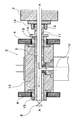
- FIG. 5 shows a cross-sectional structure of the base part 3.
- Reference numeral 13 denotes a base body having a square cross section, and bearing bushes 14 are attached to both left and right ends thereof, and the base body 13 is rotatably supported by a pair of left and right bearings 15 provided in the base part holding portion 4. ing.
- the above-mentioned horizontal flow path 5 is formed in the base body 13 at a position on the rotation center axis AA, and an extrusion flow orthogonal to the horizontal flow path 5 is formed at the center of the base body 3.
- a path 10 is formed.
- a pressure relief valve is provided as a pressure relief device 8 at the tip of the horizontal flow path 5.
- the base body 13 is connected to the drive arm of the rotating means 7 described above, and the base body 13 and the extrusion port 6 can be rotated about the rotation center axis AA.
- a cylindrical portion 16 is formed at the distal end of the screw portion 2, and the distal end of a sleeve 17 protruding from the end portion of the base body 13 is inserted into the cylindrical portion 16.
- a seal portion 12 is provided between the cylindrical portion 16 and the sleeve 17 over the entire circumference.
- the seal portion 12 may be an O-ring, but a gland packing is used in FIG.
- the sleeve 17 rotates inside the cylindrical portion 16.
- the pressure in the base part 3 at the time of extrusion molding is as high as 10 MPa or more, since the seal member 12 is arranged in this way at the connecting portion between the screw part 2 and the molding material extrusion flow path 5, extrusion molding is performed. It has a structure that can maintain the internal pressure of the hour.
- the base part 3 of the continuous extrusion molding apparatus needs to be periodically replaced, the base part 3 is rotated in the direction shown in FIG.
- the opening direction of the extrusion port 6 can be rotated to the horizontal direction as shown in FIG.
- the base part 3 is for a large-sized product having a mounting jig including about 600 kg, but can be easily rotated by operating the rotating means 7.
- the balance weight 9 is disposed at a position facing the extrusion port 6 in order to stably rotate the base portion 3.
- the pressure relief device 8 is provided in the base body 13 as means for reducing the internal pressure in the upstream part of the base part 3.
- the arrangement location of the pressure relief device 8 should be on the extension line of the forming raw material flow path conveyed in the screw portion 2 as shown in FIGS. preferable.
- the horizontal flow path 5 is extended to form the pressure release flow path 11. Since the pressure release channel 11 at the time of extrusion molding is filled with so-called “dead earth”, the molding material press-fitted from the screw portion 2 into the horizontal channel 5 flows into the orthogonal extrusion channel 10. And extruded from the extrusion port 6.
Landscapes
- Engineering & Computer Science (AREA)
- Mechanical Engineering (AREA)
- Manufacturing & Machinery (AREA)
- Chemical & Material Sciences (AREA)
- Ceramic Engineering (AREA)
- Press-Shaping Or Shaping Using Conveyers (AREA)
Abstract
Description
2 スクリュー部
3 口金部
4 口金部保持部
5 水平流路
6 押出口
7 回動手段
7a 油圧シリンダ
7b 軸
7c アーム
7d ピストンロッド
7e ジョイント
8 圧力抜き装置
9 バランスウェイト
10 押出流路
11 圧抜き流路
12 シール部材
13 口金本体
14 軸受ブッシュ
15 軸受
16 円筒部
17 スリーブ
Claims (4)
- 成形原料を水平方向に搬送するスクリューを内蔵し、スクリュー部の下流側に、押出成形用の口金部を備える連続押出成形装置であって、
前記口金部は、前記スクリュー部から流入した成形原料を水平方向に押し出す水平流路と、該水平流路と直交する押出流路と、該押出流路の先端に形成した押出口を有し、
前記口金部を保持する口金部保持部に、前記押出口の開口方向を水平方向から床面方向の間で変更自在とする回動手段を備えたことを特徴とする連続押出成形装置。 - 前記口金部は、前記回動操作前に口金上流部の内部圧力を低下させる手段として、圧力抜き装置を備えることを特徴とする請求項1記載の連続押出成形装置。
- 前記圧力抜き装置を、スクリュー部内を搬送される成形原料流路の延長線上に配置したことを特徴とする請求項2記載の連続押出成形装置。
- 請求項1記載の連続押出成形装置を用いたハニカム構造体の製造方法であって、
前記成形原料の押し出しは、前記押出口の開口方向を垂直下向きとした状態で行い、
前記口金部の交換作業は、前記押出口の開口方向を水平方向とした状態で行うことを特徴とするハニカム構造体の製造方法。
Priority Applications (4)
| Application Number | Priority Date | Filing Date | Title |
|---|---|---|---|
| JP2015506788A JP6277446B2 (ja) | 2013-03-21 | 2014-03-18 | 連続押出成形装置 |
| CN201480016715.4A CN105050781B (zh) | 2013-03-21 | 2014-03-18 | 连续挤压成形装置 |
| EP14769711.4A EP2977160B1 (en) | 2013-03-21 | 2014-03-18 | Continuous extrusion moulding apparatus |
| US14/834,618 US10207442B2 (en) | 2013-03-21 | 2015-08-25 | Continuous extrusion forming apparatus |
Applications Claiming Priority (2)
| Application Number | Priority Date | Filing Date | Title |
|---|---|---|---|
| JP2013058204 | 2013-03-21 | ||
| JP2013-058204 | 2013-03-21 |
Related Child Applications (1)
| Application Number | Title | Priority Date | Filing Date |
|---|---|---|---|
| US14/834,618 Continuation US10207442B2 (en) | 2013-03-21 | 2015-08-25 | Continuous extrusion forming apparatus |
Publications (1)
| Publication Number | Publication Date |
|---|---|
| WO2014148461A1 true WO2014148461A1 (ja) | 2014-09-25 |
Family
ID=51580140
Family Applications (1)
| Application Number | Title | Priority Date | Filing Date |
|---|---|---|---|
| PCT/JP2014/057238 Ceased WO2014148461A1 (ja) | 2013-03-21 | 2014-03-18 | 連続押出成形装置 |
Country Status (5)
| Country | Link |
|---|---|
| US (1) | US10207442B2 (ja) |
| EP (1) | EP2977160B1 (ja) |
| JP (1) | JP6277446B2 (ja) |
| CN (1) | CN105050781B (ja) |
| WO (1) | WO2014148461A1 (ja) |
Cited By (1)
| Publication number | Priority date | Publication date | Assignee | Title |
|---|---|---|---|---|
| CN110789097A (zh) * | 2019-11-20 | 2020-02-14 | 彭燕萍 | 一种注塑挤出头的安装结构 |
Families Citing this family (2)
| Publication number | Priority date | Publication date | Assignee | Title |
|---|---|---|---|---|
| US10414066B2 (en) * | 2017-01-16 | 2019-09-17 | Jing Zhang | Slurry dispense system |
| JP7582832B2 (ja) * | 2020-10-14 | 2024-11-13 | 住友重機械プロセス機器株式会社 | 撹拌装置 |
Citations (5)
| Publication number | Priority date | Publication date | Assignee | Title |
|---|---|---|---|---|
| JPS62130803A (ja) * | 1985-12-03 | 1987-06-13 | 松下電器産業株式会社 | ハニカム状構造体の製造方法 |
| JPS63230304A (ja) * | 1987-03-19 | 1988-09-26 | 日本碍子株式会社 | セラミツクスの押出し成形方法と押出し成形装置 |
| JP2003311726A (ja) * | 2002-04-19 | 2003-11-05 | Ngk Insulators Ltd | ハニカム構造体製造装置及びハニカム構造体の製造方法 |
| JP2004249513A (ja) * | 2003-02-19 | 2004-09-09 | Hoden Seimitsu Kako Kenkyusho Ltd | セラミックスシートの押し出し成形方法及びその装置 |
| JP2010221637A (ja) | 2009-03-25 | 2010-10-07 | Ngk Insulators Ltd | 押出成形装置および、それを用いた成形体の製造方法 |
Family Cites Families (11)
| Publication number | Priority date | Publication date | Assignee | Title |
|---|---|---|---|---|
| US2642898A (en) * | 1948-09-30 | 1953-06-23 | Roeblings John A Sons Co | Control casing and manufacture thereof |
| US2834047A (en) * | 1954-01-15 | 1958-05-13 | Louis H Morin | Apparatus for making extruded spiral coaxial cable |
| JPS478940Y1 (ja) | 1968-06-08 | 1972-04-05 | ||
| US4178145A (en) * | 1976-04-26 | 1979-12-11 | Kyoto Ceramic Co., Ltd. | Extrusion die for ceramic honeycomb structures |
| JPS6021049B2 (ja) * | 1977-06-28 | 1985-05-25 | 横浜ゴム株式会社 | 押出機 |
| DE2854523C2 (de) * | 1978-12-16 | 1983-07-28 | Mannesmann AG, 4000 Düsseldorf | Strangpresse zum Auspressen plastischer Kohlemasse zu Elektroden für elektrische Öfen |
| DE8022820U1 (de) * | 1980-08-27 | 1981-01-22 | Weisert, Loser & Sohn Gmbh & Co, 7500 Karlsruhe | Vorrichtung zum einfuehren einer aus einer foerdereinrichtung gedrueckten bonbon-fuellung in eine strangformmaschine |
| JP2000317924A (ja) * | 1999-05-07 | 2000-11-21 | Miyazaki Tekko Kk | スクリューピストン式真空押出成形機 |
| JP3560338B2 (ja) * | 2002-04-19 | 2004-09-02 | 日本碍子株式会社 | ハニカム構造体製造装置、及びハニカム構造体の製造方法 |
| AU2003271148A1 (en) * | 2003-10-09 | 2005-04-27 | Misawa Homes Co., Ltd. | Extrusion molding machine |
| JP5578696B2 (ja) * | 2008-09-30 | 2014-08-27 | ユニバース株式会社 | セラミック成形体の連続成形装置 |
-
2014
- 2014-03-18 JP JP2015506788A patent/JP6277446B2/ja active Active
- 2014-03-18 WO PCT/JP2014/057238 patent/WO2014148461A1/ja not_active Ceased
- 2014-03-18 CN CN201480016715.4A patent/CN105050781B/zh active Active
- 2014-03-18 EP EP14769711.4A patent/EP2977160B1/en active Active
-
2015
- 2015-08-25 US US14/834,618 patent/US10207442B2/en active Active
Patent Citations (5)
| Publication number | Priority date | Publication date | Assignee | Title |
|---|---|---|---|---|
| JPS62130803A (ja) * | 1985-12-03 | 1987-06-13 | 松下電器産業株式会社 | ハニカム状構造体の製造方法 |
| JPS63230304A (ja) * | 1987-03-19 | 1988-09-26 | 日本碍子株式会社 | セラミツクスの押出し成形方法と押出し成形装置 |
| JP2003311726A (ja) * | 2002-04-19 | 2003-11-05 | Ngk Insulators Ltd | ハニカム構造体製造装置及びハニカム構造体の製造方法 |
| JP2004249513A (ja) * | 2003-02-19 | 2004-09-09 | Hoden Seimitsu Kako Kenkyusho Ltd | セラミックスシートの押し出し成形方法及びその装置 |
| JP2010221637A (ja) | 2009-03-25 | 2010-10-07 | Ngk Insulators Ltd | 押出成形装置および、それを用いた成形体の製造方法 |
Non-Patent Citations (1)
| Title |
|---|
| See also references of EP2977160A4 |
Cited By (2)
| Publication number | Priority date | Publication date | Assignee | Title |
|---|---|---|---|---|
| CN110789097A (zh) * | 2019-11-20 | 2020-02-14 | 彭燕萍 | 一种注塑挤出头的安装结构 |
| CN110789097B (zh) * | 2019-11-20 | 2021-10-12 | 嵊州亿源投资管理有限公司 | 一种注塑挤出头的安装结构 |
Also Published As
| Publication number | Publication date |
|---|---|
| CN105050781B (zh) | 2017-02-15 |
| EP2977160A4 (en) | 2017-04-26 |
| CN105050781A (zh) | 2015-11-11 |
| EP2977160B1 (en) | 2019-02-20 |
| US20150360407A1 (en) | 2015-12-17 |
| JP6277446B2 (ja) | 2018-02-14 |
| US10207442B2 (en) | 2019-02-19 |
| JPWO2014148461A1 (ja) | 2017-02-16 |
| EP2977160A1 (en) | 2016-01-27 |
Similar Documents
| Publication | Publication Date | Title |
|---|---|---|
| EP3144121B1 (en) | Plasticizing delivery method and device using eccentric rotor and having pulsed volume deformation | |
| JP6277446B2 (ja) | 連続押出成形装置 | |
| CN204749210U (zh) | 带空心螺杆的挤出机 | |
| CN203779831U (zh) | 可精细调节薄膜厚度的吹塑模具 | |
| CN104608362B (zh) | 塑料挤出机机筒 | |
| CN103568207B (zh) | 一种注塑机筒安装结构 | |
| CN110508651A (zh) | 一种多点成形自由弯管装置 | |
| CN206066917U (zh) | 一种多段式复合螺杆 | |
| CN106182689B (zh) | 一种多段式复合螺杆 | |
| CN104607606B (zh) | 一种连续铸挤成型装置 | |
| CN106426850A (zh) | 一种去黑线装置 | |
| CN207327442U (zh) | 一种转轴式双色注塑机 | |
| CN205364486U (zh) | 一种挤出机螺杆安装机构 | |
| CN206446092U (zh) | 组合式机筒 | |
| CN203110299U (zh) | Ps发泡片材挤出口模的厚薄调整装置 | |
| CN111113828A (zh) | 螺杆和注塑机 | |
| CN202726013U (zh) | 压铸机打料杆 | |
| CN103128949A (zh) | 塑料挤出机 | |
| CN204339715U (zh) | 一种装卸机 | |
| CN203899572U (zh) | 自动压紧式辊轮旋压挤出机 | |
| CN103394624A (zh) | 压力机开式冲孔用可调定位装置 | |
| CN206446088U (zh) | 一种锥双螺杆 | |
| CN206446089U (zh) | 大型螺杆 | |
| CN109986755A (zh) | 一种分段式塑化注射装置及其加工工艺 | |
| CN105109054A (zh) | 大口径塑钢缠绕管法兰的制造方法 |
Legal Events
| Date | Code | Title | Description |
|---|---|---|---|
| WWE | Wipo information: entry into national phase |
Ref document number: 201480016715.4 Country of ref document: CN |
|
| 121 | Ep: the epo has been informed by wipo that ep was designated in this application |
Ref document number: 14769711 Country of ref document: EP Kind code of ref document: A1 |
|
| ENP | Entry into the national phase |
Ref document number: 2015506788 Country of ref document: JP Kind code of ref document: A |
|
| WWE | Wipo information: entry into national phase |
Ref document number: 2014769711 Country of ref document: EP |
|
| NENP | Non-entry into the national phase |
Ref country code: DE |