WO2014148506A1 - 還元剤噴射装置、排ガス処理装置及び排ガス処理方法 - Google Patents
還元剤噴射装置、排ガス処理装置及び排ガス処理方法 Download PDFInfo
- Publication number
- WO2014148506A1 WO2014148506A1 PCT/JP2014/057385 JP2014057385W WO2014148506A1 WO 2014148506 A1 WO2014148506 A1 WO 2014148506A1 JP 2014057385 W JP2014057385 W JP 2014057385W WO 2014148506 A1 WO2014148506 A1 WO 2014148506A1
- Authority
- WO
- WIPO (PCT)
- Prior art keywords
- honeycomb structure
- urea
- exhaust gas
- reducing agent
- injection device
- Prior art date
- Legal status (The legal status is an assumption and is not a legal conclusion. Google has not performed a legal analysis and makes no representation as to the accuracy of the status listed.)
- Ceased
Links
Images


Classifications
-
- F—MECHANICAL ENGINEERING; LIGHTING; HEATING; WEAPONS; BLASTING
- F01—MACHINES OR ENGINES IN GENERAL; ENGINE PLANTS IN GENERAL; STEAM ENGINES
- F01N—GAS-FLOW SILENCERS OR EXHAUST APPARATUS FOR MACHINES OR ENGINES IN GENERAL; GAS-FLOW SILENCERS OR EXHAUST APPARATUS FOR INTERNAL-COMBUSTION ENGINES
- F01N3/00—Exhaust or silencing apparatus having means for purifying, rendering innocuous, or otherwise treating exhaust
- F01N3/02—Exhaust or silencing apparatus having means for purifying, rendering innocuous, or otherwise treating exhaust for cooling, or for removing solid constituents of, exhaust
- F01N3/021—Exhaust or silencing apparatus having means for purifying, rendering innocuous, or otherwise treating exhaust for cooling, or for removing solid constituents of, exhaust by means of filters
- F01N3/022—Exhaust or silencing apparatus having means for purifying, rendering innocuous, or otherwise treating exhaust for cooling, or for removing solid constituents of, exhaust by means of filters characterised by specially adapted filtering structure, e.g. honeycomb, mesh or fibrous
- F01N3/0222—Exhaust or silencing apparatus having means for purifying, rendering innocuous, or otherwise treating exhaust for cooling, or for removing solid constituents of, exhaust by means of filters characterised by specially adapted filtering structure, e.g. honeycomb, mesh or fibrous the structure being monolithic, e.g. honeycombs
-
- F—MECHANICAL ENGINEERING; LIGHTING; HEATING; WEAPONS; BLASTING
- F01—MACHINES OR ENGINES IN GENERAL; ENGINE PLANTS IN GENERAL; STEAM ENGINES
- F01N—GAS-FLOW SILENCERS OR EXHAUST APPARATUS FOR MACHINES OR ENGINES IN GENERAL; GAS-FLOW SILENCERS OR EXHAUST APPARATUS FOR INTERNAL-COMBUSTION ENGINES
- F01N3/00—Exhaust or silencing apparatus having means for purifying, rendering innocuous, or otherwise treating exhaust
- F01N3/08—Exhaust or silencing apparatus having means for purifying, rendering innocuous, or otherwise treating exhaust for rendering innocuous
- F01N3/10—Exhaust or silencing apparatus having means for purifying, rendering innocuous, or otherwise treating exhaust for rendering innocuous by thermal or catalytic conversion of noxious components of exhaust
- F01N3/18—Exhaust or silencing apparatus having means for purifying, rendering innocuous, or otherwise treating exhaust for rendering innocuous by thermal or catalytic conversion of noxious components of exhaust characterised by methods of operation; Control
- F01N3/20—Exhaust or silencing apparatus having means for purifying, rendering innocuous, or otherwise treating exhaust for rendering innocuous by thermal or catalytic conversion of noxious components of exhaust characterised by methods of operation; Control specially adapted for catalytic conversion
- F01N3/206—Adding periodically or continuously substances to exhaust gases for promoting purification, e.g. catalytic material in liquid form, NOx reducing agents
- F01N3/208—Control of selective catalytic reduction [SCR], e.g. by adjusting the dosing of reducing agent
-
- B—PERFORMING OPERATIONS; TRANSPORTING
- B01—PHYSICAL OR CHEMICAL PROCESSES OR APPARATUS IN GENERAL
- B01D—SEPARATION
- B01D53/00—Separation of gases or vapours; Recovering vapours of volatile solvents from gases; Chemical or biological purification of waste gases, e.g. engine exhaust gases, smoke, fumes, flue gases, aerosols
- B01D53/34—Chemical or biological purification of waste gases
- B01D53/74—General processes for purification of waste gases; Apparatus or devices specially adapted therefor
- B01D53/86—Catalytic processes
- B01D53/90—Injecting reactants
-
- B—PERFORMING OPERATIONS; TRANSPORTING
- B01—PHYSICAL OR CHEMICAL PROCESSES OR APPARATUS IN GENERAL
- B01D—SEPARATION
- B01D53/00—Separation of gases or vapours; Recovering vapours of volatile solvents from gases; Chemical or biological purification of waste gases, e.g. engine exhaust gases, smoke, fumes, flue gases, aerosols
- B01D53/34—Chemical or biological purification of waste gases
- B01D53/92—Chemical or biological purification of waste gases of engine exhaust gases
- B01D53/94—Chemical or biological purification of waste gases of engine exhaust gases by catalytic processes
- B01D53/9404—Removing only nitrogen compounds
- B01D53/9409—Nitrogen oxides
- B01D53/9431—Processes characterised by a specific device
-
- B—PERFORMING OPERATIONS; TRANSPORTING
- B01—PHYSICAL OR CHEMICAL PROCESSES OR APPARATUS IN GENERAL
- B01D—SEPARATION
- B01D53/00—Separation of gases or vapours; Recovering vapours of volatile solvents from gases; Chemical or biological purification of waste gases, e.g. engine exhaust gases, smoke, fumes, flue gases, aerosols
- B01D53/34—Chemical or biological purification of waste gases
- B01D53/92—Chemical or biological purification of waste gases of engine exhaust gases
- B01D53/94—Chemical or biological purification of waste gases of engine exhaust gases by catalytic processes
- B01D53/9459—Removing one or more of nitrogen oxides, carbon monoxide, or hydrocarbons by multiple successive catalytic functions; systems with more than one different function, e.g. zone coated catalysts
- B01D53/9477—Removing one or more of nitrogen oxides, carbon monoxide, or hydrocarbons by multiple successive catalytic functions; systems with more than one different function, e.g. zone coated catalysts with catalysts positioned on separate bricks, e.g. exhaust systems
-
- B—PERFORMING OPERATIONS; TRANSPORTING
- B01—PHYSICAL OR CHEMICAL PROCESSES OR APPARATUS IN GENERAL
- B01J—CHEMICAL OR PHYSICAL PROCESSES, e.g. CATALYSIS OR COLLOID CHEMISTRY; THEIR RELEVANT APPARATUS
- B01J27/00—Catalysts comprising the elements or compounds of halogens, sulfur, selenium, tellurium, phosphorus or nitrogen; Catalysts comprising carbon compounds
- B01J27/20—Carbon compounds
- B01J27/22—Carbides
- B01J27/224—Silicon carbide
-
- B—PERFORMING OPERATIONS; TRANSPORTING
- B01—PHYSICAL OR CHEMICAL PROCESSES OR APPARATUS IN GENERAL
- B01J—CHEMICAL OR PHYSICAL PROCESSES, e.g. CATALYSIS OR COLLOID CHEMISTRY; THEIR RELEVANT APPARATUS
- B01J35/00—Catalysts, in general, characterised by their form or physical properties
- B01J35/50—Catalysts, in general, characterised by their form or physical properties characterised by their shape or configuration
- B01J35/56—Foraminous structures having flow-through passages or channels, e.g. grids or three-dimensional [3D] monoliths
- B01J35/57—Honeycombs
-
- F—MECHANICAL ENGINEERING; LIGHTING; HEATING; WEAPONS; BLASTING
- F01—MACHINES OR ENGINES IN GENERAL; ENGINE PLANTS IN GENERAL; STEAM ENGINES
- F01N—GAS-FLOW SILENCERS OR EXHAUST APPARATUS FOR MACHINES OR ENGINES IN GENERAL; GAS-FLOW SILENCERS OR EXHAUST APPARATUS FOR INTERNAL-COMBUSTION ENGINES
- F01N3/00—Exhaust or silencing apparatus having means for purifying, rendering innocuous, or otherwise treating exhaust
- F01N3/08—Exhaust or silencing apparatus having means for purifying, rendering innocuous, or otherwise treating exhaust for rendering innocuous
- F01N3/10—Exhaust or silencing apparatus having means for purifying, rendering innocuous, or otherwise treating exhaust for rendering innocuous by thermal or catalytic conversion of noxious components of exhaust
- F01N3/18—Exhaust or silencing apparatus having means for purifying, rendering innocuous, or otherwise treating exhaust for rendering innocuous by thermal or catalytic conversion of noxious components of exhaust characterised by methods of operation; Control
- F01N3/20—Exhaust or silencing apparatus having means for purifying, rendering innocuous, or otherwise treating exhaust for rendering innocuous by thermal or catalytic conversion of noxious components of exhaust characterised by methods of operation; Control specially adapted for catalytic conversion
- F01N3/2006—Periodically heating or cooling catalytic reactors, e.g. at cold starting or overheating
- F01N3/2013—Periodically heating or cooling catalytic reactors, e.g. at cold starting or overheating using electric or magnetic heating means
- F01N3/2026—Periodically heating or cooling catalytic reactors, e.g. at cold starting or overheating using electric or magnetic heating means directly electrifying the catalyst substrate, i.e. heating the electrically conductive catalyst substrate by joule effect
-
- F—MECHANICAL ENGINEERING; LIGHTING; HEATING; WEAPONS; BLASTING
- F01—MACHINES OR ENGINES IN GENERAL; ENGINE PLANTS IN GENERAL; STEAM ENGINES
- F01N—GAS-FLOW SILENCERS OR EXHAUST APPARATUS FOR MACHINES OR ENGINES IN GENERAL; GAS-FLOW SILENCERS OR EXHAUST APPARATUS FOR INTERNAL-COMBUSTION ENGINES
- F01N3/00—Exhaust or silencing apparatus having means for purifying, rendering innocuous, or otherwise treating exhaust
- F01N3/08—Exhaust or silencing apparatus having means for purifying, rendering innocuous, or otherwise treating exhaust for rendering innocuous
- F01N3/10—Exhaust or silencing apparatus having means for purifying, rendering innocuous, or otherwise treating exhaust for rendering innocuous by thermal or catalytic conversion of noxious components of exhaust
- F01N3/18—Exhaust or silencing apparatus having means for purifying, rendering innocuous, or otherwise treating exhaust for rendering innocuous by thermal or catalytic conversion of noxious components of exhaust characterised by methods of operation; Control
- F01N3/20—Exhaust or silencing apparatus having means for purifying, rendering innocuous, or otherwise treating exhaust for rendering innocuous by thermal or catalytic conversion of noxious components of exhaust characterised by methods of operation; Control specially adapted for catalytic conversion
- F01N3/206—Adding periodically or continuously substances to exhaust gases for promoting purification, e.g. catalytic material in liquid form, NOx reducing agents
- F01N3/2066—Selective catalytic reduction [SCR]
-
- F—MECHANICAL ENGINEERING; LIGHTING; HEATING; WEAPONS; BLASTING
- F01—MACHINES OR ENGINES IN GENERAL; ENGINE PLANTS IN GENERAL; STEAM ENGINES
- F01N—GAS-FLOW SILENCERS OR EXHAUST APPARATUS FOR MACHINES OR ENGINES IN GENERAL; GAS-FLOW SILENCERS OR EXHAUST APPARATUS FOR INTERNAL-COMBUSTION ENGINES
- F01N3/00—Exhaust or silencing apparatus having means for purifying, rendering innocuous, or otherwise treating exhaust
- F01N3/08—Exhaust or silencing apparatus having means for purifying, rendering innocuous, or otherwise treating exhaust for rendering innocuous
- F01N3/10—Exhaust or silencing apparatus having means for purifying, rendering innocuous, or otherwise treating exhaust for rendering innocuous by thermal or catalytic conversion of noxious components of exhaust
- F01N3/24—Exhaust or silencing apparatus having means for purifying, rendering innocuous, or otherwise treating exhaust for rendering innocuous by thermal or catalytic conversion of noxious components of exhaust characterised by constructional aspects of converting apparatus
- F01N3/28—Construction of catalytic reactors
- F01N3/2839—Arrangements for mounting catalyst support in housing, e.g. with means for compensating thermal expansion or vibration
- F01N3/2842—Arrangements for mounting catalyst support in housing, e.g. with means for compensating thermal expansion or vibration specially adapted for monolithic supports, e.g. of honeycomb type
-
- B—PERFORMING OPERATIONS; TRANSPORTING
- B01—PHYSICAL OR CHEMICAL PROCESSES OR APPARATUS IN GENERAL
- B01D—SEPARATION
- B01D2251/00—Reactants
- B01D2251/20—Reductants
- B01D2251/206—Ammonium compounds
- B01D2251/2067—Urea
-
- B—PERFORMING OPERATIONS; TRANSPORTING
- B01—PHYSICAL OR CHEMICAL PROCESSES OR APPARATUS IN GENERAL
- B01D—SEPARATION
- B01D2255/00—Catalysts
- B01D2255/10—Noble metals or compounds thereof
- B01D2255/102—Platinum group metals
- B01D2255/1021—Platinum
-
- B—PERFORMING OPERATIONS; TRANSPORTING
- B01—PHYSICAL OR CHEMICAL PROCESSES OR APPARATUS IN GENERAL
- B01D—SEPARATION
- B01D2255/00—Catalysts
- B01D2255/10—Noble metals or compounds thereof
- B01D2255/102—Platinum group metals
- B01D2255/1023—Palladium
-
- B—PERFORMING OPERATIONS; TRANSPORTING
- B01—PHYSICAL OR CHEMICAL PROCESSES OR APPARATUS IN GENERAL
- B01D—SEPARATION
- B01D2255/00—Catalysts
- B01D2255/10—Noble metals or compounds thereof
- B01D2255/102—Platinum group metals
- B01D2255/1025—Rhodium
-
- B—PERFORMING OPERATIONS; TRANSPORTING
- B01—PHYSICAL OR CHEMICAL PROCESSES OR APPARATUS IN GENERAL
- B01D—SEPARATION
- B01D2255/00—Catalysts
- B01D2255/20—Metals or compounds thereof
- B01D2255/207—Transition metals
- B01D2255/20723—Vanadium
-
- B—PERFORMING OPERATIONS; TRANSPORTING
- B01—PHYSICAL OR CHEMICAL PROCESSES OR APPARATUS IN GENERAL
- B01D—SEPARATION
- B01D2255/00—Catalysts
- B01D2255/50—Zeolites
-
- B—PERFORMING OPERATIONS; TRANSPORTING
- B01—PHYSICAL OR CHEMICAL PROCESSES OR APPARATUS IN GENERAL
- B01D—SEPARATION
- B01D2257/00—Components to be removed
- B01D2257/40—Nitrogen compounds
- B01D2257/404—Nitrogen oxides other than dinitrogen oxide
-
- B—PERFORMING OPERATIONS; TRANSPORTING
- B01—PHYSICAL OR CHEMICAL PROCESSES OR APPARATUS IN GENERAL
- B01D—SEPARATION
- B01D2257/00—Components to be removed
- B01D2257/40—Nitrogen compounds
- B01D2257/406—Ammonia
-
- B—PERFORMING OPERATIONS; TRANSPORTING
- B01—PHYSICAL OR CHEMICAL PROCESSES OR APPARATUS IN GENERAL
- B01D—SEPARATION
- B01D2257/00—Components to be removed
- B01D2257/50—Carbon oxides
- B01D2257/502—Carbon monoxide
-
- B—PERFORMING OPERATIONS; TRANSPORTING
- B01—PHYSICAL OR CHEMICAL PROCESSES OR APPARATUS IN GENERAL
- B01D—SEPARATION
- B01D2257/00—Components to be removed
- B01D2257/70—Organic compounds not provided for in groups B01D2257/00 - B01D2257/602
- B01D2257/702—Hydrocarbons
-
- F—MECHANICAL ENGINEERING; LIGHTING; HEATING; WEAPONS; BLASTING
- F01—MACHINES OR ENGINES IN GENERAL; ENGINE PLANTS IN GENERAL; STEAM ENGINES
- F01N—GAS-FLOW SILENCERS OR EXHAUST APPARATUS FOR MACHINES OR ENGINES IN GENERAL; GAS-FLOW SILENCERS OR EXHAUST APPARATUS FOR INTERNAL-COMBUSTION ENGINES
- F01N2240/00—Combination or association of two or more different exhaust treating devices, or of at least one such device with an auxiliary device, not covered by indexing codes F01N2230/00 or F01N2250/00, one of the devices being
- F01N2240/16—Combination or association of two or more different exhaust treating devices, or of at least one such device with an auxiliary device, not covered by indexing codes F01N2230/00 or F01N2250/00, one of the devices being an electric heater, i.e. a resistance heater
-
- F—MECHANICAL ENGINEERING; LIGHTING; HEATING; WEAPONS; BLASTING
- F01—MACHINES OR ENGINES IN GENERAL; ENGINE PLANTS IN GENERAL; STEAM ENGINES
- F01N—GAS-FLOW SILENCERS OR EXHAUST APPARATUS FOR MACHINES OR ENGINES IN GENERAL; GAS-FLOW SILENCERS OR EXHAUST APPARATUS FOR INTERNAL-COMBUSTION ENGINES
- F01N2240/00—Combination or association of two or more different exhaust treating devices, or of at least one such device with an auxiliary device, not covered by indexing codes F01N2230/00 or F01N2250/00, one of the devices being
- F01N2240/40—Combination or association of two or more different exhaust treating devices, or of at least one such device with an auxiliary device, not covered by indexing codes F01N2230/00 or F01N2250/00, one of the devices being a hydrolysis catalyst
-
- F—MECHANICAL ENGINEERING; LIGHTING; HEATING; WEAPONS; BLASTING
- F01—MACHINES OR ENGINES IN GENERAL; ENGINE PLANTS IN GENERAL; STEAM ENGINES
- F01N—GAS-FLOW SILENCERS OR EXHAUST APPARATUS FOR MACHINES OR ENGINES IN GENERAL; GAS-FLOW SILENCERS OR EXHAUST APPARATUS FOR INTERNAL-COMBUSTION ENGINES
- F01N2330/00—Structure of catalyst support or particle filter
- F01N2330/30—Honeycomb supports characterised by their structural details
-
- F—MECHANICAL ENGINEERING; LIGHTING; HEATING; WEAPONS; BLASTING
- F01—MACHINES OR ENGINES IN GENERAL; ENGINE PLANTS IN GENERAL; STEAM ENGINES
- F01N—GAS-FLOW SILENCERS OR EXHAUST APPARATUS FOR MACHINES OR ENGINES IN GENERAL; GAS-FLOW SILENCERS OR EXHAUST APPARATUS FOR INTERNAL-COMBUSTION ENGINES
- F01N2610/00—Adding substances to exhaust gases
- F01N2610/02—Adding substances to exhaust gases the substance being ammonia or urea
-
- F—MECHANICAL ENGINEERING; LIGHTING; HEATING; WEAPONS; BLASTING
- F01—MACHINES OR ENGINES IN GENERAL; ENGINE PLANTS IN GENERAL; STEAM ENGINES
- F01N—GAS-FLOW SILENCERS OR EXHAUST APPARATUS FOR MACHINES OR ENGINES IN GENERAL; GAS-FLOW SILENCERS OR EXHAUST APPARATUS FOR INTERNAL-COMBUSTION ENGINES
- F01N2610/00—Adding substances to exhaust gases
- F01N2610/10—Adding substances to exhaust gases the substance being heated, e.g. by heating tank or supply line of the added substance
- F01N2610/105—Control thereof
-
- F—MECHANICAL ENGINEERING; LIGHTING; HEATING; WEAPONS; BLASTING
- F01—MACHINES OR ENGINES IN GENERAL; ENGINE PLANTS IN GENERAL; STEAM ENGINES
- F01N—GAS-FLOW SILENCERS OR EXHAUST APPARATUS FOR MACHINES OR ENGINES IN GENERAL; GAS-FLOW SILENCERS OR EXHAUST APPARATUS FOR INTERNAL-COMBUSTION ENGINES
- F01N2610/00—Adding substances to exhaust gases
- F01N2610/14—Arrangements for the supply of substances, e.g. conduits
- F01N2610/1453—Sprayers or atomisers; Arrangement thereof in the exhaust apparatus
- F01N2610/146—Control thereof, e.g. control of injectors or injection valves
-
- Y—GENERAL TAGGING OF NEW TECHNOLOGICAL DEVELOPMENTS; GENERAL TAGGING OF CROSS-SECTIONAL TECHNOLOGIES SPANNING OVER SEVERAL SECTIONS OF THE IPC; TECHNICAL SUBJECTS COVERED BY FORMER USPC CROSS-REFERENCE ART COLLECTIONS [XRACs] AND DIGESTS
- Y02—TECHNOLOGIES OR APPLICATIONS FOR MITIGATION OR ADAPTATION AGAINST CLIMATE CHANGE
- Y02T—CLIMATE CHANGE MITIGATION TECHNOLOGIES RELATED TO TRANSPORTATION
- Y02T10/00—Road transport of goods or passengers
- Y02T10/10—Internal combustion engine [ICE] based vehicles
- Y02T10/12—Improving ICE efficiencies
Definitions
- the present invention relates to a reducing agent injection device, an exhaust gas treatment device, and an exhaust gas treatment method. More specifically, the present invention relates to a reducing agent injection device capable of generating and injecting ammonia from a urea solution with less energy.
- the present invention also relates to an exhaust gas treatment apparatus that includes the reducing agent injection device and can treat NO X in the exhaust gas with a small amount of energy even when the exhaust gas is at a low temperature.
- the present invention also relates to an exhaust gas treatment method capable of treating NO X in exhaust gas with a small amount of energy even when the exhaust gas is at a low temperature using the exhaust gas treatment device.
- the exhaust gas purification device described in Patent Document 1 has a catalyst (SCR catalyst) attached to an exhaust pipe of an engine and means for injecting urea water into the exhaust pipe between the engine and the catalyst. Then, urea water injection means for mixing urea water and exhaust gas, reacting with a specific component in the exhaust gas by a catalyst, and mixing urea water with the exhaust gas is provided at a plurality of locations.
- SCR catalyst catalyst
- urea water injection means for mixing urea water and exhaust gas, reacting with a specific component in the exhaust gas by a catalyst, and mixing urea water with the exhaust gas is provided at a plurality of locations.
- the device described in Patent Document 2 is a device for reducing nitrogen oxides in exhaust gas of an internal combustion engine. And it has a thermal decomposition reactor for producing ammonia from solid urea, a heating device, and an SCR catalyst, and allows the ammonia produced from solid urea to flow into the SCR catalyst.
- the apparatus described in Patent Document 3 is an apparatus for evaporating at least one of a reducing agent precursor (urea) solution and a reducing agent precursor (urea).
- the evaporated substance (urea) is to be hydrolyzed by a hydrolysis catalytic converter disposed on the downstream side.
- the said apparatus has a heating element arrange
- what was hydrolyzed by the hydrolysis catalytic converter (ammonia) is used for the reduction treatment in the SCR catalytic converter.
- the exhaust gas purifying device described in Patent Document 1 decomposes urea water with the heat of exhaust gas, and therefore has a problem that urea does not easily react when the temperature of exhaust gas decreases due to improvement in fuel efficiency of the engine or the like. .
- Patent Document 2 uses solid urea, but it is difficult to transport the solid urea to the reaction apparatus, and for storage, the moisture is adsorbed unless the moisture is completely shut off. Furthermore, there is a problem that transportation becomes difficult.
- the shape of the heating element is not a shape suitable for evaporating at least one of the reducing agent precursor solution and the reducing agent precursor with less energy, and the thermal decomposition is small. There was a problem that it was difficult to do with energy.
- the present invention has been made in view of such problems of the prior art.
- the present invention is characterized by providing a reducing agent injection device capable of generating and injecting ammonia (reducing agent) from a urea solution with less energy.
- the present invention includes the reducing agent injection apparatus, even the exhaust gas is a low temperature, and providing an exhaust gas treatment apparatus capable of performing processing of the NO X in the exhaust gas with less energy.
- the present invention uses the exhaust gas treatment apparatus, even the exhaust gas is a low temperature, and providing an exhaust gas processing method capable of performing processing of the NO X in the exhaust gas with less energy.
- the present invention provides the following reducing agent injection device, exhaust gas treatment device, and exhaust gas treatment method.
- Cylindrical honeycomb structure having partition walls that form a plurality of cells that serve as fluid flow paths and extend from a first end surface that is an end surface on the fluid inflow side to a second end surface that is an end surface on the fluid outflow side.
- a honeycomb structure having a pair of electrode portions disposed on a side surface of the honeycomb structure portion, and a urea spraying device for spraying a urea aqueous solution in a mist form, each of the pair of electrode portions being the honeycomb In the cross section that is formed in a band shape extending in the cell extending direction of the structure portion and is orthogonal to the cell extending direction, one electrode portion of the pair of electrode portions is connected to the other electrode portion of the pair of electrode portions.
- the urea aqueous solution disposed on the opposite side across the center of the honeycomb structure portion and sprayed from the urea spraying device is supplied into the cell from the first end face of the honeycomb structure portion. Then, urea in the urea aqueous solution supplied into the cell is heated and hydrolyzed in the honeycomb structure portion that is energized and heated to generate ammonia, and the ammonia is formed from the second end face to the honeycomb structure.
- a reducing agent injection device that is discharged to the outside of the unit and injects the ammonia to the outside.
- honeycomb structure portion includes a silicon-silicon carbide composite material or silicon carbide as a main component.
- the urea aqueous solution is sprayed from the urea spraying device toward the first end face of the honeycomb structure, the spraying direction of the urea aqueous solution from the urea spraying device, and the cells of the honeycomb structure part Any of [1] to [5], wherein an angle with a direction parallel to a direction in which the urea spraying apparatus extends and a direction from the urea spraying device toward the first end face of the honeycomb structure is 5 to 60 °. Reducing agent injection device.
- urea injection measure is a solenoid type, a piezoelectric actuator type, an ultrasonic type, or an atomizer type.
- An exhaust pipe for flowing an exhaust gas containing NO X , a reducing agent injection device according to any one of [1] to [9] for injecting ammonia into the exhaust pipe, and the ammonia in the exhaust pipe An exhaust gas treatment apparatus comprising an SCR catalyst arranged on the downstream side of a position to be injected.
- the temperature is calculated from the resistance value of the honeycomb structure, and the temperature of the honeycomb structure is controlled so that the calculated temperature becomes a desired temperature.
- the urea aqueous solution sprayed by the urea spraying device is supplied into the cells of the honeycomb structure. Then, urea in the aqueous urea solution is heated and hydrolyzed in the honeycomb structure heated by energization to produce ammonia. And the produced
- the reducing agent injection apparatus of the present invention since the reducing agent injection apparatus of the present invention is provided, ammonia can be generated from the urea aqueous solution with less energy even if the exhaust gas is at a low temperature. And it is possible to treat NO X in the exhaust gas with less energy.
- NO X in the exhaust gas can be treated with a small amount of energy even when the exhaust gas is at a low temperature.
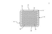
- FIG. 1 is a plan view schematically showing an end face of a honeycomb structure constituting one embodiment of a reducing agent injection apparatus of the present invention.
- FIG. 6 is a plan view schematically showing an end face of a honeycomb structure constituting another embodiment of the reducing agent injection device of the present invention.
- FIG. 6 is a plan view schematically showing an end face of a honeycomb structure constituting another embodiment of the reducing agent injection device of the present invention.
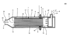
- an embodiment of the reducing agent injection device 100 of the present invention includes a honeycomb structure 1 and a urea spray device 2 that sprays an aqueous urea solution in a mist form.
- the honeycomb structure 1 includes a tubular honeycomb structure portion 11 and a pair of electrode portions 12 and 12 disposed on the side surfaces of the honeycomb structure portion 11.
- the honeycomb structure portion 11 defines “a plurality of cells 16 that extend from the first end surface 13 that serves as a fluid flow path and is the end surface on the fluid inflow side to the second end surface 14 that is the end surface on the fluid outflow side”. It has a partition 15 ”.
- Each of the pair of electrode portions 12 and 12 is formed in a strip shape extending in the extending direction of the cells 16 of the honeycomb structure portion 11.
- one electrode portion 12 in the pair of electrode portions 12, 12 is centered on the honeycomb structure portion 11 with respect to the other electrode portion 12 in the pair of electrode portions 12, 12. It is arrange
- the urea aqueous solution a2 sprayed from the urea spray device 2 is supplied into the cell 16 from the first end face 13 of the honeycomb structure portion 11.
- FIG. 1 is a schematic diagram showing a cross section (a cross section parallel to the extending direction of the cells 16 of the honeycomb structure 11) of an embodiment of the reducing agent injection device 100 of the present invention.
- the urea aqueous solution a2 sprayed from the urea spray device 2 is supplied into the cells 16 of the honeycomb structure 1. Then, urea in the aqueous urea solution is heated and hydrolyzed in the honeycomb structure 1 that is energized and heated to generate ammonia. And the produced ammonia b is injected outside. And since the honeycomb structure 1 has a large surface area and a small pressure loss, ammonia can be generated from the urea solution with a small amount of energy.
- the raw material for generating ammonia is an aqueous urea solution.
- AdBlue AdBlue
- VDA German Automobile Manufacturers Association
- the case where the urea aqueous solution is heated by the honeycomb structure is compared with the case where it is heated by the nichrome wire.
- the surface area per 1 cm 3 is about 27.73 cm 2 .
- a nichrome wire having a diameter of 0.5 mm is used to make the surface area 27.73 cm 2 . It is difficult to store this length of nichrome wire in 1 cm 3 in a state in which “a passage through which an aqueous urea solution flows, such as cells in a honeycomb structure” is secured.
- the heat transfer area and temperature of the heating member are the controlling factors. Therefore, when heating a certain amount of urea aqueous solution, if the area of the heating member is small, it is necessary to increase the temperature and a large amount of energy is required. From the above, the method of conducting heating using a honeycomb structure can heat an aqueous urea solution with less energy and ammonia with less energy compared to the case of using a linear heating member such as a nichrome wire. Can be generated.
- the honeycomb structure 1 and the urea spray device 2 are accommodated in a cylindrical outer cylinder 4.
- the honeycomb structure 1 is fixed in the outer cylinder 4 by an insulating holding portion 5.
- the first end face 13 of the honeycomb structure portion 11 is preferably square.
- the shape of the first end face 13 is not limited to a square, and may be a rectangle, other polygons, a circle, an ellipse, or the like. Note that the shape of the first end face 13 is the same as the shape of the second end face 14, and it is preferable that the shape of the cross section perpendicular to the cell 16 extending direction of the honeycomb structure portion 11 is also the same.
- the shape of the outer tube 4 “cross section orthogonal to the direction from the inlet side end 21 toward the outlet side end 22” is orthogonal to the “cell 16 extending direction” of the honeycomb structure 11. It is preferable that the shape is the same type as “the shape of the cross section to be formed” (the shape of the honeycomb structure portion).
- “the same type of shape” means that “the shape of the honeycomb structure” is also a square when the “shape of the outer cylinder” is a square, and “the shape of the honeycomb structure” when the “shape of the outer cylinder” is a rectangle. “Shape” also means rectangular.
- the ratio of the length to the length is the same. There is no need.
- the size of the “cross section perpendicular to the extending direction of the cells 16” of the honeycomb structure 11 is smaller than the size of the “cross section perpendicular to the central axis” of the outer cylinder 4.
- a urea spray space 3 is formed between the first end face 13 of the honeycomb structure portion 11 and the urea spray device 2.
- a urea spray space 3 between the first end face 13 of the honeycomb structure 1 and the urea spray device 2 is preferably formed in the outer cylinder 4.
- the urea spray space 3 is a space formed by the first end face 13 of the honeycomb structure 1, the urea spray device 2, and the outer cylinder 4. Substances in the urea spray space 3 (mist-like droplets, gas, etc.), except when “flows into the honeycomb structure 1 from the first end face 13 of the honeycomb structure 1 and is discharged to the outside”, Cannot move outside.
- the walls of the first end surface 13 of the honeycomb structure 1, the urea spray device 2, and the outer cylinder 4 that form the urea spray space 3 are added when ammonia is generated by heating (hydrolysis of urea). It has pressure resistance that can withstand pressure conditions.
- the urea spray space 3 when the urea spray space 3 is formed, the urea aqueous solution a2 sprayed from the urea spray device 2 passes through the urea spray space 3 and the first of the honeycomb structure portion 11. It is supplied from the end face 13 into the cell 16.
- the urea aqueous solution sprayed from the urea spray device 2 is vaporized by contact with the “first end face 13 and the vicinity thereof” of the honeycomb structure 11 that is heated by current, and the pressure increases. To do.
- This pressure increase becomes a driving force for injecting the generated ammonia to the outside from the injection port 23 when the urea in the aqueous urea solution is hydrolyzed in the honeycomb structure 1 to generate ammonia.
- the distance between the inlet end 21 and the urea spray device 2 is preferably 5 mm to 50 mm. If the distance is closer than 5 mm, the temperature of the urea spraying device becomes high, which may cause malfunction. If it is longer than 50 mm, the operation time from when urea is injected to when ammonia is introduced into the exhaust pipe may be longer.
- the outer cylinder 4 has a cylindrical shape having an inlet side end 21 which is one end and an outlet side end 22 which is the other end.
- An injection port 23 that is an opening for injecting ammonia gas is formed at the tip of the outlet side end 22.
- a urea spray device 2 is mounted in the inlet side end portion 21 of the outer cylinder 4. An opening is not formed in the inlet side end 21 of the outer cylinder 4 except for the portion where the urea spray device 2 is inserted.
- the material of the outer cylinder 4 is preferably stainless steel.
- the honeycomb structure 1 is fixed (held) in the outer cylinder 4 by an insulating holding portion 5. Thereby, the insulation with the honeycomb structure 1 and the outer cylinder 4 is ensured.
- the material of the insulating holding part 5 is preferably alumina. Further, there may be a portion (space) where the insulating holding portion 5 is not disposed between the honeycomb structure 1 and the outer cylinder 4. Moreover, the whole outer periphery of the honeycomb structure 1 may be covered with the insulating holding part 5 (in this case, the insulating member is not provided).
- ammonia discharged from the second end face 14 of the honeycomb structure 1 is injected from the injection port 23 through the outlet side end portion 22 of the outer cylinder 4. It is configured.
- the second end surface 14 of the honeycomb structure 1 may be disposed on the same plane as the opening portion of the injection port 23 of the outer cylinder 4. In this case, the ammonia discharged from the second end face 14 of the honeycomb structure 1 is injected from the injection port 23 of the outer cylinder 4 simultaneously with the discharge from the second end face 14.
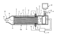
- the reducing agent injection device 100 of the present embodiment controls the electric heating of the honeycomb structure 1 and the spraying of the urea aqueous solution by the electronic control device 31.
- the electronic control device 31 is preferably connected to a power source (not shown).
- the voltage of the power supply is preferably 12 to 200V.
- the urea aqueous solution is supplied to the reducing agent injection device 100 from the urea aqueous solution storage tank 32. It is preferable that the urea aqueous solution storage tank 32 and the urea aqueous solution introduction port 8 of the reducing agent injection device 100 are connected by a pipe 33 through which the urea aqueous solution passes.
- the piping 33 has a heating function (not shown) so that urea aqueous solution can be heated.
- Examples of the heating function of the pipe 33 include a structure in which a heat medium circulates in the jacket, and an electric heating device.
- the outer cylinder 4 is preferably provided with two connectors 6 for connecting wiring from the electronic control device 31 (power source).
- honeycomb structure 1 In the reducing agent injection device 100 of the present embodiment, the honeycomb structure 1 includes the honeycomb structure portion 11 and the pair of electrodes 12 and 12 as described above.
- an outer peripheral wall 17 is disposed outside the partition wall 15.
- the material of the partition walls 15 and the outer peripheral wall 17 is preferably ceramic.
- the material of the partition wall 15 and the outer peripheral wall 17 is mainly composed of “silicon-silicon carbide composite material”, “silicon carbide” or the like.
- the main component is a “silicon-silicon carbide composite material”.
- silicon-silicon carbide composite material a plurality of silicon carbide particles are preferably bonded by metallic silicon.
- the “silicon carbide” is formed by sintering silicon carbide particles.
- main component means a component contained in 90% by mass or more.
- the electrical resistivity of the honeycomb structure portion 11 is preferably 0.01 to 500 ⁇ cm, and more preferably 0.1 to 200 ⁇ cm.
- the honeycomb structure honeycomb structure part
- the above electrical resistivity is preferable in order to cause the honeycomb structure 1 (honeycomb structure portion 11) to generate heat at 160 to 600 ° C. using a power source having a voltage of 12 to 200V.
- the electrical resistivity of the honeycomb structure part is a value at 25 ° C.
- the electrical resistivity of the honeycomb structure part is a value measured by a four-terminal method.
- Honeycomb structure body 11 the surface area per unit volume, is preferably 5 cm 2 / cm 3 or more, more preferably 8 ⁇ 45cm 2 / cm 3, particularly preferably 20 ⁇ 40cm 2 / cm 3. If it is less than 5 cm 2 / cm 3 , the contact area with the urea water becomes small, so that the treatment speed of the urea aqueous solution, that is, the generation amount (generation speed) of ammonia may decrease.
- the surface area of the honeycomb structure portion is the area of the surface of the partition walls of the honeycomb structure portion.
- the thickness of the partition wall 15 is preferably 0.06 to 1.5 mm, and more preferably 0.10 to 0.80 mm. If it is thicker than 1.5 mm, the pressure loss increases, and the treatment rate of the urea aqueous solution, that is, the generation amount (generation rate) of ammonia may decrease. If it is thinner than 0.06 mm, it may be destroyed by thermal shock caused by energization.
- the partition wall thickness is “the portion where the distance between the cells is the shortest (the portion where the partition wall is the thinnest)”. It means the thickness of the partition wall.
- the cell density is preferably 7 to 140 cells / cm 2, more preferably 15 to 120 cells / cm 2 . If it is less than 7 cells / cm 2 , the contact area with the urea water becomes small, so that the treatment rate of the urea aqueous solution, that is, the generation amount (generation rate) of ammonia may decrease. If it is greater than 140 cells / cm 2 , the pressure loss increases and the treatment rate of the urea aqueous solution, that is, the generation amount (generation rate) of ammonia may decrease.
- the reducing agent injection device of the present invention has a plugging portion 43 at “the end on the first end face 13 side of a part of the cells 16 of the honeycomb structure portion 42”.
- Fig. 4 is a plan view schematically showing an end face (first end face 13) of a honeycomb structure 41 constituting another embodiment of the reducing agent injection device of the present invention.
- the material of the plugging portion 43 is preferably the same as the material of the partition walls, but may be other materials.
- Size of the honeycomb structure 1 is preferably an area of the first end face 13 (second end surface 14) is 50 ⁇ 10000 mm 2, further preferably 100 ⁇ 8000mm 2.
- the shape of the cell 16 in a cross section orthogonal to the extending direction of the cell 16 is preferably a circle, an ellipse, a rectangle, a hexagon, an octagon, or a combination thereof.
- the shape of the cell 16 in a cross section (first end face) perpendicular to the extending direction of the cell 16 is circular.
- Each of the pair of electrode portions 12 and 12 is formed in a strip shape extending in the extending direction of the cells 16 of the honeycomb structure portion 11. Furthermore, it is preferable that the electrode portion 12 is formed wide so as to extend in the circumferential direction of the honeycomb structure portion 11. Further, in the cross section orthogonal to the extending direction of the cells 16, one electrode portion 12 in the pair of electrode portions 12, 12 is It is arranged on the opposite side across the center. Thereby, when a voltage is applied between the pair of electrode portions 12, 12, it is possible to suppress an uneven current flowing in the honeycomb structure portion 11. And thereby, the bias
- the electrode part 12 has the same main component as the main component of the partition wall 15 and the outer peripheral wall 17. Further, it is more preferable that the material of the electrode portion 12 has an electrical resistivity adjusted to a desired value.
- the electrical resistivity of the electrode portion 12 is preferably 0.0001 to 100 ⁇ cm, and more preferably 0.001 to 50 ⁇ cm. By setting the electrical resistivity of the electrode portion 12 in such a range, the pair of electrode portions 12 and 12 effectively serve as electrodes in the pipe through which high-temperature exhaust gas flows.
- the electrical resistivity of the electrode portion 12 is preferably lower than the electrical resistivity of the honeycomb structure portion 11.
- the electrical resistivity of an electrode part is a value in 400 degreeC.
- the electrical resistivity of an electrode part is the value measured by the four probe method.
- the porosity and average pore diameter of the electrode part 12 can be appropriately determined according to the application and so as to obtain a desired electrical resistivity.
- the electrode terminal protrusion 18 for connecting the electric wiring from the outside may be provided in each of the electrode parts 12 and 12.
- the material of the electrode terminal protrusion 18 may be a conductive ceramic or a metal.
- the material of the electrode terminal protrusion 18 is preferably the same as that of the electrode 12.
- a urea hydrolysis catalyst is supported on the honeycomb structure 11. Thereby, ammonia can be efficiently generated from urea.
- the urea hydrolysis catalyst include aluminum oxide.
- the urea spray device 2 is preferably a solenoid type, an ultrasonic type, a piezoelectric actuator type, or an atomizer type, and more preferably a solenoid type, an ultrasonic type, or a piezoelectric actuator type.
- the urea aqueous solution can be sprayed in a mist form.
- a solenoid type, ultrasonic type, or piezoelectric actuator type is used, the urea aqueous solution can be sprayed in a mist form without using air. Therefore, in the honeycomb structure, it is not necessary to heat up to the air used for urea injection, and the amount of energy to be heated can be reduced.
- the size (diameter) of the droplet of the urea aqueous solution sprayed from the urea spraying device is preferably 0.3 mm or less. If it is larger than 0.3 mm, it may be difficult to vaporize when receiving heat from the honeycomb structure 1.
- the urea spray device 2 is preferably provided with a urea aqueous solution inlet 8 for introducing a urea aqueous solution into the urea spray device 2.
- a solenoid-type urea spraying device is a device that sprays an aqueous urea solution in a mist form by “vibration of a solenoid” or “front and back movement of a piston by an electric field using a solenoid”.
- the ultrasonic urea spraying device is a device that sprays an aqueous urea solution in a mist form by ultrasonic vibration.
- a piezoelectric actuator type urea spraying device is a device that sprays an aqueous urea solution in a mist form by vibration of a piezoelectric element.
- An atomizer type urea spraying device is a device that sprays the liquid by spraying “liquid sucked into the opening at the tip of the tube” in a mist state while sucking up the liquid with a tube. Further, the atomizer type urea spraying device may be a device in which a plurality of small openings are formed at the tip of the nozzle and the liquid is sprayed in a mist form from the openings.
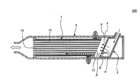
- the urea aqueous solution is sprayed from the urea spray device 2 toward the first end face 13 of the honeycomb structure 1. That is, in the urea spraying device 2, it is preferable that the spraying direction of the urea aqueous solution (the direction in which the droplets are ejected) face the first end face 13 of the honeycomb structure 1.
- the “spraying direction of the urea aqueous solution from the urea spraying device” is “spraying direction ⁇ ” (see FIG. 5), and “the direction in which ammonia passes through the cells of the honeycomb structure portion” is “cell direction ⁇ . (See FIG. 5).
- the angle ⁇ (see FIG. 5) between the “spray direction ⁇ ” and the “cell direction ⁇ ” is preferably 60 ° or less, more preferably 5 to 60 °, and particularly preferably 30 to 50 °.
- the angle ⁇ is preferably 60 ° or less, more preferably 5 to 60 °, and particularly preferably 30 to 50 °.
- FIG. 5 is a schematic view showing a cross section of still another embodiment (reducing agent injection device 200) of the reducing agent injection device of the present invention.
- the urea aqueous solution sprayed from the urea spraying apparatus 2 becomes easier to contact the partition in the cell.
- the method for manufacturing a honeycomb structure preferably includes a honeycomb molded body manufacturing process, a honeycomb dried body manufacturing process, a honeycomb body manufacturing process with an unfired electrode, and a honeycomb structure manufacturing process.
- the honeycomb molded body manufacturing process is a process of manufacturing a honeycomb molded body having partition walls that partition and form “a plurality of cells extending from one end surface serving as a fluid flow path to the other end surface” by extruding a forming raw material.
- the forming raw material preferably contains a ceramic raw material and an organic binder.
- the honeycomb dried body production step is preferably a step of drying the honeycomb formed body to produce a honeycomb dried body.
- a slurry for electrode formation containing a ceramic raw material and water is applied to the side surface of the dried honeycomb body and dried to form unfired electrodes. It is preferable that it is the process of producing a body.
- the honeycomb structure production step is preferably a step of producing a honeycomb structure by firing a honeycomb body with an unfired electrode.
- honeycomb molded body manufacturing process In the honeycomb formed body production step, it is preferable to produce a honeycomb formed body by extruding a forming raw material.
- the forming raw material preferably contains a ceramic raw material and an organic binder.
- the forming raw material preferably contains a surfactant, a sintering aid, a pore former, water and the like in addition to the ceramic raw material and the organic binder.
- the forming raw material can be produced by mixing these raw materials.
- the ceramic raw material in the forming raw material is “ceramic” or “raw material that becomes ceramic upon firing”. In any case, the ceramic raw material becomes ceramic after firing.
- the ceramic raw material in the forming raw material is preferably composed mainly of metal silicon and silicon carbide particles (silicon carbide powder), or composed mainly of silicon carbide particles (silicon carbide powder). Thereby, the obtained honeycomb structure becomes conductive.
- the metal silicon is also preferably metal silicon particles (metal silicon powder). Further, “mainly composed of metal silicon and silicon carbide particles” means that the total mass of metal silicon and silicon carbide particles is 90% by mass or more of the whole (ceramic raw material). Examples of components other than the main component contained in the ceramic raw material include SiO 2 , SrCO 3 , Al 2 O 3 , MgCO 3 , cordierite and the like.
- silicon carbide When silicon carbide is used as the main component of the ceramic raw material, the silicon carbide is sintered by firing. Further, when metal silicon and silicon carbide particles are used as the main component of the ceramic raw material, the silicon carbide as an aggregate can be bonded to each other by firing using the metal silicon as a binder.
- the mass of the metal silicon particles is larger than the total mass of the silicon carbide particles and the metal silicon particles. It is preferably 10 to 40% by mass.
- the average particle diameter of the silicon carbide particles is preferably 10 to 50 ⁇ m, more preferably 15 to 35 ⁇ m.
- the average particle diameter of the metal silicon particles is preferably from 0.1 to 20 ⁇ m, more preferably from 1 to 10 ⁇ m.
- the average particle diameter of the silicon carbide particles and the metal silicon particles is a value measured by a laser diffraction method.
- organic binder examples include methyl cellulose, glycerin, hydroxypropyl methyl cellulose and the like.
- the organic binder one type of organic binder or a plurality of types of organic binders may be used.
- the content of the organic binder is preferably 5 to 10 parts by mass when the total mass of the ceramic raw materials is 100 parts by mass.
- the surfactant ethylene glycol, dextrin and the like can be used.
- the surfactant one type of surfactant or a plurality of types of surfactants may be used.
- the content of the surfactant is preferably 0.1 to 2.0 parts by mass when the total mass of the ceramic raw materials is 100 parts by mass.
- the sintering aid SiO 2 , SrCO 3 , Al 2 O 3 , MgCO 3 , cordierite and the like can be used.
- a sintering aid one kind of sintering aid may be used, or a plurality of kinds of sintering aids may be used.
- the content of the sintering aid is preferably 0.1 to 3 parts by mass when the total mass of the ceramic raw materials is 100 parts by mass.
- the pore former is not particularly limited as long as it forms pores after firing, and examples thereof include graphite, starch, foamed resin, water absorbent resin, silica gel and the like.
- the pore former one type of pore former may be used, or a plurality of types of pore formers may be used.
- the pore former content is preferably 0.5 to 10 parts by mass when the total mass of the ceramic raw materials is 100 parts by mass.
- the content of water is preferably 20 to 60 parts by mass when the total mass of the ceramic raw materials is 100 parts by mass.
- a clay When extruding the forming raw material, it is preferable to first knead the forming raw material to form a clay.
- molding raw material and forming a clay For example, the method of using a kneader, a vacuum clay kneader, etc. can be mentioned.
- clay is also an aspect of the forming raw material.
- honeycomb formed body has a porous partition wall that forms “a plurality of cells extending from a first end surface that is a fluid flow path end surface to a fluid inflow side end surface to a second end surface that is a fluid outflow side end surface”. It is what you have.
- the formed honeycomb body has an outer peripheral wall located at the outermost periphery. The partition walls of the honeycomb formed body are undried and unfired partition walls.
- honeycomb dry body manufacturing process is preferably a step of drying the obtained honeycomb formed body to produce a honeycomb dried body. Drying conditions are not particularly limited, and known conditions can be used. For example, it is preferable to dry at 80 to 120 ° C. for 0.5 to 5 hours.
- the honeycomb formed body can be dried using an electric furnace, a gas furnace, a microwave heating furnace, a high frequency dielectric heating furnace, or the like.
- the honeycomb body with unfired electrodes is preferably formed by forming a wide rectangular unfired electrode that extends in a strip shape in the cell extending direction and also extends in the circumferential direction on the dried honeycomb body.
- the circumferential direction is a direction along the side surface of the dried honeycomb body in a cross section orthogonal to the cell extending direction.
- the electrode forming slurry used in the process for producing a honeycomb body with a non-fired electrode contains a ceramic raw material and water, and in addition, it preferably contains a surfactant, a pore former, water and the like.
- the ceramic raw material it is preferable to use a ceramic raw material used when a honeycomb formed body is produced.
- the main components of the ceramic raw material used in manufacturing the honeycomb formed body are silicon carbide particles and metal silicon
- the metal silicon particles with respect to the sum of the mass of the silicon carbide particles and the mass of the metal silicon particles
- the mass is preferably 20 to 50% by mass.
- the average particle size of the silicon carbide particles is preferably 10 to 100 ⁇ m, more preferably 15 to 75 ⁇ m.
- the average particle diameter of the metal silicon particles is preferably from 0.1 to 20 ⁇ m, more preferably from 1 to 10 ⁇ m.
- organic binder examples include methyl cellulose, glycerin, hydroxypropyl methyl cellulose and the like.
- the organic binder one type of organic binder or a plurality of types of organic binders may be used.
- the content of the organic binder is preferably 0.1 to 2 parts by mass when the total mass of the ceramic raw materials is 100 parts by mass.
- the surfactant ethylene glycol, dextrin and the like can be used.
- the surfactant one type of surfactant or a plurality of types of surfactants may be used.
- the content of the surfactant is preferably 5 to 15 parts by mass when the total mass of the ceramic raw materials is 100 parts by mass.
- the pore former is not particularly limited as long as it forms pores after firing, and examples thereof include graphite, starch, foamed resin, water absorbent resin, silica gel and the like.
- the pore former one type of pore former may be used, or a plurality of types of pore formers may be used.
- the pore former content is preferably 0.5 to 10 parts by mass when the total mass of the ceramic raw materials is 100 parts by mass.
- the water content is preferably 25 to 65 parts by mass when the total mass of the ceramic raw materials is 100 parts by mass.
- the method of applying the electrode forming slurry to the side surface of the dried honeycomb body is not particularly limited. For example, it can be applied using a brush, or can be applied using a printing technique.
- the viscosity of the electrode forming slurry is preferably 500 Pa ⁇ s or less, more preferably 10 to 200 Pa ⁇ s at 20 ° C. If it exceeds 500 Pa ⁇ s, it may be difficult to apply the electrode-forming slurry to the side surface of the honeycomb dried body.
- the electrode forming slurry After applying the electrode forming slurry to the dried honeycomb body, it is preferable to dry the electrode forming slurry to form a non-fired electrode (honeycomb-attached honeycomb body).
- the drying temperature is preferably 80 to 120 ° C.
- the drying time is preferably 0.1 to 5 hours.
- honeycomb structure manufacturing process is a process of manufacturing a honeycomb structure by firing an unfired honeycomb body with an electrode.
- Calcination conditions can be appropriately determined depending on the type of ceramic raw material used for manufacturing the honeycomb formed body and the ceramic raw material used for the electrode forming slurry.
- the firing conditions may be as follows: preferable. That is, it is preferable to heat at 2300 to 2700 ° C. for 0.5 to 5 hours in an inert atmosphere such as argon.
- the firing conditions are as follows: It is preferable to do so. That is, it is preferable to heat at 1425 to 1500 ° C. for 0.5 to 5 hours in an inert atmosphere such as argon.
- the firing method is not particularly limited, and firing can be performed using an electric furnace, a gas furnace, or the like.
- Pre-baking is preferably performed at 400 to 500 ° C. for 0.5 to 20 hours in an air atmosphere.
- Pre-baking and baking methods are not particularly limited, and pre-baking and baking can be performed using an electric furnace, a gas furnace, or the like.
- the outer cylinder is preferably formed by forming a material such as stainless steel into a cylindrical shape.
- the honeycomb structure is preferably fixed in the outer tube by an insulating holding portion. Further, when there is a portion (space) where the insulating holding portion is not disposed between the honeycomb structure and the outer cylinder, it is preferable to fill the insulating member.
- a solenoid type, ultrasonic type, piezoelectric actuator type, or atomizer type is preferably used.
- the solenoid type, ultrasonic type, piezoelectric actuator type, or atomizer type urea spraying device a known one can be used.
- the usage method of the reducing agent injection device 100 (see FIG. 1) of the present embodiment is as follows.
- the reducing agent injection device 100 is capable of hydrolyzing urea in the supplied urea aqueous solution and injecting ammonia by supplying the urea aqueous solution a1.
- the urea aqueous solution is a raw material for generating ammonia. More specifically, the honeycomb structure 1 is energized, the honeycomb structure 1 is heated (heated), the urea aqueous solution a1 is supplied to the urea spray device 2, and the urea spray device 2 supplies the urea spray space 3 in the urea spray space 3. It is preferable to spray a mist-like urea aqueous solution.
- urea aqueous solution from the urea spraying device 2 it is preferable to spray toward the first end face 13 of the honeycomb structure 1.
- the atomized urea aqueous solution sprayed in the urea spray space 3 (the urea aqueous solution a2 sprayed from the urea spray device 2) is heated by the honeycomb structure 1 and evaporated. Since the pressure in the urea spray space 3 increases due to the evaporation of the urea aqueous solution, urea and water enter the cells 16 of the honeycomb structure 1 from the first end face 13. Then, urea supplied into the cells 16 is hydrolyzed by the temperature of the heated honeycomb structure 1 to generate ammonia b.
- the generated ammonia b is injected from the injection port 23 of the outer cylinder 4, whereby the ammonia b of the reducing agent injection device 100 is injected. Since the pressure in the urea spray space 3 is rising, the injection of ammonia from the injection port is promoted.
- the supply amount of the urea aqueous solution is preferably 1.0 to 2.0 in an equivalent ratio with respect to the nitrogen oxide amount contained in the exhaust gas.
- the equivalent ratio is 1.0 or less, the amount of nitrogen oxides discharged without purification may increase. If the equivalent ratio exceeds 2.0, there is a possibility that exhaust gas is likely to be discharged in a state where ammonia is mixed in the exhaust gas.
- the urea aqueous solution is preferably a 10-40% by weight urea aqueous solution. If it is lower than 10% by mass, it is necessary to spray a large amount of urea water for NO X reduction, and the amount of electric power used in the honeycomb heater may increase. If it is higher than 40% by mass, urea may be solidified in a cold region.
- Adblue 32.5 mass% urea aqueous solution
- the temperature of the honeycomb structure 1 is preferably 160 ° C. or higher, more preferably 160 to 600 ° C., and particularly preferably 160 to 400 ° C. If it is lower than 160 ° C., urea may be difficult to hydrolyze. If it is higher than 600 ° C., ammonia may be burned and ammonia may not be supplied to the exhaust pipe. Moreover, it is preferable that the temperature of the honeycomb structure 1 is 360 ° C. or higher because sulfur compounds such as ammonium hydrogen sulfate and ammonium sulfate deposited on the reducing agent injection device 100 can be removed.
- the maximum voltage applied to the honeycomb structure 1 is preferably 12 to 200 V, more preferably 12 to 100 V, and particularly preferably 12 to 48 V. If it is lower than 12 V, it may be difficult to raise the temperature of the honeycomb structure 1. When the voltage is higher than 200 V, an apparatus for boosting the voltage is expensive, which is not preferable.
- the spray amount of the urea aqueous solution and the temperature of the honeycomb structure 1 are preferably controlled (set to appropriate values) by the electronic control device 31 (see FIG. 2). Moreover, it is preferable to calculate the temperature from the resistance value of the honeycomb structure and to control the temperature of the honeycomb structure so that the calculated temperature becomes a desired temperature.
- Exhaust gas treatment device 300 One embodiment (exhaust gas treatment device 300) of the exhaust gas treatment device of the present invention is disposed on the exhaust pipe 51, the reducing agent injection device 100, and "downstream of the exhaust pipe 51 from the position where ammonia is injected".
- the SCR catalyst 52 is provided.
- the reducing agent injection device 100 is for injecting ammonia into the exhaust pipe 51.
- the exhaust pipe 51 is a pipe through which “exhaust gas c containing NO X ” flows.
- Exhaust pipe 51 is a pipe through which (exhaust gas c containing NO X) exhaust gas discharged from an engine or the like, in this, the exhaust gas and ammonia are mixed.
- size of the exhaust pipe 51 is not specifically limited, According to exhaust systems, such as an engine which attaches the exhaust gas processing apparatus 300 of this embodiment, it can determine suitably.
- the length of the exhaust pipe 51 in the gas flow direction is not particularly limited, but is a length that allows the distance between the reducing agent injection device 100 and the SCR catalyst 52 to be an appropriate distance. Is preferred. Further, the length of the exhaust pipe 51 in the gas flow direction is preferably a length that can be mounted in a narrow space such as an automobile. Regarding the distance between the reducing agent injection device 100 and the SCR catalyst 52, the gaseous ammonia is supplied to improve the mixing state with the exhaust gas. It can be shorter than the “injector (urea injection device)”.
- the material of the exhaust pipe 51 is not particularly limited, but it is preferable that the exhaust pipe 51 is not easily corroded by exhaust gas.
- As a material of the exhaust pipe 51 for example, stainless steel is preferable.
- the reducing agent injection device 100 is a reducing agent injection device of the present invention.
- the reducing agent injection device 100 is attached to the exhaust pipe 51 and injects ammonia into the exhaust pipe 51. By injecting ammonia into the exhaust pipe 51 from the reducing agent injection device 100, a mixed gas d of ammonia and exhaust gas is generated in the exhaust pipe 51.
- the exhaust gas treatment apparatus 300 of the present embodiment includes the SCR catalyst 52 disposed “on the downstream side of the exhaust pipe 51 from the position where ammonia is injected”.
- the SCR catalyst is preferably arranged on the downstream side of the exhaust pipe 51 in the state of a catalyst body (the SCR catalyst is supported on the ceramic honeycomb structure).
- SCR catalyst examples include vanadium catalysts and zeolite catalysts.
- the SCR catalyst 52 When the SCR catalyst 52 is used as the catalyst body 53 supported on the honeycomb structure, the catalyst body 53 is stored in the storage container 54 and the storage container 54 is mounted on the downstream side of the exhaust pipe 51. It is preferable.
- the honeycomb structure supporting the SCR catalyst is not particularly limited, and a known “ceramic honeycomb structure supporting the SCR catalyst” can be used.
- a filter for collecting particulate matter in the exhaust gas is disposed on the upstream side of the exhaust pipe 51.
- the filter for collecting the particulate matter include a honeycomb-shaped ceramic diesel particulate filter (DPF).
- DPF honeycomb-shaped ceramic diesel particulate filter
- an oxidation catalyst for removing hydrocarbons and carbon monoxide in the exhaust gas is disposed on the upstream side of the exhaust pipe 51.
- the oxidation catalyst is preferably in a state of being supported on a ceramic honeycomb structure.
- a noble metal such as platinum (Pt), palladium (Pd), rhodium (Rh) is preferably used.
- an ammonia removal catalyst for removing ammonia on the downstream side of the SCR catalyst.
- an ammonia removal catalyst for removing ammonia on the downstream side of the SCR catalyst.
- a noble metal such as platinum (Pt), palladium (Pd), rhodium (Rh) is preferably used.
- Exhaust gas treatment method uses an embodiment of the exhaust gas treatment device of the present invention (exhaust gas treatment device 300) shown in FIG. b is injected and the mixed gas is reduced with an SCR catalyst.
- the exhaust gas c are those containing NO X.
- the mixed gas is “exhaust gas mixed with ammonia” and is a mixed gas d of ammonia and exhaust gas.
- the ammonia b is injected by the reducing agent injection device 100.
- the temperature of the honeycomb structure constituting the reducing agent injection device 100 is preferably 160 ° C. or higher, more preferably 160 to 600 ° C., and particularly preferably 160 to 400 ° C. If it is lower than 160 ° C., urea may be difficult to hydrolyze. If it is higher than 600 ° C., ammonia may be burned and ammonia may not be supplied to the exhaust pipe. In addition, it is preferable to intermittently perform the reducing agent injection device purification operation for removing the sulfur compound adhering to the reducing agent injection device by setting the temperature of the honeycomb structure to 360 ° C. or higher.
- the voltage applied to the honeycomb structure 1 is preferably 12 to 200V, more preferably 12 to 100V, and particularly preferably 12 to 48V. If it is lower than 12 V, it may be difficult to raise the temperature of the honeycomb structure 1. When the voltage is higher than 200 V, an apparatus for boosting the voltage is expensive, which is not preferable.
- the electronic control device 31 it is preferable to control the spray amount of the urea aqueous solution and the temperature (voltage to be applied) of the honeycomb structure 1 by the electronic control device 31 (see FIG. 2). Moreover, it is preferable to calculate the temperature from the resistance value of the honeycomb structure and to control the temperature of the honeycomb structure so that the calculated temperature becomes a desired temperature.
- the amount of ammonia injected from the reducing agent injection device 100 is preferably 1.0 to 2.0 in terms of an equivalent ratio with respect to the amount of nitrogen oxides contained in the exhaust gas.
- the equivalent ratio is 1.0 or less, the amount of nitrogen oxides discharged without purification may increase. If the equivalent ratio exceeds 2.0, there is a possibility that exhaust gas is likely to be discharged in a state where ammonia is mixed in the exhaust gas.
- Example 1 A reducing agent injection device as shown in FIG. 1 was produced. Specifically, it is as follows.
- Silicon carbide (SiC) powder and metal silicon (Si) powder were mixed at a mass ratio of 70:30 to prepare a ceramic raw material. Then, hydroxypropylmethylcellulose as a binder and a water-absorbing resin as a pore former were added to the ceramic raw material, and water was added to form a forming raw material. Then, the forming raw material was kneaded with a vacuum kneader to produce a columnar clay.
- the content of the binder was 7 parts by mass when the ceramic raw material was 100 parts by mass.
- the content of the pore former was 3 parts by mass when the ceramic raw material was 100 parts by mass.
- the water content was 42 parts by mass when the ceramic raw material was 100 parts by mass.
- the average particle diameter of the silicon carbide powder was 20 ⁇ m, and the average particle diameter of the metal silicon powder was 6 ⁇ m. Moreover, the average particle diameter of the pore former was 20 ⁇ m.
- the average particle diameters of silicon carbide, metal silicon and pore former are values measured by a laser diffraction method.
- the obtained columnar kneaded material was molded using an extruder to obtain a honeycomb molded body having a square cylindrical shape (a cylindrical shape having a square cross section perpendicular to the cell extending direction).
- the obtained honeycomb formed body was dried by high-frequency dielectric heating and then dried at 120 ° C. for 2 hours using a hot air dryer, and both end surfaces were cut by a predetermined amount.
- a silicon carbide (SiC) powder and a metal silicon (Si) powder were mixed at a mass ratio of 60:40 to produce a ceramic raw material for an electrode part.
- hydroxypropylmethylcellulose as a binder, glycerin as a humectant, and a surfactant as a dispersant were added to the ceramic raw material for the electrode part, and water was added and mixed.
- the mixture was kneaded to obtain an electrode part forming raw material.
- the content of the binder was 0.5 part by mass when the ceramic raw material for the electrode part was 100 parts by mass.
- the content of glycerin was 10 parts by mass when the electrode material ceramic raw material was 100 parts by mass.
- the content of the surfactant was 0.3 part by mass when the ceramic raw material for the electrode part was 100 parts by mass.
- the water content was 42 parts by mass when the electrode part ceramic raw material was 100 parts by mass.
- the average particle diameter of the silicon carbide powder was 52 ⁇ m, and the average particle diameter of the metal silicon powder was 6 ⁇ m.
- the average particle diameter of silicon carbide and metal silicon is a value measured by a laser diffraction method. The kneading was performed with a vertical stirrer.
- the electrode part forming raw material was applied in a strip shape on two parallel surfaces of the dried honeycomb molded body.
- the electrode part forming raw material is applied in a strip shape on one side surface of the “side surfaces having four planes (four side surfaces)” of the dried honeycomb molded body, and is applied to the “applied side surface”. It was applied in a strip shape on one parallel side.
- the shape (peripheral shape) of the electrode part forming raw material applied to the side surface of the honeycomb formed body was a rectangle.
- the electrode part forming raw material applied to the honeycomb formed body was dried.
- the drying conditions were 70 ° C.
- an electrode terminal protrusion forming member was obtained using the same member as the electrode forming material.
- the shape of the electrode terminal protrusion forming member was a cylinder of “8 mm ( ⁇ : diameter) ⁇ 10 mm (length)”. Two electrode terminal protrusion forming members were prepared.
- each of the two electrode terminal protrusion forming members was attached to each of the portions of the honeycomb formed body to which the electrode portion forming raw material was applied.
- the electrode terminal protrusion forming member was attached to the portion of the honeycomb formed body to which the electrode part forming raw material was applied using the electrode part forming raw material.
- “the honeycomb formed body on which the electrode part forming raw material was applied and the electrode terminal protrusion forming member was attached” was degreased, fired, and further oxidized to obtain a honeycomb structure.
- the degreasing conditions were 550 ° C. for 3 hours.
- the firing conditions were 1450 ° C. and 2 hours in an argon atmosphere.
- the conditions for the oxidation treatment were 1300 ° C. and 1 hour.
- the partition wall thickness of the obtained honeycomb structure was 0.152 mm, and the cell pitch was 1.11 mm.
- the surface area per unit volume of the honeycomb structure part was 31.1 cm 2 / cm 3 .
- the shape of the honeycomb structure was a cylindrical shape having a square bottom surface. One side of the bottom surface of the honeycomb structure was 30 mm.
- the length of the honeycomb structure in the cell extending direction was 45 mm.
- the electrical resistivity of the electrode part was 0.1 ⁇ cm, and the electrical resistivity of the honeycomb structure part was 1.4 ⁇ cm.
- the outer cylinder was made of stainless steel.
- the outer cylinder was formed into a cylindrical shape having an inlet side end portion which is one end portion and an outlet side end portion which is the other end portion.
- An injection port that is an opening for injecting ammonia gas was formed at the tip of the outlet side end of the outer cylinder.
- transduces urea aqueous solution was formed in the inlet side edge part of an outer cylinder.
- the honeycomb structure was inserted into the outer cylinder and fixed with an insulating holding member.
- the electrode terminal protrusions of the honeycomb structure and the connector of the outer cylinder were connected by electric wiring.
- a solenoid type urea spraying device was installed in the inlet side end of the outer cylinder to obtain a reducing agent injection device.
- the material of the insulating holding member was alumina.
- the angle between the spray direction of the urea spray device and the cell direction of the honeycomb structure was 0 °.
- a catalyst body was prepared by supporting an SCR catalyst on a honeycomb structure mainly composed of cordierite.
- SCR catalyst a zeolite having a noble metal supported thereon was used.
- the volume of the catalyst body was 4.0 liters.
- the partition wall thickness of the catalyst body was 0.15 mm, and the cell pitch of the catalyst body was 1.27 mm.
- the obtained reducing agent injection device was attached to the exhaust pipe, the catalyst body was inserted into the storage container, and the exhaust pipe and the storage container were connected to obtain an exhaust gas treatment apparatus as shown in FIG.
- exhaust gas treatment test An exhaust gas of a diesel engine having a displacement of 3.0 liters is introduced into an exhaust pipe of an exhaust gas treatment device, and the exhaust gas is treated by the exhaust gas treatment device. Then, SCR catalyst for measuring the concentration of NO X in the gas discharged from the supported catalyst. Concentration of NO X exhaust gas introduced into the exhaust pipe of the exhaust gas treatment device, and 400 ppm. The amount of the urea aqueous solution supplied to the reducing agent injection device is adjusted so that the amount of NO X (mole) in the exhaust gas and the amount of ammonia injected (mole) are the same.
- Example 1 An exhaust gas treatment device was produced in the same manner as in Example 1 except that the reducing agent injection device was not provided with a honeycomb structure. In the same manner as in Example 1, an “exhaust gas treatment test” was performed. The results are shown in Table 1.
- the exhaust gas purifying apparatus of the first embodiment it can be seen that a high NO X purification efficiency compared to the exhaust gas cleaner of Comparative Example 1.
- the difference is particularly large in the region where the exhaust gas temperature is low.
- the exhaust gas purifying device of Comparative Example 1 is not promoted hydrolysis to ammonia at low temperature, to become a state reducing agent is less, NO X purification efficiency is lowered.
- the urea spray space into which the urea aqueous solution is injected is heated by the honeycomb structure, so that hydrolysis of urea is promoted and ammonia enters the exhaust pipe. for introduction, to improve the NO X purification efficiency.
- ammonia could be generated and injected from the urea solution with a small amount of energy.
- the reducing agent injection device of the present invention can be suitably used to purify nitrogen oxides (NO x ) in exhaust gas discharged from various engines and the like.
Landscapes
- Chemical & Material Sciences (AREA)
- Engineering & Computer Science (AREA)
- Chemical Kinetics & Catalysis (AREA)
- Health & Medical Sciences (AREA)
- Combustion & Propulsion (AREA)
- Environmental & Geological Engineering (AREA)
- Mechanical Engineering (AREA)
- General Engineering & Computer Science (AREA)
- Analytical Chemistry (AREA)
- Biomedical Technology (AREA)
- General Chemical & Material Sciences (AREA)
- Oil, Petroleum & Natural Gas (AREA)
- Toxicology (AREA)
- Organic Chemistry (AREA)
- Materials Engineering (AREA)
- Exhaust Gas Treatment By Means Of Catalyst (AREA)
- Exhaust Gas After Treatment (AREA)
- Catalysts (AREA)
Abstract
Description
図1に示すように、本発明の還元剤噴射装置100の一実施形態は、ハニカム構造体1と、尿素水溶液を霧状に噴霧する尿素噴霧装置2とを備えるものである。ハニカム構造体1は、筒状のハニカム構造部11及びハニカム構造部11の側面に配設された一対の電極部12,12を有するものである。ハニカム構造部11は、「「流体の流路となり流体の流入側の端面である第1端面13から流体の流出側の端面である第2端面14まで延びる複数のセル16」を、区画形成する隔壁15」を有するものである。一対の電極部12,12のそれぞれが、ハニカム構造部11のセル16の延びる方向に延びる帯状に形成されている。セル16の延びる方向に直交する断面において、一対の電極部12,12における一方の電極部12が、一対の電極部12,12における他方の電極部12に対して、ハニカム構造部11の中心を挟んで反対側に配設されている。本実施形態の還元剤噴射装置100は、尿素噴霧装置2から噴霧された尿素水溶液a2が、ハニカム構造部11の第1端面13からセル16内に供給される。そして、セル16内に供給された尿素水溶液中の尿素が、通電加熱されたハニカム構造部11内で加熱されて加水分解されて、アンモニア(還元剤)が生成する。そして、アンモニアbが、第2端面14からハニカム構造部11の外側に排出され、当該アンモニアbが外部に噴射される。図1は、本発明の還元剤噴射装置100の一実施形態の断面(ハニカム構造部11のセル16の延びる方向に平行な断面)を示す模式図である。
本実施形態の還元剤噴射装置100において、ハニカム構造体1は、上記のように、ハニカム構造部11及び一対の電極12,12を備えるものである。
尿素噴霧装置2は、ソレノイド式、超音波式、圧電アクチュエータ式、又はアトマイザー式であることが好ましく、ソレノイド式、超音波式、又は圧電アクチュエータ式であることが更に好ましい。これらを用いることにより、尿素水溶液を霧状に噴霧することができる。また、これらの中でも、ソレノイド式、超音波式、又は圧電アクチュエータ式を用いると、空気を使用せずに尿素水溶液を霧状に噴霧することができる。そのため、ハニカム構造体では尿素噴射に用いる空気まで加熱する必要が無くなり加熱するエネルギー量を少なくすることができる。更に、噴射空気が無いことで、噴射体積が減少しハニカム構造体を「霧状の尿素水溶液」が通過する速度を低下させることが可能であるため、加水分解に必要な反応時間を長く取ることが可能となる。尿素噴霧装置から噴霧される尿素水溶液の液滴の大きさ(直径)は、0.3mm以下であることが好ましい。0.3mmより大きいと、ハニカム構造体1から熱を受けた時に、気化し難くなることがある。
(2-1)ハニカム構造体の製造;
ハニカム構造体がセラミック製の場合、ハニカム構造体の製造方法は、以下のような製造方法であることが好ましい。ハニカム構造体の製造方法は、ハニカム成形体作製工程と、ハニカム乾燥体作製工程と、未焼成電極付きハニカム体作製工程と、ハニカム構造体作製工程とを有するものであることが好ましい。ハニカム成形体作製工程は、成形原料を押出成形して、「流体の流路となる一方の端面から他方の端面まで延びる複数のセル」を区画形成する隔壁を有するハニカム成形体を作製する工程であることが好ましい。成形原料は、セラミック原料及び有機バインダを含有するものであることが好ましい。ハニカム乾燥体作製工程は、ハニカム成形体を乾燥してハニカム乾燥体を作製する工程であることが好ましい。未焼成電極付きハニカム体作製工程は、ハニカム乾燥体の側面に、セラミック原料と水とを含有する電極形成用スラリーを塗布し、乾燥させて、未焼成電極を形成して、未焼成電極付きハニカム体を作製する工程であることが好ましい。ハニカム構造体作製工程は、未焼成電極付きハニカム体を焼成してハニカム構造体を作製する工程であることが好ましい。
ハニカム成形体作製工程においては、成形原料を押出成形して、ハニカム成形体を作製することが好ましい。成形原料は、セラミック原料及び有機バインダを含有するものであることが好ましい。成形原料には、セラミック原料及び有機バインダ以外に、界面活性剤、焼結助剤、造孔材、水等が含有されることが好ましい。成形原料は、これらの原料を混合して作製することができる。
ハニカム乾燥体作製工程は、得られたハニカム成形体を乾燥させて、ハニカム乾燥体を作製する工程であることが好ましい。乾燥条件は、特に限定されず、公知の条件を用いることができる。例えば、80~120℃で、0.5~5時間乾燥させることが好ましい。ハニカム成形体の乾燥は、電気炉、ガス炉、マイクロ波加熱炉、高周波誘電加熱炉等を用いて行うことができる。
未焼成電極付きハニカム体作製工程は、まず、ハニカム乾燥体の側面に、セラミック原料と水とを含有する電極形成用スラリーを塗布することが好ましい。そして、その後、電極形成用スラリーを乾燥させて未焼成電極を形成して、未焼成電極付きハニカム体を作製することが好ましい。
ハニカム構造体作製工程は、未焼成電極付きハニカム体を焼成してハニカム構造体を作製する工程である。
外筒に、外部からの電気配線を繋ぐコネクターを取り付け、ハニカム構造体及び尿素噴霧装置を外筒に収納し、固定して還元剤噴射装置を作製することが好ましい。
本実施形態の還元剤噴射装置100(図1を参照)の使用方法は、以下の通りである。
本発明の排ガス処理装置の一実施形態(排ガス処理装置300)は、排気管51と、還元剤噴射装置100と、「排気管51の、アンモニアが噴射される位置より下流側」に配置されたSCR触媒52とを備えるものである。還元剤噴射装置100は、排気管51内にアンモニアを噴射するものである。排気管51は、「NOXを含有する排ガスc」を流す配管である。
本発明の排ガス処理方法の一実施形態は、図6に示される本発明の排ガス処理装置の一実施形態(排ガス処理装置300)を用いて、排気管51に排ガスcを流し、排ガスcにアンモニアbを噴射し、混合ガスをSCR触媒で還元処理する方法である。これにより、NOX除去後の排ガスeが得られる。上記排ガスcは、NOXを含有するものである。上記混合ガスは、「アンモニアが混入した排ガス」であり、アンモニアと排ガスとの混合ガスdである。アンモニアbの噴射は、還元剤噴射装置100によって行う。
図1に示されるような、還元剤噴射装置を作製した。具体的には、以下の通りである。
排気量3.0リットルのディーゼルエンジンの排ガスを、排ガス処理装置の排気管に導入し、排ガス処理装置によって排ガスの処理を行う。そして、SCR触媒が担持された触媒体から排出されたガス中のNOX濃度を測定する。排ガス処理装置の排気管に導入される排ガスのNOX濃度は、400ppmとする。還元剤噴射装置に供給する尿素水溶液の量は、排ガス中のNOX量(モル)と噴射されるアンモニアの量(モル)とが同じ量となるように、調整する。試験の際には、排ガス温度を表1に示されるように変化させながら、各温度において触媒体から排出されるガス中のNOX濃度を測定する。排出されるガス中のNOX濃度は、当該NOX濃度が一定になったときの濃度とする。そして、排ガス処理装置の排気管に導入される排ガスのNOX濃度と、触媒体から排出されるガス中のNOX濃度とから、NOX浄化効率を求める。測定時には、ハニカム構造体に最大48Vの電圧を印加し、360℃の温度を維持する。

還元剤噴射装置にハニカム構造体を備えなかった以外は、実施例1と同様にして、排ガス処理装置を作製した。実施例1の場合と同様にして、「排ガス処理試験」を行った。結果を表1に示す。
Claims (14)
- 流体の流路となり流体の流入側の端面である第1端面から流体の流出側の端面である第2端面まで延びる複数のセルを、区画形成する隔壁を有する筒状のハニカム構造部、及び前記ハニカム構造部の側面に配設された一対の電極部を有するハニカム構造体と、
尿素水溶液を霧状に噴霧する尿素噴霧装置とを備え、
前記一対の電極部のそれぞれが、前記ハニカム構造部のセルの延びる方向に延びる帯状に形成され、前記セルの延びる方向に直交する断面において、前記一対の電極部における一方の前記電極部が、前記一対の電極部における他方の前記電極部に対して、前記ハニカム構造部の中心を挟んで反対側に配設され、
前記尿素噴霧装置から噴霧された前記尿素水溶液が、前記ハニカム構造部の前記第1端面から前記セル内に供給され、前記セル内に供給された前記尿素水溶液中の尿素が、通電加熱された前記ハニカム構造部内で加熱されて加水分解されて、アンモニアが生成し、前記アンモニアが前記第2端面から前記ハニカム構造部の外側に排出され、前記アンモニアが外部に噴射される還元剤噴射装置。 - 前記ハニカム構造部の前記第1端面と前記尿素噴霧装置との間に、尿素噴霧空間が形成された請求項1に記載の還元剤噴射装置。
- 前記ハニカム構造体部の電気抵抗率が0.01~500Ωcmである請求項1又は2に記載の還元剤噴射装置。
- 前記ハニカム構造部が、珪素-炭化珪素複合材料又は炭化珪素を主成分とする請求項1~3のいずれかに記載の還元剤噴射装置。
- 前記ハニカム構造体に、尿素加水分解触媒が担持されている請求項1~4のいずれかに記載の還元剤噴射装置。
- 前記尿素水溶液が、前記尿素噴霧装置から、前記ハニカム構造体の前記第1端面に向かって噴霧され、
前記尿素噴霧装置からの前記尿素水溶液の噴霧方向と、前記ハニカム構造部の前記セルの延びる方向に平行な方向であり且つ前記尿素噴霧装置から前記ハニカム構造体の前記第1端面に向かう方向との角度が、5~60°である請求項1~5のいずれかに記載の還元剤噴射装置。 - 前記ハニカム構造部の単位体積当たりの表面積が、5cm2/cm3以上である請求項1~6のいずれかに記載の還元剤噴射装置。
- 前記ハニカム構造部の一部の前記セルの、前記第1端面側の端部に、目封止部を有する請求項1~7のいずれかに記載の還元剤噴射装置。
- 前記尿素噴射措置が、ソレノイド式、圧電アクチュエータ式、超音波式、又はアトマイザー式である請求項1~8のいずれかに記載の還元剤噴射装置。
- NOXを含有する排ガスを流す排気管と、
前記排気管内にアンモニアを噴射する請求項1~9のいずれかに記載の還元剤噴射装置と、
前記排気管の、前記アンモニアが噴射される位置より下流側に配置されたSCR触媒とを備えた排ガス処理装置。 - 請求項10に記載の排ガス処理装置を用いて、前記排気管にNOXを含有する排ガスを流し、前記排ガスにアンモニアを噴射し、前記アンモニアが混入した排ガスを前記SCR触媒で還元処理する排ガス処理方法。
- 前記ハニカム構造体の温度が160℃以上である請求項11に記載の排ガス処理方法。
- 前記ハニカム構造体の温度を360℃以上として前記還元剤噴射装置に付着した硫黄化合物を除去する還元剤噴射装置浄化操作を、断続的に行う請求項11又は12に記載の排ガス処理方法。
- 前記ハニカム構造体の抵抗値から温度を算出し、前記算出された温度が所望の温度になるように、前記ハニカム構造体の温度を制御する請求項11~13のいずれかに記載の排ガス処理方法。
Priority Applications (5)
| Application Number | Priority Date | Filing Date | Title |
|---|---|---|---|
| EP14770812.7A EP2977096B1 (en) | 2013-03-22 | 2014-03-18 | Reducing agent injection device, exhaust gas treatment device and exhaust gas treatment method |
| JP2015506806A JPWO2014148506A1 (ja) | 2013-03-22 | 2014-03-18 | 還元剤噴射装置、排ガス処理装置及び排ガス処理方法 |
| CN201480017393.5A CN105050692A (zh) | 2013-03-22 | 2014-03-18 | 还原剂喷射装置、废气处理装置以及废气处理方法 |
| US14/856,659 US9759106B2 (en) | 2013-03-22 | 2015-09-17 | Reducing agent injection device, exhaust gas treatment device and exhaust gas treatment method |
| US15/588,110 US20170241318A1 (en) | 2013-03-22 | 2017-05-05 | Reducing agent injection device, exhaust gas treatment device and exhaust gas treatment method |
Applications Claiming Priority (2)
| Application Number | Priority Date | Filing Date | Title |
|---|---|---|---|
| JP2013-060923 | 2013-03-22 | ||
| JP2013060923 | 2013-03-22 |
Related Child Applications (1)
| Application Number | Title | Priority Date | Filing Date |
|---|---|---|---|
| US14/856,659 Continuation US9759106B2 (en) | 2013-03-22 | 2015-09-17 | Reducing agent injection device, exhaust gas treatment device and exhaust gas treatment method |
Publications (1)
| Publication Number | Publication Date |
|---|---|
| WO2014148506A1 true WO2014148506A1 (ja) | 2014-09-25 |
Family
ID=51580183
Family Applications (1)
| Application Number | Title | Priority Date | Filing Date |
|---|---|---|---|
| PCT/JP2014/057385 Ceased WO2014148506A1 (ja) | 2013-03-22 | 2014-03-18 | 還元剤噴射装置、排ガス処理装置及び排ガス処理方法 |
Country Status (5)
| Country | Link |
|---|---|
| US (2) | US9759106B2 (ja) |
| EP (1) | EP2977096B1 (ja) |
| JP (2) | JPWO2014148506A1 (ja) |
| CN (2) | CN109012175A (ja) |
| WO (1) | WO2014148506A1 (ja) |
Cited By (9)
| Publication number | Priority date | Publication date | Assignee | Title |
|---|---|---|---|---|
| JP2017180298A (ja) * | 2016-03-30 | 2017-10-05 | 日本碍子株式会社 | 還元剤噴射装置、及び排ガス処理方法 |
| JP2017180299A (ja) * | 2016-03-30 | 2017-10-05 | 日本碍子株式会社 | 還元剤噴射装置、及び排ガス処理装置 |
| JP2017180295A (ja) * | 2016-03-30 | 2017-10-05 | 日本碍子株式会社 | 還元剤噴射装置、及び排ガス処理装置 |
| JP2019163760A (ja) * | 2018-03-20 | 2019-09-26 | 日本碍子株式会社 | 流体加熱部品、及び流体加熱部品複合体 |
| CN113167156A (zh) * | 2018-12-04 | 2021-07-23 | 日本碍子株式会社 | 还原剂喷射装置、废气处理装置及废气处理方法 |
| DE112019006084T5 (de) | 2018-12-06 | 2021-08-19 | Ngk Insulators, Ltd. | Reduktionsmittel-einspritzvorrichtung, abgasverarbeitungsvorrichtung und abgasverarbeitungsverfahren |
| DE112019006135T5 (de) | 2018-12-10 | 2021-08-19 | Ngk Insulators, Ltd. | Reduktionsmittel-Einspritzvorrichtung, Abgasverarbeitungsvorrichtung und Abgasverarbeitungsverfahren |
| US11310873B2 (en) | 2018-03-20 | 2022-04-19 | Ngk Insulators, Ltd. | Fluid heating component, and fluid heating component complex |
| WO2022097321A1 (ja) * | 2020-11-09 | 2022-05-12 | 日本碍子株式会社 | 還元剤生成装置の制御方法、排ガス浄化処理方法、還元剤生成システム及び排ガス浄化処理システム |
Families Citing this family (11)
| Publication number | Priority date | Publication date | Assignee | Title |
|---|---|---|---|---|
| US9617892B2 (en) * | 2015-07-22 | 2017-04-11 | Caterpillar Inc. | Method and apparatus to reduce urea deposits |
| CN105351050A (zh) * | 2015-12-04 | 2016-02-24 | 特威泰克环保技术(山东)有限公司 | 一种柴油车过滤器用氨气发生装置 |
| DE202016002697U1 (de) * | 2016-04-27 | 2017-07-28 | Tropinon Enterprises Ltd. | Vorrichtung zur hydrolytischen Erzeugung von Ammoniak |
| EP3333387B1 (en) * | 2016-12-12 | 2021-03-24 | Perkins Engines Company Limited | Injector deposit detection for scr injection system |
| DE112017008275T5 (de) * | 2017-12-15 | 2020-08-20 | Cummins Emission Solutions Inc. | Hochkonduktive Abgaskomponenten zur Ablagerungsvorbeugung & verminderung |
| US10888856B2 (en) * | 2018-04-13 | 2021-01-12 | Ngk Insulators, Ltd. | Honeycomb structure |
| JP7345405B2 (ja) * | 2019-05-30 | 2023-09-15 | 日本碍子株式会社 | 排ガス浄化装置用混合器、排ガス浄化装置及び排ガス浄化方法 |
| CN110685785B (zh) * | 2019-10-22 | 2021-08-20 | 燕山大学 | 一种超声复合型二次空气喷射系统及其控制方法 |
| CN113606020B (zh) * | 2021-07-16 | 2022-03-22 | 江苏伟博动力技术有限公司 | 一种废气净化用气液混合器 |
| JP7428176B2 (ja) | 2021-12-09 | 2024-02-06 | いすゞ自動車株式会社 | 排気構造およびインジェクタ取付部材 |
| KR102671528B1 (ko) * | 2022-01-20 | 2024-06-03 | 제주대학교 산학협력단 | 질소산화물의 촉매 환원 성능 향상을 위한 질소산화물 환원제 전처리 장치 및 이를 포함하는 질소산화물 저감 장치 |
Citations (11)
| Publication number | Priority date | Publication date | Assignee | Title |
|---|---|---|---|---|
| EP0487886A1 (de) * | 1990-11-29 | 1992-06-03 | MAN Nutzfahrzeuge Aktiengesellschaft | Verfahren und Vorrichtung zur selektiven katalytischen NOx-Reduktion in sauerstoffhaltigen Abgasen |
| JPH11125110A (ja) * | 1997-08-09 | 1999-05-11 | Man Nutzfahrzeuge Ag | 酸素を含む機関排気ガス中における触媒nox還元を行なう装置及び方法 |
| JP2005344597A (ja) * | 2004-06-02 | 2005-12-15 | Hitachi Ltd | エンジン用排気ガス処理装置 |
| JP2007327377A (ja) | 2006-06-07 | 2007-12-20 | Hitachi Ltd | 排気ガス浄化装置 |
| JP2009524765A (ja) | 2006-01-27 | 2009-07-02 | ピールブルク ゲゼルシャフト ミット ベシュレンクテル ハフツング | 内燃機関の排ガス中の窒素酸化物を還元するための装置 |
| JP2010506077A (ja) | 2006-10-02 | 2010-02-25 | エミテック ゲゼルシヤフト フユア エミツシオンス テクノロギー ミツト ベシユレンクテル ハフツング | 反応物を蒸発させるための装置および方法 |
| JP2010229978A (ja) * | 2009-03-30 | 2010-10-14 | Ngk Insulators Ltd | 通電加熱型ハニカム体の制御システム |
| JP2011078899A (ja) * | 2009-10-06 | 2011-04-21 | Ngk Insulators Ltd | 触媒担持フィルタ |
| JP2012197695A (ja) * | 2011-03-18 | 2012-10-18 | Hino Motors Ltd | 尿素水改質器及びこれを用いた排ガス浄化装置 |
| JP2012225284A (ja) * | 2011-04-21 | 2012-11-15 | Isuzu Motors Ltd | 排気ガス浄化システムと排気ガス浄化方法 |
| JP2012233443A (ja) * | 2011-05-02 | 2012-11-29 | Ngk Insulators Ltd | 排ガス浄化システム |
Family Cites Families (42)
| Publication number | Priority date | Publication date | Assignee | Title |
|---|---|---|---|---|
| JP3001281B2 (ja) | 1991-03-06 | 2000-01-24 | 日本碍子株式会社 | ハニカムモノリスヒータ |
| JP3058992B2 (ja) * | 1992-07-29 | 2000-07-04 | 日本碍子株式会社 | 多段ハニカムヒーター |
| JPH06248936A (ja) * | 1993-02-25 | 1994-09-06 | Zexel Corp | 燃焼排ガス浄化装置 |
| DE19510804A1 (de) * | 1995-03-24 | 1996-09-26 | Dornier Gmbh | Verfahren und Vorrichtung zur Stickoxidminderung in Abgasen von Verbrennungsmaschinen |
| JPH10231720A (ja) * | 1997-02-17 | 1998-09-02 | Hitachi Ltd | 自動車内燃機関の排ガス浄化触媒の再生方法 |
| ATE220943T1 (de) * | 1997-05-16 | 2002-08-15 | Siemens Ag | Verfahren und vorrichtung zur vernichtung von oxidischen schadstoffen in einem sauerstoffhaltigen abgas sowie damit betriebener motor |
| JPH1112510A (ja) | 1997-06-20 | 1999-01-19 | Hitachi Koki Co Ltd | ソリッドインク製造方法 |
| DE19903533A1 (de) * | 1999-01-29 | 2000-08-10 | Degussa | Verfahren zur selektiven katalytischen Reduktion von Stickoxiden in sauerstoffhaltigen Abgasen |
| KR100398099B1 (ko) * | 2000-12-29 | 2003-09-19 | 현대자동차주식회사 | 온도 rpm제어형 Urea-SCR 시스템 |
| DE10206028A1 (de) * | 2002-02-14 | 2003-08-28 | Man Nutzfahrzeuge Ag | Verfahren und Vorrichtung zur Erzeugung von Ammoniak |
| DE10257113A1 (de) * | 2002-12-05 | 2004-06-24 | Emitec Gesellschaft Für Emissionstechnologie Mbh | Partikelfalle mit beschichteter Faserlage |
| JP4262522B2 (ja) * | 2003-05-28 | 2009-05-13 | 株式会社日立ハイテクノロジーズ | エンジン用排気ガス処理装置および排気ガス処理方法 |
| JP5152227B2 (ja) * | 2003-11-19 | 2013-02-27 | 日本化成株式会社 | 尿素水 |
| KR100590953B1 (ko) * | 2003-12-17 | 2006-06-19 | 기아자동차주식회사 | 차량용 질소산화물 제거시스템의 유리아 공급장치 |
| DE102005031816A1 (de) | 2005-07-06 | 2007-01-18 | Emitec Gesellschaft Für Emissionstechnologie Mbh | Verfahren zur Reduzierung des Partikel- und Stickoxidanteils im Abgasstrom einer Verbrennungskraftmaschine und entsprechende Abgasaufbereitungseinheit |
| DE102005035554A1 (de) * | 2005-07-29 | 2007-02-01 | Emitec Gesellschaft Für Emissionstechnologie Mbh | Verfahren zur selektiven katalytischen Reduktion von Stickoxiden im Abgas einer Verbrennungskraftmaschine und Abgassystem |
| US20070048204A1 (en) * | 2005-09-01 | 2007-03-01 | Rahul Mital | Flash injector for NH3-SCR NOx aftertreatment |
| US8899020B2 (en) * | 2006-08-21 | 2014-12-02 | Southwest Research Institute | Apparatus and method for assisting selective catalytic reduction |
| JP2008075543A (ja) * | 2006-09-21 | 2008-04-03 | Hino Motors Ltd | エンジンの排ガス浄化装置 |
| JP4779959B2 (ja) * | 2006-12-20 | 2011-09-28 | 株式会社デンソー | 排気浄化装置 |
| JP2008223495A (ja) * | 2007-03-08 | 2008-09-25 | Ngk Insulators Ltd | 温度測定ハニカム構造体 |
| JP5045629B2 (ja) * | 2008-04-08 | 2012-10-10 | 三菱電機株式会社 | 排気ガス浄化装置 |
| JP5142146B2 (ja) * | 2008-05-20 | 2013-02-13 | 国立大学法人岐阜大学 | 揮発性有機化合物処理装置 |
| US8315779B2 (en) * | 2008-09-30 | 2012-11-20 | Ford Global Technologies, Llc | Fuel sulfur content-based operation control of a diesel engine |
| DE102009015419A1 (de) * | 2009-03-27 | 2010-09-30 | Emitec Gesellschaft Für Emissionstechnologie Mbh | Verfahren zur Zufuhr von Reduktionsmittel in ein Abgassystem und entsprechendes Abgassystem |
| US8635855B2 (en) * | 2009-06-17 | 2014-01-28 | GM Global Technology Operations LLC | Exhaust gas treatment system including a lean NOx trap and two-way catalyst and method of using the same |
| US8409515B2 (en) * | 2009-07-14 | 2013-04-02 | GM Global Technology Operations LLC | Exhaust gas treatment system |
| EP2487146B1 (en) * | 2009-10-07 | 2016-01-13 | NGK Insulators, Ltd. | Honeycomb structure |
| US8683790B2 (en) * | 2009-11-10 | 2014-04-01 | GM Global Technology Operations LLC | Nozzle diffuser mixer |
| KR101074050B1 (ko) * | 2010-01-20 | 2011-10-17 | 한국전력기술 주식회사 | 요소수유입로와 분사노즐의 막힘을 방지할 수 있는 배기가스 탈질시스템과 요소수 응고를 방지할 수 있는 요소수 공급장치 |
| CN102781555B (zh) | 2010-02-26 | 2014-09-17 | 日本碍子株式会社 | 蜂窝构造体 |
| US8241598B2 (en) * | 2010-03-31 | 2012-08-14 | Denso International America, Inc. | Temperature control circuit for SCR urea system |
| CN102242663B (zh) * | 2010-05-14 | 2013-03-27 | 上海工程技术大学 | 一种车用柴油机选择还原催化转化器 |
| EP2520354A1 (en) * | 2010-06-24 | 2012-11-07 | N.E. Chemcat Corporation | Exhaust gas catalytic purging unit using selective reduction catalyst, exhaust gas purging method, and diesel automobile equipped with exhaust gas catalytic purging unit |
| JP2012030215A (ja) * | 2010-07-02 | 2012-02-16 | Denso Corp | ハニカム構造体及びその製造方法 |
| JP5617764B2 (ja) * | 2010-09-27 | 2014-11-05 | 株式会社デンソー | ハニカム構造体及び電気加熱式触媒装置 |
| CN101963084B (zh) * | 2010-10-29 | 2012-09-05 | 上海交通大学 | 选择性催化还原尿素空气预混合喷射系统 |
| WO2012101230A1 (en) * | 2011-01-27 | 2012-08-02 | Inergy Automotive Systems Research (Société Anonyme) | Urea scr system |
| CN103347611B (zh) * | 2011-02-10 | 2016-01-20 | 丰田自动车株式会社 | 电加热式催化剂 |
| WO2012128145A1 (ja) | 2011-03-18 | 2012-09-27 | 日野自動車株式会社 | 尿素水改質器及びこれを用いた排ガス浄化装置 |
| PL2726414T3 (pl) * | 2011-07-01 | 2017-09-29 | Alzchem Ag | Generator gazowego amoniaku oraz sposób wytwarzania amoniaku do redukcji tlenków azotu w gazach spalinowych |
| CN202270480U (zh) * | 2011-09-02 | 2012-06-13 | 中国第一汽车股份有限公司 | 组合结构的scr后处理器 |
-
2014
- 2014-03-18 CN CN201810921881.9A patent/CN109012175A/zh active Pending
- 2014-03-18 JP JP2015506806A patent/JPWO2014148506A1/ja active Pending
- 2014-03-18 WO PCT/JP2014/057385 patent/WO2014148506A1/ja not_active Ceased
- 2014-03-18 CN CN201480017393.5A patent/CN105050692A/zh active Pending
- 2014-03-18 EP EP14770812.7A patent/EP2977096B1/en active Active
-
2015
- 2015-09-17 US US14/856,659 patent/US9759106B2/en active Active
-
2017
- 2017-05-05 US US15/588,110 patent/US20170241318A1/en not_active Abandoned
- 2017-11-16 JP JP2017220857A patent/JP6487990B2/ja active Active
Patent Citations (11)
| Publication number | Priority date | Publication date | Assignee | Title |
|---|---|---|---|---|
| EP0487886A1 (de) * | 1990-11-29 | 1992-06-03 | MAN Nutzfahrzeuge Aktiengesellschaft | Verfahren und Vorrichtung zur selektiven katalytischen NOx-Reduktion in sauerstoffhaltigen Abgasen |
| JPH11125110A (ja) * | 1997-08-09 | 1999-05-11 | Man Nutzfahrzeuge Ag | 酸素を含む機関排気ガス中における触媒nox還元を行なう装置及び方法 |
| JP2005344597A (ja) * | 2004-06-02 | 2005-12-15 | Hitachi Ltd | エンジン用排気ガス処理装置 |
| JP2009524765A (ja) | 2006-01-27 | 2009-07-02 | ピールブルク ゲゼルシャフト ミット ベシュレンクテル ハフツング | 内燃機関の排ガス中の窒素酸化物を還元するための装置 |
| JP2007327377A (ja) | 2006-06-07 | 2007-12-20 | Hitachi Ltd | 排気ガス浄化装置 |
| JP2010506077A (ja) | 2006-10-02 | 2010-02-25 | エミテック ゲゼルシヤフト フユア エミツシオンス テクノロギー ミツト ベシユレンクテル ハフツング | 反応物を蒸発させるための装置および方法 |
| JP2010229978A (ja) * | 2009-03-30 | 2010-10-14 | Ngk Insulators Ltd | 通電加熱型ハニカム体の制御システム |
| JP2011078899A (ja) * | 2009-10-06 | 2011-04-21 | Ngk Insulators Ltd | 触媒担持フィルタ |
| JP2012197695A (ja) * | 2011-03-18 | 2012-10-18 | Hino Motors Ltd | 尿素水改質器及びこれを用いた排ガス浄化装置 |
| JP2012225284A (ja) * | 2011-04-21 | 2012-11-15 | Isuzu Motors Ltd | 排気ガス浄化システムと排気ガス浄化方法 |
| JP2012233443A (ja) * | 2011-05-02 | 2012-11-29 | Ngk Insulators Ltd | 排ガス浄化システム |
Cited By (25)
| Publication number | Priority date | Publication date | Assignee | Title |
|---|---|---|---|---|
| DE102017204449B4 (de) | 2016-03-30 | 2024-06-13 | Ngk Insulators, Ltd. | Reduktionsmitteleinspritzvorrichtung und Abgasbehandlungsverfahren |
| JP2017180299A (ja) * | 2016-03-30 | 2017-10-05 | 日本碍子株式会社 | 還元剤噴射装置、及び排ガス処理装置 |
| JP2017180295A (ja) * | 2016-03-30 | 2017-10-05 | 日本碍子株式会社 | 還元剤噴射装置、及び排ガス処理装置 |
| DE102017204447A1 (de) | 2016-03-30 | 2017-10-05 | Ngk Insulators, Ltd. | Reduktionsmitteleinspritzvorrichtung und Abgasbehandlungsvorrichtung |
| DE102017204448A1 (de) | 2016-03-30 | 2017-10-05 | Ngk Insulators, Ltd. | Reduktionsmittel-Einspritzvorrichtung und Abgasbehandlungsvorrichtung |
| DE102017204449A1 (de) | 2016-03-30 | 2017-10-05 | Ngk Insulators, Ltd. | Reduktionsmitteleinspritzvorrichtung und Abgasbehandlungsvorrichtung |
| US10100694B2 (en) | 2016-03-30 | 2018-10-16 | Ngk Insulators, Ltd. | Reducing agent injection device and exhaust gas treatment device |
| US10316717B2 (en) | 2016-03-30 | 2019-06-11 | Ngk Insulators, Ltd. | Reducing agent injection device and exhaust gas treatment method |
| US10519834B2 (en) | 2016-03-30 | 2019-12-31 | Ngk Insulators, Ltd. | Reducing agent injection device and exhaust gas treatment method |
| DE102017204447B4 (de) | 2016-03-30 | 2024-06-13 | Ngk Insulators, Ltd. | Reduktionsmittel-Einspritzvorrichtung und Abgasbehandlungsvorrichtung |
| JP2017180298A (ja) * | 2016-03-30 | 2017-10-05 | 日本碍子株式会社 | 還元剤噴射装置、及び排ガス処理方法 |
| DE102017204448B4 (de) | 2016-03-30 | 2024-04-04 | Ngk Insulators, Ltd. | Reduktionsmittel-Einspritzvorrichtung und Abgasbehandlungsvorrichtung |
| US11310873B2 (en) | 2018-03-20 | 2022-04-19 | Ngk Insulators, Ltd. | Fluid heating component, and fluid heating component complex |
| JP7146657B2 (ja) | 2018-03-20 | 2022-10-04 | 日本碍子株式会社 | 流体加熱部品、及び流体加熱部品複合体 |
| JP2019163760A (ja) * | 2018-03-20 | 2019-09-26 | 日本碍子株式会社 | 流体加熱部品、及び流体加熱部品複合体 |
| CN113167156A (zh) * | 2018-12-04 | 2021-07-23 | 日本碍子株式会社 | 还原剂喷射装置、废气处理装置及废气处理方法 |
| DE112019006019T5 (de) | 2018-12-04 | 2021-09-02 | Ngk Insulators, Ltd. | Reduktionsmittel-einspritzvorrichtung, abgasbehandlungsvorrichtung und abgasbehandlungsverfahren |
| US11674425B2 (en) | 2018-12-04 | 2023-06-13 | Ngk Insulators, Ltd. | Reductant injecting device, exhaust gas processing device and exhaust gas processing method |
| DE112019006084T5 (de) | 2018-12-06 | 2021-08-19 | Ngk Insulators, Ltd. | Reduktionsmittel-einspritzvorrichtung, abgasverarbeitungsvorrichtung und abgasverarbeitungsverfahren |
| US11391191B2 (en) | 2018-12-06 | 2022-07-19 | Ngk Insulators, Ltd. | Reductant injecting device, exhaust gas processing device and exhaust gas processing method |
| DE112019006135T5 (de) | 2018-12-10 | 2021-08-19 | Ngk Insulators, Ltd. | Reduktionsmittel-Einspritzvorrichtung, Abgasverarbeitungsvorrichtung und Abgasverarbeitungsverfahren |
| US11555433B2 (en) | 2018-12-10 | 2023-01-17 | Ngk Insulators, Ltd. | Reductant injecting device, exhaust gas processing device and exhaust gas processing method |
| JP7422895B2 (ja) | 2020-11-09 | 2024-01-26 | 日本碍子株式会社 | 還元剤生成装置の制御方法、排ガス浄化処理方法、還元剤生成システム及び排ガス浄化処理システム |
| WO2022097321A1 (ja) * | 2020-11-09 | 2022-05-12 | 日本碍子株式会社 | 還元剤生成装置の制御方法、排ガス浄化処理方法、還元剤生成システム及び排ガス浄化処理システム |
| US12209523B2 (en) | 2020-11-09 | 2025-01-28 | Ngk Insulators, Ltd. | Control method for reductant generation device, exhaust purification method, reductant generation system, and exhaust purification system |
Also Published As
| Publication number | Publication date |
|---|---|
| EP2977096A4 (en) | 2016-11-16 |
| US9759106B2 (en) | 2017-09-12 |
| EP2977096A1 (en) | 2016-01-27 |
| US20170241318A1 (en) | 2017-08-24 |
| EP2977096B1 (en) | 2020-08-19 |
| JPWO2014148506A1 (ja) | 2017-02-16 |
| JP6487990B2 (ja) | 2019-03-20 |
| CN109012175A (zh) | 2018-12-18 |
| CN105050692A (zh) | 2015-11-11 |
| JP2018053897A (ja) | 2018-04-05 |
| US20160017777A1 (en) | 2016-01-21 |
Similar Documents
| Publication | Publication Date | Title |
|---|---|---|
| JP6487990B2 (ja) | 還元剤噴射装置、排ガス処理装置及び排ガス処理方法 | |
| JP6676438B2 (ja) | 還元剤噴射装置、排ガス処理方法、及び排ガス処理装置 | |
| JP6742779B2 (ja) | 還元剤噴射装置、及び排ガス処理装置 | |
| US10316717B2 (en) | Reducing agent injection device and exhaust gas treatment method | |
| US11674425B2 (en) | Reductant injecting device, exhaust gas processing device and exhaust gas processing method | |
| US11555433B2 (en) | Reductant injecting device, exhaust gas processing device and exhaust gas processing method | |
| JP7422895B2 (ja) | 還元剤生成装置の制御方法、排ガス浄化処理方法、還元剤生成システム及び排ガス浄化処理システム | |
| US11391191B2 (en) | Reductant injecting device, exhaust gas processing device and exhaust gas processing method |
Legal Events
| Date | Code | Title | Description |
|---|---|---|---|
| WWE | Wipo information: entry into national phase |
Ref document number: 201480017393.5 Country of ref document: CN |
|
| 121 | Ep: the epo has been informed by wipo that ep was designated in this application |
Ref document number: 14770812 Country of ref document: EP Kind code of ref document: A1 |
|
| ENP | Entry into the national phase |
Ref document number: 2015506806 Country of ref document: JP Kind code of ref document: A |
|
| NENP | Non-entry into the national phase |
Ref country code: DE |
|
| WWE | Wipo information: entry into national phase |
Ref document number: 2014770812 Country of ref document: EP |