WO2014148537A1 - 電動機の固定子、電動機、空気調和機、及び電動機の固定子の製造方法 - Google Patents
電動機の固定子、電動機、空気調和機、及び電動機の固定子の製造方法 Download PDFInfo
- Publication number
- WO2014148537A1 WO2014148537A1 PCT/JP2014/057497 JP2014057497W WO2014148537A1 WO 2014148537 A1 WO2014148537 A1 WO 2014148537A1 JP 2014057497 W JP2014057497 W JP 2014057497W WO 2014148537 A1 WO2014148537 A1 WO 2014148537A1
- Authority
- WO
- WIPO (PCT)
- Prior art keywords
- lead wire
- lead
- stator
- component
- electric motor
- Prior art date
- Legal status (The legal status is an assumption and is not a legal conclusion. Google has not performed a legal analysis and makes no representation as to the accuracy of the status listed.)
- Ceased
Links
Images


Classifications
-
- H—ELECTRICITY
- H02—GENERATION; CONVERSION OR DISTRIBUTION OF ELECTRIC POWER
- H02K—DYNAMO-ELECTRIC MACHINES
- H02K3/00—Details of windings
- H02K3/04—Windings characterised by the conductor shape, form or construction, e.g. with bar conductors
- H02K3/28—Layout of windings or of connections between windings
-
- H—ELECTRICITY
- H02—GENERATION; CONVERSION OR DISTRIBUTION OF ELECTRIC POWER
- H02K—DYNAMO-ELECTRIC MACHINES
- H02K3/00—Details of windings
- H02K3/46—Fastening of windings on the stator or rotor structure
- H02K3/52—Fastening salient pole windings or connections thereto
- H02K3/521—Fastening salient pole windings or connections thereto applicable to stators only
- H02K3/522—Fastening salient pole windings or connections thereto applicable to stators only for generally annular cores with salient poles
-
- H—ELECTRICITY
- H02—GENERATION; CONVERSION OR DISTRIBUTION OF ELECTRIC POWER
- H02K—DYNAMO-ELECTRIC MACHINES
- H02K15/00—Processes or apparatus specially adapted for manufacturing, assembling, maintaining or repairing of dynamo-electric machines
- H02K15/12—Impregnating, moulding insulation, heating or drying of windings, stators, rotors or machines
-
- H—ELECTRICITY
- H02—GENERATION; CONVERSION OR DISTRIBUTION OF ELECTRIC POWER
- H02K—DYNAMO-ELECTRIC MACHINES
- H02K5/00—Casings; Enclosures; Supports
- H02K5/04—Casings or enclosures characterised by the shape, form or construction thereof
- H02K5/22—Auxiliary parts of casings not covered by groups H02K5/06-H02K5/20, e.g. shaped to form connection boxes or terminal boxes
- H02K5/225—Terminal boxes or connection arrangements
-
- H—ELECTRICITY
- H02—GENERATION; CONVERSION OR DISTRIBUTION OF ELECTRIC POWER
- H02K—DYNAMO-ELECTRIC MACHINES
- H02K15/00—Processes or apparatus specially adapted for manufacturing, assembling, maintaining or repairing of dynamo-electric machines
- H02K15/02—Processes or apparatus specially adapted for manufacturing, assembling, maintaining or repairing of dynamo-electric machines of stator or rotor bodies
-
- H—ELECTRICITY
- H02—GENERATION; CONVERSION OR DISTRIBUTION OF ELECTRIC POWER
- H02K—DYNAMO-ELECTRIC MACHINES
- H02K2203/00—Specific aspects not provided for in the other groups of this subclass relating to the windings
- H02K2203/03—Machines characterised by the wiring boards, i.e. printed circuit boards or similar structures for connecting the winding terminations
-
- H—ELECTRICITY
- H02—GENERATION; CONVERSION OR DISTRIBUTION OF ELECTRIC POWER
- H02K—DYNAMO-ELECTRIC MACHINES
- H02K2203/00—Specific aspects not provided for in the other groups of this subclass relating to the windings
- H02K2203/06—Machines characterised by the wiring leads, i.e. conducting wires for connecting the winding terminations
-
- H—ELECTRICITY
- H02—GENERATION; CONVERSION OR DISTRIBUTION OF ELECTRIC POWER
- H02K—DYNAMO-ELECTRIC MACHINES
- H02K2203/00—Specific aspects not provided for in the other groups of this subclass relating to the windings
- H02K2203/09—Machines characterised by wiring elements other than wires, e.g. bus rings, for connecting the winding terminations
-
- H—ELECTRICITY
- H02—GENERATION; CONVERSION OR DISTRIBUTION OF ELECTRIC POWER
- H02K—DYNAMO-ELECTRIC MACHINES
- H02K5/00—Casings; Enclosures; Supports
- H02K5/04—Casings or enclosures characterised by the shape, form or construction thereof
- H02K5/08—Insulating casings
-
- H—ELECTRICITY
- H02—GENERATION; CONVERSION OR DISTRIBUTION OF ELECTRIC POWER
- H02K—DYNAMO-ELECTRIC MACHINES
- H02K5/00—Casings; Enclosures; Supports
- H02K5/04—Casings or enclosures characterised by the shape, form or construction thereof
- H02K5/10—Casings or enclosures characterised by the shape, form or construction thereof with arrangements for protection from ingress, e.g. water or fingers
Definitions
- the present invention relates to an electric motor stator, an electric motor, an air conditioner, and a method for manufacturing the electric motor stator.
- a waterproof partition having a heavy structure is formed integrally with the insulator, and a connection portion between a terminal of the winding and a power supply lead is housed in the waterproof partition, and the stator core, the insulator, the winding, And what the said waterproofing partition was covered with the said mold resin is disclosed. With such a configuration, reliability with respect to water intrusion into the connection portion is improved.
- Patent Document 1 does not describe a molded motor including a sensor substrate.
- the lead-out part of the resin molded product to which the power supply lead wire and the sensor lead wire are wired is directly assembled to the sensor substrate, and a part thereof Since it was in contact with the outer periphery of the stator core, when moisture enters through the interface of the lead-out component, there is a concern that it may become a moisture intrusion path to the sensor substrate.
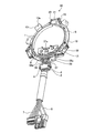
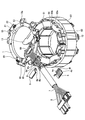
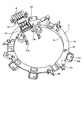
- FIG. 1 is a perspective view showing a configuration of a stator assembly of an electric motor according to Embodiment 1.
- FIG. FIG. 2 is a perspective view of the lead wire assembly in the first embodiment.
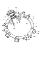
- FIG. 3 is a perspective view of a lead wire wiring component in which the lead wire lead-out component according to the first embodiment is assembled.
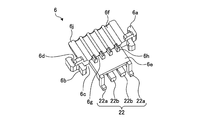
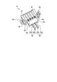
- FIG. 4 is a perspective view of the lead wire lead-out component in the first embodiment.
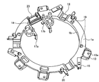
- FIG. 5 is a perspective view of the lead wire wiring component according to the first embodiment.
- FIG. 6 is an exploded view of the stator assembly of the electric motor in the first embodiment.
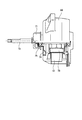
- FIG. 7 is a diagram illustrating an example of the configuration of the electric motor according to the first embodiment.
- the stator assembly 30 includes an annular stator 10 and a lead wire wiring component 1 that is assembled to the stator 10 at one end in the axial direction of the stator 10 and to which the sensor lead wire 7 and the power supply lead wire 8 are wired.
- the sensor substrate 11 (substrate) assembled to the lead wire wiring component 1 and connected to the sensor lead wire 7 via the board-in connector 80, and the lead wire lead-out component for extracting the sensor lead wire 7 and the power supply lead wire 8. 6 and the lead wire lead-out component 6 to hold the power lead wire 8 and the power supply lead wire holding component 4 and the lead wire lead-out component 6 to hold the sensor lead wire 7 and the sensor lead wire holding component. 5 (FIG. 1).
- the insulating part 83 is formed by molding a thermoplastic resin such as PBT (polybutylene terephthalate) integrally with the stator core 82 or by assembling the stator 10 after the molding. One end of the magnet wire is drawn around the hook portion 85 of the terminal 12 and joined to the hook portion 85 by fusing or soldering, and the other end of the end is combined with each other to form a neutral point.
- the stator 10 is configured by bending a belt-shaped core constituting the stator core 82 provided with the insulating portion 83, the coil 84, the terminal 12, and the like into an annular shape and welding the butted portions.
- connection side the side including the terminal 12 in the axial direction of the stator core 82 is referred to as a connection side, and the opposite side is referred to as an anti-connection side.
- anti-connection side the opposite side is referred to as an anti-connection side.
- the “axial direction” is the axial direction of the stator core 82.
- the insulating outer wall 83a constituting the insulating portion 83 prevents the coil 84 from falling to the outer peripheral side.
- a plurality of pins 81 for attaching the lead wire wiring component 1 to the stator 10 are provided on the connection side of the insulating outer wall 83a (FIG. 6).
- the insulating inner wall 83b that constitutes the insulating portion 83 prevents the coil 84 from falling to the inner peripheral side.
- a protrusion (not shown) is provided on the side opposite to the insulating inner wall 83b.
- a protrusion (not shown) provided on the side opposite to the connection side is in contact with the die core member when the stator 10 is placed on the die core member during molding, and serves as an axial stopper. used.
- the insulating outer wall 83a is formed so that its axial length is slightly longer than that of the coil 84, and the height of the insulating outer wall 83a on the anti-connection side is slightly higher than the height of the coil 84 on the anti-connection side. Further, the coil 84 is formed such that its axial length becomes shorter as it goes from the insulating outer wall 83a toward the insulating inner wall 83b, and its height on the anti-connection side becomes lower as it goes from the insulating outer wall 83a toward the insulating inner wall 83b.
- the lead wire wiring component 1 includes an annular plate portion 1a, an inner wall 1b, a mounting foot 13, a projection 14, a lead wire terminal holding portion 15, assembly feet 17a and 17b, a recess portion 18, a misalignment preventing projection 19, and a core wire holding portion. 20 (FIGS. 3 and 5).
- the annular plate portion 1a is formed in an annular shape by molding a thermoplastic resin such as PBT.
- a plurality of mounting legs 13 used when the lead wire wiring component 1 is assembled to the stator 10 are provided on the outer peripheral side of the annular plate portion 1a.
- the number of mounting feet 13 is, for example, four.
- a hole 13 a for inserting the terminal 12 is formed in the mounting foot 13.
- An inner wall 1b for routing the power supply lead 8 from the lead wire lead-out component 6 to the lead wire terminal holding portion 15 is provided on the inner peripheral side of the annular plate portion 1a.
- the inner wall 1b is provided with a positional deviation preventing projection 19 protruding outward in the radial direction (see FIG. 2).
- the misalignment prevention projection 19 positions the power supply lead 8 in the axial direction.
- the lead wire lead component 6 is assembled to the lead wire lead component 1 so that the lead wire lead component 1 and the lead wire lead component 6 can be handled as a single unit so that the sensor lead wire 7 and the power supply lead wire 8 can be wired. Can be easily. Further, when the stator 10 assembled with the sensor lead wire 7 and the power supply lead wire 8 is transported, even if a load is applied to the sensor lead wire 7 and the power supply lead wire 8, the lead wire lead-out component 6 becomes the lead wire wiring component 1. Therefore, no load is applied to the joint between the power supply lead wire 8 and the stator 10 or the joint between the sensor lead wire 7 and the sensor substrate 11, and the assembly workability is improved. Quality is improved.
- the protrusion 22 also has a function of guiding the sensor lead wire 7 and the power supply lead wire 8 drawn from the lead wire wiring component 1 to the lead wire lead-out component 6.
- the protrusion 22 may include a hook portion (not shown) that is engaged with the lead wire guide 23.
- a hook portion (not shown) is formed in an L shape so that the tip end portion of the projection portion 22b extends slightly toward the projection portion 22a in the axial direction, and the hook portion (not shown) is used as the lead wire guide 23. It can be hooked on the end of the shaft center side.
- the length of the protrusion 22a in the radial direction requires at least the width of the lead wire guide 23.
- a hook part (not shown) can also be provided in both protrusion part 22b or protrusion part 22a, 22b.
- the power lead wire holding component 4 is assembled to the lead wire lead-out component 6 by engaging the foot 4 b with the locking portion 6 b of the lead wire lead-out component 6. Attached. At this time, the power supply lead wire holding component 4 is positioned in the axial direction by the protrusion 4f. Further, when the power supply lead wire holding component 4 is engaged with the lead wire lead-out component 6, the rib 4 c provided on the power supply lead wire holding component 4 comes into contact with the lead wire lead-out component 6, whereby the power supply lead wire 8. However, the size of the opening exposed from the lead wire lead-out component 6 can be suppressed.
- the sensor substrate 11 is assembled to the lead wire wiring component 1 by the assembly legs 17 a and 17 b and the protrusions 14 of the lead wire wiring component 1.
- the board-in connector 80 is soldered to the sensor board 11.
- the sensor lead wire 7 is wired to the surface opposite to the surface where the power supply lead wire 8 is wired to the lead wire wiring component 1 (the side opposite to the stator of the lead wire wiring component 1), and is connected to the lead wire lead-out component 6. It is drawn around.
- the sensor lead wire 7 is lightly held by the holding protrusion 6 h of the lead wire lead-out component 6 and the foot 4 b of the power supply lead wire holding component 4.
- the sensor lead wire 7 is held by the sensor lead wire holding component 5, and the power supply lead wire 8 is It is held by the power supply lead wire holding component 4.
- the sensor lead wire 7 and the power supply lead wire 8 can be firmly assembled to the lead wire lead-out component 6 respectively, and the quality can be improved as the reliability is improved.
- the foot 4b of the power supply lead wire holding component 4 is also used to hold the sensor lead wire 7, the assembly becomes easy, the cost can be reduced, and the quality improves as the assembly becomes easy. Can be planned.
- the stator assembly 30 assembled with the sensor lead wire 7 and the power supply lead wire 8 as described above removes the lead wire lead-out component 6 from the lead wire wiring component 1 when it is installed in the mold during molding.
- a mold stator is obtained by molding with a mold resin which is a thermosetting resin such as BMC (bulk molding compound).
- the lead wire lead-out component 6 When the stator assembly 30 is molded, the lead wire lead-out component 6 is pushed radially outward from the center, so that the state where the lead wire lead-out component 6 is removed from the lead wire wiring component 1 after molding is maintained. Since the predetermined position can be maintained without touching 82, the contact between the sensor lead wires 7 or between the power supply lead wires 8 is not deteriorated more than the state wired to the lead wire wiring component 1. Since the intrusion of moisture transmitted through the interface between the wire lead-out component 6 and the mold resin can be suppressed as much as possible, the quality of the stator 10 can be improved.
- the protrusions (not shown) formed on the non-connection side of the insulating inner wall 83b are the stator core 82. It is no longer exposed to the inner diameter side, and the effect of suppressing water permeation can be further enhanced.
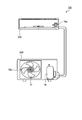
- FIG. 8 is a diagram showing an example of the configuration of an air conditioner incorporating the electric motor according to the present embodiment.
- the air conditioner 100 includes an indoor unit 200 and an outdoor unit 300 connected to the indoor unit 200.
- the indoor unit 200 includes an electric motor 70a as a drive source for the blower
- the outdoor unit 300 includes an electric motor 70b as a drive source for the blower.
- the electric motors 70a and 70b are, for example, the molded electric motors shown in FIG. 7, and use the stator 10 shown in FIG.
- a fan 77 rotated by an electric motor 70b and a compressor 78 are shown.
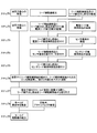
- FIG. 9 is a diagram showing an example of a method for manufacturing the electric motor according to the present embodiment.
- the method of manufacturing the motor includes a method of manufacturing the stator of the motor.
- the manufacturing process of the electric motor according to the present embodiment will be described.
- Step 1 The stator core 82 is manufactured.
- a lead wire wiring assembly (sensor lead wire 7, power supply lead wire 8, and board-in connector 80) is manufactured.
- the lead wire wiring component 1 and the lead wire lead-out component 6 are manufactured.
- Step 2 A coil 84 is provided by winding around the stator core 82.
- Step 3 The power supply lead wire holding component 4 is assembled to the lead wire lead-out component 6.
- the sensor substrate 11 is manufactured.
- Step 4 Assemble the sensor substrate 11 to the lead wire wiring component 1.
- the terminals of the board-in connector 80 are soldered to the sensor substrate 11.
- the sensor lead wire holding component 5 is manufactured.
- Step 5 Assemble the sensor lead wire holding component 5 to the lead wire lead-out component 6.
- the lead wire guide 23 for guiding the power supply lead wire 8 and the sensor lead wire 7 to the lead wire lead-out component 6 is provided in the lead wire wiring component 1, and the lead wire lead-out component 6 is provided. Is provided with a protrusion 22 that can be assembled to the lead wire guide 23 so that the lead wire lead-out component 6 can be attached to and detached from the lead wire wiring component 1.
- the protrusion 22 is composed of protrusions 22 a and 22 b that are spaced apart from each other in the axial direction by the thickness of the lead wire guide 23.
- the lead wire lead-out component 6 can be easily assembled to the lead wire wiring component 1 by fitting the lead wire guide 23 of the lead wire wiring component 1 between the protrusions 22a, 22b of the lead wire lead-out component 6.
- the quality improvement of an air conditioner can be aimed at by mounting the electric motor provided with the stator 10 in the air blower of an outdoor unit, for example.
- the electric motor according to the present embodiment can also be applied to electric devices other than air conditioners.
- the lead wire lead-out component 6 can have a structure that can be assembled to the lead wire guide 23.
- the lead wire lead-out component 6 has a protruding portion 22 that can be assembled to the lead wire guide 23, and the protruding portion 22 is removed from the lead wire guide 23 in the mold resin portion.
- the projecting portion 22 extends from the lead wire lead-out component 6 toward the radially inner side of the stator 10.
- the protrusion 22 is composed of protrusions 22a and 22b that are spaced apart from each other in the axial direction.
- the lead wire lead-out component 6 is formed by fitting the protrusions 22a and 22b to the lead wire guide 23.
- the lead wire wiring component 1 can be assembled.
- the protruding portion 22 may have a hook portion that is engaged with the lead wire guide 23.
- FIG. FIG. 10 is a perspective view of a lead wire wiring component assembled with the lead wire lead component in the present embodiment
- FIG. 11 is a perspective view of the lead wire lead component in the present embodiment
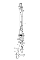
- 12 is a cross-sectional view of the lead wire wiring component with the lead wire lead-out component assembled in the present embodiment
- FIG. 13 shows the lead with the lead wire lead-out component separated in the present embodiment. It is sectional drawing of a line wiring component.
- FIGS. 1, 2, and 5 to 9 described in the first embodiment are also common to the present embodiment. Therefore, in the following, differences from the first embodiment will be mainly described, and description of matters common to the first embodiment will be omitted. 10 to 13, the same components as those in FIGS. 1 to 6 are denoted by the same reference numerals.
- the lead wire lead-out component 6 includes a plate-like base portion 6j, a pair of locking portions 6a (first locking portions) provided on both sides of the base portion 6j, and a pair of locking pins provided on both sides of the base portion 6j.
- a plurality of holding projections 6h that are provided above and constitute a sensor lead wire holding portion 6g for holding the sensor lead wire 7, and a plurality of projections protruding from the end of the plate-like portion 6e toward the lead wire wiring component 1 side Part 52 (FIG. 11).
- the lead wire lead-out component 6 can assemble the axial portion 52b of the protrusion 52 to the lead wire guide 23 by moving the lead wire lead-out component 6 in the axial direction (FIGS. 10, 12, and FIG. 13).
- the substantially L-shaped protrusion 52 is temporarily fixed by being assembled to the end portion on the axial center side of the lead wire guide 23.
- the lead wire lead-out component 6 can be easily detached from the lead wire wiring component 1 by pulling out the protrusion 52 assembled to the lead wire guide 23 in the axial direction (FIGS. 12 and 13).
- FIGS. 12 and 13 the lead wire guide 23 is not shown.
- the lead wire lead part 6 is assembled and temporarily fixed to the lead wire lead part 1 so that the lead wire lead part 1 and the lead wire lead part 6 can be handled as a unit, so that the sensor lead wire 7 and the power lead Wiring of the line 8 can be facilitated. Further, when the stator 10 assembled with the sensor lead wire 7 and the power supply lead wire 8 is transported, even if the sensor lead wire 7 and the power supply lead wire 8 are loaded, the lead wire lead-out component 6 is the lead wire wiring component. 1 so that no load is applied to the joint between the power supply lead wire 8 and the stator 10 or the joint between the sensor lead wire 7 and the sensor substrate 11, thereby improving the assembly workability. And quality is improved.
- the protrusion 52 also has a function of guiding the sensor lead wire 7 and the power supply lead wire 8 drawn from the lead wire wiring component 1 to the lead wire lead-out component 6.
- the lead wire lead-out component 6 is assembled to the lead wire wiring component 1 is not limited to the above example, and other structures can be used as long as the lead wire lead-out component 6 can be detachably assembled to the lead wire wiring component 1.
- the lead wire guide 23 is provided with an insertion hole into which the axial portion 52b of the protrusion 52 can be inserted, and the axial portion 52b of the protrusion 52 is inserted into the insertion hole. It is also possible to assemble to the wiring component 1.
- the protrusion part 52 should just have the axial direction part 52b at least.
- the sensor lead wire 7 and the power supply lead wire 8 are assembled when the stator 10 is molded in order to move the lead wire lead-out component 6 in the axial direction.
- the lead wire lead-out component 6 and the lead wire wiring component 1 can be separated. In other words, the lead wire lead-out component 6 is installed at a position moved a predetermined distance in the axial direction from a predetermined position of the stator 10 after molding in a state where the lead wire lead component 6 is assembled to the lead wire wiring component 1.
- the lead wire wiring component 1 assembled to the stator 10 is advanced by proceeding with the installation of the stator 10 on the mold, A predetermined gap is provided in the axial direction between the lead wire lead-out component 6.
- stator of the electric motor according to the present embodiment can be applied to the electric motor as shown in FIG. 7 as in the first embodiment. Further, the electric motor according to the present embodiment can be applied to an air conditioner as shown in FIG. 8 as in the first embodiment.
- the method for manufacturing the electric motor according to the present embodiment is the same as that of the first embodiment.
- the method of manufacturing the electric motor has been described by dividing it into (1) Step 1 to (9) Step 9, but in the present embodiment, (7) Step 7:
- the stator assembly 30 is installed in the mold, the lead wire lead-out component 6 is moved in the axial direction and removed from the lead wire wiring component 1.
- the other steps are the same as those in the first embodiment.
- the lead wire lead-out component 6 is removed from the lead wire lead-out component 1 so that the lead wire lead-out component 6 is formed in the mold resin portion after molding. Since the lead wire wiring component 1 is removed and the intrusion of moisture transmitted through the interface between the lead wire lead-out component 6 and the mold resin can be suppressed as much as possible, the quality of the stator 10 can be improved.
- the lead wire lead-out component 6 is pushed outward from the center by the molding pressure, so that the state where it is removed from the lead wire wiring component 1 is maintained even after molding. Thus, a predetermined position can be maintained without contacting the stator core 82.
- the lead wire lead-out component 6 is connected to the lead wire. Since it is assembled to the component 1 and temporarily fixed, no load is applied to the joint between the power supply lead 8 and the stator 10 or the joint between the sensor lead 7 and the sensor substrate 11. Workability is improved and quality is improved.
- the lead wire lead-out component 6 is removed from the lead wire wiring component 1, the lead wire lead-out component 6 is moved in the axial direction, so that the power supply lead wire 8 and the sensor lead wire 7 are connected when the stator 10 is molded. It is possible to separate the lead wire lead-out component 6 and the lead wire wiring component 1 during the process of installing the assembled stator 10 in the mold.
- the lead wire lead-out component 6 is removed from the lead wire wiring component 1, the lead wire lead-out component 6 is moved in the axial direction, so that it is easy to adjust the lead wire lead-out position of the electric motor after molding.
- a hook portion (not shown) for engaging with the lead wire guide 23 of the lead wire wiring component 1 can be provided on the protruding portion 52 of the lead wire lead-out component 6. Accordingly, the lead wire lead-out component 6 can be temporarily fixed to the lead wire wiring component 1 firmly.
- the quality improvement of an air conditioner can be aimed at by mounting the electric motor provided with the stator 10 in the air blower of an outdoor unit, for example.
- the electric motor according to the present embodiment can also be applied to electric devices other than air conditioners.
- the present invention is useful as an electric motor stator, an electric motor, an air conditioner, and a method of manufacturing an electric motor stator.
Landscapes
- Engineering & Computer Science (AREA)
- Power Engineering (AREA)
- Manufacturing & Machinery (AREA)
- Insulation, Fastening Of Motor, Generator Windings (AREA)
- Motor Or Generator Frames (AREA)
- Manufacture Of Motors, Generators (AREA)
Abstract
Description
図1は、本実施の形態に係る電動機の固定子組立の構成を示す斜視図、図2は、リード線組立の斜視図、図3は、リード線口出し部品を組付けたリード線配線部品の斜視図、図4は、リード線口出し部品の斜視図、図5は、リード線配線部品の斜視図、図6は、電動機の固定子組立の分解図である。以下、図1~図6を参照して、本実施の形態に係る電動機の固定子の構成について説明する。
(1)ステップ1:固定子鉄心82を製造する。併せて、リード線配線組立(センサリード線7、電源リード線8、及びボードインコネクタ80)を製造する。併せて、リード線配線部品1及びリード線口出し部品6を製造する。
(2)ステップ2:固定子鉄心82に巻線してコイル84を設ける。併せて、リード線配線部品1にリード線口出し部品6を組付けた後、リード線配線部品1に電源リード線8を配線する。このとき電源リード線8の芯線21が芯線保持部20まで引回される。併せて、電源リード線保持部品4を製造する。
(3)ステップ3:リード線口出し部品6に電源リード線保持部品4を組付ける。併せて、センサ基板11を製造する。
(4)ステップ4:リード線配線部品1にセンサ基板11を組付ける。センサ基板11には、ボードインコネクタ80の端子が半田付けされる。併せて、センサリード線保持部品5を製造する。
(5)ステップ5:リード線口出し部品6にセンサリード線保持部品5を組付ける。
(6)ステップ6:固定子10にリード線配線部品1を組付け、リード線配線部品1の取付け足13から出るピン81を熱溶着し、端子12と芯線21をスポット溶接する。
(7)ステップ7:固定子組立30をモールド金型に設置する際に、リード線口出し部品6をリード線配線部品1から取り外す。
(8)ステップ8:固定子組立30をモールド成形してモールド固定子を製造する。併せて、回転子、ブラケット等の部品を製造する。
(9)ステップ9:モールド固定子に回転子などを組付けて電動機を製造する。
図10は、本実施の形態におけるリード線口出し部品を組付けたリード線配線部品の斜視図、図11は、本実施の形態におけるリード線口出し部品の斜視図である。また、図12は、本実施の形態におけるリード線口出し部品を組付けた状態でのリード線配線部品の断面図、図13は、本実施の形態におけるリード線口出し部品を分離した状態でのリード線配線部品の断面図である。
(7)ステップ7:固定子組立30をモールド金型に設置する際に、リード線口出し部品6を軸方向に移動してリード線配線部品1から取り外す。
とすればよく、他のステップは実施の形態1と同じである。
Claims (12)
- 固定子と、
前記固定子の軸方向の一端に組付けられ、リード線が配線されるリード線配線部品と、
前記リード線を口出しするリード線口出し部品と、
前記固定子、前記リード線配線部品、及び前記リード線口出し部品を一体に覆うモールド樹脂部と、
を備え、
前記リード線配線部品は、前記リード線を前記リード線口出し部品にガイドするリード線ガイドを有し、
前記リード線口出し部品は、前記リード線ガイドに組付けることが可能であり、
前記リード線口出し部品は、前記モールド樹脂部内では、前記リード線ガイドから取り外された状態にあることを特徴とする電動機の固定子。 - 前記リード線口出し部品は、前記リード線ガイドに組み付けることが可能な構造を有することを特徴とする請求項1に記載の電動機の固定子。
- 前記リード線口出し部品は、前記リード線ガイドに組み付けることが可能な突起部を有し、
前記モールド樹脂部内では、前記突起部が前記リード線ガイドから取り外された状態にあることを特徴とする請求項1に記載の電動機の固定子。 - 前記突起部は、前記リード線口出し部品から前記固定子の径方向内側に向かって伸びていることを特徴とする請求項3に記載の電動機の固定子。
- 前記突起部は、前記軸方向に互いに離隔して配置された第1及び第2の突起部から成り、
前記リード線口出し部品は、前記第1及び第2の突起部が前記リード線ガイドに嵌め合されることにより、前記リード線配線部品に組付け可能であることを特徴とする請求項4に記載の電動機の固定子。 - 前記突起部は、前記リード線口出し部品から前記固定子の前記軸方向の他端に向かって伸びていることを特徴とする請求項3に記載の電動機の固定子。
- 前記突起部は、前記リード線口出し部品から前記固定子の径方向内側に伸びた後に前記軸方向に屈曲して前記固定子の前記軸方向の他端に向かって伸びていることを特徴とする請求項6に記載の電動機の固定子。
- 前記突起部は、前記リード線ガイドに係り止めされるフック部を有していることを特徴とする請求項3に記載の電動機の固定子。
- 前記リード線口出し部品は、固定子組立時には前記リード線ガイドに組み付けられ、モールド成形前に前記リード線ガイドから取り外されるものであることを特徴とする請求項1に記載の電動機の固定子。
- 請求項1から9のいずれか1項に記載の電動機の固定子を備えることを特徴とする電動機。
- 請求項10に記載の電動機を備えることを特徴とする空気調和機。
- リード線口出し部品をリード線配線部品のリード線ガイドに組付けるステップと、
前記リード線配線部品にリード線を配線するステップと、
前記リード線配線部品を固定子に組付けて固定子組立を製造するステップと、
前記固定子組立をモールド金型に設置する際に、前記リード線口出し部品を前記リード線ガイドから取り外すステップと、
前記固定子組立をモールド樹脂で一体に成形するステップと、
を含むことを特徴とする電動機の固定子の製造方法。
Priority Applications (5)
| Application Number | Priority Date | Filing Date | Title |
|---|---|---|---|
| JP2015506823A JP5951110B2 (ja) | 2013-03-21 | 2014-03-19 | 電動機の固定子、電動機、空気調和機、及び電動機の固定子の製造方法 |
| US14/772,138 US10044239B2 (en) | 2013-03-21 | 2014-03-19 | Stator of electric motor, electric motor, air conditioner, and method of manufacturing stator of electric motor |
| EP14770265.8A EP2978107B1 (en) | 2013-03-21 | 2014-03-19 | Stator of electric motor, electric motor, air conditioning unit, and method for manufacturing stator of electric motor |
| CN201480013676.2A CN105027394B (zh) | 2013-03-21 | 2014-03-19 | 电动机的模制定子、电动机、空调机以及电动机的模制定子的制造方法 |
| CN201420131252.3U CN203859600U (zh) | 2013-03-21 | 2014-03-21 | 电动机的定子、电动机以及空调机 |
Applications Claiming Priority (4)
| Application Number | Priority Date | Filing Date | Title |
|---|---|---|---|
| JPPCT/JP2013/058134 | 2013-03-21 | ||
| JPPCT/JP2013/058133 | 2013-03-21 | ||
| PCT/JP2013/058133 WO2014147797A1 (ja) | 2013-03-21 | 2013-03-21 | 電動機の固定子、電動機、空気調和機、及び電動機の固定子の製造方法 |
| JP2013058134 | 2013-03-21 |
Publications (1)
| Publication Number | Publication Date |
|---|---|
| WO2014148537A1 true WO2014148537A1 (ja) | 2014-09-25 |
Family
ID=51580211
Family Applications (1)
| Application Number | Title | Priority Date | Filing Date |
|---|---|---|---|
| PCT/JP2014/057497 Ceased WO2014148537A1 (ja) | 2013-03-21 | 2014-03-19 | 電動機の固定子、電動機、空気調和機、及び電動機の固定子の製造方法 |
Country Status (5)
| Country | Link |
|---|---|
| US (1) | US10044239B2 (ja) |
| EP (1) | EP2978107B1 (ja) |
| JP (1) | JP5951110B2 (ja) |
| CN (2) | CN105027394B (ja) |
| WO (1) | WO2014148537A1 (ja) |
Cited By (5)
| Publication number | Priority date | Publication date | Assignee | Title |
|---|---|---|---|---|
| WO2016006594A1 (ja) * | 2014-07-10 | 2016-01-14 | 三菱電機株式会社 | 電動機の固定子、電動機および空気調和機 |
| WO2016063427A1 (ja) * | 2014-10-24 | 2016-04-28 | 三菱電機株式会社 | 電動機の固定子、電動機および空気調和機 |
| WO2016063428A1 (ja) * | 2014-10-24 | 2016-04-28 | 三菱電機株式会社 | 電動機の固定子、電動機および空気調和機 |
| WO2020234990A1 (ja) * | 2019-05-21 | 2020-11-26 | 三菱電機株式会社 | 圧縮機及び空気調和機の室外機 |
| WO2023176339A1 (ja) * | 2022-03-17 | 2023-09-21 | 三菱電機株式会社 | 回転電機のステータ、回転電機、回転電機のステータの製造方法、および、回転電機の製造方法 |
Families Citing this family (12)
| Publication number | Priority date | Publication date | Assignee | Title |
|---|---|---|---|---|
| AU2013403563B2 (en) * | 2013-10-22 | 2017-04-20 | Mitsubishi Electric Corporation | Molded stator, molded electric motor, and air conditioner |
| JP6282347B2 (ja) * | 2014-07-11 | 2018-02-21 | 三菱電機株式会社 | 電動機の固定子、電動機、および空気調和機 |
| EP3174754B1 (en) * | 2014-08-01 | 2020-01-08 | PIAGGIO & C. S.p.A. | Permanent magnet electric motor and generator and hybrid motor comprising it in a scooter |
| KR102090830B1 (ko) * | 2016-08-04 | 2020-03-18 | 미쓰비시덴키 가부시키가이샤 | 전동기 및 공기 조화 장치 |
| US10439463B2 (en) * | 2017-06-27 | 2019-10-08 | Siemens Energy, Inc. | Assembly and method for supporting generator stator end winding coils |
| JP6710334B2 (ja) * | 2017-07-10 | 2020-06-17 | 三菱電機株式会社 | 電動機、空気調和機、及び電気掃除機、並びに電動機の製造方法 |
| JP2019180195A (ja) * | 2018-03-30 | 2019-10-17 | 日本電産サーボ株式会社 | モータ、遠心ファン |
| TWI674734B (zh) * | 2018-11-30 | 2019-10-11 | 建準電機工業股份有限公司 | 接線端子及具有該接線端子之馬達定子 |
| CN112688461B (zh) * | 2021-01-27 | 2025-05-23 | Abb瑞士股份有限公司 | 电机的定子以及电机 |
| DE102023201223A1 (de) * | 2023-02-14 | 2024-08-14 | Zf Friedrichshafen Ag | Verschaltungsanordnung mit einer Positioniereinrichtung, Verwendung der Positioniereinrichtung sowie Verfahren zur Montage der Verschaltungsanordnung |
| DE102023201220A1 (de) * | 2023-02-14 | 2024-08-14 | Zf Friedrichshafen Ag | Verschaltungsanordnung mit einer Positionierhilfe sowie Montagevorrichtung und Verfahren zur Montage der Verschaltungsanordnung |
| KR20240147284A (ko) * | 2023-03-31 | 2024-10-08 | 삼성전자주식회사 | 스테이터 및 이를 포함하는 모터 |
Citations (6)
| Publication number | Priority date | Publication date | Assignee | Title |
|---|---|---|---|---|
| JP2001178062A (ja) * | 1999-12-20 | 2001-06-29 | Mitsubishi Electric Corp | 電動機 |
| JP2004350346A (ja) | 2003-05-20 | 2004-12-09 | Matsushita Electric Ind Co Ltd | モールドモータの固定子および電動機ならびに駆動システム |
| JP2009112067A (ja) * | 2007-10-26 | 2009-05-21 | Nidec Shibaura Corp | モールドモータ |
| JP2010028909A (ja) * | 2008-07-16 | 2010-02-04 | Mitsubishi Electric Corp | モールド固定子及びポンプ及び給湯機及び電動機及びポンプの製造方法 |
| JP2010035365A (ja) * | 2008-07-30 | 2010-02-12 | Mitsubishi Electric Corp | 電動機の固定子及び電動機及び空気調和機及び電動機の製造方法 |
| JP2010273525A (ja) | 2009-05-25 | 2010-12-02 | Mitsubishi Electric Corp | 電動機の固定子及び電動機及び空気調和機及び電動機の製造方法 |
Family Cites Families (6)
| Publication number | Priority date | Publication date | Assignee | Title |
|---|---|---|---|---|
| US4451750A (en) * | 1981-02-03 | 1984-05-29 | Elektro-Mechanik Gmbh | Protective arrangement for a plug-connected electric motor sealed against pressure, vapors and radiation |
| JPH073810U (ja) | 1989-02-20 | 1995-01-20 | トーア・スチール株式会社 | 熱間圧延線材の蛇行搬送装置 |
| JP3602032B2 (ja) * | 2000-04-25 | 2004-12-15 | 三菱電機株式会社 | 電動機の固定子 |
| JP3875617B2 (ja) | 2002-10-11 | 2007-01-31 | 三菱電機株式会社 | 電動機の固定子及び電動機及びモールド電動機及び送風機及び空気調和機及び電動機の固定子の製造方法 |
| JP4398437B2 (ja) * | 2006-02-21 | 2010-01-13 | 三菱電機株式会社 | 電動機の固定子及び電動機及び空気調和機 |
| JP4785907B2 (ja) * | 2008-11-28 | 2011-10-05 | 三菱電機株式会社 | 電動機の固定子及び電動機及び空気調和機及び電動機の製造方法 |
-
2014
- 2014-03-19 US US14/772,138 patent/US10044239B2/en active Active
- 2014-03-19 CN CN201480013676.2A patent/CN105027394B/zh not_active Expired - Fee Related
- 2014-03-19 WO PCT/JP2014/057497 patent/WO2014148537A1/ja not_active Ceased
- 2014-03-19 JP JP2015506823A patent/JP5951110B2/ja not_active Expired - Fee Related
- 2014-03-19 EP EP14770265.8A patent/EP2978107B1/en not_active Not-in-force
- 2014-03-21 CN CN201420131252.3U patent/CN203859600U/zh not_active Expired - Lifetime
Patent Citations (6)
| Publication number | Priority date | Publication date | Assignee | Title |
|---|---|---|---|---|
| JP2001178062A (ja) * | 1999-12-20 | 2001-06-29 | Mitsubishi Electric Corp | 電動機 |
| JP2004350346A (ja) | 2003-05-20 | 2004-12-09 | Matsushita Electric Ind Co Ltd | モールドモータの固定子および電動機ならびに駆動システム |
| JP2009112067A (ja) * | 2007-10-26 | 2009-05-21 | Nidec Shibaura Corp | モールドモータ |
| JP2010028909A (ja) * | 2008-07-16 | 2010-02-04 | Mitsubishi Electric Corp | モールド固定子及びポンプ及び給湯機及び電動機及びポンプの製造方法 |
| JP2010035365A (ja) * | 2008-07-30 | 2010-02-12 | Mitsubishi Electric Corp | 電動機の固定子及び電動機及び空気調和機及び電動機の製造方法 |
| JP2010273525A (ja) | 2009-05-25 | 2010-12-02 | Mitsubishi Electric Corp | 電動機の固定子及び電動機及び空気調和機及び電動機の製造方法 |
Non-Patent Citations (1)
| Title |
|---|
| See also references of EP2978107A4 |
Cited By (12)
| Publication number | Priority date | Publication date | Assignee | Title |
|---|---|---|---|---|
| WO2016006594A1 (ja) * | 2014-07-10 | 2016-01-14 | 三菱電機株式会社 | 電動機の固定子、電動機および空気調和機 |
| US10008902B2 (en) | 2014-07-10 | 2018-06-26 | Mitsubishi Electric Corporation | Stator for electric motor, electric motor, and air conditioner |
| WO2016063427A1 (ja) * | 2014-10-24 | 2016-04-28 | 三菱電機株式会社 | 電動機の固定子、電動機および空気調和機 |
| WO2016063428A1 (ja) * | 2014-10-24 | 2016-04-28 | 三菱電機株式会社 | 電動機の固定子、電動機および空気調和機 |
| JPWO2016063428A1 (ja) * | 2014-10-24 | 2017-04-27 | 三菱電機株式会社 | 電動機の固定子、電動機および空気調和機 |
| CN107078590A (zh) * | 2014-10-24 | 2017-08-18 | 三菱电机株式会社 | 电动机的定子、电动机以及空调 |
| US10141811B2 (en) | 2014-10-24 | 2018-11-27 | Mitsubishi Electric Corporation | Stator for electric motor, electric motor, and air conditioner |
| CN107078590B (zh) * | 2014-10-24 | 2019-05-14 | 三菱电机株式会社 | 电动机的定子、电动机以及空调 |
| WO2020234990A1 (ja) * | 2019-05-21 | 2020-11-26 | 三菱電機株式会社 | 圧縮機及び空気調和機の室外機 |
| WO2023176339A1 (ja) * | 2022-03-17 | 2023-09-21 | 三菱電機株式会社 | 回転電機のステータ、回転電機、回転電機のステータの製造方法、および、回転電機の製造方法 |
| JPWO2023176339A1 (ja) * | 2022-03-17 | 2023-09-21 | ||
| JP7770753B2 (ja) | 2022-03-17 | 2025-11-17 | 三菱電機株式会社 | 回転電機のステータ、回転電機、回転電機のステータの製造方法、および、回転電機の製造方法 |
Also Published As
| Publication number | Publication date |
|---|---|
| CN105027394A (zh) | 2015-11-04 |
| JPWO2014148537A1 (ja) | 2017-02-16 |
| EP2978107B1 (en) | 2017-12-06 |
| JP5951110B2 (ja) | 2016-07-13 |
| EP2978107A1 (en) | 2016-01-27 |
| CN203859600U (zh) | 2014-10-01 |
| CN105027394B (zh) | 2018-02-09 |
| US10044239B2 (en) | 2018-08-07 |
| US20160036279A1 (en) | 2016-02-04 |
| EP2978107A4 (en) | 2016-11-02 |
Similar Documents
| Publication | Publication Date | Title |
|---|---|---|
| JP5951110B2 (ja) | 電動機の固定子、電動機、空気調和機、及び電動機の固定子の製造方法 | |
| JP6141440B2 (ja) | モールド固定子、モールド電動機および空気調和機 | |
| JP6184600B2 (ja) | 電動機の固定子、電動機および空気調和機 | |
| WO2014080675A1 (ja) | 電動機、空気調和機、および電動機の製造方法 | |
| CN203896077U (zh) | 模制定子、模制电动机和空调机 | |
| JPWO2016006112A1 (ja) | 電動機の固定子、電動機、および空気調和機 | |
| JP6017059B2 (ja) | モールド固定子、モールド電動機および空気調和機 | |
| WO2015162692A1 (ja) | 電動機の固定子、モールド電動機、および空気調和機 | |
| JP6087443B2 (ja) | 固定子、電動機及び空気調和機 | |
| JP6320555B2 (ja) | 電動機の固定子、電動機および空気調和機 | |
| CN203800712U (zh) | 模制定子、模制电动机和空调机 | |
| JP6320554B2 (ja) | 電動機の固定子、電動機および空気調和機 | |
| WO2014147797A1 (ja) | 電動機の固定子、電動機、空気調和機、及び電動機の固定子の製造方法 |
Legal Events
| Date | Code | Title | Description |
|---|---|---|---|
| WWE | Wipo information: entry into national phase |
Ref document number: 201480013676.2 Country of ref document: CN |
|
| 121 | Ep: the epo has been informed by wipo that ep was designated in this application |
Ref document number: 14770265 Country of ref document: EP Kind code of ref document: A1 |
|
| ENP | Entry into the national phase |
Ref document number: 2015506823 Country of ref document: JP Kind code of ref document: A |
|
| WWE | Wipo information: entry into national phase |
Ref document number: 14772138 Country of ref document: US |
|
| NENP | Non-entry into the national phase |
Ref country code: DE |
|
| WWE | Wipo information: entry into national phase |
Ref document number: 2014770265 Country of ref document: EP |