WO2014148545A1 - 内燃機関の排気浄化装置 - Google Patents
内燃機関の排気浄化装置 Download PDFInfo
- Publication number
- WO2014148545A1 WO2014148545A1 PCT/JP2014/057511 JP2014057511W WO2014148545A1 WO 2014148545 A1 WO2014148545 A1 WO 2014148545A1 JP 2014057511 W JP2014057511 W JP 2014057511W WO 2014148545 A1 WO2014148545 A1 WO 2014148545A1
- Authority
- WO
- WIPO (PCT)
- Prior art keywords
- temperature
- catalyst
- oxidation catalyst
- oxidation
- exhaust
- Prior art date
- Legal status (The legal status is an assumption and is not a legal conclusion. Google has not performed a legal analysis and makes no representation as to the accuracy of the status listed.)
- Ceased
Links
Images


Classifications
-
- F—MECHANICAL ENGINEERING; LIGHTING; HEATING; WEAPONS; BLASTING
- F01—MACHINES OR ENGINES IN GENERAL; ENGINE PLANTS IN GENERAL; STEAM ENGINES
- F01N—GAS-FLOW SILENCERS OR EXHAUST APPARATUS FOR MACHINES OR ENGINES IN GENERAL; GAS-FLOW SILENCERS OR EXHAUST APPARATUS FOR INTERNAL-COMBUSTION ENGINES
- F01N3/00—Exhaust or silencing apparatus having means for purifying, rendering innocuous, or otherwise treating exhaust
- F01N3/08—Exhaust or silencing apparatus having means for purifying, rendering innocuous, or otherwise treating exhaust for rendering innocuous
- F01N3/10—Exhaust or silencing apparatus having means for purifying, rendering innocuous, or otherwise treating exhaust for rendering innocuous by thermal or catalytic conversion of noxious components of exhaust
- F01N3/24—Exhaust or silencing apparatus having means for purifying, rendering innocuous, or otherwise treating exhaust for rendering innocuous by thermal or catalytic conversion of noxious components of exhaust characterised by constructional aspects of converting apparatus
- F01N3/36—Arrangements for supply of additional fuel
-
- F—MECHANICAL ENGINEERING; LIGHTING; HEATING; WEAPONS; BLASTING
- F01—MACHINES OR ENGINES IN GENERAL; ENGINE PLANTS IN GENERAL; STEAM ENGINES
- F01N—GAS-FLOW SILENCERS OR EXHAUST APPARATUS FOR MACHINES OR ENGINES IN GENERAL; GAS-FLOW SILENCERS OR EXHAUST APPARATUS FOR INTERNAL-COMBUSTION ENGINES
- F01N11/00—Monitoring or diagnostic devices for exhaust-gas treatment apparatus
- F01N11/002—Monitoring or diagnostic devices for exhaust-gas treatment apparatus the diagnostic devices measuring or estimating temperature or pressure in, or downstream of the exhaust apparatus
-
- F—MECHANICAL ENGINEERING; LIGHTING; HEATING; WEAPONS; BLASTING
- F01—MACHINES OR ENGINES IN GENERAL; ENGINE PLANTS IN GENERAL; STEAM ENGINES
- F01N—GAS-FLOW SILENCERS OR EXHAUST APPARATUS FOR MACHINES OR ENGINES IN GENERAL; GAS-FLOW SILENCERS OR EXHAUST APPARATUS FOR INTERNAL-COMBUSTION ENGINES
- F01N13/00—Exhaust or silencing apparatus characterised by constructional features
- F01N13/009—Exhaust or silencing apparatus characterised by constructional features having two or more separate purifying devices arranged in series
-
- F—MECHANICAL ENGINEERING; LIGHTING; HEATING; WEAPONS; BLASTING
- F01—MACHINES OR ENGINES IN GENERAL; ENGINE PLANTS IN GENERAL; STEAM ENGINES
- F01N—GAS-FLOW SILENCERS OR EXHAUST APPARATUS FOR MACHINES OR ENGINES IN GENERAL; GAS-FLOW SILENCERS OR EXHAUST APPARATUS FOR INTERNAL-COMBUSTION ENGINES
- F01N3/00—Exhaust or silencing apparatus having means for purifying, rendering innocuous, or otherwise treating exhaust
- F01N3/08—Exhaust or silencing apparatus having means for purifying, rendering innocuous, or otherwise treating exhaust for rendering innocuous
- F01N3/10—Exhaust or silencing apparatus having means for purifying, rendering innocuous, or otherwise treating exhaust for rendering innocuous by thermal or catalytic conversion of noxious components of exhaust
- F01N3/103—Oxidation catalysts for HC and CO only
-
- F—MECHANICAL ENGINEERING; LIGHTING; HEATING; WEAPONS; BLASTING
- F01—MACHINES OR ENGINES IN GENERAL; ENGINE PLANTS IN GENERAL; STEAM ENGINES
- F01N—GAS-FLOW SILENCERS OR EXHAUST APPARATUS FOR MACHINES OR ENGINES IN GENERAL; GAS-FLOW SILENCERS OR EXHAUST APPARATUS FOR INTERNAL-COMBUSTION ENGINES
- F01N3/00—Exhaust or silencing apparatus having means for purifying, rendering innocuous, or otherwise treating exhaust
- F01N3/08—Exhaust or silencing apparatus having means for purifying, rendering innocuous, or otherwise treating exhaust for rendering innocuous
- F01N3/10—Exhaust or silencing apparatus having means for purifying, rendering innocuous, or otherwise treating exhaust for rendering innocuous by thermal or catalytic conversion of noxious components of exhaust
- F01N3/105—General auxiliary catalysts, e.g. upstream or downstream of the main catalyst
- F01N3/106—Auxiliary oxidation catalysts
-
- F—MECHANICAL ENGINEERING; LIGHTING; HEATING; WEAPONS; BLASTING
- F01—MACHINES OR ENGINES IN GENERAL; ENGINE PLANTS IN GENERAL; STEAM ENGINES
- F01N—GAS-FLOW SILENCERS OR EXHAUST APPARATUS FOR MACHINES OR ENGINES IN GENERAL; GAS-FLOW SILENCERS OR EXHAUST APPARATUS FOR INTERNAL-COMBUSTION ENGINES
- F01N3/00—Exhaust or silencing apparatus having means for purifying, rendering innocuous, or otherwise treating exhaust
- F01N3/08—Exhaust or silencing apparatus having means for purifying, rendering innocuous, or otherwise treating exhaust for rendering innocuous
- F01N3/10—Exhaust or silencing apparatus having means for purifying, rendering innocuous, or otherwise treating exhaust for rendering innocuous by thermal or catalytic conversion of noxious components of exhaust
- F01N3/18—Exhaust or silencing apparatus having means for purifying, rendering innocuous, or otherwise treating exhaust for rendering innocuous by thermal or catalytic conversion of noxious components of exhaust characterised by methods of operation; Control
- F01N3/20—Exhaust or silencing apparatus having means for purifying, rendering innocuous, or otherwise treating exhaust for rendering innocuous by thermal or catalytic conversion of noxious components of exhaust characterised by methods of operation; Control specially adapted for catalytic conversion
- F01N3/2006—Periodically heating or cooling catalytic reactors, e.g. at cold starting or overheating
- F01N3/2033—Periodically heating or cooling catalytic reactors, e.g. at cold starting or overheating using a fuel burner or introducing fuel into exhaust duct
-
- F—MECHANICAL ENGINEERING; LIGHTING; HEATING; WEAPONS; BLASTING
- F01—MACHINES OR ENGINES IN GENERAL; ENGINE PLANTS IN GENERAL; STEAM ENGINES
- F01N—GAS-FLOW SILENCERS OR EXHAUST APPARATUS FOR MACHINES OR ENGINES IN GENERAL; GAS-FLOW SILENCERS OR EXHAUST APPARATUS FOR INTERNAL-COMBUSTION ENGINES
- F01N3/00—Exhaust or silencing apparatus having means for purifying, rendering innocuous, or otherwise treating exhaust
- F01N3/08—Exhaust or silencing apparatus having means for purifying, rendering innocuous, or otherwise treating exhaust for rendering innocuous
- F01N3/10—Exhaust or silencing apparatus having means for purifying, rendering innocuous, or otherwise treating exhaust for rendering innocuous by thermal or catalytic conversion of noxious components of exhaust
- F01N3/18—Exhaust or silencing apparatus having means for purifying, rendering innocuous, or otherwise treating exhaust for rendering innocuous by thermal or catalytic conversion of noxious components of exhaust characterised by methods of operation; Control
- F01N3/20—Exhaust or silencing apparatus having means for purifying, rendering innocuous, or otherwise treating exhaust for rendering innocuous by thermal or catalytic conversion of noxious components of exhaust characterised by methods of operation; Control specially adapted for catalytic conversion
- F01N3/206—Adding periodically or continuously substances to exhaust gases for promoting purification, e.g. catalytic material in liquid form, NOx reducing agents
- F01N3/2066—Selective catalytic reduction [SCR]
-
- F—MECHANICAL ENGINEERING; LIGHTING; HEATING; WEAPONS; BLASTING
- F01—MACHINES OR ENGINES IN GENERAL; ENGINE PLANTS IN GENERAL; STEAM ENGINES
- F01N—GAS-FLOW SILENCERS OR EXHAUST APPARATUS FOR MACHINES OR ENGINES IN GENERAL; GAS-FLOW SILENCERS OR EXHAUST APPARATUS FOR INTERNAL-COMBUSTION ENGINES
- F01N3/00—Exhaust or silencing apparatus having means for purifying, rendering innocuous, or otherwise treating exhaust
- F01N3/08—Exhaust or silencing apparatus having means for purifying, rendering innocuous, or otherwise treating exhaust for rendering innocuous
- F01N3/10—Exhaust or silencing apparatus having means for purifying, rendering innocuous, or otherwise treating exhaust for rendering innocuous by thermal or catalytic conversion of noxious components of exhaust
- F01N3/18—Exhaust or silencing apparatus having means for purifying, rendering innocuous, or otherwise treating exhaust for rendering innocuous by thermal or catalytic conversion of noxious components of exhaust characterised by methods of operation; Control
- F01N3/20—Exhaust or silencing apparatus having means for purifying, rendering innocuous, or otherwise treating exhaust for rendering innocuous by thermal or catalytic conversion of noxious components of exhaust characterised by methods of operation; Control specially adapted for catalytic conversion
- F01N3/206—Adding periodically or continuously substances to exhaust gases for promoting purification, e.g. catalytic material in liquid form, NOx reducing agents
- F01N3/208—Control of selective catalytic reduction [SCR], e.g. by adjusting the dosing of reducing agent
-
- F—MECHANICAL ENGINEERING; LIGHTING; HEATING; WEAPONS; BLASTING
- F01—MACHINES OR ENGINES IN GENERAL; ENGINE PLANTS IN GENERAL; STEAM ENGINES
- F01N—GAS-FLOW SILENCERS OR EXHAUST APPARATUS FOR MACHINES OR ENGINES IN GENERAL; GAS-FLOW SILENCERS OR EXHAUST APPARATUS FOR INTERNAL-COMBUSTION ENGINES
- F01N9/00—Electrical control of exhaust gas treating apparatus
-
- F—MECHANICAL ENGINEERING; LIGHTING; HEATING; WEAPONS; BLASTING
- F01—MACHINES OR ENGINES IN GENERAL; ENGINE PLANTS IN GENERAL; STEAM ENGINES
- F01N—GAS-FLOW SILENCERS OR EXHAUST APPARATUS FOR MACHINES OR ENGINES IN GENERAL; GAS-FLOW SILENCERS OR EXHAUST APPARATUS FOR INTERNAL-COMBUSTION ENGINES
- F01N2550/00—Monitoring or diagnosing the deterioration of exhaust systems
- F01N2550/02—Catalytic activity of catalytic converters
-
- F—MECHANICAL ENGINEERING; LIGHTING; HEATING; WEAPONS; BLASTING
- F01—MACHINES OR ENGINES IN GENERAL; ENGINE PLANTS IN GENERAL; STEAM ENGINES
- F01N—GAS-FLOW SILENCERS OR EXHAUST APPARATUS FOR MACHINES OR ENGINES IN GENERAL; GAS-FLOW SILENCERS OR EXHAUST APPARATUS FOR INTERNAL-COMBUSTION ENGINES
- F01N2610/00—Adding substances to exhaust gases
- F01N2610/02—Adding substances to exhaust gases the substance being ammonia or urea
-
- F—MECHANICAL ENGINEERING; LIGHTING; HEATING; WEAPONS; BLASTING
- F01—MACHINES OR ENGINES IN GENERAL; ENGINE PLANTS IN GENERAL; STEAM ENGINES
- F01N—GAS-FLOW SILENCERS OR EXHAUST APPARATUS FOR MACHINES OR ENGINES IN GENERAL; GAS-FLOW SILENCERS OR EXHAUST APPARATUS FOR INTERNAL-COMBUSTION ENGINES
- F01N2610/00—Adding substances to exhaust gases
- F01N2610/03—Adding substances to exhaust gases the substance being hydrocarbons, e.g. engine fuel
-
- F—MECHANICAL ENGINEERING; LIGHTING; HEATING; WEAPONS; BLASTING
- F01—MACHINES OR ENGINES IN GENERAL; ENGINE PLANTS IN GENERAL; STEAM ENGINES
- F01N—GAS-FLOW SILENCERS OR EXHAUST APPARATUS FOR MACHINES OR ENGINES IN GENERAL; GAS-FLOW SILENCERS OR EXHAUST APPARATUS FOR INTERNAL-COMBUSTION ENGINES
- F01N2900/00—Details of electrical control or of the monitoring of the exhaust gas treating apparatus
- F01N2900/06—Parameters used for exhaust control or diagnosing
- F01N2900/16—Parameters used for exhaust control or diagnosing said parameters being related to the exhaust apparatus, e.g. particulate filter or catalyst
- F01N2900/1602—Temperature of exhaust gas apparatus
-
- F—MECHANICAL ENGINEERING; LIGHTING; HEATING; WEAPONS; BLASTING
- F01—MACHINES OR ENGINES IN GENERAL; ENGINE PLANTS IN GENERAL; STEAM ENGINES
- F01N—GAS-FLOW SILENCERS OR EXHAUST APPARATUS FOR MACHINES OR ENGINES IN GENERAL; GAS-FLOW SILENCERS OR EXHAUST APPARATUS FOR INTERNAL-COMBUSTION ENGINES
- F01N2900/00—Details of electrical control or of the monitoring of the exhaust gas treating apparatus
- F01N2900/06—Parameters used for exhaust control or diagnosing
- F01N2900/16—Parameters used for exhaust control or diagnosing said parameters being related to the exhaust apparatus, e.g. particulate filter or catalyst
- F01N2900/1626—Catalyst activation temperature
-
- Y—GENERAL TAGGING OF NEW TECHNOLOGICAL DEVELOPMENTS; GENERAL TAGGING OF CROSS-SECTIONAL TECHNOLOGIES SPANNING OVER SEVERAL SECTIONS OF THE IPC; TECHNICAL SUBJECTS COVERED BY FORMER USPC CROSS-REFERENCE ART COLLECTIONS [XRACs] AND DIGESTS
- Y02—TECHNOLOGIES OR APPLICATIONS FOR MITIGATION OR ADAPTATION AGAINST CLIMATE CHANGE
- Y02T—CLIMATE CHANGE MITIGATION TECHNOLOGIES RELATED TO TRANSPORTATION
- Y02T10/00—Road transport of goods or passengers
- Y02T10/10—Internal combustion engine [ICE] based vehicles
- Y02T10/12—Improving ICE efficiencies
-
- Y—GENERAL TAGGING OF NEW TECHNOLOGICAL DEVELOPMENTS; GENERAL TAGGING OF CROSS-SECTIONAL TECHNOLOGIES SPANNING OVER SEVERAL SECTIONS OF THE IPC; TECHNICAL SUBJECTS COVERED BY FORMER USPC CROSS-REFERENCE ART COLLECTIONS [XRACs] AND DIGESTS
- Y02—TECHNOLOGIES OR APPLICATIONS FOR MITIGATION OR ADAPTATION AGAINST CLIMATE CHANGE
- Y02T—CLIMATE CHANGE MITIGATION TECHNOLOGIES RELATED TO TRANSPORTATION
- Y02T10/00—Road transport of goods or passengers
- Y02T10/10—Internal combustion engine [ICE] based vehicles
- Y02T10/40—Engine management systems
Definitions
- the present invention relates to an exhaust gas purification apparatus for an internal combustion engine in which an oxidation catalyst and a selective reduction catalyst are provided in an exhaust passage.
- an oxidation catalyst having oxidation ability is provided in an exhaust passage of an internal combustion engine, and a selective reduction catalyst (SCR catalyst) that selectively reduces nitrogen oxide (NOx) in exhaust gas downstream of the oxidation catalyst.
- SCR catalyst selective reduction catalyst
- An exhaust emission control device is known.
- the oxidation catalyst can purify unburned fuel and oxygen monoxide discharged from the internal combustion engine, or oxidize the fuel supplied from the supply device to raise the exhaust temperature.
- the oxidation catalyst can selectively reduce NOx contained in the exhaust gas to some extent by using the fuel in the exhaust gas as a reducing agent.
- the NOx purification ability of an oxidation catalyst or an SCR catalyst actually depends on the catalyst temperature (bed temperature). Since the change in the exhaust temperature does not always coincide with the change in the bed temperature of the catalyst, the technique described in Patent Document 1 uses the fuel supply to the oxidation catalyst and the urea water supply to the SCR catalyst based on the exhaust temperature. It is difficult to appropriately supply the reducing agent according to the bed temperature of each catalyst. As a result, there is a possibility that the NOx purification ability may not be effectively exhibited in each catalyst.
- the present invention has been made in view of such circumstances, and in an exhaust purification device for an internal combustion engine in which an exhaust catalyst and an SCR catalyst are provided in an exhaust passage, the NOx purification rate of the entire exhaust purification device is increased. With the goal.
- an exhaust gas purification apparatus for an internal combustion engine includes: An oxidation catalyst that is provided in an exhaust passage of an internal combustion engine and has an oxidizing ability, and further, when the catalyst temperature belongs to a predetermined temperature range equal to or higher than its activation temperature, fuel supplied through the exhaust is used as a reducing agent.
- An oxidation catalyst that reduces NOx in the exhaust by using, A fuel supply section for supplying fuel to the oxidation catalyst via exhaust flowing into the oxidation catalyst; A selective reduction catalyst that is provided downstream of the oxidation catalyst in the exhaust passage and reduces NOx in the exhaust by using ammonia as a reducing agent; A reducing agent supply unit for supplying ammonia or an ammonia precursor to the selective catalytic reduction catalyst via exhaust flowing into the selective catalytic reduction catalyst; A control unit for controlling a fuel supply amount by the fuel supply unit; An exhaust purification device for an internal combustion engine comprising: The controller is In the case where the temperature of the oxidation catalyst belongs to the predetermined temperature range, when the selective catalytic reduction catalyst becomes inactive, the amount of fuel supplied by the fuel supply unit is reduced so that NOx is reduced by the oxidation catalyst.
- a first control for controlling In the case where the temperature of the oxidation catalyst exceeds the predetermined temperature range, when the selective catalytic reduction catalyst becomes inactive, the oxidation of the fuel by the oxidation catalyst does not affect the NOx purification rate by the selective catalytic reduction catalyst.
- the oxidation catalyst can oxidize the fuel and carbon monoxide in the exhaust by exhibiting sufficient oxidation ability when the catalyst temperature is equal to or higher than a predetermined activation temperature.
- the oxidation catalyst can further reduce NOx in the exhaust to some extent by using the fuel supplied via the exhaust as a reducing agent.
- the selective catalytic reduction catalyst reduces NOx in the exhaust by using ammonia as a reducing agent.
- NOx purification by reduction is mainly performed by an SCR catalyst.
- the SCR catalyst When the catalyst temperature becomes equal to or higher than a predetermined threshold temperature on the high temperature side, the SCR catalyst enters an active state with a high NOx purification rate.
- the SCR catalyst enters an inactive state with a low NOx purification rate when the catalyst temperature falls below a predetermined threshold temperature on the low temperature side.
- the control unit of the present invention performs the reduction of NOx by the oxidation catalyst when the SCR catalyst becomes inactive.
- First control for controlling the amount of fuel supplied by the fuel supply unit is executed.
- the control unit controls the fuel of the oxidation catalyst regardless of the NOx purification rate by the SCR catalyst.
- a second control for controlling the amount of fuel supplied by the fuel supply unit is executed so as to raise the temperature of the exhaust gas flowing into the selective catalytic reduction catalyst.
- the fuel is supplied so as to raise the temperature of the exhaust gas flowing into the selective catalytic reduction catalyst by oxidation of the fuel by the oxidation catalyst, thereby specializing in raising the temperature of the SCR catalyst.
- the supplied fuel can be supplied.
- the SCR catalyst can be shifted to the activated state more quickly, so that the NOx purification rate of the SCR catalyst having a high NOx purification ability can be increased at an early stage to ensure the NOx purification ability of the exhaust purification device as much as possible. can do.
- the catalyst when the temperature of the oxidation catalyst is equal to or higher than the activation temperature, when the SCR catalyst is in an inactive state, the catalyst that exhibits more NOx purification ability depending on the temperature of the oxidation catalyst.
- the amount of fuel supplied by the fuel supply unit is controlled so that the NOx purification rate increases. Therefore, the NOx purification rate of the entire exhaust gas purification device can be increased.
- the SCR catalyst When the catalyst temperature is within the temperature range determined by the above-mentioned predetermined threshold temperature on the high temperature side and the predetermined threshold temperature on the low temperature side, the SCR catalyst enters a transient state between the active state and the inactive state. Become. When the SCR catalyst is in a transient state, there is a correlation between the NOx purification rate of the SCR catalyst and the catalyst temperature, and the NOx purification rate of the SCR catalyst increases as the catalyst temperature increases. However, the NOx purification rate at this time is less than that in the active state.
- the SCR catalyst when the SCR catalyst is in a transient state, it is between the NOx purification rate and the ratio of nitrogen monoxide (NO) and nitrogen dioxide (NO 2 ) in the exhaust gas flowing into the SCR catalyst (NO 2 ratio).
- NO 2 ratio the ratio of nitrogen monoxide (NO) and nitrogen dioxide (NO 2 ) in the exhaust gas flowing into the SCR catalyst
- NOx ratio the ratio of nitrogen monoxide (NO) and nitrogen dioxide (NO 2 ) in the exhaust gas flowing into the SCR catalyst.
- the control unit of the present invention sets the NO 2 ratio in the exhaust gas flowing into the SCR catalyst to the SCR in the transient state.
- the fuel supply amount by the fuel supply unit is controlled so that the exhaust gas flowing into the SCR catalyst is raised by the oxidation of the fuel by the oxidation catalyst while the NOx purification rate of the catalyst is set to the predetermined ratio described above.
- the third control may be executed.
- control unit of the present invention provides a NOx purification rate of the oxidation catalyst when the first control is executed when the SCR catalyst is in a transient state when the temperature of the oxidation catalyst is equal to or higher than the activation temperature. If the NOx purification rate of the selective catalytic reduction catalyst when the third control is executed is predicted to be higher, the first control may be executed instead of the third control. As a result, it is possible to selectively execute control that is predicted to further increase the NOx purification rate of the oxidation catalyst, so that the NOx purification rate of the entire exhaust purification device can be reliably increased.
- the control unit of the present invention performs the third control when the SCR catalyst is in a transient state, and the temperature of the SCR catalyst is higher than the activation temperature.
- the third control may be executed also when it is predicted that the temperature of the SCR catalyst is lowered due to the temperature of the oxidation catalyst and the transition to the transient state is expected.
- the low-temperature exhaust gas flowing out from the oxidation catalyst may flow into the SCR catalyst arranged on the downstream side and reduce the temperature of the SCR catalyst. There is.
- the NOx purification rate of the SCR catalyst may decrease due to the temperature of the SCR catalyst decreasing to a temperature at which it becomes a transient state.
- the third control since the third control is executed in advance, it is possible to prevent the NOx purification rate of the SCR catalyst from decreasing after the transition to the transient state.
- control unit of the present invention is a case where the SCR catalyst is in a transient state when the temperature of the oxidation catalyst is equal to or higher than the activation temperature, and the temperature of the SCR catalyst is increased by the temperature of the oxidation catalyst to be in the active state.
- the third control may be prohibited.
- the temperature of the oxidation catalyst is sufficiently higher than the temperature of the SCR catalyst, it is predicted that the temperature of the SCR catalyst rises as high-temperature exhaust gas flowing out from the oxidation catalyst flows into the SCR catalyst. That is, even if the temperature of the SCR catalyst is not increased, the temperature of the SCR catalyst is expected to rise and shift to the active state.
- the third control since the third control is prohibited in such a case, the fuel supply amount can be reduced.
- the NOx purification of a catalyst that exhibits more NOx purification performance according to the temperature of the oxidation catalyst and the SCR catalyst. Since the fuel supply amount by the fuel supply unit is controlled so that the rate increases, the NOx purification rate of the entire exhaust gas purification device can be increased.
- FIG. 1 is a diagram showing a schematic configuration of an internal combustion engine to which the present invention is applied and its intake / exhaust system.
- An internal combustion engine 1 shown in FIG. 1 is a compression ignition type internal combustion engine (diesel engine) for an automobile having a plurality of cylinders.
- the internal combustion engine to which the present invention is applied is not limited to a compression ignition type internal combustion engine, but may be a spark ignition type internal combustion engine (gasoline engine).
- the internal combustion engine 1 includes a fuel injection valve 2 that injects fuel into the cylinder.
- the internal combustion engine 1 is connected to an exhaust passage 3 for circulating the exhaust discharged from the cylinder of the internal combustion engine 1.
- the fuel addition valve 4 In the exhaust passage 3, in order from the upstream side, the fuel addition valve 4, the oxidation catalyst 5, the first exhaust temperature sensor 6, the DPF 7, the urea water addition valve 8, the first NOx sensor 9, and the selective reduction catalyst 10 (hereinafter “SCR”).
- a second NOx sensor 11 and a second exhaust temperature sensor 12 are arranged.
- the fuel addition valve 4 as a fuel supply unit injects fuel into the exhaust gas flowing through the exhaust passage 3 and supplies the fuel to the oxidation catalyst 5.
- the fuel injection valve 2 may supply the fuel to the oxidation catalyst 5 by performing after injection or post injection for injecting fuel after combustion occurs in the cylinder. In this case, the fuel injection valve 2 corresponds to the fuel supply unit in this embodiment.
- the oxidation catalyst 5 oxidizes unburned fuel, carbon monoxide (CO), and the like discharged from the internal combustion engine 1 and suppresses them from being discharged to the atmosphere.
- the oxidation catalyst 5 oxidizes the fuel supplied by the fuel injection valve 2 and the fuel addition valve 4 to raise the exhaust temperature.
- the exhaust temperature is increased, for example, when the regeneration process of the DPF 7 is executed.
- the oxidation catalyst 5 can also purify NOx discharged from the internal combustion engine 1 by selective reduction using the fuel as a reducing agent when the catalyst temperature belongs to a predetermined temperature range equal to or higher than the activation temperature (details are given) Later).
- the SCR catalyst 10 purifies NOx by selectively reducing NOx in the exhaust gas to nitrogen (N 2 ) using ammonia.
- NOx purification is mainly performed by the SCR catalyst 10. That is, the NOx purification ability of the SCR catalyst 10 in the active state is higher than the purification ability exhibited by the oxidation catalyst 5.
- the SCR catalyst 10 accommodates a catalyst carrier having a function of adsorbing inflowed ammonia in a cylindrical casing. This catalyst carrier is obtained by coating a base material having a honeycomb-shaped cross section made of cordierite or Fe—Cr—Al heat-resistant steel with an alumina-based or zeolite-based active component (support).
- the DPF 7 and the SCR catalyst 10 are provided separately, but an SCR catalyst in which both are integrated may be used.
- a urea water addition valve for adding urea water in which urea ((NH 2 ) 2 CO) as an ammonia precursor is dissolved in the exhaust gas flowing in the exhaust passage 3 to the exhaust passage 3 upstream of the SCR catalyst 10. 8 is arranged.
- the urea water addition valve 8 is connected to a urea water tank 81 via a pump 80, and injects urea water pumped from the urea water tank 81 by the pump 80 into the exhaust passage 3.
- the injected urea water generates ammonia by a hydrolysis reaction due to the heat of the exhaust.
- the ammonia thus generated is consumed as a reducing agent in the SCR catalyst 10.
- ammonia water in which ammonia is dissolved may be added instead of urea water.
- the internal combustion engine 1 configured as described above is provided with an ECU 20 that is an electronic control unit for controlling the internal combustion engine 1.
- the ECU 20 is electrically connected to various devices such as the fuel injection valve 2, the fuel addition valve 4, the urea water addition valve 8, and the pump 80, and electrically controls them.
- the ECU 20 is electrically connected to various sensors such as the first exhaust temperature sensor 6, the first NOx sensor 9, the second NOx sensor 11, the second exhaust temperature sensor 12, the air flow meter 13, and the tachometer 14.
- the first exhaust temperature sensor 6 is disposed downstream of the oxidation catalyst 5 in the exhaust passage 3 and outputs an electrical signal correlated with the temperature of the exhaust gas flowing out from the oxidation catalyst 5.
- the ECU 20 estimates the catalyst temperature (bed temperature) of the oxidation catalyst 5 using the electrical signal output from the first exhaust temperature sensor 6.
- the second exhaust temperature sensor 12 is disposed downstream of the SCR catalyst 10 in the exhaust passage 3 and outputs an electrical signal correlated with the temperature of the exhaust gas flowing out from the SCR catalyst 10.
- the ECU 20 estimates the bed temperature of the SCR catalyst 10 using the electrical signal output from the second exhaust temperature sensor 12.
- the first NOx sensor 9 is arranged on the upstream side of the SCR catalyst 10 in the exhaust passage 3 and outputs an electric signal correlated with the NOx concentration in the exhaust flowing into the SCR catalyst 10.
- the second NOx sensor 11 is disposed downstream of the SCR catalyst 10 in the exhaust passage 3 and outputs an electrical signal correlated with the NOx concentration in the exhaust gas flowing out from the SCR catalyst 10.
- the ECU 20 estimates the NOx purification rate of the SCR catalyst 10 using the electrical signals output from these two NOx sensors.
- the air flow meter 13 is disposed in the intake passage of the internal combustion engine 1 and outputs an electrical signal correlated with the intake air amount sucked into the internal combustion engine 1.
- the ECU 20 calculates the amount of oxygen drawn into the cylinder of the internal combustion engine 1 using the electrical signal output from the air flow meter 13. Further, the ECU 20 uses the calculated amount of oxygen, the amount of fuel injected by the fuel injection valve 2, the engine speed of the internal combustion engine 1 detected by the tachometer 14, etc., to emit NOx from the internal combustion engine 1. The amount, that is, the amount of NOx flowing into the oxidation catalyst 5 is estimated.
- the catalytic function of the oxidation catalyst 5 will be described.
- a predetermined temperature Td1 for example, 150 ° C.
- the oxidation catalyst 5 is activated, and the fuel (hydrocarbon HC) is oxidized by the oxidation reaction 1 represented by the following reaction formula 1.
- This oxidation reaction is an exothermic reaction. Therefore, when the temperature of the SCR catalyst 10 is increased or the regeneration process of the DPF 7 is executed, fuel supply to the oxidation catalyst 5 is executed in order to increase the temperature of the exhaust gas flowing out from the oxidation catalyst 5.
- the oxidation catalyst 5 is inferior to the SCR catalyst 10, it can selectively reduce NOx to some extent using fuel as a reducing agent. More specifically, the oxidation catalyst 5 uses a hydrocarbon (for example, propylene (C 3 H 6 )) contained in the fuel as a reducing agent, and reduces the NOx in the NOx by the reduction reaction 2 shown in the following reaction formula 2. NO 2 can be selectively reduced. NO 2 + 2 / 9C 3 H 6 ⁇ 1 / 2N 2 + 2 / 3CO 2 + 2 / 3H 2 O (2)
- a hydrocarbon for example, propylene (C 3 H 6 )
- the ratio of NO is the highest among the NOx in the exhaust discharged from the internal combustion engine 1. Therefore, in order to effectively purify NOx in the oxidation catalyst 5, the NO oxidation reaction 3 represented by the following reaction formula 3 is promoted in the oxidation catalyst 5 and used for the reduction reaction 2 as a precondition. NO 2 must be produced. 2NO + O 2 ⁇ 2NO 2 (3)
- the fuel supplied to the oxidation catalyst 5 is used for the oxidation reaction 1 and the reduction reaction 2.
- the supplied fuel is preferentially consumed by oxidation reaction 1. Therefore, depending on the amount of fuel supplied, the oxidation reaction 1 may be excessively promoted.
- the oxidation ability of the oxidation catalyst 5 is constant when the bed temperature is constant, and oxygen in the exhaust gas is limited. Therefore, when oxygen is consumed by excessively promoting the oxidation reaction 1, oxidation is performed. Reaction 3 may be suppressed.
- the oxidation reaction 3 When the oxidation reaction 3 is suppressed, the amount of NO 2 produced by the oxidation reaction 3 is reduced, so that the reduction reaction 2 is suppressed, and as a result, the NOx purification ability of the oxidation catalyst 5 may be reduced. There is. Therefore, in order to effectively purify NOx by the oxidation catalyst 5, it is necessary to supply an appropriate amount of fuel to the oxidation catalyst 5.
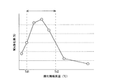
- FIG. 2 is a graph showing the relationship between the bed temperature of the oxidation catalyst 5 and the NOx purification rate when an appropriate amount of fuel is supplied to the oxidation catalyst 5.
- the bed temperature of the oxidation catalyst 5 is lower than the temperature Td1
- the NOx purification rate becomes low because the oxidation ability of the oxidation catalyst 5 is low.
- the bed temperature is the temperature Td2 (e.g., about 280 ° C.) becomes higher than, although oxidation ability of the oxidation catalyst 5 becomes sufficiently high, because the oxidation reaction 1 which the fuel is oxidized occurs dominantly, reduction of NO 2 The reaction is suppressed and the NOx purification rate is lowered. That is, when the catalyst temperature is in the temperature range from the temperature Td1 to the temperature Td2, that is, when the catalyst temperature belongs to a predetermined temperature range equal to or higher than the activation temperature Td1, the oxidation catalyst 5 removes NOx in the exhaust gas. It can reduce effectively. Therefore, in order to effectively exhibit the NOx purification ability of the oxidation catalyst 5, when the bed temperature of the oxidation catalyst 5 is within this temperature range, control for supplying an appropriate amount of fuel may be performed.
- Td2 e.g., about 280 ° C.
- FIG. 3 is a graph showing the relationship between the NOx purification rate of the SCR catalyst 10 and the bed temperature. Further, in FIG. 3, a broken line (the ratio of the amount of substance of NO 2 to the total amount of substance of NO and NO 2) NO 2 ratio in the exhaust represents the NOx purification rate when 50%, solid line and one point The chain lines indicate the NOx purification rates when the NO 2 ratio is 40% and 30%, respectively.
- the bed temperature of the SCR catalyst 10 when the bed temperature of the SCR catalyst 10 is equal to or lower than the temperature Ts1 (for example, about 150 ° C.), the SCR catalyst 10 is in an inactive state and the NOx purification rate is low.
- the bed temperature is equal to or higher than the temperature Ts2 (for example, about 200 ° C.)
- the SCR catalyst 10 when the bed temperature is equal to or higher than the temperature Ts2 (for example, about 200 ° C.), the SCR catalyst 10 is in an active state and the NOx purification rate is high. Note that, in any state of the inactive state and the active state, the influence of the NO 2 ratio in the exhaust on the NOx purification rate of the SCR catalyst 10 is generally small.
- the temperature Ts2 corresponds to the activation temperature of the SCR catalyst 10.
- the SCR catalyst 10 is in a transient state between the active state and the inactive state when the bed temperature is in the temperature range from the temperature Ts1 to the temperature Ts2.
- the NOx purification rate of the SCR catalyst 10 in a transient state tends to increase with increasing temperature, and varies according to the NO 2 ratio.
- the NOx purification rate of the SCR catalyst 10 in a transient state is higher as the NO 2 ratio is closer to 50%. This is because, in the SCR catalyst 10 in the transient state, the reduction reaction 4 shown in the reaction formula (4) in which NO and NO 2 react at a ratio of 1: 1 occurs predominantly. NO + NO 2 + 2NH 3 ⁇ 2N 2 + 3H 2 O (4)
- the ratio of NO to NO 2 in the SCR catalyst 10 is 1: 1, that is, the NO 2 ratio is closer to 50%, the reduction reaction 4 is promoted, so the NOx purification rate of the SCR catalyst 10 is increased. Therefore, when the SCR catalyst 10 is in a transitional state, the NO 2 purification rate of the SCR catalyst 10 is adjusted by bringing the NO 2 ratio of the exhaust gas flowing into the SCR catalyst 10 close to a predetermined ratio that promotes the reduction reaction 4. Can be increased to a predetermined purification rate when the NO 2 ratio is 50%.
- the amount of fuel supplied to the oxidation catalyst 5 is appropriately controlled and the NO 2 ratio of the exhaust gas flowing out from the oxidation catalyst 5 (that is, the exhaust gas flowing into the SCR catalyst 10) is brought close to the predetermined ratio, It is possible to increase the temperature of the SCR catalyst 10 while increasing the NOx purification rate of the exhaust gas flowing into the SCR catalyst 10 in a transient state to a predetermined purification rate.
- the fuel supply control is control of the amount of fuel supplied from the fuel injection valve 2 or the fuel addition valve 4 that is executed by the ECU 20 as a control unit in the present embodiment.
- FIG. 4 shows the fuel executed by the ECU 20 when the bed temperature of the oxidation catalyst 5 is equal to or higher than the temperature Td1 that is the activation temperature and the bed temperature of the SCR catalyst 10 is equal to or less than the temperature Ts2 that is the activation temperature. It is a figure explaining the control mode of supply control. As shown in FIG. 4, when the bed temperature of the oxidation catalyst 5 is lower than the temperature Td1, the supplied fuel may flow out without being sufficiently oxidized.
- Td1 the temperature
- Ts2 the temperature
- the bed temperature of the oxidation catalyst 5 belongs to the temperature range from the temperature Td1 and the temperature Td2, and the bed temperature of the SCR catalyst 10 is equal to or lower than the temperature Ts1, the oxidation catalyst 5 is in a state where it can exhibit the NOx purification ability. In contrast, the SCR catalyst 10 is in an inactive state.
- the “HC-SCR mode” is executed by the ECU 20. As described above, this control mode is a mode in which the fuel supply amount is controlled so that the reduction of NOx by the oxidation catalyst 5 is performed.
- the amount of fuel supplied at the time of execution of this control mode is an amount determined based on the bed temperature of the oxidation catalyst 5 or the like, and may be obtained in advance through experiments or the like.
- This control mode corresponds to the first control in the present invention.
- This control mode is a mode in which the fuel supply amount is controlled so as to increase the exhaust gas temperature flowing into the SCR catalyst 10 by the oxidation of the fuel by the oxidation catalyst 5 regardless of the NOx purification rate by the SCR catalyst 10.
- the amount of fuel supplied when this control mode is executed is determined based on the amount of air detected by the air flow meter 13, the bed temperature of the SCR catalyst 10, etc., and can be obtained in advance by experiments or the like. That's fine.
- This control mode corresponds to the second control in the present invention.
- the bed temperature of the oxidation catalyst 5 is equal to or higher than the temperature Td1
- the oxidation catalyst 5 is in a state where it can exhibit the NOx purification ability.
- the SCR catalyst 10 is in a transient state.
- the “NO 2 guarded SCR temperature increase mode” is executed by the ECU 20 .
- the ratio of NO and NO 2 in the exhaust gas flowing into the SCR catalyst 10 is set to a predetermined ratio with the NOx purification rate of the SCR catalyst 10 in a transient state as a predetermined purification rate, and the oxidation catalyst 5
- the fuel supply amount is controlled so that the exhaust temperature flowing into the SCR catalyst 10 rises due to the oxidation of the fuel.
- the temperature of the SCR catalyst 10 can be raised and the NOx purification rate can be increased while the NOx purification rate of the SCR catalyst 10 in a transient state is brought close to the predetermined purification rate.
- the amount of fuel supplied when this control mode is executed is an amount determined based on the amount of air detected by the air flow meter 13, the amount of fuel injected by the fuel injection valve 2, etc. Can be obtained in advance.
- This control mode corresponds to the third control in the present invention.
- FIG. 5 is a flowchart showing a control flow executed by the ECU 20. This control flow is periodically executed when the internal combustion engine 1 is operated.
- the ECU 20 acquires the bed temperature of the oxidation catalyst 5 and the bed temperature of the SCR catalyst 10 at the time of execution of the current control flow in step S101.
- the bed temperature of the oxidation catalyst 5 and the bed temperature of the SCR catalyst 10 are estimated from the exhaust temperatures detected by the first exhaust temperature sensor 6 and the second exhaust temperature sensor 12, respectively.
- step S102 the ECU 20 determines whether the bed temperature of the oxidation catalyst 5 is equal to or higher than the temperature Td1. If a negative determination is made in this step, the ECU 20 proceeds to step S103, prohibits fuel supply, and ends this routine.
- step S102 the ECU 20 proceeds to step S104, and determines whether the bed temperature of the SCR catalyst 10 is equal to or lower than the temperature Ts2. If a negative determination is made in this step, it is considered that the SCR catalyst 10 is already in an active state and the NOx purification rate is sufficiently high. Therefore, the ECU 20 ends this flow without executing fuel supply for the purpose of increasing the NOx purification rate of the exhaust purification device.
- step S104 the ECU 20 proceeds to step S105, and determines whether the bed temperature of the SCR catalyst 10 is equal to or higher than the temperature Ts1. If a negative determination is made in this step, the ECU 20 proceeds to step S106 and determines whether the bed temperature of the oxidation catalyst 5 is equal to or lower than the temperature Td2.
- step S106 When an affirmative determination is made in step S106, the bed temperature of the oxidation catalyst 5 belongs to the temperature range from the temperature Td1 and the temperature Td2 and the bed temperature of the SCR catalyst 10 is higher than the temperature Ts1, together with the previous determination result. Means low. Therefore, the ECU 20 proceeds to step S107, executes the HC-SCR mode, and increases the NOx purification rate of the oxidation catalyst 5. When step S107 is executed, this flow ends.
- step S106 determines whether the bed temperature of the oxidation catalyst 5 is higher than the temperature Td2 and the bed temperature of the SCR catalyst 10 is lower than the temperature Ts1, together with the previous determination result. . Therefore, the ECU 20 proceeds to step S108 and executes the SCR temperature increase mode without NO 2 guard. Thereby, the NOx purification rate of the SCR catalyst 10 increases. When step S108 is executed, this flow ends.
- step S105 If an affirmative determination is made in step S105, the bed temperature of the oxidation catalyst 5 is equal to or higher than the temperature Td1 and the bed temperature of the SCR catalyst 10 is between the temperature Ts1 and the temperature Ts2 in combination with the previous determination result. It means that it is in the temperature range. That is, the SCR catalyst 10 is in a transient state. Therefore, the ECU 20 proceeds to step S109 and executes the SCR temperature increase mode with NO 2 guard. Thereby, the temperature of the SCR catalyst 10 can be raised and the NOx purification rate can be increased while the NOx purification rate of the SCR catalyst 10 in a transient state is brought close to the predetermined purification rate. When step S109 is executed, this flow ends.
- the control mode of the fuel supply control is selected and executed based on the bed temperatures of the oxidation catalyst 5 and the SCR catalyst 10. Therefore, it is possible to appropriately supply the fuel so that the NOx purification rate of the catalyst that exhibits more NOx purification ability is increased. As a result, it is possible to increase the NOx purification rate of the entire exhaust purification device.
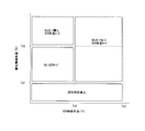
- FIG. 6 is a diagram illustrating a control mode of fuel supply control executed by the ECU 20 in the second embodiment.
- the oxidation is performed when the SCR catalyst 10 is in a transient state and the HC-SCR mode is executed.
- the HC is changed to the SCR temperature increase mode with the NO 2 guard. -The SCR mode is executed.
- both the oxidation catalyst 5 and the SCR catalyst 10 supply an appropriate amount of fuel. Then, the NOx reducing ability can be effectively exhibited.
- the control since it is possible to selectively execute the control that is predicted to increase the NOx purification rate of the oxidation catalyst 5, it is possible to reliably increase the NOx purification rate of the entire exhaust purification device. it can. This prediction may be performed based on the bed temperature of the oxidation catalyst 5 estimated by the ECU 20, the bed temperature of the SCR catalyst 10, or the like.
- the bed temperature of the SCR catalyst 10 is closer to the temperature Ts1, the NOx purification rate of the SCR catalyst 10 becomes lower. Therefore, the bed temperature of the oxidation catalyst 5 and the bed temperature of the SCR catalyst 10 are within the region A shown in FIG. In some cases, the NOx purification rate of the oxidation catalyst 5 is predicted to be higher than the NOx purification rate of the SCR catalyst 10.
- the SCR temperature increase mode with NO 2 guard is executed, and the SCR in case the bed temperature of the catalyst 10 is higher than the temperature Ts2, also, NO 2 guard there SCR heating mode when the bed temperature of the SCR catalyst 10 by bed temperature of the oxidation catalyst 5 is expected to shift the transient state decreases Is executed.
- the bed temperature of the SCR catalyst 10 When the bed temperature of the SCR catalyst 10 is equal to or higher than the temperature Ts2, the bed temperature of the oxidation catalyst 5 is sufficiently lower than the bed temperature of the SCR catalyst 10 even when the SCR catalyst 10 is in an active state.
- the low temperature exhaust gas flowing out from the oxidation catalyst 5 may flow into the SCR catalyst 10 disposed on the downstream side to lower the bed temperature of the SCR catalyst 10. Thereby, the bed temperature of the SCR catalyst 10 may fall below the temperature Ts2, and the SCR catalyst 10 may shift to a transient state.
- the bed temperature of the oxidation catalyst 5 estimated by the ECU 20 is sufficiently lower than the bed temperature of the SCR catalyst 10 (for example, the bed temperature of the oxidation catalyst 5 and the bed temperature of the SCR catalyst 10 are shown in FIG. In the region B), it is predicted that the bed temperature of the SCR catalyst 10 is lowered by the bed temperature of the oxidation catalyst 5 and transitions to a transient state.
- the SCR temperature rising mode with NO 2 guard is executed in advance.
- the NOx purification rate of the SCR catalyst 10 is prevented from decreasing after the transition to the transient state.
- the bed temperature of the oxidation catalyst 5 when the bed temperature of the oxidation catalyst 5 is equal to or higher than the temperature Td1, the bed temperature of the SCR catalyst 10 is increased by the bed temperature of the oxidation catalyst 5 when the SCR catalyst 10 is in a transient state.
- the SCR temperature rising mode with NO 2 guard is prohibited.
- the bed temperature of the SCR catalyst 10 is in the range from the temperature Ts1 to the temperature Ts2, even when the SCR catalyst 10 is in a transient state, the bed temperature of the oxidation catalyst 5 is compared with the bed temperature of the SCR catalyst 10.
- the bed temperature of the SCR catalyst 10 is expected to rise due to the high-temperature exhaust gas flowing out from the oxidation catalyst 5 flowing into the SCR catalyst 10. That is, the bed temperature of the oxidation catalyst 5 estimated based on the output signal from the first exhaust temperature sensor 6 is compared with the bed temperature of the SCR catalyst 10 estimated based on the output signal from the second exhaust temperature sensor 12.
- the bed temperature of the SCR catalyst 10 depends on the bed temperature of the oxidation catalyst 5. Is expected to shift to an active state. According to the present embodiment, in such a case, the SCR temperature increase mode with NO 2 guard is prohibited, so that the fuel supply amount can be reduced.
Landscapes
- Engineering & Computer Science (AREA)
- Chemical & Material Sciences (AREA)
- Chemical Kinetics & Catalysis (AREA)
- Combustion & Propulsion (AREA)
- Mechanical Engineering (AREA)
- General Engineering & Computer Science (AREA)
- Health & Medical Sciences (AREA)
- Toxicology (AREA)
- Materials Engineering (AREA)
- Exhaust Gas After Treatment (AREA)
- Exhaust Gas Treatment By Means Of Catalyst (AREA)
Abstract
排気通路に酸化触媒と選択還元型触媒とが設けられた内燃機関の排気浄化装置において、排気浄化装置全体のNOx浄化率を上昇させる。酸化触媒への燃料供給量を制御する制御部が、酸化触媒の温度がその活性温度以上の所定の温度範囲に属する場合において、選択還元型触媒が非活性状態となるときには、酸化触媒によるNOxの還元が行われるように燃料供給量を制御する第1制御を実行し、酸化触媒の温度が所定の温度範囲を超える場合において、選択還元型触媒が非活性状態となるときには、選択還元型触媒によるNOx浄化率に関わらず、酸化触媒による燃料の酸化によって選択還元型触媒に流入する排気温度を上昇させるように燃料供給量を制御する第2制御を実行する。
Description
本発明は、排気通路に酸化触媒と選択還元型触媒とが設けられた内燃機関の排気浄化装置に関する。
従来、内燃機関の排気通路に、酸化能を有する酸化触媒と、この酸化触媒よりも下流側に、排気内の窒素酸化物(NOx)を選択還元する選択還元型触媒(SCR触媒)とを備える排気浄化装置が知られている。酸化触媒は、内燃機関から排出される未燃の燃料や一酸化酸素を浄化したり、供給装置から供給される燃料を酸化して排気温度を上昇させたりすることができる。なお、酸化触媒は、排気内の燃料を還元剤として用いて排気内に含まれるNOxをある程度選択還元することができる。そこで、排気通路を流通する排気の温度が第1温度域にあるときは、酸化触媒でNOx浄化を行うために燃料を供給し、排気温度がこの第1温度域より高い第2温度域にあるときは、SCR触媒でNOx浄化を行うために尿素水を供給する技術が知られている(例えば、特許文献1参照)。
ところで、酸化触媒やSCR触媒のNOx浄化能は、実際には触媒温度(床温)に依存する。排気温度の変化は触媒の床温変化と常に一致するわけではないため、排気温度に基づいて酸化触媒への燃料供給とSCR触媒への尿素水供給とを使い分ける特許文献1に記載の技術では、還元剤の供給を各触媒の床温に応じて適切に行うことは難しい。その結果、各触媒においてNOx浄化能が有効に発揮されない虞がある。
本発明は、このような実情に鑑みてなされたものであり、排気通路に酸化触媒とSCR触媒とが設けられた内燃機関の排気浄化装置において、排気浄化装置全体のNOx浄化率を上昇させることを目的とする。
上記した課題を解決するために、本発明に係る内燃機関の排気浄化装置は、
内燃機関の排気通路に設けられ、酸化能を有する酸化触媒であって、更に、触媒温度がその活性温度以上の所定の温度範囲に属するときに、排気を介して供給された燃料を還元剤として用いることで排気中のNOxを還元する酸化触媒と、
前記酸化触媒に流入する排気を介して該酸化触媒に燃料を供給する燃料供給部と、
前記排気通路における前記酸化触媒より下流側に設けられ、アンモニアを還元剤として用いることで排気中のNOxを還元する選択還元型触媒と、
前記選択還元型触媒に流入する排気を介して該選択還元型触媒にアンモニアまたはアンモニアの前駆体を供給する還元剤供給部と、
前記燃料供給部による燃料供給量を制御する制御部と、
を備える内燃機関の排気浄化装置であって、
前記制御部は、
前記酸化触媒の温度が前記所定の温度範囲に属する場合において、前記選択還元型触媒が非活性状態となるときには、該酸化触媒によるNOxの還元が行われるように、前記燃料供給部による燃料供給量を制御する第1制御と、
前記酸化触媒の温度が前記所定の温度範囲を超える場合において、前記選択還元型触媒が非活性状態となるときには、前記選択還元型触媒によるNOx浄化率に関わらず、該酸化触媒による燃料の酸化によって該選択還元型触媒に流入する排気温度を上昇させるように、前記燃料供給部による燃料供給量を制御する第2制御と、
を実行するようにした。
酸化触媒は、触媒温度が所定の活性温度以上になると、十分な酸化能を発揮して排気内の燃料や一酸化炭素を酸化することができる。なお、酸化触媒は、触媒温度がこの活性温度以上の所定の温度範囲に属するときには、更に、排気を介して供給された燃料を還元剤として用いて排気中のNOxをある程度還元することができる。
一方、選択還元型触媒(SCR触媒)は、アンモニアを還元剤として用いることで、排気内のNOxを還元する。一般に、内燃機関の排気浄化装置においては、還元によるNOxの浄化はSCR触媒によって主に行われる。SCR触媒は、触媒温度が高温側の所定の閾温度以上になると、NOx浄化率の高い活性状態になる。一方、SCR触媒は、触媒温度が低温側の所定の閾温度以下になると、NOx浄化率の低い非活性状態となる。
そこで、本発明の制御部は、酸化触媒の温度がその活性温度以上の所定の温度範囲に属する場合において、SCR触媒が非活性状態となるときには、該酸化触媒によるNOxの還元が行われるように、燃料供給部による燃料供給量を制御する第1制御を実行する。これにより、SCR触媒のNOx浄化能が低いときであっても、NOx浄化能が発揮される状態にある酸化触媒に燃料が供給されることによって、酸化触媒によるNOxの還元が促進される。その結果、排気浄化装置のNOx浄化能を可及的に確保することができる。
また、本発明の制御部は、酸化触媒の温度が当該所定の温度範囲を超える場合において、SCR触媒が非活性状態となるときには、SCR触媒によるNOx浄化率に関わらず、該酸化触媒による燃料の酸化によって該選択還元型触媒に流入する排気温度を上昇させるように、燃料供給部による燃料供給量を制御する第2制御を実行する。このときには、酸化触媒の触媒温度が高いために、酸化触媒によるNOxの還元を期待することはできないが、酸化触媒による燃料の酸化能は十分に高くなっている。そこで、SCR触媒によるNOx浄化率に関わらず、該酸化触媒による燃料の酸化によって該選択還元型触媒に流入する排気温度を上昇させるように燃料を供給することで、SCR触媒の昇温に特化した燃料の供給を行うことができる。その結果、SCR触媒をより速やかに活性状態に移行させることができるため、NOx浄化能の高いSCR触媒のNOx浄化率を早期に上昇させて、排気浄化装置のNOx浄化能を可及的に確保することができる。
以上より、本発明によれば、酸化触媒の温度がその活性温度以上の場合において、SCR触媒が非活性状態となるときには、酸化触媒の温度に応じて、よりNOx浄化能が発揮される触媒のNOx浄化率が上昇するように、燃料供給部による燃料供給量が制御される。ゆえに、排気浄化装置全体のNOx浄化率を上昇させることができる。
なお、SCR触媒は、その触媒温度が上述の高温側の所定の閾温度と低温側の所定の閾温度で定まる温度範囲内にあるときは、活性状態と非活性状態との間の過渡状態になる。SCR触媒が過渡状態にある場合には、SCR触媒のNOx浄化率と触媒温度との間には相関関係があり、触媒温度が高くなるとSCR触媒のNOx浄化率が高くなる。ただし、このときのNOx浄化率は、活性状態のときのそれ以下になる。また、SCR触媒が過渡状態にある場合には、NOx浄化率と、SCR触媒に流入する排気中の一酸化窒素(NO)と二酸化窒素(NO2)の比率(NO2比率)との間にも相関関係がある。具体的には、SCR触媒が過度状態にある場合は、SCR触媒内の排気中のNO2比率が50%に近付くほど、特定のNOxの還元反応が促進されることによってNOx浄化率が高くなる。ここで、SCR触媒内の排気のNO2比率が特定の比率(例えば50%)のときにおけるSCR触媒のNOx浄化率を所定浄化率とすると、SCR触媒内におけるNO2比率は、SCR触媒に流入する排気のNO2比率から変化し得るため、SCR触媒のNOx浄化率を所定浄化率とすることのできる、SCR触媒に流入する排気のNO2比率を所定の比率として定めることができる。
そこで、本発明の制御部は、酸化触媒の温度がその活性温度以上の場合において、SCR触媒が過渡状態となるときには、該SCR触媒に流入する排気中のNO2比率を、過渡状態にあるSCR触媒のNOx浄化率を上述の所定浄化率とする所定の比率としながら、該酸化触媒による燃料の酸化によって該SCR触媒に流入する排気温度を上昇させるように、燃料供給部による燃料供給量を制御する第3制御を実行するようにしてもよい。これにより、過渡状態にあるSCR触媒のNOx浄化率を可及的に高くしながら、SCR触媒を昇温させて速やかに活性状態に移行させることが可能になる。その結果、SCR触媒のNOx浄化率を早期に上昇させて、排気浄化装置のNOx浄化能を可及的に確保することができる。
また、本発明の制御部は、酸化触媒の温度がその活性温度以上の場合において、SCR触媒が過渡状態となるときであって、第1制御が実行されるときの酸化触媒のNOx浄化率が、第3制御が実行されるときの選択還元型触媒のNOx浄化率より高いと予測されるときは、第3制御に替えて第1制御を実行するようにしてもよい。これにより、酸化触媒のNOx浄化率がより上昇すると予測される制御を選択的に実行することが可能になるため、排気浄化装置全体のNOx浄化率を確実に上昇させることができる。
また、本発明の制御部は、酸化触媒の温度がその活性温度以上の場合において、SCR触媒が過渡状態となるときにおける第3制御の実行に加えて、SCR触媒の温度がその活性温度より高い場合に、酸化触媒の温度によりSCR触媒の温度が低下して過渡状態に移行すると予測されるときにも第3制御を実行するようにしてもよい。例えば、酸化触媒の温度がSCR触媒の温度に比して十分に低いときは、酸化触媒から流出する低温の排気が下流側に配置されたSCR触媒に流入してSCR触媒の温度を低下させる虞がある。これにより、SCR触媒の温度が過渡状態となる温度まで低下することによって、SCR触媒のNOx浄化率が低下する可能性がある。本発明によれば、このような場合には、第3制御が予め実行されるため、過渡状態への移行後においてSCR触媒のNOx浄化率が低下することが未然に抑制される。
また、本発明の制御部は、酸化触媒の温度がその活性温度以上の場合において、SCR触媒が過渡状態となるときであって、酸化触媒の温度によりSCR触媒の温度が上昇して活性状態に移行すると予測されるときは、第3制御を禁止するようにしてもよい。例えば、酸化触媒の温度が、SCR触媒の温度に比して十分に高いときは、酸化触媒から流出される高温の排気がSCR触媒に流入することによってSCR触媒の温度が上昇すると予測される。つまり、SCR触媒の昇温を実行しなくても、SCR触媒の温度が上昇して活性状態に移行すると予測される。本発明によれば、このような場合には第3制御を禁止するため、燃料供給量を低減させることが可能になる。
本発明によれば、排気通路に酸化触媒とSCR触媒とが配置された内燃機関の排気浄化装置において、酸化触媒とSCR触媒の温度に応じて、よりNOx浄化能が発揮される触媒のNOx浄化率が上昇するように、燃料供給部による燃料供給量が制御されるため、排気浄化装置全体のNOx浄化率を上昇させることができる。
以下、本発明の具体的な実施形態について図面に基づいて説明する。本実施形態に記載される構成部品の寸法、材質、形状、相対配置等は、特に記載がない限り発明の技術的範囲をそれらのみに限定する趣旨のものではない。
[実施例1]
まず、本発明の第1の実施例に係る内燃機関の排気浄化装置の構成について説明する。図1は、本発明が適用される内燃機関とその吸排気系の概略構成を示す図である。図1に示す内燃機関1は、複数の気筒を有する自動車用の圧縮着火式の内燃機関(ディーゼルエンジン)である。なお、本発明を適用する内燃機関は、圧縮着火式の内燃機関に限られず、火花点火式の内燃機関(ガソリンエンジン)であってもよい。
まず、本発明の第1の実施例に係る内燃機関の排気浄化装置の構成について説明する。図1は、本発明が適用される内燃機関とその吸排気系の概略構成を示す図である。図1に示す内燃機関1は、複数の気筒を有する自動車用の圧縮着火式の内燃機関(ディーゼルエンジン)である。なお、本発明を適用する内燃機関は、圧縮着火式の内燃機関に限られず、火花点火式の内燃機関(ガソリンエンジン)であってもよい。
内燃機関1は、気筒内へ燃料を噴射する燃料噴射弁2を備えている。また、内燃機関1には、内燃機関1の気筒内から排出される排気を流通させるための排気通路3が接続されている。排気通路3には、上流側から順に、燃料添加弁4、酸化触媒5、第1排気温度センサ6、DPF7、尿素水添加弁8、第1NOxセンサ9、選択還元型触媒10(以下、「SCR触媒10」という)、第2NOxセンサ11及び第2排気温度センサ12が配置されている。燃料供給部としての燃料添加弁4は、排気通路3内を流通する排気に燃料を噴射し、酸化触媒5に燃料を供給する。なお、燃料噴射弁2によって、気筒内で燃焼が発生した後に燃料を噴射するアフター噴射やポスト噴射を行って、酸化触媒5に燃料を供給してもよい。この場合には、燃料噴射弁2が本実施例における燃料供給部に相当する。
酸化触媒5は、内燃機関1から排出される未燃の燃料や一酸化炭素(CO)等を酸化し、これらが大気へ排出されることを抑制する。また、酸化触媒5は、燃料噴射弁2や燃料添加弁4によって供給された燃料を酸化して排気温度を上昇させる。排気温度の上昇は、例えばDPF7の再生処理の実行時に行われる。なお、酸化触媒5は、触媒温度がその活性温度以上の所定の温度範囲に属するときには、燃料を還元剤として用いる選択還元によって、内燃機関1から排出されたNOxを浄化することもできる(詳細は後述)。
SCR触媒10は、アンモニアを用いて排気中のNOxを窒素(N2)に選択還元してNOxの浄化を行う。内燃機関1においては、NOxの浄化はSCR触媒10によって主に行われる。つまり、活性状態にあるSCR触媒10のNOx浄化能は、酸化触媒5によって発揮される浄化能よりも高い。SCR触媒10は、筒状のケーシング内に、流入したアンモニアを吸着する機能を有する触媒担体を収容している。この触媒担体は、コーディライトやFe-Cr-Al系の耐熱鋼から成るハニカム形状の横断面を有する基材に、アルミナ系またはゼオライト系の活性成分(担体)がコーティングされたものである。なお、本実施例においては、DPF7とSCR触媒10を別々に設けているが、両者が一体化されたSCR触媒を用いてもよい。
SCR触媒10より上流側の排気通路3には、排気通路3内を流通する排気にアンモニアの前駆体としての尿素((NH2)2CO)が溶解された尿素水を添加する尿素水添加弁8が配置されている。尿素水添加弁8は、ポンプ80を介して尿素水タンク81に接続されており、尿素水タンク81からポンプ80によって圧送されてくる尿素水を排気通路3内へ噴射する。噴射された尿素水は、排気の熱による加水分解反応によってアンモニアを発生する。このようにして発生したアンモニアがSCR触媒10において還元剤として消費される。なお、尿素水の替わりにアンモニアが溶解されたアンモニア水を添加するようにしてもよい。
以上のように構成された内燃機関1には、内燃機関1を制御するための電子制御ユニットであるECU20が併設されている。ECU20は、燃料噴射弁2、燃料添加弁4、尿素水添加弁8、ポンプ80等の各種機器と電気的に接続されており、これらを電気的に制御する。また、ECU20は、第1排気温度センサ6、第1NOxセンサ9、第2NOxセンサ11、第2排気温度センサ12、エアフローメータ13、回転計14等の各種センサと電気的に接続されている。
第1排気温度センサ6は、排気通路3における酸化触媒5の下流側に配置され、酸化触媒5から流出する排気の温度に相関する電気信号を出力する。ECU20は、第1排気温度センサ6から出力された電気信号を用いて、酸化触媒5の触媒温度(床温)を推定する。また、第2排気温度センサ12は、排気通路3におけるSCR触媒10の下流側に配置され、SCR触媒10から流出する排気の温度に相関する電気信号を出力する。ECU20は、第2排気温度センサ12から出力された電気信号を用いて、SCR触媒10の床温を推定する。
また、第1NOxセンサ9は、排気通路3におけるSCR触媒10の上流側に配置され、SCR触媒10に流入する排気内のNOx濃度に相関する電気信号を出力する。また、第2NOxセンサ11は、排気通路3におけるSCR触媒10の下流側に配置され、SCR触媒10から流出する排気内のNOx濃度に相関する電気信号を出力する。ECU20は、これら2つのNOxセンサから出力された電気信号を用いて、SCR触媒10のNOx浄化率を推定する。
また、エアフローメータ13は、内燃機関1の吸気通路に配置され、内燃機関1に吸入される吸気量に相関する電気信号を出力する。ECU20は、エアフローメータ13から出力された電気信号を用いて、内燃機関1の気筒内に吸入される酸素量を算出する。更に、ECU20は、算出された酸素量や、燃料噴射弁2によって噴射される燃料量、回転計14によって検出される内燃機関1の機関回転数等を用いて、内燃機関1から排出されるNOx量、すなわち、酸化触媒5に流入するNOx量を推定する。
次に、本実施例に係る酸化触媒5の触媒機能について説明する。酸化触媒5は、床温が活性温度としての所定の温度Td1(例えば、150℃)以上になると、触媒が活性化されて、次の反応式1で示される酸化反応1によって燃料(炭化水素HC)を酸化する。
2HC+5/2O2→2CO2+H2O (1)
2HC+5/2O2→2CO2+H2O (1)
この酸化反応は発熱反応である。そのため、SCR触媒10の昇温や、DPF7の再生処理が実行される際には、酸化触媒5から流出する排気の温度を上昇させるために、酸化触媒5への燃料供給が実行される。
一方、酸化触媒5は、SCR触媒10には劣るものの、燃料を還元剤として用いてNOxをある程度選択還元することができる。より詳細には、酸化触媒5は、燃料に含まれる炭化水素(例えば、プロピレン(C3H6))を還元剤として用いて、次の反応式2で示される還元反応2によって、NOx中のNO2を選択還元することができる。
NO2+2/9C3H6→1/2N2+2/3CO2+2/3H2O (2)
NO2+2/9C3H6→1/2N2+2/3CO2+2/3H2O (2)
なお、内燃機関1から排出される排気内のNOxの中では、NOの割合が最も高い。そのため、酸化触媒5においてNOxが効果的に浄化されるためには、その前提として、酸化触媒5において次の反応式3で示されるNOの酸化反応3が促進されて、還元反応2に供されるNO2が生成されることが必要になる。
2NO+O2→2NO2 (3)
2NO+O2→2NO2 (3)
酸化触媒5に供給された燃料は、酸化反応1と還元反応2に供される。ただし、酸化触媒5においては、酸化反応1の方が生じやすいため、供給された燃料は酸化反応1によって優先的に消費される。そのため、燃料の供給量によっては、酸化反応1が過度に促進される可能性がある。酸化触媒5の酸化能は、床温が一定のときには一定であり、また、排気内の酸素には限りがあるため、酸化反応1が過度に促進されることによって酸素が消費されると、酸化反応3が抑制される可能性がある。酸化反応3が抑制されると、酸化反応3によって生成されるNO2の量が減少するため、還元反応2が抑制されることになり、結果的に酸化触媒5のNOx浄化能が低下する虞がある。そのため、酸化触媒5によってNOxが効果的に浄化されるためには、酸化触媒5に適切な量の燃料を供給する必要がある。
酸化触媒5に適切な量の燃料が供給された場合、酸化触媒5は、図2に示されるような特性を示す。なお、図2は、酸化触媒5に適切な量の燃料が供給されたときにおける酸化触媒5の床温とNOx浄化率との関係を示す図である。図2に示されるように、酸化触媒5の床温が温度Td1より低いときは、酸化触媒5の酸化能が低いためにNOx浄化率は低くなる。一方、床温が温度Td2(例えば、約280℃)より高くなると、酸化触媒5の酸化能が十分に高くなるものの、燃料が酸化される酸化反応1が支配的に生じるため、NO2の還元反応が抑制されてNOx浄化率は低くなる。つまり、酸化触媒5は、その触媒温度が温度Td1から温度Td2までの温度範囲内にあるとき、即ち、触媒温度がその活性温度Td1以上の所定の温度範囲に属するときに、排気中のNOxを効果的に還元することができる。そのため、酸化触媒5のNOx浄化能を効果的に発揮させるためには、酸化触媒5の床温がこの温度範囲にあるときに、適切な量の燃料を供給する制御を行えばよい。
次に、本実施例に係るSCR触媒10の触媒機能について図3を用いて説明する。なお、図3は、SCR触媒10のNOx浄化率と床温との関係を示す図である。また、図3においては、破線が排気内のNO2比率(NOとNO2の合計の物質量に対するNO2の物質量の比率)が50%のときのNOx浄化率を示し、実線及び1点鎖線が、それぞれNO2比率が40%のとき及び30%のときのNOx浄化率を示している。
図3に示されるように、SCR触媒10の床温が温度Ts1(例えば、約150℃)以下のときは、SCR触媒10は非活性状態にあって、NOx浄化率は低い。一方、床温が温度Ts2(例えば、約200℃)以上のときは、SCR触媒10は活性状態にあって、NOx浄化率は高い。なお、非活性状態と活性状態の何れの状態においても、排気内のNO2比率がSCR触媒10のNOx浄化率に与える影響は概ね小さい。なお、この温度Ts2が、SCR触媒10の活性温度に相当する。そして、SCR触媒10は、その床温が温度Ts1から温度Ts2までの温度範囲にあるときは、活性状態と非活性状態との間の過渡状態にある。過渡状態にあるSCR触媒10のNOx浄化率は、昇温に伴って高くなる傾向にあり、また、NO2比率に応じて変動する。
詳細には、図3に示されるように、過渡状態にあるSCR触媒10のNOx浄化率は、NO2比率が50%に近いほど高い。これは、過渡状態にあるSCR触媒10においては、NOとNO2が1:1の比率で反応する、反応式(4)に示される還元反応4が支配的に発生することに因る。
NO+NO2+2NH3→2N2+3H2O (4)
NO+NO2+2NH3→2N2+3H2O (4)
ゆえに、SCR触媒10内におけるNOとNO2の比率が1:1、すなわち、NO2比率が50%に近いほど、還元反応4が促進されるため、SCR触媒10のNOx浄化率が高くなる。したがって、SCR触媒10が過渡状態にあるときは、SCR触媒10に流入する排気のNO2比率を、還元反応4が促進されるような所定の比率に近付けることによって、SCR触媒10のNOx浄化率を、NO2比率が50%のときにおける所定の浄化率まで上昇させることができる。そのため、酸化触媒5に供給する燃料の量を適切に制御して、酸化触媒5から流出する排気(すなわち、SCR触媒10に流入する排気)のNO2比率を当該所定の比率に近付ければ、過渡状態にあるSCR触媒10に流入する排気のNOx浄化率を所定の浄化率まで上昇させながら、SCR触媒10の昇温を図ることができる。
次に、本実施例に係る排気浄化装置のNOx浄化率を上昇させるためにECU20が実行する燃料供給制御について、図4を用いて説明する。なお、燃料供給制御とは、本実施例における制御部としてのECU20によって実行される、燃料噴射弁2や燃料添加弁4から供給される燃料の量の制御である。また、図4は、酸化触媒5の床温がその活性温度である温度Td1以上の場合において、SCR触媒10の床温がその活性温度である温度Ts2以下のときに、ECU20によって実行される燃料供給制御の制御モードを説明する図である。なお、図4に示されるように、酸化触媒5の床温が温度Td1未満の場合には、供給された燃料が十分に酸化されずに流出する虞があるため、ECU20によって燃料供給が禁止される。
酸化触媒5の床温が温度Td1と温度Td2までの温度範囲に属する場合において、SCR触媒10の床温が温度Ts1以下のときは、酸化触媒5がNOx浄化能を発揮できる状態にあるのに対してSCR触媒10は非活性状態にある。このときには、図4に示されるように、ECU20によって、「HC-SCRモード」が実行される。この制御モードは、上述したように、酸化触媒5によるNOxの還元が行われるように燃料供給量が制御されるモードである。これにより、SCR触媒10のNOx浄化能が低いときであっても、NOx浄化能がより発揮される状態にある酸化触媒5によるNOxの還元が促進されるため、排気浄化装置のNOx浄化率が上昇する。ここで、この制御モードの実行時に供給される燃料の量は、酸化触媒5の床温等に基づいて定まる量であり、実験等によって予め求めておけばよい。なお、この制御モードが、本発明における第1制御に相当する。
酸化触媒5の床温が温度Td2より高い場合において、SCR触媒10の床温が温度Ts1以下のときは、酸化触媒5が排気内のNOxを効果的に浄化できない状態にあり、更に、SCR触媒10も非活性状態にある。ただし、このときには、酸化触媒5は、床温が高いために酸化能は高い。そのため、このときには、図4に示されるように、ECU20によって、「NO2ガード無しSCR昇温モード」が実行される。この制御モードは、SCR触媒10によるNOx浄化率に関わらず、酸化触媒5による燃料の酸化によってSCR触媒10に流入する排気温度を上昇させるように燃料供給量が制御されるモードである。これにより、SCR触媒10の昇温に特化した燃料の供給を行うことができる。その結果、SCR触媒10がより早期に昇温されるため、NOx浄化能の高いSCR触媒10のNOx浄化率を効果的に上昇させることができる。ここで、この制御モードの実行時に供給される燃料の量は、エアフローメータ13によって検出される空気量や、SCR触媒10の床温等に基づいて定まる量であり、実験等によって予め求めておけばよい。なお、この制御モードが、本発明における第2制御に相当する。
酸化触媒5の床温が温度Td1以上の場合において、SCR触媒10の床温が温度Ts1から温度Ts2までの範囲にあるときは、酸化触媒5がNOx浄化能を発揮できる状態にあるのに対してSCR触媒10は過渡状態にある。このときには、図4に示されるように、ECU20によって、「NO2ガード有りSCR昇温モード」が実行される。この制御モードは、SCR触媒10に流入する排気中のNOとNO2との比率を、過渡状態にあるSCR触媒10のNOx浄化率を所定浄化率とする所定の比率としながら、酸化触媒5による燃料の酸化によってSCR触媒10に流入する排気温度が上昇するように燃料供給量が制御されるモードである。これにより、過渡状態にあるSCR触媒10のNOx浄化率を所定浄化率に近付けながら、SCR触媒10を昇温させてNOx浄化率を上昇させることができる。ここで、この制御モードの実行時に供給される燃料の量は、エアフローメータ13によって検出される空気量や、燃料噴射弁2によって噴射される燃料噴射量等に基づいて定まる量であり、実験等によって予め求めておけばよい。なお、この制御モードが、本発明における第3制御に相当する。
次に、本実施例における燃料供給制御の実行手順について図5を用いて説明する。図5は、ECU20が実行する制御フローを示したフローチャートである。この制御フローは、内燃機関1の運転時に周期的に実行される。
本制御フローが開始されると、ECU20は、ステップS101において、今回の制御フロー実行時における酸化触媒5の床温とSCR触媒10の床温を取得する。上述のように、酸化触媒5の床温及びSCR触媒10の床温は、それぞれ第1排気温度センサ6及び第2排気温度センサ12に検出される排気温度から推定される。
次に、ECU20は、ステップS102において、酸化触媒5の床温が温度Td1以上であるかを判定する。本ステップにおいて否定判定がなされた場合、ECU20は、ステップS103に進んで燃料供給を禁止して、本ルーチンを終了する。
ステップS102において肯定判定が下された場合、ECU20は、ステップS104に進み、SCR触媒10の床温が温度Ts2以下であるかを判定する。本ステップにおいて否定判定がなされた場合は、SCR触媒10は既に活性状態にあって、NOx浄化率が十分に高いと考えられる。そこで、ECU20は、排気浄化装置のNOx浄化率の上昇を目的とした燃料供給を実行せずに本フローを終了する。
一方、ステップS104において肯定判定が下された場合、ECU20は、ステップS105に進み、SCR触媒10の床温が温度Ts1以上であるかを判定する。本ステップにおいて否定判定がなされた場合、ECU20は、ステップS106に進んで酸化触媒5の床温が温度Td2以下であるかを判定する。
ステップS106で肯定判定がなされた場合は、以前の判定結果と合わせて、酸化触媒5の床温が温度Td1と温度Td2までの温度範囲に属し、且つ、SCR触媒10の床温が温度Ts1より低いことを意味する。そこで、ECU20は、ステップS107に進んで、HC-SCRモードを実行して酸化触媒5のNOx浄化率を上昇させる。ステップS107が実行されると、本フローは終了される。
一方、ステップS106で否定判定がなされた場合は、以前の判定結果と合わせて、酸化触媒5の床温が温度Td2より高く、且つ、SCR触媒10の床温が温度Ts1より低いことを意味する。そこで、ECU20は、ステップS108に進んで、NO2ガード無しSCR昇温モードを実行する。これにより、SCR触媒10のNOx浄化率が上昇する。ステップS108が実行されると、本フローは終了される。
なお、ステップS105において肯定判定がなされた場合は、以前の判定結果と合わせて、酸化触媒5の床温が温度Td1以上であり、且つ、SCR触媒10の床温が温度Ts1と温度Ts2までの温度範囲にあることを意味する。つまり、SCR触媒10は過渡状態にある。そこで、ECU20は、ステップS109に進んでNO2ガード有りSCR昇温モードを実行する。これにより、過渡状態にあるSCR触媒10のNOx浄化率を所定浄化率に近付けながら、SCR触媒10を昇温させてNOx浄化率を上昇させることができる。ステップS109が実行されると、本フローは終了される。
以上より、本実施例によれば、酸化触媒5の床温が活性温度以上の場合において、酸化触媒5とSCR触媒10の床温に基づいて、燃料供給制御の制御モードを選択して実行するため、よりNOx浄化能が発揮される触媒のNOx浄化率が上昇するように適切に燃料供給を行うことができる。その結果、排気浄化装置全体のNOx浄化率を上昇させることが可能になる。
[実施例2]
次に、本発明の変形例としての実施例2について説明する。本実施例に係る内燃機関及び排気浄化装置の概略構成は実施例1と同様である。以下、本実施例に係る燃料供給制御について、実施例1とは異なる点を中心に図6を用いて説明する。なお、図6は、実施例2においてECU20によって実行される燃料供給制御の制御モードを説明する図である。
次に、本発明の変形例としての実施例2について説明する。本実施例に係る内燃機関及び排気浄化装置の概略構成は実施例1と同様である。以下、本実施例に係る燃料供給制御について、実施例1とは異なる点を中心に図6を用いて説明する。なお、図6は、実施例2においてECU20によって実行される燃料供給制御の制御モードを説明する図である。
本実施例においては、酸化触媒5の床温が温度Td1から温度Td2までの範囲にある場合において、SCR触媒10が過渡状態となるときであって、HC-SCRモードが実行されるときの酸化触媒5のNOx浄化率が、NO2ガード有りSCR昇温モードが実行されるときのSCR触媒10のNOx浄化率より高いと予測されるときは、NO2ガード有りSCR昇温モードに替えてHC-SCRモードが実行される。
酸化触媒5の床温が温度Td1から温度Td2までの範囲にある場合において、SCR触媒10が過渡状態にあるときは、酸化触媒5とSCR触媒10の双方が、適切な量の燃料供給が実行されるとNOxの還元能を効果的に発揮できる状態にある。本実施例によれば、酸化触媒5のNOx浄化率がより高くなると予測される制御を選択的に実行することが可能になるため、排気浄化装置全体のNOx浄化率を確実に上昇させることができる。なお、この予測は、ECU20によって推定された酸化触媒5の床温やSCR触媒10の床温等に基づいて行えばよい。例えば、SCR触媒10の床温が温度Ts1に近いほど、SCR触媒10のNOx浄化率が低くなるため、酸化触媒5の床温とSCR触媒10の床温が図6に示される領域A内にある場合は、酸化触媒5のNOx浄化率が、SCR触媒10のNOx浄化率より高くなると予測される。
また、本実施例においては、酸化触媒5の床温が温度Td1以上の場合において、SCR触媒10が過渡状態にあるときにNO2ガード有りSCR昇温モードが実行されるのに加えて、SCR触媒10の床温が温度Ts2より高い場合において、酸化触媒5の床温によりSCR触媒10の床温が低下して過渡状態に移行すると予測されるときにも、NO2ガード有りSCR昇温モードが実行される。
SCR触媒10の床温が温度Ts2以上であることによって、SCR触媒10が活性状態にある場合であっても、酸化触媒5の床温がSCR触媒10の床温に比して十分に低いときは、酸化触媒5から流出する低温の排気が下流側に配置されたSCR触媒10に流入してSCR触媒10の床温を低下させる虞がある。これにより、SCR触媒10の床温が温度Ts2を下回って、SCR触媒10が過渡状態に移行する虞がある。つまり、ECU20によって推定された酸化触媒5の床温が、SCR触媒10の床温に比して十分に低い場合(例えば、酸化触媒5の床温とSCR触媒10の床温が図6に示される領域B内にある場合)は、酸化触媒5の床温によりSCR触媒10の床温が低下して過渡状態に移行すると予測される。本実施例によれば、このような場合にも、NO2ガード有りSCR昇温モードが予め実行される。これにより、過渡状態への移行後においてSCR触媒10のNOx浄化率が低下することが未然に抑制される。その結果、排気浄化装置のNOx浄化率の低下を抑制することが可能になる。
また、本実施例においては、酸化触媒5の床温が温度Td1以上の場合において、SCR触媒10が過渡状態にあるときであって、酸化触媒5の床温によりSCR触媒10の床温が上昇して活性状態に移行すると予測されるときは、NO2ガード有りSCR昇温モードが禁止される。
SCR触媒10の床温が温度Ts1から温度Ts2までの範囲にあることによって、SCR触媒10が過渡状態にある場合であっても、酸化触媒5の床温がSCR触媒10の床温に比して十分に高いときは、酸化触媒5から流出する高温の排気がSCR触媒10に流入することによってSCR触媒10の床温が上昇すると予測される。つまり、第1排気温度センサ6からの出力信号に基づいて推定された酸化触媒5の床温が、第2排気温度センサ12からの出力信号に基づいて推定されたSCR触媒10の床温に比して十分に高い場合(例えば、酸化触媒5の床温とSCR触媒10の床温が図6に示される領域C内にある場合)は、酸化触媒5の床温によりSCR触媒10の床温が上昇して活性状態に移行すると予測される。本実施例によれば、このような場合に、NO2ガード有りSCR昇温モードが禁止されるため、燃料供給量を低減させることが可能になる。
1 内燃機関
2 燃料噴射弁
3 排気通路
4 燃料添加弁
5 酸化触媒
10 SCR触媒
20 ECU
2 燃料噴射弁
3 排気通路
4 燃料添加弁
5 酸化触媒
10 SCR触媒
20 ECU
Claims (5)
- 内燃機関の排気通路に設けられ、酸化能を有する酸化触媒であって、更に、触媒温度がその活性温度以上の所定の温度範囲に属するときに、排気を介して供給された燃料を還元剤として用いることで排気中のNOxを還元する酸化触媒と、
前記酸化触媒に流入する排気を介して該酸化触媒に燃料を供給する燃料供給部と、
前記排気通路における前記酸化触媒より下流側に設けられ、アンモニアを還元剤として用いることで排気中のNOxを還元する選択還元型触媒と、
前記選択還元型触媒に流入する排気を介して該選択還元型触媒にアンモニアまたはアンモニアの前駆体を供給する還元剤供給部と、
前記燃料供給部による燃料供給量を制御する制御部と、
を備える内燃機関の排気浄化装置であって、
前記制御部は、
前記酸化触媒の温度が前記所定の温度範囲に属する場合において、前記選択還元型触媒が非活性状態となるときには、該酸化触媒によるNOxの還元が行われるように、前記燃料供給部による燃料供給量を制御する第1制御と、
前記酸化触媒の温度が前記所定の温度範囲を超える場合において、前記選択還元型触媒が非活性状態となるときには、前記選択還元型触媒によるNOx浄化率に関わらず、該酸化触媒による燃料の酸化によって該選択還元型触媒に流入する排気温度を上昇させるように、前記燃料供給部による燃料供給量を制御する第2制御と、
を実行する、内燃機関の排気浄化装置。 - 前記制御部は、前記酸化触媒の温度がその活性温度以上の場合において、前記選択還元型触媒が活性状態と非活性状態の間の過渡状態となるときには、該選択還元型触媒に流入する排気中の一酸化窒素と二酸化窒素との比率を、該過渡状態にある該選択還元型触媒によるNOx浄化率を所定浄化率とする所定の比率としながら、該酸化触媒による燃料の酸化によって該選択還元型触媒に流入する排気温度を上昇させるように、前記燃料供給部による燃料供給量を制御する第3制御を実行する、請求項1に記載の内燃機関の排気浄化装置。
- 前記制御部は、前記酸化触媒の温度がその活性温度以上の場合において、前記選択還元型触媒が前記過渡状態となるときであって、前記第1制御が実行されるときの前記酸化触媒のNOx浄化率が、前記第3制御が実行されるときの前記選択還元型触媒のNOx浄化率より高いと予測されるときは、前記第3制御に替えて前記第1制御を実行する、請求項2に記載の内燃機関の排気浄化装置。
- 前記制御部は、前記酸化触媒の温度がその活性温度以上の場合において、前記選択還元型触媒が前記過渡状態となるときにおける前記第3制御の実行に加えて、前記選択還元型触媒の温度がその活性温度より高い場合に、前記酸化触媒の温度により前記選択還元型触媒の温度が低下して前記過渡状態に移行すると予測されるときにも前記第3制御を実行する、請求項2または3に記載の内燃機関の排気浄化装置。
- 前記制御部は、前記酸化触媒の温度がその活性温度以上の場合において、前記選択還元型触媒が前記過渡状態となるときであって、前記酸化触媒の温度により前記選択還元型触媒の温度が上昇して活性状態に移行すると予測されるときは、前記第3制御を禁止する、請求項2から4の何れか1項に記載の内燃機関の排気浄化装置。
Priority Applications (3)
| Application Number | Priority Date | Filing Date | Title |
|---|---|---|---|
| CN201480017511.2A CN105074155B (zh) | 2013-03-22 | 2014-03-19 | 内燃机的排气净化装置 |
| US14/778,492 US9657629B2 (en) | 2013-03-22 | 2014-03-19 | Exhaust gas purification apparatus for internal combustion engine |
| EP14770521.4A EP2977578B1 (en) | 2013-03-22 | 2014-03-19 | Exhaust purification device for internal combustion engine |
Applications Claiming Priority (2)
| Application Number | Priority Date | Filing Date | Title |
|---|---|---|---|
| JP2013060714A JP5672328B2 (ja) | 2013-03-22 | 2013-03-22 | 内燃機関の排気浄化装置 |
| JP2013-060714 | 2013-03-22 |
Publications (1)
| Publication Number | Publication Date |
|---|---|
| WO2014148545A1 true WO2014148545A1 (ja) | 2014-09-25 |
Family
ID=51580219
Family Applications (1)
| Application Number | Title | Priority Date | Filing Date |
|---|---|---|---|
| PCT/JP2014/057511 Ceased WO2014148545A1 (ja) | 2013-03-22 | 2014-03-19 | 内燃機関の排気浄化装置 |
Country Status (5)
| Country | Link |
|---|---|
| US (1) | US9657629B2 (ja) |
| EP (1) | EP2977578B1 (ja) |
| JP (1) | JP5672328B2 (ja) |
| CN (1) | CN105074155B (ja) |
| WO (1) | WO2014148545A1 (ja) |
Families Citing this family (4)
| Publication number | Priority date | Publication date | Assignee | Title |
|---|---|---|---|---|
| SE540087C2 (en) | 2016-07-14 | 2018-03-20 | Scania Cv Ab | A system and a method for diagnosing the performance of two NOx sensors in an exhaust gas processing configuration comprising two SCR units |
| SE540140C2 (en) * | 2016-07-14 | 2018-04-10 | Scania Cv Ab | Method and system for diagnosing an aftertreatment components subjected to an exhaust gas stream |
| SE540088C2 (en) | 2016-07-14 | 2018-03-20 | Scania Cv Ab | Method and system for use when correcting supply of an additive to an exhaust gas stream |
| SE541557C2 (en) | 2016-07-14 | 2019-10-29 | Scania Cv Ab | Method and system for diagnosing an aftertreatment system |
Citations (10)
| Publication number | Priority date | Publication date | Assignee | Title |
|---|---|---|---|---|
| JP2003343241A (ja) | 2002-05-24 | 2003-12-03 | Mitsubishi Heavy Ind Ltd | 排ガス脱硝方法 |
| JP3482874B2 (ja) | 1998-05-28 | 2004-01-06 | トヨタ自動車株式会社 | 内燃機関の排気浄化装置 |
| JP2004060515A (ja) | 2002-07-29 | 2004-02-26 | Mitsubishi Fuso Truck & Bus Corp | エンジン制御装置 |
| JP2008157188A (ja) * | 2006-12-26 | 2008-07-10 | Mitsubishi Fuso Truck & Bus Corp | 排気浄化装置 |
| JP2009007948A (ja) * | 2007-06-26 | 2009-01-15 | Isuzu Motors Ltd | NOx浄化システム及びNOx浄化システムの制御方法 |
| JP2009019556A (ja) * | 2007-07-11 | 2009-01-29 | Hino Motors Ltd | 排気浄化装置 |
| JP2009041454A (ja) | 2007-08-09 | 2009-02-26 | Isuzu Motors Ltd | NOx浄化方法及びNOx浄化システム |
| JP2009115022A (ja) * | 2007-11-08 | 2009-05-28 | Hino Motors Ltd | 排気浄化装置 |
| JP2009250135A (ja) * | 2008-04-08 | 2009-10-29 | Hino Motors Ltd | 排気浄化装置 |
| JP2012067654A (ja) * | 2010-09-22 | 2012-04-05 | Hino Motors Ltd | 排気浄化装置 |
Family Cites Families (8)
| Publication number | Priority date | Publication date | Assignee | Title |
|---|---|---|---|---|
| JP3617450B2 (ja) * | 2000-12-20 | 2005-02-02 | トヨタ自動車株式会社 | 内燃機関の排気浄化装置 |
| JP2006274986A (ja) * | 2005-03-30 | 2006-10-12 | Mitsubishi Fuso Truck & Bus Corp | 排気後処理装置 |
| JP4702310B2 (ja) * | 2007-03-19 | 2011-06-15 | トヨタ自動車株式会社 | 圧縮着火式内燃機関の排気浄化装置 |
| JP4910932B2 (ja) * | 2007-08-01 | 2012-04-04 | トヨタ自動車株式会社 | 内燃機関の排気浄化装置 |
| SE535930C2 (sv) * | 2010-06-21 | 2013-02-26 | Scania Cv Ab | Förfarande och anordning för undvikande av överhettning hos en doseringsenhet vid ett SCR-system |
| JP5371893B2 (ja) * | 2010-06-25 | 2013-12-18 | 本田技研工業株式会社 | 内燃機関の排気浄化装置 |
| JP6058878B2 (ja) * | 2010-10-08 | 2017-01-11 | 日野自動車株式会社 | 排ガス浄化装置 |
| CN104105852B (zh) * | 2013-02-05 | 2016-03-09 | 丰田自动车株式会社 | 内燃机的排气净化装置 |
-
2013
- 2013-03-22 JP JP2013060714A patent/JP5672328B2/ja not_active Expired - Fee Related
-
2014
- 2014-03-19 EP EP14770521.4A patent/EP2977578B1/en not_active Not-in-force
- 2014-03-19 CN CN201480017511.2A patent/CN105074155B/zh not_active Expired - Fee Related
- 2014-03-19 US US14/778,492 patent/US9657629B2/en not_active Expired - Fee Related
- 2014-03-19 WO PCT/JP2014/057511 patent/WO2014148545A1/ja not_active Ceased
Patent Citations (10)
| Publication number | Priority date | Publication date | Assignee | Title |
|---|---|---|---|---|
| JP3482874B2 (ja) | 1998-05-28 | 2004-01-06 | トヨタ自動車株式会社 | 内燃機関の排気浄化装置 |
| JP2003343241A (ja) | 2002-05-24 | 2003-12-03 | Mitsubishi Heavy Ind Ltd | 排ガス脱硝方法 |
| JP2004060515A (ja) | 2002-07-29 | 2004-02-26 | Mitsubishi Fuso Truck & Bus Corp | エンジン制御装置 |
| JP2008157188A (ja) * | 2006-12-26 | 2008-07-10 | Mitsubishi Fuso Truck & Bus Corp | 排気浄化装置 |
| JP2009007948A (ja) * | 2007-06-26 | 2009-01-15 | Isuzu Motors Ltd | NOx浄化システム及びNOx浄化システムの制御方法 |
| JP2009019556A (ja) * | 2007-07-11 | 2009-01-29 | Hino Motors Ltd | 排気浄化装置 |
| JP2009041454A (ja) | 2007-08-09 | 2009-02-26 | Isuzu Motors Ltd | NOx浄化方法及びNOx浄化システム |
| JP2009115022A (ja) * | 2007-11-08 | 2009-05-28 | Hino Motors Ltd | 排気浄化装置 |
| JP2009250135A (ja) * | 2008-04-08 | 2009-10-29 | Hino Motors Ltd | 排気浄化装置 |
| JP2012067654A (ja) * | 2010-09-22 | 2012-04-05 | Hino Motors Ltd | 排気浄化装置 |
Non-Patent Citations (1)
| Title |
|---|
| See also references of EP2977578A4 |
Also Published As
| Publication number | Publication date |
|---|---|
| CN105074155B (zh) | 2017-09-26 |
| EP2977578B1 (en) | 2018-03-07 |
| US20160290204A1 (en) | 2016-10-06 |
| JP2014185575A (ja) | 2014-10-02 |
| CN105074155A (zh) | 2015-11-18 |
| EP2977578A1 (en) | 2016-01-27 |
| US9657629B2 (en) | 2017-05-23 |
| EP2977578A4 (en) | 2016-03-16 |
| JP5672328B2 (ja) | 2015-02-18 |
Similar Documents
| Publication | Publication Date | Title |
|---|---|---|
| KR101114816B1 (ko) | 배기가스 정화 시스템 | |
| JP4274270B2 (ja) | NOx浄化システム及びNOx浄化システムの制御方法 | |
| CN101617109B (zh) | 排气后处理系统(eats) | |
| KR101509689B1 (ko) | 배기 가스 정화 장치 및 이를 포함하는 배기 장치 | |
| US20110083429A1 (en) | Catalyst passing component determining apparatus and exhaust purification apparatus for internal combustion engine | |
| EP2216520A1 (en) | Exhaust gas purifying apparatus and method for regenerating particulate filter thereof | |
| JP5804544B2 (ja) | 内燃機関の排気処理装置 | |
| JP5672328B2 (ja) | 内燃機関の排気浄化装置 | |
| EP3075975B1 (en) | Exhaust gas purification device for internal combustion engine | |
| JP4983536B2 (ja) | 内燃機関の排気浄化システム | |
| JPWO2010087005A1 (ja) | 排気浄化装置 | |
| JP2017150357A (ja) | 排気浄化装置 | |
| CN104838102B (zh) | 内燃机的排气净化系统 | |
| JP5900653B2 (ja) | 内燃機関の排気浄化システム | |
| JP5761255B2 (ja) | 内燃機関の排気浄化装置 | |
| KR20200134576A (ko) | 배기 시스템 및 이의 제어 방법 | |
| JP7280169B2 (ja) | 排気浄化装置 | |
| JP2010185434A (ja) | 内燃機関の排気浄化装置 | |
| WO2014112311A1 (ja) | 内燃機関の排気浄化装置 | |
| CN101970818B (zh) | 内燃机的排气净化装置 | |
| JP2010159693A (ja) | 内燃機関の排気浄化装置 |
Legal Events
| Date | Code | Title | Description |
|---|---|---|---|
| WWE | Wipo information: entry into national phase |
Ref document number: 201480017511.2 Country of ref document: CN |
|
| 121 | Ep: the epo has been informed by wipo that ep was designated in this application |
Ref document number: 14770521 Country of ref document: EP Kind code of ref document: A1 |
|
| WWE | Wipo information: entry into national phase |
Ref document number: 2014770521 Country of ref document: EP |
|
| WWE | Wipo information: entry into national phase |
Ref document number: 14778492 Country of ref document: US |
|
| NENP | Non-entry into the national phase |
Ref country code: DE |