WO2014148613A1 - ネットワーク統計情報の提供システム、ネットワーク統計情報の提供方法及びプログラム - Google Patents
ネットワーク統計情報の提供システム、ネットワーク統計情報の提供方法及びプログラム Download PDFInfo
- Publication number
- WO2014148613A1 WO2014148613A1 PCT/JP2014/057826 JP2014057826W WO2014148613A1 WO 2014148613 A1 WO2014148613 A1 WO 2014148613A1 JP 2014057826 W JP2014057826 W JP 2014057826W WO 2014148613 A1 WO2014148613 A1 WO 2014148613A1
- Authority
- WO
- WIPO (PCT)
- Prior art keywords
- statistical information
- domain
- station
- information
- statistics
- Prior art date
- Legal status (The legal status is an assumption and is not a legal conclusion. Google has not performed a legal analysis and makes no representation as to the accuracy of the status listed.)
- Ceased
Links
Images





Classifications
-
- H—ELECTRICITY
- H04—ELECTRIC COMMUNICATION TECHNIQUE
- H04L—TRANSMISSION OF DIGITAL INFORMATION, e.g. TELEGRAPHIC COMMUNICATION
- H04L41/00—Arrangements for maintenance, administration or management of data switching networks, e.g. of packet switching networks
- H04L41/14—Network analysis or design
- H04L41/142—Network analysis or design using statistical or mathematical methods
-
- H—ELECTRICITY
- H04—ELECTRIC COMMUNICATION TECHNIQUE
- H04L—TRANSMISSION OF DIGITAL INFORMATION, e.g. TELEGRAPHIC COMMUNICATION
- H04L12/00—Data switching networks
- H04L12/28—Data switching networks characterised by path configuration, e.g. LAN [Local Area Networks] or WAN [Wide Area Networks]
- H04L12/46—Interconnection of networks
-
- H—ELECTRICITY
- H04—ELECTRIC COMMUNICATION TECHNIQUE
- H04L—TRANSMISSION OF DIGITAL INFORMATION, e.g. TELEGRAPHIC COMMUNICATION
- H04L41/00—Arrangements for maintenance, administration or management of data switching networks, e.g. of packet switching networks
- H04L41/40—Arrangements for maintenance, administration or management of data switching networks, e.g. of packet switching networks using virtualisation of network functions or resources, e.g. SDN or NFV entities
-
- H—ELECTRICITY
- H04—ELECTRIC COMMUNICATION TECHNIQUE
- H04L—TRANSMISSION OF DIGITAL INFORMATION, e.g. TELEGRAPHIC COMMUNICATION
- H04L67/00—Network arrangements or protocols for supporting network services or applications
- H04L67/01—Protocols
- H04L67/10—Protocols in which an application is distributed across nodes in the network
Definitions
- the present invention is based on a Japanese patent application: Japanese Patent Application No. 2013-060710 (filed on Mar. 22, 2013), and the entire contents of the application are incorporated herein by reference.
- the present invention relates to a network statistical information providing system, a network statistical information providing method, and a program, and more particularly, to a network statistical information providing system, a network statistical information providing method, and a program obtained from different types of networks.
- Non-Patent Document 1 discloses a network called OpenFlow.
- the OpenFlow switch specified in Non-Patent Document 2 includes a secure channel for communication with the OpenFlow controller, and operates according to a flow table that is appropriately added or rewritten from the OpenFlow controller.
- a flow table that is appropriately added or rewritten from the OpenFlow controller.
- a set of match conditions (Match Fields) to be matched with the packet header, flow statistical information (Counters), and instructions (Instructions) that define processing contents is defined (non-patented) (Refer to “5.2 Flow Table” in Reference 2).
- the OpenFlow controller can acquire statistical information having various granularities such as a flow unit and a flow table unit by inquiring the flow statistics information (Counters) from the OpenFlow switch.
- flow statistics information Counters
- the above-described centralized control type network becomes widespread, it will be connected to an autonomous distributed network composed of layer 2 switches and layer 3 switches.
- These network devices can acquire the number of packets sent and received for each port (hereinafter referred to as “packets” without distinguishing between “frames” and “packets”), but with a relatively free granularity like flows. There is generally no function that can obtain statistical information.
- Patent Document 1 discloses a traffic monitoring system capable of monitoring traffic to an arbitrary communication terminal in the above autonomous distributed network. Specifically, the traffic monitoring system monitors whether or not the traffic flow rate to the communication terminal exceeds a first alarm threshold in the first network device accommodating the communication terminal. The traffic monitoring system monitors whether or not the traffic flow rate to the communication terminal exceeds the second alarm threshold in the second network device provided at the network boundary. And this traffic monitoring system performs the operation
- Patent Document 2 discloses a network information presentation device that visualizes and presents to a user traffic that flows into the management target network from the outside and is sent to the outside.
- the network information presentation device includes a traffic acquisition unit that acquires traffic information that is collected from one or more routers at a boundary of a network to be managed and specified according to an instruction from a user; Route information from a start point router where the traffic flows into the management target network to an end point router from which the traffic is sent out from the management target network is acquired based on information about a route inside the management target network Route acquisition means, control means for performing at least one of specifying the traffic and specifying the destination router based on information relating to a route outside the network to be managed; route information acquired by the route acquisition means; and Traffic acquired by traffic acquisition means It is described as comprising a presentation means for presenting to a user in association with Fick information.
- integrated network The problem that statistical information with uniform granularity across two networks cannot be obtained in a network that connects networks with different types and granularities of statistical information that can be acquired as described above (hereinafter referred to as “integrated network”). There is a point.
- the OpenFlow controller uses Station statistics that count the number of frames sent and received for each MAC (Media Access Control) address connected to a port of a switch based on the information obtained from the switch described above, and the terminal (MAC address) ) It is possible to implement a switch through which an end-to-end communication flow passes and a data flow statistics function that counts the number of frames transmitted and received in that flow.
- MAC Media Access Control
- Station statistics and data flow statistics that can be obtained from the above-mentioned OpenFlow controller cannot be obtained from the above-mentioned typical autonomous distributed network, and only statistical information for each port can be obtained.
- An object of the present invention is to provide a network statistical information providing system, a network statistical information providing method, and a program that can contribute to facilitating failure analysis of an integrated network.
- the first domain configured to include a device capable of acquiring statistical information having a predetermined granularity, and a device including no device capable of acquiring statistical information having the predetermined granularity are included.
- a domain boundary management unit that manages link information between the two domains, statistical information acquired from the first domain using the link information, and statistical information that does not belong to the domain boundary,
- a statistical information conversion unit that classifies the statistical information belonging to the domain boundary, performs predetermined processing on the statistical information belonging to the domain boundary, and provides the statistical information across a plurality of domains.
- the first domain configured to include a device capable of acquiring statistical information having a predetermined granularity, and a device including no device capable of acquiring statistical information having the predetermined granularity are included.
- a computer having a domain boundary management unit for managing link information between the two domains, and using the link information, the statistical information acquired from the first domain is statistical information that does not belong to a domain boundary;
- a method of providing network statistical information comprising: categorizing into statistical information belonging to a domain boundary; and applying predetermined processing to the statistical information belonging to the domain boundary and providing as statistical information across a plurality of domains Provided. The method is associated with a specific machine, a computer that processes the statistical information obtained from the first domain and provides it to the user.
- the first domain configured to include a device capable of acquiring statistical information having a predetermined granularity, and a device including no device capable of acquiring statistical information having the predetermined granularity are included.
- a computer having a domain boundary management unit that manages link information between two domains, and using the link information, the statistical information obtained from the first domain is statistical information that does not belong to the domain boundary;
- This program can be recorded on a computer-readable (non-transient) storage medium. That is, the present invention can be embodied as a computer program product.
- FIG. 1 It is a figure which shows an example of the MAC address table which the Legacy controller of the 1st Embodiment of this invention provides to an integrated controller. It is a sequence diagram showing operation
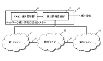
- the present invention can be realized by a network statistical information providing system including a domain boundary management unit 11 and a statistical information conversion unit 12, as shown in FIG.
- the domain boundary management unit 11 includes a first domain 31 configured to include a device capable of acquiring statistical information having a predetermined granularity, and a second domain not including a device capable of acquiring statistical information having the predetermined granularity.
- the link information between the domain 32 is managed.
- the “domain” refers to a set of switches that can be reached in a network and whose statistical information can be acquired with the same type and granularity among a group of switches managed by one or more control devices.
- the “domain boundary” is a boundary point between two domains, and is expressed by link information such as a connection between a switch port of the first domain 31 and a switch port of the second domain 32.
- the statistical information conversion unit 12 uses the link information acquired from the domain boundary management unit 11 to convert the statistical information acquired from the first domain 31 into statistical information that does not belong to a domain boundary, statistical information that belongs to a domain boundary, The statistical information belonging to the domain boundary is subjected to predetermined processing and provided as statistical information across a plurality of domains.
- the statistical information conversion unit 12 converts the station statistical information acquired from the first domain 31 into the first domain 31 and the second domain.
- the statistical information of the stations that do not belong to the domain boundary b1 between 32 and the statistical information of the stations that belong to the domain boundary b1 are classified.
- the statistical information conversion unit 12 processes the statistical information of the stations belonging to the domain boundary b1, converts the statistical information between the stations belonging to the domain boundary b1 of the first domain 31 and the statistical information between the second domains 32, and presents it (See FIG. 13).
- the first domain 31 and the third domain 33 capable of acquiring statistical information having a predetermined granularity are connected via the second domain 32, and the statistical information conversion unit 12 is connected to the first domain 31.
- the statistical information conversion unit 12 presents information of one domain as related information with another domain by combining these statistical information.
- the station statistical information conversion unit 12 determines that the first domain 31 The number of packets transmitted / received to / from the third domain 33 can be obtained from the number of transmitted / received packets of the station statistical information.
- the difference between the number of transmitted / received packets between the second domain 32 and the third domain 33 is obtained from the number of transmitted / received packets between the first domain 31 and the second domain 32, the difference between the first domain 31 and the second domain 32 is obtained. It is also possible to determine the number of transmitted / received packets.
- the statistical information obtained as described above is a useful clue for tracking transmission / reception packets of a station in the first domain, and can be used for failure analysis.
- FIG. 3 is a diagram illustrating a system configuration according to the first embodiment of this invention.
- the OpenFlow controller 200 that controls the OpenFlow domain A and the OpenFlow domain C
- the Legacy controller 201 that manages the Legacy domain B and the Legacy domain D
- the integrated controller 100 that controls the OpenFlow controller 200 and the Legacy controller 201.
- a configuration in which is connected is shown.
- the OpenFlow controller 200 and OpenFlow domain A and OpenFlow domain C, and the Legacy controller 201 and Legacy domain B and Legacy domain D are connected by control channels 500 to 503, respectively.
- the control channels 500 to 503 are represented by a single line, but actually, the control channels 500 to 503 include the switches included in each domain, the OpenFlow controller 200, and the Legacy controller 201. Are connected.
- the OpenFlow domain A and the Legacy domain B are connected at the domain boundary b1.
- Legacy domain B and OpenFlow domain C are connected at domain boundary b2
- OpenFlow domain C and Legacy domain D are connected at domain boundary b3.
- the integrated controller 100 includes a domain management unit 110, a domain boundary management unit 111, and a statistical information conversion unit 150.
- the domain management unit 110 manages domain information such as a controller that controls each domain and what statistical information can be acquired.
- FIG. 4 is an example of a domain information management table held in the domain management unit 110.
- the domains A and C are controlled by the OpenFlow controller 200, and in addition to port statistics, Station statistics and data flow statistics can be acquired (Supported).
- the domains B and D are managed by the Legacy controller 201, and only port statistics can be acquired, and Station statistics and data flow statistics cannot be acquired (Not supported).
- the domain boundary management unit 111 manages link information that is a boundary point between two domains.
- FIG. 5 is an example of a domain boundary information management table held in the domain boundary management unit 111.
- a table is shown in which domain IDs at both ends of each domain boundary, switch IDs, and port IDs are managed in association with each other.
- the domain boundary b1 is configured by a link between the port # p3 of the switch (sw3) of the domain A and the port # p3 of the switch (sw1) of the domain B. .
- data set in the domain management unit 110 and the domain boundary management unit 111 may be input in advance by the user.
- the integrated controller 100, the OpenFlow controller 200, or the Legacy controller 201 may automatically register based on information acquired from domains controlled or managed, respectively.
- the statistical information conversion unit 150 performs predetermined processing on statistical information having a different granularity for each domain, converts the statistical information into statistical information across multiple domains, and outputs the statistical information to the management terminal 600.
- the operation of the statistical information conversion unit 150 will be described in detail later using a specific example.
- the OpenFlow controller 200 is a control device that controls switches (OpenFlow switches) arranged in the domains A and C based on the control policy set by the integrated controller 100 (see Non-Patent Documents 1 and 2). Further, the OpenFlow controller 200 provides station statistical information to the integrated controller 100.
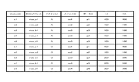
- FIG. 6 is a diagram illustrating an example of station statistical information provided to the integrated controller 100 by the OpenFlow controller 200 of the present embodiment. As shown in FIG. 6, the station statistical information is configured by associating the number of transmitted packets (TX) with the number of received packets (RX) for each MAC address of a terminal connected to a switch port belonging to a domain. ing.
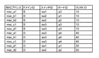
- FIG. 7 is a diagram illustrating an example of the MAC address table information provided to the integrated controller 100 by the Legacy controller 201 of the present embodiment.
- a MAC address table obtained by merging the MAC address table of the domain B edge switch and the MAC address table of the domain D edge switch is shown. For example, when the edge switch sw1 of the domain B receives a packet whose MAC address is mac_a1, the edge switch sw1 performs an operation of outputting from the port # p3.
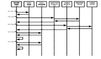
- FIG. 8 is a sequence diagram showing the operation of the first exemplary embodiment of the present invention.
- FIG. 9 is a flowchart showing the operation of the statistical information conversion unit 150 of FIG.
- the statistical information conversion unit 150 of the integrated controller 100 searches the management table from the domain management unit 110 and acquires information on the domain to be controlled (step S1 in FIGS. 8 and 9).
- the statistical information conversion unit 150 acquires station statistical information from the OpenFlow controller 200 for each of the domains A and C from which Station statistical information can be acquired (step S2 in FIGS. 8 and 9).
- the statistical information conversion unit 150 has acquired the station statistical information illustrated in FIG. 6 by making an inquiry to the OpenFlow switch under control of the OpenFlow controller 200.
- the statistical information conversion unit 150 acquires the MAC address table information of the edge switches in each domain from the Legacy controller 201 for each of the domains B and D for which Station statistical information cannot be acquired (FIG. 8, Step S3 in FIG.
- the statistical information conversion unit 150 has acquired the MAC address table information illustrated in FIG. 7 by making an inquiry to the Legacy switch under management by the Legacy controller 201.
- the statistical information conversion unit 150 classifies the Station statistical information entries of FIG. 6 into Station entries (1) that do not belong to the domain boundary and Station entries (2) that belong to the domain boundary. Whether a station belongs to a domain boundary can be determined based on whether each station is connected to the domain boundary shown in FIG.
- FIG. 10 is a diagram showing a state where symbols (1) and (2) indicating whether or not belonging to a domain boundary are attached based on the station statistical information of FIG.
- the statistical information conversion unit 150 extracts the stations of the domains B and D by extracting the MAC address belonging to the terminal side port from the MAC learning table of FIG. Whether or not the MAC address belongs to the terminal-side port can be acquired from the Legacy controller 201 that manages the domains B and D.
- FIG. 11 is a diagram illustrating a state in which the symbol (3) is added to the entry having the MAC address belonging to the terminal-side port among the entries in the MAC learning table of FIG.
- the statistical information conversion unit 150 takes the union of the entry with the symbol (1) in FIG. 10 and the entry with the symbol (3) in FIG. 11 to obtain an integrated station statistical table for the integrated controller. (Corresponding to the first table) is created (step S4 in FIGS. 8 and 9).
- FIG. 12 is an example of an integrated station statistics table for the integrated controller generated in step S4. In the example of FIG. 12, Station IDs that have been renumbered are assigned to all Stations. For the entry determined to be a MAC address belonging to the terminal side port from the MAC learning table of FIG. 7, N / A is set because the TX and RX values are not originally obtained.
- the statistical information conversion unit 150 processes the station statistical information at the domain boundary marked with the symbol (2) in FIG.
- the statistical information conversion unit 150 extracts an entry having the same MAC address as that of the station with the symbol (2) determined to be on the domain boundary in FIG. 10 from the entries in the integrated station statistical table of FIG. .
- the same entry as the MAC address is taken out from the entry with the symbol (2) in FIG. 10 and collected in a table (corresponding to the second table) indicating the number of transmitted / received packets from one station to another domain. (Step S5 in FIGS. 8 and 9).
- FIG. 13 is a diagram for explaining the processing of the station statistical information at the domain boundary marked with the symbol (2) in FIG. 10 by the statistical information conversion unit 150.
- the upper table of FIG. 13 is the integrated station statistics table of FIG.
- the station with the top MAC address mac_a1 in the upper table of FIG. 13 belongs to the boundary of the third domain C from the bottom of FIG. 10, and is the same MAC as the station connected to the port # p3 of the switch sw3. Have an address. This indicates that the packet transmitted / received from the station having the MAC address mac_a1 reaches the switch of the domain C via the domain B and appears in the station statistics. Therefore, the statistical information conversion unit 150 extracts the corresponding entry (third from the bottom) in FIG. 10, and generates an entry in which the opposite domain is domain C, TX is 200, and RX is 200, as shown in the lower part of FIG. To do.
- the station with the second MAC address mac_a2 from the upper table in FIG. 13 does not appear as a station on the domain boundary marked with the symbol (2) in FIG. This indicates that the packet transmitted / received from the station having the MAC address mac_a2 does not reach the switch of the domain C via the domain B. Therefore, the statistical information conversion unit 150 does not create an entry for the station whose MAC address is mac_a2.
- the station with the third MAC address mac_b1 in the upper table in FIG. 13 belongs to the boundary of the third domain A from the top in FIG. 10, and is the same as the station connected to the port # p3 of the switch sw3.
- the station with the MAC address mac_b1 belongs to the boundary of the second domain C from the bottom in FIG. 10, and has the same MAC address as the station connected to the port # p3 of the switch sw3. This indicates that packets transmitted / received from the station with the MAC address mac_b1 reach the switches of the domain A and the domain C and appear in the station statistics. Therefore, the statistical information conversion unit 150 takes out the corresponding entry (third from the top and second from the bottom) in FIG. 10, and as shown in the lower part of FIG. 100 entries and an entry in which the opposite domain is domain C, TX is 200, and RX is 200 are generated.
- the number of transmission / reception packets of the station having the MAC address mac_a1 of the domain A is 400, and of these, the number of packets transmitted / received to / from the domain C is 200 each. Information can be provided.
- the data flow statistics are an end-to-end flow (hereinafter referred to as “data flow”) from one station (having “MAC address 1”) to another station (having “MAC address 2”). And statistical information indicating the number of packets transmitted in the flow.
- the statistical information conversion unit 150 of the integrated controller 100 in FIG. 3 first acquires the data flow statistics acquired from the domains A and C via the OpenFlow controller 200, and performs the following processing for each data flow.
- the statistical information conversion unit 150 identifies the domain to which each of the transmission source station and the transmission destination station of each data flow belongs. For example, the contents that the transmission source station belongs to the domain A in FIG. 3 and the transmission destination station belongs to the domain D are specified. This processing can be realized by specifying the domain to which the MAC address shown in the data flow statistics acquired from the domains A and C belongs, as in steps S1 to S3 of the first embodiment.
- the statistical information conversion unit 150 searches for stations belonging to the domain boundary based on the transmission source and transmission destination stations specified in (2-1) above.
- the station belonging to the domain boundary here is station statistical information related to the port of the switch registered in the domain boundary management unit 111, and is included in the MAC address table of the Legacy domain as well as the station of the OpenFlow domain.
- the registered MAC address is also included.
- the statistical information conversion unit 150 identifies a switch and a port in the domain through which the data flow passes for each passing domain.
- the transit domain is the OpenFlow domain
- the transit domain is the Legacy domain
- the MAC address table of the switch in the domain can be searched using the MAC address of the transmission destination station as a key, and can be specified by tracing the switch and port that pass through. In any case, if information cannot be obtained on the way, the statistical information conversion unit 150 presents N / A as information on switches and ports that pass through in the domain thereafter.
- the data flow statistics are converted into statistical information on the number of transmitted packets for each domain including the domain through which the data flow specified in (2-2) passes, and presented.
- the statistical information conversion unit 150 presents the number of transmitted packets of data flow statistics for each domain.
- the passing domain is the OpenFlow domain
- the number of transmission packets (TX) obtained from the acquired data flow statistics is presented, and in the case of the Legacy domain, N / A may be presented.
- the data flow statistics can be developed as information of the entire network managed by the integrated controller 100 as shown in FIG.
- Port statistics are statistical information on the number of packets sent and received by the port. This port statistic is statistical information that can be acquired even by the Legacy switch. However, the statistical information conversion unit 150 of the integrated controller 100 of this embodiment uses the station statistic to transmit / receive the number of transmission / reception packets in the domain and transmission / reception between domains. Present the number of packets.
- the statistical information conversion unit 150 first acquires the port statistics of the switches belonging to the domains B and D, which are Legacy domains, via the Legacy controller 201 of FIG.
- the statistical information conversion unit 150 identifies the station connected to the port and obtains the MAC address of each station.
- the statistical information conversion unit 150 searches the station statistics belonging to the domain boundary of the domain reachable from the domain to which the port from which the port statistics are acquired belongs, using the acquired MAC address of the station as a key. For example, when the switch that acquired the port statistics belongs to the domain B, the station statistics that belong to the domain boundary of the domains that can be reached from the domain B (for example, the domains A and C) are searched.
- the domain C that can be reached from the domain B and the domain D that can be reached from the domain C are sequentially traced, and the station whose MAC address matches each domain boundary. Get statistics.
- the statistical information conversion unit 150 calculates the difference from the acquired station statistics, and out of the number of transmitted / received packets of the port from which the port statistics are acquired, The number of packets processed in the domain can be presented.
- the MAC address is used as the statistical information acquisition unit.
- the domain information, the switch ID, the port ID, the VLAN ID, and the like can be combined to obtain the key information.
- Non-Patent Documents 1 and 2 in order to specify a flow, information corresponding to a match condition of a flow entry set in each OpenFlow switch can be used as key information.
- the statistical information that can be acquired from the first domain includes station statistical information indicating the traffic for each MAC address observed by the switch belonging to the first domain,
- the statistical information conversion unit A first table storing station statistical information that does not belong to the domain boundary, and station information identified from a MAC address table of an edge switch of the second domain;
- a system for providing network statistical information which generates a second table in which an entry having the same MAC address as a station appearing in the first table is extracted from the station statistical information belonging to the classified domain boundary.
- the statistical information that can be acquired from the first domain includes flow statistical information indicating a path between two MAC addresses observed by a switch and a traffic amount
- the statistical information conversion unit is a system for providing network statistical information that generates statistical information for each domain on a path between the two MAC addresses based on the flow statistical information.
- the statistical information conversion unit The path between two MAC addresses is specified using the packet transfer control information set in the first domain switch and the MAC address table set in the second domain switch. Network statistics information providing system.
- the statistical information conversion unit As the statistical information, Obtaining port statistics obtained from the second domain, obtaining station statistics of the MAC address from which the port statistics were obtained from the first domain, A system for providing network statistical information that provides both the port statistics and the station statistics.
- Providing network statistical information including a first controller that manages the first domain, a second controller that manages the second domain, and an integrated controller that controls the first and second controllers system.
- the first domain is configured by a group of switches controlled by a central control network control device, The system for providing network statistical information, wherein the second domain includes a group of switches that are not controlled by the control device.
- the eighth and ninth embodiments can be developed into the second to seventh embodiments as in the first embodiment.
Landscapes
- Engineering & Computer Science (AREA)
- Computer Networks & Wireless Communication (AREA)
- Signal Processing (AREA)
- Physics & Mathematics (AREA)
- Algebra (AREA)
- General Physics & Mathematics (AREA)
- Mathematical Analysis (AREA)
- Mathematical Optimization (AREA)
- Mathematical Physics (AREA)
- Probability & Statistics with Applications (AREA)
- Pure & Applied Mathematics (AREA)
- Data Exchanges In Wide-Area Networks (AREA)
Abstract
Description
本発明は、日本国特許出願:特願2013-060710号(2013年 3月22日出願)に基づくものであり、同出願の全記載内容は引用をもって本書に組み込み記載されているものとする。
本発明は、ネットワーク統計情報の提供システム、ネットワーク統計情報の提供方法及びプログラムに関し、特に、異なる種類のネットワークから得られたネットワーク統計情報の提供システム、ネットワーク統計情報の提供方法及びプログラムに関する。
続いて、本発明の第1の実施形態について図面を参照して詳細に説明する。図3は、本発明の第1の実施形態のシステム構成を示す図である。図3を参照すると、OpenFlowドメインA及びOpenFlowドメインCを制御するOpenFlowコントローラ200と、LegacyドメインB及びLegacyドメインDを管理するLegacyコントローラ201と、OpenFlowコントローラ200及びLegacyコントローラ201を制御する統合コントローラ100とを接続した構成が示されている。
続いて、上記第1の実施形態と同様の構成にて、データフロー統計の変換を行うようにした第2の実施形態について説明する。基本的な構成は、第1の実施形態と同様であるので、以下、その相違点を中心に説明する。
続いて、上記第1の実施形態と同様の構成にて、ポート統計の変換を行うようにした第3の実施形態について説明する。基本的な構成は、第1の実施形態と同様であるので、以下、その相違点を中心に説明する。
[第1の形態]
(上記第1の視点によるネットワーク統計情報の提供システム参照)
[第2の形態]
第1の形態のネットワーク統計情報の提供システムにおいて、
前記第1のドメインから取得可能な統計情報には、前記第1のドメインに属するスイッチが観測したMACアドレス毎の通信量を示すステーション統計情報が含まれ、
前記統計情報変換部は、
前記ドメイン境界に属さないステーション統計情報と、前記第2のドメインのエッジスイッチのMACアドレステーブルから特定したステーションの情報とを格納した第1のテーブルと、
前記分類したドメイン境界に属するステーション統計情報のうち、前記第1のテーブルに表れたステーションと同一のMACアドレスを持つエントリを抽出した第2のテーブルとを生成するネットワーク統計情報の提供システム。
[第3の形態]
第1又は第2の形態のネットワーク統計情報の提供システムにおいて、
前記第1のドメインから取得可能な統計情報には、あるスイッチが観測した2つのMACアドレス間の経路と通信量を示すフロー統計情報が含まれ、
前記統計情報変換部は、前記フロー統計情報に基づいて、前記2つのMACアドレス間の経路上のドメイン毎の統計情報を生成するネットワーク統計情報の提供システム。
[第4の形態]
第3の形態のネットワーク統計情報の提供システムにおいて、
前記統計情報変換部は、
前記第1のドメインのスイッチに設定されているパケット転送用の制御情報と、前記第2のドメインのスイッチに設定されているMACアドレステーブルとを用いて、2つのMACアドレス間の経路を特定するネットワーク統計情報の提供システム。
[第5の形態]
第1~第4いずれか一の形態のネットワーク統計情報の提供システムにおいて、
前記統計情報変換部は、
前記統計情報として、
前記第2のドメインから取得したポート統計を取得し、前記第1のドメインから前記ポート統計を取得したMACアドレスのステーション統計を取得し、
前記ポート統計と、前記ステーション統計とを併せて提供するネットワーク統計情報の提供システム。
[第6の形態]
第1~第5いずれか一の形態のネットワーク統計情報の提供システムにおいて、
前記第1のドメインを管理する第1のコントローラと、前記第2のドメインを管理する第2のコントローラと、前記第1、第2のコントローラとを制御する統合コントローラとを含むネットワーク統計情報の提供システム。
[第7の形態]
第1~第6いずれか一の形態のネットワーク統計情報の提供システムにおいて、
前記第1のドメインは、集中制御型のネットワークの制御装置によって制御されるスイッチ群によって構成され、
前記第2のドメインは、前記制御装置の制御を受けないスイッチ群によって構成されているネットワーク統計情報の提供システム。
[第8の形態]
(上記第2の視点によるネットワーク統計情報の提供方法参照)
[第9の形態]
(上記第3の視点によるプログラム参照)
なお、上記第8、第9の形態は、第1の形態と同様に、第2~第7の形態に展開することが可能である。
11、111 ドメイン境界管理部
12、150 統計情報変換部
31 第1ドメイン
32 第2ドメイン
33 第3ドメイン
100 統合コントローラ
110 ドメイン管理部
200 OpenFlowコントローラ
201 Legacyコントローラ
300~303 ドメイン
500~503 制御用チャネル
600 管理端末
b1~b3 ドメイン境界
Claims (17)
- 所定の粒度を持つ統計情報を取得可能な機器を含んで構成される第1のドメインと、前記所定の粒度を持つ統計情報を取得可能な機器が含まれない第2のドメインと、の間のリンク情報を管理するドメイン境界管理部と、
前記リンク情報を用いて、前記第1のドメインから取得した統計情報を、ドメイン境界に属さない統計情報と、ドメイン境界に属する統計情報とに分類し、
前記ドメイン境界に属する統計情報に所定の加工を施して、複数のドメインを跨る統計情報として提供する統計情報変換部と、
を含むネットワーク統計情報の提供システム。 - 前記第1のドメインから取得可能な統計情報には、前記第1のドメインに属するスイッチが観測したMACアドレス毎の通信量を示すステーション統計情報が含まれ、
前記統計情報変換部は、
前記ドメイン境界に属さないステーション統計情報と、前記第2のドメインのエッジスイッチのMACアドレステーブルから特定したステーションの情報とを格納した第1のテーブルと、
前記分類したドメイン境界に属するステーション統計情報のうち、前記第1のテーブルに表れたステーションと同一のMACアドレスを持つエントリを抽出した第2のテーブルとを生成する請求項1のネットワーク統計情報の提供システム。 - 前記第1のドメインから取得可能な統計情報には、あるスイッチが観測した2つのMACアドレス間の経路と通信量を示すフロー統計情報が含まれ、
前記統計情報変換部は、前記フロー統計情報に基づいて、前記2つのMACアドレス間の経路上のドメイン毎の統計情報を生成する請求項1又は2のネットワーク統計情報の提供システム。 - 前記統計情報変換部は、
前記第1のドメインのスイッチに設定されているパケット転送用の制御情報と、前記第2のドメインのスイッチに設定されているMACアドレステーブルとを用いて、2つのMACアドレス間の経路を特定する請求項3のネットワーク統計情報の提供システム。 - 前記統計情報変換部は、
前記統計情報として、
前記第2のドメインから取得したポート統計を取得し、前記第1のドメインから前記ポート統計を取得したMACアドレスのステーション統計を取得し、
前記ポート統計と、前記ステーション統計とを併せて提供する請求項1から4いずれか一のネットワーク統計情報の提供システム。 - 前記第1のドメインを管理する第1のコントローラと、前記第2のドメインを管理する第2のコントローラと、前記第1、第2のコントローラとを制御する統合コントローラとを含む請求項1から5いずれか一のネットワーク統計情報の提供システム。
- 前記第1のドメインは、集中制御型のネットワークの制御装置によって制御されるスイッチ群によって構成され、
前記第2のドメインは、前記制御装置の制御を受けないスイッチ群によって構成されている請求項1から6いずれか一のネットワーク統計情報の提供システム。 - 所定の粒度を持つ統計情報を取得可能な機器を含んで構成される第1のドメインと、前記所定の粒度を持つ統計情報を取得可能な機器が含まれない第2のドメインと、の間のリンク情報を管理するドメイン境界管理部を備えるコンピュータが、
前記リンク情報を用いて、前記第1のドメインから取得した統計情報を、ドメイン境界に属さない統計情報と、ドメイン境界に属する統計情報とに分類するステップと、
前記ドメイン境界に属する統計情報に所定の加工を施して、複数のドメインを跨る統計情報として提供するステップと、
を含むネットワーク統計情報の提供方法。 - 前記第1のドメインから取得可能な統計情報には、前記第1のドメインに属するスイッチが観測したMACアドレス毎の通信量を示すステーション統計情報が含まれ、
前記コンピュータが、
前記ドメイン境界に属さないステーション統計情報と、前記第2のドメインのエッジスイッチのMACアドレステーブルから特定したステーションの情報とを格納した第1のテーブルと、
前記分類したドメイン境界に属するステーション統計情報のうち、前記第1のテーブルに表れたステーションと同一のMACアドレスを持つエントリを抽出した第2のテーブルとを生成するステップを含む、請求項8のネットワーク統計情報の提供方法。 - 前記第1のドメインから取得可能な統計情報には、あるスイッチが観測した2つのMACアドレス間の経路と通信量を示すフロー統計情報が含まれ、
前記コンピュータが、前記フロー統計情報に基づいて、前記2つのMACアドレス間の経路上のドメイン毎の統計情報を生成するステップを含む、請求項8又は9のネットワーク統計情報の提供方法。 - 前記コンピュータが、
前記第1のドメインのスイッチに設定されているパケット転送用の制御情報と、前記第2のドメインのスイッチに設定されているMACアドレステーブルとを用いて、2つのMACアドレス間の経路を特定するステップを含む、請求項10のネットワーク統計情報の提供方法。 - 前記コンピュータが、
前記統計情報として、前記第2のドメインから取得したポート統計を取得し、前記第1のドメインから前記ポート統計を取得したMACアドレスのステーション統計を取得するステップと、
前記ポート統計と、前記ステーション統計とを併せて提供するステップと、を含む、請求項8から11いずれか一のネットワーク統計情報の提供方法。 - 所定の粒度を持つ統計情報を取得可能な機器を含んで構成される第1のドメインと、前記所定の粒度を持つ統計情報を取得可能な機器が含まれない第2のドメインと、の間のリンク情報を管理するドメイン境界管理部を備えるコンピュータに、
前記リンク情報を用いて、前記第1のドメインから取得した統計情報を、ドメイン境界に属さない統計情報と、ドメイン境界に属する統計情報とに分類する処理と、
前記ドメイン境界に属する統計情報に所定の加工を施して、複数のドメインを跨る統計情報として提供する処理と、
を実行させるプログラム。 - 前記第1のドメインから取得可能な統計情報には、前記第1のドメインに属するスイッチが観測したMACアドレス毎の通信量を示すステーション統計情報が含まれ、
前記ドメイン境界に属さないステーション統計情報と、前記第2のドメインのエッジスイッチのMACアドレステーブルから特定したステーションの情報とを格納した第1のテーブルと、
前記分類したドメイン境界に属するステーション統計情報のうち、前記第1のテーブルに表れたステーションと同一のMACアドレスを持つエントリを抽出した第2のテーブルとを生成する処理を前記コンピュータに実行させる、請求項13のプログラム。 - 前記第1のドメインから取得可能な統計情報には、あるスイッチが観測した2つのMACアドレス間の経路と通信量を示すフロー統計情報が含まれ、
前記フロー統計情報に基づいて、前記2つのMACアドレス間の経路上のドメイン毎の統計情報を生成する処理を前記コンピュータに実行させる、請求項13又は14のプログラム。 - 前記第1のドメインのスイッチに設定されているパケット転送用の制御情報と、前記第2のドメインのスイッチに設定されているMACアドレステーブルとを用いて、2つのMACアドレス間の経路を特定する処理を前記コンピュータに実行させる、請求項15のプログラム。
- 前記統計情報として、前記第2のドメインから取得したポート統計を取得し、前記第1のドメインから前記ポート統計を取得したMACアドレスのステーション統計を取得する処理と、
前記ポート統計と、前記ステーション統計とを併せて提供する処理と、を前記コンピュータに実行させる、請求項13から16いずれか一のプログラム。
Priority Applications (4)
| Application Number | Priority Date | Filing Date | Title |
|---|---|---|---|
| JP2015506857A JP5971405B2 (ja) | 2013-03-22 | 2014-03-20 | ネットワーク統計情報の提供システム、ネットワーク統計情報の提供方法及びプログラム |
| US14/777,898 US20160294634A1 (en) | 2013-03-22 | 2014-03-20 | Network statistical information providing system, network statistical information providing method, and program |
| CN201480017398.8A CN105052088A (zh) | 2013-03-22 | 2014-03-20 | 网络统计信息提供系统、网络统计信息提供方法和程序 |
| EP14768352.8A EP2978172A4 (en) | 2013-03-22 | 2014-03-20 | SYSTEM FOR PROVIDING NETWORK STATISTICS INFORMATION, METHOD FOR PROVIDING NETWORK STATISTICS INFORMATION AND PROGRAM |
Applications Claiming Priority (2)
| Application Number | Priority Date | Filing Date | Title |
|---|---|---|---|
| JP2013060710 | 2013-03-22 | ||
| JP2013-060710 | 2013-03-22 |
Publications (1)
| Publication Number | Publication Date |
|---|---|
| WO2014148613A1 true WO2014148613A1 (ja) | 2014-09-25 |
Family
ID=51580283
Family Applications (1)
| Application Number | Title | Priority Date | Filing Date |
|---|---|---|---|
| PCT/JP2014/057826 Ceased WO2014148613A1 (ja) | 2013-03-22 | 2014-03-20 | ネットワーク統計情報の提供システム、ネットワーク統計情報の提供方法及びプログラム |
Country Status (5)
| Country | Link |
|---|---|
| US (1) | US20160294634A1 (ja) |
| EP (1) | EP2978172A4 (ja) |
| JP (1) | JP5971405B2 (ja) |
| CN (1) | CN105052088A (ja) |
| WO (1) | WO2014148613A1 (ja) |
Cited By (1)
| Publication number | Priority date | Publication date | Assignee | Title |
|---|---|---|---|---|
| JP2018500830A (ja) * | 2014-12-22 | 2018-01-11 | ホアウェイ・テクノロジーズ・カンパニー・リミテッド | 攻撃データパケット処理のための方法、装置、及びシステム |
Families Citing this family (2)
| Publication number | Priority date | Publication date | Assignee | Title |
|---|---|---|---|---|
| EP3105697A4 (en) * | 2014-02-16 | 2017-12-13 | B.G. Negev Technologies & Applications Ltd. at Ben-Gurion University | A system and method for integrating legacy flow-monitoring systems with sdn networks |
| WO2018195877A1 (zh) * | 2017-04-27 | 2018-11-01 | 华为技术有限公司 | 通信方法、装置和系统 |
Citations (4)
| Publication number | Priority date | Publication date | Assignee | Title |
|---|---|---|---|---|
| JP2010124512A (ja) | 2010-03-11 | 2010-06-03 | Cloud Scope Technologies Inc | ネットワーク情報提示装置及び方法 |
| JP2011166661A (ja) * | 2010-02-15 | 2011-08-25 | Nec Corp | 帯域制御システム、帯域制御装置、帯域制御方法および帯域制御プログラム |
| JP2012074867A (ja) | 2010-09-28 | 2012-04-12 | Oki Electric Ind Co Ltd | トラフィック監視システム、トラフィック監視方法及び網管理システム |
| WO2012098786A1 (ja) * | 2011-01-17 | 2012-07-26 | 日本電気株式会社 | ネットワークシステム、コントローラ、スイッチ、及びトラフィック監視方法 |
Family Cites Families (8)
| Publication number | Priority date | Publication date | Assignee | Title |
|---|---|---|---|---|
| JP4530707B2 (ja) * | 2004-04-16 | 2010-08-25 | 株式会社クラウド・スコープ・テクノロジーズ | ネットワーク情報提示装置及び方法 |
| DE102006015239B3 (de) * | 2006-03-30 | 2007-08-23 | Siemens Ag | Netzzugangssteuerung mit zusätzlicher Verkehrsklasse in einem Kommunikationsnetz |
| US7924715B2 (en) * | 2008-05-12 | 2011-04-12 | Nortel Networks Limited | Method and apparatus for discovering, negotiating, and provisioning end-to-end SLAs between multiple service provider domains |
| CN101753366B (zh) * | 2008-12-01 | 2013-04-17 | 华为技术有限公司 | 一种实现虚拟私有网流量统计的方法、设备和系统 |
| US8484704B2 (en) * | 2009-09-16 | 2013-07-09 | Avaya Inc. | Next generation integration between different domains, such as, enterprise and service provider using sequencing applications and IMS peering |
| US8705542B2 (en) * | 2010-06-17 | 2014-04-22 | Telfonaktiebolaget Lm Ericsson (Publ) | L2 method for partial VLAN service migration |
| JP5850471B2 (ja) * | 2010-08-20 | 2016-02-03 | 日本電気株式会社 | 通信システム、制御装置、ノード制御方法およびプログラム |
| US9432215B2 (en) * | 2013-05-21 | 2016-08-30 | Nicira, Inc. | Hierarchical network managers |
-
2014
- 2014-03-20 EP EP14768352.8A patent/EP2978172A4/en not_active Withdrawn
- 2014-03-20 JP JP2015506857A patent/JP5971405B2/ja not_active Expired - Fee Related
- 2014-03-20 CN CN201480017398.8A patent/CN105052088A/zh active Pending
- 2014-03-20 WO PCT/JP2014/057826 patent/WO2014148613A1/ja not_active Ceased
- 2014-03-20 US US14/777,898 patent/US20160294634A1/en not_active Abandoned
Patent Citations (4)
| Publication number | Priority date | Publication date | Assignee | Title |
|---|---|---|---|---|
| JP2011166661A (ja) * | 2010-02-15 | 2011-08-25 | Nec Corp | 帯域制御システム、帯域制御装置、帯域制御方法および帯域制御プログラム |
| JP2010124512A (ja) | 2010-03-11 | 2010-06-03 | Cloud Scope Technologies Inc | ネットワーク情報提示装置及び方法 |
| JP2012074867A (ja) | 2010-09-28 | 2012-04-12 | Oki Electric Ind Co Ltd | トラフィック監視システム、トラフィック監視方法及び網管理システム |
| WO2012098786A1 (ja) * | 2011-01-17 | 2012-07-26 | 日本電気株式会社 | ネットワークシステム、コントローラ、スイッチ、及びトラフィック監視方法 |
Non-Patent Citations (3)
| Title |
|---|
| NICK MCKEOWN ET AL., OPENFLOW: ENABLING INNOVATION IN CAMPUS NETWORKS, 9 January 2013 (2013-01-09), Retrieved from the Internet <URL:http://www.openflow.org/documents/openflow-wp-latest.pdf> |
| OPENFLOW SWITCH SPECIFICATION'' VERSION 1.3.1. (WIRE PROTOCOL 0X04, 9 January 2013 (2013-01-09), Retrieved from the Internet <URL:http://www.opennetworking.org/images/stories/downloads/specif ication/openflow-spec-vl.3.1 pdf> |
| See also references of EP2978172A4 |
Cited By (2)
| Publication number | Priority date | Publication date | Assignee | Title |
|---|---|---|---|---|
| JP2018500830A (ja) * | 2014-12-22 | 2018-01-11 | ホアウェイ・テクノロジーズ・カンパニー・リミテッド | 攻撃データパケット処理のための方法、装置、及びシステム |
| US10742682B2 (en) | 2014-12-22 | 2020-08-11 | Huawei Technologies Co., Ltd. | Attack data packet processing method, apparatus, and system |
Also Published As
| Publication number | Publication date |
|---|---|
| EP2978172A4 (en) | 2016-11-09 |
| CN105052088A (zh) | 2015-11-11 |
| JP5971405B2 (ja) | 2016-08-17 |
| US20160294634A1 (en) | 2016-10-06 |
| JPWO2014148613A1 (ja) | 2017-02-16 |
| EP2978172A1 (en) | 2016-01-27 |
Similar Documents
| Publication | Publication Date | Title |
|---|---|---|
| CN103379039B (zh) | 一种用于流统计的方法、装置及系统 | |
| JP5742834B2 (ja) | 通信システム、経路制御装置、パケット転送装置および経路制御方法 | |
| US9584568B2 (en) | Signal processing apparatus and signal processing method thereof for implementing a broadcast or a multicast communication | |
| US20160301603A1 (en) | Integrated routing method based on software-defined network and system thereof | |
| US20130177016A1 (en) | Communication system, control apparatus, packet handling operation setting method, and program | |
| US10069648B2 (en) | Communication system, control apparatus, communication control method and program | |
| US9674080B2 (en) | Proxy for port to service instance mapping | |
| US20140010235A1 (en) | Network system and switching method thereof | |
| KR20130125826A (ko) | 네트워크 시스템 및 vlan 태그 정보 취득 방법 | |
| US20200304399A1 (en) | Method and system for interfacing communication networks | |
| CN104509045A (zh) | 控制装置、通信系统、通信方法和程序 | |
| JP5725236B2 (ja) | 通信システム、ノード、パケット転送方法およびプログラム | |
| US9832114B2 (en) | Packet forwarding system, control apparatus, packet forwarding method, and program | |
| JP5971405B2 (ja) | ネットワーク統計情報の提供システム、ネットワーク統計情報の提供方法及びプログラム | |
| US20180083873A1 (en) | Communication system, control apparatus, control method and program | |
| CN105553876B (zh) | 报文处理的方法及网络节点 | |
| US10516604B2 (en) | Packet forwarding system, control apparatus, and control method and program for relay device | |
| US10044671B2 (en) | Control apparatus, communication system, communication method, and program | |
| JP2017050708A (ja) | 通信システム、制御装置、スイッチ、通信方法及びプログラム | |
| WO2015045275A1 (ja) | 制御装置、ネットワークシステム、パケット転送制御方法、制御装置用プログラム | |
| JP2012151689A (ja) | トラヒック情報収集装置、ネットワーク制御装置およびトラヒック情報収集方法 | |
| US11356377B2 (en) | Distribution method for a connection with multiple and heterogenous links | |
| EP3217615A1 (en) | Control device, communication system, and relay device control method |
Legal Events
| Date | Code | Title | Description |
|---|---|---|---|
| WWE | Wipo information: entry into national phase |
Ref document number: 201480017398.8 Country of ref document: CN |
|
| 121 | Ep: the epo has been informed by wipo that ep was designated in this application |
Ref document number: 14768352 Country of ref document: EP Kind code of ref document: A1 |
|
| WWE | Wipo information: entry into national phase |
Ref document number: 14777898 Country of ref document: US |
|
| ENP | Entry into the national phase |
Ref document number: 2015506857 Country of ref document: JP Kind code of ref document: A |
|
| REEP | Request for entry into the european phase |
Ref document number: 2014768352 Country of ref document: EP |
|
| WWE | Wipo information: entry into national phase |
Ref document number: 2014768352 Country of ref document: EP |
|
| NENP | Non-entry into the national phase |
Ref country code: DE |