WO2014155496A1 - リチウムイオン電池、およびリチウムイオン電池用電極 - Google Patents
リチウムイオン電池、およびリチウムイオン電池用電極 Download PDFInfo
- Publication number
- WO2014155496A1 WO2014155496A1 PCT/JP2013/058608 JP2013058608W WO2014155496A1 WO 2014155496 A1 WO2014155496 A1 WO 2014155496A1 JP 2013058608 W JP2013058608 W JP 2013058608W WO 2014155496 A1 WO2014155496 A1 WO 2014155496A1
- Authority
- WO
- WIPO (PCT)
- Prior art keywords
- mixture layer
- negative
- heat generation
- lithium
- positive electrode
- Prior art date
- Legal status (The legal status is an assumption and is not a legal conclusion. Google has not performed a legal analysis and makes no representation as to the accuracy of the status listed.)
- Ceased
Links
Images


Classifications
-
- H—ELECTRICITY
- H01—ELECTRIC ELEMENTS
- H01M—PROCESSES OR MEANS, e.g. BATTERIES, FOR THE DIRECT CONVERSION OF CHEMICAL ENERGY INTO ELECTRICAL ENERGY
- H01M10/00—Secondary cells; Manufacture thereof
- H01M10/05—Accumulators with non-aqueous electrolyte
- H01M10/052—Li-accumulators
- H01M10/0525—Rocking-chair batteries, i.e. batteries with lithium insertion or intercalation in both electrodes; Lithium-ion batteries
-
- H—ELECTRICITY
- H01—ELECTRIC ELEMENTS
- H01M—PROCESSES OR MEANS, e.g. BATTERIES, FOR THE DIRECT CONVERSION OF CHEMICAL ENERGY INTO ELECTRICAL ENERGY
- H01M4/00—Electrodes
- H01M4/02—Electrodes composed of, or comprising, active material
- H01M4/36—Selection of substances as active materials, active masses, active liquids
- H01M4/362—Composites
- H01M4/364—Composites as mixtures
-
- Y—GENERAL TAGGING OF NEW TECHNOLOGICAL DEVELOPMENTS; GENERAL TAGGING OF CROSS-SECTIONAL TECHNOLOGIES SPANNING OVER SEVERAL SECTIONS OF THE IPC; TECHNICAL SUBJECTS COVERED BY FORMER USPC CROSS-REFERENCE ART COLLECTIONS [XRACs] AND DIGESTS
- Y02—TECHNOLOGIES OR APPLICATIONS FOR MITIGATION OR ADAPTATION AGAINST CLIMATE CHANGE
- Y02E—REDUCTION OF GREENHOUSE GAS [GHG] EMISSIONS, RELATED TO ENERGY GENERATION, TRANSMISSION OR DISTRIBUTION
- Y02E60/00—Enabling technologies; Technologies with a potential or indirect contribution to GHG emissions mitigation
- Y02E60/10—Energy storage using batteries
Definitions
- the present invention relates to a lithium ion battery and an electrode for a lithium ion battery.
- Joule heat and heat generation derived from entropy change are known.
- Joule heat is heat generation proportional to the square of the internal resistance and current of the battery, and is always a positive value, that is, heat generation.
- entropy heat generation refers to heat generation derived from entropy changes that change with the movement of lithium ions due to charge and discharge, and takes both positive and negative values depending on the material constituting the electrode and the direction of the current. obtain. That is, entropy heat generation may be heat generation or heat absorption. The value is determined by the charge / discharge depth.
- Patent Document 1 discloses a capacitor electrode in which a capacitor positive electrode layer including activated carbon particles that generate heat during charge and absorb heat during discharge is formed on one surface of a positive electrode current collector foil, and the other side of the positive electrode current collector foil.
- the positive electrode for a power storage device provided with a battery positive electrode containing particles of a lithium-containing metal compound that absorbs heat during charging and generates heat during discharge is described on the surface.
- the battery positive electrode whose heat absorption and heat generation are opposite to those of the capacitor positive electrode at the time of charging and discharging is placed on the back of the positive electrode current collector foil, so that the local temperature during charging is Mitigates rising and local temperature changes.
- Patent Document 1 alleviates local temperature rise and local temperature change during charging / discharging, but the value of entropy heat generation at a charging depth of 0% to 100% becomes negative.
- the range is fixed and cannot be adjusted. Therefore, it is difficult to reduce the total amount of heat generated when charging is performed at the full charging depth.
- a lithium ion battery includes a positive electrode in which a positive electrode mixture layer containing an active material capable of occluding and releasing lithium ions is formed on a positive electrode current collector foil, and capable of occluding and releasing lithium ions.
- the electrode for a lithium ion battery includes a current collector foil and a mixture layer containing a plurality of types of active materials, and the mixture layer has negative entropy heat generation during charging.
- the lithium capacity range is wider than the lithium capacity range in which the entropy heat generation during charging is negative in the mixture layer containing any one of a plurality of types of active materials, or the entropy heat generation during discharge is negative.
- the lithium capacity range is wider than the lithium capacity range in which entropy heat generation during discharge is negative in a mixture layer containing any one of a plurality of types of active materials.
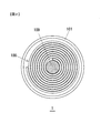
- FIG. 1 is a cross-sectional view showing an embodiment of a lithium ion battery 1 according to the present invention.
- FIG. 2 is a cross-sectional view taken along the line AA in FIG.
- FIG. 3 is a cross-sectional view showing a part of the wound electrode group 100.
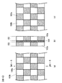
- FIG. 4 is a diagram schematically showing the configuration of the positive electrode mixture layer 103 formed on the positive electrode 121.
- FIG. 5 is a diagram showing the positive electrode current collector 121 when the positive electrode mixture layer 103 is divided into strips.
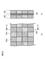
- FIG. 6 is a diagram showing an active material arrangement example when three types of active materials are used.
- FIG. 7 is a diagram illustrating the positive electrode current collector 121 when the second positive electrode mixture layer 212 is stacked on the positive electrode mixture layer 103.
- FIG. 8 is a diagram showing a dE / dT curve in the case of LiMn 2 O 4 alone.
- FIG. 9 is a diagram showing a dE / dT curve when LiMn 2 O 4 and Li 1.06 Mn 1.89 Al 0.05 O 4 are divided at a ratio of 15:85 and applied to a current collector foil. is there.
- FIG. 10 is a diagram showing a dE / dT curve when LiMn 2 O 4 and Li 1.06 Mn 1.89 Al 0.05 O 4 are divided at a ratio of 15:85 and applied to a current collector foil. is there.
- FIG. 11 is a diagram showing a dE / dT curve of the negative electrode current collector 122.
- FIG. 12 is a diagram showing a dE / dT curve when the entire lithium capacity range is used for both the positive electrode and the negative electrode.
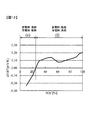
- FIG. 13 is a diagram showing a dE / dT curve when the region (a) in FIG. 10 and the region (d) in FIG. 11 are used.
- FIG. 14 is a diagram showing a dE / dT curve when the region (b) in FIG. 10 and the region (c) in FIG. 11 are used.
- FIG. 1 is a cross-sectional view showing a first embodiment of a lithium ion battery 1 according to the present invention.
- FIG. 2 is a cross-sectional view taken along the line AA in FIG.
- the wound type lithium ion battery 1 shown in FIG. 1 will be described as an example.
- the present invention is not limited to the wound type, and can be applied to a stacked type.
- the shape is not limited to a cylindrical shape, and may be a square shape or other shapes.
- a laminated unit composed of a positive electrode 121, a separator 107, a negative electrode 122, and a separator 107 is wound around an axis 109 to form a wound electrode group 100, which is stored in a battery can 101. It has a structure.
- the shaft center 109 may be removed after the wound electrode group 100 is formed and may not exist.
- FIG. 3 shows a partial cross section of the wound electrode group 100.
- FIG. 3 shows two layers (100a, 100b) of the wound electrode group 100, and the outer layer 100b is wound outside the inner layer 100a.
- the positive electrode 121 that is a constituent element of the wound electrode group 100 includes a positive electrode current collector foil 104 and a positive electrode mixture layer 103 formed on the positive electrode current collector foil 104.
- the positive electrode mixture layer 103 includes a positive electrode active material, a conductive additive, and a binder.
- the negative electrode 122 includes a negative electrode current collector foil 106 and a negative electrode mixture layer 105 formed on the negative electrode current collector foil 106.
- the negative electrode mixture layer 105 includes a negative electrode active material, a conductive additive, and a binder. Note that the mixture layers 103 and 105 may contain additives in addition to the active material, the conductive auxiliary agent, and the binder.
- FIG. 4 is a diagram schematically showing the configuration of the positive electrode mixture layer 103 formed on the positive electrode 121.
- 4A is a view showing the positive electrode mixture layer 103 formed on one surface of the positive electrode 121
- FIG. 4B is a cross-sectional view taken along the line BB
- FIG. 4C is the other surface of the positive electrode 121. It is a figure which shows the formed positive mix layer 103.
- FIG. In the present embodiment, a plurality of types of active materials are used for the positive electrode mixture layer 103, and the plurality of types of active materials are separately divided and applied onto the positive electrode current collector foil 104. In the example shown in FIG.
- the positive electrode active material two types are used as the positive electrode active material, one active material is included in the mixture layer region indicated by reference numeral 103a, and the other active material is included in the mixture layer region indicated by reference numeral 103b. It is included.
- the mixture layer region 103b is disposed in a region corresponding to the mixture layer region 103a on one surface, and the mixture layer region 103b on one surface is formed.
- the mixture layer region 103a is arranged in a region corresponding to the above. This is because the heat generation in the mixture layer region 103a and the heat generation in the mixture layer region 103b are not necessarily equal, so that the temperature distribution of the entire electrode during heat generation is made as uniform as possible. Moreover, it is preferable that the area of the mixture layer regions 103a and 103b is small.
- the positive electrode mixture layer 103 is divided into a lattice shape, and the mixture layer regions 103a and the mixture layer regions 103b are alternately arranged.
- the mixture layer region 103b is disposed in a region corresponding to the mixture layer region 103a on one surface
- the mixture layer region 103a is disposed in a region corresponding to the mixture layer region 103b on one surface. Is desirable.
- the positive electrode current collector foil 104 is generally an aluminum foil, and the negative electrode current collector 106 is generally a copper foil.
- a conductive material such as a nickel foil or a stainless steel foil may be used, but is not limited thereto. .
- FIG. 6 shows an active material arrangement example when three types of active materials are used. Different active materials are used for the active material regions 103d, 103e, and 103f. By changing the ratio of the area occupied by the active material regions 103d, 103e, and 103f, the lithium capacity region corresponding to the heat absorption during discharging or charging can be arbitrarily adjusted in the dE / dT curve (described later) of the positive electrode. Is possible.
- the active material regions 103d, 103e, and 103f preferably have a small area.
- Examples of the active material constituting the positive electrode mixture layer 103 include LiCoO 2 , LiMn 2 O 4 , LiNiO 2 , LiAlO 2 , LiNi 0.5 Mn 0.5 O 2 , LiNi 1/3 Mn 1/3 Co 1.
- 4 and 5 two types of active materials are selected from these and applied to the active material regions 103a and 103b, respectively. In the case of FIG. 6, three types of active materials are selected from these and applied to the active material regions 103d to 103f, respectively. Further, the active material is not limited to these, and can be appropriately changed to other materials.
- the second positive electrode mixture layer 212 is stacked on the positive electrode mixture layer 103 illustrated in FIG. 6.
- a positive electrode mixture layer as shown in FIGS. 4 to 6 may be used, or a positive electrode mixture layer containing one kind of active material may be used.
- the number of mixture layers may be three or more.
- the electrode structure configured by a plurality of active materials divided into strips and grids has been described.
- the shape of the partition is not limited to strips and grids, and is circular. Of course, polygonal shapes and other shapes are also acceptable. Further, the entire surface does not necessarily have to be uniformly divided, and a part of the electrodes may be combined in a circular shape and a part of the electrode in a lattice shape.
- the positive electrode mixture layer 103 includes a plurality of types of active materials
- the negative electrode mixture layer 105 may include a plurality of types of active materials, or the positive electrode mixture layer 103 and the negative electrode mixture may be combined. Both agent layers 105 may be configured to include a plurality of types of active materials.
- the thickness of the mixture layer may be the same or not on both the front and back surfaces of the positive electrode current collector foil 104. Further, the positive electrode mixture layer 103 may be provided only on one side of the positive electrode current collector foil 104.
- the negative electrode is the same as the positive electrode, and a plurality of types of active materials are selected and divided to form an electrode, and the area ratio is adjusted to discharge or charge in the dE / dT curve of the negative electrode. It is possible to arbitrarily adjust the region corresponding to the endothermic heat.
- Examples of the active material for the negative electrode mixture layer 105 include natural graphite, artificial graphite such as mesocarbon microbeads (MCMB), mesophase pitch-based carbon fiber (MCF), vapor grown carbon fiber (VGCF), and Nb.
- the separator 107 needs to prevent direct contact between the positive electrode and the negative electrode and maintain ionic conductivity, but in a battery using an electrolytic solution, a porous material having a pore is often used.
- a porous material having a pore examples include polyolefin, polyethylene, and polypropylene, but are not limited thereto.
- the electrolyte (not shown in FIG. 1) exists in the pores of the separator 107, which is a porous material, and the positive electrode mixture layer 103 and the negative electrode mixture layer 105.
- the electrolytic solution functions as an ion conductive layer, and a non-aqueous electrolyte is used in the lithium ion battery.
- the electrolyte in the lithium ion battery is composed of a lithium salt such as LiPF 6 , LiBF 4 , LiClO 4 and a solvent such as ethylene carbonate or diethyl carbonate.
- the electrolytic solution is not limited to liquid or gel but may be solid.
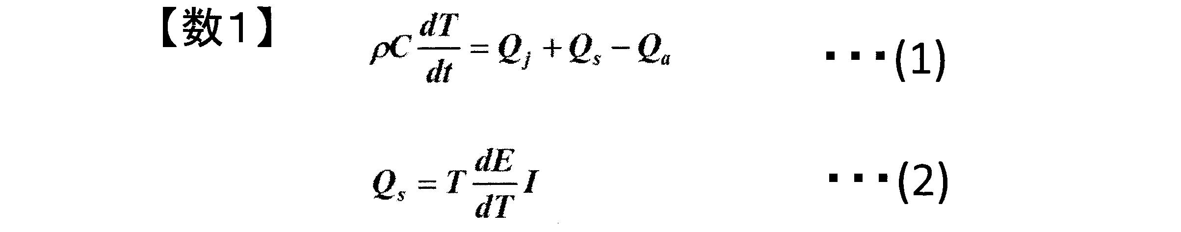
- the heat balance of a lithium ion battery is represented by Formula (1), (2).
- ⁇ is density and C is specific heat.
- the first term Qj on the right side represents Joule heat generation
- the second term Qs represents heat generation due to entropy change (entropy heat generation)
- the third term Qa represents heat dissipation.
- Joule heat Qj is proportional to the internal resistance of the battery and the square of the current.
- the heat generation Qs due to the entropy change is expressed by the product of the temperature T, the rate of change dE / dT of the potential with respect to the temperature, and the current I.
- the current I is positive when charging and negative when discharging when viewed as a whole battery.
- the exothermic Qs due to the entropy change is due to the entropy change when lithium ions are inserted into and desorbed from the lithium ion site.
- the entropy exotherm Qs can be either positive (exothermic) or negative (endothermic) depending on the sign of dE / dT and current I.
- the positive electrode mixture layer 103 and the negative electrode mixture layer 105 are composed of a plurality of types of active materials, a plurality of types of lithium ion sites corresponding to the respective active materials are formed, and entropy is generated.
- the exothermic Qs also varies depending on the type of active material.
- the entropy heat generation Qs at the time of charging and discharging is a value based on the entropy heat generation of each active material. Therefore, by combining a plurality of types of active materials and adjusting their amounts, it is possible to adjust the range of charge / discharge depth at which the value of entropy heat generation is negative. By performing such adjustment, it is possible to suppress the heat generation of the battery, and it is possible to suppress the deterioration of the battery due to the temperature rise.
- FIG. 9 shows a dE / dT curve obtained when LiMn 2 O 4 and Li 1.06 Mn 1.89 Al 0.05 O 4 were divided at a ratio of 15:85 and applied to a current collector foil. This is calculated by simulation calculation taking into account the energy when lithium ions are inserted into and desorbed from the site. More specifically, a model considering the lithium ion site energy of each active material, the repulsion energy between lithium ions, the number of crystal coordination of the active material, and the like was constructed by a statistical mechanical method, and calculated by simulation.
- the vertical axis indicates dE / dT
- the horizontal axis indicates the lithium capacity in the positive electrode. That is, the lithium capacity is 1 when lithium ions are inserted into all lithium ion sites, and the lithium capacity is 0 when lithium ions are desorbed from all lithium ion sites.
- the lithium capacity in the positive electrode increases as 0 ⁇ 1 during discharging and decreases as 1 ⁇ 0 during charging.
- dE / dT has a lithium capacity in the range of 0.0 to about 0.2 and about 0.45 to about 0.65.
- dE / dT > 0, and in the range of about 0.2 to about 0.45 and about 0.65 to 1.0, dE / dT ⁇ 0. Since the current I in the formula (2) takes a negative value during discharge at the positive electrode, the entropy heat generation is 0.0 to about 0.2 and dE / dT> 0 and about 0.45 to about 0.00.
- dE / dT ⁇ 0 is about 0.2 to about 0.45
- about 0.65 to 1.0 is a positive value (exothermic).
- the entropy heat generation is 0.0 to about 0.2 where dE / dT> 0 and about 0.45 to about 0.65.
- a positive value (exotherm) is obtained, and a negative value (endotherm) is obtained at about 0.2 to about 0.45 and about 0.65 to 1.0 where dE / dT ⁇ 0.
- the heat generation region is larger than the heat absorption region during discharge. That is, in a battery in which the active material of the positive electrode mixture layer 103 is composed of LiMn 2 O 4 alone, when discharging is performed in the entire lithium capacity region, the average entropy heat generation becomes positive and the heat generation amount (Joule heat generation Qj and entropy heat generation) The sum of Qs) is large.
- dE / dT is the rate of change of potential with respect to temperature
- dE / dT for the positive electrode active material 103 as a whole is dE / dT of LiMn 2 O 4 alone and Li 1.06 Mn 1.89 Al 0.05 O 4 alone. It is not simply the sum of dE / dT.
- the fact that the combined endothermic regions are spread over a wide lithium capacity region can be an index.
- the energy when lithium ions enter the lithium ion site can also be used as one of the indicators. It is known that when the active materials having different energies are combined, the boundary position between the heat absorption and the heat generation is shifted.
- the example shown in FIG. 9 is a configuration for suppressing the amount of heat generated during discharging, and entropy heat generation becomes positive (heat generation) in a wide range of lithium capacity 0.0 to about 0.65 during charging.
- an uninterruptible power supply device may be used as a battery for which heat generation during discharge is particularly desired to be suppressed.
- a battery application for which heat generation during charging is particularly desired to be suppressed there is an apparatus that requires rapid charging.
- FIG. 10 shows the same dE / dT curve as the dE / dT curve shown in FIG. 9 described above. That is, the positive electrode current collector 121 formed by dividing LiMn 2 O 4 and Li 1.06 Mn 1.89 Al 0.05 O 4 at a ratio of 15:85 and coating the positive electrode current collector foil 104. dE / dT curve.
- FIG. 10 shows the same dE / dT curve as the dE / dT curve shown in FIG. 9 described above. That is, the positive electrode current collector 121 formed by dividing LiMn 2 O 4 and Li 1.06 Mn 1.89 Al 0.05 O 4 at a ratio of 15:85 and coating the positive electrode current collector foil 104. dE / dT curve.
- FIG. 10 shows the same dE / dT curve as the dE / dT curve shown in FIG. 9 described above. That is, the positive electrode current collector 121 formed by dividing LiMn 2 O 4 and Li 1.06
- FIG. 11 is a diagram showing a dE / dT curve of the negative electrode current collector 122 (the rate of change in potential with respect to temperature when metallic lithium is used as a reference), and the negative electrode using mesocarbon microbeads (MCMB) as an active material. The actual measurement value when applied to the current collector foil 106 is shown.
- MCMB mesocarbon microbeads
- the dE / dT curve for the entire battery is obtained by subtracting the dE / dT of the negative electrode from the dE / dT of the positive electrode, resulting in a dE / dT curve as shown in FIG.
- the horizontal axis represents the charging depth (SOC: “state” of “charge”).
- the current I during discharge is a negative value, so heat is generated in the region (e) and heat is absorbed in the region (f).
- the heat generation (see FIG. 12) is almost zero.
- the region (e) since the current I is a positive value, the region (e) generates heat and the region (f) generates heat. Therefore, in the case of such a configuration, a heat generation region always exists in the entire range (0 to 100%) of the charging depth.
- each electrode is configured so that only the region (a) of FIG. 10 is used for the positive electrode and only the region (d) of FIG. 11 is used for the negative electrode.
- the entropy heat generation during discharge is always negative, that is, endothermic at all charging depths.
- the amounts of the positive electrode active material and the negative electrode active material are adjusted so that the number and the number of lithium ion sites in the region (d) are equal.
- the width of the lithium capacity range of the region (a) in the positive electrode is about 0.65
- the width of the lithium capacity range of the region (d) in the negative electrode is about 0.79. It is. Therefore, by increasing the coating amount to (0.79 / 0.65) times the coating amount of the positive electrode mixture layer when the data of FIGS. 10 and 11 are obtained, the region (a) The number of lithium ion sites in the region and the number of lithium ion sites in the region (d) can be made the same. As a result, it becomes possible to set the regions (a) and (d) where the entropy heat generation becomes endothermic during discharge in the range of 0% to 100% charge depth.
- the dE / dT curve of the entire battery in that case is as shown in FIG. Since the current I takes a negative value during discharging, the heat generation due to the entropy change becomes a negative value at the entire charging depth (0 to 100%) and becomes endothermic. As a result, the heat generation of the battery can be suppressed and the deterioration can be suppressed at the full charge depth during discharge.
- the range of the charging depth (SOC) 0% to 100% shown in FIG. 13 corresponds to the region (a) in FIG. 10, so when selecting a plurality of types of active materials, the region (a) Is preferably selected to be as large as possible.
- FIG. 14 shows the dE / dT curve of the entire battery when configured in this way. Since the current I takes a positive value during charging, according to this configuration, the heat derived from the entropy change can be absorbed by the entire charging depth (0 to 100%).
- the active material of the positive electrode is a composite of LiMn 2 O 4 and Li 1.06 Mn 1.89 Al 0.05 O 4 and the negative electrode active material is MCMB
- the battery configuration for making entropy heat generation negative (endothermic) at all charge depths has been described. That is, in order to make entropy heat generation negative (endothermic) during discharge, 0 ⁇ x ⁇ 0 in the positive electrode (complex of LiMn 2 O 4 and Li 1.06 Mn 1.89 Al 0.05 O 4 ).
- the battery is preferably configured to include a lithium capacity range of .65 and a negative electrode (MCMB) that includes a lithium capacity range of 0.21 ⁇ x ⁇ 1.0.
- the positive electrode includes a lithium capacity range of 0.65 ⁇ x ⁇ 1.0, and the negative electrode has a lithium capacity of 0 ⁇ x ⁇ 0.21.
- the battery is preferably configured to include the range.
- Li 1.156 Mn 1.844 O 4 the lithium capacity range of 0 ⁇ x ⁇ 0.3 is preferably included, and Li 1.06 Mn 1.89 Al 0.05
- O 4 it is preferable to include the lithium capacity range of 0 ⁇ x ⁇ 0.65.
- the lithium capacity range of 0.5 ⁇ x ⁇ 1.0 is included when LiNi 0.8 Co 0.15 Al 0.05 O 2 is used for the positive electrode.
- LiNi 0.8 Co 0.2 O 2 it is preferable to include a lithium capacity range of 0.4 ⁇ x ⁇ 1.0 .
- the lithium capacity range of 0.3 ⁇ x ⁇ 1.0 may be included, and Li 1.06 Mn 1.89 Al 0.05 O 4
- the lithium ion battery according to the present invention includes the positive electrode 121 in which the positive electrode mixture layer 103 including the active material capable of occluding and releasing lithium ions is formed on the positive electrode current collector foil, and occluding lithium ions. And a negative electrode 122 in which a negative electrode mixture layer 105 containing a releasable active material is formed on a negative electrode current collector foil, a separator disposed between the positive electrode 121 and the negative electrode 122, and an electrolytic solution.
- At least one of the layer 103 and the negative electrode mixture layer 105 includes a plurality of types of active materials, and the mixture layer including a plurality of types of active materials has a lithium capacity range in which entropy heat generation during charging is negative, Lithium capacity of the mixture layer containing any one of the above is wider than the lithium capacity range in which entropy heat generation during charging is negative, or entropy heat generation during discharge is negative Circumference is in the mix layer containing any one of a plurality of types of active materials, wider than the lithium capacity range of the discharge time entropy heat is negative, characterized in that. With such a configuration, heat generation during charging or discharging can be suppressed.
- the mixture layer containing a plurality of types of active materials has a lithium capacity range in which entropy heat generation during discharge is negative, and the mixture layer contains any one of the plurality of types of active materials during discharge.
- the entropy heat generation is set to be wider than the lithium capacity range in which the entropy heat generation is negative
- the entropy heat generation during the discharge of the positive electrode mixture layer is negative
- the entropy heat generation during the discharge of the negative electrode mixture layer is negative
- the formation amounts of the positive electrode mixture layer and the negative electrode mixture layer are set so that the lithium capacity range can be set in the range of 0% to 100% charge depth.
- the entropy heat generation at the time of discharge can be made negative in the range of the charging depth from 0% to 100%, and the heat generation at the time of discharge can be suppressed.
- the mixture layer containing a plurality of types of active materials is a mixture layer in which the lithium capacity range in which entropy heat generation during charging is negative includes any one of the plurality of types of active materials.
- the entropy heat generation during charging is wider than the lithium capacity range in which the entropy heat generation is negative
- the entropy heat generation during charging of the positive electrode mixture layer is negative
- the entropy heat generation during charging of the negative electrode mixture layer is negative.
- the amount of formation of the positive electrode mixture layer and the negative electrode mixture layer is set so that the lithium capacity range can be set in the range of 0% to 100% charge depth.
- the entropy heat generation during charging can be made negative in the range of the charging depth from 0% to 100%, and the heat generation during charging can be suppressed.
- the mixture layer containing a plurality of types of active materials has, for example, two mixture layer regions 103a and 103b divided for each type of active material, as shown in FIG. Is included in the mixture layer region 103a, and the other active material is included in the mixture layer region 103b.
- the dE / dT characteristic of the composite of LiMn 2 O 4 and Li 1.06 Mn 1.89 Al 0.05 O 4 as shown in FIG. 10
- An optimal distribution (15:85) is set based on the dE / dT characteristics of 1.06 Mn 1.89 Al 0.05 O 4 .
- lithium ions When two types of active materials are uniformly mixed and applied to form a positive electrode mixture layer, it is generally known that the way in which lithium ions enter varies depending on the location, for example, at the center and outside of the cylinder. It has been. As a result, a heat generation distribution occurs, which may cause deterioration of the battery. Therefore, by dividing and applying multiple active materials, for example, lithium ions can be entered by focusing on active materials that are difficult for lithium ions to enter. Can be made uniform and heat generation can be suppressed.
- two (or a plurality of) active materials may be mixed to form a uniform positive electrode mixture layer.
- the negative electrode mixture layer can be considered in the same manner as the positive electrode mixture layer.
Landscapes
- Chemical & Material Sciences (AREA)
- Engineering & Computer Science (AREA)
- Chemical Kinetics & Catalysis (AREA)
- Electrochemistry (AREA)
- General Chemical & Material Sciences (AREA)
- Composite Materials (AREA)
- Materials Engineering (AREA)
- Manufacturing & Machinery (AREA)
- Secondary Cells (AREA)
- Battery Electrode And Active Subsutance (AREA)
Abstract
リチウムイオン電池は、リチウムイオンを吸蔵および放出可能な活物質を含む正極合剤層を正極集電箔に形成した正極と、リチウムイオンを吸蔵および放出可能な活物質を含む負極合剤層を負極集電箔に形成した負極と、正極と負極との間に配置されたセパレータと、電解液と、を備え、正極合剤層および負極合剤層の少なくとも一方は複数種類の活物質を含む。複数種類の活物質を含む合剤層は、充電時エントロピー発熱が負となるリチウム容量範囲が、複数種類の活物質の内のいずれか一つを含む合剤層における、充電時エントロピー発熱が負となるリチウム容量範囲よりも広くなっている。または、放電時エントロピー発熱が負となるリチウム容量範囲が、複数種類の活物質の内のいずれか一つを含む合剤層における、放電時エントロピー発熱が負となるリチウム容量範囲よりも広くなっている。
Description
本発明は、リチウムイオン電池、およびリチウムイオン電池用電極に関する。
近年、化石燃料の資源的節約や地球温暖化などを背景に、省エネルギーの推進が求められており、二次電池の中でも大容量で小型のリチウムイオン電池は省エネルギー社会の実現に重要な蓄電デバイスとして期待されている。そのため、携帯情報端末やコードレス電子機器電源としての民生用途、電動工具の電源や電力貯蔵用といった産業用途、電気自動車やハイブリッド電気自動車といった車載用途を中心に需要が拡大している。また、このような様々な用途に応じて、高容量化に代表される電池性能向上に向けた開発が加速している。
リチウムイオン電池を実用化するには、電池の高性能化とともに、信頼性、安全性の向上が重要である。特に、高性能化にともない、充放電時の発熱量も大きくなっている。充放電時の発熱が大きいと、電池の温度が上昇し、電池の寿命が低下するため、いかに発熱を抑制するかが重要な課題となっている。
リチウムイオン電池の発熱要因としては、ジュール熱とエントロピー変化に由来する発熱(以下、エントロピー発熱)とが知られている。ジュール熱とは、電池の内部抵抗と電流の二乗に比例する発熱であり、必ず正の値、つまり発熱となる。一方、エントロピー発熱とは、充放電により、リチウムイオンの移動に伴って変化するエントロピー変化に由来する発熱であり、電極を構成する物質に応じて、また、電流の向きによって正負両方の値を取り得る。つまり、エントロピー発熱とは、発熱の場合もあり、吸熱の場合もある。また、その値は充放電深度によって決まる。
例えば、特許文献1には、正極集電箔の一方の面に、充電時に発熱し、放電時に吸熱する活性炭の粒子を含むキャパシタ正極電極層が形成されたキャパシタ電極と、正極集電箔の他方の面に、充電時に吸熱し、放電時に発熱するリチウム含有金属化合物の粒子を含んだ電池正極を備えた電力貯蔵デバイス用正極について説明されている。このような構成とすることで、充電時と放電時で吸熱と発熱が表のキャパシタ正極とは逆になる電池正極を正極集電箔の裏に配置することで、充電時の局部的な温度上昇や局部的な温度変化を緩和している。
しかしながら、特許文献1に記載の技術は、充放電時の局部的な温度上昇や局部的な温度変化を緩和するものであるが、充電深度0%~100%におけるエントロピー発熱の値が負になる範囲は決まっており、その範囲を調節することはできない。そのため、全充電深度で充電を行った場合の全体の発熱量を減少させるのは難しい。
本発明の第1の態様によると、リチウムイオン電池は、リチウムイオンを吸蔵および放出可能な活物質を含む正極合剤層を正極集電箔に形成した正極と、リチウムイオンを吸蔵および放出可能な活物質を含む負極合剤層を負極集電箔に形成した負極と、正極と負極との間に配置されたセパレータと、電解液と、を備え、正極合剤層および負極合剤層の少なくとも一方は複数種類の活物質を含み、複数種類の活物質を含む合剤層は、充電時エントロピー発熱が負となるリチウム容量範囲が、複数種類の活物質の内のいずれか一つを含む合剤層における、充電時エントロピー発熱が負となるリチウム容量範囲よりも広い、または、放電時エントロピー発熱が負となるリチウム容量範囲が、複数種類の活物質の内のいずれか一つを含む合剤層における、放電時エントロピー発熱が負となるリチウム容量範囲よりも広い。
本発明の第2の態様によると、リチウムイオン電池用電極は、集電箔と、複数種類の活物質を含む合剤層と、を備え、合剤層は、充電時のエントロピー発熱が負となるリチウム容量範囲が、複数種類の活物質の内のいずれか一つを含む合剤層における、充電時エントロピー発熱が負となるリチウム容量範囲よりも広い、または、放電時エントロピー発熱が負となるリチウム容量範囲が、複数種類の活物質の内のいずれか一つを含む合剤層における、放電時エントロピー発熱が負となるリチウム容量範囲よりも広い。
本発明の第2の態様によると、リチウムイオン電池用電極は、集電箔と、複数種類の活物質を含む合剤層と、を備え、合剤層は、充電時のエントロピー発熱が負となるリチウム容量範囲が、複数種類の活物質の内のいずれか一つを含む合剤層における、充電時エントロピー発熱が負となるリチウム容量範囲よりも広い、または、放電時エントロピー発熱が負となるリチウム容量範囲が、複数種類の活物質の内のいずれか一つを含む合剤層における、放電時エントロピー発熱が負となるリチウム容量範囲よりも広い。
本発明によれば、充電時または放電時の発熱を抑えることができる。
-第1の実施の形態-
図1は、本発明に係るリチウムイオン電池1の第1の実施の形態を示す断面図である。また、図2は、図1のA-A断面図である。なお、本実施の形態では、図1に示す捲回型リチウムイオン電池1を例に説明するが、本発明は、捲回型に限らず積層型にも適用でき、また、電池形状に関しては、円筒型に限らず角型その他の形状でも良い。
図1は、本発明に係るリチウムイオン電池1の第1の実施の形態を示す断面図である。また、図2は、図1のA-A断面図である。なお、本実施の形態では、図1に示す捲回型リチウムイオン電池1を例に説明するが、本発明は、捲回型に限らず積層型にも適用でき、また、電池形状に関しては、円筒型に限らず角型その他の形状でも良い。
円筒型リチウムイオン電池1は、正極121、セパレータ107、負極122およびセパレータ107からなる一積層単位を、軸心109に捲回して捲回電極群100を形成し、これを電池缶101に収納した構造を有している。なお、軸心109に関しては、捲回電極群100を作成後に取り外され、存在しない構成のものもある。
図3は、捲回電極群100の一部の断面を示したものである。図3では、捲回電極群100の2層分(100a,100b)を示したものであり、内側層100aの外側に外側層100bが捲回されている。捲回電極群100の構成要素である正極121は、正極集電箔104と、正極集電箔104上に形成された正極合剤層103とにより構成される。正極合剤層103は、正極活物質や導電助剤、バインダを含む。負極122は、負極集電箔106と、負極集電箔106上に形成された負極合剤層105とにより構成される。負極合剤層105は、負極活物質や導電助剤、バインダを含む。なお、合剤層103、105は活物質や導電助剤、バインダの他に、添加物等を含んでも良い。
図4は、正極121に形成された正極合剤層103の構成を模式的に示す図である。図4において、(a)は正極121の一方の面に形成された正極合剤層103を示す図であり、(b)はB-B断面図、(c)は正極121の他方の面に形成された正極合剤層103を示す図である。本実施形態では、正極合剤層103に複数種類の活物質が用いられ、複数種類の活物質は、それぞれ独立して区分けして正極集電箔104上に塗布されている。図4に示す例では、2種類の活物質が正極活物質として用いられ、符号103aで示す合剤層領域に一方の活物質が含まれ、符号103bで示す合剤層領域に他方の活物質が含まれている。図4(c)に示す他方の面の正極合剤層103では、一方の面の合剤層領域103aに対応する領域に合剤層領域103bが配置され、一方の面の合剤層領域103bに対応する領域に合剤層領域103aが配置されている。これは、合剤層領域103aにおける発熱と合剤層領域103bにおける発熱とが等しいとは限らないので、発熱時における電極全体の温度分布ができるだけ均一となるようにするためである。また、合剤層領域103a,103bの面積は小さい方が好ましい。
なお、図4では、正極合剤層103を格子状に区分けし、合剤層領域103aと合剤層領域103bとを交互に配置したが、図5に示すように短冊状に区分けしても良い。この場合も、一方の面の合剤層領域103aに対応する領域に合剤層領域103bが配置され、一方の面の合剤層領域103bに対応する領域に合剤層領域103aが配置されるのが望ましい。
正極集電箔104はアルミニウム箔、負極集電体106は銅箔が一般的に使用されるが、ニッケル箔、ステンレス箔などの導電性材料を用いても良く、またこれらに限られるものではない。
図6は、3種類の活物質を用いる場合の活物質配置例を示したものである。活物質領域103d、103e、103fには、それぞれ異なる活物質が用いられる。活物質領域103d、103e、103fの占める面積の比を変化させることで、正極のdE/dT曲線(後述する)において、放電時または充電時の吸熱に相当するリチウム容量領域を任意に調節することが可能となる。また、活物質領域103d、103e、103fの面積は小さい方が好ましい。
正極合剤層103を構成する活物質材料として、例えば、LiCoO2、LiMn2O4、LiNiO2、LiAlO2、LiNi0.5Mn0.5O2、LiNi1/3Mn1/3Co1/3O2、LiMyMn2-yO4(M=Cr、Fe、Co、Ni、Cu)、LiNiVO4、LiCoVO4、LiMnVO4、LiFePO4、LiCoPO4、LiMnPO4、LiNiPO4、Li2FeSiO4、LiNi0.8Co0.15Al0.05O2、LiNi0.8Co0.2O2、Li0.156Mn1.844O4、Li0.06Mn1.89Al0.05O4などが使用される。図4,5の場合には、これらの中から2種類の活物質が選択され、それぞれ活物質領域103a、103bに塗布される。また、図6の場合には、これらの中から3種類の活物質が選択され、それぞれ活物質領域103d~103fに塗布される。また、活物質材料はこれらに限るものではなく、適宜その他の材料に変えることができる。
なお、図4~6に示す例では、集電箔104,106の表裏両面に合剤層を一層だけ形成したが、図7に示すように二層以上形成するようにしても良い。図7に示す例では、図6に示した正極合剤層103の上に、第二の正極合剤層212を積層した。第二の正極合剤層212には、図4~6に示したような正極合剤層を用いても良いし、一種類の活物質を含む正極合剤層としても良い。さらには、合剤層の層数を三層以上としても良い。
なお、上述した実施の形態では、短冊状、格子状に区分けして複数の活物質で構成する電極構造について説明したが、その区分けの形状は短冊状、格子状に限定するものではなく、円形や多角形、またその他の形状でももちろん良い。また、全面が必ずしも均一に区分けられている必要はなく、電極の一部は円形、一部は格子状のように組み合わせても良い。
以下では、正極合剤層103が複数種類の活物質を含む場合を例に説明するが、負極合剤層105が複数種類の活物質を含む構成でも良いし、正極合剤層103および負極合剤層105の両方が複数種類の活物質を含む構成であっても良い。また、合剤層の厚さに関しては、正極集電箔104の表裏両面で等しくても、等しくなくてもどちらでも良い。また、正極集電箔104の片面側にのみ正極合剤層103を設けるようにしても良い。負極の場合も、正極の場合と同様であり、複数種類の活物質を選択して区分けして電極を構成し、その面積比を調節することで、負極のdE/dT曲線において、放電または充電時の吸熱に相当する領域を任意に調節することが可能となる。
負極合剤層105の活物質材料としては、例えば天然黒鉛や、メソカーボンマイクロビーズ(MCMB)、メソフェーズピッチベース炭素繊維(MCF)、気相成長炭素繊維(VGCF)などの人造黒鉛、また、Nb2O5、TiO2、Li4/3Ti5/3O4、WO2、MoO2、Fe2O3、Li2.6Co0.4N3、Li4Ti5O12などの酸化物、Li2.6Co0.4N3、に代表されるLi3-xMxN(M=Co、Ni、Cu)で表される窒化物、Al、Si、Ge、Sn、Pb、As、Sb等とLiとの合金材料などが使用される。また、活物質材料はこれらに限るものではなく、適宜その他の材料に変えることができる。負極合剤層105も正極合剤層103と同様に、複数種類の活物質材料で構成されても良い。
セパレータ107は、正極と負極が直接接触することを防ぎ、イオン導電性を保持する必要があるが、電解液を用いる電池では、細孔部を有する多孔性材料を用いることが多い。この多孔性材料として、ポリオレフィンやポリエチレン、ポリプロピレンに代表されるが、これらに限るものではない。
電解液(図1では図示せず)は、多孔性材料であるセパレータ107や、正極合剤層103、負極合剤層105の細孔部に存在する。ここで、電解液はイオン導電層として働き、リチウムイオン電池では、非水溶液系電解質が用いられる。リチウムイオン電池内の電解液はLiPF6、LiBF4、LiClO4、のようなリチウム塩とエチレンカーボネイトやジエチルカーボネートのような溶媒によって構成される。また、電解液は液体やゲルに限らず、固体でも良い。
ところで、リチウムイオン電池の熱収支は式(1)、(2)で表される。式(1)において、ρは密度、Cは比熱である。式(1)の右辺第一項Qjはジュール発熱、第二項Qsはエントロピー変化による発熱(エントロピー発熱)、第三項Qaは放熱を表している。ジュール発熱Qjは電池の内部抵抗と電流の二乗に比例する。一方、エントロピー変化による発熱Qsは温度Tと、電位の温度に対する変化率dE/dTと、電流Iとの積で表される。電流Iは、電池全体で見ると、充電のとき正、放電のとき負となる。
エントロピー変化による発熱Qsは、リチウムイオンサイトにリチウムイオンの挿入、脱離する際のエントロピー変化に起因するものである。式(2)から、エントロピー発熱Qsは、dE/dTおよび電流Iの符号に応じて、正(発熱)にも負(吸熱)にもなり得る。上述したように、正極合剤層103や負極合剤層105は複数種類の活物質から構成されるため、それぞれの活物質に応じた複数種類のリチウムイオンサイトが形成されることになり、エントロピー発熱Qsも活物質の種類に応じてそれぞれ異なることになる。
合剤層を複数種類の活物質で構成した場合、充電時および放電時のエントロピー発熱Qsは各活物質のエントロピー発熱に基づいた値となる。そのため、複数種類の活物質を組み合わせ、それらの量を調整することにより、エントロピー発熱の値が負となる充放電深度の範囲を調整することができる。このような調整を行うことにより電池の発熱の抑制が可能となり、温度上昇に起因する電池の劣化を抑制することができる。
一例として、正極活物質としてLiMn2O4のみを用いた場合と、2種類の活物質LiMn2O4、Li1.06Mn1.89Al0.05O4を用いた場合について説明する。図8は、LiMn2O4単独のdE/dT曲線、すなわち、金属リチウムを基準とした場合のLiMn2O4の電位について、電位の温度に対する変化率の曲線を示したものである。図8の曲線は、LiMn2O4を含む合剤層に対する実測値である。図9は、LiMn2O4とLi1.06Mn1.89Al0.05O4とを15:85の割合で区分けして集電箔に塗布した場合のdE/dT曲線を、リチウムイオンサイトにリチウムイオンが挿入・脱離する際のエネルギー等を考慮して、シミュレーション計算により算出したものである。より具体的には、統計力学的手法により、各活物質のリチウムイオンサイトエネルギー、リチウムイオン間の反発エネルギー、活物質の結晶配位数などを考慮したモデルを構築し、シミュレーションにより算出した。
図8,9において、縦軸はdE/dT、横軸は正極内のリチウム容量を示している。すなわち、リチウムイオンサイトの全てにリチウムイオンが挿入された場合にはリチウム容量は1であり、リチウムイオンサイトの全てからリチウムイオンが脱離している場合にはリチウム容量は0である。正極内におけるリチウム容量は、放電時には0→1のように増加し、充電時には1→0のように減少する。
図8に示すLiMn2O4単独の場合のdE/dT曲線では、dE/dTは、リチウム容量が0.0~約0.2、および、約0.45~約0.65の範囲にある場合にはdE/dT>0となり、約0.2~約0.45、および、約0.65~1.0の範囲にある場合にはdE/dT<0となる。式(2)の電流Iは正極での放電時には負の値となるので、エントロピー発熱は、dE/dT>0である0.0~約0.2、および、約0.45~約0.65では負の値(吸熱)となり、dE/dT<0である約0.2~約0.45、および、約0.65~1.0では正の値(発熱)となる。一方、正極での充電時の電流Iは正の値となるので、エントロピー発熱は、dE/dT>0である0.0~約0.2、および、約0.45~約0.65では正の値(発熱)となり、dE/dT<0である約0.2~約0.45、および、約0.65~1.0では負の値(吸熱)となる。
図8から分かるように、LiMn2O4単独の場合、全リチウム容量領域において、放電時は吸熱領域よりも発熱領域の方が大きい。つまり、正極合剤層103の活物質をLiMn2O4単独で構成した電池では、全リチウム容量領域で放電を行った場合、エントロピー発熱の平均は正となり、発熱量(ジュール発熱Qjとエントロピー発熱Qsとの和)が大きい。
一方、正極合剤層103の活物質として2種類の活物質LiMn2O4、Li1.06Mn1.89Al0.05O4を用いた場合には、図9に示すように、リチウム容量が0.0~約0.65の範囲においてdE/dT>0となり、約0.65~1.0の範囲においてdE/dT<0となる。すなわち、LiMn2O4とLi1.06Mn1.89Al0.05O4とを組み合わせた電極では、放電時の吸熱領域が増大していることが分かる。
これは、dE/dT特性の異なる2種類の活物質を用いることにより、吸熱領域が広くなったと考えられる。dE/dTは電位の温度に対する変化率であるので、正極活物質103全体に関するdE/dTは、LiMn2O4単独のdE/dTとLi1.06Mn1.89Al0.05O4単独のdE/dTとを単純に足し合わせたものとはならない。しかしながら、複数種類(例えば、2種類)の活物質を選択する場合には、それぞれの吸熱領域を合わせたものが、広いリチウム容量領域に拡がっていることが、一つの指標となり得る。リチウムイオンサイトにリチウムイオンが入るときのエネルギーも指標の一つとして用いることが可能である。このエネルギーが異なる活物質を組み合わせると、吸熱と発熱との境界位置がずれることが分かっている。
このように、本実施の形態では、異なる活物質を塗布することで、放電時もしくは充電時においてエントロピー発熱が吸熱となる領域(リチウム容量領域)を増やすことが可能となり、放電時もしくは充電時のどちらか一方において、電池の発熱を抑制し、電池の劣化を抑制することが可能となる。図9に示した例は、放電時における発熱量を抑制する場合の構成であり、充電時にはリチウム容量0.0~約0.65という広い範囲においてエントロピー発熱が正(発熱)となる。放電時の発熱を特に抑制したい電池の用途としては、例えば、無停電電源装置等がある。一方、充電時の発熱を特に抑制したい電池の用途としては、急速充電が必要な装置等がある。
-第2の実施の形態-
次に、本発明の第2の実施形態を図10~13を参照して説明する。図10は、上述した図9に示すdE/dT曲線と同一のdE/dT曲線を示したものである。すなわち、LiMn2O4とLi1.06Mn1.89Al0.05O4とを15:85の割合で区分けして正極集電箔104に塗布して構成された正極集電体121のdE/dT曲線である。一方、図11は負極集電体122のdE/dT曲線(金属リチウムを基準とした場合の、温度に対する電位の変化率)を示す図であり、メソカーボンマイクロビーズ(MCMB)を活物質として負極集電箔106に塗布した場合の実測値を示す。
次に、本発明の第2の実施形態を図10~13を参照して説明する。図10は、上述した図9に示すdE/dT曲線と同一のdE/dT曲線を示したものである。すなわち、LiMn2O4とLi1.06Mn1.89Al0.05O4とを15:85の割合で区分けして正極集電箔104に塗布して構成された正極集電体121のdE/dT曲線である。一方、図11は負極集電体122のdE/dT曲線(金属リチウムを基準とした場合の、温度に対する電位の変化率)を示す図であり、メソカーボンマイクロビーズ(MCMB)を活物質として負極集電箔106に塗布した場合の実測値を示す。
この二つの電極(正極、負極)を使用し、正極、負極ともに全リチウム容量範囲を使用するように、すなわち、正極のx=0と負極のx=1.0とが充電深度100%の状態となり、正極のx=1.0と負極のx=0とが充電深度0%の状態となるように電池を作製する。そのように電池を作製すると、電池全体でのdE/dT曲線は、正極のdE/dTから負極のdE/dTを引いたものとなり、図12に示すようなdE/dT曲線となる。なお、図12において、横軸は充電深度(SOC: state of charge)を表している。
例えば、SOC=100%におけるdE/dTは、正極のx=0におけるdE/dT=約0.13から、負極のx=1.0におけるdE/dT=約-0.07を引いた値であって、約0.2となる。また、SOC=25%におけるdE/dTは、正極のx=0.75におけるdE/dT=約-0.05から、負極のx=0.25におけるdE/dT=約-0.05を引いた値であって、ほぼ0となる。
放電状態を考える場合には、放電時の電流Iは負の値とされるので、領域(e)では発熱、領域(f)では吸熱となる。SOC=25%においては、正極における発熱(dE/dT=約-0.05)と負極による吸熱(dE/dT=約-0.05)とがほぼ等しくなり、正極と負極とを合わせた全体(図12参照)の発熱はほぼ0となる。一方、充電の場合には電流Iは正の値とされるため、領域(e)では吸熱、領域(f)では発熱となる。しがたって、このように構成した場合には、充電深度の全範囲(0~100%)において、必ず発熱領域が存在することになる。
以下では、全充電深度においてエントロピー発熱が必ず負となるように、つまり吸熱となるようにすることができる構成について説明する。まず、放電時の発熱を特に抑制したい場合には、正極では図10の領域(a)のみを使用し、負極では図11の領域(d)のみを使用するように各電極を構成することで、全充電深度において放電時のエントロピー発熱が必ず負、つまり吸熱とすることができる。
具体的には、図10の領域(a)の左端(x=0.0)と図11の領域(d)の右端(x=1.0)とが充電深度100%の状態となり、領域(a)の右端(x=約0.65)と領域(d)の左端(x=約0.21)とが充電深度0%の状態となるように、すなわち、領域(a)のリチウムイオンサイト数と領域(d)のリチウムイオンサイト数とが等しくなるように、正極活物質と負極活物質の量を調整する。
図10,11に示す正極および負極の場合には、正極における領域(a)のリチウム容量範囲の幅は約0.65で、負極における領域(d)のリチウム容量範囲の幅は約0.79である。そのため、図10,11のデータが得られたときの正極合剤層の塗布量に対して、塗布量を(0.79/0.65)倍の量に増加させることで、領域(a)のリチウムイオンサイト数と領域(d)のリチウムイオンサイト数とを同じにすることができる。その結果、放電時にエントロピー発熱が吸熱となる領域(a)、(d)を、充電深度0%から100%の範囲に設定することが可能となる。その場合の電池全体のdE/dT曲線は図13のようになる。放電時には電流Iは負の値となるため、エントロピー変化による発熱は、全充電深度(0~100%)において負の値となり、吸熱となる。その結果、放電の際の全充電深度において電池の発熱を抑制し、劣化を抑制することが可能となる。
なお、図13に示す充電深度(SOC)0%~100%の範囲は、図10の領域(a)が対応しているので、複数種類の活物質を選択する際には、領域(a)が可能な限り大きくなるように選択するのが好ましい。
一方、充電時の発熱を特に抑制したい場合には、正極においては図10の領域(b)のみが使用され、負極においては図11の領域(c)のみが使用されるように、正極活物質と負極活物質の量を調節する。すなわち、領域(b)の左端と領域(c)の右端が充電深度100%の状態となり、領域(b)の右端と領域(c)の左端が充電深度0%の状態となるように、正極および負極を構成する。このように構成した場合の、電池全体のdE/dT曲線は図14のようになる。充電時には電流Iは正の値となるため、この構成によれば、全充電深度(0~100%)においてエントロピー変化に由来する熱を吸熱とすることができる。
以上の説明では、正極の活物質がLiMn2O4とLi1.06Mn1.89Al0.05O4との複合体で、負極活物質がMCMBの場合において、放電時および充電時のいずれか一方で、全充電深度でエントロピー発熱を負(吸熱)とするための電池構成について説明した。すなわち、放電時にエントロピー発熱を負の値(吸熱)とするには、正極(LiMn2O4とLi1.06Mn1.89Al0.05O4との複合体)では0≦x≦0.65のリチウム容量範囲を含み、負極(MCMB)では、0.21≦x≦1.0のリチウム容量範囲を含むように電池を構成するのが好ましい。一方、充電時にエントロピー発熱を負の値(吸熱)とするには、正極では、0.65≦x≦1.0のリチウム容量範囲を含み、負極では、0≦x≦0.21のリチウム容量範囲を含むように電池を構成することが好ましい。
他の活物質を用いた場合を例示すると、放電時に吸熱とするには、例えば、正極にLiNi0.8Co0.15Al0.05O2を用いた場合は0≦x≦0.5のリチウム容量範囲を包含するようにするのが良く、LiNi0.8Co0.2O2を用いた場合には0≦x≦0.4のリチウム容量範囲を包含するようにするのが良く、Li1.156Mn1.844O4を用いた場合には0≦x≦0.3のリチウム容量範囲を包含するようにするのが良く、Li1.06Mn1.89Al0.05O4を用いた場合には0≦x≦0.65のリチウム容量範囲を包含するようにすると良い。
また、逆に充電時を吸熱とする場合には、正極にLiNi0.8Co0.15Al0.05O2を用いた場合は0.5≦x≦1.0のリチウム容量範囲を包含するようにするのが良く、LiNi0.8Co0.2O2を用いた場合には0.4≦x≦1.0のリチウム容量範囲を包含するようにするのが良く、Li1.156Mn1.844O4を用いた場合には0.3≦x≦1.0のリチウム容量範囲を包含するようにするのが良く、Li1.06Mn1.89Al0.05O4を用いた場合には0.65≦x≦1.0のリチウム容量範囲を包含するようにすると良い。
(C1)以上説明したように、本発明によるリチウムイオン電池は、リチウムイオンを吸蔵および放出可能な活物質を含む正極合剤層103を正極集電箔に形成した正極121と、リチウムイオンを吸蔵および放出可能な活物質を含む負極合剤層105を負極集電箔に形成した負極122と、正極121と負極122との間に配置されたセパレータと、電解液と、を備え、正極合剤層103および負極合剤層105の少なくとも一方は複数種類の活物質を含み、複数種類の活物質を含む合剤層は、充電時エントロピー発熱が負となるリチウム容量範囲が、複数種類の活物質の内のいずれか一つを含む合剤層における、充電時エントロピー発熱が負となるリチウム容量範囲よりも広い、または、放電時エントロピー発熱が負となるリチウム容量範囲が、複数種類の活物質の内のいずれか一つを含む合剤層における、放電時エントロピー発熱が負となるリチウム容量範囲よりも広い、ことを特徴とする。このような構成とすることにより、充電時または放電時の発熱を抑えることができる。
(C2)複数種類の活物質を含む合剤層は、放電時のエントロピー発熱が負となるリチウム容量範囲が、複数種類の活物質の内のいずれか一つを含む合剤層における、放電時エントロピー発熱が負となるリチウム容量範囲よりも広く設定されるものにおいて、正極合剤層の放電時のエントロピー発熱が負となるリチウム容量範囲および負極合剤層の放電時のエントロピー発熱が負となるリチウム容量範囲を、充電深度0%から100%の範囲に設定可能なように、正極合剤層および負極合剤層の形成量を設定する。その結果、図13に示すように、充電深度0%から100%の範囲において放電時のエントロピー発熱を負とすることができ、放電時の発熱を抑えることができる。
(C3)逆に、複数種類の活物質を含む合剤層は、充電時のエントロピー発熱が負となるリチウム容量範囲が、複数種類の活物質の内のいずれか一つを含む合剤層における、充電時エントロピー発熱が負となるリチウム容量範囲よりも広いものにおいては、正極合剤層の充電時のエントロピー発熱が負となるリチウム容量範囲および負極合剤層の充電時のエントロピー発熱が負となるリチウム容量範囲を、充電深度0%から100%の範囲に設定可能なように、正極合剤層および負極合剤層の形成量を設定する。その結果、図14に示すように、充電深度0%から100%の範囲において充電時のエントロピー発熱を負とすることができ、充電時の発熱を抑えることができる。
(C4)複数種類の活物質を含む合剤層は、例えば、図4に示すように、活物質の種類毎に区切られた2つの合剤層領域103a,103bを有し、一方の活物質は合剤層領域103aに含まれ、他方の活物質は合剤層領域103bに含まれるように構成されている。図10のようなLiMn2O4とLi1.06Mn1.89Al0.05O4との複合体のdE/dT特性を得るためには、LiMn2O4のdE/dT特性とLi1.06Mn1.89Al0.05O4のdE/dT特性とから最適な配分(15:85)を設定する。
2種類の活物質を一様に混合して塗布して正極合剤層とした場合、通常、リチウムイオンの入り方には場所により、例えば、円筒の中心と外側などではばらつきが生じることが知られている。それにより発熱分布が生じ電池の劣化を招く恐れがあった。そこで複数の活物質を区分けして塗布することで、例えばリチウムイオンが入りやすい場所に、2種類の活物質のうちリチウムイオンが入りにくい活物質を重点的に塗布することで、リチウムイオンの入り方を均等化し、発熱を抑えることができる。
もちろん、2つの(または複数の)活物質を混合して、一様な正極合剤層を形成しても構わない。なお、具体的に例示していないが、負極合剤層についても正極合剤層と同様に考えることができる。
なお、本発明の特徴を損なわない限り、本発明は上記実施の形態に何ら限定されるものではない。本発明の技術的思想の範囲内で考えられるその他の態様も本発明の範囲内に含まれる。
Claims (6)
- リチウムイオンを吸蔵および放出可能な活物質を含む正極合剤層を正極集電箔に形成した正極と、
リチウムイオンを吸蔵および放出可能な活物質を含む負極合剤層を負極集電箔に形成した負極と、
前記正極と前記負極との間に配置されたセパレータと、
電解液と、を備え、
前記正極合剤層および負極合剤層の少なくとも一方は複数種類の活物質を含み、
複数種類の活物質を含む合剤層は、
充電時エントロピー発熱が負となるリチウム容量範囲が、前記複数種類の活物質の内のいずれか一つを含む合剤層における、充電時エントロピー発熱が負となるリチウム容量範囲よりも広い、または、放電時エントロピー発熱が負となるリチウム容量範囲が、前記複数種類の活物質の内のいずれか一つを含む合剤層における、放電時エントロピー発熱が負となるリチウム容量範囲よりも広い、リチウムイオン電池。 - 請求項1に記載のリチウムイオン電池において、
前記複数種類の活物質を含む合剤層は、放電時のエントロピー発熱が負となるリチウム容量範囲が、前記複数種類の活物質の内のいずれか一つを含む合剤層における、放電時エントロピー発熱が負となるリチウム容量範囲よりも広く、
前記正極合剤層の放電時のエントロピー発熱が負となるリチウム容量範囲および前記負極合剤層の放電時のエントロピー発熱が負となるリチウム容量範囲を、充電深度0%から100%の範囲に設定可能なように、前記正極合剤層および負極合剤層の形成量が設定されている、リチウムイオン電池。 - 請求項1に記載のリチウムイオン電池において、
前記複数種類の活物質を含む合剤層は、充電時のエントロピー発熱が負となるリチウム容量範囲が、前記複数種類の活物質の内のいずれか一つを含む合剤層における、充電時エントロピー発熱が負となるリチウム容量範囲よりも広く、
前記正極合剤層の充電時のエントロピー発熱が負となるリチウム容量範囲および前記負極合剤層の充電時のエントロピー発熱が負となるリチウム容量範囲を、充電深度0%から100%の範囲に設定可能なように、前記正極合剤層および負極合剤層の形成量が設定されている、リチウムイオン電池。 - 請求項1乃至3のいずれか一項に記載のリチウムイオン電池において、
前記複数種類の活物質を含む合剤層は、前記活物質の種類毎に区切られた複数の領域を有し、
前記複数種類の活物質は各々の種類に対応する前記領域のみに含まれている、リチウムイオン電池。 - 集電箔と、
前記複数種類の活物質を含む合剤層と、を備え、
前記合剤層は、充電時のエントロピー発熱が負となるリチウム容量範囲が、前記複数種類の活物質の内のいずれか一つを含む合剤層における、充電時エントロピー発熱が負となるリチウム容量範囲よりも広い、または、放電時エントロピー発熱が負となるリチウム容量範囲が、前記複数種類の活物質の内のいずれか一つを含む合剤層における、放電時エントロピー発熱が負となるリチウム容量範囲よりも広い、リチウムイオン電池用電極。 - 請求項5に記載のリチウムイオン電池用電極において、
前記合剤層は、前記活物質の種類毎に区切られた複数の領域を有し、
前記複数種類の活物質は各々の種類に対応する前記領域に含まれている、リチウムイオン電池用電極。
Priority Applications (2)
| Application Number | Priority Date | Filing Date | Title |
|---|---|---|---|
| PCT/JP2013/058608 WO2014155496A1 (ja) | 2013-03-25 | 2013-03-25 | リチウムイオン電池、およびリチウムイオン電池用電極 |
| JP2015507721A JPWO2014155496A1 (ja) | 2013-03-25 | 2013-03-25 | リチウムイオン電池、およびリチウムイオン電池用電極 |
Applications Claiming Priority (1)
| Application Number | Priority Date | Filing Date | Title |
|---|---|---|---|
| PCT/JP2013/058608 WO2014155496A1 (ja) | 2013-03-25 | 2013-03-25 | リチウムイオン電池、およびリチウムイオン電池用電極 |
Publications (1)
| Publication Number | Publication Date |
|---|---|
| WO2014155496A1 true WO2014155496A1 (ja) | 2014-10-02 |
Family
ID=51622586
Family Applications (1)
| Application Number | Title | Priority Date | Filing Date |
|---|---|---|---|
| PCT/JP2013/058608 Ceased WO2014155496A1 (ja) | 2013-03-25 | 2013-03-25 | リチウムイオン電池、およびリチウムイオン電池用電極 |
Country Status (2)
| Country | Link |
|---|---|
| JP (1) | JPWO2014155496A1 (ja) |
| WO (1) | WO2014155496A1 (ja) |
Cited By (4)
| Publication number | Priority date | Publication date | Assignee | Title |
|---|---|---|---|---|
| JP2019102381A (ja) * | 2017-12-07 | 2019-06-24 | トヨタ自動車株式会社 | リチウムイオン二次電池用負極 |
| JP2020047830A (ja) * | 2018-09-20 | 2020-03-26 | Jmエナジー株式会社 | キャパシタ |
| CN115480173A (zh) * | 2022-09-21 | 2022-12-16 | 天津力神电池股份有限公司 | 一种锂离子电池电压温度系数的测试方法 |
| WO2023242940A1 (ja) | 2022-06-14 | 2023-12-21 | 株式会社 東芝 | 正極、二次電池及び電池パック |
Citations (8)
| Publication number | Priority date | Publication date | Assignee | Title |
|---|---|---|---|---|
| JPH10172571A (ja) * | 1996-12-16 | 1998-06-26 | Aichi Steel Works Ltd | リチウム二次電池及びその正極活物質の製造方法 |
| JPH11354122A (ja) * | 1998-05-21 | 1999-12-24 | Samsung Display Devices Co Ltd | リチウム二次電池用負極活物質及びリチウム二次電池 |
| JP2000156230A (ja) * | 1998-11-18 | 2000-06-06 | Samsung Sdi Co Ltd | リチウムイオン二次電池用の炭素材活物質 |
| JP2001196097A (ja) * | 2000-12-13 | 2001-07-19 | Mitsubishi Electric Corp | リチウム二次電池 |
| JP2005285633A (ja) * | 2004-03-30 | 2005-10-13 | Osaka Gas Co Ltd | 非水系二次電池及びその充電方法 |
| JP2006318868A (ja) * | 2005-05-16 | 2006-11-24 | Hitachi Maxell Ltd | リチウム二次電池 |
| JP2007115687A (ja) * | 2005-10-17 | 2007-05-10 | Samsung Sdi Co Ltd | 負極活物質、その製造方法、並びにそれを採用した負極及びリチウム電池 |
| JP2007173222A (ja) * | 2005-11-25 | 2007-07-05 | Mitsubishi Chemicals Corp | リチウムイオン二次電池 |
-
2013
- 2013-03-25 WO PCT/JP2013/058608 patent/WO2014155496A1/ja not_active Ceased
- 2013-03-25 JP JP2015507721A patent/JPWO2014155496A1/ja active Pending
Patent Citations (8)
| Publication number | Priority date | Publication date | Assignee | Title |
|---|---|---|---|---|
| JPH10172571A (ja) * | 1996-12-16 | 1998-06-26 | Aichi Steel Works Ltd | リチウム二次電池及びその正極活物質の製造方法 |
| JPH11354122A (ja) * | 1998-05-21 | 1999-12-24 | Samsung Display Devices Co Ltd | リチウム二次電池用負極活物質及びリチウム二次電池 |
| JP2000156230A (ja) * | 1998-11-18 | 2000-06-06 | Samsung Sdi Co Ltd | リチウムイオン二次電池用の炭素材活物質 |
| JP2001196097A (ja) * | 2000-12-13 | 2001-07-19 | Mitsubishi Electric Corp | リチウム二次電池 |
| JP2005285633A (ja) * | 2004-03-30 | 2005-10-13 | Osaka Gas Co Ltd | 非水系二次電池及びその充電方法 |
| JP2006318868A (ja) * | 2005-05-16 | 2006-11-24 | Hitachi Maxell Ltd | リチウム二次電池 |
| JP2007115687A (ja) * | 2005-10-17 | 2007-05-10 | Samsung Sdi Co Ltd | 負極活物質、その製造方法、並びにそれを採用した負極及びリチウム電池 |
| JP2007173222A (ja) * | 2005-11-25 | 2007-07-05 | Mitsubishi Chemicals Corp | リチウムイオン二次電池 |
Cited By (5)
| Publication number | Priority date | Publication date | Assignee | Title |
|---|---|---|---|---|
| JP2019102381A (ja) * | 2017-12-07 | 2019-06-24 | トヨタ自動車株式会社 | リチウムイオン二次電池用負極 |
| JP2020047830A (ja) * | 2018-09-20 | 2020-03-26 | Jmエナジー株式会社 | キャパシタ |
| JP7194541B2 (ja) | 2018-09-20 | 2022-12-22 | 武蔵エナジーソリューションズ株式会社 | キャパシタ |
| WO2023242940A1 (ja) | 2022-06-14 | 2023-12-21 | 株式会社 東芝 | 正極、二次電池及び電池パック |
| CN115480173A (zh) * | 2022-09-21 | 2022-12-16 | 天津力神电池股份有限公司 | 一种锂离子电池电压温度系数的测试方法 |
Also Published As
| Publication number | Publication date |
|---|---|
| JPWO2014155496A1 (ja) | 2017-02-16 |
Similar Documents
| Publication | Publication Date | Title |
|---|---|---|
| KR102446271B1 (ko) | 리튬 이차 전지 | |
| JP6883262B2 (ja) | 非水電解液二次電池 | |
| JP5872055B2 (ja) | リチウム二次電池パック、並びにそれを用いた電子機器、充電システム及び充電方法 | |
| US9917296B2 (en) | Nonaqueous electrolyte secondary battery | |
| CN103069625B (zh) | 锂离子二次电池 | |
| JP2016024987A (ja) | 非水系二次電池 | |
| JP2015064975A (ja) | 非水電解質二次電池 | |
| KR20190029456A (ko) | 비수전해액 이차 전지 | |
| JP5216973B2 (ja) | 非水二次電池および非水二次電池システム | |
| JP7036701B2 (ja) | リチウムイオン二次電池用正極材料、リチウムイオン二次電池用正極、およびリチウムイオン二次電池 | |
| JP2015056241A (ja) | 非水二次電池 | |
| JP2016207614A (ja) | 固体電池 | |
| JP2018174070A (ja) | リチウムイオン二次電池 | |
| JP2009277395A (ja) | 非水二次電池および非水二次電池システム | |
| JPWO2018030150A1 (ja) | 固体電電解質、全固体電池 | |
| JP2007123251A (ja) | 非水電解質二次電池 | |
| WO2014155496A1 (ja) | リチウムイオン電池、およびリチウムイオン電池用電極 | |
| JP2015018670A (ja) | バイポーラ電池 | |
| JP2012014973A (ja) | 二次電池用電解質組成物および二次電池 | |
| JP7003775B2 (ja) | リチウムイオン二次電池 | |
| WO2013129376A1 (ja) | 非水電解質二次電池用活物質、非水電解質二次電池用電極、非水電解質二次電池、及び非水電解質二次電池用活物質の製造方法 | |
| JP7343544B2 (ja) | 非水電解液および該非水電解液を用いた二次電池 | |
| JP7130920B2 (ja) | 非水電解液二次電池、非水電解液二次電池の設計方法及び非水電解液二次電池の製造方法 | |
| JP2023533403A (ja) | リチウムイオン電池、電池モジュール、電池パックおよび電気装置 | |
| JP6735036B2 (ja) | リチウムイオン二次電池 |
Legal Events
| Date | Code | Title | Description |
|---|---|---|---|
| 121 | Ep: the epo has been informed by wipo that ep was designated in this application |
Ref document number: 13880303 Country of ref document: EP Kind code of ref document: A1 |
|
| ENP | Entry into the national phase |
Ref document number: 2015507721 Country of ref document: JP Kind code of ref document: A |
|
| NENP | Non-entry into the national phase |
Ref country code: DE |
|
| 122 | Ep: pct application non-entry in european phase |
Ref document number: 13880303 Country of ref document: EP Kind code of ref document: A1 |