WO2014155697A1 - Plcシステム - Google Patents
Plcシステム Download PDFInfo
- Publication number
- WO2014155697A1 WO2014155697A1 PCT/JP2013/059606 JP2013059606W WO2014155697A1 WO 2014155697 A1 WO2014155697 A1 WO 2014155697A1 JP 2013059606 W JP2013059606 W JP 2013059606W WO 2014155697 A1 WO2014155697 A1 WO 2014155697A1
- Authority
- WO
- WIPO (PCT)
- Prior art keywords
- unit
- voltage
- voltage value
- extension
- plc system
- Prior art date
- Legal status (The legal status is an assumption and is not a legal conclusion. Google has not performed a legal analysis and makes no representation as to the accuracy of the status listed.)
- Ceased
Links
Images





Classifications
-
- G—PHYSICS
- G05—CONTROLLING; REGULATING
- G05B—CONTROL OR REGULATING SYSTEMS IN GENERAL; FUNCTIONAL ELEMENTS OF SUCH SYSTEMS; MONITORING OR TESTING ARRANGEMENTS FOR SUCH SYSTEMS OR ELEMENTS
- G05B19/00—Program-control systems
- G05B19/02—Program-control systems electric
- G05B19/04—Program control other than numerical control, i.e. in sequence controllers or logic controllers
- G05B19/042—Program control other than numerical control, i.e. in sequence controllers or logic controllers using digital processors
- G05B19/0428—Safety, monitoring
-
- G—PHYSICS
- G05—CONTROLLING; REGULATING
- G05B—CONTROL OR REGULATING SYSTEMS IN GENERAL; FUNCTIONAL ELEMENTS OF SUCH SYSTEMS; MONITORING OR TESTING ARRANGEMENTS FOR SUCH SYSTEMS OR ELEMENTS
- G05B19/00—Program-control systems
- G05B19/02—Program-control systems electric
- G05B19/04—Program control other than numerical control, i.e. in sequence controllers or logic controllers
- G05B19/05—Programmable logic controllers, e.g. simulating logic interconnections of signals according to ladder diagrams or function charts
- G05B19/058—Safety, monitoring
-
- G—PHYSICS
- G06—COMPUTING OR CALCULATING; COUNTING
- G06F—ELECTRIC DIGITAL DATA PROCESSING
- G06F1/00—Details not covered by groups G06F3/00 - G06F13/00 and G06F21/00
- G06F1/26—Power supply means, e.g. regulation thereof
-
- G—PHYSICS
- G05—CONTROLLING; REGULATING
- G05B—CONTROL OR REGULATING SYSTEMS IN GENERAL; FUNCTIONAL ELEMENTS OF SUCH SYSTEMS; MONITORING OR TESTING ARRANGEMENTS FOR SUCH SYSTEMS OR ELEMENTS
- G05B2219/00—Program-control systems
- G05B2219/10—Plc systems
- G05B2219/15—Plc structure of the system
- G05B2219/15097—Power supply
Definitions
- This invention relates to a programmable logic controller (PLC) system of unit direct connection type.
- PLC programmable logic controller
- the basic block of a conventional unit direct connection type PLC system has a power supply unit arranged at the start, a CPU unit is connected to the power supply unit, an input / output unit and a unit having other functions are connected to the CPU unit, A branch unit used for adding an end cover or a system to the end is connected.
- An extension block is used when there are not enough units in the basic block alone.
- the extension block has an extension unit arranged at the start, an input / output unit and a unit with other functions connected after the extension unit, and a branch unit used to add an end cover or system at the end.
- Have The branch unit and the end cover of the PLC system are equipped with a voltage monitoring circuit, and the unit itself monitors the voltage of the unit (for example, see Patent Document 1).
- the voltage supplied to the unit is monitored by the unit itself by the voltage monitoring circuit provided in the branch unit and the end cover, and the supplied voltage value is compared with the specified value.
- the branch unit and end cover are equipped with LEDs (Light Emitting Diodes) to indicate the voltage level in color according to the comparison result.
- the LED can show three colors: green, orange and red.
- the green lighting indicates that the voltage value is significantly higher than the specified value, and the voltage necessary for the system to operate normally is sufficiently supplied.
- the orange lighting indicates that the voltage value is slightly higher than the specified value, and that a voltage necessary for the system to operate normally is supplied.
- red lighting indicates that the voltage value is lower than the specified value, and the voltage necessary for normal operation of the system is insufficient.
- the voltage supply status from the power supply unit to the branch unit can be monitored. It can be confirmed by the color of the LED inside.
- the voltage supply status of the preceding block can be confirmed by the color of the LED in the voltage monitoring circuit of the preceding branch unit.
- the voltage supply status from the extension unit to the branch unit can be confirmed by the color of the LED in the voltage monitoring circuit of the branch unit.
- the voltage supply status of the previous block can be confirmed by the LED color in the voltage monitoring circuit of the previous branch unit. it can. Since all the units are connected by a bus connector, the voltage supply status from the extension unit to the end cover can be confirmed by the color of the LED in the voltage monitoring circuit of the end cover.
- the voltage value supplied to the branch unit or the end cover is compared with the specified value and displayed by the LED, so that it can be determined whether or not the voltage is sufficiently supplied to the basic block and the extension block.
- the voltage supply is insufficient, and how many units need to be reduced or how many units need to be changed.
- the conventional PLC system has a problem that it cannot be determined whether there is a shortage of voltage supply due to a voltage drop in the cable connected from the branch unit to the extension unit.
- the present invention has been made in view of the above, and an object of the present invention is to obtain a PLC system capable of determining a voltage supply state in each unit constituting the PLC system in a PLC system in which units are directly connected.
- a PLC system includes a power supply unit, a CPU unit, a first termination unit disposed at a termination with respect to the power supply unit, the power supply unit, and the first termination unit.
- a PLC system comprising a basic block connected via a connector to another unit arranged between the other unit and the first termination unit, the voltage value supplied to the unit is measured.
- a voltage measurement unit for storing, the CPU unit measures a voltage value supplied to the unit, and stores the voltage measurement unit, and the voltage measurement of the first termination unit, the other unit, or the own unit. The voltage value stored in the unit is read, and the voltage value is necessary for driving each unit constituting the PLC system.
- a voltage monitoring management unit that performs a voltage value acquisition process for determining whether or not the voltage value is acquired and displays the result of the voltage value acquisition process numerically on a display unit, and the voltage monitoring management unit includes the first termination unit.
- the voltage value acquisition process is performed and the voltage value of the first termination unit is lower than the specified value, the voltage value becomes greater than or equal to the specified value from the first termination unit toward the power supply unit.
- the voltage value acquisition process is executed until a unit is found.
- the CPU unit, the other unit, and the end cover are provided with the voltage monitoring unit for measuring the voltage value supplied to the own unit, and the CPU unit has the voltage measured by the other unit or the own unit. Since the voltage monitoring management unit for comparing the value with the specified voltage value required for the operation of the PLC system and displaying the result on the display unit is provided, it is supplied to each unit constituting the PLC system. There is an effect that it is possible to easily grasp whether the applied voltage is sufficient or insufficient with respect to the specified value.
- FIG. 1 is a diagram schematically illustrating an example of a configuration of a PLC system according to the first embodiment.
- FIG. 2 is a block diagram schematically showing a functional configuration of the voltage monitoring unit according to the first embodiment.
- FIG. 3 is a block diagram schematically illustrating a functional configuration of the voltage monitoring management unit according to the first embodiment.
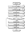
- FIG. 4 is a flowchart illustrating an example of a procedure of voltage measurement processing according to the first embodiment.
- FIG. 5 is a flowchart illustrating an example of the procedure of the voltage monitoring management process according to the first embodiment.
- FIG. 6 is a flowchart illustrating an example of a procedure of voltage value acquisition processing in the CPU unit.
- FIG. 7 is a diagram schematically showing an example of the configuration of the PLC system according to the second embodiment.
- FIG. 8 is a flowchart illustrating an example of a procedure of voltage monitoring management processing according to the second embodiment.
- FIG. 9 is a diagram schematically illustrating another example of the configuration of the PLC system.
- FIG. 10 is a diagram schematically illustrating another example of the configuration of the PLC system.
- FIG. 1 is a diagram schematically illustrating an example of a configuration of a PLC system according to the first embodiment.
- the PLC system 1 has a unit direct connection configuration and includes one basic block 10.
- the basic block 10 includes a power supply unit 11 that supplies power to each unit, a CPU unit 12 that manages the entire system, and target units 13-1 to 13-13 that are input / output units and other units having other functions. -4, and an end cover 14 that indicates the end of the block and is a termination unit that performs the termination process of the block. All the units (including the end cover 14) are connected by a bus (bus connector).
- the buses allow communication between the units, and a voltage is supplied from the power supply unit 11 to other units. In this example, the case where four target units 13-1 to 13-4 are arranged is shown, but the present invention is not limited to this.
- the CPU unit 12 includes a voltage monitoring unit 50 that monitors the voltage supplied to the CPU unit 12 and each unit (CPU unit) constituting the PLC system 1 (the basic block 10 in the first embodiment). 12, target units 13-1 to 13-4, and a voltage monitoring management unit 60 that manages the voltage supplied to the end cover 14).
- the display unit 70 attached to the CPU unit 12 the voltage value of the PLC system 1 can be monitored by the CPU unit 12 itself.
- the target units 13-1 to 13-4 and the end cover 14 include a voltage monitoring unit 50 that monitors the voltage supplied to the unit.
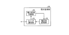
- FIG. 2 is a block diagram schematically showing a functional configuration of the voltage monitoring unit according to the first embodiment.
- the voltage monitoring unit 50 includes a unit communication unit 51, a voltage monitoring circuit unit 52, and a voltage value storage unit 53.
- the unit communication unit 51 has a function in which each unit communicates with another unit via a connector such as a bus connector.
- the voltage monitoring circuit unit 52 measures the voltage value supplied to each unit.
- the voltage value storage unit 53 stores the voltage value measured by the voltage monitoring circuit unit 52.
- FIG. 3 is a block diagram schematically illustrating a functional configuration of the voltage monitoring management unit according to the first embodiment.
- the voltage monitoring management unit 60 includes a CPU unit communication unit 61, a specified value storage unit 62, a comparison unit 63, and a comparison result storage unit 64.
- the CPU unit communication unit 61 communicates information with other units.
- the specified value storage unit 62 serves as a reference for determining whether or not the voltage supplied to the CPU unit 12 or other units (target units 13-1 to 13-4, end cover 14) is sufficient. Store the specified value.
- the comparison unit 63 compares the voltage value transmitted from another unit or from the voltage monitoring unit 50 of the CPU unit 12 with the specified value stored in the specified value storage unit 62, and compares the result. Write to the result storage unit 64. Further, when the voltage value is lower than the specified value, the comparison unit 63 reads the voltage value of the adjacent unit arranged (attached) on the power supply unit 11 side as compared with the unit currently being compared. Process.
- the comparison result storage unit 64 stores the result of the comparison between the voltage value of a certain unit and the specified value executed by the comparison unit 63.
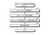
- FIG. 4 is a flowchart illustrating an example of a procedure of voltage measurement processing according to the first embodiment.
- the power supply unit 11 supplies a voltage to each unit via a connector such as a bus connector that connects the units (step S12).
- a connector such as a bus connector that connects the units
- the unit communication unit 51 can communicate.
- the voltage monitoring circuit unit 52 of the voltage monitoring unit 50 of each unit measures the voltage value supplied to the unit (step S13). Thereafter, the measured voltage value of the own unit is stored in the voltage value storage unit 53 (step S14). Thus, the voltage measurement process in each unit is completed.
- FIG. 5 is a flowchart showing an example of the procedure of the voltage monitoring management process according to the first embodiment.
- the power supply unit 11 supplies a voltage to each unit via a connector such as a bus connector that connects the units, and the system is activated.
- the CPU unit 12 performs processing for grasping the number of units connected to the directly connected PLC system 1 by bus access and the number of additional blocks (step S32).
- the CPU unit 12 acquires the unit arrangement state in the basic block 10 of the PLC system 1.
- a case where there is no additional block and only the basic block 10 is illustrated.
- the CPU unit 12 of the basic block 10 performs a voltage value acquisition process for obtaining the position of the unit at which the supplied voltage is less than the specified value through the bus connecting the units (step S33).
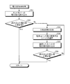
- FIG. 6 is a flowchart showing an example of the procedure of voltage value acquisition processing in the CPU unit.
- the CPU unit communication unit 61 of the voltage monitoring management unit 60 reads the voltage value of the voltage monitoring unit 50 incorporated in the end cover 14 through a bus connecting the units (step S51).
- the CPU unit 12 transmits a voltage value read request to the end cover 14, and the unit communication unit 51 of the end cover 14 sets the voltage value stored in the voltage value storage unit 53 as a response to the CPU. This is performed by a method such as transmission to the unit 12.
- the comparison unit 63 of the voltage monitoring management unit 60 has the read voltage value of the end cover 14 and the specified voltage value necessary for the operation of the PLC system 1 stored in the specified value storage unit 62.
- the specified value is compared (step S52). Specifically, it is determined whether the read voltage value is equal to or greater than a specified value.
- the comparison unit 63 stores the comparison result in the comparison result storage unit 64 (step S53). For example, the compared voltage value is stored in association with the end cover 14.
- the comparison unit 63 selects one unit disposed adjacent to the power supply unit 11 side of the end cover 14 (step S54), and the voltage value of the selected unit is obtained via the CPU unit communication unit 61. Read (step S55).
- the comparison unit 63 compares the read voltage value of the unit with the specified value stored in the specified value storage unit 62, and determines whether the read voltage value is greater than or equal to the specified value (step S56). .
- step S56 If the voltage value is greater than or equal to the specified value (Yes in step S56), or if the voltage value of the end cover 14 is greater than or equal to the specified value in step S52 (if Yes in step S52), the voltage value is acquired. Processing ends.
- step S56 If the voltage value is less than the specified value in step S56 (No in step S56), the process returns to step S53. Then, the processes in steps S53 to S56 are repeatedly executed until a unit is obtained in which the read voltage value is equal to or greater than the specified value.
- the comparison unit 63 associates the voltage value with the unit or the end cover 14 and stores the comparison result.
- the information is stored in the unit 64 (step S34).
- the comparison unit 63 performs a result display process for displaying the result stored in the comparison result storage unit 64 in the display unit 70 as a numerical value via the CPU unit communication unit 61 (step S35).
- the contents stored in the comparison result storage unit 64 are (1) when the voltage value of the end cover 14 is equal to or higher than the specified value, and (2) the voltage value of the end cover 14 is less than the specified value. In this case, two ways are conceivable.
- the display unit 70 performs a process of displaying that the voltage value of the end cover 14 is equal to or higher than a specified value.
- the comparison result storage unit 64 stores a unit (target unit 13-1) whose voltage value is equal to or higher than the specified value from the end cover 14. ⁇ 13-4 or CPU unit 12) are stored. Therefore, the display unit 70 displays that the voltage value of the unit whose voltage value is equal to or higher than the specified value is higher than the specified value, and the voltage value from the end cover 14 to the unit adjacent to the unit on the end cover 14 side To display that is less than the specified value.
- a schematic configuration diagram of the PLC system 1 as shown in FIG. 1 is drawn on the display unit 70, and the voltage value is displayed from the end cover 14 side therein. This can be done by displaying a voltage value or a specified value in addition to the voltage value up to the measured unit.
- a display method such as a bold display, a display with a changed color, a flashing display, or a display with a changed size is used to alert the user who views the display unit 70. May be displayed.
- the voltage monitoring management process ends.
- the CPU unit 12, the target units 13-1 to 13-4, and the end cover 14 of the basic block 10 of the PLC system 1 are provided with a voltage monitoring unit 50 that measures the voltage value supplied to the unit. It was. Further, the CPU unit 12 is compared with the voltage value measured by the end cover 14 and a specified voltage value required for the operation of the PLC system 1, and the measured voltage value is less than the specified voltage value. In this case, the voltage value acquisition process for comparing the voltage value measured by the unit adjacent to the power supply unit 11 side with the specified value is performed until a unit having the measured voltage value equal to or larger than the specified value appears, and the comparison is performed. The results were stored and displayed on the display unit 70. As a result, the voltage supplied to the unit itself can be monitored, and the user can easily understand the unit to which the voltage is sufficiently supplied and the unit to which the voltage is not supplied.
- the CPU unit 12 when the CPU unit 12 reads the voltage value of the end cover 14, if a value greater than the specified value is written in the voltage value storage unit 53 of the voltage monitoring unit 50, the voltage is sufficient in the route to the end cover 14. You can see that it is supplied. Further, when the CPU unit 12 reads the voltage value of the end cover 14, if a numerical value below the specified value is written in the voltage value storage unit 53 of the voltage monitoring unit 50, Read the voltage value. If the voltage value of the unit is equal to or higher than the specified value in the comparison unit 63 of the voltage monitoring management unit 60 of the CPU unit 12, it can be seen that a sufficient voltage is supplied from the power supply unit 11 to the unit.
- each unit when changing or adding a unit to be used, it can be seen whether the voltage value of each unit is supplied at a voltage higher than the specified value. I can understand. Furthermore, instead of displaying the voltage supply status in LED color, the voltage value and the specified value are displayed numerically for each unit, so it is necessary to know the voltage that is insufficient in each unit and to reduce the number of units. It becomes possible for the user to easily grasp whether there is any or how many units need to be changed. Furthermore, not only the end cover 14 but also each unit is equipped with a voltage monitoring unit 50, so that it can be seen that the voltage value of each unit is supplied at a voltage higher than a specified value. You can see if This also has an effect of reducing man-hours for system construction and maintenance.
- the voltage supply insufficiency occurs in each unit, it can be seen whether the voltage value of each unit is supplied at a voltage higher than the specified value. For example, when a system error occurs, the cause is voltage supply The user can quickly determine whether or not. As a result, the time for solving the cause of the system error can be shortened.
- Embodiment 2 FIG. In the first embodiment, the case where the PLC system is configured by only basic blocks is shown, but in the second embodiment, the case where the PLC system is configured by basic blocks and additional blocks is shown.
- FIG. 7 is a diagram schematically showing an example of the configuration of the PLC system according to the second embodiment.
- the PLC system 1 has one basic block 10 and an expansion block 20 connected to the basic block 10 via an expansion cable 30.
- the basic block 10 includes a power supply unit 11, a CPU unit 12, target units 13-1 to 13-3, an end cover 14, and a branch unit 15.
- the branch unit 15 is provided when a block other than the basic block 10 is added, and is provided at an arbitrary position between the CPU unit 12 and the end cover 14.
- the branch unit 15 includes the voltage monitoring unit 50 described in the first embodiment.
- the expansion block 20 serves as a connecting portion of the voltage supplied from the power supply unit 11 to the expansion block 20, and includes an expansion unit 21 as a start end, target units 22-1 to 22-4, an end cover 23 as a termination unit, Have
- the extension unit 21 includes the voltage monitoring unit 50 described in the first embodiment.
- the branch unit 15 of the basic block 10 and the extension unit 21 of the extension block 20 are connected by an extension cable 30. With this additional cable 30, it is possible to perform voltage supply and communication from the power supply unit 11 of the basic block 10. Note that the description of the same components as those in Embodiment 1 is omitted.
- FIG. 8 is a flowchart illustrating an example of a procedure of voltage monitoring management processing according to the second embodiment.
- the power supply unit 11 is connected to each unit (CPU unit 12, branch unit 15, target unit 13) of the basic block 10 via a connector such as a bus connector that connects the units. -1 to 13-3, the end cover 14), and each unit (extension unit 21, target units 22-1 to 22-) of the extension block 20 connected to the branch unit 15 via the extension cable 30. 4. Supply voltage to the end cover 23) to start the system.
- the CPU unit 12 performs processing for grasping the number of units connected to the directly connected PLC system 1 by bus access and the number of additional blocks (step S72).
- the comparison unit 63 of the voltage monitoring management unit 60 performs a voltage value acquisition process for obtaining the position of the unit at which the supplied voltage in the basic block 10 is less than the specified value through the bus connecting the units ( Step S73).
- this voltage value acquisition process the process shown in FIG.
- step S74 the comparison unit 63 associates the voltage value with the unit or the end cover 14 and stores it in the comparison result storage unit 64.
- the comparison unit 63 determines whether the expansion block 20 is connected to the basic block 10 (step S75). When the expansion block 20 is not connected to the basic block 10 (in the case of No in step S75), it is the same as in the first embodiment, and the comparison unit 63 is connected to the display unit 70 via the CPU unit communication unit 61. A result display process for displaying the result stored in the comparison result storage unit 64 is performed (step S78).
- step S75 when the extension block 20 is connected to the basic block 10 (Yes in step S75), the comparison unit 63 connects the bus connecting the units and the extension cable 30 connecting the blocks. Then, a voltage value acquisition process is performed to determine the position of the unit at which the supplied voltage in the expansion block 20 is less than the specified value (step S76). In this voltage value acquisition process, the process shown in FIG.
- the comparison unit 63 compares the voltage value with the unit or the end cover 14 for comparison.
- the result is stored in the result storage unit 64 (step S77).
- the comparison unit 63 performs a result display process for displaying the result stored in the comparison result storage unit 64 on the display unit 70 via the CPU unit communication unit 61 (step S78). This display can be performed in the same manner as in the first embodiment.
- the voltage monitoring management process ends.
- FIG. 7 shows the case where one extension block 20 is connected to the basic block 10
- two or more extension blocks may be connected.
- a branch unit is provided in the extension block 20
- an extension unit is provided in the new extension block
- an extension cable is connected between the branch unit of the extension block 20 and the extension unit of the new extension block.
- an end cover 23 is provided at each end of the extension block 20 and the new extension block.
- the number of target units 13-1 to 13-3 and 22-1 to 22-4 in the basic block 10 and the extension block 20 in FIG. 7 is an example, and the present invention is not limited to this.
- the voltage monitoring unit 50 is provided in each unit, and the voltage value measured by the voltage monitoring unit 50 is used as the CPU unit 12. Was to get.
- the user can visually recognize a unit to which a sufficient voltage is supplied and a unit to which no voltage is supplied.
- the cable connected from the branch unit 15 to the extension unit 21 can determine whether or not there is insufficient voltage supply due to a voltage drop.
- each unit is equipped with a voltage monitoring unit 50, and it can be seen that the voltage value of each unit is supplied at a voltage higher than a specified value.
- a voltage monitoring unit 50 it is possible to easily grasp whether a voltage supply shortage has occurred. This can lead to reduction in man-hours for system construction and maintenance.
- each unit measures the voltage value when the PLC system 1 is started up, and the voltage monitoring management unit 60 of the CPU unit 12 reads and displays the result is shown.
- the present invention is not limited to this.
- the voltage value measurement and the result display of each unit can be executed at an arbitrary timing.
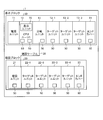
- FIG. 9 is a diagram schematically illustrating another example of the configuration of the PLC system.
- This PLC system 1 has a CPU unit 12 with a built-in display monitor 121 (display function). In the CPU unit 12, the acquired voltage value and the specified value are displayed on the display monitor 121.
- FIG. 10 is a diagram schematically showing another example of the configuration of the PLC system.
- the CPU unit 12 is not provided with the display unit 70 or the display monitor 121, and the voltage value is displayed by a unit other than the CPU unit 12. In this case, the voltage value and the specified value are displayed on the display device 40 connected from the CPU unit 12 via the cable 41.
- the comparison result storage unit 64 stores the voltage value of each block as the comparison result, and the display unit (in the case of FIG. 7, the display unit 70, in the case of FIG. 9, the display monitor). 121, which is the display device 40 in the case of FIG. 10), the voltage value of each block can be displayed.
- the PLC system according to the present invention is useful for a unit direct connection type PLC system.
- 1 PLC system 10 basic block, 11 power supply unit, 12 CPU unit, 13-1 to 13-4, 22-1 to 22-4 target unit, 14, 23 end cover, 15 branch unit, 20 extension block, 21 extension Unit, 30 extension cable, 40 display device, 41 cable, 50 voltage monitoring unit, 51 unit communication unit, 52 voltage monitoring circuit unit, 53 voltage value storage unit, 60 voltage monitoring management unit, 61 CPU unit communication unit, 62 specified value Storage unit, 63 comparison unit, 64 comparison result storage unit, 70 display unit, 121 display monitor.
Landscapes
- Engineering & Computer Science (AREA)
- Physics & Mathematics (AREA)
- General Physics & Mathematics (AREA)
- Theoretical Computer Science (AREA)
- Automation & Control Theory (AREA)
- General Engineering & Computer Science (AREA)
- Programmable Controllers (AREA)
Abstract
Description
図1は、実施の形態1によるPLCシステムの構成の一例を模式的に示す図である。PLCシステム1は、ユニット直接連結型の構成を有しており、1つの基本ブロック10を含む。基本ブロック10は、各ユニットに対して電源を供給する電源ユニット11と、システム全体を管理するCPUユニット12と、入出力ユニットや他の機能を有する他のユニットであるターゲットユニット13-1~13-4と、ブロックの終端を示し、ブロックの終端処理を行う終端ユニットであるエンドカバー14と、を有する。全てのユニット(エンドカバー14も含む)は、バス(バスコネクタ)で接続されている。このバスによって、各ユニット間で通信ができるとともに、電源ユニット11から他のユニットに対して電圧が供給される。また、この例では、ターゲットユニット13-1~13-4が4個配置されている場合が示されているが、これに限定されるものではない。
この場合には、比較結果記憶部64には、エンドカバー14の電圧値のみが記憶されている。そのため、表示ユニット70は、エンドカバー14の電圧値が規定値以上であることを表示する処理を行う。
この場合には、比較結果記憶部64には、エンドカバー14から、電圧値が規定値以上となったユニット(ターゲットユニット13-1~13-4またはCPUユニット12)までの電圧値が記憶されている。そのため、表示ユニット70は、電圧値が規定値以上となったユニットの電圧値は規定値以上であることを表示し、エンドカバー14からそのユニットにエンドカバー14側に隣接するユニットまでの電圧値が規定値未満であることを表示する処理を行う。
実施の形態1では、PLCシステムが基本ブロックのみで構成される場合を示したが、実施の形態2では、PLCシステムが基本ブロックと増設ブロックとによって構成される場合を示す。
Claims (6)
- 電源ユニットと、CPUユニットと、前記電源ユニットに対して終端に配置される第1終端ユニットと、前記電源ユニットと前記第1終端ユニットとの間に配置される他のユニットと、がコネクタを介して接続される基本ブロックを備えるPLCシステムにおいて、
前記他のユニットと前記第1終端ユニットは、自ユニットに供給される電圧値を測定し、記憶する電圧測定部を備え、
前記CPUユニットは、
自ユニットに供給される電圧値を測定し、記憶する電圧測定部と、
前記第1終端ユニット、前記他のユニットまたは自ユニットの前記電圧測定部に記憶されている前記電圧値を読込み、前記電圧値が当該PLCシステムを構成する各ユニットを駆動するのに必要な規定値以上であるかを判定する電圧値取得処理を行い、前記電圧値取得処理の結果を数値で表示部に表示する電圧監視管理部と、
を備え、
前記電圧監視管理部は、前記第1終端ユニットの前記電圧値取得処理を行い、前記第1終端ユニットの電圧値が前記規定値よりも低い場合に、前記第1終端ユニットから前記電源ユニット側に向かって前記電圧値が前記規定値以上となるユニットが見つかるまで前記電圧値取得処理を実行することを特徴とするPLCシステム。 - 前記基本ブロックに第1増設ケーブルを介して電気的に接続される第1増設ブロックをさらに備え、
前記基本ブロックは、前記電源ユニットと前記第1終端ユニットとの間に配置される第1分岐ユニットをさらに備え、
前記第1増設ブロックは、前記基本ブロックの前記第1分岐ユニットと前記第1増設ケーブルを介して接続される第1増設ユニットと、前記第1増設ユニットに対して終端に配置される第2終端ユニットと、前記第1増設ユニットと前記第2終端ユニットとの間に配置される他のユニットと、がコネクタを介して接続され、
前記電圧監視管理部は、前記第2終端ユニットの前記電圧値取得処理を行い、前記第2終端ユニットの電圧値が前記規定値よりも低い場合に、前記第2終端ユニットから前記第1増設ユニット側に向かって前記電圧値が前記規定値以上となるユニットが見つかるまで前記電圧値取得処理を実行する機能をさらに有することを特徴とする請求項1に記載のPLCシステム。 - 前記第1増設ブロックに第2増設ケーブルを介して電気的に接続される第2増設ブロックをさらに備え、
前記第1増設ブロックは、第2分岐ユニットをさらに備え、
前記第2増設ブロックは、前記第1増設ブロックの前記第2分岐ユニットと前記第2増設ケーブルを介して接続される第2増設ユニットと、前記第2増設ユニットに対して終端に配置される第3終端ユニットと、前記第2増設ユニットと前記第3終端ユニットとの間に配置される他のユニットと、がコネクタを介して接続され、
前記電圧監視管理部は、前記第3終端ユニットの前記電圧値取得処理を行い、前記第3終端ユニットの電圧値が前記規定値よりも低い場合に、前記第3終端ユニットから前記第2増設ユニット側に向かって前記電圧値が前記規定値以上となるユニットが見つかるまで前記電圧値取得処理を実行する機能をさらに有することを特徴とする請求項2に記載のPLCシステム。 - 前記電圧測定部は、当該PLCシステムの電源がオンにされたときに、各ユニットに供給される電圧値の測定処理を行い、
前記電圧監視管理部は、当該PLCシステムの電源がオンにされたときに、前記電圧値取得処理を行うことを特徴とする請求項1に記載のPLCシステム。 - 前記電圧測定部は、任意のタイミングで各ユニットに供給される電圧値の測定処理を行い、
前記電圧監視管理部は、任意のタイミングで前記電圧値取得処理を行うことを特徴とする請求項1に記載のPLCシステム。 - 前記表示部は、前記CPUユニットに装着された表示ユニット、前記CPUユニットに内蔵された表示装置、または前記CPUユニットにケーブルを介して接続された表示装置であることを特徴とする請求項1から5のいずれか1つに記載のPLCシステム。
Priority Applications (7)
| Application Number | Priority Date | Filing Date | Title |
|---|---|---|---|
| JP2015507887A JP5819023B2 (ja) | 2013-03-29 | 2013-03-29 | Plcシステム |
| US14/780,599 US20160041544A1 (en) | 2013-03-29 | 2013-03-29 | Plc system |
| KR1020157030357A KR101625813B1 (ko) | 2013-03-29 | 2013-03-29 | Plc 시스템 |
| CN201380075242.0A CN105074593B (zh) | 2013-03-29 | 2013-03-29 | Plc系统 |
| EP13880017.2A EP2980663B1 (en) | 2013-03-29 | 2013-03-29 | Plc system |
| PCT/JP2013/059606 WO2014155697A1 (ja) | 2013-03-29 | 2013-03-29 | Plcシステム |
| TW102135290A TWI489231B (zh) | 2013-03-29 | 2013-09-30 | Plc系統 |
Applications Claiming Priority (1)
| Application Number | Priority Date | Filing Date | Title |
|---|---|---|---|
| PCT/JP2013/059606 WO2014155697A1 (ja) | 2013-03-29 | 2013-03-29 | Plcシステム |
Publications (1)
| Publication Number | Publication Date |
|---|---|
| WO2014155697A1 true WO2014155697A1 (ja) | 2014-10-02 |
Family
ID=51622749
Family Applications (1)
| Application Number | Title | Priority Date | Filing Date |
|---|---|---|---|
| PCT/JP2013/059606 Ceased WO2014155697A1 (ja) | 2013-03-29 | 2013-03-29 | Plcシステム |
Country Status (7)
| Country | Link |
|---|---|
| US (1) | US20160041544A1 (ja) |
| EP (1) | EP2980663B1 (ja) |
| JP (1) | JP5819023B2 (ja) |
| KR (1) | KR101625813B1 (ja) |
| CN (1) | CN105074593B (ja) |
| TW (1) | TWI489231B (ja) |
| WO (1) | WO2014155697A1 (ja) |
Cited By (4)
| Publication number | Priority date | Publication date | Assignee | Title |
|---|---|---|---|---|
| CN107003652A (zh) * | 2014-12-03 | 2017-08-01 | 三菱电机株式会社 | 可编程逻辑控制器系统 |
| EP3311275A4 (en) * | 2015-06-17 | 2018-12-26 | ABB Schweiz AG | Control system with error detection |
| JP2019032780A (ja) * | 2017-08-09 | 2019-02-28 | 富士電機株式会社 | 制御装置、制御システム、方法及びプログラム |
| WO2022153559A1 (ja) * | 2021-01-18 | 2022-07-21 | オムロン株式会社 | Ioユニットおよびエンドユニット |
Citations (6)
| Publication number | Priority date | Publication date | Assignee | Title |
|---|---|---|---|---|
| JPS63116207A (ja) * | 1986-11-04 | 1988-05-20 | Omron Tateisi Electronics Co | プログラマブル・コントロ−ラ |
| JPH01172103U (ja) * | 1988-05-20 | 1989-12-06 | ||
| JPH0887307A (ja) * | 1994-09-20 | 1996-04-02 | Hitachi Ltd | プログラマブルコントローラ |
| JP2002108417A (ja) | 2000-09-29 | 2002-04-10 | Keyence Corp | 増設型plcシステム及びこれに組み込まれる発信ユニット、受信ユニット並びにエンドユニット |
| JP2011242983A (ja) * | 2010-05-18 | 2011-12-01 | Mitsubishi Electric Corp | プログラマブルコントローラシステム |
| JP2012043237A (ja) * | 2010-08-20 | 2012-03-01 | Koyo Electronics Ind Co Ltd | Plcの電源制御方式 |
Family Cites Families (13)
| Publication number | Priority date | Publication date | Assignee | Title |
|---|---|---|---|---|
| US6892265B2 (en) * | 2001-02-14 | 2005-05-10 | Berkley Process Control, Inc. | Configurable connectorized I/O system |
| KR100582215B1 (ko) * | 2003-12-31 | 2006-05-23 | 주식회사 우림데이시스 | 전자식 전력량계를 구현한 다기능 전력선통신(plc) 모듈 |
| US7287429B2 (en) * | 2004-03-25 | 2007-10-30 | Denso Corporation | Capacitive acceleration sensor system |
| JP4893931B2 (ja) | 2006-05-19 | 2012-03-07 | オムロン株式会社 | セーフティ・コントローラ |
| JP4784759B2 (ja) | 2006-10-16 | 2011-10-05 | オムロン株式会社 | Plc装置 |
| US7791856B2 (en) * | 2007-02-09 | 2010-09-07 | Ephaugh, Inc. | Method and apparatus for moving material |
| FR2917922B1 (fr) * | 2007-06-25 | 2009-07-31 | Schneider Electric Ind Sas | Communication par courant porteur pour les tableaux centralises de commande |
| US8702306B2 (en) * | 2007-09-21 | 2014-04-22 | Siemens Industry, Inc. | Systems, devices, and/or methods for managing a thermocouple module |
| CN102033502B (zh) * | 2009-09-25 | 2014-04-02 | 松下神视株式会社 | 可编程控制器 |
| DE102009054155A1 (de) * | 2009-11-23 | 2011-05-26 | Abb Ag | Ein- und/oder Ausgabe-Sicherheitsmodul für ein Automatisierungsgerät |
| CN202075585U (zh) * | 2011-01-28 | 2011-12-14 | 库博标准荆大(荆州)汽车配件有限公司 | 双层卷焊管生产线plc控制柜 |
| CN103403635B (zh) * | 2011-03-04 | 2015-11-25 | 株式会社安川电机 | 控制装置 |
| CN202121311U (zh) * | 2011-06-29 | 2012-01-18 | 淄博职业学院 | Plc控制检测线路保护系统 |
-
2013
- 2013-03-29 JP JP2015507887A patent/JP5819023B2/ja not_active Expired - Fee Related
- 2013-03-29 EP EP13880017.2A patent/EP2980663B1/en not_active Not-in-force
- 2013-03-29 KR KR1020157030357A patent/KR101625813B1/ko not_active Expired - Fee Related
- 2013-03-29 CN CN201380075242.0A patent/CN105074593B/zh not_active Expired - Fee Related
- 2013-03-29 US US14/780,599 patent/US20160041544A1/en not_active Abandoned
- 2013-03-29 WO PCT/JP2013/059606 patent/WO2014155697A1/ja not_active Ceased
- 2013-09-30 TW TW102135290A patent/TWI489231B/zh not_active IP Right Cessation
Patent Citations (6)
| Publication number | Priority date | Publication date | Assignee | Title |
|---|---|---|---|---|
| JPS63116207A (ja) * | 1986-11-04 | 1988-05-20 | Omron Tateisi Electronics Co | プログラマブル・コントロ−ラ |
| JPH01172103U (ja) * | 1988-05-20 | 1989-12-06 | ||
| JPH0887307A (ja) * | 1994-09-20 | 1996-04-02 | Hitachi Ltd | プログラマブルコントローラ |
| JP2002108417A (ja) | 2000-09-29 | 2002-04-10 | Keyence Corp | 増設型plcシステム及びこれに組み込まれる発信ユニット、受信ユニット並びにエンドユニット |
| JP2011242983A (ja) * | 2010-05-18 | 2011-12-01 | Mitsubishi Electric Corp | プログラマブルコントローラシステム |
| JP2012043237A (ja) * | 2010-08-20 | 2012-03-01 | Koyo Electronics Ind Co Ltd | Plcの電源制御方式 |
Cited By (5)
| Publication number | Priority date | Publication date | Assignee | Title |
|---|---|---|---|---|
| CN107003652A (zh) * | 2014-12-03 | 2017-08-01 | 三菱电机株式会社 | 可编程逻辑控制器系统 |
| EP3311275A4 (en) * | 2015-06-17 | 2018-12-26 | ABB Schweiz AG | Control system with error detection |
| JP2019032780A (ja) * | 2017-08-09 | 2019-02-28 | 富士電機株式会社 | 制御装置、制御システム、方法及びプログラム |
| WO2022153559A1 (ja) * | 2021-01-18 | 2022-07-21 | オムロン株式会社 | Ioユニットおよびエンドユニット |
| JP7639353B2 (ja) | 2021-01-18 | 2025-03-05 | オムロン株式会社 | Ioユニットおよびエンドユニット |
Also Published As
| Publication number | Publication date |
|---|---|
| EP2980663A1 (en) | 2016-02-03 |
| EP2980663A4 (en) | 2016-12-28 |
| CN105074593A (zh) | 2015-11-18 |
| JP5819023B2 (ja) | 2015-11-18 |
| JPWO2014155697A1 (ja) | 2017-02-16 |
| TWI489231B (zh) | 2015-06-21 |
| KR101625813B1 (ko) | 2016-05-30 |
| KR20150123349A (ko) | 2015-11-03 |
| CN105074593B (zh) | 2017-08-25 |
| TW201437775A (zh) | 2014-10-01 |
| EP2980663B1 (en) | 2017-08-23 |
| US20160041544A1 (en) | 2016-02-11 |
Similar Documents
| Publication | Publication Date | Title |
|---|---|---|
| US10296278B2 (en) | Power distribution apparatus having capability for color management | |
| JP5346726B2 (ja) | 連設型センサシステム、ネットワークユニット、及びセンサユニット | |
| JP5819023B2 (ja) | Plcシステム | |
| US20150316600A1 (en) | Portable multi-function cable tester | |
| EP3746851B1 (en) | Method and apparatus for configuring i/o modules connected to a fieldbus controller | |
| US20190049508A1 (en) | PORTABLE MULTl-FUNCTION CABLE TESTER | |
| CN104679116B (zh) | 服务器机柜系统、电路板组合系统及其电路板 | |
| KR101527129B1 (ko) | 다심선 구별 테스터 | |
| JP6042585B2 (ja) | 制御・監視信号伝送システムの新品子局設定方式 | |
| JP2015135634A (ja) | 入出力ユニット | |
| JP3183952U (ja) | 状態表示器付きコネクタ/端子台変換アダプタ | |
| JPWO2018078773A1 (ja) | 信号表示灯システムおよびそのための信号表示灯 | |
| TW201913120A (zh) | 電纜線自動測試裝置 | |
| KR20200125084A (ko) | 식별 기능을 구비한 네트워크 시스템 | |
| WO2014065006A1 (ja) | 充電器電池容量表示装置 | |
| JP2020058198A (ja) | 管理装置 | |
| JP6926703B2 (ja) | 電力量管理システム、電力量モニタ認識プログラム及び記録媒体 | |
| JP2013073625A (ja) | ネットワーク状態の表示システム及びこれを備えたマウス | |
| TWI501079B (zh) | 伺服器機櫃系統、電路板組合系統及其電路板 | |
| JP2020056744A (ja) | スマートタップ | |
| KR102383850B1 (ko) | 네트워크 관리장치 및 이를 구비하는 네트워크 통신 시스템 | |
| KR200465255Y1 (ko) | 전압 측정 및 표시가 가능한 라우터 | |
| JP3184775U (ja) | 警報センサシステム | |
| CN114527681A (zh) | 智能料架的管理电路 | |
| JPWO2021084616A1 (ja) | 通信システム |
Legal Events
| Date | Code | Title | Description |
|---|---|---|---|
| WWE | Wipo information: entry into national phase |
Ref document number: 201380075242.0 Country of ref document: CN |
|
| 121 | Ep: the epo has been informed by wipo that ep was designated in this application |
Ref document number: 13880017 Country of ref document: EP Kind code of ref document: A1 |
|
| ENP | Entry into the national phase |
Ref document number: 2015507887 Country of ref document: JP Kind code of ref document: A |
|
| REEP | Request for entry into the european phase |
Ref document number: 2013880017 Country of ref document: EP |
|
| WWE | Wipo information: entry into national phase |
Ref document number: 2013880017 Country of ref document: EP |
|
| WWE | Wipo information: entry into national phase |
Ref document number: 14780599 Country of ref document: US |
|
| NENP | Non-entry into the national phase |
Ref country code: DE |
|
| ENP | Entry into the national phase |
Ref document number: 20157030357 Country of ref document: KR Kind code of ref document: A |