WO2014155782A1 - 画像処理装置、内視鏡装置、プログラム及び画像処理方法 - Google Patents
画像処理装置、内視鏡装置、プログラム及び画像処理方法 Download PDFInfo
- Publication number
- WO2014155782A1 WO2014155782A1 PCT/JP2013/075869 JP2013075869W WO2014155782A1 WO 2014155782 A1 WO2014155782 A1 WO 2014155782A1 JP 2013075869 W JP2013075869 W JP 2013075869W WO 2014155782 A1 WO2014155782 A1 WO 2014155782A1
- Authority
- WO
- WIPO (PCT)
- Prior art keywords
- classification
- unit
- focus
- subject
- pixel
- Prior art date
- Legal status (The legal status is an assumption and is not a legal conclusion. Google has not performed a legal analysis and makes no representation as to the accuracy of the status listed.)
- Ceased
Links
Images









Classifications
-
- A—HUMAN NECESSITIES
- A61—MEDICAL OR VETERINARY SCIENCE; HYGIENE
- A61B—DIAGNOSIS; SURGERY; IDENTIFICATION
- A61B1/00—Instruments for performing medical examinations of the interior of cavities or tubes of the body by visual or photographical inspection, e.g. endoscopes; Illuminating arrangements therefor
- A61B1/00002—Operational features of endoscopes
- A61B1/00004—Operational features of endoscopes characterised by electronic signal processing
- A61B1/00009—Operational features of endoscopes characterised by electronic signal processing of image signals during a use of endoscope
- A61B1/000095—Operational features of endoscopes characterised by electronic signal processing of image signals during a use of endoscope for image enhancement
-
- A—HUMAN NECESSITIES
- A61—MEDICAL OR VETERINARY SCIENCE; HYGIENE
- A61B—DIAGNOSIS; SURGERY; IDENTIFICATION
- A61B1/00—Instruments for performing medical examinations of the interior of cavities or tubes of the body by visual or photographical inspection, e.g. endoscopes; Illuminating arrangements therefor
- A61B1/00163—Optical arrangements
- A61B1/00188—Optical arrangements with focusing or zooming features
-
- A—HUMAN NECESSITIES
- A61—MEDICAL OR VETERINARY SCIENCE; HYGIENE
- A61B—DIAGNOSIS; SURGERY; IDENTIFICATION
- A61B1/00—Instruments for performing medical examinations of the interior of cavities or tubes of the body by visual or photographical inspection, e.g. endoscopes; Illuminating arrangements therefor
- A61B1/04—Instruments for performing medical examinations of the interior of cavities or tubes of the body by visual or photographical inspection, e.g. endoscopes; Illuminating arrangements therefor combined with photographic or television appliances
- A61B1/05—Instruments for performing medical examinations of the interior of cavities or tubes of the body by visual or photographical inspection, e.g. endoscopes; Illuminating arrangements therefor combined with photographic or television appliances characterised by the image sensor, e.g. camera, being in the distal end portion
-
- G—PHYSICS
- G02—OPTICS
- G02B—OPTICAL ELEMENTS, SYSTEMS OR APPARATUS
- G02B23/00—Telescopes, e.g. binoculars; Periscopes; Instruments for viewing the inside of hollow bodies; Viewfinders; Optical aiming or sighting devices
- G02B23/24—Instruments or systems for viewing the inside of hollow bodies, e.g. fibrescopes
- G02B23/2476—Non-optical details, e.g. housings, mountings, supports
- G02B23/2484—Arrangements in relation to a camera or imaging device
-
- G—PHYSICS
- G06—COMPUTING OR CALCULATING; COUNTING
- G06F—ELECTRIC DIGITAL DATA PROCESSING
- G06F18/00—Pattern recognition
- G06F18/20—Analysing
- G06F18/24—Classification techniques
-
- G—PHYSICS
- G06—COMPUTING OR CALCULATING; COUNTING
- G06T—IMAGE DATA PROCESSING OR GENERATION, IN GENERAL
- G06T7/00—Image analysis
- G06T7/0002—Inspection of images, e.g. flaw detection
- G06T7/0012—Biomedical image inspection
-
- G—PHYSICS
- G06—COMPUTING OR CALCULATING; COUNTING
- G06T—IMAGE DATA PROCESSING OR GENERATION, IN GENERAL
- G06T7/00—Image analysis
- G06T7/50—Depth or shape recovery
-
- G—PHYSICS
- G06—COMPUTING OR CALCULATING; COUNTING
- G06T—IMAGE DATA PROCESSING OR GENERATION, IN GENERAL
- G06T7/00—Image analysis
- G06T7/60—Analysis of geometric attributes
-
- G—PHYSICS
- G06—COMPUTING OR CALCULATING; COUNTING
- G06V—IMAGE OR VIDEO RECOGNITION OR UNDERSTANDING
- G06V20/00—Scenes; Scene-specific elements
- G06V20/60—Type of objects
- G06V20/69—Microscopic objects, e.g. biological cells or cellular parts
- G06V20/698—Matching; Classification
-
- G—PHYSICS
- G06—COMPUTING OR CALCULATING; COUNTING
- G06T—IMAGE DATA PROCESSING OR GENERATION, IN GENERAL
- G06T2207/00—Indexing scheme for image analysis or image enhancement
- G06T2207/10—Image acquisition modality
- G06T2207/10068—Endoscopic image
Definitions
- the present invention relates to an image processing device, an endoscope device, a program, an image processing method, and the like.
- a magnifying endoscope having a magnifying optical system
- Some of these magnifying endoscopes have a magnification of several tens to several hundreds, and the fine structure of the mucosal surface layer can be observed by using in combination with contrast enhancement by pigment dispersion. It is known that there is a difference in these patterns between the lesioned part and the normal part, which is one criterion for lesion diagnosis.
- Patent Document 1 discloses a technique in which the luminance level of a pixel of interest in a local extraction region is compared with the luminance level of surrounding pixels, and coloring is performed when the region of interest is darker than the peripheral region. This method is based on the assumption that when the distance is long, the image is darkly captured because the amount of reflected light reflected from the living body surface is small.
- Patent Literature 2 discloses a method of performing classification and categorization by grid division and feature amount extraction on an image obtained by imaging a specimen tissue, and displaying different modes for each classification.
- the pit pattern on the image is classified by matching processing with a known pit pattern shape and the image, and the classification result is A display method is conceivable. In the out-of-focus area on the image, the pit pattern cannot be detected by the matching process even in the place where the pit pattern actually exists, resulting in an incorrect classification result, and the display reliability is lowered.
- an image processing device an endoscope device, a program, an image processing method, and the like that can improve the reliability of highlighting.
- One aspect of the present invention is an image acquisition unit that acquires a captured image including an image of a subject, a distance information acquisition unit that acquires distance information based on a distance from the imaging unit to the subject at the time of imaging, and the distance information
- a focus determination unit that determines whether or not the subject is in focus in the pixel or region of the captured image, and performs classification processing of the structure of the subject, and the pixel or region in the pixel or region
- the present invention relates to an image processing apparatus including a classification unit that controls a target of the classification process according to a determination result, and an enhancement processing unit that performs an enhancement process on the captured image based on the result of the classification process.
- a subject structure classification process is performed, and the target of the classification process is controlled according to a determination result of whether or not the subject is in focus in a pixel or a region of a captured image.
- the enhancement process is performed based on the result of the classification process.
- Another aspect of the present invention relates to an endoscope apparatus including the image processing apparatus described above.
- a captured image including an image of a subject is acquired, distance information based on a distance from the imaging unit at the time of imaging to the subject is acquired, and the imaging is performed based on the distance information. It is determined whether or not the subject is in focus in a pixel or area of the image, the structure of the subject is classified, and the classification process is performed according to the determination result in the pixel or the area And a program that causes a computer to execute a step of performing enhancement processing of the captured image based on the result of the classification processing.
- a captured image including an image of a subject is acquired, distance information based on a distance from the imaging unit at the time of imaging to the subject is acquired, and the imaging is performed based on the distance information. It is determined whether or not the subject is in focus in a pixel or area of the image, the structure of the subject is classified, and the classification process is performed according to the determination result in the pixel or the area And an image processing method for performing enhancement processing of the captured image based on the result of the classification processing.
- FIG. 1A is a diagram illustrating a relationship between an imaging unit and a subject when an abnormal part is observed.
- FIG. 1B shows an example of an acquired image.
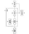
- FIG. 2 is a configuration example of an image processing apparatus.
- FIG. 3 is a configuration example of the endoscope apparatus according to the first embodiment.
- FIG. 4 is a configuration example of an external I / F unit according to the first embodiment.
- FIG. 5 is a diagram illustrating a change in the depth of field of the imaging system with respect to the operation of the zoom lever.
- FIG. 6 is a detailed configuration example of the image processing unit.
- FIG. 7 is a detailed configuration example of a focus determination unit in the first embodiment.
- FIG. 8 is an explanatory diagram of the classification process.
- FIG. 1A is a diagram illustrating a relationship between an imaging unit and a subject when an abnormal part is observed.
- FIG. 1B shows an example of an acquired image.
- FIG. 2 is a configuration example of an image processing apparatus.
- FIG. 9 is a configuration example of an endoscope apparatus according to the second embodiment.
- FIG. 10 is a configuration example of an external I / F unit in the second embodiment.
- FIG. 11 is a detailed configuration example of the focus control unit.
- FIG. 12 is a detailed configuration example of an in-focus determination unit according to the second embodiment.
- FIG. 13 is an explanatory diagram for classification processing in the second embodiment.
- FIG. 14 is a detailed configuration example of the classification unit.
- FIG. 15A and FIG. 15B are explanatory diagrams of processing performed by the surface shape calculation unit.
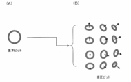
- FIG. 16A shows an example of a basic pit.
- FIG. 16B shows an example of a corrected pit.
- FIG. 17 is a detailed configuration example of the surface shape calculation unit.
- FIG. 16A shows an example of a basic pit.
- FIG. 16B shows an example of a corrected pit.
- FIG. 17 is a detailed configuration example of the surface shape calculation unit.
- FIG. 16A shows an example of a
- FIGS. 19A to 19F are explanatory diagrams of specific examples of classification processing.
- FIG. 20 is a detailed configuration example of a classification processing unit in the second classification processing method.
- FIG. 21 shows an example of classification types when a plurality of classification types are used. 22A to 22F show examples of pit patterns.
- FIG. 1A shows the relationship between the imaging unit 200 and the subject when observing an abnormal part (for example, an early lesion).
- FIG. 1B shows an example of an image acquired at that time.
- the normal gland duct 40 shows a normal pit pattern
- the abnormal gland duct 50 shows an abnormal pit pattern having an irregular shape
- the gland duct disappearing area 60 shows an abnormal area where the pit pattern has disappeared due to a lesion.
- FIG. 1A when an operator discovers an abnormal part (abnormal gland duct 50, gland duct disappearing region 60), the imaging part 200 is brought close to the abnormal part, and the imaging part 200 and the abnormal part are made as positive as possible. Make it counter.
- FIG. 1B regular structures are arranged in a uniform arrangement in the pit pattern of the normal part (normal gland duct 40).
- a normal pit pattern structure is registered or learned in advance as known characteristic information (foreseeing information), and the normal part is detected by matching processing or the like.
- an abnormal portion where the pit pattern has an irregular shape or disappears for example, an area where a normal pit pattern is not detected is regarded as an abnormal portion and is classified.
- misclassification may occur in an area where the amount of image information is small.
- the depth of field DA becomes very shallow (for example, several millimeters). Therefore, as shown in FIG. 1B, an out-of-focus region RB is likely to occur in the image. In such a region RB, since the accuracy of the matching process is lowered, even a region that should originally be classified as a normal part may be erroneously classified as an abnormal part and displayed as an abnormal part.
- the image processing apparatus includes an image acquisition unit 305 that acquires a captured image including an image of the subject, and distance information based on the distance from the imaging unit 200 to the subject at the time of imaging.
- a distance information acquisition unit 340 to be acquired a focus determination unit 370 that determines whether or not the subject is in focus in the pixel or region of the captured image based on the distance information, and a structure classification process of the subject
- a classification unit 310 that controls the target of the classification process according to the determination result in the pixel or region, and an enhancement processing unit 330 that performs the enhancement process of the captured image based on the result of the classification process.
- the pixel or the region determined to be out of focus is excluded from the target of the matching process, and is classified into “unknown” indicating that the classification of the pit pattern is unknown.
- matching processing is performed regardless of the result of the focus determination, and the pixel or region determined to be out of focus is reclassified as “unknown”.
- the distance information is information in which each position of the captured image is associated with the distance to the subject at each position.
- the distance in the optical axis direction of the imaging unit 200 is associated with each pixel. It is a distance map.
- the distance information is not limited to the distance map, and may be various information acquired based on the distance from the imaging unit 200 to the subject.
- the classification process is not limited to the pit pattern classification process, and may be any process that classifies the structure of the subject according to, for example, the type or state.
- the structure can assist the user's observation and diagnosis by presenting the classification result to the user.
- the polyp generated in the mucous membrane is not limited to the pit pattern.
- lesions such as gastrointestinal fistula, blood vessels, and cancer may be used.
- classification is made according to the type, the state of normal / abnormal, or the degree of abnormality.
- classification processes can be assumed as specific classification processes.
- the shape of the subject surface is obtained from the distance information, the reference pit pattern deformed according to the shape is matched with the image, and the pit pattern on the image is classified based on the matching result. May be.
- the pit patterns may be classified by matching the reference pit pattern and the image with, for example, POC (PhasePOOnly Correlation) without performing deformation using the distance information.
- the subject may be classified by extracting a specific structure such as a polyp or a groove.
- a specific structure such as a polyp or a groove.
- the stereo image is stereo-matched to obtain a distance map, and the low-pass filter process, the morphological process, and the like are performed on the distance map to obtain information on the general shape of the subject.
- the local shape information is obtained by subtracting the global shape information from the distance map.
- the known characteristic information of the structure to be classified (for example, the size and shape of a specific polyp, or the depth and width of a lesion-specific groove, etc.) is compared with the information of the local uneven structure, and the known characteristic information Extract the concavo-convex structure that matches In this way, specific structures such as polyps and grooves can be classified.
- the enhancement process is a process for conspicuous or identifying a specific target on the image.
- it may be a process for structure enhancement or color enhancement for an area classified into a specific type or state, or a process for highlighting the area, a process for surrounding the area with a line, or the area. It may be a process of attaching a mark indicating.
- the specific area may be made conspicuous (or identified) by performing the above-described processing on an area other than the specific area.
- FIG. 3 shows a configuration example of the endoscope device according to the first embodiment.
- the endoscope apparatus includes a light source unit 100, an imaging unit 200, a processor unit 300 (control device), a display unit 400, and an external I / F unit 500.
- the light source unit 100 includes a white light source 101, a rotating color filter 102 having a plurality of spectral transmittances, a rotation driving unit 103 that drives the rotating color filter 102, and light having spectral characteristics from the rotating color filter 102. And a condensing lens 104 that condenses light on the incident end face of the light guide fiber 201.
- Rotational color filter 102 is composed of three primary colors, a red color filter, a green color filter, a blue color filter, and a rotation motor.
- the rotation driving unit 103 rotates the rotating color filter 102 at a predetermined number of rotations in synchronization with the imaging period of the imaging elements 209 and 210 based on a control signal from the control unit 302 of the processor unit 300. For example, if the rotating color filter 102 is rotated 20 times per second, each color filter crosses the incident white light at 1/60 second intervals.
- the imaging elements 209 and 210 capture the reflected light from the observation target with respect to each of the three primary colors (R, G, or B) at intervals of 1/60 second, and transfer of the image is completed. That is, in this configuration example, an R image, a G image, and a B image are captured in a frame sequential manner at 1/60 second intervals, and the actual frame rate is 20 fps.
- the imaging unit 200 is formed to be elongated and bendable so that it can be inserted into a body cavity such as the stomach or the large intestine.
- the imaging unit 200 includes a light guide fiber 201 for guiding the light collected by the light source unit 100, an illumination lens 202 for diffusing the light guided to the tip by the light guide fiber 201 and irradiating the observation target, and an observation Objective lens systems 203 and 204 for collecting the reflected light returning from the object.
- the objective lens system 203 includes a zoom lens 205 that adjusts the optical magnification
- the objective lens system 204 includes a zoom lens 206 that adjusts the optical magnification.
- the imaging unit 200 detects imaging light condensed by the zoom lens driving unit 207 that drives the zoom lens 205, the zoom lens driving unit 208 that drives the zoom lens 206, and the objective lens systems 203 and 204. Imaging devices 209 and 210, and an A / D conversion unit 211 that converts an analog signal photoelectrically converted from the imaging devices 209 and 210 into a digital signal.
- the imaging unit 200 includes a memory 212 in which unique information including scope ID information and manufacturing variations of the imaging unit 200 is recorded, and a connector 213 that can be attached to and detached from the processor unit 300.
- Zoom lens driving units 207 and 208 are connected to the external I / F unit 500 and the control unit 302, and control the zoom lens position according to information input to the external I / F unit.
- the zoom lens driving units 207 and 208 are, for example, voice coil motors (hereinafter referred to as VCM).
- the image sensors 209 and 210 are, for example, monochrome single-plate image sensors, and for example, a CCD or a CMOS image sensor can be used.
- the objective lens systems 203 and 204 are arranged at positions separated by a predetermined distance, and are arranged at positions where a predetermined parallax image (hereinafter referred to as a stereo image) can be photographed.
- the image and the right image are formed.
- the left and right images output from the image sensors 209 and 210 are converted into digital signals by the A / D conversion unit 211, and the converted left and right images are output to the image processing unit 301.
- the memory 212 is connected to the control unit 302, and unique information including scope ID information and manufacturing variation is transferred from the memory 212 to the control unit 302.
- the processor unit 300 includes an image processing unit 301 (corresponding to the image processing apparatus) that performs various image processing on the image transferred from the A / D conversion unit 211, and a control unit that controls each unit of the endoscope apparatus. 302.
- the display unit 400 displays an image transferred from the image processing unit 301 and is a display device capable of displaying a moving image such as a CRT or a liquid crystal monitor.
- the external I / F unit 500 is an interface for performing input from the user to the endoscope apparatus.
- the external I / F unit 500 includes, for example, a power switch for turning on / off the power, a shutter button for starting a photographing operation, a mode switching switch for switching a photographing mode and other various modes (for example, a biological surface) And a switch for selectively emphasizing the structure.
- the external I / F unit 500 outputs input information to the control unit 302.
- the two observation modes are a normal observation mode and a close-up magnification observation mode.
- the normal observation mode is a mode in which screening observation is mainly performed using a pan-focus wide-field image.
- the close-up magnification observation mode is a mode for closely examining whether or not the lesioned part is malignant by magnifying and observing the mucosal structure, blood vessel running state, etc. in the vicinity of the lesioned part found by the screening observation.
- FIG. 4 shows a configuration example of the external I / F unit 500 in the first embodiment.
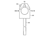
- the above two modes are automatically switched when the user operates the zoom lever 501 in FIG. That is, when performing screening observation, the zoom lever 501 is set to the position of the WIDE end, and when performing close-up magnification observation, the zoom magnification is switched stepwise by turning the zoom lever 501 to the TELE end.
- FIG. 5 is a diagram illustrating a change in the depth of field of the imaging system with respect to the operation of the zoom lever 501.
- the imaging system is an imaging system including an objective lens system 203 (including a zoom lens 205) and an imaging element 209. The same applies to the imaging system including the objective lens system 204 (including the zoom lens 206) and the imaging element 210.
- the zoom lens 205 is set to a wide viewing angle position LP1.
- the zoom lens 205 is set to positions LP2 to LP4 by moving the zoom lever 501 stepwise (for example, in five steps) toward the TELE end.
- positions LP2 to LP4 the closer to the TELE side, the narrower the viewing angle, the closer the focusing distance, and the shallower the depth of field DF2 to DF4.
- the depth of field is shallow, but the closer observation is possible, and high magnification close-up observation is possible.
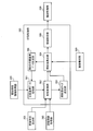
- FIG. 6 shows a detailed configuration example of the image processing unit 301 in the first embodiment.
- the image processing unit 301 includes a classification unit 310, an image configuration unit 320, an enhancement processing unit 330, a distance information acquisition unit 340 (distance map calculation unit), and a focus determination unit 370.
- a case where the pit pattern classification process is performed by the matching process will be described as an example, but various classification processes can be applied as described above.
- the distance information acquisition unit 340 acquires a stereo image output from the A / D conversion unit 211 and acquires distance information based on the stereo image. Specifically, the left image is used as a reference image, a matching operation with the local region of the right image is performed on the epipolar line passing through the pixel of interest located in the center of the local region of the left image, and the position having the maximum correlation is set as the parallax. calculate. Then, the calculated parallax is converted into a distance in the Z-axis direction to acquire distance information (for example, a distance map), and the distance information is output to the focus determination unit 370 and the classification unit 310.
- distance information for example, a distance map
- the distance information is various pieces of information acquired based on the distance from the imaging unit 200 to the subject.
- a distance based on an arbitrary point on a surface connecting two lenses generating parallax may be used as distance information.
- the distance information may be acquired by Time of Flight method. In this method, a subject is irradiated with laser light or the like, and the distance is measured based on the arrival time of the reflected light. In this case, for example, a distance based on each pixel position on the imaging element surface that captures the reflected light may be acquired as distance information.
- the reference point for distance measurement is set in the imaging unit 200, but the reference point may be set in any place other than the imaging unit 200.
- the reference point may be set at an arbitrary place in the three-dimensional space including the imaging unit 200 and the subject, and distance information when such a reference point is used is also included in the distance information of the present embodiment. .
- the distance from the imaging unit 200 to the subject is a distance in the depth direction from the imaging unit 200 to the subject, for example.
- the distance in the optical axis direction of the imaging unit 200 may be used. That is, the distance at a certain point on the subject is the distance from the imaging unit 200 to the subject on a line passing through that point and parallel to the optical axis.
- An example of such distance information is a distance map.
- the distance map is, for example, the distance (depth, depth) in the Z-axis direction to the subject for each point (for example, each pixel of the captured image) on the XY plane when the optical axis direction of the imaging unit 200 is the Z-axis. Is a map with the value of the point.
- the distance information acquisition unit 340 has a virtual position at a position where a magnitude relationship similar to the magnitude relationship of the distance values between pixels on the distance map acquired when the reference point is set in the imaging unit 200 can be maintained.
- distance information based on the distance from the imaging unit 200 to the corresponding point may be acquired. For example, when the actual distances from the imaging unit 200 to the three corresponding points are “3”, “4”, and “5”, the distances are uniformly maintained while maintaining the magnitude relationship of the distance values between the pixels. “1.5”, “2”, and “2.5” may be acquired.
- the image configuration unit 320 acquires a stereo image (left image and right image) output from the A / D conversion unit 211, and performs image processing (for example, OB processing) for converting the stereo image into an image that can be output to the display unit 400. , Gain processing, ⁇ processing, etc.).
- image processing for example, OB processing
- the image construction unit 320 outputs the processed image to the classification unit 310 and the enhancement processing unit 330.
- the focus determination unit 370 divides each pixel or each region of the captured image (for example, the captured image into regions of a predetermined size) by comparing the distance from the image capturing unit 200 to the subject and the depth of field of the image capturing unit 200. In each case, the focus determination is performed.
- FIG. 7 shows a detailed configuration example of the focus determination unit 370.
- the focus determination unit 370 includes a distance information correction unit 371 (distance map correction unit), a depth of field acquisition unit 372, a comparison unit 373, and a focus determination map output unit 374.
- the distance information is a distance map.
- the distance information correction unit 371 performs a low-pass filter process of a predetermined size of N ⁇ N pixels on the distance map input from the distance information acquisition unit 340.
- the distance map corrected in this way is output to the comparison unit 373.
- the depth of field acquisition unit 372 is connected to the control unit 302, and information on the zoom lens position is input from the control unit 302. As described above, the zoom lens position is set by the zoom lever 501, and the relationship described in FIG. 5 exists between the zoom lens position, the distance to the subject to be focused, and the depth of field. is there. Based on the input zoom lens position information, the depth-of-field acquisition unit 372 determines a focusing range (a range of distance to a subject to be focused) using, for example, a lookup table, and the focusing is performed. The range is output to the comparison unit 373.
- the look-up table may be set in advance based on the characteristics of the objective lens system 203 and 204.
- the comparison unit 373 compares the distance map input from the distance information correction unit 371 with the focus range information input from the depth-of-field acquisition unit 372 for each pixel, and whether each pixel is in focus or not. Determine.
- the focus determination result is output to the focus determination map output unit 374.
- the focus determination map output unit 374 creates a focus determination map based on the focus determination result input from the comparison unit, and outputs the focus determination map to the classification unit 310.
- the focus determination map is, for example, a map in which “1” is stored in the focused pixel and “0” is stored in the non-focused pixel. Data of the same size (the same number of pixels).
- the classification unit 310 performs a classification process for each pixel (or region) in the image based on the distance information and the classification standard. Specifically, the classification unit 310 includes a surface shape calculation unit 350 (three-dimensional shape calculation unit) and a classification processing unit 360. Details of the classification processing performed by the classification unit 310 will be described later, and an outline will be described here.
- the surface shape calculation unit 350 calculates the normal vector of the subject surface at each pixel of the distance map as surface shape information (three-dimensional shape information in a broad sense). Then, the classification processing unit 360 projects the reference pit pattern onto the subject surface based on the normal vector. Further, based on the distance at the pixel position, the size of the reference pit pattern is adjusted to the size on the image (that is, the apparent size that is smaller on the image as the distance is longer). The classification processing unit 360 performs matching processing between the reference pit pattern corrected in this way and the image, and detects an area that matches the reference pit pattern.
- the classification processing unit 360 sets the normal pit pattern shape as a reference pit pattern, classifies the region GR1 that matches the reference pit pattern as a “normal portion”, and does not match the region GR2 Is classified as “abnormal part” (non-normal part, lesion part).
- the classification processing unit 360 corrects the classification based on the result of the focus determination. Specifically, the classification of the region GR3 determined to be out of focus by the focus determination unit 370 is corrected to “unknown”. Alternatively, the out-of-focus pixels are excluded from the matching process and the classification is set to “unknown”, and the other pixels are matched and classified as “normal” and “abnormal”. Also good.
- the classification processing unit 360 outputs the classification result to the enhancement processing unit 330.
- unknown means that it is unknown which class it belongs to in classification processing classified into categories according to the type of structure, the state of normal / abnormality, etc., and the classification according to the degree of abnormality. For example, when classifying into “normal part” and “abnormal part”, those that cannot be determined (or are not determined) to belong to “normal part” or “abnormal part” are classified as “unknown”.
- the enhancement processing unit 330 Based on the classification result from the classification unit 310, the enhancement processing unit 330 performs a desired enhancement process on one of the stereo images output from the image configuration unit 320 (for example, a left image that is a reference for parallax calculation). Only for this, the processed image is output to the display unit 400. That is, the enhancement processing unit 330 does not output a stereoscopic image, and the display unit 400 performs 2D image display. For example, no enhancement processing is performed on the region GR1 whose classification result is “normal portion”, enhancement processing for luminance is performed on the region GR2 which is “abnormal portion”, and the region GR3 which is “unknown” is displayed. Performs processing to replace the pixel value with a specific color.
- the specific color to be replaced is preferably a unique color that is not included in a normal subject.
- the user wants to observe an area displayed in a specific color, the user operates the zoom lever 501 or changes the relative distance between the imaging unit 200 and the subject so that the area becomes a focused area. To do. By performing such an operation, the user can obtain a new classification result and observe the region.
- the classification unit 310 outputs a classification result (for example, “unknown”) corresponding to out-of-focus for a pixel or region in which it is determined that the subject is out-of-focus. Specifically, the classification unit 310 corrects the result of the classification process to the classification corresponding to the out-of-focus state for the pixel or the region in which the subject is determined to be out-of-focus.
- a classification result for example, “unknown”
- the classification result of the part where the subject is not in focus in the image is not output, the classification is different from the actual subject state in the part where the image is unclear due to defocusing. Even if it is misclassified, the misclassification is not highlighted. Thereby, the reliability of highlighting can be improved, and accurate information can be presented to the user to assist diagnosis.
- the classification unit 310 determines whether or not a pixel or a region matches a characteristic of a normal structure (for example, a basic pit as described later with reference to FIG. 16A). The area is classified into a normal part and an abnormal part (abnormal part). Then, the classification unit 310 corrects the classification result of the normal part and the abnormal part to the unknown state in which the classification of the normal part and the abnormal part is unknown for the pixel or the region in which the subject is determined to be out of focus. To do.
- a normal structure for example, a basic pit as described later with reference to FIG. 16A.
- the subject can be classified into, for example, a normal part where a normal pit pattern exists and a non-normal part other than that. Then, it can be prevented that the portion in which the image is unclear due to the out-of-focus state is erroneously classified into the non-normal portion even though the normal pit pattern actually exists.
- the abnormal parts may be further grouped into subdivided classifications. Even in such a case, the subdivided classification may be erroneously determined by motion blur, but according to the present embodiment, such erroneous determination can be suppressed.
- the classification unit 310 may exclude pixels or regions in which the subject is determined to be out-of-focus from the target of the classification process and set the classification or classification corresponding to out-of-focus.
- misclassification can be suppressed and accurate information can be presented to the user.
- the classification result of the out-of-focus area to “unknown (unknown state)”
- the matching process is not performed on the out-of-focus pixel or region, the processing load can be reduced.
- FIG. 9 shows a configuration example of an endoscope device according to the second embodiment.
- the endoscope apparatus includes a light source unit 100, an imaging unit 200, a processor unit 300, a display unit 400, and an external I / F unit 500.
- the same components as those in the first embodiment are denoted by the same reference numerals, and description thereof will be omitted as appropriate.
- the difference from the first embodiment is the configuration of the objective lens systems 203 and 204 of the imaging unit 200. That is, the objective lens systems 203 and 204 further include focus lenses 214 and 215.
- the imaging unit 200 further includes focus lens driving units 216 and 217 that drive the focus lenses 214 and 215.
- the focus lens driving units 216 and 217 are, for example, VCMs.
- the processor unit 300 further includes a focus control unit 303.
- FIG. 10 shows a configuration example of the external I / F unit 500 in the second embodiment.
- the external I / F unit 500 includes a zoom lever 501 and an AF button 502.
- the zoom lever 501 can be operated continuously within a certain range, and the user can continuously adjust the zoom lens position from the WIDE end to the TELE end by moving the zoom lever 501.
- the external I / F unit 500 outputs position information of the zoom lever 501 to the control unit 302.
- the external I / F unit 500 outputs an AF start signal to the control unit 302 when the AF button 502 is pressed.
- FIG. 11 shows a detailed configuration example of the focus control unit 303.
- the focus control unit 303 includes a focus lens drive mode determination unit 381, a focus lens position determination unit 382, and an AF control unit 383 (AF: autofocus).
- AF autofocus
- the focus lens drive mode determination unit 381 determines the focus lens drive mode based on the zoom lens position information and AF start information input from the control unit 302.
- the focus lens drive mode determination unit 381 selects the fixed focus mode when the zoom lens position is located on the WIDE side with respect to a predetermined position, and uses the zoom lens position information as the focus lens position determination unit 382. Output to.
- the focus lens drive mode determination unit 381 selects the fixed focus mode even when the zoom lens position is closer to the TELE side than the predetermined position and no AF start signal is input from the external I / F unit 500. Information on the zoom lens position is output to the focus lens position determination unit 382.
- the focus lens position determination unit 382 determines the focus lens position based on the zoom lens position information, and outputs the determined focus lens position information to the focus lens driving units 216 and 217. Since the focus changes when the zoom lens position changes, for example, a table in which the position of the focus lens that realizes the fixed focus is associated with each zoom lens position is stored, and the position of the focus lens is referred to by referring to the table. Just decide.
- the focus lens driving units 216 and 217 drive the focus lenses 214 and 215 based on the focus lens position information input from the focus lens position determination unit 382.
- the focus lens drive mode determination unit 381 selects the AF mode when the zoom lens position is closer to the TELE side than the predetermined position and an AF start signal is input from the external I / F unit 500, and AF start The signal is output to the AF control unit 383.
- the AF control unit 383 outputs an AF status signal set to a status of “being executed” to the image processing unit 301 and starts an AF operation. To do.
- the AF control unit 383 calculates a contrast value from the image input from the image processing unit 301, and drives the focus lenses 214 and 215 based on a known contrast AF method.
- the AF control unit 383 outputs information on the focus lens position to the image processing unit 301 every time the focus lenses 214 and 215 are driven.
- the AF control unit 383 determines whether or not the in-focus state is obtained from the calculated contrast value. When the in-focus state is determined, the AF operation is terminated and the AF status signal set to the status of “stopped”. Is output to the image processing unit 301.
- the reason why the fixed focus mode and the AF mode are switched depending on the zoom lens position is that the depth of field differs depending on the zoom lens position as described with reference to FIG. That is, when the zoom lens position is on the WIDE side, the depth of field is sufficiently deep and AF control is not required. However, when the zoom lens position is on the TELE side, the depth of field becomes shallow and AF control is performed. Is based on the assumption that
- FIG. 12 shows a detailed configuration example of the focus determination unit 370 in the second embodiment.
- the focus determination unit 370 includes a distance information correction unit 371, a depth of field acquisition unit 372, a comparison unit 373, and a focus determination map output unit 374.
- the basic configuration is the same as in the first embodiment. The difference is that not only the control unit 302 but also the AF control unit 383 is connected, and the operation of the depth of field acquisition unit 372.
- the AF status signal input from the AF control unit 383 is “stopped” (that is, the fixed focus mode)
- the operation of the depth of field acquisition unit 372 is the same as that of the first embodiment.
- the depth-of-field acquisition unit 372 receives the zoom position information input from the control unit 302 and the focus lens input from the AF control unit 383. Based on the position information, a focus range is determined using a preset look-up table or the like, and the determined focus range is output to the comparison unit 373.
- classification processing unit 360 in the second embodiment will be described.
- the classification processing unit 360 is connected to the AF control unit 383.
- the operation of the classification processing unit 360 is the same as that of the first embodiment.
- the classification processing unit 360 When the AF status signal is “being executed”, the classification processing unit 360 performs a matching process between the classification standard corrected based on the distance information and the image, and classifies the subject into, for example, “normal part” and “abnormal part”. To do. Further, the classification processing unit 360 corrects the classification based on the focus determination map input from the focus determination unit 370. The classification processing unit 360 holds a plurality of classification results and a plurality of in-focus determination maps during a period in which the AF status signal is “in execution”. Then, one corrected classification is determined based on a plurality of classification results and a plurality of focus determination maps.
- a plurality of in-focus maps are compared, and a pixel having an in-focus map that is determined to be in focus is classified into a classification obtained by correcting the classification result at the time of in-focus. Pixels for which there is no in-focus map that is determined to be in focus are corrected to an unknown classification.
- the classification processing unit 360 outputs the classification result classified as “normal part”, “abnormal part”, or “unknown” to the enhancement processing unit 330.
- the operation of the classification processing unit 360 will be described using FIG. 13 as an example in which the classification is corrected using the focus determination map of the two frames F1 and F2.
- the frames F1 and F2 are a series of frames taken during the AF operation. Since the in-focus range varies depending on the movement of the lens position in the AF operation, the “in-focus” area is different for each frame in the in-focus determination map.
- the area AA1 is “in focus” and the other area AA2 is “out of focus” in the focus determination map of the frame F1.
- the area AA1 is classified as “normal”, and the area AA2 is classified as “abnormal part” because the image is blurred.
- This classification map is corrected by the focus determination map, and the area AA2 is reclassified to “unknown”.
- the “in-focus” area AB1 is classified as “normal”, and the classification of the “in-focus” area AB2 is corrected from “abnormal” to “unknown”.
- the corrected classification maps of the frames F1 and F2 are compared, and a pixel that is “normal” is classified as “normal”, and a pixel that is “unknown” is classified as “unknown”. .
- the area AC1 obtained by combining the “normal” areas AA1 and AB1 in the frames F1 and F2 is classified as “normal” and output as a final classification map.
- the AF control unit 383 controls the autofocus operation of the imaging unit 200. Then, the focus determination unit 370 determines whether or not the subject is in focus in each frame of a plurality of frames (for example, frames F1 and F2) that perform the autofocus operation.
- the classification unit 310 applies the classification processing result in the frame (the “normal part” of the regions AA1 and AB1 in FIG. 13) for the pixel or region in which the subject is determined to be in focus in any one of the plurality of frames. ”) As a final classification result (" normal part "of the area AC1).
- the final classification result can be output by using the information (focus determination map, classification map) acquired at a plurality of focus lens positions in combination.
- the information focus determination map, classification map
- Area can be narrowed. Thereby, it is possible to display the classification result with high reliability performed in the in-focus area in a wider area.
- First classification processing method 4.1 Classification Unit
- the classification process performed by the classification unit 310 according to the first and second embodiments described above will be described in detail.
- FIG. 14 shows a detailed configuration example of the classification unit 310.
- the classification unit 310 includes a known characteristic information acquisition unit 345, a surface shape calculation unit 350, and a classification processing unit 360.
- the operation of the classification unit 310 will be described taking the case where the observation target is the large intestine as an example.
- the living body surface 1 of the large intestine to be observed has a polyp 2 of a raised lesion, and the mucosal surface layer of the polyp 2 has a normal gland duct 40 and an abnormal gland duct 50. It shall be.
- a concave lesion 60 in which the gland duct structure has disappeared exists at the base of the polyp 2.
- the normal gland duct 40 has a substantially circular shape
- the abnormal gland duct 50 has a shape that is different from that of the normal gland duct 40. Presents.
- the surface shape calculation unit 350 performs a closing process or an adaptive low-pass filter process on the distance information (for example, a distance map) input from the distance information acquisition unit 340, thereby obtaining a size equal to or larger than the size of the predetermined structural element. Extract the structure.
- the predetermined structural element is a gland duct structure (pit pattern) to be classified and determined formed on the biological surface 1 of the observation site.
- the known characteristic information acquisition unit 345 acquires structural element information as one of the known characteristic information, and outputs the structural element information to the surface shape calculation unit 350.
- the structural element information is size information determined by the optical magnification of the imaging unit 200 and the size (width information) of the gland duct structure to be classified from the surface structure of the living body surface 1. That is, the optical magnification is determined according to the distance to the subject, and the size on the image of the gland duct structure imaged at that distance is acquired as the structural element information by adjusting the size with the optical magnification.
- the control unit 302 of the processor unit 300 stores the standard size of the gland duct structure, and the known characteristic information acquisition unit 345 acquires the size from the control unit 302 and performs size adjustment based on the optical magnification.
- the control unit 302 determines an observation site based on scope ID information input from the memory 212 of the imaging unit 200. For example, when the imaging unit 200 is an upper digestive scope, the observation site is determined to be the esophagus, stomach, and duodenum, and when the imaging unit 200 is the lower digestive scope, the observation site is determined to be the large intestine. In the control unit 302, standard gland duct sizes corresponding to these observation sites are recorded in advance.
- a method for determining an observation site other than the scope ID for example, there is a method in which the external I / F unit 500 has a switch that can be operated by the user, and the user selects the observation site using the switch.
- the surface shape calculation unit 350 adaptively generates surface shape calculation information based on the input distance information, and calculates the surface shape information of the subject using the surface shape calculation information.
- the surface shape information is, for example, a normal vector NV shown in FIG. Details of the surface shape calculation information will be described later.
- the generated surface shape information is input to the classification processing unit 360 together with the distance map.
- the classification processing unit 360 generates a corrected pit (classification standard) by adapting the basic pit to the three-dimensional shape of the living body surface of the captured image.
- the basic pit is obtained by modeling one normal gland duct structure for classifying the gland duct structure, and is, for example, a binary image.
- the terms basic pit and correction pit are used. However, a broader term can be replaced with a reference pattern and a correction pattern.
- the classification processing unit 360 performs a classification process based on the generated classification standard (corrected pit). Specifically, an image from the image construction unit 320 is further input to the classification processing unit 360. The classification processing unit 360 determines whether or not the corrected pit is present on the captured image by a known pattern matching process, and outputs a classification map in which the classification areas are grouped to the enhancement processing unit 330.
- the classification map is a map in which captured images are classified into an area where a correction pit exists and other areas. For example, it is a binary image in which “1” is assigned to the pixels in the area where the correction pit exists and “0” is assigned to the pixels in the other areas. In the case where the classification of “unknown” is set according to the focus determination, for example, “2” may be assigned to the pixels in the “unknown” area to form a ternary image.
- the image from the image construction unit 320 (the same size as the classified image) is further input to the enhancement processing unit 330.
- the enhancement processing unit 330 performs enhancement processing on the image output from the image construction unit 320 using information indicating the classification result.
- FIG. 15A is a cross-sectional view of the living body surface 1 of the subject and the imaging unit 200 in a cross section along the optical axis of the imaging unit 200, and shows a state in which the surface shape is calculated by morphological processing (closing processing). It is a schematic one.
- the radius of the sphere SP (structural element) used for the closing process is, for example, at least twice (including its value) the size (surface shape calculation information) of the gland duct structure to be classified. As described above, the size of the duct structure is adjusted to the size on the image in accordance with the distance to the subject at each pixel.
- the surface 3 of the living body 1 that is smoother than the minute irregularities without picking up the minute irregularities of the normal gland duct 40, the abnormal gland duct 50, and the gland duct disappearing region 60 is used.
- Dimensional surface shape can be extracted. Therefore, the correction error can be reduced as compared with the case where the basic pit is corrected to the corrected pit using the surface shape with minute unevenness left.
- FIG. 15B is a cross-sectional view of the surface of the living body after the closing process, and schematically shows a result of calculating the normal vector NV with respect to the surface of the living body.
- the surface shape information is this normal vector NV.
- the surface shape information is not limited to the normal vector NV, and may be the curved surface itself after the closing process shown in FIG. 15B, or other information that can express the surface shape. Also good.
- the known characteristic information acquisition unit 345 acquires the gland duct size (width in the longitudinal direction, etc.) inherent to the living body as known characteristic information, and uses that information to trace the actual living body surface by the closing process.
- the radius of the sphere SP (radius corresponding to the size of the gland duct on the image) is determined. At this time, the radius of the sphere SP is set to a radius larger than the size of the gland duct on the image.
- the surface shape calculation unit 350 can extract only a desired surface shape by performing a closing process using the sphere SP.
- FIG. 17 shows a detailed configuration example of the surface shape calculation unit 350.
- the surface shape calculation unit 350 includes a morphological characteristic setting unit 351, a closing processing unit 352, and a normal vector calculation unit 353.
- the known characteristic information acquisition unit 345 inputs the size of the gland duct unique to the living body (width in the longitudinal direction, etc.), which is known characteristic information, to the morphological characteristic setting unit 351.
- the morphological characteristic setting unit 351 determines surface shape calculation information (such as the radius of the sphere SP used for the closing process) based on the size of the gland duct and the distance map.
- the radius information of the determined sphere SP is input to the closing processing unit 352 as a radius map having the same number of pixels as the distance map, for example.
- the radius map is a map in which information on the radius of the sphere SP at each pixel is associated with each pixel.
- the closing processing unit 352 performs the closing process by changing the radius in units of pixels based on the radius map, and outputs the processing result to the normal vector calculation unit 353.
- the distance vector after the closing process is input to the normal vector calculation unit 353.
- the normal vector calculation unit 353 has three-dimensional information (for example, pixel coordinates and distance information at the coordinates) at the target sample position on the distance map, and 3 at two sample positions adjacent to the target sample position. A plane is defined based on the dimension information, and a normal vector of the defined plane is calculated.
- the normal vector calculation unit 353 outputs the calculated normal vector to the classification processing unit 360 as a normal vector map having the same sampling number as the distance map.
- FIG. 18 shows a detailed configuration example of the classification processing unit 360.
- the classification processing unit 360 includes a classification reference data storage unit 361, a projective transformation unit 362, a search region size setting unit 363, a similarity calculation unit 364, and a region setting unit 365.
- the classification reference data storage unit 361 stores basic pits that model normal gland ducts exposed on the surface of a living body shown in FIG. This basic pit is a binary image, which is an image having a size corresponding to a case where a normal gland duct at a predetermined distance is imaged.
- the classification reference data storage unit 361 outputs this basic pit to the projective transformation unit 362.
- the projection conversion unit 362 receives the distance map from the distance information acquisition unit 340, the normal vector map from the surface shape calculation unit 350, and the optical magnification from the control unit 302 (not shown).
- the projective transformation unit 362 extracts distance information of the target sample position from the distance map, and extracts a normal vector of the corresponding sample position from the normal vector map. Then, as shown in FIG. 16B, projective transformation of the basic pit is performed using the normal vector, and magnification correction is performed in accordance with the optical magnification to generate a corrected pit.
- Projection conversion unit 362 outputs the corrected pit as a classification reference to similarity calculation unit 364 and outputs the size of the corrected pit to search region size setting unit 363.
- the search area size setting unit 363 sets an area that is twice as long as the corrected pit size as a search area for the similarity calculation process, and outputs information on the search area to the similarity calculation unit 364.
- the similarity calculation unit 364 receives a corrected pit at the target sample position from the projective conversion unit 362 and a search area corresponding to the corrected pit from the search area size setting unit 363. The similarity calculation unit 364 extracts the image of the search area from the image input from the image construction unit 320.
- the similarity calculation unit 364 performs high-pass filter processing or band-pass filter processing on the extracted search region image to cut low-frequency components, and binarization processing is performed on the filtered image. To generate a binary image of the search area. Then, the correlation value is calculated by performing pattern matching processing on the binary image in the search area with the corrected pit, and a map of the peak position of the correlation value and the maximum correlation value is output to the area setting unit 365. For example, the correlation value is the sum of absolute differences, and the maximum correlation value is the minimum value of the sum of absolute differences.
- POC Phase Only Correlation
- the region setting unit 365 Based on the maximum correlation value map input from the similarity calculation unit 364, the region setting unit 365 extracts a region where the sum of absolute differences is equal to or less than a predetermined threshold T (including that value), and further, A three-dimensional distance between the position of the maximum correlation value and the position of the maximum correlation value in the adjacent search range is calculated. If the calculated three-dimensional distance is included in the range of the predetermined error, the region including the maximum correlation position is grouped as a normal region, and a classification map is generated. The region setting unit 365 outputs the generated classification map to the enhancement processing unit 330.
- T including that value
- a position in an image is set as a processing target position.
- the projective transformation unit 362 acquires a correction pattern at the processing target position by deforming the reference pattern based on the surface shape information at the processing target position.
- the search area size setting unit 363 searches the search area around the processing target position from the acquired correction pattern (in the above example, an area having a size twice the vertical and horizontal directions of the correction pattern). ) Is set.
- the similarity calculation unit 364 matches the imaged structure and the correction pattern in the search area. If this matching is performed on a pixel basis, the similarity is calculated for each pixel. Then, as illustrated in FIG. 19E, the region setting unit 365 identifies a pixel corresponding to the similarity peak in the search region, and whether or not the similarity in the pixel is equal to or greater than a given threshold value. Determine whether. If the similarity is greater than or equal to the threshold value, correction is made to a region of the size of the correction pattern with reference to the peak position (in FIG. 19E, the center position of the correction pattern is used as the reference position, but is not limited to this). Since the pattern is detected, the area can be classified as an area that matches the reference pattern.
- the inside of the shape representing the correction pattern may be an area that matches the classification criteria, and various modifications can be made.
- the similarity is less than the threshold value, there is no structure matching the reference pattern in the peripheral region of the processing target position.
- a region that matches zero, one, or a plurality of reference patterns and other regions are set in the captured image. If there are a plurality of regions that match the reference pattern, the classification results are finally obtained by integrating those overlapping or adjacent ones.
- the classification processing method based on the similarity described here is an example, and the classification processing may be performed by another method.
- specific methods for calculating the similarity various methods for calculating the similarity between images and the difference between images are known, and detailed description thereof will be omitted.
- the classification unit 310 generates the classification reference based on the surface shape calculation unit 350 that obtains the surface shape information of the subject based on the distance information and the known characteristic information, and generates the classification reference based on the surface shape information.
- a classification processing unit 360 that performs a classification process using the classification criterion.
- There are various factors that can reduce the accuracy of the classification process depending on the surface shape such as the deformation of the structure on the captured image caused by the angle formed by the optical axis direction of the imaging unit 200 and the surface of the subject. Therefore, even in such a case, classification processing can be performed with high accuracy.
- the known characteristic information acquisition unit 345 acquires a reference pattern corresponding to the structure of the subject in a given state as known characteristic information, and the classification processing unit 360 is based on the surface shape information with respect to the reference pattern.
- a correction pattern acquired by performing the deformation process may be generated as a classification standard, and the classification process may be performed using the generated classification standard.
- the known characteristic information acquisition unit 345 acquires a reference pattern corresponding to the structure of the subject in a normal state as acquisition of known characteristic information.
- An abnormal region is a region suspected of being a lesioned part of a living body, for example, in the case of an endoscope for a living body. Since it is assumed that such a region has a high degree of attention for the user, it is possible to suppress oversight of a region to be noticed by appropriately classifying the region.
- the subject has a global three-dimensional structure and a local uneven structure compared to the global three-dimensional structure, and the surface shape calculation unit 350 has a global three-dimensional structure that the subject has.
- surface shape information may be obtained by extracting a global three-dimensional structure from the distance information.
- the classification process can be performed with high accuracy by obtaining the surface shape information from the global three-dimensional structure.
- FIG. 20 shows a detailed configuration example of the classification processing unit 360 in the second classification processing method.
- the classification processing unit 360 includes a classification reference data storage unit 361, a projective transformation unit 362, a search region size setting unit 363, a similarity calculation unit 364, a region setting unit 365, and a second classification reference data generation unit 366.
- symbol is attached
- the basic pit that is the classification standard is prepared not only for the normal gland duct but also for the abnormal gland duct, and the pit of the actual captured image is extracted, and the second classification standard data
- the classification reference data is replaced as (second reference pattern), and the similarity is recalculated based on the second classification reference data after the replacement.
- the pit pattern on the surface of the living body depends on whether it is in a normal state or an abnormal state. It is known that the shape changes depending on the degree of progress of the above. For example, in the case of a normal mucous membrane, the pit pattern is almost circular as shown in FIG. 22 (A), and when the lesion progresses, the star pod shape in FIG. 22 (B), or in FIG. 22 (C) and FIG. If it becomes a complicated shape such as a tubular type and further proceeds, the pit pattern disappears as shown in FIG. Therefore, it is possible to determine the state of the subject by holding these typical patterns as reference patterns and determining the degree of similarity between the surface of the subject captured in the captured image and the reference pattern. .
- the classification reference data storage unit 361 not only basic pits of normal ducts but also a plurality of pits as shown in FIG. 21 are recorded, and these pits are output to the projective conversion unit 362.
- the processing of the projective transformation unit 362 is the same as the first classification processing method. That is, projective transformation processing is performed on all the pits stored in the classification reference data storage unit 361, and corrected pits for a plurality of classification types are output to the search area size setting unit 363 and the similarity calculation unit 364.
- the similarity calculation unit 364 generates respective maximum correlation value maps for a plurality of corrected pits. Note that the maximum correlation value map at this point is not used for generation of the classification map (generation of the final output of the classification process), but is output to the second classification reference data generation unit 366 to generate new classification reference data. Will be used to generate
- the second classification criterion data generation unit 366 newly classifies the pit image at the position on the image determined by the similarity calculation unit 364 as having high similarity (for example, the difference absolute value is equal to or less than a predetermined threshold). Adopt as. Thereby, since the pit extracted from the actual image is used as the classification reference instead of the standard modeled pit prepared in advance, the classification determination with more optimum accuracy is possible.
- the second classification reference data generation unit 366 includes a maximum correlation value map for each classification from the similarity calculation unit 364, an image from the image configuration unit 320, and a distance from the distance information acquisition unit 340.
- the map, the optical magnification from the control unit 302, and the gland duct size for each classification from the known characteristic information acquisition unit 345 are input. Then, the second classification reference data generation unit 366 extracts image data corresponding to the sample position of the maximum correlation value for each classification based on the distance information of the position, the size of the gland duct, and the optical magnification.
- the second classification reference data generation unit 366 acquires a grayscale image (in order to cancel the difference in brightness) obtained by removing the low frequency component from the extracted actual image, and uses the grayscale image as the second classification.
- the reference data is output to the classification reference data storage unit 361 together with the normal vector and the distance information.
- the classification reference data storage unit 361 stores the second classification reference data and related information. As a result, the second classification reference data having high correlation with the subject can be collected in each classification.
- the second classification reference data described above excludes the influence of deformation (change in size) due to the angle between the optical axis direction of the imaging unit 200 and the subject surface and the distance from the imaging unit 200 to the subject surface.
- the second classification reference data generation unit 366 may generate the second classification reference data after performing a process for canceling the influence thereof.
- the result of performing deformation processing (projection conversion processing and scaling processing) on the gray scale image so as to correspond to the case where the image is captured at a given distance from a given reference direction. May be the second classification reference data.
- the projection conversion unit 362, the search area size setting unit 363, and the similarity calculation unit 364 may perform the process again for the second classification reference data. Specifically, projective transformation processing is performed on the second classification reference data to generate a second correction pattern, and the same processing as the first classification processing method is performed using the generated second correction pattern as a classification reference. I do.
- the region setting unit 365 is grouped according to the classification map (I type, II type,%) Shown in FIG. 21 or according to the classification type (type A, B,...) Shown in FIG. Generate a classification map. Specifically, a classification map is generated for areas that have been correlated with corrected pits that are classified as normal ducts, and a classification map for areas that have been correlated with corrected pits that are classified as abnormal ducts is classified by category. Generate by type. Then, a classification map (multi-valued image) obtained by combining these classification maps is generated. When synthesizing, the overlapping area of the areas where the correlation is obtained in each classification may be an unclassified area or may be replaced with a classification with a higher malignancy level. The region setting unit 365 outputs the combined classification map to the enhancement processing unit 330.
- the enhancement processing unit 330 performs, for example, luminance or color enhancement processing based on the multi-valued image classification map.
- the known characteristic information acquisition unit 345 acquires the reference pattern corresponding to the structure of the subject in the abnormal state as acquisition of the known characteristic information.
- FIG. 21 it is possible to acquire a plurality of reference patterns, generate a classification reference using them, and perform a classification process. That is, by performing classification processing using typical patterns as shown in FIGS. 22A to 22F as reference patterns, the state of the subject can be classified in detail.
- the known characteristic information acquisition unit 345 acquires a reference pattern corresponding to the structure of the subject in a given state as known characteristic information, and the classification processing unit 360 is based on the surface shape information with respect to the reference pattern.
- a correction pattern is obtained by performing deformation processing, and the degree of similarity between the structure of the subject captured in the captured image and the correction pattern is obtained at each image position of the captured image, and based on the obtained similarity,
- a second reference pattern candidate may be acquired.
- category process part 360 produces
- the second correction pattern acquired by performing the deformation process based on the shape information may be generated as a classification standard, and the classification process may be performed using the generated classification standard.
- the classification reference since a classification reference can be created from the subject actually captured in the captured image, the classification reference well reflects the characteristics of the subject to be processed, and the reference pattern acquired as the known characteristic information is used. Compared with the case where it is used as it is, the accuracy of the classification process can be further improved.
- each unit configuring the image processing unit 301 is configured by hardware.
- the CPU may be configured to perform processing of each unit on an image and distance information acquired in advance using the imaging device, and may be realized as software by the CPU executing a program.
- a part of processing performed by each unit may be configured by software.
- the program stored in the information storage medium is read, and the read program is executed by a processor such as a CPU.
- the information storage medium (computer-readable medium) stores programs, data, and the like.
- Information storage media are equipped with CD-ROM and USB memory, as well as “portable physical media” including MO discs, DVD discs, flexible discs (FD), magneto-optical discs, IC cards, etc., inside and outside the computer system.
- Programs such as “fixed physical media” such as HDD, RAM, and ROM, public lines connected via modems, local area networks or wide area networks to which other computer systems or servers are connected It includes any recording medium that records a program that can be read by a computer system, such as a “communication medium” that stores a program in a short time during transmission.
- the program is recorded on the above recording medium so as to be readable by a computer, and the computer system (an apparatus including an operation unit, a processing unit, a storage unit, and an output unit) reads the program from such a recording medium.
- the computer system an apparatus including an operation unit, a processing unit, a storage unit, and an output unit
- the program is not limited to be executed by a computer system, and when another computer system or server executes the program, or when they cooperate to execute the program, The present invention can be similarly applied.
- the hardware image processing apparatus may be executed in the same manner, or a program describing the processing procedure of the method may be executed by the CPU. May be executed.
Landscapes
- Engineering & Computer Science (AREA)
- Health & Medical Sciences (AREA)
- Life Sciences & Earth Sciences (AREA)
- Physics & Mathematics (AREA)
- Surgery (AREA)
- General Health & Medical Sciences (AREA)
- General Physics & Mathematics (AREA)
- Theoretical Computer Science (AREA)
- Molecular Biology (AREA)
- Nuclear Medicine, Radiotherapy & Molecular Imaging (AREA)
- Medical Informatics (AREA)
- Biomedical Technology (AREA)
- Radiology & Medical Imaging (AREA)
- Optics & Photonics (AREA)
- Biophysics (AREA)
- Animal Behavior & Ethology (AREA)
- Pathology (AREA)
- Veterinary Medicine (AREA)
- Public Health (AREA)
- Heart & Thoracic Surgery (AREA)
- Computer Vision & Pattern Recognition (AREA)
- Multimedia (AREA)
- Signal Processing (AREA)
- Quality & Reliability (AREA)
- Data Mining & Analysis (AREA)
- Astronomy & Astrophysics (AREA)
- Geometry (AREA)
- Artificial Intelligence (AREA)
- General Engineering & Computer Science (AREA)
- Evolutionary Biology (AREA)
- Bioinformatics & Cheminformatics (AREA)
- Bioinformatics & Computational Biology (AREA)
- Evolutionary Computation (AREA)
- Endoscopes (AREA)
- Instruments For Viewing The Inside Of Hollow Bodies (AREA)
Abstract
画像処理装置は、被写体の像を含む撮像画像を取得する画像取得部305と、撮像の際の撮像部200から被写体までの距離に基づく距離情報を取得する距離情報取得部340と、その距離情報に基づいて、撮像画像の画素又は領域において被写体が合焦しているか否かの判定を行う合焦判定部370と、被写体の構造物の分類処理を行い、画素又は領域における判定の結果に応じて分類処理の対象を制御する分類部310と、その分類処理の結果に基づいて撮像画像の強調処理を行う強調処理部330と、を含む。
Description
本発明は、画像処理装置、内視鏡装置、プログラム及び画像処理方法等に関する。
従来、内視鏡診断において体腔内の病変検出精度を向上させたいという要求があり、病変部と正常部の組織上の違いを顕微鏡相当の倍率で近接拡大観察することで検出精度向上を達成する拡大光学系を備えた内視鏡(以降、拡大内視鏡と記す)が一般的に知られている。
このような拡大内視鏡には数十倍から数百倍の倍率を有したものがあり、色素散布によるコントラスト強調との併用により、粘膜表層の微細な構造を観察することができる。病変部と正常部ではこれらのパターンに違いが表れることが知られており、病変診断の1つの判定基準になっている。
また、色素散布を行うことなく、画像処理により表層粘膜の構造をよりコントラストを付けて表示する試みが行われている。例えば特許文献1には、局所的な抽出領域の注目画素の輝度レベルとその周辺画素の輝度レベルとを比較し、注目領域が周辺領域よりも暗い場合には着色する手法が開示されている。この手法は、距離が遠い場合には、生体表面から反射してくる反射光量が少なくなるため暗く撮像されるという仮定に基づいている。
また、病変部を選択的に強調表示することにより、病変部の見落とし防止や質的診断の精度を高める観察画像を提供する手法が考えられる。例えば特許文献2には、検体組織を撮像した画像に対するグリッド分割及び特徴量抽出により分類カテゴリ化を行い、分類毎に異なる態様の表示を行う手法が開示されている。
例えば、内視鏡装置により近接拡大観察を行う場合、高倍率になるに従って被写界深度が通常観察時に比べて極端に浅くなるという特徴がある。即ち、近接拡大観察時の撮像画像には、合焦している領域と合焦していない領域が発生する可能性がある。このような場合、合焦していない領域については、画像から得られる情報が十分でないため、病変部の強調表示を正確に行うことが困難となる。
例えば、生体表面の腺管構造(ピットパターンと呼ばれている)を強調表示する手法として、既知のピットパターン形状と画像とをマッチング処理して画像上のピットパターンを分類し、その分類結果を表示する手法が考えられる。画像上の非合焦領域では、実際にはピットパターンが存在する場所でもマッチング処理でピットパターンを検出できず、誤った分類結果となり、表示の信頼性が低下してしまう。
本発明の幾つかの態様によれば、強調表示の信頼性を向上可能な画像処理装置、内視鏡装置、プログラム及び画像処理方法等を提供できる。
本発明の一態様は、被写体の像を含む撮像画像を取得する画像取得部と、撮像の際の撮像部から前記被写体までの距離に基づく距離情報を取得する距離情報取得部と、前記距離情報に基づいて、前記撮像画像の画素又は領域において前記被写体が合焦しているか否かの判定を行う合焦判定部と、前記被写体の構造物の分類処理を行い、前記画素又は前記領域における前記判定の結果に応じて前記分類処理の対象を制御する分類部と、前記分類処理の結果に基づいて前記撮像画像の強調処理を行う強調処理部と、を含む画像処理装置に関係する。
本発明の一態様によれば、被写体の構造物の分類処理が行われ、その分類処理の対象が、撮像画像の画素又は領域において被写体が合焦しているか否かの判定結果に応じて制御され、その分類処理の結果に基づいて強調処理が行われる。これにより、強調表示の信頼性を向上することが可能になる。
また本発明の他の態様は、上記に記載の画像処理装置を含む内視鏡装置に関係する。
また本発明の更に他の態様は、被写体の像を含む撮像画像を取得し、撮像の際の撮像部から前記被写体までの距離に基づく距離情報を取得し、前記距離情報に基づいて、前記撮像画像の画素又は領域において前記被写体が合焦しているか否かの判定を行い、前記被写体の構造物の分類処理を行い、前記画素又は前記領域における前記判定の結果に応じて前記分類処理の対象を制御し、前記分類処理の結果に基づいて前記撮像画像の強調処理を行う、ステップをコンピューターに実行させるプログラムに関係する。
また本発明の更に他の態様は、被写体の像を含む撮像画像を取得し、撮像の際の撮像部から前記被写体までの距離に基づく距離情報を取得し、前記距離情報に基づいて、前記撮像画像の画素又は領域において前記被写体が合焦しているか否かの判定を行い、前記被写体の構造物の分類処理を行い、前記画素又は前記領域における前記判定の結果に応じて前記分類処理の対象を制御し、前記分類処理の結果に基づいて前記撮像画像の強調処理を行う画像処理方法に関係する。
以下、本実施形態について説明する。なお、以下に説明する本実施形態は、請求の範囲に記載された本発明の内容を不当に限定するものではない。また本実施形態で説明される構成の全てが、本発明の必須構成要件であるとは限らない。
1.本実施形態の概要
内視鏡装置によりピットパターンの分類処理を行う場合を例に本実施形態の概要について説明する。
内視鏡装置によりピットパターンの分類処理を行う場合を例に本実施形態の概要について説明する。
図1(A)に、異常部(例えば早期病変)を観察する際の撮像部200と被写体の関係を示す。また、図1(B)に、その際に取得した画像の例を示す。正常腺管40は正常なピットパターンを示し、異常腺管50は不整な形状を呈する異常なピットパターンを示し、腺管消失領域60は、病変によりピットパターンが消失した異常領域を示す。
図1(A)に示すように、術者は異常部(異常腺管50、腺管消失領域60)を発見すると、撮像部200を異常部に近接させ、撮像部200と異常部を極力正対させる。図1(B)に示すように、正常部(正常腺管40)のピットパターンでは規則的な構造が一様な配列で並んでいる。
本実施形態では、このような正常部を画像処理により検出するために、既知特性情報(先見情報)として正常なピットパターン構造を事前に登録又は学習し、マッチング処理等により正常部を検出する。一方、ピットパターンが不整な形状を呈したり消失したりしている異常部については、例えば正常なピットパターンが検出されなかった領域を異常部とみなして分類する。このようにしてピットパターンを正常部と異常部に分類し、その分類結果を強調表示することで、異常部の見落とし防止や質的診断の精度を上げることが可能となる。
しかしながら、マッチング処理等により分類を行う場合、画像の情報量が少ない領域では誤分類が生じる可能性がある。具体的には図1(A)に示すように、撮像部200を被写体に近づけて拡大観察を行う場合、被写界深度DAは非常に浅くなる(例えば数ミリメートル)。そのため、図1(B)に示すように、画像内に非合焦の領域RBが発生しやすくなる。このような領域RBではマッチング処理の精度が低下するため、本来は正常部に分類されるべき領域であっても誤って異常部に分類され、異常部として表示されてしまう可能性がある。
そこで図2に示すように、本実施形態の画像処理装置は、被写体の像を含む撮像画像を取得する画像取得部305と、撮像の際の撮像部200から被写体までの距離に基づく距離情報を取得する距離情報取得部340と、その距離情報に基づいて、撮像画像の画素又は領域において被写体が合焦しているか否かの判定を行う合焦判定部370と、被写体の構造物の分類処理を行い、画素又は領域における判定の結果に応じて分類処理の対象を制御する分類部310と、その分類処理の結果に基づいて撮像画像の強調処理を行う強調処理部330と、を含む。
このようにすれば、被写体の局所的な合焦/非合焦を判定することにより、被写界深度の範囲外であることによって分類結果の信頼性が低くなる領域RBを検出できる。そして、その検出結果に基づいて分類処理を行うことにより、信頼性の高い分類結果に基づいて強調表示できる。
例えば本実施形態では、分類処理の対象の制御として、非合焦と判定した画素又は領域をマッチング処理の対象から外し、ピットパターンの分類が不明であることを表す「不明」に分類する。或は、合焦判定の結果に関わらずマッチング処理を行い、非合焦と判定した画素又は領域を「不明」に再分類する。このようにして合焦判定に基づいて分類処理を行うことで、マッチング処理の精度低下による誤表示を防ぐことが可能である。
ここで距離情報とは、撮像画像の各位置と、その各位置での被写体までの距離とが対応付けられた情報であり、例えば撮像部200の光軸方向における距離を各画素に対応付けた距離マップである。なお後述するように、距離情報は距離マップに限定されず、撮像部200から被写体までの距離に基づいて取得される種々の情報であればよい。
また分類処理とは、ピットパターンの分類処理に限らず、被写体の構造物を例えば種類や状態等に応じて分類する処理であればよい。構造物とは、分類結果をユーザーに提示することによってユーザーの観察や診断をアシストし得るものであり、例えば生体用の内視鏡装置であれば、ピットパターンに限らず、粘膜に生じたポリープや、消化管の襞、血管、癌等の病変であってもよい。分類処理では、それらの種類や、例えば正常/異常等の状態、或は異常度に応じた区分に分類する。
なお具体的な分類処理としては、種々の分類処理を想定できる。例えば、後述する分類手法のように、距離情報から被写体表面の形状を求め、その形状に合わせて変形した基準ピットパターンと画像とをマッチング処理し、そのマッチング結果により画像上のピットパターンを分類してもよい。或は、距離情報を用いた変形を行わずに、基準ピットパターンと画像とを例えばPOC(Phase Only Correlation)等でマッチング処理し、ピットパターンを分類してもよい。
或は、ポリープや溝などの特定の構造を抽出することにより被写体を分類してもよい。例えば、ステレオ画像をステレオマッチング処理して距離マップを取得し、その距離マップに対してローパスフィルター処理やモルフォロジー処理等を行うことにより、被写体の大局的な形状の情報を取得する。そして、その大局的な形状の情報を距離マップから減算して局所的な凹凸構造の情報を取得する。そして、分類したい構造の既知特性情報(例えば特定のポリープが有するサイズや形状、或は病変特有の溝などの深さや幅等)と、局所的な凹凸構造の情報とを比較し、既知特性情報に合致する凹凸構造を抽出する。このようにして、ポリープや溝などの特定の構造を分類することができる。
また強調処理とは、画像上の特定の対象を目立たせる処理或は識別させる処理である。例えば、特定の種類や状態に分類された領域を構造強調や色強調等する処理であってもよいし、或は、その領域をハイライトする処理や、その領域を線で囲む処理、その領域を示すマークを付す処理であってもよい。また、特定の領域以外の領域に対して上記のような処理を行うことによって、その特定の領域を目立たせて(或は識別させて)もよい。
2.第1の実施形態
2.1.内視鏡装置
図3に、第1の実施形態における内視鏡装置の構成例を示す。内視鏡装置は、光源部100と撮像部200とプロセッサー部300(制御装置)と表示部400と外部I/F部500と、を含む。
2.1.内視鏡装置
図3に、第1の実施形態における内視鏡装置の構成例を示す。内視鏡装置は、光源部100と撮像部200とプロセッサー部300(制御装置)と表示部400と外部I/F部500と、を含む。
光源部100は、白色光源101と、複数の分光透過率を持った回転色フィルター102と、回転色フィルター102を駆動する回転駆動部103と、回転色フィルター102からの分光特性を持った光をライトガイドファイバー201の入射端面に集光させる集光レンズ104と、を含む。
回転色フィルター102は、三原色の赤の色フィルターと緑の色フィルターと青の色フィルターと回転モーターとから構成されている。
回転駆動部103は、プロセッサー部300の制御部302からの制御信号に基づいて撮像素子209、210の撮像期間と同期して回転色フィルター102を所定回転数で回転させる。例えば回転色フィルター102を1秒間に20回転させると、各色フィルターは60分の1秒間隔で入射白色光を横切ることになる。撮像素子209、210は、60分の1秒間隔で、3原色の各色光(R或いはG或いはB)に対する観察対象からの反射光を撮像し、画像の転送を完了することになる。つまり、この構成例では、R画像、G画像、B画像が60分の1秒間隔で面順次で撮像され、実質のフレームレートは20fpsとなる。
撮像部200は、例えば胃や大腸などの体腔への挿入を可能にするため細長くかつ湾曲可能に形成されている。撮像部200は、光源部100で集光された光を導くためのライトガイドファイバー201と、ライトガイドファイバー201により先端まで導かれた光を拡散させて観察対象に照射する照明レンズ202と、観察対象から戻る反射光を集光する対物レンズ系203、204と、を含む。対物レンズ系203は、光学倍率を調整するズームレンズ205を含み、対物レンズ系204は、光学倍率を調整するズームレンズ206を含む。また撮像部200は、ズームレンズ205を駆動するズームレンズ駆動部207と、ズームレンズ206を駆動するズームレンズ駆動部208と、対物レンズ系203、204により集光された結像光を検出するための撮像素子209、210と、撮像素子209、210からの光電変換されたアナログ信号をデジタル信号に変換するA/D変換部211と、を含む。また撮像部200は、撮像部200のスコープID情報と製造バラツキを含めた固有情報が記録されているメモリー212と、プロセッサー部300に着脱可能なコネクター213と、を含む。
ズームレンズ駆動部207、208は、外部I/F部500と、制御部302とに接続されており、外部I/F部に入力される情報に従ってズームレンズ位置を制御する。ここでズームレンズ駆動部207、208は例えばボイスコイルモーター(以下、VCM)である。また、撮像素子209、210は、例えばモノクロ単板撮像素子であり、例えばCCDやCMOSイメージセンサー等を利用できる。
対物レンズ系203、204は、所定間隔離した位置に配置されており、所定の視差画像(以降、ステレオ画像と記す)を撮影可能な位置に配置されており、撮像素子209、210にそれぞれ左画像、右画像を結像させる。撮像素子209、210から出力された左画像、右画像は、A/D変換部211によりデジタル信号に変換され、その変換された左画像、右画像は、画像処理部301へ出力される。メモリー212は制御部302と接続されており、スコープID情報と製造バラツキを含めた固有情報がメモリー212から制御部302へ転送される。
プロセッサー部300は、A/D変換部211から転送された画像に対して種々の画像処理を行う画像処理部301(画像処理装置に対応する)と、内視鏡装置の各部を制御する制御部302と、を含む。
表示部400は、画像処理部301から転送される画像を表示するものであり、例えばCRTや液晶モニター等の動画表示可能な表示装置である。
外部I/F部500は、この内視鏡装置に対するユーザーからの入力等を行うためのインターフェースである。外部I/F部500は、例えば電源のオン/オフを行うための電源スイッチや、撮影操作を開始するためのシャッターボタン、撮影モードやその他各種のモードを切り換えるためのモード切換スイッチ(例えば生体表面の構造物の選択的な強調処理を行う為のスイッチ)等を含んで構成されている。そして、この外部I/F部500は、入力された情報を制御部302へ出力するようになっている。
2.2.観察モード、被写界深度について
次に撮像部200の構成要素であるズームレンズ205、206と、外部I/F部500の関係について詳細に説明する。まず本実施形態の内視鏡装置が有する観察倍率が異なる2つの観察モードについて説明する。
次に撮像部200の構成要素であるズームレンズ205、206と、外部I/F部500の関係について詳細に説明する。まず本実施形態の内視鏡装置が有する観察倍率が異なる2つの観察モードについて説明する。
2つの観察モードは通常観察モードと近接拡大観察モードである。通常観察モードは、パンフォーカスの広視野画像により主にスクリーニング観察を行うモードである。近接拡大観察モードは、スクリーニング観察で見つかった病変部に近接して、その粘膜構造や血管走行状態等を拡大観察することで、その病変部が悪性であるか否かを精査するモードである。
図4に、第1の実施形態における外部I/F部500の構成例を示す。上記のような2つのモードは、図4のズームレバー501をユーザーが操作することで自動的に切り替わる。即ち、スクリーニング観察を行う場合には、ズームレバー501をWIDE端の位置に設定し、近接拡大観察を行う場合には、ズームレバー501をTELE端に回すことで段階的にズーム倍率を切り替える。
図5は、ズームレバー501の操作に対する撮像系の被写界深度の変化を示す図である。撮像系は、対物レンズ系203(ズームレンズ205を含む)と撮像素子209を含む撮像系である。対物レンズ系204(ズームレンズ206を含む)と撮像素子210を含む撮像系についても同様である。
図5に示すように、ズームレバー501をWIDE端に設定した場合、ズームレンズ205が広視野角の位置LP1に設定される。このWIDE端では、フォーカスの合う距離が最も遠く、被写界深度DF1は最も深くなり、スクリーニング観察時に想定される被写体との相対距離が被写界深度DF1内に入るように設計されている。一方、ズームレバー501をTELE端側へ段階的(例えば5段階等)に移動させることで、ズームレンズ205が位置LP2~LP4に設定される。位置LP2~LP4では、TELE側に近いほど視野角が狭くなり、フォーカスの合う距離が近くなり、被写界深度DF2~DF4は浅くなる。このTELE端側では、被写界深度は浅くなるが、より近接して観察ができる状態となり、高倍率の近接拡大観察が可能となる。
2.3.画像処理装置
図6に、第1の実施形態における画像処理部301の詳細な構成例を示す。画像処理部301は、分類部310、画像構成部320、強調処理部330、距離情報取得部340(距離マップ算出部)、合焦判定部370を含む。なお以下ではマッチング処理によりピットパターンの分類処理を行う場合を例に説明するが、上述のように種々の分類処理を適用できる。
図6に、第1の実施形態における画像処理部301の詳細な構成例を示す。画像処理部301は、分類部310、画像構成部320、強調処理部330、距離情報取得部340(距離マップ算出部)、合焦判定部370を含む。なお以下ではマッチング処理によりピットパターンの分類処理を行う場合を例に説明するが、上述のように種々の分類処理を適用できる。
距離情報取得部340は、A/D変換部211が出力するステレオ画像を取得し、そのステレオ画像に基づいて距離情報を取得する。具体的には、左画像を基準画像とし、その左画像の局所領域の中央に位置する注目画素を通るエピポーラ線上で右画像の局所領域とのマッチング演算を行い、最大相関となる位置を視差として算出する。そして、その算出した視差をZ軸方向での距離に変換して距離情報(例えば距離マップ)を取得し、その距離情報を合焦判定部370と分類部310へ出力する。
ここで距離情報とは、撮像部200から被写体までの距離に基づいて取得される種々の情報である。例えば、上記のようにステレオ光学系で三角測量する場合は、視差を生む2つのレンズを結ぶ面の任意の点を基準にした距離を距離情報とすればよい。或は、Time of Flight方式により距離情報を取得してもよい。この方式では、レーザー光等を被写体に照射し、その反射光の到達時間により距離を測定する。この場合、例えば反射光を撮像する撮像素子面の各画素位置を基準にした距離を距離情報として取得すればよい。これらの例では、距離計測の基準点を撮像部200に設定したが、基準点は、撮像部200以外の任意の場所に設定してもよい。例えば、基準点を、撮像部200や被写体を含む3次元空間内の任意の場所に設定してもよく、そのような基準点を用いた場合の距離情報も本実施形態の距離情報に含まれる。
撮像部200から被写体までの距離とは、例えば撮像部200から被写体までの奥行き方向での距離である。一例としては、撮像部200の光軸方向での距離を用いればよい。即ち、被写体上のある点での距離は、その点を通る、光軸に平行な線上での撮像部200から被写体までの距離である。このような距離情報として、例えば距離マップがある。距離マップとは、例えば撮像部200の光軸方向をZ軸とした場合に、XY平面の各点(例えば撮像画像の各画素)について、被写体までのZ軸方向での距離(奥行き、深度)を当該点の値としたマップのことである。
また、距離情報取得部340は、撮像部200に基準点を設定した場合に取得される距離マップ上の各画素間の距離値の大小関係と同様の大小関係が維持できるような位置に仮想の基準点を設置することで、撮像部200から対応点までの距離をもとにした距離情報を取得してもよい。例えば、撮像部200から3つの対応点までの実際の距離が「3」、「4」、「5」である場合、各画素間の距離値の大小関係が維持されたまま、それら距離が一律に半分にされた「1.5」、「2」、「2.5」を取得してもよい。
画像構成部320は、A/D変換部211が出力するステレオ画像(左画像及び右画像)を取得し、そのステレオ画像を表示部400に出力可能な画像にするための画像処理(例えばOB処理、ゲイン処理、γ処理等)を行う。画像構成部320は、処理後の画像を分類部310と強調処理部330へ出力する。
合焦判定部370は、撮像部200から被写体までの距離と撮像部200の被写界深度とを比較することで、撮像画像の各画素又は各領域(例えば撮像画像を所定サイズの領域に分割した場合の各領域)について合焦判定を行う。具体的には、図7に合焦判定部370の詳細な構成例を示す。合焦判定部370は、距離情報修正部371(距離マップ修正部)、被写界深度取得部372、比較部373、合焦判定マップ出力部374を含む。なお以下では、距離情報が距離マップである場合を例にとり説明する。
距離情報修正部371は、距離情報取得部340から入力される距離マップに対して、N×N画素の所定サイズのローパスフィルター処理を施す。このようにして修正した距離マップを、比較部373へ出力する。
被写界深度取得部372は制御部302に接続されており、制御部302からズームレンズ位置の情報が入力される。上述のように、ズームレンズ位置はズームレバー501により設定されたものであり、ズームレンズ位置と、合焦する被写体までの距離及び被写界深度との間には、図5で説明した関係がある。被写界深度取得部372は、入力されるズームレンズ位置の情報に基づいて、例えばルックアップテーブル等を用いて合焦範囲(合焦する被写体までの距離の範囲)を決定し、その合焦範囲を比較部373へ出力する。ルックアップテーブルは、対物レンズ系の203、204の特性に基づいて予め設定しておけばよい。
比較部373は、距離情報修正部371から入力される距離マップと、被写界深度取得部372から入力される合焦範囲情報を各画素で比較し、各画素が合焦しているか否かを判定する。そして、合焦判定結果を合焦判定マップ出力部374に出力する。
合焦判定マップ出力部374は、比較部から入力される合焦判定結果に基づいて、合焦判定マップを作成し、その合焦判定マップを分類部310に出力する。合焦判定マップは、例えば合焦している画素には“1”を格納し、合焦していない画素には“0”を格納したマップであり、画像構成部320から出力される画像と同一サイズ(同一画素数)のデータである。
分類部310は、距離情報と分類基準とに基づいて、画像内の各画素(又は領域)の分類処理を行う。具体的には、分類部310は、表面形状算出部350(3次元形状算出部)と分類処理部360とを含む。なお分類部310が行う分類処理の詳細については後述し、ここでは概要について説明する。
表面形状算出部350は、距離マップの各画素における被写体表面の法線ベクトルを表面形状情報(広義には3次元形状情報)として算出する。そして、分類処理部360は、法線ベクトルに基づいて基準ピットパターンを被写体表面に射影する。また、その画素位置での距離に基づいて基準ピットパターンの大きさを画像上での大きさ(即ち距離が遠いほど画像上では小さくなる見かけの大きさ)に調整する。分類処理部360は、このようにして修正した基準ピットパターンと画像とのマッチング処理を行い、基準ピットパターンに合致する領域を検出する。
例えば図8に示すように、分類処理部360は、正常なピットパターンの形状を基準ピットパターンとし、その基準ピットパターンに合致した領域GR1を「正常部」に分類し、合致しなかった領域GR2を「異常部」(非正常部、病変部)に分類する。また分類処理部360は、合焦判定の結果に基づいて分類を修正する。具体的には、合焦判定部370により非合焦であると判定された領域GR3については、分類を「不明」に修正する。或は、非合焦である画素についてはマッチング処理の対象から外して分類を「不明」に設定し、それ以外の画素についてマッチング処理を行って「正常部」と「異常部」に分類してもよい。分類処理部360は、分類結果を強調処理部330に出力する。
ここで「不明」とは、構造物の種類や、正常/異常等の状態、異常度に応じた区分等に分類する分類処理において、いずれの分類に属するかが不明であることを表す。例えば「正常部」と「異常部」に分類する場合、「正常部」と「異常部」のいずれに属するかを判断できない(又は判断しない)ものを「不明」に分類する。
強調処理部330は、分類部310からの分類結果に基づいて、所望の強調処理を、画像構成部320から出力されたステレオ画像の一方の画像(例えば、視差算出の基準とした左画像)に対してのみ行い、処理後の画像を表示部400へ出力する。即ち、強調処理部330は立体画像としては出力せず、表示部400は2D画像表示を行う。例えば、分類結果が「正常部」である領域GR1にはいずれの強調処理も実施せず、「異常部」である領域GR2には輝度に対する強調処理を実施し、「不明」である領域GR3には画素値を特定色に置き換える処理を行う。置き換える特定色は、通常の被検体に含まれない特異な色であることが好ましい。ユーザーは、特定色で表示されている領域を観察したい場合は、ズームレバー501の操作や、撮像部200と被検体の相対距離を変化させることにより、当該領域が合焦領域となるように操作する。このような操作を行うことで、ユーザーは新たな分類結果を得て、当該領域を観察することが可能となる。
以上の実施形態によれば、分類部310は、被写体が非合焦であると判定された画素又は領域について、非合焦に対応する分類結果(例えば「不明」)を出力する。具体的には、分類部310は、被写体が非合焦であると判定された画素又は領域について、分類処理の結果を非合焦に対応する分類に修正する。
このようにすれば、画像内において被写体が合焦していない部分の分類結果が出力されないので、非合焦のために画像が不明瞭となる部分において、実際の被写体の状態とは異なる分類に誤分類された場合であっても、その誤った分類が強調表示されない。これにより、強調表示の信頼性を向上させ、ユーザーに対して正確な情報を提示して診断をアシストできる。
具体的には、分類部310は、画素又は領域が正常な構造物の特性(例えば図16(A)で後述するような基本ピット)に合致するか否かを判定することにより、その画素又は領域を正常部と非正常部(異常部)に分類する。そして、分類部310は、被写体が非合焦であると判定された画素又は領域について、正常部と非正常部の分類結果を、正常部と非正常部の分類が不明である不明状態に修正する。
このようにすれば、被写体を例えば正常ピットパターンが存在する正常部と、それ以外の非正常部とに分類できる。そして、非合焦によって画像が不明瞭となる部分において、実際には正常ピットパターンが存在するにも関わらず非正常部に誤分類されてしまうことを抑制できる。なお、図21等で後述するように、非正常部は、更に細分化された分類にグルーピングされてもよい。このような場合にも、その細分化された分類が動きブレで誤判定される可能性があるが、本実施形態によれば、そのような誤判定を抑制できる。
また本実施形態では、分類部310は、被写体が非合焦であると判定された画素又は領域を、分類処理の対象から除き、非合焦に対応する分類に設定してもよい。
このようにすれば、画像内において被写体が合焦していない部分を分類処理の対象から除くことができるので、誤分類を抑制でき、ユーザーに対して正確な情報を提示できる。例えば、非合焦の領域の分類結果を「不明(不明状態)」に設定することにより、その領域が分類不能であることをユーザーに知らせることが可能である。また、非合焦の画素又は領域ではマッチング処理を行わないため、処理負荷を低減できる。
3.第2の実施形態
3.1.内視鏡装置
図9に、第2の実施形態における内視鏡装置の構成例を示す。内視鏡装置は、光源部100と撮像部200とプロセッサー部300と表示部400と外部I/F部500を含む。なお以下では、第1の実施形態と同様の構成要素には同一の符号を付し、適宜説明を省略する。
3.1.内視鏡装置
図9に、第2の実施形態における内視鏡装置の構成例を示す。内視鏡装置は、光源部100と撮像部200とプロセッサー部300と表示部400と外部I/F部500を含む。なお以下では、第1の実施形態と同様の構成要素には同一の符号を付し、適宜説明を省略する。
第1の実施形態と異なるのは、撮像部200の対物レンズ系203、204の構成である。即ち、対物レンズ系203、204は、更にフォーカスレンズ214、215を含む。また撮像部200は、更に、フォーカスレンズ214、215を駆動するフォーカスレンズ駆動部216、217を含む。フォーカスレンズ駆動部216、217は、例えばVCMである。またプロセッサー部300は、更にフォーカス制御部303を含む。
図10に、第2の実施形態における外部I/F部500の構成例を示す。本実施形態において、外部I/F部500は、ズームレバー501と、AFボタン502を含む。ズームレバー501は、一定の範囲を連続的に動作させることが可能であり、ユーザーはズームレバー501を動かすことで、ズームレンズ位置をWIDE端からTELE端まで連続的に調整することができる。外部I/F部500は、ズームレバー501の位置情報を制御部302に出力する。また、外部I/F部500は、AFボタン502が押されるとAF開始信号を制御部302に出力する。
3.2.フォーカス制御部
図11に、フォーカス制御部303の詳細な構成例を示す。フォーカス制御部303は、フォーカスレンズ駆動モード判定部381と、フォーカスレンズ位置決定部382と、AF制御部383(AF:オートフォーカス)を含む。
図11に、フォーカス制御部303の詳細な構成例を示す。フォーカス制御部303は、フォーカスレンズ駆動モード判定部381と、フォーカスレンズ位置決定部382と、AF制御部383(AF:オートフォーカス)を含む。
フォーカスレンズ駆動モード判定部381は、制御部302から入力されるズームレンズ位置の情報及びAF開始情報に基づいて、フォーカスレンズ駆動モードを決定する。
具体的には、フォーカスレンズ駆動モード判定部381は、ズームレンズ位置が所定の位置よりもWIDE側に位置する場合には固定焦点モードを選択し、ズームレンズ位置の情報をフォーカスレンズ位置決定部382に出力する。また、フォーカスレンズ駆動モード判定部381は、ズームレンズ位置が所定の位置よりもTELE側にあり、外部I/F部500からAF開始信号が入力されていない場合も、固定焦点モードを選択し、ズームレンズ位置の情報をフォーカスレンズ位置決定部382に出力する。
そして、フォーカスレンズ位置決定部382は、ズームレンズ位置の情報に基づいてフォーカスレンズ位置を決定し、その決定したフォーカスレンズ位置の情報をフォーカスレンズ駆動部216、217に出力する。ズームレンズ位置が変化するとフォーカスも変動するため、例えば、固定焦点を実現するフォーカスレンズの位置を各ズームレンズ位置に対応づけたテーブルを記憶しておき、そのテーブルを参照してフォーカスレンズの位置を決定すればよい。フォーカスレンズ駆動部216、217は、フォーカスレンズ位置決定部382から入力されるフォーカスレンズ位置の情報に基づいて、フォーカスレンズ214、215を駆動する。
また、フォーカスレンズ駆動モード判定部381は、ズームレンズ位置が所定の位置よりもTELE側にあり、外部I/F部500からAF開始信号が入力された場合は、AFモードを選択し、AF開始信号をAF制御部383に出力する。
そして、AF制御部383は、フォーカスレンズ駆動モード判定部381からAF開始信号が入力されると、「実行中」のステータスに設定したAFステータス信号を画像処理部301に出力し、AF動作を開始する。AF動作を開始すると、AF制御部383は、画像処理部301から入力される画像からコントラスト値を算出し、公知のコントラストAF手法に基づいてフォーカスレンズ214、215を駆動する。このとき、AF制御部383は、フォーカスレンズ214、215を駆動するたびに、そのフォーカスレンズ位置の情報を画像処理部301へ出力する。AF制御部383は、算出したコントラスト値から合焦状態となったか否かの判定を行い、合焦状態と判定した場合はAF動作を終了し、「停止中」のステータスに設定したAFステータス信号を画像処理部301に出力する。
なお、本実施形態において、ズームレンズ位置により、固定焦点モードとAFモードを切り替える構成としているのは、図5で説明したように、ズームレンズ位置により被写界深度が異なるためである。即ち、ズームレンズ位置がWIDE側にある場合は、被写界深度が十分に深いためAF制御を必要としないが、ズームレンズ位置がTELE側にある場合は、被写界深度が浅くなりAF制御を必要とする、という前提に基づいている。
3.3.合焦判定部
図12に、第2の実施形態における合焦判定部370の詳細な構成例を示す。合焦判定部370は、距離情報修正部371、被写界深度取得部372、比較部373、合焦判定マップ出力部374を含む。
図12に、第2の実施形態における合焦判定部370の詳細な構成例を示す。合焦判定部370は、距離情報修正部371、被写界深度取得部372、比較部373、合焦判定マップ出力部374を含む。
基本構成は第1の実施形態と同じである。異なる点は、制御部302だけでなく、AF制御部383とも接続されている点と、被写界深度取得部372の動作である。なお、AF制御部383から入力されているAFステータス信号が「停止中」(即ち固定焦点モード)である場合は、被写界深度取得部372の動作は第1の実施形態と同様である。
AFステータス信号が「実行中」(即ちAFモード)である場合、被写界深度取得部372は、制御部302から入力されるズーム位置の情報、及び、AF制御部383から入力されるフォーカスレンズ位置の情報に基づいて、予め設定されたルックアップテーブル等を用いて合焦範囲を決定し、その決定した合焦範囲を比較部373へ出力する。
3.4.分類部
第2の実施形態における分類処理部360について説明する。本実施形態では、分類処理部360は、AF制御部383と接続されている。なお、AF制御部383から入力されているAFステータス信号が「停止中」である場合は、分類処理部360の動作は第1の実施形態と同様である。
第2の実施形態における分類処理部360について説明する。本実施形態では、分類処理部360は、AF制御部383と接続されている。なお、AF制御部383から入力されているAFステータス信号が「停止中」である場合は、分類処理部360の動作は第1の実施形態と同様である。
AFステータス信号が「実行中」である場合、分類処理部360は、距離情報に基づいて修正した分類基準と画像とのマッチング処理を行い、被写体を例えば「正常部」と「異常部」に分類する。更に、分類処理部360は、合焦判定部370から入力される合焦判定マップに基づいて、分類を修正する。分類処理部360は、AFステータス信号が「実行中」である期間の複数の分類結果、及び、複数の合焦判定マップを保持する。そして、複数の分類結果、及び、複数の合焦判定マップに基づいて、一つの修正した分類を決定する。具体的には、複数の合焦マップを比較し、合焦していると判定されている合焦マップが存在する画素については、合焦している時の分類結果を修正した分類とする。合焦していると判定されている合焦マップが存在しない画素については、不明という分類に修正する。結果的に、分類処理部360は、「正常部」或いは「異常部」或いは「不明」に分類された分類結果を強調処理部330に出力する。
図13を用いて、2フレームF1、F2の合焦判定マップを用いて分類を修正する場合を例に、分類処理部360の動作を説明する。このフレームF1、F2は、AF動作中に撮影される一連のフレームである。AF動作におけるレンズ位置の移動によって合焦範囲が変動するため、合焦判定マップではフレーム毎に「合焦」の領域が異なっている。
図13に示すように、フレームF1の合焦判定マップでは領域AA1が「合焦」、それ以外の領域AA2が「非合焦」であるとする。分類マップでは領域AA1は「正常」に分類されており、領域AA2は画像がぼけているため「異常部」に分類されている。この分類マップは合焦判定マップにより修正され、領域AA2は「不明」に再分類される。フレームF2でも同様に、「合焦」の領域AB1が「正常」に分類されており、「非合焦」の領域AB2の分類が「異常」から「不明」に修正される。そして、フレームF1、F2の修正された分類マップを比較し、いずれかが「正常」である画素については「正常」に分類し、いずれも「不明」である画素については「不明」に分類する。このようにして、フレームF1、F2で「正常」の領域AA1、AB1を合わせた領域AC1が「正常」に分類され、最終的な分類マップとして出力される。
以上の実施形態によれば、AF制御部383は、撮像部200のオートフォーカス動作を制御する。そして、合焦判定部370は、オートフォーカス動作を行う複数のフレーム(例えばフレームF1、F2)の各フレームにおいて被写体が合焦しているか否かの判定を行う。分類部310は、複数のフレームのいずれかのフレームにおいて被写体が合焦していると判定された画素又は領域については、そのフレームにおける分類処理の結果(図13の領域AA1、AB1の「正常部」)を最終的な分類結果(領域AC1の「正常部」)として出力する。
このようにすれば、複数のフォーカスレンズ位置において取得した情報(合焦判定マップ、分類マップ)を複合的に用いて最終的な分類結果を出力できる。これにより、例えば近接拡大観察のように被写界深度が浅い場合であっても、AF動作によりフレーム毎に合焦範囲が変動することを利用することで、最終的に「不明」に分類される領域を狭くできる。これにより、合焦領域で行われた信頼性の高い分類結果を、より広い領域で表示することが可能となる。
4.第1の分類処理手法
4.1.分類部
上述した第1~第2の実施形態の分類部310が行う分類処理について詳細に説明する。図14に、分類部310の詳細な構成例を示す。分類部310は、既知特性情報取得部345、表面形状算出部350、分類処理部360を含む。
4.1.分類部
上述した第1~第2の実施形態の分類部310が行う分類処理について詳細に説明する。図14に、分類部310の詳細な構成例を示す。分類部310は、既知特性情報取得部345、表面形状算出部350、分類処理部360を含む。
以下では観察対象を大腸とする場合を例にとり、分類部310の動作について説明する。図15(A)に示すように、観察対象である大腸の生体表面1は隆起病変のポリープ2を有しており、ポリープ2の粘膜表層は正常腺管40と異常腺管50を有しているものとする。また、ポリープ2の付け根には、腺管構造が消失した陥凹型病変60が存在しているものとする。このポリープ2の上部を上から見た場合、例えば図1(B)に示すように、正常腺管40は略円形の形状を示し、異常腺管50は正常腺管40とは異形な形状を呈している。
表面形状算出部350は、距離情報取得部340から入力される距離情報(例えば距離マップ)に対して、クロージング処理、或いは適応的ローパスフィルター処理を施すことで、所定構造要素のサイズ以上のサイズをもつ構造を抽出する。ここで所定構造要素は、観察部位の生体表面1に形成されている分類判定したい腺管構造(ピットパターン)である。
具体的には、既知特性情報取得部345が、既知特性情報の一つとして構造要素情報を取得し、その構造要素情報を表面形状算出部350へ出力する。構造要素情報は、撮像部200の光学倍率と、生体表面1の表面構造から分類したい腺管構造のサイズ(幅の情報)と、で決定される大きさ情報である。即ち、光学倍率は被写体までの距離に応じて決まっており、その光学倍率でサイズ調整を行うことにより、その距離で撮像された腺管構造の画像上でのサイズを構造要素情報として取得する。
例えば、プロセッサー部300の制御部302が腺管構造の標準的なサイズを記憶しており、既知特性情報取得部345は、そのサイズを制御部302から取得し、光学倍率によるサイズ調整を行う。具体的には、制御部302は、撮像部200のメモリー212から入力されるスコープID情報に基づいて、観察部位を決定する。例えば撮像部200が上部消化器用スコープである場合、観察部位は食道、胃、十二指腸と判定され、下部消化器用スコープである場合、観察部位は大腸と判定される。制御部302には、これらの観察部位に応じた標準的な腺管サイズが、予め記録されている。なお、観察部位の決定をスコープID以外で行う手法として、例えばユーザーが操作可能なスイッチを外部I/F部500が有し、そのスイッチによりユーザーが観察部位を選択する手法がある。
表面形状算出部350は、入力される距離情報に基づいて適応的に表面形状算出情報を生成し、その表面形状算出情報を用いて被写体の表面形状情報を算出する。表面形状情報は、例えば図15(B)に示す法線ベクトルNVである。表面形状算出情報の詳細については以降で説明するが、例えば距離マップの注目位置での距離情報に適応したモルフォロジーのカーネルサイズ(構造要素のサイズ)であったり、その距離情報に適応したフィルターのローパス特性であったりする。即ち、表面形状算出情報は、距離情報に応じて適応的に、非線形或は線形のローパスフィルターの特性を変更する情報である。
生成された表面形状情報は、距離マップと共に分類処理部360に入力される。図16(A)、図16(B)に示すように、分類処理部360は、基本ピットを撮像画像の生体表面の3次元形状に適応させて修正ピット(分類基準)を生成する。基本ピットは、腺管構造を分類するための1つの正常腺管構造をモデル化したものであり、例えば2値画像である。なお、ここではピットパターンを想定しているため、基本ピット、修正ピットという用語を用いるが、より広義な用語として基準パターン、修正パターンと置き換えることが可能である。
分類処理部360は、生成した分類基準(修正ピット)による分類処理を行う。具体的には、分類処理部360には、更に画像構成部320からの画像が入力される。分類処理部360は、修正ピットが撮像画像上に存在するか否かを公知のパターンマッチング処理により判定し、分類領域をグルーピングした分類マップを強調処理部330へ出力する。分類マップは、修正ピットが存在する領域とそれ以外の領域に撮像画像を分類したマップである。例えば、修正ピットが存在する領域の画素に“1”を割り当て、それ以外の領域の画素に“0”を割り当てた2値画像である。なお、合焦判定に応じて「不明」の分類を設定する場合には、「不明」の領域の画素に例えば“2”を割り当て、3値画像としてもよい。
強調処理部330には、更に画像構成部320からの画像(分類画像と同一サイズ)が入力される。そして強調処理部330は、分類結果を表す情報を用いて、画像構成部320から出力される画像に対して強調処理を行う。
4.2.表面形状算出部
図15(A)、図15(B)を用いて表面形状算出部350が行う処理について詳細に説明する。
図15(A)、図15(B)を用いて表面形状算出部350が行う処理について詳細に説明する。
図15(A)は、撮像部200の光軸に沿った断面における、被写体の生体表面1と撮像部200の断面図であり、モルフォロジー処理(クロージング処理)により表面形状を算出している状態を模式化したものである。クロージング処理に利用する球SP(構造要素)の半径は、分類したい腺管構造のサイズ(表面形状算出情報)の例えば2倍以上(その値を含む)とする。腺管構造のサイズは、上述のように、各画素での被写体までの距離に応じて、画像上でのサイズに調整されたものである。
このようなサイズの球SPを用いることで、正常腺管40と異常腺管50と腺管消失領域60の微小な凹凸を拾わずに、それらの微小な凹凸よりも滑らかな生体表面1の3次元表面形状を抽出できる。そのため、微小な凹凸を残したままの表面形状を用いて基本ピットを修正ピットに修正した場合に比べて、修正誤差を低減することができる。
図15(B)は、クロージング処理した後の生体表面の断面図であり、生体表面に対して法線ベクトルNVを算出した結果を模式化したものである。表面形状情報は、この法線ベクトルNVである。なお、表面形状情報は法線ベクトルNVに限定されるものではなく、図15(B)に示すクロージング処理後の曲面そのものであってもよいし、その他表面形状を表現できる他の情報であってもよい。
具体的には、既知特性情報取得部345が、生体固有の腺管のサイズ(長手方向の幅など)を既知特性情報として取得し、その情報を用いて、実際の生体表面をクロージング処理でなぞる球SPの半径(画像上での腺管のサイズに応じた半径)を決定する。このとき、球SPの半径を、画像上での腺管のサイズよりも大きい半径に設定する。表面形状算出部350は、この球SPを用いてクロージング処理を行うことにより、所望の表面形状のみを抽出できる。
図17に、表面形状算出部350の詳細な構成例を示す。表面形状算出部350は、モルフォロジー特性設定部351、クロージング処理部352、法線ベクトル算出部353を含む。
既知特性情報取得部345から、既知特性情報である生体固有の腺管のサイズ(長手方向の幅など)がモルフォロジー特性設定部351に入力される。モルフォロジー特性設定部351は、その腺管のサイズと距離マップとに基づいて、表面形状算出情報(クロージング処理に用いる球SPの半径等)を決定する。
決定した球SPの半径情報は、例えば距離マップと同一の画素数を持つ半径マップとしてクロージング処理部352へ入力される。半径マップは、各画素に、その画素での球SPの半径の情報が対応付けられたマップである。クロージング処理部352は、その半径マップにより画素単位で半径を変更してクロージング処理を行い、その処理結果を法線ベクトル算出部353へ出力する。
法線ベクトル算出部353には、クロージング処理後の距離マップが入力される。法線ベクトル算出部353は、その距離マップ上の注目サンプル位置での3次元情報(例えば画素の座標と、その座標での距離情報)と、注目サンプル位置に隣接する2つのサンプル位置での3次元情報とにより平面を定義し、その定義した平面の法線ベクトルを算出する。法線ベクトル算出部353は、算出した法線ベクトルを、距離マップと同一サンプリング数の法線ベクトルマップとして分類処理部360へ出力する。
4.3.分類処理部
図18に、分類処理部360の詳細な構成例を示す。分類処理部360は、分類基準データ記憶部361、射影変換部362、探索領域サイズ設定部363、類似度算出部364、領域設定部365を含む。
図18に、分類処理部360の詳細な構成例を示す。分類処理部360は、分類基準データ記憶部361、射影変換部362、探索領域サイズ設定部363、類似度算出部364、領域設定部365を含む。
分類基準データ記憶部361には、図16(A)に示す生体表面に露出している正常腺管をモデル化した基本ピットが記憶されている。この基本ピットは2値画像であり、所定距離にある正常腺管を撮像した場合に相当する大きさの画像である。分類基準データ記憶部361は、この基本ピットを射影変換部362へ出力する。
射影変換部362には、距離情報取得部340からの距離マップと、表面形状算出部350からの法線ベクトルマップと、制御部302(図示省略)からの光学倍率と、が入力される。射影変換部362は、注目サンプル位置の距離情報を距離マップから抽出し、それに対応するサンプル位置の法線ベクトルを法線ベクトルマップから抽出する。そして、図16(B)に示すように、その法線ベクトルを用いて基本ピットを射影変換し、更に光学倍率に合わせて倍率補正を行い、修正ピットを生成する。射影変換部362は、その修正ピットを分類基準として類似度算出部364へ出力し、修正ピットのサイズを探索領域サイズ設定部363へ出力する。
探索領域サイズ設定部363は、修正ピットのサイズの縦横2倍の領域を、類似度算出処理の探索領域として設定し、その探索領域の情報を類似度算出部364へ出力する。
類似度算出部364には、注目サンプル位置での修正ピットが射影変換部362から入力され、その修正ピットに対応する探索領域が探索領域サイズ設定部363から入力される。類似度算出部364は、その探索領域の画像を、画像構成部320から入力される画像から抽出する。
類似度算出部364は、その抽出した探索領域の画像に対してハイパスフィルター処理、或はバンドパスフィルター処理を施して低周波成分をカットし、そのフィルター処理後の画像に対して2値化処理を行い、探索領域の2値画像を生成する。そして、その探索領域の2値画像内を修正ピットでパターンマッチング処理して相関値を算出し、その相関値のピーク位置と最大相関値のマップを領域設定部365へ出力する。例えば、相関値は差分絶対値和であり、最大相関値は差分絶対値和の最小値である。
なお、相関値の算出方法としてはPOC(Phase Only Correlation)等、他の手法を用いてもよい。POCを用いる場合には、回転や倍率変化について不変となるので、相関算出の精度を高めることが可能である。
領域設定部365は、類似度算出部364から入力される最大相関値マップに基づいて、差分絶対値和が所定閾値T以下(その値を含む)である領域を抽出し、更にその領域内の最大相関値の位置と隣接探索範囲の最大相関値の位置との間の3次元距離を算出する。そして、算出した3次元距離が所定誤差の範囲に含まれている場合は、その最大相関位置を含む領域を正常領域としてグルーピングし、分類マップを生成する。領域設定部365は、生成した分類マップを強調処理部330へ出力する。
上記分類処理の具体例を、図19(A)~図19(F)に示す。図19(A)に示すように、ある画像内位置を処理対象位置とする。図19(B)に示すように、射影変換部362は、当該処理対象位置での表面形状情報により基準パターンを変形することで、当該処理対象位置での修正パターンを取得する。図19(C)に示すように、探索領域サイズ設定部363は、取得された修正パターンから、処理対象位置の周辺の探索領域(上述の例であれば修正パターンの縦横2倍のサイズの領域)を設定する。
図19(D)に示すように、類似度算出部364は、当該探索領域において、撮像された構造物と修正パターンとのマッチングをとる。このマッチングを画素単位で行ったとすれば、画素毎に類似度が算出される。そして、図19(E)に示すように、領域設定部365は、探索領域での類似度のピークに対応する画素を特定し、当該画素での類似度が所与の閾値以上であるか否かを判定する。類似度が閾値以上であれば、当該ピーク位置を基準とする修正パターンの大きさの領域(図19(E)では修正パターンの中心部を基準位置としているが、これに限定されない)に、修正パターンが検出されたということであるから、当該領域は基準パターンに合致する領域であるという分類をすることができる。
なお、図19(F)に示すように、修正パターンを表す形状の内部を分類基準に合致する領域としてもよく、種々の変形実施が可能である。一方、類似度が閾値未満の場合には、処理対象位置の周辺領域では基準パターンにマッチングする構造はないということになる。この処理を各画像内位置で行うことで、撮像画像内に、0個、1個、或いは複数の基準パターンに合致する領域と、それ以外の領域とが設定されることになる。そして、基準パターンに合致する領域が複数ある場合には、それらのうち重なり合うものや近接するものを統合していくことで、最終的に分類結果が得られることになる。ただし、ここで述べた類似度に基づく分類処理の手法は一例であり、他の手法により分類処理を行ってもよい。また、類似度の具体的な算出手法については、画像間類似度、画像間相違度を算出する種々の手法が知られているため、詳細な説明は省略する。
以上の実施形態によれば、分類部310は、距離情報と既知特性情報に基づいて、被写体の表面形状情報を求める表面形状算出部350と、表面形状情報に基づいて分類基準を生成し、生成した分類基準を用いた分類処理を行う分類処理部360と、を含む。
これにより、表面形状情報により表される表面形状に基づいて、適応的に分類基準を生成し分類処理を行うことが可能となる。上述した撮像部200の光軸方向と被写体表面のなす角度に起因する撮像画像上での構造物の変形等、表面形状による分類処理の精度低下要因は種々考えられるが、本実施形態の手法によれば、そのような場合でも精度よく分類処理できる。
また、既知特性情報取得部345は、所与の状態における被写体の構造物に対応する基準パターンを、既知特性情報として取得し、分類処理部360は、基準パターンに対して、表面形状情報に基づく変形処理を行うことで取得される修正パターンを分類基準として生成し、生成した分類基準を用いて分類処理を行ってもよい。
これにより、被写体の構造物が表面形状によって変形された状態で撮像された場合にも、精度よく分類処理を行うことが可能になる。具体的には、円形の腺管構造は図1(B)等に示すように、種々の変形をされた状態で撮像されるが、基準パターン(図16(A)の基準ピット)から表面形状に応じて適切な修正パターン(図16(B)の修正ピット)を生成して分類基準とすることで、変形された領域においても適切にピットパターンを検出し、分類できる。
また、既知特性情報取得部345は、正常状態における被写体の構造物に対応する基準パターンを、既知特性情報取得として取得する。
これにより、撮像画像を正常である領域と正常でない領域とに分類する分類処理を行うことが可能になる。正常でない領域とは、例えば生体用内視鏡であれば、生体の病変部であることが疑われる領域である。このような領域はユーザーにとって注目度が高いことが想定されるため、適切に分類することで注目すべき領域の見逃しを抑止すること等が可能になる。
また、被写体は、大局的な3次元構造と、その大局的な3次元構造に比べて局所的な凹凸構造とを有し、表面形状算出部350は、被写体が有する大局的な3次元構造と局所的な凹凸構造のうち、大局的な3次元構造を距離情報から抽出することで、表面形状情報を求めてもよい。
これにより、被写体の構造を大局的なものと局所的なものに分けた場合に、大局的な構造から表面形状情報を求めることが可能になる。撮像画像上での基準パターンの変形は、その基準パターンに比べて大きい構造である大局的な構造に起因するものが支配的である。そのため、本実施形態では大局的な3次元構造から表面形状情報を求めることで、精度よく分類処理を行うことができる。
5.第2の分類処理手法
図20に、第2の分類処理手法における分類処理部360の詳細な構成例を示す。分類処理部360は、分類基準データ記憶部361、射影変換部362、探索領域サイズ設定部363、類似度算出部364、領域設定部365、第2の分類基準データ生成部366を含む。なお、第1の分類処理手法における構成要素と同一の構成要素については同一の符号を付し、適宜説明を省略する。
図20に、第2の分類処理手法における分類処理部360の詳細な構成例を示す。分類処理部360は、分類基準データ記憶部361、射影変換部362、探索領域サイズ設定部363、類似度算出部364、領域設定部365、第2の分類基準データ生成部366を含む。なお、第1の分類処理手法における構成要素と同一の構成要素については同一の符号を付し、適宜説明を省略する。
第2の分類処理手法では、分類基準である基本ピットが正常腺管だけでなく、異常腺管に対しても用意する点と、実際の撮像画像のピットを抽出し、第2の分類基準データ(第2の基準パターン)として分類基準データを置き換え、その置き換え後の第2の分類基準データに基づいて類似度を算出し直す点と、が第1の分類処理手法と異なっている。
具体的には図22(A)~図22(F)に示すように、生体表面のピットパターンは、正常状態であるか異常状態であるかに応じて、また異常状態である場合には病変の進行度等に応じて、その形状が変化することが知られている。例えば、正常粘膜であれば図22(A)に示すようにピットパターンは円形に近く、病変が進行すると図22(B)の星芒状や、図22(C)、図22(D)の管状型といった複雑な形状になり、さらに進行すると図22(F)に示したようにピットパターンが消失したりする。よって、これらの典型的なパターンを基準パターンとして保持しておき、撮像画像に撮像された被写体表面と、当該基準パターンとの類似度等を判定することで、被写体の状態を判定することができる。
第1の分類処理手法との相違点について詳細に説明する。分類基準データ記憶部361には、正常腺管の基本ピットだけでなく、図21に示すような複数のピットが記録されており、これらのピットは射影変換部362へ出力される。射影変換部362の処理は第1の分類処理手法と同様である。即ち、分類基準データ記憶部361に格納されている全てのピットに対して射影変換処理を行い、複数の分類タイプに対する修正ピットを探索領域サイズ設定部363と類似度算出部364へ出力する。
類似度算出部364は、複数の修正ピットに対して、それぞれの最大相関値マップを生成する。なお、この時点での最大相関値マップは、分類マップの生成(分類処理の最終出力の生成)に用いられるものではなく、第2の分類基準データ生成部366に出力され、新たな分類基準データの生成に用いられることになる。
第2の分類基準データ生成部366は、類似度算出部364で類似度が高い(例えば差分絶対値が所定閾値以下である)と判定された画像上の位置のピット画像を、新たに分類基準として採用する。これにより、予め用意されている標準的なモデル化したピットではなく、実際の画像から抽出したピットを分類基準にするため、より最適な精度の高い分類判定が可能となる。
具体的には、第2の分類基準データ生成部366には、類似度算出部364からの分類毎の最大相関値マップと、画像構成部320からの画像と、距離情報取得部340からの距離マップと、制御部302からの光学倍率と、既知特性情報取得部345からの分類毎の腺管のサイズと、が入力される。そして第2の分類基準データ生成部366は、分類毎の最大相関値のサンプル位置に対応する画像データを、その位置の距離情報と腺管のサイズと光学倍率に基づいて抽出する。
更に第2の分類基準データ生成部366は、抽出された実画像から低周波成分を除いたグレースケール画像(明るさの違いをキャンセルする為)を取得し、当該グレースケール画像を第2の分類基準データとして、法線ベクトル及び距離情報と併せて分類基準データ記憶部361へ出力する。分類基準データ記憶部361は、その第2の分類基準データ及び関連情報を記憶する。これにより、各分類で、被写体との相関性が高い第2の分類基準データを収集できたことになる。
なお、上記の第2の分類基準データは、撮像部200の光軸方向と被写体表面とがなす角度、及び撮像部200から被写体面までの距離による変形(大きさの変化)の影響が排除されていない。よって、第2の分類基準データ生成部366は、それらの影響をキャンセルする処理を行った上で第2の分類基準データを生成してもよい。具体的には、上記グレースケール画像に対して、所与の基準方向から所与の距離にあるものとして撮像した場合に相当するように変形処理(射影変換処理及び変倍処理)を行った結果を第2の分類基準データとすればよい。
第2の分類基準データが生成された後は、当該第2の分類基準データを対象として、射影変換部362、探索領域サイズ設定部363、類似度算出部364において、再度処理を行えばよい。具体的には、第2の分類基準データに対して射影変換処理を行って第2の修正パターンを生成し、生成した第2の修正パターンを分類基準として第1の分類処理手法と同様の処理を行う。
なお、本実施形態で用いる異常腺管の基本ピットは、点対象で無い場合がほとんどである。よって、類似度算出部364での類似度算出(修正パターンを用いる場合と、第2の修正パターンを用いる場合の両方において)では、回転不変のPOC(Phase Only Correction)を実施して類似度を算出することが望ましい。
領域設定部365は、図21の分類別(I型、II型、・・・)にグルーピングした分類マップ、或は図21の分類のタイプ別(タイプA、B、・・・)にグルーピングした分類マップを生成する。具体的には、正常腺管に分類される修正ピットで相関が得られた領域の分類マップを生成し、異常腺管に分類される修正ピットで相関が得られた領域の分類マップを分類別やタイプ別に生成する。そして、これらの分類マップを合成した分類マップ(多値画像)を生成する。合成する際、それぞれの分類で相関が得られた領域のオーバーラップ領域は分類未確定領域としてもよいし、悪性レベルの高い方の分類に置き換えてもよい。領域設定部365は、この合成した分類マップを強調処理部330へ出力する。
強調処理部330は、多値画像の分類マップに基づいて、例えば輝度或は色の強調処理等を行う。
以上の実施形態によれば、既知特性情報取得部345は、異常状態における被写体の構造物に対応する基準パターンを、既知特性情報取得として取得する。
これにより、例えば図21に示すように、複数の基準パターンを取得し、それらを用いて分類基準を生成し、分類処理を行うことが可能になる。即ち、図22(A)~図22(F)に示すような典型的なパターンを基準パターンとして分類処理を行うことで、被写体の状態を詳細に分類することができる。
また、既知特性情報取得部345は、所与の状態における被写体の構造物に対応する基準パターンを、既知特性情報として取得し、分類処理部360は、基準パターンに対して、表面形状情報に基づく変形処理を行うことで修正パターンを取得し、撮像画像に撮像された被写体の構造物と、修正パターンとの類似度を、撮像画像の各画像内位置で求め、求めた類似度に基づいて、第2の基準パターン候補を取得してもよい。そして、分類処理部360は、取得した第2の基準パターン候補と、表面形状情報に基づいて、新たな基準パターンである第2の基準パターンを生成し、第2の基準パターンに対して、表面形状情報に基づく変形処理を行うことで取得される第2の修正パターンを分類基準として生成し、生成した分類基準を用いて分類処理を行ってもよい。
これにより、撮像画像に基づいて第2の基準パターンを生成し、当該第2の基準パターンを用いて分類処理を行うことが可能になる。よって、実際に撮像画像に撮像された被写体から分類基準を作成することができるため、当該分類基準は処理対象としている被写体の特性をよく反映したものとなり、既知特性情報として取得された基準パターンをそのまま用いる場合に比べて、分類処理の精度をより向上させること等が可能になる。
6.ソフトウェア
上記の実施形態では、画像処理部301を構成する各部をハードウェアで構成することとしたが、本実施形態はこれに限定されない。例えば、撮像装置を用いて予め取得された画像と距離情報に対して、CPUが各部の処理を行う構成とし、CPUがプログラムを実行することによってソフトウェアとして実現することとしてもよい。あるいは、各部が行う処理の一部をソフトウェアで構成することとしてもよい。
上記の実施形態では、画像処理部301を構成する各部をハードウェアで構成することとしたが、本実施形態はこれに限定されない。例えば、撮像装置を用いて予め取得された画像と距離情報に対して、CPUが各部の処理を行う構成とし、CPUがプログラムを実行することによってソフトウェアとして実現することとしてもよい。あるいは、各部が行う処理の一部をソフトウェアで構成することとしてもよい。
この場合、情報記憶媒体に記憶されたプログラムが読み出され、読み出されたプログラムをCPU等のプロセッサーが実行する。ここで、情報記憶媒体(コンピューターにより読み取り可能な媒体)は、プログラムやデータなどを格納するものである。情報記憶媒体は、CD-ROMやUSBメモリーの他、MOディスクやDVDディスク、フレキシブルディスク(FD)、光磁気ディスク、ICカード等を含む「可搬用の物理媒体」、コンピューターシステムの内外に備えられるHDDやRAM、ROM等の「固定用の物理媒体」、モデムを介して接続される公衆回線や、他のコンピューターシステム又はサーバーが接続されるローカルエリアネットワーク又は広域エリアネットワーク等のように、プログラムの送信に際して短期にプログラムを記憶する「通信媒体」等、コンピューターシステムによって読み取り可能なプログラムを記録するあらゆる記録媒体を含む。
即ち、プログラムは、上記の記録媒体にコンピューター読み取り可能に記録されるものであり、コンピューターシステム(操作部、処理部、記憶部、出力部を備える装置)は、このような記録媒体からプログラムを読み出して実行することで画像処理装置を実現する。なお、プログラムは、コンピューターシステムによって実行されることに限定されるものではなく、他のコンピューターシステム又はサーバーがプログラムを実行する場合や、これらが協働してプログラムを実行するような場合にも、本発明を同様に適用することができる。ここで、画像処理装置の作動方法(画像処理方法)を実現する場合も同様に、ハードウェアの画像処理装置にその方法を実行させてもよいし、その方法の処理手順を記述したプログラムをCPUに実行させてもよい。
以上、本発明を適用した実施形態及びその変形例について説明したが、本発明は、各実施形態やその変形例そのままに限定されるものではなく、実施段階では、発明の要旨を逸脱しない範囲内で構成要素を変形して具体化することができる。また、上記した各実施形態や変形例に開示されている複数の構成要素を適宜組み合わせることによって、種々の発明を形成することができる。例えば、各実施形態や変形例に記載した全構成要素からいくつかの構成要素を削除してもよい。さらに、異なる実施の形態や変形例で説明した構成要素を適宜組み合わせてもよい。このように、発明の主旨を逸脱しない範囲内において種々の変形や応用が可能である。また、明細書又は図面において、少なくとも一度、より広義又は同義な異なる用語と共に記載された用語は、明細書又は図面のいかなる箇所においても、その異なる用語に置き換えることができる。
1 生体表面、2 ポリープ、40 正常腺管、50 異常腺管、
60 腺管消失領域、100 光源部、101 白色光源、
102 回転色フィルター、103 回転駆動部、104 集光レンズ、
200 撮像部、201 ライトガイドファイバー、202 照明レンズ、
203,204 対物レンズ系、205,206 ズームレンズ、
207,208 ズームレンズ駆動部、209,210 撮像素子、211 A/D変換部、212 メモリー、
213 コネクター、214,215 フォーカスレンズ、
216,217 フォーカスレンズ駆動部、300 プロセッサー部、
301 画像処理部、302 制御部、303 フォーカス制御部、
305 画像取得部、310 分類部、320 画像構成部、
330 強調処理部、340 距離情報取得部、
345 既知特性情報取得部、350 表面形状算出部、
351 モルフォロジー特性設定部、352 クロージング処理部、
353 法線ベクトル算出部、360 分類処理部、
361 分類基準データ記憶部、362 射影変換部、
363 探索領域サイズ設定部、364 類似度算出部、
365 領域設定部、366 分類基準データ生成部、
370 合焦判定部、371 距離情報修正部、
372 被写界深度取得部、373 比較部、
374 合焦判定マップ出力部、
381 フォーカスレンズ駆動モード判定部、
382 フォーカスレンズ位置決定部、383 制御部、400 表示部、
500 外部I/F部、501 ズームレバー、502 AFボタン、
DA,DF1~DF4 被写界深度、F1,F2 フレーム、
GR1~GR3 領域、LP1~LP4 ズームレンズ位置、
NV 法線ベクトル、SP 球
60 腺管消失領域、100 光源部、101 白色光源、
102 回転色フィルター、103 回転駆動部、104 集光レンズ、
200 撮像部、201 ライトガイドファイバー、202 照明レンズ、
203,204 対物レンズ系、205,206 ズームレンズ、
207,208 ズームレンズ駆動部、209,210 撮像素子、211 A/D変換部、212 メモリー、
213 コネクター、214,215 フォーカスレンズ、
216,217 フォーカスレンズ駆動部、300 プロセッサー部、
301 画像処理部、302 制御部、303 フォーカス制御部、
305 画像取得部、310 分類部、320 画像構成部、
330 強調処理部、340 距離情報取得部、
345 既知特性情報取得部、350 表面形状算出部、
351 モルフォロジー特性設定部、352 クロージング処理部、
353 法線ベクトル算出部、360 分類処理部、
361 分類基準データ記憶部、362 射影変換部、
363 探索領域サイズ設定部、364 類似度算出部、
365 領域設定部、366 分類基準データ生成部、
370 合焦判定部、371 距離情報修正部、
372 被写界深度取得部、373 比較部、
374 合焦判定マップ出力部、
381 フォーカスレンズ駆動モード判定部、
382 フォーカスレンズ位置決定部、383 制御部、400 表示部、
500 外部I/F部、501 ズームレバー、502 AFボタン、
DA,DF1~DF4 被写界深度、F1,F2 フレーム、
GR1~GR3 領域、LP1~LP4 ズームレンズ位置、
NV 法線ベクトル、SP 球
Claims (21)
- 被写体の像を含む撮像画像を取得する画像取得部と、
撮像の際の撮像部から前記被写体までの距離に基づく距離情報を取得する距離情報取得部と、
前記距離情報に基づいて、前記撮像画像の画素又は領域において前記被写体が合焦しているか否かの判定を行う合焦判定部と、
前記被写体の構造物の分類処理を行い、前記画素又は前記領域における前記判定の結果に応じて前記分類処理の対象を制御する分類部と、
前記分類処理の結果に基づいて前記撮像画像の強調処理を行う強調処理部と、
を含むことを特徴とする画像処理装置。 - 請求項1において、
前記分類部は、
前記被写体が非合焦であると判定された前記画素又は前記領域について、非合焦に対応する分類結果を出力することを特徴とする画像処理装置。 - 請求項2において、
前記分類部は、
前記被写体が非合焦であると判定された前記画素又は前記領域について、前記分類処理の結果を前記非合焦に対応する分類に修正することを特徴とする画像処理装置。 - 請求項3において、
前記分類部は、
前記画素又は前記領域が正常な構造物の特性に合致するか否かを判定することにより前記画素又は前記領域を正常部と非正常部に分類し、
前記被写体が非合焦であると判定された前記画素又は前記領域について、前記正常部と前記非正常部の分類結果を、前記正常部と前記非正常部の分類が不明である不明状態に修正することを特徴とする画像処理装置。 - 請求項2において、
前記分類部は、
前記被写体が非合焦であると判定された前記画素又は前記領域を、前記分類処理の対象から除き、前記非合焦に対応する分類に設定することを特徴とする画像処理装置。 - 請求項5において、
前記分類部は、
前記画素又は前記領域が正常な構造物の特性に合致するか否かを判定することにより前記画素又は前記領域を正常部と非正常部に分類し、
前記被写体が非合焦であると判定された前記画素又は前記領域を、前記正常部と前記非正常部を分類する処理の対象から除き、前記正常部と前記非正常部の分類が不明である不明状態に分類することを特徴とする画像処理装置。 - 請求項1において、
前記撮像部の被写界深度情報を取得する被写界深度取得部と、
前記距離情報と、前記被写界深度情報とを比較する比較部と、
を含み、
前記合焦判定部は、
前記比較部の比較結果に基づいて前記合焦しているか否かの前記判定を行うことを特徴とする画像処理装置。 - 請求項7において、
前記合焦判定部は、
前記画素又は前記領域における前記距離情報が表す前記被写体までの距離が、前記被写界深度情報が表す被写界深度の範囲内であるとの前記比較結果が得られた場合に、前記画素又は前記領域における前記被写体が合焦していると判定することを特徴とする画像処理装置。 - 請求項7において、
前記撮像部が有するフォーカスレンズの位置を制御するフォーカス制御部を含み、
前記被写界深度取得部は、
前記フォーカスレンズの位置に対応する前記被写界深度情報を取得することを特徴とする画像処理装置。 - 請求項9において、
前記撮像部が有するズームレンズの位置を制御する制御部を含み、
前記被写界深度取得部は、
前記ズームレンズの位置及び前記フォーカスレンズの位置の組み合わせに対応する前記被写界深度情報を取得することを特徴とする画像処理装置。 - 請求項7において、
前記撮像部が有するズームレンズの位置を制御する制御部を含み、
前記被写界深度取得部は、
前記ズームレンズ位置に対応する前記被写界深度情報を取得することを特徴とする画像処理装置。 - 請求項1において、
前記撮像部のオートフォーカス動作を制御するAF制御部を含み、
前記合焦判定部は、
前記オートフォーカス動作を行う複数のフレームの各フレームにおいて前記被写体が合焦しているか否かの判定を行い、
前記分類部は、
前記複数のフレームのいずれかのフレームにおいて前記被写体が合焦していると判定された前記画素又は前記領域については、当該フレームにおける分類処理の結果を最終的な分類結果として出力することを特徴とする画像処理装置。 - 請求項2において、
前記強調処理部は、
前記分類部により前記非合焦に対応する分類結果が出力された前記画素又は前記領域を強調することを特徴とする画像処理装置。 - 請求項13において、
前記分類部は、
前記画素又は前記領域が正常な構造物の特性に合致するか否かを判定することにより前記画素又は前記領域を正常部と非正常部に分類し、前記非合焦に対応する分類結果として、前記正常部と前記非正常部の分類が不明である不明状態を出力し、
前記強調処理部は、
前記分類部により前記不明状態に分類された前記画素又は前記領域を強調することを特徴とする画像処理装置。 - 請求項1において、
前記分類部は、
前記画素又は前記領域が正常な構造物の特性に合致するか否かを判定することにより前記画素又は前記領域を正常部と非正常部に分類し、
前記強調処理部は、
前記分類部により前記非正常部に分類された前記画素又は前記領域を強調することを特徴とする画像処理装置。 - 請求項1において、
前記分類部は、
前記距離情報に基づいて前記被写体の構造物の分類処理を行うことを特徴とする画像処理装置。 - 請求項16において、
前記被写体の構造に関する既知の特性を表す情報である既知特性情報を取得する既知特性情報取得部を含み、
前記分類部は、
前記距離情報と前記既知特性情報に基づいて、前記被写体の表面形状情報を求める表面形状算出部と、
前記表面形状情報に基づいて分類基準を生成し、生成した前記分類基準を用いた前記分類処理を行う分類処理部と、
を含むことを特徴とする画像処理装置。 - 請求項17において、
前記既知特性情報取得部は、
所与の状態における前記被写体の前記構造物に対応する基準パターンを、前記既知特性情報として取得し、
前記分類処理部は、
前記基準パターンに対して前記表面形状情報に基づく変形処理を行うことで取得される修正パターンを、前記分類基準として生成し、生成した前記分類基準を用いて前記分類処理を行うことを特徴とする画像処理装置。 - 請求項1乃至18のいずれかに記載の画像処理装置を含むことを特徴とする内視鏡装置。
- 被写体の像を含む撮像画像を取得し、
撮像の際の撮像部から前記被写体までの距離に基づく距離情報を取得し、
前記距離情報に基づいて、前記撮像画像の画素又は領域において前記被写体が合焦しているか否かの判定を行い、
前記被写体の構造物の分類処理を行い、前記画素又は前記領域における前記判定の結果に応じて前記分類処理の対象を制御し、
前記分類処理の結果に基づいて前記撮像画像の強調処理を行う、
ステップをコンピューターに実行させるプログラム。 - 被写体の像を含む撮像画像を取得し、
撮像の際の撮像部から前記被写体までの距離に基づく距離情報を取得し、
前記距離情報に基づいて、前記撮像画像の画素又は領域において前記被写体が合焦しているか否かの判定を行い、
前記被写体の構造物の分類処理を行い、前記画素又は前記領域における前記判定の結果に応じて前記分類処理の対象を制御し、
前記分類処理の結果に基づいて前記撮像画像の強調処理を行う、
ことを特徴とする画像処理方法。
Priority Applications (3)
| Application Number | Priority Date | Filing Date | Title |
|---|---|---|---|
| CN201380075135.8A CN105072968A (zh) | 2013-03-27 | 2013-09-25 | 图像处理装置、内窥镜装置、程序和图像处理方法 |
| EP13880187.3A EP2979606A4 (en) | 2013-03-27 | 2013-09-25 | IMAGE PROCESSING DEVICE, ENDOSCOPIC DEVICE, PROGRAM, AND IMAGE PROCESSING METHOD |
| US14/861,209 US20160014328A1 (en) | 2013-03-27 | 2015-09-22 | Image processing device, endoscope apparatus, information storage device, and image processing method |
Applications Claiming Priority (2)
| Application Number | Priority Date | Filing Date | Title |
|---|---|---|---|
| JP2013067423A JP6049518B2 (ja) | 2013-03-27 | 2013-03-27 | 画像処理装置、内視鏡装置、プログラム及び画像処理装置の作動方法 |
| JP2013-067423 | 2013-03-27 |
Related Child Applications (1)
| Application Number | Title | Priority Date | Filing Date |
|---|---|---|---|
| US14/861,209 Continuation US20160014328A1 (en) | 2013-03-27 | 2015-09-22 | Image processing device, endoscope apparatus, information storage device, and image processing method |
Publications (1)
| Publication Number | Publication Date |
|---|---|
| WO2014155782A1 true WO2014155782A1 (ja) | 2014-10-02 |
Family
ID=51622822
Family Applications (1)
| Application Number | Title | Priority Date | Filing Date |
|---|---|---|---|
| PCT/JP2013/075869 Ceased WO2014155782A1 (ja) | 2013-03-27 | 2013-09-25 | 画像処理装置、内視鏡装置、プログラム及び画像処理方法 |
Country Status (5)
| Country | Link |
|---|---|
| US (1) | US20160014328A1 (ja) |
| EP (1) | EP2979606A4 (ja) |
| JP (1) | JP6049518B2 (ja) |
| CN (1) | CN105072968A (ja) |
| WO (1) | WO2014155782A1 (ja) |
Cited By (5)
| Publication number | Priority date | Publication date | Assignee | Title |
|---|---|---|---|---|
| EP3029629A1 (en) * | 2014-11-07 | 2016-06-08 | Casio Computer Co., Ltd. | Diagnostic apparatus and image processing method in the same apparatus |
| US9818183B2 (en) | 2014-11-07 | 2017-11-14 | Casio Computer Co., Ltd. | Disease diagnostic apparatus, image processing method in the same apparatus, and medium storing program associated with the same method |
| US9836836B2 (en) | 2014-11-07 | 2017-12-05 | Casio Computer Co., Ltd. | Disease diagnostic apparatus, image processing method in the same apparatus, and medium storing program associated with the same method |
| EP3357402A4 (en) * | 2015-09-28 | 2018-10-03 | FUJIFILM Corporation | Endoscope system and operation method for endoscope system |
| JP2021509070A (ja) * | 2018-03-07 | 2021-03-18 | コーニンクレッカ フィリップス エヌ ヴェKoninklijke Philips N.V. | 皮膚パラメータの測定のための装置、システム及び方法 |
Families Citing this family (42)
| Publication number | Priority date | Publication date | Assignee | Title |
|---|---|---|---|---|
| JP5556133B2 (ja) * | 2009-03-31 | 2014-07-23 | 日立化成株式会社 | 電子部品用液状樹脂組成物及び電子部品装置 |
| JP6453904B2 (ja) * | 2014-12-02 | 2019-01-16 | オリンパス株式会社 | フォーカス制御装置、内視鏡装置及びフォーカス制御装置の制御方法 |
| CN107529962B (zh) | 2015-04-23 | 2020-02-07 | 奥林巴斯株式会社 | 图像处理装置、图像处理方法和记录介质 |
| JP6598850B2 (ja) | 2015-04-23 | 2019-10-30 | オリンパス株式会社 | 画像処理装置、画像処理方法および画像処理プログラム |
| US9703175B2 (en) | 2015-07-02 | 2017-07-11 | Qualcomm Incorporated | Systems and methods for autofocus trigger |
| US20170061586A1 (en) * | 2015-08-28 | 2017-03-02 | Nokia Technologies Oy | Method, apparatus and computer program product for motion deblurring of image frames |
| WO2017073338A1 (ja) * | 2015-10-26 | 2017-05-04 | オリンパス株式会社 | 内視鏡画像処理装置 |
| US10922841B2 (en) * | 2016-05-30 | 2021-02-16 | Sharp Kabushiki Kaisha | Image processing device, image processing method, and image processing program |
| CN110062596B (zh) * | 2016-12-20 | 2022-08-16 | 奥林巴斯株式会社 | 自动焦点控制装置、内窥镜装置以及自动焦点控制装置的工作方法 |
| CN110461209B (zh) * | 2017-03-30 | 2021-10-29 | 富士胶片株式会社 | 内窥镜系统及处理器装置 |
| DE102018100703A1 (de) * | 2018-01-13 | 2019-07-18 | Olympus Winter & Ibe Gmbh | Endoskop |
| US10776671B2 (en) * | 2018-05-25 | 2020-09-15 | Adobe Inc. | Joint blur map estimation and blur desirability classification from an image |
| US11559298B2 (en) | 2018-07-16 | 2023-01-24 | Cilag Gmbh International | Surgical visualization of multiple targets |
| US12204030B2 (en) | 2018-09-06 | 2025-01-21 | Nec Corporation | Detection apparatus, determination method, and non-transitory computer readable medium storing program |
| CN109308174B (zh) * | 2018-10-10 | 2021-09-14 | 烟台职业学院 | 跨屏幕图像拼接控制方法 |
| CN111317426A (zh) * | 2018-12-13 | 2020-06-23 | 杭州海康慧影科技有限公司 | 一种内窥镜参数自适应调整方法和装置 |
| JP7308258B2 (ja) | 2019-02-19 | 2023-07-13 | 富士フイルム株式会社 | 医療画像処理装置及び医療画像処理装置の作動方法 |
| JP7069062B2 (ja) * | 2019-02-20 | 2022-05-17 | 富士フイルム株式会社 | 内視鏡装置 |
| US12257013B2 (en) * | 2019-03-15 | 2025-03-25 | Cilag Gmbh International | Robotic surgical systems with mechanisms for scaling camera magnification according to proximity of surgical tool to tissue |
| WO2021067591A2 (en) * | 2019-10-04 | 2021-04-08 | Covidien Lp | Systems and methods for use of stereoscopy and color change magnification to enable machine learning for minimally invasive robotic surgery |
| US11832996B2 (en) | 2019-12-30 | 2023-12-05 | Cilag Gmbh International | Analyzing surgical trends by a surgical system |
| US12002571B2 (en) | 2019-12-30 | 2024-06-04 | Cilag Gmbh International | Dynamic surgical visualization systems |
| US11744667B2 (en) | 2019-12-30 | 2023-09-05 | Cilag Gmbh International | Adaptive visualization by a surgical system |
| US12453592B2 (en) | 2019-12-30 | 2025-10-28 | Cilag Gmbh International | Adaptive surgical system control according to surgical smoke cloud characteristics |
| US11776144B2 (en) | 2019-12-30 | 2023-10-03 | Cilag Gmbh International | System and method for determining, adjusting, and managing resection margin about a subject tissue |
| US11759283B2 (en) | 2019-12-30 | 2023-09-19 | Cilag Gmbh International | Surgical systems for generating three dimensional constructs of anatomical organs and coupling identified anatomical structures thereto |
| US11648060B2 (en) | 2019-12-30 | 2023-05-16 | Cilag Gmbh International | Surgical system for overlaying surgical instrument data onto a virtual three dimensional construct of an organ |
| US12207881B2 (en) | 2019-12-30 | 2025-01-28 | Cilag Gmbh International | Surgical systems correlating visualization data and powered surgical instrument data |
| US11284963B2 (en) | 2019-12-30 | 2022-03-29 | Cilag Gmbh International | Method of using imaging devices in surgery |
| US12053223B2 (en) | 2019-12-30 | 2024-08-06 | Cilag Gmbh International | Adaptive surgical system control according to surgical smoke particulate characteristics |
| US11896442B2 (en) | 2019-12-30 | 2024-02-13 | Cilag Gmbh International | Surgical systems for proposing and corroborating organ portion removals |
| US11219501B2 (en) | 2019-12-30 | 2022-01-11 | Cilag Gmbh International | Visualization systems using structured light |
| WO2021149141A1 (ja) * | 2020-01-21 | 2021-07-29 | オリンパス株式会社 | フォーカス制御装置、内視鏡システム及びフォーカス制御装置の作動方法 |
| CN113317751A (zh) * | 2020-02-13 | 2021-08-31 | 宁波思康鑫电子科技有限公司 | 一种内窥镜装置 |
| US20220071711A1 (en) * | 2020-09-04 | 2022-03-10 | Karl Storz Se & Co. Kg | Devices, systems, and methods for identifying unexamined regions during a medical procedure |
| CN112651960B (zh) * | 2020-12-31 | 2024-08-20 | 上海联影智能医疗科技有限公司 | 一种图像处理方法、装置、设备及存储介质 |
| CN112819834B (zh) * | 2021-01-12 | 2024-05-03 | 平安科技(深圳)有限公司 | 基于人工智能的胃部病理图像的分类方法和装置 |
| JP7541941B2 (ja) * | 2021-03-01 | 2024-08-29 | 富士フイルム株式会社 | 内視鏡及び内視鏡システム |
| EP4115789B1 (en) * | 2021-07-08 | 2023-12-20 | Ambu A/S | Endoscope image processing device |
| EP4470448A4 (en) * | 2022-01-26 | 2025-03-12 | NEC Corporation | IMAGE DETERMINATION DEVICE, IMAGE DETERMINATION METHOD AND RECORDING MEDIUM |
| CN115339962B (zh) * | 2022-10-13 | 2022-12-16 | 江阴市耐热电线电缆厂有限公司 | 耐热电缆铺设槽深分析装置 |
| WO2025158618A1 (ja) * | 2024-01-25 | 2025-07-31 | オリンパスメディカルシステムズ株式会社 | フォーカス制御装置,フォーカス制御方法,フォーカス制御プログラム,内視鏡システム |
Citations (6)
| Publication number | Priority date | Publication date | Assignee | Title |
|---|---|---|---|---|
| JP2003088498A (ja) | 2001-09-19 | 2003-03-25 | Pentax Corp | 電子内視鏡装置 |
| JP2006067521A (ja) * | 2004-08-30 | 2006-03-09 | Kyocera Corp | 画像処理装置と方法、および画像撮像装置と方法 |
| JP2008278963A (ja) * | 2007-05-08 | 2008-11-20 | Olympus Corp | 画像処理装置および画像処理プログラム |
| JP2009110137A (ja) * | 2007-10-29 | 2009-05-21 | Ricoh Co Ltd | 画像処理装置、画像処理方法及び画像処理プログラム |
| JP2010068865A (ja) * | 2008-09-16 | 2010-04-02 | Fujifilm Corp | 画像診断装置 |
| JP2011215680A (ja) | 2010-03-31 | 2011-10-27 | Dainippon Screen Mfg Co Ltd | 病理診断支援装置、病理診断支援方法、病理診断支援のための制御プログラムおよび該制御プログラムを記録した記録媒体 |
Family Cites Families (4)
| Publication number | Priority date | Publication date | Assignee | Title |
|---|---|---|---|---|
| JP5658931B2 (ja) * | 2010-07-05 | 2015-01-28 | オリンパス株式会社 | 画像処理装置、画像処理方法、および画像処理プログラム |
| JP5496852B2 (ja) * | 2010-10-26 | 2014-05-21 | 富士フイルム株式会社 | 電子内視鏡システム、電子内視鏡システムのプロセッサ装置、及び電子内視鏡システムの作動方法 |
| JP5657375B2 (ja) * | 2010-12-24 | 2015-01-21 | オリンパス株式会社 | 内視鏡装置及びプログラム |
| JP5663331B2 (ja) * | 2011-01-31 | 2015-02-04 | オリンパス株式会社 | 制御装置、内視鏡装置、絞り制御方法及びプログラム |
-
2013
- 2013-03-27 JP JP2013067423A patent/JP6049518B2/ja active Active
- 2013-09-25 EP EP13880187.3A patent/EP2979606A4/en not_active Withdrawn
- 2013-09-25 WO PCT/JP2013/075869 patent/WO2014155782A1/ja not_active Ceased
- 2013-09-25 CN CN201380075135.8A patent/CN105072968A/zh active Pending
-
2015
- 2015-09-22 US US14/861,209 patent/US20160014328A1/en not_active Abandoned
Patent Citations (6)
| Publication number | Priority date | Publication date | Assignee | Title |
|---|---|---|---|---|
| JP2003088498A (ja) | 2001-09-19 | 2003-03-25 | Pentax Corp | 電子内視鏡装置 |
| JP2006067521A (ja) * | 2004-08-30 | 2006-03-09 | Kyocera Corp | 画像処理装置と方法、および画像撮像装置と方法 |
| JP2008278963A (ja) * | 2007-05-08 | 2008-11-20 | Olympus Corp | 画像処理装置および画像処理プログラム |
| JP2009110137A (ja) * | 2007-10-29 | 2009-05-21 | Ricoh Co Ltd | 画像処理装置、画像処理方法及び画像処理プログラム |
| JP2010068865A (ja) * | 2008-09-16 | 2010-04-02 | Fujifilm Corp | 画像診断装置 |
| JP2011215680A (ja) | 2010-03-31 | 2011-10-27 | Dainippon Screen Mfg Co Ltd | 病理診断支援装置、病理診断支援方法、病理診断支援のための制御プログラムおよび該制御プログラムを記録した記録媒体 |
Non-Patent Citations (1)
| Title |
|---|
| See also references of EP2979606A4 |
Cited By (11)
| Publication number | Priority date | Publication date | Assignee | Title |
|---|---|---|---|---|
| EP3029629A1 (en) * | 2014-11-07 | 2016-06-08 | Casio Computer Co., Ltd. | Diagnostic apparatus and image processing method in the same apparatus |
| EP3163534A3 (en) * | 2014-11-07 | 2017-05-17 | Casio Computer Co., Ltd. | Diagnostic apparatus and image processing method in the same apparatus |
| US9818183B2 (en) | 2014-11-07 | 2017-11-14 | Casio Computer Co., Ltd. | Disease diagnostic apparatus, image processing method in the same apparatus, and medium storing program associated with the same method |
| US9836836B2 (en) | 2014-11-07 | 2017-12-05 | Casio Computer Co., Ltd. | Disease diagnostic apparatus, image processing method in the same apparatus, and medium storing program associated with the same method |
| US9881368B2 (en) | 2014-11-07 | 2018-01-30 | Casio Computer Co., Ltd. | Disease diagnostic apparatus, image processing method in the same apparatus, and medium storing program associated with the same method |
| US9996928B2 (en) | 2014-11-07 | 2018-06-12 | Casio Computer Co., Ltd. | Disease diagnostic apparatus, image processing method in the same apparatus, and medium storing program associated with the same method |
| US10055844B2 (en) | 2014-11-07 | 2018-08-21 | Casio Computer Co., Ltd. | Disease diagnostic apparatus, image processing method in the same apparatus, and medium storing program associated with the same method |
| EP3357402A4 (en) * | 2015-09-28 | 2018-10-03 | FUJIFILM Corporation | Endoscope system and operation method for endoscope system |
| US10959606B2 (en) | 2015-09-28 | 2021-03-30 | Fujifilm Corporation | Endoscope system and generating emphasized image based on color information |
| JP2021509070A (ja) * | 2018-03-07 | 2021-03-18 | コーニンクレッカ フィリップス エヌ ヴェKoninklijke Philips N.V. | 皮膚パラメータの測定のための装置、システム及び方法 |
| US12220217B2 (en) | 2018-03-07 | 2025-02-11 | Koninklijke Philips N.V. | Device, system and method for measurement of a skin parameter |
Also Published As
| Publication number | Publication date |
|---|---|
| CN105072968A (zh) | 2015-11-18 |
| EP2979606A4 (en) | 2016-11-30 |
| US20160014328A1 (en) | 2016-01-14 |
| EP2979606A1 (en) | 2016-02-03 |
| JP6049518B2 (ja) | 2016-12-21 |
| JP2014188223A (ja) | 2014-10-06 |
Similar Documents
| Publication | Publication Date | Title |
|---|---|---|
| JP6049518B2 (ja) | 画像処理装置、内視鏡装置、プログラム及び画像処理装置の作動方法 | |
| JP6150583B2 (ja) | 画像処理装置、内視鏡装置、プログラム及び画像処理装置の作動方法 | |
| JP6176978B2 (ja) | 内視鏡用画像処理装置、内視鏡装置、内視鏡用画像処理装置の作動方法及び画像処理プログラム | |
| CN103561629B (zh) | 内窥镜装置及内窥镜装置的工作方法 | |
| JP6045417B2 (ja) | 画像処理装置、電子機器、内視鏡装置、プログラム及び画像処理装置の作動方法 | |
| CN103269636B (zh) | 内窥镜装置以及图像处理方法 | |
| JP6150554B2 (ja) | 画像処理装置、内視鏡装置、画像処理装置の作動方法及び画像処理プログラム | |
| US9826884B2 (en) | Image processing device for correcting captured image based on extracted irregularity information and enhancement level, information storage device, and image processing method | |
| WO2014115371A1 (ja) | 画像処理装置、内視鏡装置、画像処理方法及び画像処理プログラム | |
| JP6150555B2 (ja) | 内視鏡装置、内視鏡装置の作動方法及び画像処理プログラム | |
| JP2013043007A (ja) | 焦点位置制御装置、内視鏡装置及び焦点位置制御方法 | |
| JP6128989B2 (ja) | 画像処理装置、内視鏡装置及び画像処理装置の作動方法 | |
| WO2013061939A1 (ja) | 内視鏡装置及びフォーカス制御方法 | |
| JP6168878B2 (ja) | 画像処理装置、内視鏡装置及び画像処理方法 |
Legal Events
| Date | Code | Title | Description |
|---|---|---|---|
| WWE | Wipo information: entry into national phase |
Ref document number: 201380075135.8 Country of ref document: CN |
|
| 121 | Ep: the epo has been informed by wipo that ep was designated in this application |
Ref document number: 13880187 Country of ref document: EP Kind code of ref document: A1 |
|
| NENP | Non-entry into the national phase |
Ref country code: DE |
|
| WWE | Wipo information: entry into national phase |
Ref document number: 2013880187 Country of ref document: EP |