WO2014155844A1 - 情報処理装置、通信システム、情報処理方法およびプログラム - Google Patents
情報処理装置、通信システム、情報処理方法およびプログラム Download PDFInfo
- Publication number
- WO2014155844A1 WO2014155844A1 PCT/JP2013/082765 JP2013082765W WO2014155844A1 WO 2014155844 A1 WO2014155844 A1 WO 2014155844A1 JP 2013082765 W JP2013082765 W JP 2013082765W WO 2014155844 A1 WO2014155844 A1 WO 2014155844A1
- Authority
- WO
- WIPO (PCT)
- Prior art keywords
- information processing
- processing apparatus
- information
- authentication key
- key
- Prior art date
- Legal status (The legal status is an assumption and is not a legal conclusion. Google has not performed a legal analysis and makes no representation as to the accuracy of the status listed.)
- Ceased
Links
Images


Classifications
-
- H—ELECTRICITY
- H04—ELECTRIC COMMUNICATION TECHNIQUE
- H04L—TRANSMISSION OF DIGITAL INFORMATION, e.g. TELEGRAPHIC COMMUNICATION
- H04L63/00—Network architectures or network communication protocols for network security
- H04L63/06—Network architectures or network communication protocols for network security for supporting key management in a packet data network
-
- H—ELECTRICITY
- H04—ELECTRIC COMMUNICATION TECHNIQUE
- H04L—TRANSMISSION OF DIGITAL INFORMATION, e.g. TELEGRAPHIC COMMUNICATION
- H04L63/00—Network architectures or network communication protocols for network security
- H04L63/08—Network architectures or network communication protocols for network security for authentication of entities
-
- H—ELECTRICITY
- H04—ELECTRIC COMMUNICATION TECHNIQUE
- H04L—TRANSMISSION OF DIGITAL INFORMATION, e.g. TELEGRAPHIC COMMUNICATION
- H04L9/00—Cryptographic mechanisms or cryptographic arrangements for secret or secure communications; Network security protocols
- H04L9/32—Cryptographic mechanisms or cryptographic arrangements for secret or secure communications; Network security protocols including means for verifying the identity or authority of a user of the system or for message authentication, e.g. authorization, entity authentication, data integrity or data verification, non-repudiation, key authentication or verification of credentials
- H04L9/321—Cryptographic mechanisms or cryptographic arrangements for secret or secure communications; Network security protocols including means for verifying the identity or authority of a user of the system or for message authentication, e.g. authorization, entity authentication, data integrity or data verification, non-repudiation, key authentication or verification of credentials involving a third party or a trusted authority
-
- H—ELECTRICITY
- H04—ELECTRIC COMMUNICATION TECHNIQUE
- H04W—WIRELESS COMMUNICATION NETWORKS
- H04W12/00—Security arrangements; Authentication; Protecting privacy or anonymity
- H04W12/06—Authentication
-
- H—ELECTRICITY
- H04—ELECTRIC COMMUNICATION TECHNIQUE
- H04W—WIRELESS COMMUNICATION NETWORKS
- H04W12/00—Security arrangements; Authentication; Protecting privacy or anonymity
- H04W12/50—Secure pairing of devices
-
- H—ELECTRICITY
- H04—ELECTRIC COMMUNICATION TECHNIQUE
- H04L—TRANSMISSION OF DIGITAL INFORMATION, e.g. TELEGRAPHIC COMMUNICATION
- H04L2209/00—Additional information or applications relating to cryptographic mechanisms or cryptographic arrangements for secret or secure communication H04L9/00
- H04L2209/80—Wireless
-
- H—ELECTRICITY
- H04—ELECTRIC COMMUNICATION TECHNIQUE
- H04W—WIRELESS COMMUNICATION NETWORKS
- H04W12/00—Security arrangements; Authentication; Protecting privacy or anonymity
- H04W12/60—Context-dependent security
- H04W12/69—Identity-dependent
- H04W12/77—Graphical identity
Definitions
- This technology relates to an information processing apparatus. More specifically, the present invention relates to an information processing apparatus, a communication system, an information processing method, and a program for causing a computer to execute the method to transmit and receive data between information processing apparatuses using wireless communication.
- the information processing apparatus for example, it is assumed that content held in the information processing apparatus (source device) is transmitted to another information processing apparatus (sink device) using wireless communication and displayed on the sink device. In this case, it is necessary to authenticate whether or not such display is allowed.
- the source device is connected to an unintended sink device. In this case, there is a possibility that the content held in the source device can be seen by an unintended partner.
- the present technology has been created in view of such a situation, and an object thereof is to appropriately perform connection processing when wireless communication is performed between information processing apparatuses.
- the present technology has been made to solve the above-described problems, and a first aspect of the present technology is to perform data transmission from the first information processing apparatus to the second information processing apparatus using wireless communication.
- Authentication key information for allowing the first information processing apparatus to output authentication key information for allowing the first information processing apparatus to wirelessly connect to the second information processing apparatus, and input to the first information processing apparatus
- an information processing method including the control unit for determining whether to permit the first information processing device to perform the wireless connection based on the authentication key information and the output authentication key information, and causing the computer to execute the method It is a program. Accordingly, the authentication key information is output from the second information processing device, and wireless connection is established based on the authentication key information input to the first information processing device and the authentication key information output from the second information processing device. This brings about the effect of determining whether to permit the first information processing apparatus.
- the information processing apparatus is the second information processing apparatus, further including an output unit that outputs data transmitted from the first information processing apparatus, and the control unit includes: The authentication key information is output from the output unit, and the data transmitted from the first information processing device after the decision to permit the wireless connection to the first information processing device is output from the output unit. May be. Accordingly, there is an effect that the data transmitted from the first information processing apparatus is output after the decision to permit the wireless connection to the first information processing apparatus is made.
- the output unit is a display unit that displays an image based on image data transmitted from the first information processing apparatus, and the control unit displays the authentication key information in the display unit. And an image based on the image data transmitted from the first information processing apparatus after the decision to permit the first information processing apparatus to permit the wireless connection is displayed on the display unit. This brings about the effect that the image based on the image data transmitted from the first information processing apparatus is displayed after the first information processing apparatus is determined to permit the wireless connection.
- the first information processing apparatus sends authentication key information input from an input unit for inputting authentication key information output from the second information processing apparatus to the information processing apparatus.
- the control unit may make the determination based on the authentication key information transmitted from the first information processing apparatus and the output authentication key information. This brings about the effect
- the input unit inputs the imaging key for imaging the authentication key information output from the second information processing apparatus and the authentication key information output from the second information processing apparatus. It is also possible to use at least one of the operation accepting units that accept user operations for this purpose. This brings about the effect
- control unit performs the wireless connection when the authentication key information input to the first information processing apparatus is determined to match the output authentication key information. It may be determined that one information processing apparatus is permitted. As a result, when it is determined that the authentication key information input to the first information processing apparatus matches the authentication key information output from the second information processing apparatus, wireless connection is permitted to the first information processing apparatus. It brings about the effect of deciding.
- control unit permits the first information processing device to wirelessly connect to the second information processing device selected by a user operation from among the plurality of second information processing devices.
- Authentication key information may be output from the selected second information processing apparatus. Accordingly, the authentication key information for permitting the first information processing device to wirelessly connect to the second information processing device selected by the user operation from among the plurality of second information processing devices is selected. This brings about the effect of outputting from the information processing apparatus.
- the first information processing apparatus displays information on the plurality of second information processing apparatuses, and is selected by a user operation from the plurality of displayed second information processing apparatuses.
- the information related to the second information processing device is transmitted to the information processing device, and the control unit establishes a wireless connection to the second information processing device based on the transmitted information related to the second information processing device.
- Authentication key information for permitting one information processing apparatus may be output from the second information processing apparatus. Thereby, based on the information regarding the second information processing device transmitted from the first information processing device, the authentication key information for permitting the first information processing device to wirelessly connect to the second information processing device An effect of outputting from the second information processing apparatus is brought about.
- the control unit determines to permit the first information processing device to perform the wireless connection, and the first information processing device and the second information processing device are in a connected state. If the request for outputting the authentication key information from the second information processing apparatus is received from another information processing apparatus, the request may be rejected. As a result, when the first information processing device is determined to permit wireless connection, and the first information processing device and the second information processing device are in the connected state, the authentication key information is output from the second information processing device. When a request for making a request is received from another information processing apparatus, the request is rejected.
- the control unit when the control unit receives the request from the other information processing apparatus after the connection state is released, the control unit receives the authentication key information in response to the request. You may make it output from an apparatus.
- the connection state when the request is received from another information processing apparatus, the authentication key information is output from the second information processing apparatus in response to the request.
- the priority of the other information processing apparatus is that of the first information processing apparatus. If the priority is higher, the connection state may be released without rejecting the request. Thus, when the request is received from another information processing apparatus in the connected state, the request is not rejected when the priority of the other information processing apparatus is higher than the priority of the first information processing apparatus. The effect is to release the connection state.
- the control unit outputs the authentication key information from the second information processing apparatus in response to a request from the first information processing apparatus, and rejects the wireless connection.
- the operation is accepted, it may be determined that the wireless connection is not permitted to the first information processing apparatus.
- the authentication key information is output from the second information processing apparatus in response to a request from the first information processing apparatus, and when a user operation for rejecting the wireless connection is accepted, the wireless connection is set to the first information. This brings about the effect that the processing device decides not to permit.
- the control unit when there are a plurality of the first information processing apparatuses that perform data transmission to the second information processing apparatus, the control unit performs the plurality of first information based on a predetermined rule.
- Authentication key information for each of the first information processing devices for permitting the wireless connection to each of the information processing devices may be sequentially output from the second information processing device.
- the first information processing device when there are a plurality of first information processing devices that perform data transmission to the second information processing device, the first information processing device is configured to permit wireless connection to each of the plurality of first information processing devices based on a predetermined rule.
- the authentication key information for each information processing apparatus is sequentially output from the second information processing apparatus.
- the control unit determines a connection time for performing data transmission to the second information processing device based on the number of the first information processing devices, and based on the connection time. Then, each of the plurality of first information processing devices may sequentially output authentication key information for each of the first information processing devices from the second information processing device in a predetermined order. Thus, a connection time for performing data transmission to the second information processing device is determined based on the number of the first information processing devices, and a predetermined order is assigned to each of the plurality of first information processing devices based on the connection time. Thus, the authentication key information for each first information processing apparatus is sequentially output from the second information processing apparatus.
- the information processing apparatus is the first information processing apparatus, further comprising an input unit for inputting authentication key information output from the second information processing apparatus,
- the control unit transmits the authentication key information to the second information processing device using the wireless communication and outputs the authentication key information from the second information processing device, and outputs the authentication key information input to the input unit and the output. It may be determined whether to permit the wireless connection based on the authentication key information, and the result of the determination may be transmitted to the second information processing apparatus using the wireless communication. Accordingly, the authentication key information is transmitted to the second information processing apparatus using wireless communication and output from the second information processing apparatus, and the authentication key information input to the input unit and the second information processing apparatus are output. Based on the authentication key information, it is determined whether to permit wireless connection, and the result of the determination is transmitted to the second information processing apparatus using wireless communication.
- the information processing apparatus is a server connected to the second information processing apparatus via a network, and the control unit is connected to the second information processing apparatus via the network.
- the authentication key information is transmitted and output from the second information processing apparatus, and the data transmitted from the first information processing apparatus after the decision to permit the first information processing apparatus to perform the wireless connection is You may make it transmit to the said 2nd information processing apparatus via a network, and make it output from the said 2nd information processing apparatus.
- the authentication information is transmitted to the second information processing apparatus via the network and output from the second information processing apparatus, and the first information processing apparatus is determined after the wireless information connection is permitted to the first information processing apparatus. Is transmitted to the second information processing apparatus via the network and output from the second information processing apparatus.
- a first information processing apparatus that transmits data to a second information processing apparatus using wireless communication, and receives and outputs data from the first information processing apparatus.
- a communication system comprising a second information processing device, wherein authentication key information for permitting the first information processing device to wirelessly connect to the second information processing device for performing the data transmission is the first information processing device. 2 Based on the authentication key information output from the information processing apparatus and input to the first information processing apparatus and the output authentication key information, it is determined whether to permit the wireless connection to the first information processing apparatus. And a computer program for causing the computer to execute the method.
- the authentication key information is output from the second information processing device, and the wireless connection is established based on the authentication key information input to the first information processing device and the authentication key information output from the second information processing device. This brings about the effect that whether to permit the first information processing apparatus is determined.
- connection processing can be appropriately performed when wireless communication is performed between information processing apparatuses.
- composition of communications system 50 in a 4th embodiment of this art.
- composition of communications system 60 in a 4th embodiment of this art.
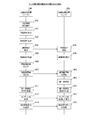
- sequence chart which shows the example of a communication process between each apparatus which comprises the communication system 60 in 4th Embodiment of this technique.
- sequence chart which shows the example of a communication process between each apparatus which comprises the communication system 60 in 4th Embodiment of this technique.
- composition of communications system 70 in a 4th embodiment of this art.
- First embodiment communication control: an example of performing wireless connection authentication using authentication key information output from a sink device and authentication key information input to a source device
- Second embodiment communication control: an example in which another source device connection request is made in a state where wireless communication is performed between the source device and the sink device
- Third embodiment communication control: an example of switching the connection state of a source device at an appropriate timing
- Fourth embodiment communication control: an example in which authentication is performed using authentication key information generated by a device other than the source device and the sink device
- FIG. 1 is a diagram illustrating a configuration example of a communication system 10 according to the first embodiment of the present technology.
- FIG. 1 shows an example of a system configuration when two information processing apparatuses (information processing apparatuses 100 and 200) are directly wirelessly connected.
- the communication system 10 includes information processing apparatuses 100 and 200.
- the information processing apparatus 100 is, for example, an electronic device having a wireless communication function (for example, a wireless communication device (for example, a small portable device) such as a mobile phone, a smartphone, or a tablet terminal).
- the information processing apparatus 200 is, for example, an electronic device having a wireless communication function (for example, a video viewing apparatus (for example, a large television) that outputs images and sounds).
- the information processing apparatuses 100 and 200 are wireless communication apparatuses compliant with IEEE (Institute of Electrical and Electronics Electronics) 802.11 specifications.
- the information processing apparatuses 100 and 200 can exchange various types of information using a wireless communication function.
- a wireless LAN Local Area Network
- Wi-Fi registered trademark
- TDLS Tunnelneled Direct Link Link Setup
- Wi-Fi CERTIFIED Miracast can be used as short-range wireless AV (Audio Visual) transmission communication used in the communication system 10.
- Wi-Fi CERTIFIED Miracast uses Wi-Fi Direct and TDLS technologies to transmit audio and display video that is played on one terminal to another terminal, and the other terminal can transmit the audio, This is a mirroring technology that outputs video data.
- wireless communication used in the communication system 10 for example, Bluetooth (registered trademark) (IEEE802.15.1), ZigBee (IEEE802.15.4), infrared communication, or the like can be used. Further, as wireless communication used in the communication system 10, for example, a public network (for example, 3G (3rd generation), LTE (Long terminal evolution)) may be used.
- the information processing apparatus 100 is a source device and the information processing apparatus 200 is a sink device
- the source device means a transmission-side information processing device that transmits content
- the sink device means a reception-side information processing device that receives and outputs content
- the source device is an information processing apparatus (for example, a small device) in which content (user content) such as a still image and a moving image is stored.
- the sink device is an information processing apparatus (for example, a large device) that outputs (for example, image display or audio output) content received using wireless communication.
- the information processing apparatus 100 can transmit content (for example, image data and audio data) stored in the memory 130 (shown in FIG. 2) to the information processing apparatus 200 using wireless communication.
- the information processing apparatus 100 can transmit content to the information processing apparatus 200 using Wi-Fi CERTIFIED Miracast.
- the information processing apparatus 100 is an example of a first information processing apparatus described in the claims.
- the information processing apparatus 200 displays an image based on the content transmitted from the information processing apparatus 100 on the display unit 242. Further, the information processing apparatus 200 outputs a sound based on the content transmitted from the information processing apparatus 100 from the sound output unit 272 (shown in FIG. 3).
- the information processing device 200 is an example of a second information processing device described in the claims.
- a photograph or a moving image is displayed on a device (for example, a large screen display device (large device) such as a large television) having a large display unit.
- a device for example, a large screen display device (large device) such as a large television
- information (contents) of a photograph or a moving image is transmitted from a small device at hand to a large device and displayed by using wireless communication (for example, wireless LAN).
- Authorization authentication that a source device and a sink device may be paired and information from the source device may be displayed on a specific sink device ( (Authorization) is required.
- pairing and authentication can be realized by giving the same key information to both at the first time.
- This method is realized by, for example, Bluetooth pairing.
- the same key information is, for example, a PIN code (PersonalsonIdentification Number Code).
- the owner of the sink device is not an individual (for example, a TV set in a hotel room is a sink device).
- the key information input method of the sink device for example, television
- a method of performing authentication by using a proximity wireless communication function other than the wireless communication function (for example, wireless LAN) used for content communication instead of inputting the same key information (for example, PIN code) has been proposed. Yes.
- the source device and the sink device need to have a plurality of wireless communication functions (for example, wireless LAN, proximity wireless communication function), the cost of the apparatus may increase.
- a single wireless communication function for example, wireless LAN
- sink devices for example, a television set in each room of a hotel
- a sink device installed in a room adjacent to the room where the user is staying is assumed to be the radio wave reachable range of the source device owned by the user.
- a key may be exchanged by mistake with a sink device other than the sink device installed in the room where the user is staying (for example, a television installed in an adjacent room).
- a sink device other than the sink device installed in the room where the user is staying for example, a television installed in an adjacent room.
- the authentication key information is displayed on the sink device that the user who owns the source device desires to use, and pairing and authentication are performed between the source device and the sink device using the authentication key information.
- authentication key information for example, a cat image 12 in which a key is imaged
- FIG. 1 A diagram illustrating an example of performing For example, as shown in FIG. 1, authentication key information (for example, a cat image 12 in which a key is imaged) is displayed on the display unit 242 of the information processing apparatus 200 that the user 11 who owns the information processing apparatus 100 desires to use. Let In this case, pairing and authentication are performed between the information processing apparatus 100 (source device) and the information processing apparatus 200 (sink device) using the authentication key information (cat image 12) displayed on the display unit 242.
- the user 11 who has seen the authentication key information (cat image 12) displayed on the display unit 242 uses the operation reception unit 152 to input the authentication key information (for example, “cat”). Thereby, pairing and authentication can be appropriately performed between the information processing apparatus 100 and the information processing apparatus 200.
- the authentication key information for example, “cat”.
- the authentication key information (cat image 12) is displayed on the information processing apparatus 200 (sink device) that the user 11 desires to use, and the authentication key information (cat image 12) is displayed on the user 11 (or information processing apparatus). 100 (source device)). Accordingly, the user 11 can reliably recognize that the information processing apparatus 200 (sink device) is an output destination of information (content). Further, authentication key information is transmitted from the information processing apparatus 100 (source device) owned by the user 11 to the information processing apparatus 200 (sink device) desired to be used, and paired with the sink device intended by the user 11 And can perform authentication.
- authentication key information information that can be confirmed to be unique within a certain range (within a predetermined range based on the position where the information processing apparatus 100 (source device) exists) can be used.
- the device address of the source device or sink device may be used.
- the authentication key information is changed every time pairing and authentication are performed.
- it can be sequentially changed to other animals (for example, dogs, horses, cows, goats), symbols, characters, and the like.
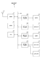
- FIG. 2 is a block diagram illustrating an internal configuration example of the information processing apparatus 100 according to the first embodiment of the present technology.
- the information processing apparatus 100 includes an antenna 111, a communication unit 112, a control unit 120, a memory 130, a display information input / output unit 141, and a display unit 142.
- the information processing apparatus 100 includes an operation information input / output unit 151, an operation reception unit 152, an imaging information input / output unit 161, an imaging unit 162, an audio information input / output unit 171, an audio input unit 172, and an audio. And an output unit 173. These units are connected via a bus 180.
- the communication unit 112 is a module (for example, a modem) for transmitting and receiving radio waves via the antenna 111.
- the communication unit 112 can perform wireless communication by a wireless LAN (Local Area Network).
- the communication unit 112 uses the wireless communication to control each piece of information (authentication key information, key image, content) with other wireless communication devices that exist within a predetermined range using wireless communication.
- the predetermined range is a range based on the position of the information processing apparatus 100, for example, and means a range in which the communication unit 112 can transmit and receive data using wireless communication.
- the other wireless communication device existing within the predetermined range is, for example, a wireless communication device that exists in the vicinity of the information processing device 100, and transmits and receives data to and from the information processing device 100 using wireless communication. It is assumed that the wireless communication apparatus can perform the above. Note that wireless communication may be performed using a wireless communication function other than the wireless LAN described above.
- the control unit 120 controls each unit of the information processing apparatus 100 based on a control program stored in the memory 130. For example, the control unit 120 performs signal processing of transmitted / received information.
- the control unit 120 is realized by a CPU (Central Processing Unit), for example.
- the memory 130 is a memory for storing various information.
- the memory 130 stores various information (for example, a control program) necessary for the information processing apparatus 100 to perform a desired operation. Further, the memory 130 stores various contents such as contents to be reproduced (for example, moving picture contents and still picture contents).
- the control unit 120 processes information read from the memory 130, a signal input from the operation receiving unit 152, and the like, and transmits data to be actually transmitted. Generate a chunk (transmit packet). Subsequently, the control unit 120 outputs the generated transmission packet to the communication unit 112.
- the communication unit 112 converts the transmission packet into a format of a communication method for actual transmission, and then transmits the converted transmission packet from the antenna 111 to the outside.
- the communication unit 112 when receiving data using wireless communication, extracts a received packet from a radio signal received via the antenna 111 by signal processing performed by a receiver in the communication unit 112. To do. Then, the control unit 120 interprets the extracted received packet. As a result of this interpretation, when it is determined that the data is to be held, the control unit 120 writes the data in the memory 130.
- control unit 120 can provide various contents stored in the memory 130 to other wireless communication devices using wireless communication.
- the display unit 142 is a display unit that displays various types of information (for example, the display screen shown in FIG. 9) supplied via the display information input / output unit 141 based on the control of the control unit 120.
- a display panel such as an organic EL (Electro Luminescence) panel or an LCD (Liquid Crystal Display) panel can be used.
- the size (display size) of the display unit 142 is often about 4 inches to 5 inches, for example.
- the size (display size) of the display unit 142 is often about 7 inches to 10 inches, for example.
- the operation accepting unit 152 is an operation accepting unit that accepts an operation input performed by the user, and outputs operation information corresponding to the accepted operation input to the control unit 120 via the operation information input / output unit 151.
- the operation reception unit 152 is realized by, for example, a touch panel, a keyboard (or a virtual keyboard on the touch panel), and a mouse. Note that the operation reception unit 152 and the display unit 142 can be integrally configured using a touch panel that allows a user to input an operation by touching or approaching the finger with the display surface.
- the imaging unit 162 captures a subject and generates image data (still image data, moving image data) based on the control of the control unit 120.
- the imaging information input / output unit 161 uses the generated image data. Is output to the control unit 120. Further, the control unit 120 causes the memory 130 to record the image data generated in this way as image content (still image content, moving image content).
- the imaging unit 162 captures a key image and generates a key image.
- the imaging unit 162 includes, for example, an optical system (a plurality of lenses), an imaging element, and a signal processing unit. For example, a charge coupled device (CCD) or a complementary metal oxide semiconductor (CMOS) can be used as the imaging device.
- CCD charge coupled device
- CMOS complementary metal oxide semiconductor
- the voice input unit 172 is a voice input unit (for example, a microphone) that acquires sounds around the information processing apparatus 100, and controls information (voice information) about the acquired sounds via the voice information input / output unit 171. To the unit 120.
- a voice input unit for example, a microphone
- the sound output unit 173 is a sound output unit (for example, a speaker) that outputs various sounds supplied via the sound information input / output unit 171 based on the control of the control unit 120.
- FIG. 3 is a block diagram illustrating an internal configuration example of the information processing apparatus 200 according to the first embodiment of the present technology.
- the information processing apparatus 200 includes an antenna 211, a communication unit 212, a control unit 220, a memory 230, a display information input / output unit 241, and a display unit 242.
- the information processing apparatus 200 includes an operation information input / output unit 251, an operation reception unit 252, a remote controller information input / output unit 261, an audio information input / output unit 271, and an audio output unit 272. These units are connected through a bus 280.
- the information processing apparatus 200 is an information processing apparatus in which the size of the display unit 242 (display size) is larger than the display size of the information processing apparatus 100, for example.
- the antenna 211, the communication unit 212, the display information input / output unit 241, the display unit 242, the audio information input / output unit 271, and the audio output unit 272 correspond to the components having the same names shown in FIG. For this reason, the detailed description here is abbreviate
- the display unit 242 displays an image based on the image data transmitted from the information processing apparatus 100.
- the audio output unit 272 outputs audio based on the audio data transmitted from the information processing apparatus 100.
- the display unit 242 and the audio output unit 272 are examples of the output unit described in the claims.
- the control unit 220 controls each unit of the information processing apparatus 100 based on a control program stored in the memory 230. For example, the control unit 220 performs signal processing of transmitted / received information.
- the control unit 220 is realized by a CPU, for example.
- the memory 230 is a memory for storing various information.
- the memory 230 stores various information (for example, a control program) necessary for the information processing apparatus 200 to perform a desired operation. Further, the memory 230 stores various contents such as contents to be reproduced (for example, moving picture contents and still picture contents).
- control unit 220 can output (image display, audio output) various contents provided from other wireless communication devices using wireless communication.
- the control unit 220 allows the information processing apparatus 100 to wirelessly connect to the information processing apparatus 200 for performing data transmission from the information processing apparatus 100 to the information processing apparatus 200 using wireless communication.
- the authentication key information is displayed on the display unit 242.
- the cat image 12 is displayed on the display unit 242 as the authentication key information.
- the control unit 220 determines whether to allow the information processing apparatus 100 to perform the wireless connection based on the authentication key information input to the information processing apparatus 100 and the authentication key information displayed on the display unit 242. decide. For example, when it is determined that the authentication key information input to the information processing apparatus 100 matches the authentication key information output to the display unit 242, the control unit 220 permits the information processing apparatus 100 to perform wireless connection. Then decide.
- control unit 220 displays an image based on the content transmitted from the information processing apparatus 100 on the display unit 242, and the audio based on the content Is output from the audio output unit 272.
- the operation accepting unit 252 is an operation accepting unit that accepts an operation input performed by the user, and outputs operation information corresponding to the accepted operation input to the control unit 220 via the operation information input / output unit 251.
- the operation reception unit 252 is realized by an operation member such as a button (for example, a power button or a setting button), for example.
- a button for example, a power button or a setting button
- the operation receiving unit 252 and the display unit 242 can be integrally configured using a touch panel that allows a user to input an operation by touching or approaching the finger with the display surface.
- the remote controller 262 is a remote controller for remotely operating the information processing apparatus 200 from a remote location, and transmits an operation signal (remote controller information) corresponding to an operation input by the user to the remote controller information input / output unit 261.
- an operation signal remote controller information
- an infrared signal can be used as an output signal of the remote controller 262.
- the remote controller information input / output unit 261 inputs and outputs operation signals (remote controller information) from the remote controller 262. For example, when receiving an operation signal from the remote controller 262, the remote controller information input / output unit 261 supplies the received operation signal to the control unit 220.
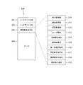
- FIG. 4 is a diagram schematically illustrating a format example of the information 300 communicated between the devices included in the communication system 10 according to the first embodiment of the present technology. That is, FIG. 4 shows a format example of information 300 communicated between the source device and the sink device.
- the information 300 communicated between the source device and the sink device includes a source device ID 301, a sink device ID 302, an information element identifier 303, and data 304.
- the source device ID 301 is identification information (Identification Number) for identifying the source device.
- the sink device ID 302 is identification information for identifying the sink device.
- a device-specific ID for example, MAC (Media Access Control) address
- MAC Media Access Control
- the information element identifier 303 is information for identifying what information is to be transmitted.
- the information element identifier 303 stores information for identifying any of the display key information 310 to the rejection reason notification 319.
- the display key information 310 is information indicating that the content of the data 304 is a key code for displaying a key image on the sink device.
- This key code is, for example, identification information for specifying a key image to be displayed on the sink device. That is, this key code is information for the sink device to convert the key into image information.
- the key code for specifying the cat image is “001”
- the key code for specifying the dog image is “002”.
- the key image to be displayed on the sink device is a cat image (for example, the cat image 12 shown in FIG. 1)
- the key code “001” for specifying the cat image is the data 304.
- the key image information 311 is information indicating that the content of the data 304 is a key image displayed on the sink device. That is, when the key image information 311 is stored in the information element identifier 303, the key image (key image data) is stored in the data 304.
- the content of the data 304 is a key code transmitted from the source device to the sink device (a key code transmitted from the source device by reading the key image displayed on the sink device on the source device side). It is information indicating that there is. That is, when the authentication key information 312 is stored in the information element identifier 303, a key code (for example, a key code “001” for specifying a cat image) is stored in the data 304.
- a key code for example, a key code “001” for specifying a cat image
- User information 313 is information indicating that the content of the data 304 is data (for example, user content (still image content, moving image content)) transmitted from the source device to the sink device after authentication. For example, when user information 313 is stored in the information element identifier 303, user content (still image content, moving image content) is stored in the data 304.
- the key image information 311 and the user information 313 are the same in that the content of the data 304 is information indicating that it is image information.
- the user information 313 is information exchanged only between the source device and the sink device that have been authenticated.
- the key image information 311 is different in that it is information exchanged between the source device and the sink device before the authentication is completed. That is, the sink device needs to display only the image corresponding to the key image information 311 on the display unit even in a state before authentication.
- connection release request 314 is information indicating that the content of the data 304 is a request for releasing the connection state between the source device and the sink device (connection release request). That is, when the connection release request 314 is stored in the information element identifier 303, information related to the connection release request is stored in the data 304.
- the key information request 315 is information indicating that the content of the data 304 is a key information transmission request for the source device to request the key information providing server to transmit authentication key information. That is, when the key information request 315 is stored in the information element identifier 303, information related to the key information transmission request is stored in the data 304.
- the key information providing server will be described in a fourth embodiment of the present technology.
- the key match confirmation result 316 is information indicating that the content of the data 304 is a key authentication (key match confirmation) result (key match confirmation result). That is, when the key match confirmation result 316 is stored in the information element identifier 303, the key match confirmation result (match or mismatch) is stored in the data 304.
- the authentication key generation request 317 is information indicating that the content of the data 304 is an authentication key generation request for requesting the sink device to generate an authentication key. That is, when the authentication key generation request 317 is stored in the information element identifier 303, information related to the authentication key generation request is stored in the data 304.
- the key information display notification 318 is information indicating that the content of the data 304 is a notification (key information display notification) to the source device that the authentication key information is displayed on the sink device. That is, when the key information display notification 318 is stored in the information element identifier 303, information related to the key information display notification is stored in the data 304.
- the rejection reason notification 319 is information indicating that the content of the data 304 is the reason (a rejection reason notification transmitted from the sink device to the source device) when the connection request from the source device is rejected. That is, when the rejection reason notification 319 is stored in the information element identifier 303, the data 304 stores information related to the rejection reason notification.
- the connection request is a request for wireless connection to the sink device for performing data transmission from the source device to the sink device using wireless communication. That is, the connection request can be grasped as a request for causing the sink device to output authentication key information for permitting the wireless connection to the source device.
- Data 304 is data corresponding to information stored in the information element identifier 303.
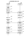
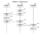
- FIG. 5 is a sequence chart illustrating an example of communication processing between devices included in the communication system 10 according to the first embodiment of the present technology.
- FIG. 5 shows an example of communication processing when the user 11 performs an authentication start instruction operation in the state shown in FIG.
- FIG. 5 shows an example of communication processing when the user 11 performs an authentication start instruction operation in the sink device (information processing apparatus 200) and generates an authentication key on the sink device (information processing apparatus 200) side.
- the user 11 performs an authentication start instruction operation using the operation reception unit 252 or the remote controller 262 of the information processing apparatus 200 on the sink side (401).
- an operation member for example, a setting button for performing an authentication start instruction operation is pressed (401).
- the control unit 220 of the sink-side information processing device 200 uses the authentication start instruction operation as a trigger for authentication.
- An authentication key used for processing is generated (402). For example, in the example shown in FIG. 1, “cat (cat)” is generated as a key.
- the control unit 220 of the sink-side information processing device 200 converts the generated authentication key into image information to generate a key image (403).
- This key image is an image corresponding to the generated authentication key, and is an image for allowing the user to visually recognize the generated authentication key.
- a cat image (cat image 12) corresponding to the key “cat (cat)” is generated as the key image.
- the control unit 220 of the information processing apparatus 200 on the sink side displays the generated key image on the display unit 242 (404).
- the cat image 12 is displayed on the display unit 242 as the key image.
- the key image is displayed on the display unit 242 so that the user 11 can visually recognize the key image (405).
- the user 11 can recognize that the key is “cat”.
- the user 11 After visually recognizing the key image (for example, cat (cat)) displayed on the display unit 242 (405), the user 11 obtains the authentication key information corresponding to the key image from the information processing device on the source side. Input is made at the operation reception unit 152 of 100 (406). For example, as shown in FIG. 1, when the cat image 12 is displayed on the display unit 242 as the key image, the user 11 inputs “cat” as the authentication key information.
- an input method for example, when katakana input is specified
- a character for example, katakana
- authentication key information corresponding to the key image may be input by voice.
- the voice “cat” of the authentication key information may be input using the voice input unit 172 of the information processing apparatus 100 on the source side, and the authentication key information “cat” may be acquired based on this voice.
- the control unit 120 of the information processing apparatus 100 on the source side transmits the input authentication key information to the information processing apparatus 200 on the sink side using wireless communication (407, 408).
- the identification information of the information processing apparatus 100 is stored in the source device ID 301 (shown in FIG. 4) included in the information to be transmitted, and the information processing apparatus 200 is stored in the sink device ID 302 (shown in FIG. 4). Is stored.
- the authentication key information 312 is stored in the information element identifier 303 (shown in FIG. 4), and the input authentication key information is stored in the data 304 (shown in FIG. 4).
- the identification information of the information processing apparatus 100 is stored in the source device ID 301 (shown in FIG. 4), and the identification of the information processing apparatus 200 is stored in the sink device ID 302 (shown in FIG. 4). Information shall be stored.
- the control unit 220 of the sink-side information processing device 200 is stored in the generated authentication key information and the received authentication key information (data 304 (shown in FIG. 4)). It is confirmed whether or not (authentication key information) matches (409). That is, it is confirmed whether or not the authentication key information generated using the authentication start instruction operation as a trigger matches the authentication key information received after the key image corresponding to the authentication key information is displayed on the display unit 242. (409).
- the control unit 220 of the sink-side information processing device 200 transmits a result of authentication key information matching confirmation (key matching confirmation result) to the source-side information processing device 100 (410, 411).
- a key matching confirmation result 316 is stored in the information element identifier 303 (shown in FIG. 4) included in the information to be transmitted, and a key matching confirmation result (matching or matching) is stored in the data 304 (shown in FIG. 4). Is stored.
- a key match confirmation result (match) indicating that the keys match is transmitted from the sink-side information processing device 200 to the source-side information processing device 100 (410, 411). That is, information indicating that the authentication is successful (a key match confirmation result) is transmitted from the sink-side information processing device 200 to the source-side information processing device 100 (410, 411).
- the information processing apparatus 100 on the source side and the information processing apparatus 200 on the sink side are connected. Accordingly, the content transmitted from the source-side information processing apparatus 100 to the sink-side information processing apparatus 200 can be output from the sink-side information processing apparatus 200 (412 and 413). That is, after the key matching confirmation result indicating that the authentication is successful is transmitted to the information processing apparatus 100 on the source side, the content transmitted by the information processing apparatus 100 on the source side is output from the information processing apparatus 200 on the sink side. (412, 413).
- the content stored in the memory 130 of the source-side information processing apparatus 100 can be transmitted from the source-side information processing apparatus 100 to the sink-side information processing apparatus 200 using wireless communication (412). 413).
- the sink-side information processing device 200 can display the received content on the display unit 242 (413).
- the control unit 120 of the source-side information processing apparatus 100 transmits a connection release request to the sink-side information processing apparatus 200 ( 414, 415).
- a connection release request 314 is stored in the information element identifier 303 (shown in FIG. 4) included in the information to be transmitted, and information on the connection release request is stored in the data 304 (shown in FIG. 4).
- connection state between the information processing apparatus 100 on the source side and the information processing apparatus 200 on the sink side can be terminated.
- a key match confirmation result (mismatch) indicating that the keys do not match is transmitted to the information processing apparatus 100 on the source side (410, 411). That is, information indicating that the authentication has failed (key match confirmation result) is transmitted from the sink-side information processing device 200 to the source-side information processing device 100 (410, 411).
- the key element confirmation result 316 is stored in the information element identifier 303 (shown in FIG. 4) included in the information to be transmitted, and the key agreement confirmation result (non-match) is stored in the data 304 (shown in FIG. 4). Is stored.
- notification information indicating that the authentication has failed can be output (image display, audio output) from at least one of the information processing apparatus 100 on the source side and the information processing apparatus 200 on the sink side.
- FIG. 5 shows an example in which the user 11 visually recognizes the key image displayed on the display unit 242 of the information processing apparatus 200 on the sink side and inputs authentication key information corresponding to the key image.
- the authentication key information may be input to the information processing apparatus 100 on the source side.
- the imaging unit 162 of the source-side information processing device 100 captures the key image displayed on the display unit 242 of the sink-side information processing device 200 and acquires the key image. Then, the control unit 120 of the information processing apparatus 100 on the source side acquires authentication key information based on the acquired key image, and transmits the acquired authentication key information to the information processing apparatus 200 on the sink side. Can do.
- control unit 120 of the information processing apparatus 100 on the source side can use the key image acquired by the imaging unit 162 as authentication key information and transmit the authentication key information to the information processing apparatus 200 on the sink side.
- the sink-side information processing device 200 confirms the match between the generated key image and the received key image. In this case, for example, matching can be confirmed by matching processing between images.
- FIG 5 shows an example in which the key image (cat image 12) that allows the user to grasp the image is displayed, but a key image that cannot grasp the image may be displayed. In this case, the user can acquire authentication key information using the key image.
- characters, symbols, numbers, etc. may be displayed, recognized by a recognition technique, and authentication key information may be acquired based on the recognition result.
- An example of this display is shown in FIG.
- a multi-dimensional code (for example, a one-dimensional code, a two-dimensional code, a three-dimensional code) is displayed, recognized by a recognition technique, and authentication key information is acquired based on the recognition result. Good.
- a recognition technique for example, a two-dimensional code, a three-dimensional code
- a watermark (digital watermark) may be displayed, and authentication key information may be acquired using this watermark.
- An example of this display is shown in FIG.
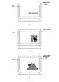
- FIG. 6 is a diagram illustrating a display example of the key image displayed on the display unit 242 of the information processing device 200 according to the first embodiment of the present technology.
- Fig. 6a shows an example in which characters, symbols, numbers, symbols (pictograms), etc. are displayed as key images.
- the user visually recognizes the key image (17KM809) displayed on the display unit 242 and inputs the key image (17KM809) to the operation reception unit 152 of the information processing apparatus 100, thereby processing the information.
- the apparatus 100 can acquire authentication key information. Further, as described above, the authentication key information (17KM809) may be recognized by a recognition technique, and the authentication key information may be acquired based on the recognition result.
- FIG. 6b shows an example in which a two-dimensional code (for example, a QR code (registered trademark) (Quick Response code)) is displayed as a key image.
- a two-dimensional code for example, a QR code (registered trademark) (Quick Response code)
- the QR code is a matrix type two-dimensional code in which small rectangles (including “round” -shaped rectangles arranged at three corners) are arranged vertically and horizontally according to a predetermined rule. Further, by imaging and reading the QR code, various information (accompanying information) corresponding to each rectangle arranged in the QR code can be acquired.
- the imaging unit 162 images the key image (QR code) displayed on the display unit 242, and the control unit 120 analyzes the key image (QR code) generated by the imaging. Obtain valid information (authentication key information).
- a bar code may be displayed and used instead of the QR code.
- other multidimensional codes may be displayed and used.
- FIG. 6c shows a display example of an image (Mt. Fuji at sunrise) in which a watermark (digital watermark) as a key image is embedded.
- a watermark is a digital watermark embedded in an image to be displayed.
- an example in which authentication key information is embedded in an image to be displayed is shown.
- watermarks there are mainly two types of watermarks: a perceptible watermark (visible watermark) and a difficult to perceive watermark (invisible watermark).
- the authentication key information may be input using the posture (for example, vibration or tilt) of the information processing apparatus 100 on the source side.
- a sensor for example, a gyro sensor or an acceleration sensor
- the posture is provided in the information processing apparatus 100 on the source side.
- “shake the information processing apparatus 100 three times” as the authentication key information is displayed on the display unit 242 of the information processing apparatus 200 on the sink side.
- the sensor detects the three vibrations.
- the control unit 120 of the information processing apparatus 100 on the source side can acquire authentication key information (three times of vibrations).
- FIG. 6 shows an example in which the authentication key information is displayed relatively large for ease of explanation, but the authentication key information is displayed in a corner (for example, lower left, lower right) of the display screen of the display unit 242. It is preferable to do.
- the authentication key information every time it is displayed.
- the key image shown in FIG. 1 image obtained by imaging the authentication key information
- the characters shown in FIG. 6A, the QR code shown in FIG. 6B, and the watermark shown in FIG. 6C are displayed in order. be able to.
- the contents of the same type of authentication key information may be sequentially changed and displayed.
- animals eg, cats, dogs, horses, rabbits
- vehicles eg, cars, trains, motorcycles
- the authentication key information may be changed and displayed according to the user's preference.
- a user who likes a car may display various types of cars as authentication key information, and input the displayed car model name as authentication key information.
- user preferences can be acquired based on user information stored in an information processing apparatus owned by the user, for example.
- an example in which authentication key information (or key image) is generated every time an authentication start instruction operation is performed is shown.
- the authentication key information (or key image) is stored in advance in the apparatus, and each time the authentication start instruction operation is performed, the stored authentication key information (or key image) is selected sequentially. You may make it use.
- the stored authentication key information (or key image) may be selected according to a predetermined order, or may be selected randomly.
- authentication key information shown in FIGS. 1 and 6 is an example, and the present invention is not limited to this. That is, authentication key information other than the authentication key information shown in FIGS. 1 and 6 may be displayed and used as authentication key information.
- FIG. 5 shows an example in which the authentication start instruction operation is performed in the sink-side information processing apparatus 200
- the authentication start instruction operation may be performed in the source-side information processing apparatus 100.
- FIGS. 7 shows an example in which the information processing apparatus on the source side generates an authentication key.
- FIG. 8 shows an example in which the information processing device on the source side generates a key image.
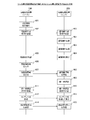
- FIG. 7 is a sequence chart illustrating an example of communication processing between devices included in the communication system 10 according to the first embodiment of the present technology. Note that the communication processing example shown in FIG. 7 is a modification of part of the communication processing shown in FIG. 5. Therefore, the same reference numerals are given to the parts common to the communication processing shown in FIG. A part of the description will be omitted.
- the user 11 performs an authentication start instruction operation in the operation reception unit 152 of the information processing apparatus 100 on the source side (421). For example, the user 11 performs a pressing operation on an operation member (for example, a touch panel or a keyboard) for performing an authentication start instruction operation (421).
- an operation member for example, a touch panel or a keyboard
- the control unit 120 of the information processing apparatus 100 on the source side uses the authentication start instruction operation as a trigger to perform authentication.
- An authentication key used for processing is generated (422). For example, in the example shown in FIG. 1, “cat (cat)” is generated as the authentication key.
- the control unit 120 of the information processing apparatus 100 on the source side transmits display key information for converting the generated authentication key to image information to the information processing apparatus 200 on the sink side (423, 424).
- the display key information 310 is stored in the information element identifier 303 (shown in FIG. 4) included in the information to be transmitted, and the data 304 (shown in FIG. 4) corresponds to the generated authentication key.
- Display key information (key code) to be stored is stored.
- the control unit 220 of the information processing apparatus 200 on the sink side converts the received display key information into image information to generate a key image (425). For example, in the example illustrated in FIG. 1, a cat image 12 corresponding to the key “cat (cat)” is generated.
- control unit 220 of the information processing apparatus 200 on the sink side displays the generated key image on the display unit 242 (426).
- the cat image 12 is displayed on the display unit 242 as the key image.
- the processing on the sink device side can be simplified and the processing on the sink device side can be reduced.
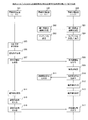
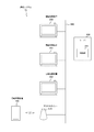
- FIG. 8 is a sequence chart illustrating an example of communication processing between the devices included in the communication system 10 according to the first embodiment of the present technology. Note that the communication processing example shown in FIG. 8 is a modification of a part of the communication processing shown in FIG. 5. Therefore, the same reference numerals are given to the parts common to the communication processing shown in FIG. A part of the description will be omitted.
- the user 11 performs an authentication start instruction operation in the operation reception unit 152 of the information processing apparatus 100 on the source side (431).
- the control unit 120 of the source information processing apparatus 100 uses the authentication start instruction operation as a trigger for authentication.
- An authentication key used for processing is generated (432).
- the control unit 120 of the information processing apparatus 100 on the source side converts the generated authentication key into image information to generate a key image (433).
- a cat image 12 corresponding to the key “cat (cat)” is generated as the key image.
- the control unit 120 of the information processing apparatus 100 on the source side transmits the generated key image to the information processing apparatus 200 on the sink side (434, 435).
- the key image information 311 is stored in the information element identifier 303 (shown in FIG. 4) included in the information to be transmitted, and the generated key image (key key) is stored in the data 304 (shown in FIG. 4). Image data of the image) is stored.
- the control unit 220 of the information processing apparatus 200 on the sink side displays the received key image on the display unit 242 (436).
- the cat image 12 is displayed on the display unit 242.
- the processing on the sink device side can be further simplified, and the processing on the sink device side can be further reduced.
- the source information processing apparatus 100 grasps the authentication key displayed on the sink information processing apparatus 200. Will be. Therefore, in such a case, when inputting the authentication key information, for example, a plurality of key images (for example, a dog image, a cow image, a pig image) are displayed on the display unit 142 of the information processing apparatus 100 on the source side. Image) can be displayed. Then, a key image (for example, cat image 12) displayed on the display unit 242 of the sink-side information processing device 200 is selected by a user operation from a plurality of key images displayed on the display unit 142. . Thus, the authentication key information input operation can be performed only by the selection operation by the user.
- a plurality of key images for example, a dog image, a cow image, a pig image
- a key image for example, cat image 12
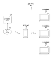
- FIG. 9 is a diagram illustrating a configuration example of the communication system 20 according to the first embodiment of the present technology.
- FIG. 9 illustrates an example of a hotel in which information processing devices 200 to 202 (corresponding to the sink-side information processing device 200 shown in FIG. 1) are installed in each room (room 210 to room 212).
- information processing devices 200 to 202 corresponding to the sink-side information processing device 200 shown in FIG. 1 are installed in each room (room 210 to room 212).
- room 210 to room 212 room 210 to room 2112.
- FIG. 9 a case where a user who possesses the information processing apparatus 100 stays in room 211 of this hotel will be described as an example.
- FIG. 1, FIG. 5, FIG. 7, FIG. 8 and the like show examples in which information is exchanged between one source device and one sink device.
- a user who owns the information processing apparatus 100 stays in a hotel where the information processing apparatuses 200 to 202 are installed in each room (room 210 to room 212). To do.
- the information stored in the information processing apparatus 100 is wirelessly connected to the information processing apparatus 100 possessed by the user and the information processing apparatus 201 installed in the room 211 where the user is staying. Can be displayed on the information processing apparatus 201.
- wireless connection is possible between the information processing apparatus 100 and the information processing apparatuses 200 and 202 installed in a room (room 210 and room 212) other than the room 211 where the user is staying. Is done. For example, as illustrated in FIGS. 7 and 8, when information (display key information, key image) generated by the information processing apparatus 100 on the source side is transmitted, the information is transmitted to the information processing apparatuses 201 and 202 other than the information processing apparatus 201. It is also assumed that In this case, the content stored in the information processing apparatus 100 may not be displayed properly on the information processing apparatus 201.
- FIG. 9 shows an example of selecting an information processing apparatus to be wirelessly connected by a selection operation by a user.
- the first display key information (or key image information) is transmitted.
- a plurality of sink devices (sink-side information processing devices 200 to 202) detected by the source-side information processing device 100 are displayed on the display unit 142 of the source-side information processing device 100.
- selection buttons 321 to 323 corresponding to the information processing devices 200 to 202 installed in each room (room 210 to room 212) are displayed.
- the user performs an authentication start instruction operation (421 shown in FIG. 7 and 431 shown in FIG. 8) by pressing the selection button 322 corresponding to the desired information processing apparatus 201 among the selection buttons 321 to 323. It can be performed.
- An authentication key is generated by this authentication start instruction operation, and display key information (or key image information) is transmitted to the information processing apparatus 201 corresponding to the selected selection button (423 (or FIG. 8 shown in FIG. 7)). 434)).
- control unit 120 of the information processing apparatus 100 on the source side causes the display unit 142 to display information regarding a plurality of sink devices. Then, the control unit 120 transmits information related to the sink device selected by the user operation from among the plurality of displayed sink devices to the selected sink device.
- control unit 220 of the sink-side information processing device 200 allows the wireless connection to the source-side information processing device 100 based on information about the selected sink device (sink-side information processing device 201).
- the authentication key information is displayed on the display unit 242.
- the control unit 220 authenticates the information processing apparatus 100 on the source side to the wireless connection to the sink device (sink side information processing apparatus 201) selected by the user operation from among the plurality of sink devices.
- Information is displayed on the information processing apparatus 201 on the sink side.
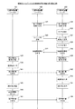
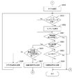
- FIG. 10 is a sequence chart illustrating an example of communication processing between devices included in the communication system 10 according to the first embodiment of the present technology.
- the communication processing example shown in FIG. 10 is a modification of part of the communication processing shown in FIG. 8. Therefore, the same reference numerals are given to parts common to the communication processing shown in FIG. A part of the description will be omitted.
- the user 11 After viewing the key image (for example, cat image 12) displayed on the display unit 242 of the information processing apparatus 200 on the sink side (405), the user 11 obtains the authentication key information corresponding to the key image on the source side. Input is made at the operation reception unit 152 of the information processing apparatus 100 (406).
- the key image for example, cat image 12
- the user 11 After viewing the key image (for example, cat image 12) displayed on the display unit 242 of the information processing apparatus 200 on the sink side (405), the user 11 obtains the authentication key information corresponding to the key image on the source side. Input is made at the operation reception unit 152 of the information processing apparatus 100 (406).
- the control unit 120 of the information processing apparatus 100 on the source side checks whether or not the generated authentication key information matches the input authentication key information (441). That is, whether the authentication key information generated using the authentication start instruction operation as a trigger matches the authentication key information input after the key image corresponding to the authentication key information is transmitted to the information processing apparatus 200 on the sink side. Is confirmed (441).
- the control unit 120 of the information processing apparatus 100 on the source side transmits the result of matching confirmation of the authentication key information (key matching confirmation result) to the information processing apparatus 200 on the sink side (442, 443).
- a key matching confirmation result 316 is stored in the information element identifier 303 (shown in FIG. 4) included in the information to be transmitted, and a key matching confirmation result (matching or matching) is stored in the data 304 (shown in FIG. 4). Is stored.
- the information processing apparatus 200 on the sink side receives and outputs the content transmitted after receiving the key matching confirmation result (444, 445). That is, the content transmitted from the source-side information processing apparatus 100 to the sink-side information processing apparatus 200 can be output from the sink-side information processing apparatus 200 (444, 445).
- the control unit 120 of the source-side information processing apparatus 100 transmits a connection release request to the sink-side information processing apparatus 200 ( 446, 447).
- the information processing apparatus 200 on the sink side returns to the state before authentication.
- the control unit 120 of the source-side information processing device 100 provides authentication key information for permitting the source-side information processing device 100 to wirelessly connect to the sink-side information processing device 200. Control for outputting from the display unit 242 of the apparatus 200 is performed. Further, for example, the control unit 120 determines that the wireless connection is based on the authentication key information input to the source-side information processing apparatus 100 and the authentication key information output from the sink-side information processing apparatus 200. Information processing apparatus 100 is permitted. Then, the control unit 120 transmits the determination result (key match confirmation result) to the sink-side information processing device 200 using wireless communication.
- the processing on the sink device side can be further simplified, and the processing on the sink device side can be further reduced.
- FIG. 11 is a sequence chart illustrating an example of communication processing between devices included in the communication system 10 according to the first embodiment of the present technology. Note that the communication processing example shown in FIG. 11 is a modification of a part of the communication processing shown in FIG. 5, and therefore, parts common to the communication processing shown in FIG. A part of the description will be omitted.
- the user 11 performs an authentication start instruction operation in the operation reception unit 152 of the information processing apparatus 100 on the source side (451).
- the control unit 120 of the information processing apparatus 100 on the source side uses the authentication start instruction operation as a trigger to send an authentication key generation request to the information on the sink side. It transmits to the processing apparatus 200 (452, 453).
- an authentication key generation request 317 is stored in the information element identifier 303 (shown in FIG. 4) included in the information to be transmitted, and data 304 (shown in FIG. 4) contains information on the authentication key generation request. Is stored.
- the control unit 220 of the sink-side information processing device 200 When the authentication key generation request is received (453), the control unit 220 of the sink-side information processing device 200 generates an authentication key to be used when performing authentication processing, triggered by the reception of the authentication key generation request (402). .
- FIG. 12 is a sequence chart illustrating an example of communication processing between devices included in the communication system 10 according to the first embodiment of the present technology.
- the communication processing example shown in FIG. 12 is a modification of part of the communication processing shown in FIG. 5, FIG. 7, FIG. 8, FIG. 10, and FIG. The illustration and description thereof are omitted.
- the control unit 220 of the sink-side information processing device 200 transmits a key information display notification to the source-side information processing device 100. (462, 463).
- a key information display notification 318 is stored in the information element identifier 303 (shown in FIG. 4) included in the information to be transmitted, and information related to the key information display notification is stored in the data 304 (shown in FIG. 4). Is stored.
- the control unit 120 of the information processing apparatus 100 on the source side When the key information display notification is received (463), the control unit 120 of the information processing apparatus 100 on the source side outputs a key information display notification to prompt the user to start viewing (464).
- a key information display notification is output by display on the display unit 142 or voice output from the voice output unit 173 (464).
- a message “Please input the numerical value displayed on the TV” can be displayed on the display unit 142.
- the voice output unit 173 can output a voice message “Please input the numerical value displayed on the TV”.
- obtaining authentication key information for example, a perceptually difficult watermark
- a message “Please point the camera at the TV” is displayed on the display unit 142.
- the user can visually recognize the authentication key information (465) and input the authentication key information (466). If the authentication key information is a perceptually difficult watermark, the authentication key information is visually recognized by the imaging unit 162 of the information processing apparatus 100 on the source side (465).
- the key information display notification it is possible to notify the user that the key image is displayed on the information processing apparatus 200 on the sink side. Accordingly, it is possible to prompt the user to visually recognize the key image (or to capture an image by the imaging unit 162 of the information processing apparatus 100 on the source side).
- authentication key information for the authentication is output (for example, displayed or output by sound) from the sink device.
- the user of the source device or the source device itself recognizes the authentication key information and transmits the authentication key information from the source device to the sink device using wireless communication.
- the sink device can appropriately determine whether or not the source device and the sink device may be connected by collating the authentication key information. Accordingly, pairing and authentication as intended by the user can be easily performed. That is, connection processing can be appropriately performed when wireless communication is performed between the source device and the sink device.
- the sink device from which the authentication key information is output can be limited to the output from.
- the user information (content) of the source device (terminal at hand) held by the user can be output from an appropriate sink device intended by the user.
- the user information (content) of the source device (the terminal at hand) held by the user is erroneously output from the sink device that is not intended by the user (that is, the sink device that does not exist within the range visible to the user). Can be prevented.
- Second Embodiment> In the first embodiment of the present technology, the example in which wireless communication is performed between the source device and the sink device from when the authentication start instruction operation is performed until when a connection release request is made has been described. Here, it is assumed that the authentication start instruction operation is performed by another source device and the connection request is made from the other source device to the sink device after the authentication start instruction operation is performed until the connection release request is issued. Is done.
- the communication system according to the second embodiment of the present technology is substantially the same as the communication system 10 illustrated in FIG. For this reason, about the part which is common in the communication system 10, the same code
- FIG. 13 is a diagram illustrating a configuration example of the communication system 30 according to the second embodiment of the present technology.
- the communication system 30 includes information processing apparatuses 100, 101, and 200.
- the communication system 30 is obtained by adding a source-side information processing apparatus 101 to the communication system 10 shown in FIG.
- the internal configuration of the information processing apparatus 101 is the same as that of the information processing apparatus 100 shown in FIG. That is, FIG. 13 shows an example of a communication system including two source devices and one sink device.
- FIG. 14 is a sequence chart illustrating an example of a communication process between devices included in the communication system 30 according to the second embodiment of the present technology.
- FIG. 14 shows an example of communication processing when the user performs an authentication start instruction operation in the state shown in FIG.
- FIG. 14 illustrates an example of communication processing when the user performs an authentication start instruction operation on the source device (information processing apparatuses 100 and 101) and generates an authentication key on the source device (information processing apparatus 200) side.
- the sink-side information processing device 200 is not a sink device intended by the user 32 of the source-side information processing device 101. That is, it is assumed that the user 32 of the information processing apparatus 101 on the source side performs an authentication start instruction operation to display content on a sink device other than the information processing apparatus 200 on the sink side.
- the sink-side information processing device 200 transmits a rejection reason notification to the source-side information processing device 101 (475, 476).
- the information element identifier 303 shown in FIG. 4 included in the information to be transmitted stores a rejection reason notification 319
- the data 304 shown in FIG. 4 contains information on the reason for rejection (for example, Message, connectable time).
- the information processing apparatus 101 on the source side displays the rejection reason notification (477). For example, as shown in FIG. 13, a rejection reason notification (notification for notifying the user of the situation) is displayed on the display unit 102 of the information processing apparatus 101 on the source side.
- the sink-side information processing apparatus 200 When a connection release request is transmitted from the source-side information processing apparatus 100 to the sink-side information processing apparatus 200 and the connection state between these apparatuses is released, the sink-side information processing apparatus 200 The connection request is also accepted from the source device.
- the sink-side information processing device 200 is installed in a hotel. In this case, for example, at the timing when the user staying in the room where the sink-side information processing device 200 is installed checks out the information processing device 100 on the source side and the information processing device 200 on the sink-side. You may make it cancel a connection state.
- the control unit 220 of the sink-side information processing device 200 receives a connection request from another source device while the data transmitted from the source-side information processing device 100 is displayed on the display unit 242. If so, the connection request is rejected. Note that when the control unit 220 receives a connection request from another source device after the data transmission from the source-side information processing apparatus 100 to the sink-side information processing apparatus 200 is completed, the control unit 220 responds to the connection request.
- the authentication key information is output to the display unit 242.
- connection request may be rejected even before entering the connection state.
- An example of this refusal is shown in FIG.
- FIG. 15 is a sequence chart illustrating an example of communication processing between devices included in the communication system 30 according to the second embodiment of the present technology.
- FIG. 15 shows an example of communication processing in which the connection request is rejected by a manual operation by the user before the sink-side information processing device 200 enters the connection state.
- FIG. 15 shows an example of communication processing when the user performs an authentication start instruction operation on the source device (information processing apparatuses 100 and 101) and generates an authentication key on the source device (information processing apparatuses 100 and 101) side. .
- the information processing apparatus 200 on the sink side is in a state before entering the connection state (that is, including the state immediately before entering the connection state).
- an authentication start instruction operation is performed in the operation reception unit of the information processing apparatus 101 on the source side (481).
- an authentication key is generated by the information processing apparatus 101 on the source side (482), and information processing on the sink side is performed from the information processing apparatus 101 on the source side.
- Display key information is transmitted to the apparatus 200 (483, 484).
- the information processing apparatus 200 on the sink side generates a key image (485) and displays the key image (486). For example, a key image is displayed as shown in FIG.
- the user 31 when the key image is displayed on the display unit 242 of the sink-side information processing device 200 (486), the user 31 who sees the key image issues a connection request from the source-side information processing device 101. Assume a case of refusal. In this case, the user 31 performs a rejection instruction operation using the operation receiving unit 252 or the remote controller 262 of the information processing apparatus 200 on the sink side (487). For example, an operation member (for example, a setting button) for performing a refusal instruction operation is pressed (487).
- the sink-side information processing device 200 transmits a rejection reason notification to the source-side information processing device 101 ( 488, 489).
- the information processing apparatus 101 on the source side displays the rejection reason notification (490). For example, as shown in FIG. 13, a rejection reason notification (notification for notifying the user of the situation) is displayed on the display unit 102 of the information processing apparatus 101 on the source side.
- the reasons for refusal include, for example, that the user cannot use the terminal (for example, the service is stopped) other than the other user being used as shown in FIG. Can be notified.
- the sink-side information processing device 200 rejects without displaying the authentication key information (495 to 497). Thereby, the authentication key information is displayed once on the information processing apparatus 200 on the sink side, but it is possible to prevent display of unnecessary authentication key information thereafter. In addition, the user's viewing experience can be minimized.
- This rejected state is preferably canceled at a timing that satisfies a predetermined condition (for example, a timer count for a certain time).
- the rejection notification is output from the source device to notify the user, but the rejection notification may be output from the sink device to notify the user. Further, notification may be made by both the source device and the sink device.
- the control unit 220 of the sink-side information processing device 200 determines the wireless connection as the source-side information processing device 100. Decide not to allow.
- a connection request from another source device (Authentication request) is rejected.
- Authentication request connection requests from unintended other source devices can be suppressed. In other words, it is possible to prevent the display of authentication key information that damages the user experience when the user is viewing the content.
- connection request authentication request
- authentication request can be rejected on the sink device side, it is possible to suppress the display of authentication key information from an unintended user that impairs the viewing experience.
- FIG. 16 is a sequence chart illustrating an example of communication processing between devices included in the communication system 30 according to the second embodiment of the present technology.
- FIG. 16 illustrates an example of communication processing when the priority of the information processing apparatus 101 on the source side is higher than the priority of the information processing apparatus 100 on the source side.
- FIG. 16 shows an example of communication processing when an authentication key is generated on the source device (information processing apparatuses 100 and 101) side.
- the source device (information processing apparatuses 100 and 101) to be connected is managed by the information processing apparatus 200 on the sink side.
- information regarding the source device to be connected may be input and registered as management information by a user operation in the information processing apparatus 200 on the sink side, and the source devices that have transmitted connection requests may be sequentially registered. May be.
- the priority of the source device can be determined according to the type of authentication requested by the source device. That is, the authentication level can be made variable.
- the priority of the source device that requests authentication using the authentication key information based on the key image generated by the imaging unit is higher than the priority of the source device that requests authentication using the authentication key information input by the user operation.
- the priority of a source device that requires authentication using a perceptible watermark is set to the priority of the source device that requires authentication using a perceptible watermark. Can be high.
- the priority of the source device can be determined according to the model of the source device. For example, the priority of an expensive (high function) source device can be made higher than the priority of an inexpensive (single function) source device.
- the priority of the source device can be determined according to the content type. For example, the priority of a source device that transmits high-quality content can be made higher than the priority of a source device that transmits low-quality content.
- the priority may be given to the source device in advance by a communication history with the sink device or a manual operation by an administrator who manages the sink device.
- Priority may be given according to the user who uses the source device. For example, a high priority is set for a source device of a friend who is a close friend of the user who manages the sink device, and a low priority is set for a source device of a friend who is not.
- a VIP customer and a general customer may be provided separately.
- the customer's source device for example, a smartphone
- the customer's source device is input with information for increasing the priority
- the customer checks out the customer's source device , Delete information about priority.
- the source-side information processing apparatus 100 transfers to the sink-side information processing apparatus 200.
- content transmission is performed.
- the processing (501 to 504) is the same as the processing (410 to 413) shown in FIG. Also, illustration of each process prior to the process (501 to 504) is omitted.
- an authentication start instruction is issued in another source device (information processing apparatus 101). Assume that an operation has been performed (505). In this case, similarly to the processes (471 to 474) shown in FIG. 14, the authentication key is generated by the source information processing apparatus 101 (506), and the sink side information processing is performed from the source information processing apparatus 101. Display key information is transmitted to the apparatus 200 (507, 508).
- the control unit 220 of the sink-side information processing device 200 Upon receiving the display key information (508), the control unit 220 of the sink-side information processing device 200 and the source device (information processing device 101) that transmitted the display key information and the current connection destination (information processing device 100) (509). As described above, in FIG. 16, it is assumed that the priority of the information processing apparatus 101 on the source side is higher than the priority of the information processing apparatus 100 on the source side. Thus, when a connection request is transmitted from a source device having a higher priority than the currently connected source device, the control unit 220 of the sink-side information processing device 200 releases the current connection and gives priority. Switch to a higher source device connection.
- the control unit 220 of the sink-side information processing device 200 transmits a connection release request to the source-side information processing device 100 that is the current connection destination (510, 511). As a result, the connection between the sink-side information processing device 200 and the source-side information processing device 100 is released.
- the control unit 220 of the information processing apparatus 200 on the sink side converts the received display key information into image information to generate a key image (512). Since the subsequent processing (513 to 517) is the same as the processing (426, 405 to 408) shown in FIG. 7, the description thereof is omitted here. Also, the illustration of the processes after the process (408) is omitted.
- connection request from another source device is rejected, but only a source device that satisfies a predetermined condition can respond to the connection request. That is, when the priority of another source device is higher than the priority of the current source device of the connection destination, the connection request can be met.
- the third embodiment of the present technology an example in which the connection state of the source device is switched (released) at an appropriate timing is shown.
- the communication system according to the third embodiment of the present technology is substantially the same as the communication system 10 illustrated in FIG.
- symbol is attached
- FIG. 17 is a diagram illustrating a configuration example of the communication system 40 according to the third embodiment of the present technology.
- the communication system 40 includes information processing apparatuses 100, 101, 103, and 200.
- the communication system 40 is obtained by adding a source-side information processing device 103 to the communication system 30 shown in FIG. Further, the internal configuration of the information processing apparatus 103 is the same as that of the information processing apparatus 100 shown in FIG. That is, FIG. 17 shows an example of a communication system including three source devices and one sink device.
- connection right means a right that allows the source device to connect to the sink device.
- connection right is given to each smartphone for a predetermined time and images of each smartphone are sequentially displayed on a large screen display. For example, by releasing the connection state between the source device and the sink device by counting a timer for a predetermined time, the connection right can be given to each smartphone for a predetermined time.
- the length of this timer can be determined based on the number of source devices that have made a connection request. For example, when the number of source devices that make connection requests is large, the timer length is set short. When the number of source devices that make connection requests is small, the timer length is set long. . As a result, connection rights can be given equally to each source device.
- the timer value (source device switching timer value) t can be obtained by the following equation 1.
- t min (T, X / n) Equation 1
- T is a value indicating the maximum time allocated to one source device (one user). That is, T is a value indicating a time (connection occupation time) in which one source device (one user) can continuously occupy a connection. For example, 5 minutes can be set as T. This setting is a setting that can occupy the connection for a maximum of 5 minutes.
- X is a value indicating the waiting time until the next connection. That is, X is a time during which a connection request of a plurality of source devices (a plurality of users) making a connection request goes around (that is, a time required for each one to connect once). In other words, X is the time indicating how long you can wait for your turn. For example, X can be set to 30 minutes (or about 30 minutes).
- n is a value indicating the number of source devices that have made a connection request.
- min (T, X / n) means a smaller value of the connection occupation time T of one user and the value obtained by dividing the time X in which the connection request goes around by the total number n of source devices. . That is, the source device switching timer value t is a smaller value of T and X / n. For example, when the number of connected source devices is small, the maximum time T allocated to one source device is selected, and when the number of connected source devices is large, X / n is selected.
- the timer may be calculated by other calculation methods.
- the sink device is installed in an open space (eg, unspecified environment (eg, public square, hotel lobby)) or closed space (eg, in a specific environment (eg, hotel room, home)
- the timer can be shortened, and when the sink device is installed in a closed space, the timer can be lengthened.
- the timer may be changed according to whether the content to be output from the sink device is a moving image or a still image. For example, when the content to be output from the sink device is a moving image, the timer is lengthened, and when the content is a still image, the timer is shortened.
- connection rights are allocated may be the order of priority or may be random.
- FIG. 18 is a sequence chart illustrating a communication processing example between devices included in the communication system 40 according to the third embodiment of the present technology. 18 illustrates an example of communication processing in the case where the connection right is switched from the information processing apparatus 100 on the source side to the information processing apparatus 101 on the source side in the state illustrated in FIG. FIG. 18 shows an example of communication processing when an authentication key is generated on the source device (information processing apparatus 100, 101, 103) side.
- the source device information processing apparatuses 100, 101, 103 to be connected is managed by the information processing apparatus 200 on the sink side.
- a key matching confirmation result is transmitted (520, 521).
- the control unit 220 of the information processing apparatus 200 on the sink side sets a timer (522). The value of this timer is calculated using Equation 1 described above.
- the control unit 220 of the sink-side information processing device 200 transmits a connection release request to the source-side information processing device 100 that is the current connection destination (526 and 527).
- a connection release request 314 is stored in the information element identifier 303 (shown in FIG. 4) included in the information to be transmitted, and information on the connection release request is stored in the data 304 (shown in FIG. 4).
- the control unit 220 of the sink-side information processing device 200 transmits an authentication key generation request to the source-side information processing device 101 that is the next connection destination (528 and 529).
- an authentication key generation request 317 is stored in the information element identifier 303 (shown in FIG. 4) included in the information to be transmitted, and information related to the authentication key generation request is stored in the data 304 (shown in FIG. 4). Stored.
- the authentication key generation request is transmitted (528, 529)
- the authentication key is generated by the information processing apparatus 101 on the source side (530) in the same manner as the processes (422 to 426) shown in FIG.
- display key information is transmitted from the source-side information processing apparatus 101 to the sink-side information processing apparatus 200 (541, 542).
- the processing (543 to 548) is the same as the processing (425, 426, 405 to 408) shown in FIG. 7, and thus description thereof is omitted here. Also, the illustration of the processes after the process (408) is omitted.
- the sink-side information processing device 200 provides information for notifying in minutes how much the device can be used by other source devices than the connected source device using the source device switching timer value t. You may make it do.
- a connection right is sequentially set for each source device.
- the control unit 220 of the information processing apparatus 200 on the sink side sequentially displays authentication key information for each source device on the display unit 242 in order to permit wireless connection to each of a plurality of source devices based on a predetermined rule.
- the authentication key information of the next source device is displayed on the display unit 242 after the connection state of the previous source device is released.
- the predetermined rule is a rule for switching source devices in units of source device switching timer value t, for example.
- control unit 220 of the information processing apparatus 200 on the sink side determines a connection time (for example, a source device switching timer value t) for performing data transmission to the source device based on the number of source devices.
- the control unit 220 causes the display unit 242 to sequentially display authentication key information for each source device in a predetermined order on each of the plurality of source devices based on the connection time.
- FIG. 19 and 20 are flowcharts illustrating an example of a processing procedure of communication processing by the information processing device 200 according to the third embodiment of the present technology.
- step S901 determines whether an authentication start instruction operation has been performed (step S901). When the authentication start instruction operation is performed (step S901), the process proceeds to step S903. If the authentication start instruction operation has not been performed (step S901), the control unit 220 determines whether an authentication key generation request has been received (step S902). If an authentication key generation request is received (step S902), the control unit 220 generates an authentication key (step S903), generates a key image (step S904), and displays the key image on the display unit 242. (Step S905). Note that step S905 is an example of a first procedure described in the claims.
- the control unit 220 determines whether or not authentication key information has been received (step S909). If the authentication key information is received, does the received authentication key match the generated authentication key? It is determined whether or not (step S910). If the received authentication key matches the generated authentication key (step S910), a key match confirmation result (a result indicating the match) is transmitted to the source device that transmitted the authentication key information (step S910). S911). On the other hand, if the received authentication key does not match the generated authentication key (step S910), a key match confirmation result (a result indicating that they do not match) is sent to the source device that sent the authentication key information (step S910). S912), the operation of the communication process is terminated. Steps S909 to S912 are an example of the second procedure described in the claims.
- control unit 220 sets a timer (step S918).
- the value of this timer is calculated using Equation 1 described above.
- control unit 220 determines whether or not the content from the source device that has transmitted the key match confirmation result has been received (step S919). When the content is received, the received content is displayed on the display unit 242. (Step S920).
- step S921 determines whether a connection release request has been received. If a connection release request is received (step S921), the operation of the communication process is terminated. If the connection release request has not been received (step S921), the control unit 220 determines whether display key information has been received (step S922).
- step S923 determines whether or not the timer has expired. If the timer has not expired (step S923), the process returns to step S919. On the other hand, when the timer expires (step S923), the control unit 220 transmits a connection release request to the source device (step S924), and ends the operation of the communication process.
- step S922 the control unit 220 determines whether the priority of the source device that transmitted the display key information is higher than the priority of the connected source device. Judgment is made (step S925). When the priority of the source device that transmitted the display key information is not higher than the priority of the connected source device (step S925), the control unit 220 determines that the source device that received the display key information A rejection reason notification is transmitted (step S926). On the other hand, when the priority of the source device that transmitted the display key information is higher than the priority of the connected source device (step S925), the control unit 220 sends a connection release request to the connected source device. Is transmitted (step S927), and the process returns to step S904.
- step S906 determines whether display key information has been received.
- step S907 determines whether or not rejection is stored in the memory 230. If the rejection is not stored in the memory 230 (step S907), the process proceeds to step S904. On the other hand, when the rejection is stored in the memory 230 (step S907), the operation of the communication process is terminated.
- step S906 the control unit 220 determines whether a key image has been received (step S908).
- step S908 the process proceeds to step S905.
- step S908 the operation of the communication process is terminated.
- step S913 the control unit 220 determines whether a key matching confirmation result has been received. If the key matching confirmation result is received (step S913), the control unit 220 determines whether or not the received key matching confirmation result indicates that they match (step S914). If the key match confirmation result indicates a match (step S914), the process proceeds to step S918. On the other hand, when the key match confirmation result indicates that they do not match (step S914), the operation of the communication process is terminated.
- the control unit 220 determines whether or not a rejection instruction operation has been performed (step S915).
- a rejection instruction operation is performed (step S915), the control unit 220 stores in the memory 230 that the request from another source device is rejected (step S916). Subsequently, the control unit 220 transmits a rejection reason notification to the source device that has transmitted the authentication key generation request (step S917), and ends the communication processing operation.
- FIG. 21 is a flowchart illustrating an example of a processing procedure of communication processing by the information processing device 100 according to the third embodiment of the present technology.
- control unit 120 determines whether or not an authentication key information input operation has been performed (step S931). If the authentication key information input operation has not been performed (step S931), the control unit 120 determines whether an authentication start instruction operation has been performed (step S932).
- step S932 When the authentication start instruction operation is performed (step S932), the control unit 120 generates an authentication key (step S933). Subsequently, the control unit 120 determines whether or not the setting for generating the key image on the source device side is made (step S934).
- step S934 the control unit 120 transmits display key information for converting the generated authentication key to image information to the sink device ( Step S935). If the setting is made to generate the key image on the source device side (step S934), the control unit 120 converts the generated authentication key into image information and generates a key image (step S936). The key image is transmitted to the sink device (step S937).
- step S932 determines whether or not a key information display notification has been received.
- step S938 the control unit 120 displays the received key information display notification on the display unit 142 (step S939).
- step S940 the control unit 120 determines whether a rejection reason notification has been received.
- the control unit 120 displays the received rejection reason notification on the display unit 142 (step S941).
- step S931 the control unit 120 determines whether or not the setting for performing the key matching check on the source device side is made (step S942). If the setting for performing the key matching check on the source device side is made (step S942), the process proceeds to step S945. On the other hand, when the setting for performing the key matching check on the source device side is not made (step S942), the control unit 120 transmits the input authentication key information to the sink device (step S943).
- control unit 120 determines whether or not a key matching confirmation result has been received (step S944), and continues monitoring if the key matching confirmation result has not been received. On the other hand, when the key matching confirmation result is received (step S944), the control unit 120 determines whether or not the received key matching confirmation result indicates a match (step S945). If the key match confirmation result does not match (step S945), the operation of the communication process is terminated.
- step S945 the control unit 120 starts transmitting the content stored in the memory 130 to the sink device (step S946). Subsequently, the control unit 120 determines whether or not the transmission of the content to be transmitted has been completed (step S947). Then, when the transmission of the content to be transmitted is completed (step S947), the control unit 120 transmits a connection release request to the sink device (step S948). On the other hand, when the transmission of the content to be transmitted has not ended (step S947), the control unit 120 determines whether a connection release request has been received (step S949). If the connection release request has not been received (step S949), the process returns to step S946. On the other hand, when the connection release request is received (step S949), the operation of the communication process is terminated.
- the communication system according to the fourth embodiment of the present technology is substantially the same as the communication system 10 illustrated in FIG. 1.
- symbol is attached
- FIG. 22 is a diagram illustrating a configuration example of the communication system 50 according to the fourth embodiment of the present technology.
- the communication system 50 includes an information processing apparatus 100, information processing apparatuses 200 to 202, a key information providing server 600, and a network 610.
- the information processing apparatuses 200 to 202 correspond to the information processing apparatus 200 shown in FIG. However, the information processing devices 200 to 202 are connected to the key information providing server 600 via the network 610 and exchange information with the key information providing server 600 with respect to the information processing device 200. Different.
- the communication system 50 is assumed to be constructed in a facility (for example, a hotel) where a sink device is installed in each room, for example.
- a facility for example, a hotel
- a hotel key management server is assumed.
- the network 610 is a network that connects the information processing apparatuses 200 to 202 and the key information providing server 600.
- the network 610 is a wired network (for example, Ethernet (registered trademark)) or a coaxial cable.
- the key information providing server 600 is an information processing apparatus that centrally manages information related to keys (authentication keys, key images), and provides information related to managed keys to the information processing apparatuses 200 to 202.
- an authentication start instruction operation is performed in the key information providing server 600 instead of the sink device (the information processing apparatuses 200 to 202).
- the key information providing server 600 transmits the authentication key information to each of the sink devices (information processing apparatuses 200 to 202). In this case, different authentication key information is transmitted for each sink device.
- the authentication key information may be transmitted from the key information providing server 600 to all of the sink devices, or the authentication key information may be transmitted only to some of the sink devices. It may be.
- the destination sink device may be designated by the authentication start instruction operation.
- the display key information may be transmitted from the key information providing server 600 to each sink device (information processing apparatuses 200 to 202) to generate a key image by the sink device, or the key image itself may be transmitted. May be. Further, authentication key information to be transmitted may be specified by an authentication start instruction operation.
- FIG. 22 shows an example in which a plurality of sink devices (information processing apparatuses 200 to 202) and the key information providing server 600 are connected, but one sink device and one key information providing server are connected.
- the key information providing server 600 may be omitted, and at least one of the plurality of sink devices (information processing apparatuses 200 to 202) may have a function equivalent to that of the key information providing server 600.
- a sink device having a function equivalent to that of the key information providing server 600 provides information related to the key to other sink devices.
- FIG. 23 is a diagram illustrating a configuration example of the communication system 60 according to the fourth embodiment of the present technology.
- the communication system 60 includes an information processing apparatus 100, information processing apparatuses 200 to 202, a key information providing server 620, and a network 630.
- the information processing apparatus 100 is substantially the same as the information processing apparatus 100 shown in FIG. However, the information processing apparatus 100 is different from the information processing apparatus 100 in that the information processing apparatus 100 is connected to the key information providing server 620 via the network 630 and exchanges each key-related information with the key information providing server 620. Further, the information processing apparatuses 200 to 202 correspond to the information processing apparatus 200 illustrated in FIG.
- the communication system 60 is a modification of the communication system 50 shown in FIG. 22, and is different from the communication system 50 in that the key information providing server 620 and the network 630 are provided instead of the key information providing server 600 and the network 610. Different.
- FIG. 23 there are two types of wireless connection between the source device (information processing apparatus 100), that is, wireless connection with the sink device and wireless connection with the network 630 (for example, the Internet or a local network).
- the network 630 for example, the Internet or a local network.
- the same can be applied to the case where these wireless connections are the same wireless connection. That is, when the information processing apparatus 100 is connected to the network 630, a wireless communication function used for connection with the information processing apparatuses 200 to 202 may be used, or another wireless communication function may be used. May be.
- the information processing apparatus 100 may be provided with a wireless communication function such as 3G or LTE, and may be connected to the network 630 by this wireless communication function.
- the key information providing server 620 may be installed on the Internet or may be installed on a local network (LAN).
- LAN local network
- the key information providing server 620 for example, a key information management server / application on the Internet is assumed.
- the network 630 is a public line network such as a telephone network or the Internet.
- a communication function such as 3G or LTE
- the information processing apparatus 100 and the network 630 are connected via a communication control apparatus (not shown). Is done.
- the key information providing server 620 is an information processing device that provides information about a key in response to a key information request from the information processing device 100. Information exchange between the key information providing server 620 and the information processing apparatus 100 will be described in detail with reference to FIGS.
- FIG. 23 shows an example of a communication system 60 including a plurality of sink devices and a key information providing server 620, but the same applies to a communication system including one sink device and one key information providing server. can do.
- the key information providing server 620 may be omitted, and at least one of the plurality of sink devices (information processing apparatuses 200 to 202) may have a function equivalent to that of the key information providing server 620.
- a sink device having a function equivalent to that of the key information providing server 620 provides information about the key to the information processing apparatus 100 on the source side.
- the key information providing server 620 may be omitted, and at least one of the plurality of source devices may have a function equivalent to that of the key information providing server 620.
- a source device having a function equivalent to that of the key information providing server 620 provides information related to the key to the information processing apparatus 100 on the source side.
- FIG. 24 is a sequence chart illustrating a communication processing example between devices included in the communication system 60 according to the fourth embodiment of the present technology.
- FIG. 24 illustrates an example of communication processing when the user performs an authentication start instruction operation using the information processing apparatus 100 in the state illustrated in FIG.
- FIG. 24 shows an example of communication processing when the key information providing server 620 generates and provides only the authentication key in response to a key information request from the source device (information processing apparatus 100).
- the user performs an authentication start instruction operation using the operation reception unit 152 of the information processing apparatus 100 on the source side (701).
- the control unit 120 of the information processing apparatus 100 on the source side transmits a key information request to the key information providing server 620 (702, 703).
- a key information request 315 is stored in the information element identifier 303 (shown in FIG. 4) included in the information to be transmitted, and information related to the key information request is stored in the data 304 (shown in FIG. 4). Is done.
- the key information providing server 620 When the key information request is received (703), the key information providing server 620 generates an authentication key used when performing the authentication process (704). Subsequently, the key information providing server 620 transmits display key information for converting the generated authentication key into image information to the information processing apparatus 100 that has transmitted the key information request (705, 706).
- the control unit 120 of the information processing apparatus 100 on the source side transmits the received display key information to the information processing apparatus 200 on the sink side (707, 708). Subsequently, the control unit 220 of the sink-side information processing device 200 converts the received display key information into image information to generate a key image (709).
- FIG. 25 is a sequence chart illustrating a communication processing example between devices included in the communication system 60 according to the fourth embodiment of the present technology. 25 is a modification of FIG. 24, and the key information providing server 620 generates and provides a key image in response to a key information request from the source device (information processing apparatus 100). Is different. For this reason, in FIG. 25, it demonstrates centering around these different points.
- the key information providing server 620 converts the generated authentication key into image information and generates a key image (715). Subsequently, the key information providing server 620 transmits the generated key image to the information processing apparatus 100 that transmitted the key information request (716, 717).
- the control unit 120 of the information processing apparatus 100 on the source side transmits the received key image to the information processing apparatus 200 on the sink side (718, 719).
- FIG. 26 is a diagram illustrating a configuration example of the communication system 70 according to the fourth embodiment of the present technology.
- the communication system 70 includes an information processing apparatus 100, information processing apparatuses 200 to 202, a server 650, a network 660, and an access point 670.
- the communication system 70 is a modification of the communication system 50 shown in FIG. 22, and includes a server 650, a network 660, and an access point 670 instead of the key information providing server 600 and the network 610. Is different.
- FIG. 26 shows a communication system to which the first to third embodiments of the present technology can be applied even when each sink device does not have a wireless communication function.
- the first to third embodiments of the present technology can be applied to an environment such as a general home other than a hotel environment.
- the first to third embodiments of the present technology are used. Can be applied.
- the access point 670 is an access point (for example, a Wi-Fi access point) used when performing communication between the information processing apparatus 100 and the server 650. That is, in the example illustrated in FIG. 26, the source device (information processing apparatus 100) communicates with the server 650 via the access point 670 without directly communicating with the sink device (information processing apparatuses 200 to 202). Further, the server 650 transmits information (for example, content) received from the source device (information processing apparatus 100) via the access point 670 to the sink device (information processing apparatuses 200 to 202) via the network 660.
- information for example, content
- the server 650 is a server that communicates with the source device (information processing apparatus 100) via the access point 670.
- the control unit 651 of the server 650 performs key image generation and key matching confirmation.
- the control unit 651 of the server 650 provides image information (key image, content) to the sink device (the information processing apparatuses 200 to 202) via the network 660.
- FIG. 27 is a sequence chart illustrating a communication processing example between devices included in the communication system 70 according to the fourth embodiment of the present technology. 27 illustrates an example of communication processing when the user performs an authentication start instruction operation using the information processing apparatus 100 in the state illustrated in FIG.
- communication is performed between the information processing apparatus 100 on the source side and the server 650 via the access point 670 except for communication of image information (723 to 727, 736 to 739).
- 27 are the same as the processes (421 to 415) shown in FIG. 7 except for communication of image information (723 to 727, 736 to 739). For this reason, illustration and description thereof are omitted here.
- the control unit 651 of the server 650 transmits the authentication key information (for example, key image) to the sink-side information processing apparatus 200 via the network 660 and outputs the authentication key information (for example, key image) (for example, from the sink-side information processing apparatus 200). Display a key image) (726 to 728).
- the control unit 651 of the server 650 performs wireless connection based on the authentication key information input to the source side information processing apparatus 100 and the authentication key information output from the sink side information processing apparatus 200. It is determined whether to allow the information processing apparatus 100 (733 to 735).
- the control unit 651 of the server 650 transmits the data transmitted from the source-side information processing device 100 to the sink-side information processing device 200 via the network 660 after the decision to permit the wireless connection is made. To output (736 to 739).
- the processing of the source device and the sink device can be simplified, and the processing of the source device and the sink device can be reduced.
- the source device for example, another information processing apparatus having a wireless communication function (for example, a personal computer, a game machine, a digital still camera, or a digital video camera (for example, a camera integrated recorder)) may be used.
- another information processing apparatus for example, a projector or a personal computer
- a portable information processing apparatus for example, a smartphone or a tablet terminal
- the processing procedure described in the above embodiment may be regarded as a method having a series of these procedures, and a program for causing a computer to execute these series of procedures or a recording medium storing the program. You may catch it.
- a recording medium for example, a CD (Compact Disc), an MD (MiniDisc), a DVD (Digital Versatile Disc), a memory card, a Blu-ray (registered trademark) Disc, or the like can be used.
- this technique can also take the following structures.
- An information processing apparatus comprising a control unit that determines (2) The information processing apparatus is the second information processing apparatus; An output unit for outputting data transmitted from the first information processing apparatus; The control unit outputs the authentication key information from the output unit, and outputs the data transmitted from the first information processing device after the decision to allow the first information processing device to perform the wireless connection is performed.
- the information processing apparatus which is output from (3)
- the output unit is a display unit that displays an image based on image data transmitted from the first information processing apparatus
- the control unit displays the authentication key information on the display unit, and an image based on image data transmitted from the first information processing device after the wireless information connection is determined to be permitted to the first information processing device. Is displayed on the display unit.
- the information processing apparatus according to (2).
- the first information processing apparatus transmits authentication key information input from an input unit for inputting authentication key information output from the second information processing apparatus to the information processing apparatus,
- the input unit is an imaging unit that images the authentication key information output from the second information processing device, and an operation reception unit that receives a user operation for inputting the authentication key information output from the second information processing device.
- the information processing apparatus according to (4), wherein the information processing apparatus is at least one of the above.
- the control unit determines to permit the first information processing apparatus to perform the wireless connection when it is determined that the authentication key information input to the first information processing apparatus matches the output authentication key information.
- the information processing apparatus according to any one of (1) to (5).
- the control unit is configured to select the authentication key information for allowing the first information processing device to wirelessly connect to the second information processing device selected by a user operation from among the plurality of second information processing devices.
- the information processing apparatus according to any one of (1) to (6), which is output from the second information processing apparatus.
- the first information processing device displays information related to the plurality of second information processing devices, and information related to the second information processing device selected by a user operation from the plurality of displayed second information processing devices.
- the control unit provides authentication key information for permitting the first information processing device to wirelessly connect to the second information processing device based on the transmitted information about the second information processing device.
- the information processing apparatus according to any one of (1) to (6), wherein the information is output from the apparatus.
- the control unit determines the authentication key information when it is determined that the first information processing device is permitted to perform the wireless connection and the first information processing device and the second information processing device are in a connected state.
- the information processing apparatus according to any one of (1) to (6), wherein when the request for outputting from the second information processing apparatus is received from another information processing apparatus, the request is rejected. (10) The control unit causes the (9) to output the authentication key information from the second information processing device in response to the request when the request is received from the other information processing device after the connection state is released.
- the control unit outputs the authentication key information from the second information processing device in response to a request from the first information processing device, and when a user operation for rejecting the wireless connection is accepted,
- the information processing apparatus according to any one of (1) to (6), wherein the first information processing apparatus is determined not to permit the wireless connection.
- the control unit connects the wireless connection to each of the plurality of first information processing devices based on a predetermined rule.
- the information processing apparatus according to any one of (1) to (6), wherein authentication key information for each of the first information processing apparatuses for permitting authentication is sequentially output from the second information processing apparatus.
- the control unit determines a connection time for performing data transmission to the second information processing device based on the number of the first information processing devices, and the plurality of first information processing devices based on the connection time
- the information processing apparatus is the first information processing apparatus; An input unit for inputting authentication key information output from the second information processing apparatus; The control unit transmits the authentication key information to the second information processing apparatus using the wireless communication and outputs the authentication key information from the second information processing apparatus, and the authentication key information input to the input unit and the output
- the information processing apparatus is a server connected to the second information processing apparatus via a network; The control unit is configured to transmit the authentication key information to the second information processing apparatus via the network and output the authentication key information from the second information processing apparatus, and to permit the first information processing apparatus to perform the wireless connection.
- a communication system comprising: a first information processing apparatus that transmits data to a second information processing apparatus using wireless communication; and a second information processing apparatus that receives and outputs data from the first information processing apparatus. Because Authentication key information for permitting the first information processing apparatus to wirelessly connect to the second information processing apparatus for performing the data transmission is output from the second information processing apparatus, and is transmitted to the first information processing apparatus.
- a communication system in which whether to permit the first information processing apparatus to perform the wireless connection is determined based on input authentication key information and the output authentication key information.
- Authentication key information for permitting the first information processing device to wirelessly connect to the second information processing device for transmitting data from the first information processing device to the second information processing device using wireless communication.
- a first procedure for outputting from the second information processing apparatus; Information comprising: a second procedure for determining whether to allow the first information processing apparatus to perform the wireless connection based on the authentication key information input to the first information processing apparatus and the output authentication key information.
- Processing method. (19) Authentication key information for permitting the first information processing device to wirelessly connect to the second information processing device for transmitting data from the first information processing device to the second information processing device using wireless communication.
- Communication system 100 101, 103 Information processing apparatus 102 Display unit 111, 211 Antenna 112, 212 Communication unit 120, 220, 651 Control unit 130, 230 Memory 141, 241 Display Information input / output unit 142, 242 Display unit 151, 251 Operation information input / output unit 152, 252 Operation accepting unit 161 Imaging information input / output unit 162 Imaging unit 171, 271 Audio information input / output unit 172 Audio input unit 173, 272 Audio output unit 180, 280 Bus 200-202 Information processing device 261 Remote controller information input / output unit 262 Remote controller 600, 620 Key information providing server 610, 630, 660 Network 650 Server 670 Access point
Landscapes
- Engineering & Computer Science (AREA)
- Computer Security & Cryptography (AREA)
- Computer Networks & Wireless Communication (AREA)
- Signal Processing (AREA)
- Computer Hardware Design (AREA)
- Computing Systems (AREA)
- General Engineering & Computer Science (AREA)
- Mobile Radio Communication Systems (AREA)
Abstract
Description
1.第1の実施の形態(通信制御:シンクデバイスから出力された認証鍵情報と、ソースデバイスに入力された認証鍵情報とを用いて無線接続の認証を行う例)
2.第2の実施の形態(通信制御:ソースデバイスおよびシンクデバイス間において無線通信が行われている状態で他のソースデバイス接続要求がされた場合の例)
3.第3の実施の形態(通信制御:ソースデバイスの接続状態を適切なタイミングで切り替える例)
4.第4の実施の形態(通信制御:ソースデバイスおよびシンクデバイス以外の他の装置により生成された認証鍵情報を用いて認証を行う例)
[通信システムの構成例]
図1は、本技術の第1の実施の形態における通信システム10の構成例を示す図である。図1では、2つの情報処理装置(情報処理装置100および200)を直接無線接続する際におけるシステム構成の一例を示す。
図2は、本技術の第1の実施の形態における情報処理装置100の内部構成例を示すブロック図である。
図3は、本技術の第1の実施の形態における情報処理装置200の内部構成例を示すブロック図である。
図4は、本技術の第1の実施の形態における通信システム10を構成する各装置間において通信される情報300のフォーマット例を模式的に示す図である。すなわち、図4には、ソースデバイスおよびシンクデバイス間で通信される情報300のフォーマット例を示す。
図5は、本技術の第1の実施の形態における通信システム10を構成する各装置間における通信処理例を示すシーケンスチャートである。なお、図5では、図1に示す状態で、ユーザ11が認証開始指示操作を行う場合における通信処理例を示す。また、図5では、シンクデバイス(情報処理装置200)においてユーザ11が認証開始指示操作を行い、シンクデバイス(情報処理装置200)側で認証鍵を生成する場合における通信処理例を示す。
図6は、本技術の第1の実施の形態における情報処理装置200の表示部242に表示される鍵画像の表示例を示す図である。
図5では、シンク側の情報処理装置200において認証開始指示操作を行う例を示したが、ソース側の情報処理装置100において認証開始指示操作を行うようにしてもよい。そこで、この通信例を図7、図8に示す。なお、図7では、ソース側の情報処理装置が認証鍵を生成する例を示す。また、図8では、ソース側の情報処理装置が鍵画像を生成する例を示す。
図8は、本技術の第1の実施の形態における通信システム10を構成する各装置間における通信処理例を示すシーケンスチャートである。なお、図8に示す通信処理例は、図5に示す通信処理の一部を変形したものであるため、図5に示す通信処理と共通する部分には、同一の符号を付して、これらの説明の一部を省略する。
図9は、本技術の第1の実施の形態における通信システム20の構成例を示す図である。
図5、図7、図8では、シンク側の情報処理装置200において認証(鍵一致確認)を行う例を示したが、ソース側の情報処理装置100において認証(鍵一致確認)を行うようにしてもよい。そこで、この通信例を図10に示す。
以上では、認証開始指示操作が行われた情報処理装置が認証鍵を生成する例を示したが、認証開始指示操作が行われた情報処理装置以外の情報処理装置に認証鍵を生成させるようにしてもよい。そこで、この通信例を図11に示す。
ここで、シンクデバイスに認証鍵情報が表示されている状態でも、その認証鍵情報の表示をユーザが把握することができないことも想定される。例えば、鍵画像として知覚困難型のウォーターマークを利用する場合には、鍵画像が表示されている状態となっているのか、または、そのような状態になっていないのかをユーザが判断することが困難であることが想定される。そこで、ここでは、認証鍵情報が表示されている旨をユーザに通知する例を示す。
本技術の第1の実施の形態では、認証開始指示操作が行われてから接続開放要求があるまでの間、ソースデバイスおよびシンクデバイス間において無線通信を行う例を示した。ここで、認証開始指示操作が行われてから接続開放要求があるまでの間、他のソースデバイスにより認証開始指示操作が行われ、他のソースデバイスからシンクデバイスに接続要求がされることも想定される。
図13は、本技術の第2の実施の形態における通信システム30の構成例を示す図である。
図14は、本技術の第2の実施の形態における通信システム30を構成する各装置間における通信処理例を示すシーケンスチャートである。なお、図14では、図13に示す状態で、ユーザが認証開始指示操作を行う場合における通信処理例を示す。また、図14では、ソースデバイス(情報処理装置100、101)においてユーザが認証開始指示操作を行い、ソースデバイス(情報処理装置200)側で認証鍵を生成する場合における通信処理例を示す。
図15は、本技術の第2の実施の形態における通信システム30を構成する各装置間における通信処理例を示すシーケンスチャートである。なお、図15では、シンク側の情報処理装置200が接続状態に入る前に、ユーザによる手動操作により接続要求を拒否する通信処理例を示す。また、図15では、ソースデバイス(情報処理装置100、101)においてユーザが認証開始指示操作を行い、ソースデバイス(情報処理装置100、101)側で認証鍵を生成する場合における通信処理例を示す。
図16は、本技術の第2の実施の形態における通信システム30を構成する各装置間における通信処理例を示すシーケンスチャートである。なお、図16では、ソース側の情報処理装置101の優先度が、ソース側の情報処理装置100の優先度よりも高い場合における通信処理例を示す。また、図16では、ソースデバイス(情報処理装置100、101)側で認証鍵を生成する場合における通信処理例を示す。
本技術の第2の実施の形態では、ソースデバイスおよびシンクデバイス間で無線通信が行われている状態で、他のソースデバイスからの接続要求があった場合には、拒否理由を通知して拒否する例を示した。ここで、例えば、1つのシンクデバイスに対してソースデバイスの数が多い場合を想定する。このような場合には、1つのソースデバイスが、シンクデバイスからのコンテンツの出力を継続して長時間行うことも想定される。このように、1つのソースデバイスに長時間のコンテンツの出力を許可すると、他のユーザが使用することができなくなる。このため、各ユーザがシンクデバイスからのコンテンツの出力を適切に行えるようにすることが重要である。
図17は、本技術の第3の実施の形態における通信システム40の構成例を示す図である。
t=min(T,X/n) … 式1
図18は、本技術の第3の実施の形態における通信システム40を構成する各装置間における通信処理例を示すシーケンスチャートである。なお、図18では、図17に示す状態で、ソース側の情報処理装置100からソース側の情報処理装置101に接続権を切り替える場合における通信処理例を示す。また、図18では、ソースデバイス(情報処理装置100、101、103)側で認証鍵を生成する場合における通信処理例を示す。
図19および図20は、本技術の第3の実施の形態における情報処理装置200による通信処理の処理手順の一例を示すフローチャートである。
図21は、本技術の第3の実施の形態における情報処理装置100による通信処理の処理手順の一例を示すフローチャートである。
本技術の第1乃至第3の実施の形態では、ソースデバイスおよびシンクデバイスの何れかが認証鍵情報を生成する例を示した。ここで、例えば、ソースデバイスおよびシンクデバイス以外の他の装置により生成された認証鍵情報を、ソースデバイスおよびシンクデバイスが用いるようにしてもよい。
最初に、シンクデバイス側に鍵情報提供サーバを設ける例について説明する。
図22は、本技術の第4の実施の形態における通信システム50の構成例を示す図である。
次に、ソースデバイス側に鍵情報提供サーバを設ける例について説明する。
図23は、本技術の第4の実施の形態における通信システム60の構成例を示す図である。
図24は、本技術の第4の実施の形態における通信システム60を構成する各装置間における通信処理例を示すシーケンスチャートである。なお、図24では、図23に示す状態で、ユーザが情報処理装置100を用いて認証開始指示操作を行う場合における通信処理例を示す。また、図24では、ソースデバイス(情報処理装置100)からの鍵情報要求に応じて鍵情報提供サーバ620が認証鍵のみを生成して提供する場合における通信処理例を示す。
図25は、本技術の第4の実施の形態における通信システム60を構成する各装置間における通信処理例を示すシーケンスチャートである。なお、図25は、図24の変形例であり、ソースデバイス(情報処理装置100)からの鍵情報要求に応じて鍵情報提供サーバ620が鍵画像を生成して提供する点が、図24とは異なる。このため、図25では、これらの異なる点を中心にして説明する。
以上では、サーバが、鍵に関する情報(認証鍵、鍵画像)を生成して情報処理装置に提供する例を示した。ここで、サーバが鍵画像の生成および鍵一致確認を行うようにしてもよい。そこで、以下では、サーバが鍵画像の生成および鍵一致確認を行う例を示す。
図26は、本技術の第4の実施の形態における通信システム70の構成例を示す図である。
図27は、本技術の第4の実施の形態における通信システム70を構成する各装置間における通信処理例を示すシーケンスチャートである。なお、図27では、図26に示す状態で、ユーザが情報処理装置100を用いて認証開始指示操作を行う場合における通信処理例を示す。
(1)
無線通信を利用して第1情報処理装置から第2情報処理装置へのデータ送信を行うための前記第2情報処理装置への無線接続を前記第1情報処理装置に許可するための認証鍵情報を前記第2情報処理装置から出力させ、前記第1情報処理装置に入力された認証鍵情報と前記出力された認証鍵情報とに基づいて前記無線接続を前記第1情報処理装置に許可するかを決定する制御部を具備する情報処理装置。
(2)
前記情報処理装置は、前記第2情報処理装置であり、
前記第1情報処理装置から送信されたデータを出力する出力部をさらに具備し、
前記制御部は、前記認証鍵情報を前記出力部から出力させ、前記無線接続を前記第1情報処理装置に許可する決定がされた後に前記第1情報処理装置から送信されたデータを前記出力部から出力させる
前記(1)に記載の情報処理装置。
(3)
前記出力部は、前記第1情報処理装置から送信された画像データに基づく画像を表示する表示部であり、
前記制御部は、前記認証鍵情報を前記表示部に表示させ、前記無線接続を前記第1情報処理装置に許可する決定がされた後に前記第1情報処理装置から送信された画像データに基づく画像を前記表示部に表示させる
前記(2)に記載の情報処理装置。
(4)
前記第1情報処理装置は、前記第2情報処理装置から出力された認証鍵情報を入力するための入力部から入力された認証鍵情報を前記情報処理装置に送信し、
前記制御部は、前記第1情報処理装置から送信された認証鍵情報と前記出力された認証鍵情報とに基づいて前記決定を行う
前記(1)から(3)のいずれかに記載の情報処理装置。
(5)
前記入力部は、前記第2情報処理装置から出力された認証鍵情報を撮像する撮像部と、前記第2情報処理装置から出力された認証鍵情報を入力するためのユーザ操作を受け付ける操作受付部とのうちの少なくとも1つである前記(4)に記載の情報処理装置。
(6)
前記制御部は、前記第1情報処理装置に入力された認証鍵情報と前記出力された認証鍵情報とが一致すると判定された場合に前記無線接続を前記第1情報処理装置に許可すると決定する前記(1)から(5)のいずれかに記載の情報処理装置。
(7)
前記制御部は、複数の前記第2情報処理装置のうちからユーザ操作により選択された第2情報処理装置への無線接続を前記第1情報処理装置に許可するための認証鍵情報を前記選択された第2情報処理装置から出力させる前記(1)から(6)のいずれかに記載の情報処理装置。
(8)
前記第1情報処理装置は、複数の前記第2情報処理装置に関する情報を表示させ、当該表示されている複数の第2情報処理装置のうちからユーザ操作により選択された第2情報処理装置に関する情報を前記情報処理装置に送信し、
前記制御部は、前記送信された第2情報処理装置に関する情報に基づいて当該第2情報処理装置への無線接続を前記第1情報処理装置に許可するための認証鍵情報を当該第2情報処理装置から出力させる
前記(1)から(6)のいずれかに記載の情報処理装置。
(9)
前記制御部は、前記無線接続を前記第1情報処理装置に許可する決定がされ、前記第1情報処理装置および前記第2情報処理装置が接続状態となっている場合に、前記認証鍵情報を前記第2情報処理装置から出力させるための要求を他の情報処理装置から受信したときには前記要求を拒否する前記(1)から(6)のいずれかに記載の情報処理装置。
(10)
前記制御部は、前記接続状態が開放された後に前記要求を前記他の情報処理装置から受信したときには前記要求に応じて前記認証鍵情報を前記第2情報処理装置から出力させる前記(9)に記載の情報処理装置。
(11)
前記制御部は、前記接続状態で前記要求を前記他の情報処理装置から受信した場合において、前記他の情報処理装置の優先度が前記第1情報処理装置の優先度よりも高い場合には前記要求を拒否せずに前記接続状態を開放する前記(9)に記載の情報処理装置。
(12)
前記制御部は、前記第1情報処理装置からの要求に応じて前記認証鍵情報を前記第2情報処理装置から出力させ、前記無線接続を拒否するためのユーザ操作が受け付けられた場合には、前記無線接続を前記第1情報処理装置に許可しないと決定する前記(1)から(6)のいずれかに記載の情報処理装置。
(13)
前記制御部は、前記第2情報処理装置へのデータ送信を行う前記第1情報処理装置が複数存在する場合には、所定規則に基づいて前記複数の第1情報処理装置のそれぞれに前記無線接続を許可するための前記第1情報処理装置毎の認証鍵情報を前記第2情報処理装置から順次出力させる前記(1)から(6)のいずれかに記載の情報処理装置。
(14)
前記制御部は、前記第1情報処理装置の数に基づいて前記第2情報処理装置へのデータ送信を行うための接続時間を決定し、前記接続時間に基づいて前記複数の第1情報処理装置のそれぞれに所定順序で前記第1情報処理装置毎の認証鍵情報を前記第2情報処理装置から順次出力させる前記(13)に記載の情報処理装置。
(15)
前記情報処理装置は、前記第1情報処理装置であり、
前記第2情報処理装置から出力された認証鍵情報を入力するための入力部をさらに具備し、
前記制御部は、前記無線通信を利用して前記第2情報処理装置に前記認証鍵情報を送信して前記第2情報処理装置から出力させ、前記入力部に入力された認証鍵情報と前記出力された認証鍵情報とに基づいて前記無線接続を許可するかを決定し、前記無線通信を利用して当該決定の結果を前記第2情報処理装置に送信する
前記(1)に記載の情報処理装置。
(16)
前記情報処理装置は、前記第2情報処理装置にネットワークを介して接続されるサーバであり、
前記制御部は、前記ネットワークを介して前記第2情報処理装置に前記認証鍵情報を送信して前記第2情報処理装置から出力させ、前記無線接続を前記第1情報処理装置に許可する決定がされた後に前記第1情報処理装置から送信されたデータを、前記ネットワークを介して前記第2情報処理装置に送信して前記第2情報処理装置から出力させる
前記(1)に記載の情報処理装置。
(17)
無線通信を利用して第2情報処理装置へのデータ送信を行う第1情報処理装置と、前記第1情報処理装置からのデータを受信して出力する第2情報処理装置とを具備する通信システムであって、
前記データ送信を行うための前記第2情報処理装置への無線接続を前記第1情報処理装置に許可するための認証鍵情報が前記第2情報処理装置から出力され、前記第1情報処理装置に入力された認証鍵情報と前記出力された認証鍵情報とに基づいて前記無線接続を前記第1情報処理装置に許可するかが決定される
通信システム。
(18)
無線通信を利用して第1情報処理装置から第2情報処理装置へのデータ送信を行うための前記第2情報処理装置への無線接続を前記第1情報処理装置に許可するための認証鍵情報を前記第2情報処理装置から出力させる第1手順と、
前記第1情報処理装置に入力された認証鍵情報と前記出力された認証鍵情報とに基づいて前記無線接続を前記第1情報処理装置に許可するかを決定する第2手順と
を具備する情報処理方法。
(19)
無線通信を利用して第1情報処理装置から第2情報処理装置へのデータ送信を行うための前記第2情報処理装置への無線接続を前記第1情報処理装置に許可するための認証鍵情報を前記第2情報処理装置から出力させる第1手順と、
前記第1情報処理装置に入力された認証鍵情報と前記出力された認証鍵情報とに基づいて前記無線接続を前記第1情報処理装置に許可するかを決定する第2手順と
をコンピュータに実行させるプログラム。
100、101、103 情報処理装置
102 表示部
111、211 アンテナ
112、212 通信部
120、220、651 制御部
130、230 メモリ
141、241 表示情報入出力部
142、242 表示部
151、251 操作情報入出力部
152、252 操作受付部
161 撮像情報入出力部
162 撮像部
171、271 音声情報入出力部
172 音声入力部
173、272 音声出力部
180、280 バス
200~202 情報処理装置
261 リモートコントローラ情報入出力部
262 リモートコントローラ
600、620 鍵情報提供サーバ
610、630、660 ネットワーク
650 サーバ
670 アクセスポイント
Claims (19)
- 無線通信を利用して第1情報処理装置から第2情報処理装置へのデータ送信を行うための前記第2情報処理装置への無線接続を前記第1情報処理装置に許可するための認証鍵情報を前記第2情報処理装置から出力させ、前記第1情報処理装置に入力された認証鍵情報と前記出力された認証鍵情報とに基づいて前記無線接続を前記第1情報処理装置に許可するかを決定する制御部を具備する情報処理装置。
- 前記情報処理装置は、前記第2情報処理装置であり、
前記第1情報処理装置から送信されたデータを出力する出力部をさらに具備し、
前記制御部は、前記認証鍵情報を前記出力部から出力させ、前記無線接続を前記第1情報処理装置に許可する決定がされた後に前記第1情報処理装置から送信されたデータを前記出力部から出力させる
請求項1記載の情報処理装置。 - 前記出力部は、前記第1情報処理装置から送信された画像データに基づく画像を表示する表示部であり、
前記制御部は、前記認証鍵情報を前記表示部に表示させ、前記無線接続を前記第1情報処理装置に許可する決定がされた後に前記第1情報処理装置から送信された画像データに基づく画像を前記表示部に表示させる
請求項2記載の情報処理装置。 - 前記第1情報処理装置は、前記第2情報処理装置から出力された認証鍵情報を入力するための入力部から入力された認証鍵情報を前記情報処理装置に送信し、
前記制御部は、前記第1情報処理装置から送信された認証鍵情報と前記出力された認証鍵情報とに基づいて前記決定を行う
請求項1記載の情報処理装置。 - 前記入力部は、前記第2情報処理装置から出力された認証鍵情報を撮像する撮像部と、前記第2情報処理装置から出力された認証鍵情報を入力するためのユーザ操作を受け付ける操作受付部とのうちの少なくとも1つである請求項4記載の情報処理装置。
- 前記制御部は、前記第1情報処理装置に入力された認証鍵情報と前記出力された認証鍵情報とが一致すると判定された場合に前記無線接続を前記第1情報処理装置に許可すると決定する請求項1記載の情報処理装置。
- 前記制御部は、複数の前記第2情報処理装置のうちからユーザ操作により選択された第2情報処理装置への無線接続を前記第1情報処理装置に許可するための認証鍵情報を前記選択された第2情報処理装置から出力させる請求項1記載の情報処理装置。
- 前記第1情報処理装置は、複数の前記第2情報処理装置に関する情報を表示させ、当該表示されている複数の第2情報処理装置のうちからユーザ操作により選択された第2情報処理装置に関する情報を前記情報処理装置に送信し、
前記制御部は、前記送信された第2情報処理装置に関する情報に基づいて当該第2情報処理装置への無線接続を前記第1情報処理装置に許可するための認証鍵情報を当該第2情報処理装置から出力させる
請求項1記載の情報処理装置。 - 前記制御部は、前記無線接続を前記第1情報処理装置に許可する決定がされ、前記第1情報処理装置および前記第2情報処理装置が接続状態となっている場合に、前記認証鍵情報を前記第2情報処理装置から出力させるための要求を他の情報処理装置から受信したときには前記要求を拒否する請求項1記載の情報処理装置。
- 前記制御部は、前記接続状態が開放された後に前記要求を前記他の情報処理装置から受信したときには前記要求に応じて前記認証鍵情報を前記第2情報処理装置から出力させる請求項9記載の情報処理装置。
- 前記制御部は、前記接続状態で前記要求を前記他の情報処理装置から受信した場合において、前記他の情報処理装置の優先度が前記第1情報処理装置の優先度よりも高い場合には前記要求を拒否せずに前記接続状態を開放する請求項9記載の情報処理装置。
- 前記制御部は、前記第1情報処理装置からの要求に応じて前記認証鍵情報を前記第2情報処理装置から出力させ、前記無線接続を拒否するためのユーザ操作が受け付けられた場合には、前記無線接続を前記第1情報処理装置に許可しないと決定する請求項1記載の情報処理装置。
- 前記制御部は、前記第2情報処理装置へのデータ送信を行う前記第1情報処理装置が複数存在する場合には、所定規則に基づいて前記複数の第1情報処理装置のそれぞれに前記無線接続を許可するための前記第1情報処理装置毎の認証鍵情報を前記第2情報処理装置から順次出力させる請求項1記載の情報処理装置。
- 前記制御部は、前記第1情報処理装置の数に基づいて前記第2情報処理装置へのデータ送信を行うための接続時間を決定し、前記接続時間に基づいて前記複数の第1情報処理装置のそれぞれに所定順序で前記第1情報処理装置毎の認証鍵情報を前記第2情報処理装置から順次出力させる請求項13記載の情報処理装置。
- 前記情報処理装置は、前記第1情報処理装置であり、
前記第2情報処理装置から出力された認証鍵情報を入力するための入力部をさらに具備し、
前記制御部は、前記無線通信を利用して前記第2情報処理装置に前記認証鍵情報を送信して前記第2情報処理装置から出力させ、前記入力部に入力された認証鍵情報と前記出力された認証鍵情報とに基づいて前記無線接続を許可するかを決定し、前記無線通信を利用して当該決定の結果を前記第2情報処理装置に送信する
請求項1記載の情報処理装置。 - 前記情報処理装置は、前記第2情報処理装置にネットワークを介して接続されるサーバであり、
前記制御部は、前記ネットワークを介して前記第2情報処理装置に前記認証鍵情報を送信して前記第2情報処理装置から出力させ、前記無線接続を前記第1情報処理装置に許可する決定がされた後に前記第1情報処理装置から送信されたデータを、前記ネットワークを介して前記第2情報処理装置に送信して前記第2情報処理装置から出力させる
請求項1記載の情報処理装置。 - 無線通信を利用して第2情報処理装置へのデータ送信を行う第1情報処理装置と、前記第1情報処理装置からのデータを受信して出力する第2情報処理装置とを具備する通信システムであって、
前記データ送信を行うための前記第2情報処理装置への無線接続を前記第1情報処理装置に許可するための認証鍵情報が前記第2情報処理装置から出力され、前記第1情報処理装置に入力された認証鍵情報と前記出力された認証鍵情報とに基づいて前記無線接続を前記第1情報処理装置に許可するかが決定される
通信システム。 - 無線通信を利用して第1情報処理装置から第2情報処理装置へのデータ送信を行うための前記第2情報処理装置への無線接続を前記第1情報処理装置に許可するための認証鍵情報を前記第2情報処理装置から出力させる第1手順と、
前記第1情報処理装置に入力された認証鍵情報と前記出力された認証鍵情報とに基づいて前記無線接続を前記第1情報処理装置に許可するかを決定する第2手順と
を具備する情報処理方法。 - 無線通信を利用して第1情報処理装置から第2情報処理装置へのデータ送信を行うための前記第2情報処理装置への無線接続を前記第1情報処理装置に許可するための認証鍵情報を前記第2情報処理装置から出力させる第1手順と、
前記第1情報処理装置に入力された認証鍵情報と前記出力された認証鍵情報とに基づいて前記無線接続を前記第1情報処理装置に許可するかを決定する第2手順と
をコンピュータに実行させるプログラム。
Priority Applications (4)
| Application Number | Priority Date | Filing Date | Title |
|---|---|---|---|
| US14/777,849 US10044692B2 (en) | 2013-03-26 | 2013-12-06 | Information processing apparatus for controlling data transmission between devices in a network |
| JP2015507957A JP6107935B2 (ja) | 2013-03-26 | 2013-12-06 | 情報処理装置、通信システム、情報処理方法およびプログラム |
| CN201380074851.4A CN105284073B (zh) | 2013-03-26 | 2013-12-06 | 信息处理设备、通信系统、信息处理方法及程序 |
| EP13880594.0A EP2981020B1 (en) | 2013-03-26 | 2013-12-06 | Information processing device, communication system, information processing method, and program |
Applications Claiming Priority (2)
| Application Number | Priority Date | Filing Date | Title |
|---|---|---|---|
| JP2013064222 | 2013-03-26 | ||
| JP2013-064222 | 2013-03-26 |
Publications (1)
| Publication Number | Publication Date |
|---|---|
| WO2014155844A1 true WO2014155844A1 (ja) | 2014-10-02 |
Family
ID=51622878
Family Applications (1)
| Application Number | Title | Priority Date | Filing Date |
|---|---|---|---|
| PCT/JP2013/082765 Ceased WO2014155844A1 (ja) | 2013-03-26 | 2013-12-06 | 情報処理装置、通信システム、情報処理方法およびプログラム |
Country Status (5)
| Country | Link |
|---|---|
| US (1) | US10044692B2 (ja) |
| EP (1) | EP2981020B1 (ja) |
| JP (1) | JP6107935B2 (ja) |
| CN (1) | CN105284073B (ja) |
| WO (1) | WO2014155844A1 (ja) |
Cited By (6)
| Publication number | Priority date | Publication date | Assignee | Title |
|---|---|---|---|---|
| JP2016220149A (ja) * | 2015-05-25 | 2016-12-22 | キヤノン株式会社 | 通信装置、制御方法、及びプログラム |
| JP2017135519A (ja) * | 2016-01-26 | 2017-08-03 | キヤノン株式会社 | 通信装置、通信方法、プログラム |
| KR20200092595A (ko) * | 2019-01-25 | 2020-08-04 | 김진태 | 가상현실 디스플레이 시스템 |
| US10880279B2 (en) | 2018-11-02 | 2020-12-29 | Sony Corporation | Virtual broadcast of unicast data stream in secured wireless local area network |
| WO2021005640A1 (ja) * | 2019-07-05 | 2021-01-14 | シャープNecディスプレイソリューションズ株式会社 | 画像表示システム、画像送信装置、画像表示装置、および画像表示システムの接続方法 |
| JP2021188871A (ja) * | 2020-06-03 | 2021-12-13 | リンナイ株式会社 | 加熱調理システム、加熱調理器、及びプログラム |
Families Citing this family (6)
| Publication number | Priority date | Publication date | Assignee | Title |
|---|---|---|---|---|
| JP6312839B2 (ja) * | 2014-08-29 | 2018-04-18 | マクセル株式会社 | 通信システム、通信装置、及び通信端末装置 |
| TWI568286B (zh) * | 2014-10-24 | 2017-01-21 | 緯創資通股份有限公司 | 點對點多媒體資料分享方法、電子裝置及非揮發性可讀式電腦媒體 |
| CN111831243A (zh) | 2019-04-18 | 2020-10-27 | 三星电子株式会社 | 显示装置、用户终端装置、以及装置的控制方法 |
| KR102722962B1 (ko) | 2019-05-08 | 2024-10-29 | 삼성전자주식회사 | 전자 장치, 사용자 단말 및 이들의 제어 방법 |
| US11997496B2 (en) | 2019-05-31 | 2024-05-28 | Apple Inc. | Temporary pairing for wireless devices |
| CN115303227A (zh) * | 2022-08-26 | 2022-11-08 | 惠州市德赛西威智能交通技术研究院有限公司 | 一种数字钥匙配对方法,配对系统,数字钥匙和汽车 |
Citations (7)
| Publication number | Priority date | Publication date | Assignee | Title |
|---|---|---|---|---|
| JP2003347956A (ja) * | 2002-05-28 | 2003-12-05 | Toshiba Corp | オーディオ出力装置およびその制御方法 |
| WO2006027725A1 (en) * | 2004-09-08 | 2006-03-16 | Koninklijke Philips Electronics N.V. | Secure pairing for wired or wireless communications devices |
| JP2012080482A (ja) * | 2010-10-06 | 2012-04-19 | Panasonic Corp | サーバ、端末、機器およびそれらの紐付け方法、紐付けプログラム |
| JP2012105100A (ja) * | 2010-11-10 | 2012-05-31 | Nippon Telegr & Teleph Corp <Ntt> | 端末間接続システム、方法及びプログラム |
| JP2012141570A (ja) | 2010-12-16 | 2012-07-26 | Sony Corp | 画像生成装置、プログラム、画像表示システム、および画像表示装置 |
| JP4996754B1 (ja) * | 2011-03-18 | 2012-08-08 | 株式会社東芝 | 表示制御装置、及び表示制御方法 |
| JP5132807B1 (ja) * | 2011-09-30 | 2013-01-30 | 株式会社東芝 | 映像受信装置及び映像受信方法 |
Family Cites Families (9)
| Publication number | Priority date | Publication date | Assignee | Title |
|---|---|---|---|---|
| JPH05132807A (ja) | 1991-11-08 | 1993-05-28 | Kunio Sadano | 香りを出す造花 |
| JP2007188321A (ja) * | 2006-01-13 | 2007-07-26 | Sony Corp | 通信装置および通信方法、プログラム、並びに記録媒体 |
| KR101362763B1 (ko) * | 2007-05-31 | 2014-02-14 | 삼성전자주식회사 | 장치간 컨텐츠 전송 방법 및 컨텐츠 전송 장치 |
| JP2009187471A (ja) * | 2008-02-08 | 2009-08-20 | Oki Data Corp | 情報処理装置 |
| US9398046B2 (en) * | 2008-03-06 | 2016-07-19 | Qualcomm Incorporated | Image-based man-in-the-middle protection in numeric comparison association models |
| US8572375B2 (en) | 2009-09-23 | 2013-10-29 | Microsoft Corporation | Device pairing based on graphically encoded data |
| GB2486425A (en) * | 2010-12-13 | 2012-06-20 | Sivapathalingham Sivavakeesar | Rendering multimedia content from a mobile device onto an external display device |
| US10762733B2 (en) * | 2013-09-26 | 2020-09-01 | Bytemark, Inc. | Method and system for electronic ticket validation using proximity detection |
| EP2692125B1 (en) * | 2011-03-31 | 2019-06-26 | Sony Mobile Communications AB | System and method for establishing a communication session |
-
2013
- 2013-12-06 CN CN201380074851.4A patent/CN105284073B/zh not_active Expired - Fee Related
- 2013-12-06 WO PCT/JP2013/082765 patent/WO2014155844A1/ja not_active Ceased
- 2013-12-06 EP EP13880594.0A patent/EP2981020B1/en not_active Not-in-force
- 2013-12-06 US US14/777,849 patent/US10044692B2/en active Active
- 2013-12-06 JP JP2015507957A patent/JP6107935B2/ja not_active Expired - Fee Related
Patent Citations (7)
| Publication number | Priority date | Publication date | Assignee | Title |
|---|---|---|---|---|
| JP2003347956A (ja) * | 2002-05-28 | 2003-12-05 | Toshiba Corp | オーディオ出力装置およびその制御方法 |
| WO2006027725A1 (en) * | 2004-09-08 | 2006-03-16 | Koninklijke Philips Electronics N.V. | Secure pairing for wired or wireless communications devices |
| JP2012080482A (ja) * | 2010-10-06 | 2012-04-19 | Panasonic Corp | サーバ、端末、機器およびそれらの紐付け方法、紐付けプログラム |
| JP2012105100A (ja) * | 2010-11-10 | 2012-05-31 | Nippon Telegr & Teleph Corp <Ntt> | 端末間接続システム、方法及びプログラム |
| JP2012141570A (ja) | 2010-12-16 | 2012-07-26 | Sony Corp | 画像生成装置、プログラム、画像表示システム、および画像表示装置 |
| JP4996754B1 (ja) * | 2011-03-18 | 2012-08-08 | 株式会社東芝 | 表示制御装置、及び表示制御方法 |
| JP5132807B1 (ja) * | 2011-09-30 | 2013-01-30 | 株式会社東芝 | 映像受信装置及び映像受信方法 |
Cited By (11)
| Publication number | Priority date | Publication date | Assignee | Title |
|---|---|---|---|---|
| JP2016220149A (ja) * | 2015-05-25 | 2016-12-22 | キヤノン株式会社 | 通信装置、制御方法、及びプログラム |
| JP2017135519A (ja) * | 2016-01-26 | 2017-08-03 | キヤノン株式会社 | 通信装置、通信方法、プログラム |
| US11729617B2 (en) | 2016-01-26 | 2023-08-15 | Canon Kabushiki Kaisha | Communication apparatus, communication method, and storage medium |
| US10880279B2 (en) | 2018-11-02 | 2020-12-29 | Sony Corporation | Virtual broadcast of unicast data stream in secured wireless local area network |
| KR20200092595A (ko) * | 2019-01-25 | 2020-08-04 | 김진태 | 가상현실 디스플레이 시스템 |
| KR102185632B1 (ko) | 2019-01-25 | 2020-12-02 | 김진태 | 가상현실 디스플레이 시스템 |
| WO2021005640A1 (ja) * | 2019-07-05 | 2021-01-14 | シャープNecディスプレイソリューションズ株式会社 | 画像表示システム、画像送信装置、画像表示装置、および画像表示システムの接続方法 |
| JPWO2021005640A1 (ja) * | 2019-07-05 | 2021-12-16 | シャープNecディスプレイソリューションズ株式会社 | 画像表示システム、画像送信装置、画像表示装置、および画像表示システムの接続方法 |
| JP7288963B2 (ja) | 2019-07-05 | 2023-06-08 | シャープNecディスプレイソリューションズ株式会社 | 画像表示システム、画像送信装置、画像表示装置、および画像表示システムの接続方法 |
| JP2021188871A (ja) * | 2020-06-03 | 2021-12-13 | リンナイ株式会社 | 加熱調理システム、加熱調理器、及びプログラム |
| JP7411506B2 (ja) | 2020-06-03 | 2024-01-11 | リンナイ株式会社 | 加熱調理システム、加熱調理器、及びプログラム |
Also Published As
| Publication number | Publication date |
|---|---|
| JPWO2014155844A1 (ja) | 2017-02-16 |
| US20160285839A1 (en) | 2016-09-29 |
| JP6107935B2 (ja) | 2017-04-05 |
| CN105284073A (zh) | 2016-01-27 |
| US10044692B2 (en) | 2018-08-07 |
| EP2981020A1 (en) | 2016-02-03 |
| EP2981020A4 (en) | 2016-08-03 |
| CN105284073B (zh) | 2019-12-06 |
| EP2981020B1 (en) | 2021-02-03 |
Similar Documents
| Publication | Publication Date | Title |
|---|---|---|
| JP6107935B2 (ja) | 情報処理装置、通信システム、情報処理方法およびプログラム | |
| JP6250922B2 (ja) | 無線接続システム | |
| EP3247143B1 (en) | Registering a device capable of device-to-device communication in server | |
| JP5070579B2 (ja) | 情報通信端末および処理プログラム | |
| CN105100188B (zh) | 网络系统、服务器以及信息处理方法 | |
| CN105468767B (zh) | 名片信息获取方法及装置 | |
| JP5420261B2 (ja) | 遠隔操作装置、操作対象装置、遠隔操作装置の制御方法、操作対象装置の制御方法、及び遠隔操作システム | |
| CN102281538A (zh) | 信息处理装置和信息处理程序 | |
| JP6378606B2 (ja) | 通信装置、その制御方法、およびプログラム | |
| WO2013114663A1 (ja) | 通知システム及び通知方法 | |
| CN104247484B (zh) | 终端装置、通信方法、计算机可读存储介质以及通信系统 | |
| WO2014161393A1 (zh) | 蓝牙通信处理方法、蓝牙通信终端及通信装置 | |
| JP2009100334A (ja) | 訪問者応対装置、訪問者応対携帯端末、及びそのシステム | |
| JP6120510B2 (ja) | 無線通信システム、無線通信方法および無線通信プログラム | |
| CN103874063A (zh) | 电子设备及建立电子设备之间通信的方法 | |
| CN201750479U (zh) | 一种音视频播放系统及其移动终端、音视频播放设备 | |
| JP5333546B2 (ja) | 携帯端末装置、動画投稿方法及びプログラム | |
| CN112352465B (zh) | 通信设备、通信设备的控制方法和存储介质 | |
| KR101397018B1 (ko) | 다중 디바이스간의 와이파이 다이렉트 접속 설정 시스템 및 방법 | |
| KR101911905B1 (ko) | 오디오 데이터를 이용한 디바이스 간 통신 설정 시스템 및 방법 | |
| KR20190028027A (ko) | 디스플레이 장치 | |
| JP2010205055A (ja) | データ提供装置、操作装置、データ処理装置、操作システム、データ提供装置の制御方法、操作装置の制御方法、データ処理装置の制御方法、制御プログラム、および制御プログラムを記録したコンピュータ読み取り可能な記録媒体 | |
| JP6340449B2 (ja) | 通信端末、通信端末の制御方法および通信端末プログラム | |
| TW201424335A (zh) | 電子設備及建立電子設備之間通信的方法 | |
| JP7792572B2 (ja) | ドアホン親機及び登録方法 |
Legal Events
| Date | Code | Title | Description |
|---|---|---|---|
| WWE | Wipo information: entry into national phase |
Ref document number: 201380074851.4 Country of ref document: CN |
|
| 121 | Ep: the epo has been informed by wipo that ep was designated in this application |
Ref document number: 13880594 Country of ref document: EP Kind code of ref document: A1 |
|
| ENP | Entry into the national phase |
Ref document number: 2015507957 Country of ref document: JP Kind code of ref document: A |
|
| WWE | Wipo information: entry into national phase |
Ref document number: 14777849 Country of ref document: US |
|
| WWE | Wipo information: entry into national phase |
Ref document number: 2013880594 Country of ref document: EP |
|
| NENP | Non-entry into the national phase |
Ref country code: DE |