WO2014155871A1 - ウォーターサーバー - Google Patents
ウォーターサーバー Download PDFInfo
- Publication number
- WO2014155871A1 WO2014155871A1 PCT/JP2013/084073 JP2013084073W WO2014155871A1 WO 2014155871 A1 WO2014155871 A1 WO 2014155871A1 JP 2013084073 W JP2013084073 W JP 2013084073W WO 2014155871 A1 WO2014155871 A1 WO 2014155871A1
- Authority
- WO
- WIPO (PCT)
- Prior art keywords
- water
- tank
- water level
- pipe
- level sensor
- Prior art date
- Legal status (The legal status is an assumption and is not a legal conclusion. Google has not performed a legal analysis and makes no representation as to the accuracy of the status listed.)
- Ceased
Links
Images


Classifications
-
- B—PERFORMING OPERATIONS; TRANSPORTING
- B67—OPENING, CLOSING OR CLEANING BOTTLES, JARS OR SIMILAR CONTAINERS; LIQUID HANDLING
- B67D—DISPENSING, DELIVERING OR TRANSFERRING LIQUIDS, NOT OTHERWISE PROVIDED FOR
- B67D1/00—Apparatus or devices for dispensing beverages on draught
- B67D1/08—Details
- B67D1/12—Flow or pressure control devices or systems, e.g. valves, gas pressure control, level control in storage containers
-
- B—PERFORMING OPERATIONS; TRANSPORTING
- B67—OPENING, CLOSING OR CLEANING BOTTLES, JARS OR SIMILAR CONTAINERS; LIQUID HANDLING
- B67D—DISPENSING, DELIVERING OR TRANSFERRING LIQUIDS, NOT OTHERWISE PROVIDED FOR
- B67D1/00—Apparatus or devices for dispensing beverages on draught
- B67D1/0003—Apparatus or devices for dispensing beverages on draught the beverage being a single liquid
- B67D1/0004—Apparatus or devices for dispensing beverages on draught the beverage being a single liquid the beverage being stored in a container, e.g. bottle, cartridge, bag-in-box, bowl
-
- B—PERFORMING OPERATIONS; TRANSPORTING
- B67—OPENING, CLOSING OR CLEANING BOTTLES, JARS OR SIMILAR CONTAINERS; LIQUID HANDLING
- B67D—DISPENSING, DELIVERING OR TRANSFERRING LIQUIDS, NOT OTHERWISE PROVIDED FOR
- B67D1/00—Apparatus or devices for dispensing beverages on draught
- B67D1/0003—Apparatus or devices for dispensing beverages on draught the beverage being a single liquid
- B67D1/0009—Apparatus or devices for dispensing beverages on draught the beverage being a single liquid the beverage being stored in an intermediate container connected to a supply
-
- B—PERFORMING OPERATIONS; TRANSPORTING
- B67—OPENING, CLOSING OR CLEANING BOTTLES, JARS OR SIMILAR CONTAINERS; LIQUID HANDLING
- B67D—DISPENSING, DELIVERING OR TRANSFERRING LIQUIDS, NOT OTHERWISE PROVIDED FOR
- B67D1/00—Apparatus or devices for dispensing beverages on draught
- B67D1/0003—Apparatus or devices for dispensing beverages on draught the beverage being a single liquid
- B67D1/0014—Apparatus or devices for dispensing beverages on draught the beverage being a single liquid the beverage being supplied from water mains
-
- B—PERFORMING OPERATIONS; TRANSPORTING
- B67—OPENING, CLOSING OR CLEANING BOTTLES, JARS OR SIMILAR CONTAINERS; LIQUID HANDLING
- B67D—DISPENSING, DELIVERING OR TRANSFERRING LIQUIDS, NOT OTHERWISE PROVIDED FOR
- B67D1/00—Apparatus or devices for dispensing beverages on draught
- B67D1/0042—Details of specific parts of the dispensers
- B67D1/0081—Dispensing valves
-
- B—PERFORMING OPERATIONS; TRANSPORTING
- B67—OPENING, CLOSING OR CLEANING BOTTLES, JARS OR SIMILAR CONTAINERS; LIQUID HANDLING
- B67D—DISPENSING, DELIVERING OR TRANSFERRING LIQUIDS, NOT OTHERWISE PROVIDED FOR
- B67D1/00—Apparatus or devices for dispensing beverages on draught
- B67D1/08—Details
- B67D1/0871—Level gauges for beverage storage containers
-
- G—PHYSICS
- G01—MEASURING; TESTING
- G01F—MEASURING VOLUME, VOLUME FLOW, MASS FLOW OR LIQUID LEVEL; METERING BY VOLUME
- G01F23/00—Indicating or measuring liquid level or level of fluent solid material, e.g. indicating in terms of volume or indicating by means of an alarm
- G01F23/30—Indicating or measuring liquid level or level of fluent solid material, e.g. indicating in terms of volume or indicating by means of an alarm by floats
- G01F23/56—Indicating or measuring liquid level or level of fluent solid material, e.g. indicating in terms of volume or indicating by means of an alarm by floats using elements rigidly fixed to, and rectilinearly moving with, the floats as transmission elements
-
- B—PERFORMING OPERATIONS; TRANSPORTING
- B67—OPENING, CLOSING OR CLEANING BOTTLES, JARS OR SIMILAR CONTAINERS; LIQUID HANDLING
- B67D—DISPENSING, DELIVERING OR TRANSFERRING LIQUIDS, NOT OTHERWISE PROVIDED FOR
- B67D1/00—Apparatus or devices for dispensing beverages on draught
- B67D1/08—Details
- B67D1/0857—Cooling arrangements
-
- B—PERFORMING OPERATIONS; TRANSPORTING
- B67—OPENING, CLOSING OR CLEANING BOTTLES, JARS OR SIMILAR CONTAINERS; LIQUID HANDLING
- B67D—DISPENSING, DELIVERING OR TRANSFERRING LIQUIDS, NOT OTHERWISE PROVIDED FOR
- B67D1/00—Apparatus or devices for dispensing beverages on draught
- B67D1/08—Details
- B67D1/0895—Heating arrangements
-
- B—PERFORMING OPERATIONS; TRANSPORTING
- B67—OPENING, CLOSING OR CLEANING BOTTLES, JARS OR SIMILAR CONTAINERS; LIQUID HANDLING
- B67D—DISPENSING, DELIVERING OR TRANSFERRING LIQUIDS, NOT OTHERWISE PROVIDED FOR
- B67D1/00—Apparatus or devices for dispensing beverages on draught
- B67D1/08—Details
- B67D1/12—Flow or pressure control devices or systems, e.g. valves, gas pressure control, level control in storage containers
- B67D2001/1259—Fluid level control devices
-
- B—PERFORMING OPERATIONS; TRANSPORTING
- B67—OPENING, CLOSING OR CLEANING BOTTLES, JARS OR SIMILAR CONTAINERS; LIQUID HANDLING
- B67D—DISPENSING, DELIVERING OR TRANSFERRING LIQUIDS, NOT OTHERWISE PROVIDED FOR
- B67D2210/00—Indexing scheme relating to aspects and details of apparatus or devices for dispensing beverages on draught or for controlling flow of liquids under gravity from storage containers for dispensing purposes
- B67D2210/00002—Purifying means
- B67D2210/00005—Filters
- B67D2210/00007—Filters for gas
Definitions
- This invention relates to a water server for supplying drinking water from a replaceable raw water container filled with drinking water such as mineral water.
- the inventor of the present invention examined a water server of a type in which the raw water container is set at the lower part of the casing in order to facilitate the replacement work of the raw water container.
- the water server includes a cold water tank 61 that stores low-temperature drinking water for pouring outside, and a hot water tank 62 that stores high-temperature drinking water for pouring outside.
- a buffer tank 63 for containing drinking water for pushing out the drinking water in the hot water tank 62 to the outside;
- Each of the cold water tank 61 and the buffer tank 63 stores air and drinking water in two upper and lower layers.
- the cold water tank 61 and the buffer tank 63 are provided with a first water level sensor 64 and a second water level sensor 65 that detect the water level in each tank.
- the cold water tank 61 is formed with an opening 66 for air communication in order to keep the inside of the cold water tank 61 at atmospheric pressure.
- the buffer tank 63 is also formed with an air communication opening 67 in order to keep the inside of the buffer tank 63 at atmospheric pressure.
- An air filter (not shown) is attached to these openings 66 and 67.
- the cold drinking water in the cold water tank 61 is poured out through the cold water extraction pipe 69 extending from the bottom surface of the cold water tank 61 by the operation of the cold water cock 68. At this time, the water level in the cold water tank 61 falls. And if the water level detected by the 1st water level sensor 64 falls below a predetermined water level, the pump 72 of the pump installation pipe
- hot drinking water in the hot water tank 62 is poured out through the hot water pouring pipe 75 extending from the upper surface of the hot water tank 62 by the operation of the hot water cock 74.
- the drinking water in the buffer tank 63 is introduced into the hot water tank 62 through the hot water tank water supply pipe 76 by its own weight, and the water level in the buffer tank 63 is lowered.
- the three-way valve 77 is switched and the pump 72 is operated to introduce drinking water from the buffer tank water supply pipe 78 into the buffer tank 63.
- the first water level sensor 64 and the second water level sensor 65 may malfunction.
- the operation of the first water level sensor 64 and the second water level sensor 65 is unsatisfactory due to the precipitation of mineral components contained in the drinking water. It may become stable.
- a situation occurs in which the water level in the cold water tank 61 or the buffer tank 63 continues to rise, and there is a possibility that water leaks from the water server.
- the inventor of the present application studied to provide an abnormal water level sensor for detecting an abnormal water level in each of the cold water tank 61 and the buffer tank 63 in order to prevent this water leakage. That is, a water level sensor for detecting an abnormal water level in the cold water tank 61 is provided in the cold water tank 61 separately from the first water level sensor 64, and a water level sensor for detecting an abnormal water level in the buffer tank 63 is provided in the first water level sensor. It was examined to provide the buffer tank 63 separately from the two water level sensor 65.
- the problem to be solved by the present invention is to provide a water server that can prevent water leakage, is low in cost, and is excellent in hygiene.
- the present invention employs the following configuration for the water server.
- a first tank for storing air and drinking water in two upper and lower layers;
- a first water level sensor for detecting the water level in the first tank;
- a first water supply pipe for introducing drinking water into the first tank when the water level detected by the first water level sensor is lowered;
- a second tank that contains air and drinking water in upper and lower layers, and is provided separately from the first tank so as to have a water level independent of the water level in the first tank;
- a second water level sensor for detecting the water level in the second tank;
- a second water supply pipe for introducing drinking water into the second tank when the water level detected by the second water level sensor is lowered;
- An atmosphere communication path provided in the first tank so as to maintain the first tank at atmospheric pressure;
- a vent pipe communicating between the air layer of the first tank and the air layer of the second tank;
- An abnormal water level sensor for detecting that the water level in the first tank has reached an abnormal water level;
- the abnormality can be detected by the abnormal water level sensor.
- the first tank and the second tank communicate with each other through the vent pipe, when the water level in the second tank continues to rise due to some abnormality, the drinking water overflowing from the second tank passes through the vent pipe. It flows into the first tank and the water level of the first tank rises. Therefore, even when the water level in the second tank continues to rise due to some abnormality, the abnormality can be detected by the abnormal water level sensor. That is, not only when the water level in the first tank continues to rise, but also when the water level in the second tank continues to rise, the abnormality can be detected by the abnormal water level sensor of the first tank.
- a single abnormal water level sensor can monitor both the first tank and the second tank to prevent water leakage. Therefore, it is not necessary to provide an abnormal water level sensor in the second tank, and the cost is low. Further, since the air layer of the first tank and the air layer of the second tank communicate with each other through the vent pipe, it is not necessary to provide an air communication path in the second tank. Therefore, it is possible to reduce the possibility that various germs enter from the atmosphere, and it is hygienic.
- the present invention employs a cold water tank that houses low-temperature drinking water for pouring outside as the first tank, and houses hot drinking water for pouring outside as the second tank.
- Applicable to water servers that employ a buffer tank that is placed above the hot water tank and contains drinking water for pushing out the drinking water in the hot water tank to the outside when the hot drinking water in the hot water tank is poured out. can do.
- a pump installation pipe connected to the upstream side of the first water supply pipe and the second water supply pipe via an upper three-way valve, and a raw water container connection pipe connected to the upstream side of the pump installation pipe via a lower three-way valve And a circulation pipe, an exchangeable raw water container connected to the raw water container connection pipe, and the hot water tank connected to the circulation pipe,
- the upper three-way valve communicates between the pump installation pipe and the first water supply pipe and blocks between the pump installation pipe and the second water supply pipe, the pump installation pipe and the first water supply pipe.
- the lower three-way valve includes a raw water side connection position that communicates between the pump installation pipe and the raw water container connection pipe and blocks between the pump installation pipe and the circulation pipe; the pump installation pipe and the raw water container The flow path can be switched between a connection position that cuts off between the connection pipes and communicates between the pump installation pipe and the circulation pipe.
- the hot water tank is connected to the circulation path including the buffer tank and the pump installation pipe by operating the pump with the upper three-way valve switched to the buffer side connection position and the lower three-way valve switched to the circulation side connection position. Sterilization operation that circulates the hot drinking water inside becomes possible.
- the abnormality is detected by the abnormal water level sensor. Thus, water leakage can be prevented.
- the water server according to the present invention detects the abnormality not only when the water level in the first tank continues to rise due to some abnormality but also when the water level in the second tank continues to rise.
- both the first tank and the second tank can be monitored with a single abnormal water level sensor to prevent water leakage. Therefore, it is not necessary to provide an abnormal water level sensor in the second tank, and the cost is low.
- the air layer of the first tank and the air layer of the second tank communicate with each other through the vent pipe, it is not necessary to provide an air communication path in the second tank. Therefore, it is possible to reduce the possibility that various germs enter from the atmosphere, and it is hygienic.
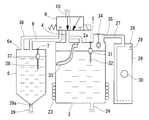
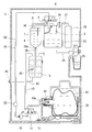
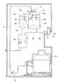
- Sectional drawing which shows the water server of embodiment of this invention 1 is an enlarged sectional view of the vicinity of the cold water tank and buffer tank of the water server in FIG. Sectional drawing of the container holder vicinity which shows the state which pulled out the container holder shown in FIG. 1 from a housing
- Sectional drawing which shows the state in which the 1st water level sensor in the cold water tank shown in FIG. 4 caused malfunction, and the water level in the cold water tank continued rising.
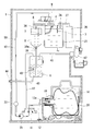
- Sectional drawing which shows the state which the 2nd water level sensor in the buffer tank shown in FIG. 5 caused malfunction, and the water level in a buffer tank continued rising.
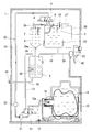
- Sectional drawing which shows the state which the upper three-way valve shown in FIG. 6 caused malfunction, and the water level in a cold water tank continued rising
- FIG. 6 is a cross-sectional view showing a state in which the lower three-way valve shown in FIG. 6 has malfunctioned and the water level in the buffer tank continues to rise.
- Sectional drawing which shows the water server of the reference example which the inventor of this application examined
- the water server includes a housing 1, a cold water tank 2 that stores low-temperature drinking water to be poured out of the housing 1, a first water level sensor 3 that detects a water level in the cold water tank 2, A cold water tank water supply pipe 4 for introducing drinking water into the cold water tank 2 when the water level detected by the 1 water level sensor 3 drops, and a hot water tank for storing hot drinking water for pouring out of the housing 1 5, a buffer tank 6 disposed above the hot water tank 5, a second water level sensor 7 for detecting the water level in the buffer tank 6, and a buffer tank when the water level detected by the second water level sensor 7 decreases 6, a buffer tank water supply pipe 8 for introducing drinking water, a cold water tank water supply pipe 4, a pump installation pipe 10 connected to the upstream side of the buffer tank water supply pipe 8 via an upper three-way valve 9, and a pump installation pipe 10 Downstream upstream Having a raw water container connecting pipe 12 and the circulation pipe 13 connected via a-
- the raw water container 14 is provided with a hollow cylindrical body portion 15, a bottom portion 16 provided at one end of the body portion 15, and a shoulder portion 17 at the other end of the body portion 15.
- the neck 18 is provided with a water outlet 19.
- the trunk portion 15 of the raw water container 14 is formed with flexibility so as to contract as the residual water amount decreases.
- the raw water container 14 is formed by blow molding of polyethylene terephthalate resin (PET).
- PET polyethylene terephthalate resin
- the capacity of the raw water container 14 is about 10 to 20 liters when it is full.
- a container (a so-called bag-in-box) in which a connector having a water outlet 19 is bonded to a resin film bag by heat welding or the like is accommodated in a box such as a cardboard box may be adopted.
- the raw water container 14 is supported by a container holder 20.
- the container holder 20 is placed horizontally between a housing position (the position shown in FIG. 1) where the raw water container 14 is housed in the housing 1 and a drawing position (the position shown in FIG. 3) where the raw water container 14 comes out from the housing 1. It is supported movably.
- the raw water container 14 is supported by the container holder 20 so that the water outlet 19 faces horizontally.
- the end 12a of the raw water container connection pipe 12 on the raw water container 14 side is separated from the water outlet 19 of the raw water container 14 when the container holder 20 is moved to the drawing position, and is shown in FIG.
- the container holder 20 is moved to the accommodation position, it is fixed in the housing 1 so as to be connected to the water outlet 19 of the raw water container 14.
- the pump installation pipe 10 is provided with a pump 21 for transferring drinking water in the pump installation pipe 10 from the lower three-way valve 11 side to the upper three-way valve 9 side.
- a diaphragm pump can be used.
- the diaphragm pump has only a diaphragm (not shown) that reciprocates, a pump chamber whose volume is increased or decreased by the reciprocation of the diaphragm, an intake port and a discharge port provided in the pump chamber, and a flow in a direction flowing into the pump chamber. It has a suction side check valve provided at the suction port so as to allow, and a discharge side check valve provided at the discharge port so as to allow only the flow in the direction of flowing out from the pump chamber.
- the volume of the pump chamber increases, drinking water is sucked from the suction port, and when the volume of the pump chamber decreases due to the backward movement of the diaphragm, the drinking water is discharged from the discharge port.
- the gear pump includes a casing (not shown), a pair of meshing gears housed in the casing, and a suction chamber and a discharge chamber in the casing defined by meshing portions of the pair of gears.
- the drinking water confined between the tooth gap and the inner surface of the casing is transferred from the suction chamber side to the discharge chamber side by rotation of the gear.
- a flow rate sensor 22 is provided on the discharge side of the pump 21 of the pump installation pipe 10.
- the flow sensor 22 detects the state when the flow of drinking water in the pump installation pipe 10 is lost during the operation of the pump 21.
- a container replacement lamp (not shown) arranged in front of the housing 1 is turned on to inform the user that it is time to replace the raw water container 14.
- the upper three-way valve 9 communicates between the pump installation pipe 10 and the chilled water tank water supply pipe 4 and cuts off the connection between the pump installation pipe 10 and the buffer tank water supply pipe 8 (see FIG. 1).
- the flow path can be switched between the buffer side connection position (see FIG. 6) that blocks between the pipe 10 and the cold water tank water supply pipe 4 and communicates between the pump installation pipe 10 and the buffer tank water supply pipe 8.
- the upper three-way valve 9 employs an electromagnetic valve that switches from the cold water side connection position to the buffer side connection position when energized, and switches from the buffer side connection position to the cold water side connection position when power is released.
- the lower three-way valve 11 communicates between the pump installation pipe 10 and the raw water container connection pipe 12 and blocks between the pump installation pipe 10 and the circulation pipe 13 (see FIG. 1), and the pump installation pipe 10 and the raw water container connection pipe 12 are configured to be able to switch between a circulation side connection position (see FIG. 6) between the pump installation pipe 10 and the circulation pipe 13 that is cut off between the pipe 10 and the raw water container connection pipe 12. .
- the lower three-way valve 11 switches from the raw water side connection position to the circulation side connection position by energizing, and switches from the circulation side connection position to the raw water side connection position by releasing the current.
- a solenoid valve is used.
- the circulation pipe 13 connects between the lower three-way valve 11 and the hot water tank 5.
- the cold water tank 2 contains air and drinking water in two upper and lower layers.
- a cooling device 23 is attached to the cold water tank 2 to keep the drinking water stored in the cold water tank 2 at a predetermined low temperature (about 5 ° C.).
- a cold water pouring pipe 24 Connected to the bottom of the cold water tank 2 is a cold water pouring pipe 24 for pouring low temperature drinking water in the cold water tank 2 to the outside.
- the cold water pouring pipe 24 is provided with a cold water cock 25 that can be operated from the outside of the housing 1. By opening the cold water cock 25, low-temperature drinking water can be poured from the cold water tank 2 into a cup or the like. ing.
- the capacity of drinking water in the cold water tank 2 is smaller than the capacity of the raw water container 14 and is about 1 to 3 liters.
- the air sterilization chamber 26 includes a hollow case 29 in which an atmosphere opening 28 is formed, and an ozone generator 30 provided in the case 29.
- the ozone generator 30 include a low-pressure mercury lamp that irradiates oxygen in the air with ultraviolet rays to change the oxygen into ozone, or an AC voltage applied between a pair of opposed electrodes covered with an insulator. A silent discharge device that changes oxygen into ozone can be used.
- the air sterilization chamber 26 is always in a state where ozone is accumulated in the case 29 by energizing the ozone generator 30 at regular intervals to generate ozone.
- the atmosphere communication passage 27 keeps the inside of the cold water tank 2 at atmospheric pressure by communicating the air layer in the cold water tank 2 to the atmosphere. That is, when the water level in the cold water tank 2 drops, the atmospheric communication passage 27 introduces air from the atmosphere into the cold water tank 2 via the air sterilization chamber 26 according to the drop, and the atmospheric pressure in the cold water tank 2 is reduced. Keep on. At this time, since the air introduced into the cold water tank 2 passes through the air sterilization chamber 26 and is sterilized with ozone, the air in the cold water tank 2 is kept clean.
- an air communication path 27 having an air sterilization chamber 26 for sterilizing the air with ozone is employed to improve the hygiene in the cold water tank 2, but the upper surface 2 a of the cold water tank 2 is used as the air communication path 27. It is also possible to adopt a simple one in which an opening for communication with the atmosphere is formed and an air filter is attached to the opening.
- a first water level sensor 3 is attached to the upper surface 2 a of the cold water tank 2.
- the first water level sensor 3 may be of a type that can detect water levels in a plurality of stages, but in this embodiment, the water level in the cold water tank 2 is less than a preset set water level or a set water level.
- a binary system that detects whether or not the above is used.
- Such a first water level sensor 3 has a float 31 having a specific gravity smaller than that of drinking water, and a stem 32 that holds the float 31 so as to be movable up and down. Includes a built-in reed switch.
- the first water level sensor 3 detects whether the reed switch is turned on by relative movement of the magnet in the float 31 and the reed switch in the stem 32 when the float 31 moves up and down in conjunction with the upper and lower levels of the water level in the cold water tank 2. OFF switches.
- the end of the cold water tank water supply pipe 4 on the cold water tank 2 side is connected to the upper surface 2 a of the cold water tank 2.
- a guide plate 33 that changes the flow of vertical drinking water flowing into the cold water tank 2 into a horizontal flow when the drinking water is introduced from the cold water tank water supply pipe 4 into the cold water tank 2. Is provided.
- the guide plate 33 prevents low-temperature drinking water accumulated in the lower part of the cold water tank 2 from being stirred by normal temperature drinking water flowing into the cold water tank 2 from the cold water tank water supply pipe 4.
- an abnormal water level sensor 34 is attached to the cold water tank 2.
- the abnormal water level sensor 34 is for detecting when the water level in the cold water tank 2 reaches the abnormal water level.
- a binary sensor that detects whether the water level in the cold water tank 2 is lower than the abnormal water level or higher than the abnormal water level can be used.
- the abnormal water level is a water level set in advance at a position higher than the set water level of the first water level sensor 3 (for example, a position 10 to 20 mm higher than the set water level of the first water level sensor 3).
- the abnormal water level sensor 34 when the abnormal water level sensor 34 is attached to a sensor housing recess 35 formed on the upper surface 2a of the cold water tank 2, the space occupied by the cold water tank 2 in the housing 1 is suppressed, and the housing 1 is reduced in size. Can be realized.
- the end of the air communication passage 27 on the cold water tank 2 side is located inside the sensor housing recess 35 in order to reliably prevent drinking water from entering the air communication passage 27 when the water level in the cold water tank 2 rises to an abnormal water level. Is open.
- the buffer tank 6 contains air and drinking water in upper and lower layers.
- the buffer tank 6 is provided separately from the cold water tank 2 so as to have a water level independent of the water level in the cold water tank 2. That is, the drinking water layer in the buffer tank 6 and the drinking water layer in the cold water tank 2 are not in communication, and the water level in the buffer tank 6 and the water level in the cold water tank 2 can be changed separately. ing.
- the buffer tank 6 is connected to a vent pipe 36 that allows the outflow and inflow of air.
- One end of the vent pipe 36 is connected to the upper surface 6 a of the buffer tank 6, and the other end is connected to the upper surface 2 a of the cold water tank 2, and the air pipe 36 is connected between the air layer in the buffer tank 6 and the air layer in the cold water tank 2.
- the vent pipe 36 is configured to permit air flow only between the buffer tank 6 and the cold water tank 2 and to have no air flow path other than that.
- the air layer in the buffer tank 6 is in communication with the air communication path 27 through the inside of the vent pipe 36 and the air layer in the cold water tank 2 in this order.
- a second water level sensor 7 is attached to the upper surface 6 a of the buffer tank 6.
- the second water level sensor 7 is a binary type sensor that detects whether the water level in the buffer tank 6 is lower than a preset water level or higher than a preset water level.
- the second water level sensor 7 has a float 37 having a specific gravity smaller than that of drinking water and a stem 38 that holds the float 37 so as to be movable up and down.
- the end of the buffer tank water supply pipe 8 on the buffer tank 6 side is connected to the upper surface 6 a of the buffer tank 6.
- the capacity of drinking water in the buffer tank 6 is smaller than that of the hot water tank 5 and is about 0.2 to 0.5 liter. As will be described later, the drinking water in the buffer tank 6 has a role to push out the drinking water in the hot water tank 5 when the hot drinking water in the hot water tank 5 is poured out. Therefore, it is preferable that the buffer tank 6 has a vertically elongated shape (for example, a cylindrical shape whose height is larger than the diameter). In this way, even if the capacity of the drinking water in the buffer tank 6 is small, a relatively high water pressure is generated in the lower part of the buffer tank 6, so that the force for pushing the drinking water in the hot water tank 5 to the outside is effectively obtained. It becomes possible.
- the bottom of the buffer tank 6 is connected to the end of the hot water tank water supply pipe 39 connecting the buffer tank 6 and the hot water tank 5 on the buffer tank 6 side.
- a check valve 39a is provided at the end of the warm water tank water supply pipe 39 on the buffer tank 6 side.
- the check valve 39a allows the flow of drinking water from the buffer tank 6 side to the hot water tank 5 side, but prevents the flow of drinking water from the hot water tank 5 side to the buffer tank 6 side.
- the hot water tank 5 is completely filled with drinking water.
- the warm water tank 5 is equipped with a heater 40 that keeps the drinking water stored in the warm water tank 5 at a predetermined high temperature (about 90 ° C.).
- a hot water pouring pipe 41 for pouring hot drinking water accumulated in the upper part of the hot water tank 5 to the outside.
- the hot water pouring pipe 41 is provided with a hot water cock 42 that can be operated from the outside of the housing 1. By opening the hot water cock 42, hot drinking water can be poured from the hot water tank 5 into a cup or the like. ing.
- the drinking water in the buffer tank 6 is introduced into the hot water tank 5 by its own weight through the hot water tank water supply pipe 39, and the hot water tank 5 is always kept in a full water state.
- the capacity of the drinking water in the hot water tank 5 is about 1 to 2 liters.
- a drain pipe 43 extending to the outside of the housing 1 is connected to the bottom surface of the hot water tank 5.
- the outlet of the drain pipe 43 is closed with a plug 44.
- An opening / closing valve may be provided instead of the plug 44.
- the cold water cock 25 when the cold water cock 25 is operated, the low-temperature drinking water in the cold water tank 2 is poured out through the cold water pouring pipe 24 by its own weight. At this time, the water level in the cold water tank 2 falls.
- the first water level sensor 3 detects that the water level in the cold water tank 2 is lower than the set water level
- the upper three-way valve 9 is switched to the cold water side connection position and the lower three-way valve 11 is switched to the raw water side connection position.
- the pump 21 operates. Thereby, the drinking water filled in the raw water container 14 passes through the raw water container connection pipe 12, the lower three-way valve 11, the pump installation pipe 10, the upper three-way valve 9, and the cold water tank water supply pipe 4 in this order to the cold water tank 2.
- the pump 21 stops.
- the pump 21 by operating the pump 21 according to the water level detected by the first water level sensor 3, the water level in the cold water tank 2 can be maintained within a certain range.
- the pump 21 When the first water level sensor 3 detects that the water level in the cold water tank 2 is equal to or higher than the set water level, the pump 21 is not stopped immediately, but after the pump 21 is continuously driven for a predetermined time.
- the pump 21 is preferably stopped. Thereby, the chattering phenomenon (a phenomenon in which the start and stop of the pump 21 are repeated finely in a short time) due to the ripple of the water surface in the cold water tank 2 can be prevented.
- the type which can detect the water level of several steps as the 1st water level sensor 3 when the 1st water level sensor 3 detects that the water level in the cold water tank 2 has reached the predetermined upper limit water level
- the pump 21 may be stopped.
- the pump 21 When the second water level sensor 7 detects that the water level in the buffer tank 6 has become less than the set water level, the upper three-way valve 9 is switched to the buffer side connection position and the lower three-way valve 11 is switched to the raw water side connection position. In this state, the pump 21 operates. Thereby, the drinking water filled in the raw water container 14 passes through the raw water container connection pipe 12, the lower three-way valve 11, the pump installation pipe 10, the upper three-way valve 9, and the buffer tank water supply pipe 8 in this order to the buffer tank 6. Inflow. Thereafter, when the second water level sensor 7 detects that the water level in the buffer tank 6 has become equal to or higher than the set water level, the pump 21 stops. Thus, by operating the pump 21 according to the water level detected by the second water level sensor 7, the water level in the buffer tank 6 can be maintained within a certain range.
- the pump 21 when the second water level sensor 7 detects that the water level in the buffer tank 6 is equal to or higher than the set water level, the pump 21 is not stopped immediately but is continuously driven for a predetermined time after that. Then, it is preferable to stop the pump 21. Thereby, the chattering phenomenon by the ripple of the water surface in the buffer tank 6 can be prevented.
- the second water level sensor 7 is of a type that can detect water levels in a plurality of stages, the second water level sensor 7 detects that the water level in the buffer tank 6 has reached a predetermined upper limit water level. In addition, the pump 21 may be stopped.
- This water server can be sterilized to maintain internal hygiene.
- the sterilization operation is an operation for sterilizing the circulation path 50 at a high temperature by circulating hot drinking water in the hot water tank 5 through the circulation path 50 including the buffer tank 6 and the pump installation pipe 10. This sterilization operation is started when the user operates a button (not shown) arranged on the front surface of the housing 1. The sterilization operation after the next time is automatically performed every day when the elapsed time from the time when the first sterilization operation is performed is counted by a timer built in the water server.
- the heater 40 of the hot water tank 5 heats the drinking water passing through the hot water tank 5, so that the circulation path 50 (here, the hot water tank 5, the circulation pipe 13, the lower three-way valve 11, the pump installation pipe 10, The temperature of the drinking water circulating through the upper three-way valve 9, the buffer tank water supply pipe 8, the buffer tank 6, and the hot water tank water supply pipe 39) is raised to the sterilization temperature (for example, 80 ° C.) as a whole.
- the sterilization temperature for example, 80 ° C.
- hot drinking water does not pass through the cold water tank 2. Therefore, it is possible to ensure the safety and convenience of the user. That is, if hot drinking water passes through the cold water tank 2 during the sterilization operation, when the cold water cock 25 is operated during the sterilization operation, the hot drinking water is poured out from the cold water cock 25, and the user is burned. There is danger. On the other hand, in this water server, since the circulation path 50 during the sterilization operation does not pass through the cold water tank 2, the user can pour out the low-temperature drinking water in the cold water tank 2 even during the sterilization operation. There is no fear.
- the first water level sensor 3, the second water level sensor 7, the upper three-way valve 9, the lower three-way valve 11 and the like may cause malfunction.
- the float 31 of the first water level sensor 3 or the second water level sensor 7 is caused by the precipitation of mineral components contained in the drinking water. It is assumed that the float 37 is difficult to move or that the upper three-way valve 9 or the lower three-way valve 11 is difficult to switch.
- the abnormality if the abnormality cannot be detected, a situation in which the water level in the cold water tank 2 or the buffer tank 6 continues to rise may occur, and water may leak from the water server. There is.
- the abnormal water level sensor 34 detects the abnormality, and the pump 21 And a lamp (not shown) arranged on the front surface of the housing 1 is lit to notify the user of the abnormality. This will be described below.
- a malfunction occurs in the first water level sensor 3 and the float 31 of the first water level sensor 3 does not rise even though the pump 21 is operating in response to a decrease in the water level in the cold water tank 2.
- the pump 21 does not stop even if the water level in the cold water tank 2 exceeds the set water level, and the water level in the cold water tank 2 rises.
- the abnormal water level sensor 34 detects this.
- the pump 21 is stopped and the lamp is turned on to notify the user of the abnormality. In this way, it is possible to prevent water leakage due to malfunction of the first water level sensor 3.
- the malfunction of the second water level sensor 7 occurs, and the float 21 of the second water level sensor 7 rises even though the pump 21 is operating in response to a decrease in the water level in the buffer tank 6. Assume the case of not. At this time, since the second water level sensor 7 does not detect a rise in the water level in the buffer tank 6, the pump 21 does not stop even if the water level in the buffer tank 6 exceeds the set water level, and the water level in the buffer tank 6 rises. Continue. Thereafter, when the water level in the buffer tank 6 reaches the upper surface 6a of the buffer tank 6, the drinking water overflowing from the buffer tank 6 flows into the cold water tank 2 through the vent pipe 36, and the water level in the cold water tank 2 starts to rise. .
- the abnormal water level sensor 34 detects this. At this time, the pump 21 is stopped and the lamp is turned on to notify the user of the abnormality. In this way, it is possible to prevent water leakage due to malfunction of the second water level sensor 7.
- the upper three-way valve 9 malfunctions and the upper three-way valve 9 is not switched from the cold water side connection position to the buffer side connection position when the sterilization operation is started.
- the drinking water flowing out from the buffer tank 6 should return to the buffer tank 6, but the drinking water flowing out from the buffer tank 6 flows into the cold water tank 2 without returning to the buffer tank 6.
- the water level in 6 continues to fall and the water level in the cold water tank 2 continues to rise.
- the abnormal water level sensor 34 detects this.
- the pump 21 is stopped and the lamp is turned on to notify the user of the abnormality. In this way, it is possible to prevent water leakage due to malfunction of the upper three-way valve 9.
- the abnormal water level sensor 34 detects this. At this time, the pump 21 is stopped and the lamp is turned on to notify the user of the abnormality. In this way, it is possible to prevent water leakage due to malfunction of the lower three-way valve 11.
- this water server can detect the abnormality with the abnormal water level sensor 34 when the water level in the cold water tank 2 continues to rise due to some abnormality. Further, since the cold water tank 2 and the buffer tank 6 communicate with each other via the vent pipe 36, when the water level in the buffer tank 6 continues to rise due to some abnormality, the drinking water overflowing from the buffer tank 6 is vented. It flows into the cold water tank 2 through 36, and the water level of the cold water tank 2 rises. Therefore, even when the water level in the buffer tank 6 continues to rise due to some abnormality, the abnormality can be detected by the abnormal water level sensor 34.
- the abnormality is detected by the abnormal water level sensor 34 of the cold water tank 2. It is possible to monitor both the cold water tank 2 and the buffer tank 6 with a single abnormal water level sensor 34. Therefore, it is not necessary to provide an abnormal water level sensor in the buffer tank 6, and the cost is low. Further, since the air layer of the cold water tank 2 and the air layer of the buffer tank 6 communicate with each other via the vent pipe 36, it is not necessary to provide an atmosphere communication path in the buffer tank 6. Therefore, it is possible to reduce the possibility that various germs enter from the atmosphere, and it is hygienic.
- the water server employing the cold water tank 2 and the buffer tank 6 is described as an example of the tank in which the first water level sensor 3 and the second water level sensor 7 are provided. It may be adopted for a water server.
- a cold water tank and a hot water tank may be configured to store air and drinking water in two layers, and a first water level sensor and a second water level sensor may be provided in the cold water tank and the hot water tank, respectively.
- the air communication path can be provided in the cold water tank
- the vent pipe can be provided so as to communicate between the air layer of the cold water tank and the air layer of the hot water tank
- the abnormal water level sensor can be provided in the cold water tank.
Landscapes
- Physics & Mathematics (AREA)
- Fluid Mechanics (AREA)
- General Physics & Mathematics (AREA)
- Devices For Dispensing Beverages (AREA)
Abstract
Description
空気と飲料水を上下二層に収容する第1タンクと、
その第1タンク内の水位を検知する第1水位センサと、
その第1水位センサで検知される水位が低下したときに前記第1タンクに飲料水を導入する第1給水管と、
空気と飲料水を上下二層に収容し、前記第1タンク内の水位とは独立した水位をもつように第1タンクとは別個に設けられた第2タンクと、
その第2タンク内の水位を検知する第2水位センサと、
その第2水位センサで検知される水位が低下したときに前記第2タンクに飲料水を導入する第2給水管と、
前記第1タンクを大気圧に保つように第1タンクに設けられた大気連通路と、
前記第1タンクの空気層と前記第2タンクの空気層の間を連通する通気管と、
前記第1タンク内の水位が異常水位に達したことを検知する異常水位センサと、
を有する。
前記第1給水管および前記第2給水管の上流側に上部三方弁を介して接続されたポンプ設置管と、そのポンプ設置管の上流側に下部三方弁を介して接続された原水容器接続管および循環用配管と、前記原水容器接続管に接続された交換式の原水容器と、前記循環用配管に接続された前記温水タンクとを更に有し、
前記上部三方弁は、前記ポンプ設置管と前記第1給水管の間を連通しかつ前記ポンプ設置管と前記第2給水管の間を遮断する第1接続位置と、前記ポンプ設置管と前記第1給水管の間を遮断しかつ前記ポンプ設置管と前記第2給水管の間を連通する第2接続位置との間で流路を切り替え可能に構成され、
前記下部三方弁は、前記ポンプ設置管と前記原水容器接続管の間を連通しかつ前記ポンプ設置管と前記循環用配管の間を遮断する原水側接続位置と、前記ポンプ設置管と前記原水容器接続管の間を遮断しかつ前記ポンプ設置管と前記循環用配管の間を連通する循環側接続位置との間で流路を切り換え可能に構成されている。
3 第1水位センサ
4 冷水タンク給水管
5 温水タンク
6 バッファタンク
7 第2水位センサ
8 バッファタンク給水管
9 上部三方弁
10 ポンプ設置管
11 下部三方弁
12 原水容器接続管
13 循環用配管
14 原水容器
27 大気連通路
34 異常水位センサ
36 通気管
Claims (3)
- 空気と飲料水を上下二層に収容する第1タンク(2)と、
その第1タンク(2)内の水位を検知する第1水位センサ(3)と、
その第1水位センサ(3)で検知される水位が低下したときに前記第1タンク(2)に飲料水を導入する第1給水管(4)と、
空気と飲料水を上下二層に収容し、前記第1タンク(2)内の水位とは独立した水位をもつように第1タンク(2)とは別個に設けられた第2タンク(6)と、
その第2タンク(6)内の水位を検知する第2水位センサ(7)と、
その第2水位センサ(7)で検知される水位が低下したときに前記第2タンク(6)に飲料水を導入する第2給水管(8)と、
前記第1タンク(2)を大気圧に保つように第1タンク(2)に設けられた大気連通路(27)と、
前記第1タンク(2)の空気層と前記第2タンク(6)の空気層の間を連通する通気管(36)と、
前記第1タンク(2)内の水位が異常水位に達したことを検知する異常水位センサ(34)と、
を有するウォーターサーバー。 - 前記第1タンク(2)は、外部に注出するための低温の飲料水を収容する冷水タンクであり、
前記第2タンク(6)は、外部に注出するための高温の飲料水を収容する温水タンク(5)の上方に配置され、温水タンク(5)内の高温の飲料水を外部に注出するときに温水タンク(5)内の飲料水を外部に押し出すための飲料水を収容するバッファタンクである請求項1に記載のウォーターサーバー。 - 前記第1給水管(4)および前記第2給水管(8)の上流側に上部三方弁(9)を介して接続されたポンプ設置管(10)と、そのポンプ設置管(10)の上流側に下部三方弁(11)を介して接続された原水容器接続管(12)および循環用配管(13)と、前記原水容器接続管(12)に接続された交換式の原水容器(14)と、前記循環用配管(13)に接続された前記温水タンク(5)とを更に有し、
前記上部三方弁(9)は、前記ポンプ設置管(10)と前記第1給水管(4)の間を連通しかつ前記ポンプ設置管(10)と前記第2給水管(8)の間を遮断する第1接続位置と、前記ポンプ設置管(10)と前記第1給水管(4)の間を遮断しかつ前記ポンプ設置管(10)と前記第2給水管(8)の間を連通する第2接続位置との間で流路を切り替え可能に構成され、
前記下部三方弁(11)は、前記ポンプ設置管(10)と前記原水容器接続管(12)の間を連通しかつ前記ポンプ設置管(10)と前記循環用配管(13)の間を遮断する原水側接続位置と、前記ポンプ設置管(10)と前記原水容器接続管(12)の間を遮断しかつ前記ポンプ設置管(10)と前記循環用配管(13)の間を連通する循環側接続位置との間で流路を切り換え可能に構成されている、
請求項2に記載のウォーターサーバー。
Priority Applications (4)
| Application Number | Priority Date | Filing Date | Title |
|---|---|---|---|
| EP13880633.6A EP2980012A4 (en) | 2013-03-26 | 2013-12-19 | WASSERSERVIERER |
| KR1020157030485A KR102092436B1 (ko) | 2013-03-26 | 2013-12-19 | 워터 서버 |
| CN201380075062.2A CN105050937B (zh) | 2013-03-26 | 2013-12-19 | 饮水机 |
| US14/780,032 US20160046478A1 (en) | 2013-03-26 | 2013-12-19 | Water dispenser |
Applications Claiming Priority (2)
| Application Number | Priority Date | Filing Date | Title |
|---|---|---|---|
| JP2013063771A JP5571218B1 (ja) | 2013-03-26 | 2013-03-26 | ウォーターサーバー |
| JP2013-063771 | 2013-03-26 |
Publications (1)
| Publication Number | Publication Date |
|---|---|
| WO2014155871A1 true WO2014155871A1 (ja) | 2014-10-02 |
Family
ID=51427267
Family Applications (1)
| Application Number | Title | Priority Date | Filing Date |
|---|---|---|---|
| PCT/JP2013/084073 Ceased WO2014155871A1 (ja) | 2013-03-26 | 2013-12-19 | ウォーターサーバー |
Country Status (7)
| Country | Link |
|---|---|
| US (1) | US20160046478A1 (ja) |
| EP (1) | EP2980012A4 (ja) |
| JP (1) | JP5571218B1 (ja) |
| KR (1) | KR102092436B1 (ja) |
| CN (1) | CN105050937B (ja) |
| TW (1) | TWI624632B (ja) |
| WO (1) | WO2014155871A1 (ja) |
Families Citing this family (9)
| Publication number | Priority date | Publication date | Assignee | Title |
|---|---|---|---|---|
| JP6276938B2 (ja) * | 2013-08-02 | 2018-02-07 | ネビオット−ネイチャー オブ ガリラヤ リミテッドNeviot−Nature Of Galilee Ltd. | 箱に入った袋のユニットを有するウォーターディスペンサ |
| WO2018064451A1 (en) * | 2016-09-30 | 2018-04-05 | The Coca-Cola Company | Beverage dispensing systems |
| JP6814052B2 (ja) * | 2017-01-18 | 2021-01-13 | 株式会社コスモライフ | ウォーターサーバー |
| JP6894626B2 (ja) * | 2017-07-14 | 2021-06-30 | パーパス株式会社 | 補水制御方法およびウォーターサーバー |
| KR102669901B1 (ko) * | 2018-04-02 | 2024-05-29 | 코웨이 주식회사 | 냉수탱크를 구비한 정수기 및 이의 제어 방법 |
| WO2019246476A1 (en) * | 2018-06-22 | 2019-12-26 | Bissell Inc. | Apparatus for cleaning a surface |
| CN111685597A (zh) * | 2019-03-13 | 2020-09-22 | 佛山市顺德区美的饮水机制造有限公司 | 饮水机和饮水机的控制方法 |
| KR102370327B1 (ko) * | 2020-01-29 | 2022-03-04 | 정하익 | 정수기 |
| PL4112535T4 (pl) * | 2021-06-28 | 2024-07-29 | Scandinavian Innovation Group Oy | Dozownik zimnej i ciepłej wody pitnej z obwodem do dezynfekcji |
Citations (7)
| Publication number | Priority date | Publication date | Assignee | Title |
|---|---|---|---|---|
| JPS50150400U (ja) * | 1974-05-29 | 1975-12-13 | ||
| JPH0485091U (ja) * | 1990-11-30 | 1992-07-23 | ||
| JP2004101049A (ja) * | 2002-09-09 | 2004-04-02 | Fuji Electric Retail Systems Co Ltd | 温水供給装置およびこれを用いた飲料供給装置 |
| WO2004102089A1 (ja) * | 2003-05-14 | 2004-11-25 | Kyusyu Kaihatsu Kikaku Co., Ltd. | 飲料用給水機及び飲料用給水機に用いられる水タンク収容容器 |
| JP2006115866A (ja) * | 2004-10-19 | 2006-05-11 | Kyushu Kaihatsu Kikaku:Kk | 飲料用給水機 |
| JP2011106759A (ja) * | 2009-11-18 | 2011-06-02 | Kyushu Kaihatsu Kikaku:Kk | 給水機 |
| JP2012162318A (ja) | 2011-02-09 | 2012-08-30 | Air Water Inc | 飲料水サーバ |
Family Cites Families (16)
| Publication number | Priority date | Publication date | Assignee | Title |
|---|---|---|---|---|
| US3960295A (en) * | 1974-08-19 | 1976-06-01 | Vladimir Horak | Continuous liquid proportioning system |
| US4284210A (en) * | 1977-12-21 | 1981-08-18 | Vladimir Horak | Static metering pump |
| US4792059A (en) * | 1987-02-04 | 1988-12-20 | United States Thermoelectric Corporation | Sealed hot, cold and room temperature pure water dispenser |
| US4958747A (en) * | 1988-08-15 | 1990-09-25 | Sheets Kerney T | Bottled water dispenser |
| GB2236736A (en) * | 1989-09-27 | 1991-04-17 | Isoworth Ltd | Carbonation apparatus for dispensing drinks, with plural carbonation chambers |
| JPH0485091A (ja) * | 1990-07-27 | 1992-03-18 | Kobayashi Kirokushi Kk | ラベル付き帳票の製造方法、およびそのラベル付き帳票 |
| JP3601012B2 (ja) * | 1994-09-08 | 2004-12-15 | ホシザキ電機株式会社 | 貯湯タンクの給水装置 |
| JP2001029981A (ja) * | 1999-07-26 | 2001-02-06 | Cosmo Life Kk | 有機性排水処理方法及び装置 |
| TW501713U (en) * | 2001-08-28 | 2002-09-01 | Ming-De Jang | Water supply device for drinking water dispenser |
| US6868986B1 (en) * | 2003-02-10 | 2005-03-22 | Christopher Paul Arnold | Bottled water pump |
| JP4549037B2 (ja) * | 2003-06-16 | 2010-09-22 | サントリーフーズ株式会社 | 飲料供給装置及び飲料供給方法 |
| DE602005008329D1 (de) * | 2004-10-06 | 2008-09-04 | Cosmo Life Kk | Kartusche für Getränkespender und Stützvorrichtung dafür |
| US8281821B2 (en) * | 2006-08-30 | 2012-10-09 | MTN Products, Inc | Leak stop seal for water cooler |
| CN101221062A (zh) * | 2007-01-10 | 2008-07-16 | 陞达科技股份有限公司 | 液位检测模组及液体供应系统 |
| US20120189502A1 (en) * | 2008-07-11 | 2012-07-26 | George Yui | Bottom-loading water coolers with ozone sterilizing devices |
| CN201530719U (zh) * | 2009-09-21 | 2010-07-21 | 邬志坚 | 一种啤酒机 |
-
2013
- 2013-03-26 JP JP2013063771A patent/JP5571218B1/ja active Active
- 2013-12-19 US US14/780,032 patent/US20160046478A1/en not_active Abandoned
- 2013-12-19 CN CN201380075062.2A patent/CN105050937B/zh active Active
- 2013-12-19 WO PCT/JP2013/084073 patent/WO2014155871A1/ja not_active Ceased
- 2013-12-19 KR KR1020157030485A patent/KR102092436B1/ko active Active
- 2013-12-19 EP EP13880633.6A patent/EP2980012A4/en not_active Withdrawn
-
2014
- 2014-03-07 TW TW103108036A patent/TWI624632B/zh active
Patent Citations (7)
| Publication number | Priority date | Publication date | Assignee | Title |
|---|---|---|---|---|
| JPS50150400U (ja) * | 1974-05-29 | 1975-12-13 | ||
| JPH0485091U (ja) * | 1990-11-30 | 1992-07-23 | ||
| JP2004101049A (ja) * | 2002-09-09 | 2004-04-02 | Fuji Electric Retail Systems Co Ltd | 温水供給装置およびこれを用いた飲料供給装置 |
| WO2004102089A1 (ja) * | 2003-05-14 | 2004-11-25 | Kyusyu Kaihatsu Kikaku Co., Ltd. | 飲料用給水機及び飲料用給水機に用いられる水タンク収容容器 |
| JP2006115866A (ja) * | 2004-10-19 | 2006-05-11 | Kyushu Kaihatsu Kikaku:Kk | 飲料用給水機 |
| JP2011106759A (ja) * | 2009-11-18 | 2011-06-02 | Kyushu Kaihatsu Kikaku:Kk | 給水機 |
| JP2012162318A (ja) | 2011-02-09 | 2012-08-30 | Air Water Inc | 飲料水サーバ |
Non-Patent Citations (1)
| Title |
|---|
| See also references of EP2980012A4 |
Also Published As
| Publication number | Publication date |
|---|---|
| EP2980012A4 (en) | 2016-09-21 |
| JP5571218B1 (ja) | 2014-08-13 |
| TW201447193A (zh) | 2014-12-16 |
| CN105050937B (zh) | 2017-03-08 |
| US20160046478A1 (en) | 2016-02-18 |
| EP2980012A1 (en) | 2016-02-03 |
| KR102092436B1 (ko) | 2020-03-23 |
| KR20150133823A (ko) | 2015-11-30 |
| TWI624632B (zh) | 2018-05-21 |
| CN105050937A (zh) | 2015-11-11 |
| JP2014189281A (ja) | 2014-10-06 |
Similar Documents
| Publication | Publication Date | Title |
|---|---|---|
| JP5571218B1 (ja) | ウォーターサーバー | |
| JP5529314B1 (ja) | ウォーターサーバー | |
| KR102089823B1 (ko) | 워터 서버 | |
| KR102092434B1 (ko) | 워터 서버 | |
| JP5529201B2 (ja) | ウォーターサーバー | |
| JP6084484B2 (ja) | ウォーターサーバー | |
| CN104203804A (zh) | 饮水机 | |
| KR20150058142A (ko) | 워터 서버 | |
| JP5647636B2 (ja) | ウォーターサーバー | |
| JP5520404B1 (ja) | ウォーターサーバー |
Legal Events
| Date | Code | Title | Description |
|---|---|---|---|
| WWE | Wipo information: entry into national phase |
Ref document number: 201380075062.2 Country of ref document: CN |
|
| 121 | Ep: the epo has been informed by wipo that ep was designated in this application |
Ref document number: 13880633 Country of ref document: EP Kind code of ref document: A1 |
|
| WWE | Wipo information: entry into national phase |
Ref document number: 14780032 Country of ref document: US |
|
| NENP | Non-entry into the national phase |
Ref country code: DE |
|
| ENP | Entry into the national phase |
Ref document number: 20157030485 Country of ref document: KR Kind code of ref document: A |
|
| REEP | Request for entry into the european phase |
Ref document number: 2013880633 Country of ref document: EP |
|
| WWE | Wipo information: entry into national phase |
Ref document number: 2013880633 Country of ref document: EP |