WO2014155928A1 - 燃料電池 - Google Patents
燃料電池 Download PDFInfo
- Publication number
- WO2014155928A1 WO2014155928A1 PCT/JP2014/000607 JP2014000607W WO2014155928A1 WO 2014155928 A1 WO2014155928 A1 WO 2014155928A1 JP 2014000607 W JP2014000607 W JP 2014000607W WO 2014155928 A1 WO2014155928 A1 WO 2014155928A1
- Authority
- WO
- WIPO (PCT)
- Prior art keywords
- cell stack
- fuel cell
- cell
- gas
- introduction path
- Prior art date
- Legal status (The legal status is an assumption and is not a legal conclusion. Google has not performed a legal analysis and makes no representation as to the accuracy of the status listed.)
- Ceased
Links
Images


Classifications
-
- H—ELECTRICITY
- H01—ELECTRIC ELEMENTS
- H01M—PROCESSES OR MEANS, e.g. BATTERIES, FOR THE DIRECT CONVERSION OF CHEMICAL ENERGY INTO ELECTRICAL ENERGY
- H01M8/00—Fuel cells; Manufacture thereof
- H01M8/06—Combination of fuel cells with means for production of reactants or for treatment of residues
- H01M8/0606—Combination of fuel cells with means for production of reactants or for treatment of residues with means for production of gaseous reactants
- H01M8/0612—Combination of fuel cells with means for production of reactants or for treatment of residues with means for production of gaseous reactants from carbon-containing material
- H01M8/0618—Reforming processes, e.g. autothermal, partial oxidation or steam reforming
-
- H—ELECTRICITY
- H01—ELECTRIC ELEMENTS
- H01M—PROCESSES OR MEANS, e.g. BATTERIES, FOR THE DIRECT CONVERSION OF CHEMICAL ENERGY INTO ELECTRICAL ENERGY
- H01M8/00—Fuel cells; Manufacture thereof
- H01M8/04—Auxiliary arrangements, e.g. for control of pressure or for circulation of fluids
- H01M8/04007—Auxiliary arrangements, e.g. for control of pressure or for circulation of fluids related to heat exchange
- H01M8/04014—Heat exchange using gaseous fluids; Heat exchange by combustion of reactants
-
- H—ELECTRICITY
- H01—ELECTRIC ELEMENTS
- H01M—PROCESSES OR MEANS, e.g. BATTERIES, FOR THE DIRECT CONVERSION OF CHEMICAL ENERGY INTO ELECTRICAL ENERGY
- H01M8/00—Fuel cells; Manufacture thereof
- H01M8/04—Auxiliary arrangements, e.g. for control of pressure or for circulation of fluids
- H01M8/04082—Arrangements for control of reactant parameters, e.g. pressure or concentration
-
- H—ELECTRICITY
- H01—ELECTRIC ELEMENTS
- H01M—PROCESSES OR MEANS, e.g. BATTERIES, FOR THE DIRECT CONVERSION OF CHEMICAL ENERGY INTO ELECTRICAL ENERGY
- H01M8/00—Fuel cells; Manufacture thereof
- H01M8/24—Grouping of fuel cells, e.g. stacking of fuel cells
- H01M8/241—Grouping of fuel cells, e.g. stacking of fuel cells with solid or matrix-supported electrolytes
- H01M8/2425—High-temperature cells with solid electrolytes
- H01M8/243—Grouping of unit cells of tubular or cylindrical configuration
-
- H—ELECTRICITY
- H01—ELECTRIC ELEMENTS
- H01M—PROCESSES OR MEANS, e.g. BATTERIES, FOR THE DIRECT CONVERSION OF CHEMICAL ENERGY INTO ELECTRICAL ENERGY
- H01M8/00—Fuel cells; Manufacture thereof
- H01M8/24—Grouping of fuel cells, e.g. stacking of fuel cells
- H01M8/241—Grouping of fuel cells, e.g. stacking of fuel cells with solid or matrix-supported electrolytes
- H01M8/2425—High-temperature cells with solid electrolytes
- H01M8/2432—Grouping of unit cells of planar configuration
-
- H—ELECTRICITY
- H01—ELECTRIC ELEMENTS
- H01M—PROCESSES OR MEANS, e.g. BATTERIES, FOR THE DIRECT CONVERSION OF CHEMICAL ENERGY INTO ELECTRICAL ENERGY
- H01M8/00—Fuel cells; Manufacture thereof
- H01M8/24—Grouping of fuel cells, e.g. stacking of fuel cells
- H01M8/2457—Grouping of fuel cells, e.g. stacking of fuel cells with both reactants being gaseous or vaporised
-
- H—ELECTRICITY
- H01—ELECTRIC ELEMENTS
- H01M—PROCESSES OR MEANS, e.g. BATTERIES, FOR THE DIRECT CONVERSION OF CHEMICAL ENERGY INTO ELECTRICAL ENERGY
- H01M8/00—Fuel cells; Manufacture thereof
- H01M8/24—Grouping of fuel cells, e.g. stacking of fuel cells
- H01M8/2465—Details of groupings of fuel cells
- H01M8/247—Arrangements for tightening a stack, for accommodation of a stack in a tank or for assembling different tanks
- H01M8/2475—Enclosures, casings or containers of fuel cell stacks
-
- H—ELECTRICITY
- H01—ELECTRIC ELEMENTS
- H01M—PROCESSES OR MEANS, e.g. BATTERIES, FOR THE DIRECT CONVERSION OF CHEMICAL ENERGY INTO ELECTRICAL ENERGY
- H01M8/00—Fuel cells; Manufacture thereof
- H01M8/24—Grouping of fuel cells, e.g. stacking of fuel cells
- H01M8/2465—Details of groupings of fuel cells
- H01M8/2484—Details of groupings of fuel cells characterised by external manifolds
-
- H—ELECTRICITY
- H01—ELECTRIC ELEMENTS
- H01M—PROCESSES OR MEANS, e.g. BATTERIES, FOR THE DIRECT CONVERSION OF CHEMICAL ENERGY INTO ELECTRICAL ENERGY
- H01M8/00—Fuel cells; Manufacture thereof
- H01M8/10—Fuel cells with solid electrolytes
- H01M8/12—Fuel cells with solid electrolytes operating at high temperature, e.g. with stabilised ZrO2 electrolyte
- H01M2008/1293—Fuel cells with solid oxide electrolytes
-
- H—ELECTRICITY
- H01—ELECTRIC ELEMENTS
- H01M—PROCESSES OR MEANS, e.g. BATTERIES, FOR THE DIRECT CONVERSION OF CHEMICAL ENERGY INTO ELECTRICAL ENERGY
- H01M2300/00—Electrolytes
- H01M2300/0017—Non-aqueous electrolytes
- H01M2300/0065—Solid electrolytes
- H01M2300/0068—Solid electrolytes inorganic
- H01M2300/0071—Oxides
- H01M2300/0074—Ion conductive at high temperature
-
- Y—GENERAL TAGGING OF NEW TECHNOLOGICAL DEVELOPMENTS; GENERAL TAGGING OF CROSS-SECTIONAL TECHNOLOGIES SPANNING OVER SEVERAL SECTIONS OF THE IPC; TECHNICAL SUBJECTS COVERED BY FORMER USPC CROSS-REFERENCE ART COLLECTIONS [XRACs] AND DIGESTS
- Y02—TECHNOLOGIES OR APPLICATIONS FOR MITIGATION OR ADAPTATION AGAINST CLIMATE CHANGE
- Y02E—REDUCTION OF GREENHOUSE GAS [GHG] EMISSIONS, RELATED TO ENERGY GENERATION, TRANSMISSION OR DISTRIBUTION
- Y02E60/00—Enabling technologies; Technologies with a potential or indirect contribution to GHG emissions mitigation
- Y02E60/30—Hydrogen technology
- Y02E60/50—Fuel cells
Definitions
- the present invention relates to a solid oxide fuel cell in which a reformed gas mainly composed of hydrogen and an oxidant gas are introduced from one end side to the other end side, particularly a solid oxide type fuel cell having a stacked cell stack.
- the present invention relates to a fuel cell (SOFC), and more particularly to a temperature stabilization technique for a cell stack.
- FIG. 1 shows an example of a fuel cell.
- the fuel cell 101 is a flat solid oxide fuel cell, and generates electricity using fuel gas such as city gas, water, and air as an oxidant.
- the fuel cell 101 includes an evaporator 102, an air preheater 103, a reformer 104, a burner 105, a cell stack 106, and the like.
- the evaporator 102 generates water vapor by heating water.
- the generated water vapor is mixed with fuel gas that has been subjected to a treatment such as desulfurization and sent to the reformer 104.
- the mixed gas of fuel gas and water vapor is reformed into a high-temperature reformed gas mainly composed of hydrogen in the reformer 104 and supplied to the cell stack 106.
- the air is heated in the air preheater 103 and then supplied to the cell stack 106.
- the cell stack 106 is maintained in a predetermined operating temperature range in the range of 700 ° C. to 900 ° C. by supplying high-temperature reformed gas and air.
- the cell stack 106 is provided with a cell laminate in which a large number of thin single cells are laminated.
- a chemical reaction occurs in each single cell while the reformed gas passes through the anode side of each single cell and air passes through the cathode side of each single cell.
- An electromotive force is generated. Electric power is generated by taking out the electromotive force from each single cell.
- Such a cell laminate is disclosed in, for example, Patent Document 1.
- the modified high-temperature reformed gas and air discharged from the cell stack 106 are sent to the burner 105.
- these reformed gas and air are mixed and burned, thereby heating the reformer 104.
- the exhaust gas generated in the burner 105 is sent to the air preheater 103, and is heated and exhausted after heat exchange.
- each unit cell Since the chemical reaction that generates electromotive force is an exothermic reaction, each unit cell generates heat when power generation starts. Therefore, during steady operation, cooling control is performed to lower the temperature of the air introduced into the cell stack 106 in order to keep the cell stack 106 in the operating temperature range.
- a bypass path 108 that bypasses the air preheater 103 is added to the oxidant gas introduction path 107 that introduces high-temperature air into the cell stack 106 through the air preheater 103, and is heated by the air preheater 103.
- the temperature of the air introduced into the cell stack 106 is adjusted by mixing the cooled air while controlling the flow rate with the flow rate control valve 109 via the bypass path 108.
- Patent Document 2 A power generation system that performs control similar to this is disclosed in Patent Document 2, for example.
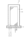
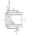
- Fig. 2 illustrates the cell stack structure.
- the cell stack 110 is installed on the support base 111 and extends upward.
- the periphery of the cell stack 112 is covered with a cylindrical cover 113 that is applied from above.
- the reformed gas and air are introduced from the lower part of the cell stack 112 and distributed to each single cell so as to spread evenly throughout.
- the reformed gas and air distributed to each single cell undergo a chemical reaction with each other and change in quality to become an anode off-gas and a cathode off-gas.
- the anode off-gas is collected through a predetermined path, and the cathode off-gas is collected through a gap between the cell stack 112 and the cover 113.
- the recovered anode off-gas and cathode off-gas are led out from the lower part of the cell stack 110, sent to a burner, and used as combustion fuel.
- an object of the present invention is to provide a fuel cell including a stacked cell stack that can cool the entire cell stack in a balanced manner.
- the disclosed fuel cell is a solid oxide fuel cell.
- the fuel cell includes a cell stack made of a solid electrolyte in which an anode electrode and a cathode electrode are formed, a reformed gas introduction path for introducing a reformed gas mainly containing hydrogen into the cell stack, and an oxidant gas in the cell.
- a heat absorbing part for absorbing heat is provided around the cell stack.
- the cooling gas introduction path is connected to the oxidant gas introduction path via the heat absorption part.
- an endothermic part that absorbs heat is provided around the cell stack, and the cooling gas merges with the oxidant gas via the endothermic part.
- the heat absorbing portion when the heat absorbing portion is disposed at the high temperature portion of the cell stack when the cell stack is cooled, the high temperature portion can be cooled by the heat absorption of the cooling gas, so that the entire cell stack can be cooled in a well-balanced manner.
- the periphery of the cell stack is covered with a cylindrical cover extending along the cell stack.
- the cell stack has its lower end supported by a support base and extends vertically upward.
- An introduction part for introducing reformed gas and oxidant gas is provided at the lower end of the cell stack, and the heat absorption part is provided around the upper part of the cell stack.
- the introduction portion is provided at the lower end of the cell stack, the lower side of the cell stack is easily cooled, whereas the upper side of the cell stack is particularly biased due to the heat generation of the single cell or the rise of hot air. High temperature. Therefore, although the cell stack tends to cause a temperature difference, since the heat absorption part is provided around the upper part of the cell stack, the upper part of the cell stack can be effectively cooled by the heat absorption of the cooling gas. Therefore, the whole cell stack can be cooled with good balance.
- the heat absorption part is provided in the upper middle stage but not in the uppermost upper stage.
- the heat absorption part is composed of a metal tube arranged in a space around the cell stack.
- the cooling gas can absorb the radiant heat radiated from the cell stack through the metal tube, and thus can effectively absorb heat.
- the metal tube is preferably arranged in a spiral shape around the cell stack.
- the heat transfer surface acting on the heat absorption of the cooling gas can be made long and wide, and the radiant heat can be absorbed more effectively.
- the inlet side of the metal tube is located farther from the introduction part than the outlet side.
- the entire cell stack can be cooled in a well-balanced manner, and efficient and stable power generation can be realized.
- FIG. 6 is a view corresponding to FIG. 5 showing a modification of the fuel cell of the embodiment. It is a graph which shows the temperature change according to the site
- FIG. 3 illustrates a solid oxide fuel cell 1 (SOFC) to which the present invention is applied.
- SOFC solid oxide fuel cell 1
- the basic configuration of the fuel cell 1 is not significantly different from the fuel cell 101 shown in FIG.
- the fuel cell 1 is provided with an evaporator 2, an air preheater 3, a reformer 4, a burner 5, a cell stack 6, and the like, and uses fuel gas such as city gas, water, and oxidant gas. Then, the electromotive force is taken out from the cell stack 6 to generate power.
- fuel gas such as city gas, water, and oxidant gas.
- a gas containing a predetermined amount of oxygen can be used.
- air can be used at a low cost.
- the oxidant gas is not limited to air, and any gas containing oxygen can be used as appropriate.
- the evaporator 2 heats water and generates water vapor.
- the generated water vapor is mixed with fuel gas that has been subjected to a treatment such as desulfurization and sent to the reformer 4.
- the mixed gas of fuel gas and water vapor is reformed into a gas mainly containing hydrogen (reformed gas) in the reformer 4 and introduced into the cell stack 6 through the reaction gas introduction path 10.
- the air preheater 3 heats the outside air and generates a high-temperature oxidant gas (heated oxidant gas).
- the generated heated oxidant gas is introduced into the cell stack 6 through the oxidant gas introduction path 11.
- the high-temperature reformed gas (anode offgas) that has been altered in the cell stack 6 is sent to the burner 5 through the anode-side discharge path 12.
- the heated oxidant gas (cathode off-gas) altered in the cell stack 6 is sent to the burner 5 through the cathode side discharge path 13.
- the anode off gas Since surplus fuel is contained in the anode off gas, the anode off gas is burned by being mixed with the cathode off gas by the burner 5, and the reformer 4 is heated.
- the exhaust gas generated in the burner 5 is sent to the air preheater 3 to heat the oxidant gas and then discharged.
- the air preheater 3 is bypassed to the oxidant gas introduction path 11 via the air preheater 3.
- a cooling gas introduction path 14 is also provided.
- the upstream end portion of the cooling gas introduction path 14 is connected to a branch portion 15 provided at a portion upstream of the air preheater 3 in the oxidant gas introduction path 11, and from there
- the cooling gas introduction path 14 is branched.
- the downstream end of the cooling gas introduction path 14 is connected to a merging portion 16 provided in a portion downstream of the air preheater 3 in the oxidant gas introduction path 11, and the cooling gas introduction path 14 is provided there. Have joined.
- a flow rate control valve 17 capable of adjusting the flow rate of the cooling gas flowing through the cooling gas introduction path 14 is installed.
- the fuel cell 1 is devised so that the temperature difference of the cell stack 6 can be eliminated by using the cooling gas flowing through the cooling gas introduction path 14.
- the cooling gas since the cooling gas finally merges with the air as the oxidant gas, it may be a gas that does not contain oxygen, such as nitrogen.
- the mixed gas after joining may be a gas that does not adversely affect power generation. For example, air is easy to handle because it has the same composition as the oxidant gas.
- the cell stack 6 is a so-called stacked type.
- the cell stack 6 includes a cell stack 21, a cover 31, and the like, and is vertically placed on the support base 22.
- the cell stack 21 is disposed inside the cover 31, and a lower end thereof is supported by the support base 22 and extends vertically upward.
- the cell laminate 21 is configured so as to extend in the plate thickness direction by laminating a large number of thin plate-like single cells 21a with the interconnector interposed therebetween, as in the conventional product.
- Each single cell 21a has a solid electrolyte made of yttria stabilized zirconia or the like.
- An anode electrode is formed on one surface of the solid electrolyte, and a cathode electrode is formed on the other surface.
- anode side reaction gaps and cathode side reaction gaps are alternately formed (not shown).
- the stacked unit cells 21a are integrally supported by a support rod 23, a pressing plate 24, and the like.
- a plurality of support rods 23 are provided on the support base 22 so as to surround the cell stack 21 and extend upward in the vertical direction.
- a pressing plate 24 is placed on the upper end surface of the cell stack 21.
- a support plate 25 is fastened and attached to the upper end portion of the support rod 23 protruding upward from the presser plate 24.
- a spring member 26 is installed on the lower surface of the support plate 25, and the support plate 25 presses the pressing plate 24 downward through the spring member 26. Thereby, the stacked single cells 21 a are pressure-bonded by the support base 22 and the pressing plate 24.
- the cover 31 has a cylindrical side wall portion 31a that is slightly larger than the cell stack 21, an end wall portion 31b that closes the opening at the upper end of the side wall portion 31a, and an annular shape that projects outward from the lower end edge of the side wall portion 31a. And a flange portion 31c.
- a large-diameter portion 32 having a relatively large diameter and bulging radially outward is formed in a certain region in the upper portion of the side wall portion 31a.
- the cover 31 is attached to the support base 22 by fastening the flange portion 31c in a state of covering the cell laminate 21.
- the cover 31 extends in the vertical direction along the cell stack 21. Thereby, a gap space 33 with a constant interval is formed between the side surface of the cell stack 21 and the inner surface of the side wall portion 31a.
- a larger space is formed between the upper portion of the side surface of the cell stack 21 and the inner surface of the large diameter portion 32.
- a metal tube 61 is installed in the heat absorbing space 34, which will be described later.
- the anode-side and cathode-side intake manifolds 41 and 42 and the exhaust manifold 43 are formed so as to extend in the stacking direction.
- the anode side reaction gap of each single cell 21 a communicates with the anode side intake manifold 41 and the exhaust manifold 43.
- the cathode side reaction gap communicates with the cathode side intake manifold 42 and the gap space 33.
- the anode side intake manifold 41 has an anode side introduction port 44 (introduction portion) at the lower end surface of the cell stack 21, and the cathode side intake manifold 42 has a cathode side introduction port 45 (introduction) at the lower end surface of the cell stack 21. Part).
- the exhaust manifold 43 has an anode outlet 46 on the lower end surface of the cell stack 21.
- the anode side inlet port 44, the cathode side inlet port 45, and the anode side outlet port 46 are adjacent to each other.
- An anode side introduction hole 47, a cathode side introduction hole 48, an anode side lead hole 49, and a cathode side lead hole 50 are opened on the upper surface of the support base 22.
- the anode side introduction hole 47 communicates with the anode side intake manifold 41 through the anode side introduction port 44.
- the cathode side introduction hole 48 communicates with the cathode side intake manifold 42 through the cathode side introduction port 45.
- the anode side outlet hole 49 communicates with the exhaust manifold 43 through the anode side outlet 46.
- the cathode side outlet hole 50 communicates with the gap space 33.
- the downstream end of the reaction gas introduction path 10 is connected to the anode introduction hole 47.
- the cathode side introduction hole 48 is connected to the downstream end of the oxidant gas introduction path 11.
- An upstream end of the anode discharge path 12 is connected to the anode outlet hole 49.
- the cathode side outlet hole 50 is connected to the upstream end of the cathode side discharge path 13.
- each cathode-side reaction space has a cathode-side introduction hole 48 and a cathode-side intake manifold 42.
- heated oxidant gas is introduced.
- the cell stack 21 is heated using the reformed gas and the heated oxidant gas as heat sources.
- An electromotive force is generated in each single cell 21a due to a chemical reaction. Electric power is generated by extracting the electromotive force. Usually, power generation is possible at 700 ° C. to 900 ° C. However, since efficient power generation is performed at around 800 ° C., the entire cell stack 21 is preferably kept at around 800 ° C.
- each single cell 21a Since each single cell 21a generates heat due to a chemical reaction, in this fuel cell 1, in order to maintain it in a predetermined operating temperature range during steady operation, the temperature of the heated oxidant gas is lowered to appropriately cool the cell stack 21. Cooling control is performed.
- the merging portion 16 is disposed at a site in the vicinity of the cathode side introduction hole 48 in the oxidant gas introduction path 11, and the cooling gas merges with the heated oxidant gas and is mixed therewith, The temperature of the heated oxidant gas is lowered. The temperature of the heated oxidant gas is controlled by adjusting the flow rate of the cooling gas.
- the cooling gas introduction path 14 is a metal disposed in the heat absorbing space 34 so that the entire cell stack 21 can be cooled in a balanced manner by using the features of the stacked cell stack 6. It is connected to the merging portion 16 via a pipe 61 (heat absorbing portion).
- the metal tube 61 is formed in a spiral shape using a metal having excellent thermal conductivity, and is accommodated in the heat absorbing space 34.
- the metal tube 61 is disposed around the upper portion of the cell stack 21 and faces the cell stack 21 with a gap.
- the metal tube 61 is provided so as to surround the periphery of the cell stack 21 and further to spirally surround the periphery of the cell stack 21.
- the term “enclose” as used herein includes what is provided so as to surround at least a half circumference.
- an upstream connection portion 62 to which one end of the metal tube 61 is connected is installed on the upper side of the large diameter portion 32, and a downstream side to which the other end of the metal tube 61 is connected to the lower side of the large diameter portion 32.
- a side connection 63 is installed.
- the metal tube 61 is fixed inside the cover 31.
- insulation between the metal tube 61 and the cell stack 6 is necessary.
- the metal tube 61 is not contacted. Thus, no insulation is required, and positioning can be performed while maintaining the optimum heat absorbing space 34.
- the metal tube 61 can be positioned at a predetermined position with respect to the cell stack 6, and the cover 31 can be covered later.
- the downstream end portion of the cooling gas introduction path 14 extending from the branch portion 15 is connected to the upstream connection portion 62 and communicates with the metal pipe 61.
- An upstream end portion of the cooling gas introduction path 14 extending from the merging portion 16 is connected to the downstream connection portion 63 and communicates with the metal pipe 61. Accordingly, the cooling gas flows into the metal pipe 61 from the upstream connection portion 62 and flows out from the downstream connection portion 63.
- the flow rate control valve 17 When the control for lowering the temperature of the cell stack 21 is activated during steady operation, the flow rate control valve 17 is activated and the flow rate of the cooling gas is increased. Thereby, the temperature of the heated oxidant gas introduced into the cell stack 21 is lowered. Since the heated oxidant gas whose temperature has been lowered is introduced from the lower end of the cell stack 21, it is cooled in order from the single cell 21a located on the lower side of the cell stack 21, and as the cathode side intake manifold 42 rises, the heated oxidant The temperature of the gas becomes higher.
- the upper portion of the cell stack 6 is likely to become high temperature due to the rise of hot air, and each single cell 21a generates heat and the heat is also added to the heated oxidant gas. As a result, the cooling of the upper part of the cell stack 21 may be insufficient.
- the cooling gas is not directly joined to the heated oxidant gas, but is joined after passing through the metal pipe 61. Since the metal tube 61 is disposed in the heat absorbing space 34 provided around the upper portion of the cell stack 21, it effectively absorbs the radiant heat emitted from the cell stack 21. Therefore, since the cooling gas absorbs the heat of the upper part of the cell stack 21 while passing through the metal tube 61, the temperature of the upper part of the cell stack 21 is relatively lowered.
- the cooling gas circulates from the upper side to the lower side of the cell stack 6 and the metal tube 61 is arranged so as to flow a long distance from the high temperature side, so that the radiant heat is efficiently absorbed. Even if the temperature of the cooling gas rises due to heat absorption, it does not rise above the temperature of the heated oxidant gas, so that the original cooling function of the cooling gas is not lost.
- the cooling gas is mixed with the heated oxidant gas at the junction 16, and the heated oxidant gas having a lowered temperature is introduced into the cell stack 21.
- the temperature drop of the heated oxidant gas introduced into the cell stack 21 is reduced by the increase in the temperature of the cooling gas as compared with the conventional fuel cell, the single cell located below the cell stack 21 21a is gently cooled.
- the upper part of the cell stack 21 is cooled by the absorption of radiant heat by the cooling gas, and the lower part of the cell stack 21 is the cooling gas whose temperature is increased by the endotherm of the upper part of the cell stack 21. Therefore, even in the stacked cell stack 6, the entire cell stack 21 can be cooled in a well-balanced manner.
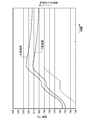
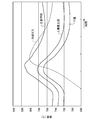
- FIG. 7 shows the test results of the comparative example.
- the fuel cell of the comparative example has a conventional configuration as shown in FIGS. 1 and 2, and the periphery of the cell stack is simply covered with a cover so that the cooling gas is directly mixed with the heated oxidant gas. It has become.
- FIG. 7 shows a temperature state immediately before starting steady operation.
- the lower solid line indicates the temperature change in the lower part of the cell stack
- the upper solid line indicates the temperature change in the upper part of the cell stack.
- a broken line indicates a change in the flow rate of the cooling gas.
- a temperature difference of 20 ° C. or more was observed above and below the cell stack before the introduction of the cooling gas. Furthermore, when the flow rate of the cooling gas is increased in response to the temperature rise at the top of the cell stack, the temperature at the bottom of the cell stack begins to decrease, and the temperature difference tends to increase between the top and bottom of the cell stack. It was.
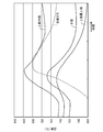
- FIG. 8 shows the test results of the examples.
- the fuel cell of the example has the configuration shown in FIGS. In addition, it is set so that it may become the same conditions as a comparative example except structures, such as a cooling gas introduction path
- FIG. 8 shows a temperature change in a steady operation state where the temperature is set to be higher as a test.
- the lower solid line indicates the temperature change in the lower part of the cell stack
- the upper solid line indicates the temperature change in the upper part of the cell stack
- the broken line indicates the change in the flow rate of the cooling gas.
- a temperature difference of about 5 ° C. was observed above and below the cell stack before the introduction of the cooling gas.
- the temperature of the upper and lower portions of the cell stack increased while maintaining substantially the same temperature difference, and there was no tendency for the temperature difference to expand above and below the cell stack.
- the temperature at the top and bottom of the cell stack began to drop at approximately the same timing around 820 ° C.
- the temperature difference at that time was about 10 ° C.
- the temperature of the upper and lower parts of the cell stack gradually decreases while maintaining a temperature difference of about 10 ° C., and converges to around 800 ° C. A trend was observed. Therefore, it was confirmed that the entire cell stack could be maintained at an optimum operating temperature of around 800 ° C., and stable power generation could be realized.
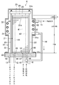
- FIG. 9 shows a modification of the fuel cell 1 described above.
- the fuel cell of this modification is different from the above-described fuel cell 1 in the positions of the large diameter portion 32, the metal pipe 61, and the heat absorbing space 34.
- the position of the large diameter portion 32 or the like is provided up to the uppermost part (upper uppermost stage) of the cell stack 21.
- the large-diameter portion 32 and the like are arranged in this way, a temperature difference between the uppermost upper stage and the lower part tends to increase with time.
- the upper uppermost part was measured as an upper example, but when the temperature of the upper middle stage was measured, a tendency that the temperature was higher than that of the upper uppermost part was recognized. For this reason, when the flow rate of the cooling gas was adjusted to cool this, there was a tendency for the upper part (upper uppermost stage) to be too cold and to cause problems below the lower part.
- FIG. 10 is a graph showing the change, and the broken line shows the change in the flow rate of the cooling gas.
- the large-diameter portion 32 or the like is provided up to the uppermost upper stage, the upper uppermost stage is too cold and reverses the temperature of the lower part on the way, and the temperature difference between the upper uppermost stage and the lower part with time elapses. A tendency to spread was recognized.
- the large-diameter portion 32 or the like when the position of the large-diameter portion 32 or the like is shifted downward and the upper portions are the “upper upper stage” and the “upper middle stage”, the large-diameter portion 32 or the like is As shown in the graph of FIG. 11, the temperature difference between the uppermost upper stage and the lower part does not spread over time.
- the entire cell stack 21 can be cooled in a balanced manner regardless of the passage of time, and more efficient and stable power generation can be realized.
- the fuel cell according to the present invention is not limited to the above-described embodiment, and includes various other configurations.
- the structure of the heat absorption part is not limited to a spiral metal pipe.
- a double tube structure may be provided on the upper portion of the cover 31 to form an annular space 70 in which the cooling gas flows along the periphery of the cell stack.
- the heat absorption part should just be provided in the site
- the heat absorption portion may be provided around the lower portion of the cell stack 21.
- the heat absorption part may be provided around either or both of the upper part and the lower part of the cell stack 21.
- the cell stack 6 is not limited to being placed vertically, but may be placed horizontally.
- the cell stack is not limited to the stacked cell stack, and may be a cell stack composed of, for example, a cylindrical cell tube.
- the cell stack composed of such cylindrical cell tubes is specifically composed as follows.
- a cylindrical cell body and electrode terminals connected to both ends of the cell body are provided. Inside the cell main body, a cylindrical inner electrode layer and an outer electrode layer, and an electrolyte layer between them are provided.
- the inner electrode layer is a fuel electrode
- the outer electrode layer is an air electrode.
- the inner electrode layer is electrically connected to the electrode terminal.
- a fuel gas flow path is formed at the center of the electrode terminal.
Landscapes
- Engineering & Computer Science (AREA)
- Chemical & Material Sciences (AREA)
- Life Sciences & Earth Sciences (AREA)
- Manufacturing & Machinery (AREA)
- Sustainable Development (AREA)
- Sustainable Energy (AREA)
- Chemical Kinetics & Catalysis (AREA)
- Electrochemistry (AREA)
- General Chemical & Material Sciences (AREA)
- Combustion & Propulsion (AREA)
- Fuel Cell (AREA)
Abstract
Description
図3に、本発明を適用した固体酸化物形の燃料電池1(SOFC)を例示する。燃料電池1の基本的構成は、図1に示した燃料電池101と大差は無い。
図4及び図5に、この燃料電池1のセルスタック6を示す。このセルスタック6は、いわゆる積層型である。セルスタック6は、セル積層体21やカバー31などで構成されており、支持台22の上に縦置きされている。セル積層体21は、カバー31の内部に配置され、その下端が支持台22に支持されて鉛直方向を上向きに延びている。
図7及び図8に、試験装置による実証試験の結果を示す。
図9に、上述した燃料電池1の変形例を示す。本変形例の燃料電池は、大径部32や金属管61、吸熱スペース34の位置が上述した燃料電池1と異なっている。
なお、本発明にかかる燃料電池は、上述した実施形態に限定されず、それ以外の種々の構成をも包含する。
6 セルスタック
10 反応ガス導入経路
11 酸化剤ガス導入経路
12 アノード側排出経路
13 カソード側排出経路
14 冷却ガス導入経路
21 セル積層体
21a 単セル
22 支持台
23 支持ロッド
31 カバー
32 大径部
34 吸熱スペース
41 アノード側吸気マニホールド
42 カソード側吸気マニホールド
43 排気マニホールド
44 アノード側導入口(導入部)
45 カソード側導入口(導入部)
61 金属管
62 上流側接続部
63 下流側接続部
Claims (6)
- 固体酸化物形の燃料電池であって、
アノード電極ならびにカソード電極が形成された固体電解質からなるセルスタックと、
水素を主とする改質ガスを前記セルスタックに導入する改質ガス導入経路と、
酸化剤ガスを前記セルスタックに導入する酸化剤ガス導入経路と、
前記酸化剤ガスの温度を下げる冷却ガスを前記酸化剤ガス導入経路に導入する冷却ガス導入経路と、
を備え、
前記セルスタックの周囲に、熱を吸収する吸熱部が設けられ、
前記冷却ガス導入経路が、前記吸熱部を経由して前記酸化剤ガス導入経路に接続されている燃料電池。 - 請求項1に記載の燃料電池において、
前記セルスタックの周囲が、当該セルスタックに沿って延びる筒状のカバーで覆われている燃料電池。 - 請求項1又は請求項2に記載の燃料電池において、
前記セルスタックは、その下端が支持台に支持されて鉛直方向を上向きに延びており、
前記改質ガス及び酸化剤ガスを導入する導入部が前記セルスタックの下端部に設けられ、前記吸熱部が当該セルスタックの上部の周囲に設けられている燃料電池。 - 請求項3に記載の燃料電池において、
前記セルスタックの上部が上部最上段とその下方に位置する上部中段から構成されるとき、前記吸熱部は、前記上部中段に設けられて前記上部最上段に設けられていない燃料電池。 - 請求項1~請求項4のいずれか一つに記載の燃料電池において、
前記吸熱部が、前記セルスタックの周囲の空間に配置された金属管で構成されている燃料電池。 - 請求項5に記載の燃料電池において、
前記金属管が前記セルスタックの周囲に螺旋状に配置されている燃料電池。
Priority Applications (4)
| Application Number | Priority Date | Filing Date | Title |
|---|---|---|---|
| JP2015507982A JP6177881B2 (ja) | 2013-03-25 | 2014-02-05 | 燃料電池 |
| US14/771,193 US9666890B2 (en) | 2013-03-25 | 2014-02-05 | Fuel cell |
| CN201480011896.1A CN105009338B (zh) | 2013-03-25 | 2014-02-05 | 燃料电池 |
| EP14773527.8A EP2950377B1 (en) | 2013-03-25 | 2014-02-05 | Fuel cell |
Applications Claiming Priority (2)
| Application Number | Priority Date | Filing Date | Title |
|---|---|---|---|
| JP2013061858 | 2013-03-25 | ||
| JP2013-061858 | 2013-03-25 |
Publications (1)
| Publication Number | Publication Date |
|---|---|
| WO2014155928A1 true WO2014155928A1 (ja) | 2014-10-02 |
Family
ID=51622954
Family Applications (1)
| Application Number | Title | Priority Date | Filing Date |
|---|---|---|---|
| PCT/JP2014/000607 Ceased WO2014155928A1 (ja) | 2013-03-25 | 2014-02-05 | 燃料電池 |
Country Status (5)
| Country | Link |
|---|---|
| US (1) | US9666890B2 (ja) |
| EP (1) | EP2950377B1 (ja) |
| JP (2) | JP6177881B2 (ja) |
| CN (1) | CN105009338B (ja) |
| WO (1) | WO2014155928A1 (ja) |
Cited By (3)
| Publication number | Priority date | Publication date | Assignee | Title |
|---|---|---|---|---|
| JP2015216011A (ja) * | 2014-05-09 | 2015-12-03 | 東京瓦斯株式会社 | ホットモジュール |
| JP2016171016A (ja) * | 2015-03-13 | 2016-09-23 | 富士電機株式会社 | 固体酸化物形燃料電池モジュール |
| JP2019536243A (ja) * | 2016-11-29 | 2019-12-12 | アーファオエル・リスト・ゲーエムベーハー | 燃料電池システム |
Families Citing this family (6)
| Publication number | Priority date | Publication date | Assignee | Title |
|---|---|---|---|---|
| EP3130174B1 (en) | 2014-04-07 | 2020-03-04 | InterDigital CE Patent Holdings | Method of controlling handover in mobile communication networks and apparatus implementing the method |
| JP2017183222A (ja) * | 2016-03-31 | 2017-10-05 | 本田技研工業株式会社 | 燃料電池システム |
| FR3087952B1 (fr) * | 2018-10-26 | 2021-09-24 | Commissariat Energie Atomique | Systeme electrochimique a oxydes solides a moyens de chauffage integres |
| CN112397743B (zh) * | 2019-08-14 | 2024-10-22 | 全球能源互联网研究院有限公司 | 一种固体氧化物燃料电池连接体 |
| JP7329396B2 (ja) * | 2019-09-11 | 2023-08-18 | 日産自動車株式会社 | 燃料電池スタック |
| WO2021090041A1 (ja) * | 2019-11-07 | 2021-05-14 | 日産自動車株式会社 | 燃料電池システム |
Citations (4)
| Publication number | Priority date | Publication date | Assignee | Title |
|---|---|---|---|---|
| JPH097624A (ja) * | 1995-06-19 | 1997-01-10 | Mitsubishi Heavy Ind Ltd | 固体電解質型燃料電池 |
| JP2002260697A (ja) * | 2000-12-28 | 2002-09-13 | Mitsubishi Materials Corp | 燃料電池モジュール |
| JP2009238623A (ja) | 2008-03-27 | 2009-10-15 | Hitachi Ltd | 固体酸化物形燃料電池発電システムとその運転制御方法 |
| JP2011065909A (ja) | 2009-09-18 | 2011-03-31 | Sumitomo Precision Prod Co Ltd | 積層型燃料電池 |
Family Cites Families (13)
| Publication number | Priority date | Publication date | Assignee | Title |
|---|---|---|---|---|
| US6033793A (en) * | 1996-11-01 | 2000-03-07 | Hydrogen Burner Technology, Inc. | Integrated power module |
| WO2002054519A1 (en) * | 2000-12-28 | 2002-07-11 | Mitsubishi Materials Corporation | Fuel cell module and structure for gas supply to fuel cell |
| US6756144B2 (en) * | 2002-01-03 | 2004-06-29 | Hybrid Power Generation Systems, Llc | Integrated recuperation loop in fuel cell stack |
| GB0213561D0 (en) * | 2002-06-13 | 2002-07-24 | Alstom | Fuel cells |
| JP2005078859A (ja) | 2003-08-28 | 2005-03-24 | Mitsubishi Heavy Ind Ltd | 燃料電池システム |
| JP4461955B2 (ja) * | 2004-08-13 | 2010-05-12 | 三菱マテリアル株式会社 | 固体酸化物形燃料電池 |
| JP2007287633A (ja) * | 2006-04-20 | 2007-11-01 | Mitsubishi Materials Corp | 燃料電池発電装置及び制御プログラム並びに制御方法 |
| JP5242933B2 (ja) * | 2007-03-30 | 2013-07-24 | 東邦瓦斯株式会社 | 燃料電池モジュール |
| JP2009054414A (ja) * | 2007-08-27 | 2009-03-12 | Mitsubishi Materials Corp | 燃料電池スタック |
| JP5185658B2 (ja) | 2008-02-27 | 2013-04-17 | 三菱重工業株式会社 | コンバインドシステム |
| JP5349251B2 (ja) | 2009-10-26 | 2013-11-20 | トヨタ自動車株式会社 | 燃料電池システム |
| JP5409333B2 (ja) | 2009-12-24 | 2014-02-05 | 京セラ株式会社 | 燃料電池モジュールおよび燃料電池装置 |
| KR20120080881A (ko) * | 2011-01-10 | 2012-07-18 | 삼성에스디아이 주식회사 | 연료 전지 시스템 및 연료 전지 내에서의 연료의 반응 조건을 제어하는 방법 |
-
2014
- 2014-02-05 EP EP14773527.8A patent/EP2950377B1/en active Active
- 2014-02-05 US US14/771,193 patent/US9666890B2/en active Active
- 2014-02-05 WO PCT/JP2014/000607 patent/WO2014155928A1/ja not_active Ceased
- 2014-02-05 CN CN201480011896.1A patent/CN105009338B/zh active Active
- 2014-02-05 JP JP2015507982A patent/JP6177881B2/ja active Active
-
2017
- 2017-07-12 JP JP2017136243A patent/JP2017212215A/ja active Pending
Patent Citations (4)
| Publication number | Priority date | Publication date | Assignee | Title |
|---|---|---|---|---|
| JPH097624A (ja) * | 1995-06-19 | 1997-01-10 | Mitsubishi Heavy Ind Ltd | 固体電解質型燃料電池 |
| JP2002260697A (ja) * | 2000-12-28 | 2002-09-13 | Mitsubishi Materials Corp | 燃料電池モジュール |
| JP2009238623A (ja) | 2008-03-27 | 2009-10-15 | Hitachi Ltd | 固体酸化物形燃料電池発電システムとその運転制御方法 |
| JP2011065909A (ja) | 2009-09-18 | 2011-03-31 | Sumitomo Precision Prod Co Ltd | 積層型燃料電池 |
Cited By (4)
| Publication number | Priority date | Publication date | Assignee | Title |
|---|---|---|---|---|
| JP2015216011A (ja) * | 2014-05-09 | 2015-12-03 | 東京瓦斯株式会社 | ホットモジュール |
| JP2016171016A (ja) * | 2015-03-13 | 2016-09-23 | 富士電機株式会社 | 固体酸化物形燃料電池モジュール |
| JP2019536243A (ja) * | 2016-11-29 | 2019-12-12 | アーファオエル・リスト・ゲーエムベーハー | 燃料電池システム |
| JP7062007B2 (ja) | 2016-11-29 | 2022-05-02 | アーファオエル・リスト・ゲーエムベーハー | 燃料電池システム |
Also Published As
| Publication number | Publication date |
|---|---|
| US9666890B2 (en) | 2017-05-30 |
| US20160013501A1 (en) | 2016-01-14 |
| JP6177881B2 (ja) | 2017-08-09 |
| CN105009338A (zh) | 2015-10-28 |
| JP2017212215A (ja) | 2017-11-30 |
| CN105009338B (zh) | 2017-05-17 |
| EP2950377B1 (en) | 2017-11-29 |
| EP2950377A1 (en) | 2015-12-02 |
| EP2950377A4 (en) | 2016-01-13 |
| JPWO2014155928A1 (ja) | 2017-02-16 |
Similar Documents
| Publication | Publication Date | Title |
|---|---|---|
| JP6177881B2 (ja) | 燃料電池 | |
| JP5065367B2 (ja) | 燃料電池モジュール | |
| US8178256B2 (en) | Fuel cell system | |
| US8597842B2 (en) | Fuel cell module | |
| JP6101781B2 (ja) | 燃料電池モジュール | |
| JP5070885B2 (ja) | 燃料電池 | |
| JP5109252B2 (ja) | 燃料電池 | |
| JP6111904B2 (ja) | 燃料電池装置 | |
| JP5122319B2 (ja) | 固体酸化物形燃料電池 | |
| JP5109253B2 (ja) | 燃料電池 | |
| JP6429019B2 (ja) | 固体酸化物形燃料電池装置 | |
| JP5643711B2 (ja) | 燃料電池モジュール | |
| JP2019220370A (ja) | 燃料電池モジュール | |
| US8603691B2 (en) | Fuel cell system with rotation mechanism | |
| JP2016139554A (ja) | 固体酸化物形燃料電池装置 | |
| JP2012124070A (ja) | 固体酸化物型燃料電池 | |
| JP2009245627A (ja) | 固体酸化物形燃料電池 | |
| JP2007026928A (ja) | 燃料電池 | |
| KR101316042B1 (ko) | 연료전지용 통합형 개질기 시스템 | |
| JP2016139555A (ja) | 固体酸化物形燃料電池装置 | |
| JP5044921B2 (ja) | 燃料電池モジュールおよび運転方法 | |
| JP2011210570A (ja) | 燃料電池モジュール | |
| JP2005294000A (ja) | 固体電解質型燃料電池 |
Legal Events
| Date | Code | Title | Description |
|---|---|---|---|
| 121 | Ep: the epo has been informed by wipo that ep was designated in this application |
Ref document number: 14773527 Country of ref document: EP Kind code of ref document: A1 |
|
| ENP | Entry into the national phase |
Ref document number: 2015507982 Country of ref document: JP Kind code of ref document: A |
|
| WWE | Wipo information: entry into national phase |
Ref document number: 14771193 Country of ref document: US |
|
| REEP | Request for entry into the european phase |
Ref document number: 2014773527 Country of ref document: EP |
|
| WWE | Wipo information: entry into national phase |
Ref document number: 2014773527 Country of ref document: EP |
|
| NENP | Non-entry into the national phase |
Ref country code: DE |