WO2014156010A1 - 誘導加熱調理器 - Google Patents
誘導加熱調理器 Download PDFInfo
- Publication number
- WO2014156010A1 WO2014156010A1 PCT/JP2014/001342 JP2014001342W WO2014156010A1 WO 2014156010 A1 WO2014156010 A1 WO 2014156010A1 JP 2014001342 W JP2014001342 W JP 2014001342W WO 2014156010 A1 WO2014156010 A1 WO 2014156010A1
- Authority
- WO
- WIPO (PCT)
- Prior art keywords
- heating coil
- coil unit
- outer shell
- induction heating
- support member
- Prior art date
- Legal status (The legal status is an assumption and is not a legal conclusion. Google has not performed a legal analysis and makes no representation as to the accuracy of the status listed.)
- Ceased
Links
Images








Classifications
-
- H—ELECTRICITY
- H05—ELECTRIC TECHNIQUES NOT OTHERWISE PROVIDED FOR
- H05B—ELECTRIC HEATING; ELECTRIC LIGHT SOURCES NOT OTHERWISE PROVIDED FOR; CIRCUIT ARRANGEMENTS FOR ELECTRIC LIGHT SOURCES, IN GENERAL
- H05B6/00—Heating by electric, magnetic or electromagnetic fields
- H05B6/02—Induction heating
- H05B6/10—Induction heating apparatus, other than furnaces, for specific applications
- H05B6/12—Cooking devices
- H05B6/1209—Cooking devices induction cooking plates or the like and devices to be used in combination with them
-
- H—ELECTRICITY
- H05—ELECTRIC TECHNIQUES NOT OTHERWISE PROVIDED FOR
- H05B—ELECTRIC HEATING; ELECTRIC LIGHT SOURCES NOT OTHERWISE PROVIDED FOR; CIRCUIT ARRANGEMENTS FOR ELECTRIC LIGHT SOURCES, IN GENERAL
- H05B6/00—Heating by electric, magnetic or electromagnetic fields
- H05B6/02—Induction heating
- H05B6/10—Induction heating apparatus, other than furnaces, for specific applications
- H05B6/12—Cooking devices
- H05B6/1209—Cooking devices induction cooking plates or the like and devices to be used in combination with them
- H05B6/1245—Cooking devices induction cooking plates or the like and devices to be used in combination with them with special coil arrangements
-
- H—ELECTRICITY
- H05—ELECTRIC TECHNIQUES NOT OTHERWISE PROVIDED FOR
- H05B—ELECTRIC HEATING; ELECTRIC LIGHT SOURCES NOT OTHERWISE PROVIDED FOR; CIRCUIT ARRANGEMENTS FOR ELECTRIC LIGHT SOURCES, IN GENERAL
- H05B6/00—Heating by electric, magnetic or electromagnetic fields
- H05B6/02—Induction heating
- H05B6/10—Induction heating apparatus, other than furnaces, for specific applications
- H05B6/12—Cooking devices
- H05B6/1209—Cooking devices induction cooking plates or the like and devices to be used in combination with them
- H05B6/1245—Cooking devices induction cooking plates or the like and devices to be used in combination with them with special coil arrangements
- H05B6/1254—Cooking devices induction cooking plates or the like and devices to be used in combination with them with special coil arrangements using conductive pieces to direct the induced magnetic field
-
- H—ELECTRICITY
- H05—ELECTRIC TECHNIQUES NOT OTHERWISE PROVIDED FOR
- H05B—ELECTRIC HEATING; ELECTRIC LIGHT SOURCES NOT OTHERWISE PROVIDED FOR; CIRCUIT ARRANGEMENTS FOR ELECTRIC LIGHT SOURCES, IN GENERAL
- H05B6/00—Heating by electric, magnetic or electromagnetic fields
- H05B6/02—Induction heating
- H05B6/10—Induction heating apparatus, other than furnaces, for specific applications
- H05B6/12—Cooking devices
- H05B6/1209—Cooking devices induction cooking plates or the like and devices to be used in combination with them
- H05B6/1245—Cooking devices induction cooking plates or the like and devices to be used in combination with them with special coil arrangements
- H05B6/1263—Cooking devices induction cooking plates or the like and devices to be used in combination with them with special coil arrangements using coil cooling arrangements
-
- H—ELECTRICITY
- H05—ELECTRIC TECHNIQUES NOT OTHERWISE PROVIDED FOR
- H05B—ELECTRIC HEATING; ELECTRIC LIGHT SOURCES NOT OTHERWISE PROVIDED FOR; CIRCUIT ARRANGEMENTS FOR ELECTRIC LIGHT SOURCES, IN GENERAL
- H05B2206/00—Aspects relating to heating by electric, magnetic, or electromagnetic fields covered by group H05B6/00
- H05B2206/02—Induction heating
- H05B2206/022—Special supports for the induction coils
-
- H—ELECTRICITY
- H05—ELECTRIC TECHNIQUES NOT OTHERWISE PROVIDED FOR
- H05B—ELECTRIC HEATING; ELECTRIC LIGHT SOURCES NOT OTHERWISE PROVIDED FOR; CIRCUIT ARRANGEMENTS FOR ELECTRIC LIGHT SOURCES, IN GENERAL
- H05B6/00—Heating by electric, magnetic or electromagnetic fields
- H05B6/02—Induction heating
-
- H—ELECTRICITY
- H05—ELECTRIC TECHNIQUES NOT OTHERWISE PROVIDED FOR
- H05B—ELECTRIC HEATING; ELECTRIC LIGHT SOURCES NOT OTHERWISE PROVIDED FOR; CIRCUIT ARRANGEMENTS FOR ELECTRIC LIGHT SOURCES, IN GENERAL
- H05B6/00—Heating by electric, magnetic or electromagnetic fields
- H05B6/02—Induction heating
- H05B6/06—Control, e.g. of temperature, of power
- H05B6/062—Control, e.g. of temperature, of power for cooking plates or the like
-
- Y—GENERAL TAGGING OF NEW TECHNOLOGICAL DEVELOPMENTS; GENERAL TAGGING OF CROSS-SECTIONAL TECHNOLOGIES SPANNING OVER SEVERAL SECTIONS OF THE IPC; TECHNICAL SUBJECTS COVERED BY FORMER USPC CROSS-REFERENCE ART COLLECTIONS [XRACs] AND DIGESTS
- Y02—TECHNOLOGIES OR APPLICATIONS FOR MITIGATION OR ADAPTATION AGAINST CLIMATE CHANGE
- Y02B—CLIMATE CHANGE MITIGATION TECHNOLOGIES RELATED TO BUILDINGS, e.g. HOUSING, HOUSE APPLIANCES OR RELATED END-USER APPLICATIONS
- Y02B40/00—Technologies aiming at improving the efficiency of home appliances, e.g. induction cooking or efficient technologies for refrigerators, freezers or dish washers
Definitions
- the present disclosure relates to an induction heating cooker used for business use or a general home, and particularly relates to a mounting configuration of a heating coil in the induction heating cooker.
- FIG. 23 is a side sectional view of the conventional induction heating cooker described in Patent Document 1 and Patent Document 2.
- a conventional induction heating cooker includes a top plate 101 on which a cooking container that is an object to be heated is placed, a frame 102 that covers a side surface and an upper surface of the outer peripheral edge of the top plate 101, and induction heating cooking. It is comprised by the box which consists of the outer side 103 which comprises the side surface and bottom face of a main body which is a container. Inside the box, a plurality of circuit boards 104 constituting a drive control circuit for supplying a high-frequency current to the heating coil 109 are respectively attached to the board base 105. The substrate bases 105 are stacked and placed and fixed on the bottom surface of the outer shell 103.
- a substrate base cover 106 is provided on the circuit board 104.
- a spring 107 is placed on the substrate base cover 106, and the coil base 108 is supported by the spring 107 while being urged upward from below.
- a heating coil 109 is placed on the coil base 108.
- An anti-vibration rubber 110 is disposed on the coil base 108 in the vicinity of the outer peripheral portion of the heating coil 109.
- An annular rib 111 for positioning is provided on the outer periphery of the portion of the coil base 108 that receives the spring 107, and the upper portion of the spring 107 is fitted inside the rib 111.
- the casing 114 is placed and fixed on the bottom surface of the outer shell 103 while covering the blades 113 attached to the motor 112 and holding the motor 112.
- the main body is arrange
- the spring 107 is provided between the coil base 108 and the substrate base cover 106, and the top plate 101 is attached to the outer shell 103.
- the lower surface of the top plate 101 abuts against the upper surface of the anti-vibration rubber 110 and pushes the coil base 108 downward, so that the spring 107 is compressed.
- the distance between the heating coil 109 placed on the coil base 108 and the top plate 101 can be maintained constant. Therefore, the spring 107 in the induction heating cooker is always in a compressed state.
- the coil base 108 is provided with a rib 111 into which the upper portion of the spring 107 is fitted, thereby preventing the coil base 108 from being displaced in the horizontal direction.
- the spring 107 is provided between the coil base 108 and the substrate base cover 106, the spring 107 has a configuration that presses the anti-vibration rubber 110 attached to the coil base 108 against the back surface of the top plate 101. A constant distance can be secured without changing the distance between the heating coil 109 and the top plate 101.
- the induction heating cooker when the distance between the cooking container, which is an object to be heated placed on the top plate 101, and the heating coil 109 changes, it is generated in an inverter circuit that supplies a high-frequency current to the heating coil 109.
- the high-frequency voltage and high-frequency current to be changed changes, and the product performance as designed cannot be obtained. Therefore, maintaining the distance between the cooking container and the heating coil 109 to be constant without changing is a very important issue in securing the performance of the induction heating cooker.
- the support structure of the induction heating coil needs to support at least three points in order to stably support the substantially circular induction heating coil.
- a rib 111 serving as a spring receiving portion is formed on the substrate base cover 106 that supports the spring 107 and the coil base 108 that receives the spring 107 so that the spring 107 evenly presses the anti-vibration rubber 110 against the top plate 101.
- the back surface of the top plate 101 is usually printed for various purposes.
- a special member made of a soft material such as rubber is necessary to prevent the printing from being scratched, which increases the number of parts and hinders the simplification of the configuration. It was.
- circuit board 104 when the circuit board 104 is to be arranged below the heating coil 109, a member for supporting the spring 107 and its space are required.
- the above-described conventional induction cooking device has a problem that the coil base 108 or the substrate base cover 106 cannot be configured in a simple shape.
- the top plate 101 is constantly subjected to a pressing force from the coil base 108, so that stress is generated and the impact is received. And had the problem of being easily broken.
- This indication is made in view of the above-mentioned subject in the conventional induction heating cooking appliance, eliminates the stress resulting from the pressing force applied from the heating coil unit in the top plate, and the distance between the top plate and the heating coil. It is an object of the present invention to provide an induction heating cooker that can maintain the above constant, further simplify the configuration by reducing the number of parts, reduce the thickness of the main body, and improve the assembly of the main body.
- an induction heating cooker includes: A top plate for placing an object to be heated; An outline having a substantially rectangular opening at the top, formed in a box shape with a bottom surface and side surfaces, and provided with the top plate on the top; A heating coil unit provided inside the outer shell and having a heating coil for induction heating the object to be heated and a heating coil support member for supporting the heating coil; and At least one pair of opposing side surfaces of the outer shell is a first vertical portion formed by bending upward at an outer edge portion of the bottom surface; A first horizontal portion formed by bending outward at the upper edge of the first vertical portion; A second vertical portion that is bent upward at an outer edge portion of the first horizontal portion and forms the opening portion by an upper edge portion, and The heating coil unit is configured to be supported by the first horizontal portion.
- the induction heating cooker according to the present disclosure configured as described above is held by the first vertical portion and the second vertical portion constituting the side surface of the outer shell, and is not easily deformed in the vertical direction. Since the heating coil unit is supported by the portion, the distance between the top plate provided on the upper part of the outer shell and the heating coil can be kept constant.
- the induction heating cooker of the present disclosure eliminates stress due to the pressing force applied from the heating coil unit in the top plate, maintains a constant distance between the top plate and the heating coil, and simplifies the configuration by reducing the number of parts. Further, it is possible to reduce the thickness of the main body and improve the assembly of the main body.
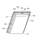
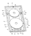
- the perspective view which shows the induction heating cooking appliance which concerns on Embodiment 1 of this indication The perspective view which looked at the top plate unit in the induction heating cooking appliance of Embodiment 1 from the back The perspective view which looked at the state which removed the top plate unit in the induction heating cooking appliance of Embodiment 1 from the bottom. The perspective view which looked at the state which removed the top plate unit in the induction heating cooking appliance of Embodiment 1 from the top.
- the exploded perspective view of the heating coil unit in the induction heating cooking appliance of Embodiment 1 Side surface sectional view which shows the induction heating cooking appliance of Embodiment 1.
- FIG. 1 Side surface sectional view which shows the state which set the induction heating cooking appliance of Embodiment 1 to the kitchen
- the perspective view which looked at the induction heating cooking appliance of Embodiment 2 from the bottom In the induction heating cooking appliance of Embodiment 2 the perspective view which looked at the state which removed the top plate unit from the top
- FIG. Side surface sectional view which shows the induction heating cooking appliance of Embodiment 2.
- FIG. 6 The top view which shows the state which removed the top plate in the induction heating cooking appliance of Embodiment 6.
- FIG. The top view which shows the state which removed the top plate in the other structure of the induction heating cooking appliance of this indication.
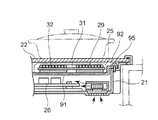
- Side surface sectional drawing which shows the induction heating cooking appliance which concerns on Embodiment 7 of this indication.
- the induction heating cooker includes: A top plate for placing an object to be heated; An outline having a substantially rectangular opening at the top, formed in a box shape with a bottom surface and side surfaces, and provided with the top plate on the top; A heating coil unit provided inside the outer shell and having a heating coil for induction heating the object to be heated and a heating coil support member for supporting the heating coil; and At least one pair of opposing side surfaces of the outer shell is a first vertical portion formed by bending upward at an outer edge portion of the bottom surface; A first horizontal portion formed by bending outward at the upper edge of the first vertical portion; A second vertical portion that is bent upward at an outer edge portion of the first horizontal portion and forms the opening portion by an upper edge portion, and The heating coil unit is configured to be supported by the first horizontal portion.
- the distance between the top plate and the heating coil that is, the distance between the object to be heated and the heating coil greatly affects the electrical performance of the induction heating cooker. Therefore, making the distance constant is one of the important design elements of the induction heating cooker.
- the conventional induction heating cooker it is the structure which mounts and mounts components, such as a heating coil and its supporting member, on the bottom face of an outer shell. For this reason, the conventional induction heating cooker has a structure in which the bottom surface is easily bent and deforms in the vertical direction due to the weight of the components placed on the bottom surface, and the distance between the top plate and the heating coil is easily changed.
- the first horizontal portion of the outer side surface that supports the heating coil unit has a structure that is held by the first vertical portion and the second vertical portion that constitute the outer shell. It has a structure that is difficult to deform in the vertical direction. Since the heating coil unit is supported by the first flat portion, the distance between the top plate provided on the upper part of the outer shell and the heating coil is less likely to change compared to the conventional configuration and is substantially constant. Maintained.
- the heating coil is placed on and supported by the substantially flat heating coil support member, and the vicinity of the end of the heating coil support member is within the outline of the main body. It is configured to be held across the side surface that is difficult to deform with respect to the load in the vertical direction. Since the induction heating cooker of the 1st aspect comprised in this way can reduce the deformation
- the opposing side surfaces of the outer shell in the first aspect are formed by being bent outward or inward at the upper edge of the second vertical part.
- the second horizontal portion is further configured so that the upper surface of the second horizontal portion is in contact with the top plate.
- the induction heating cooker according to the second aspect configured as described above is configured such that the outer peripheral edge of the outer shell is bent outward or inward so as to contact the top plate, thereby preventing fluctuations in the side surface of the outer shell. It becomes the composition to be done. Further, when the outer peripheral edge of the outer shell is bent outward, the outer peripheral edge of the outer shell in the induction heating cooker incorporated in the kitchen is held between the top plate and the kitchen, and the load of the main body is Supported by
- the induction heating cooker according to the third aspect of the present disclosure further includes a heating coil unit support member that supports the heating coil unit in the first or second aspect, and the heating coil unit support member includes: The heating coil unit is fixed to the first horizontal portion, and is configured to be supported by the first horizontal portion via the heating coil unit support member.
- the induction heating cooker of the 3rd aspect comprised as mentioned above is a heating coil unit support member in the shape which cannot be attached to the 1st horizontal part as it is in the 1st or 2nd aspect.
- the heating coil unit can be attached to an appropriate position by being supported by the first horizontal portion.
- the both ends are placed and fixed on the two first horizontal parts facing each other in parallel in the outer shell.
- the heating coil unit is configured to be supported by the first horizontal portion via the joint portion.
- the induction heating cooker of the 4th aspect comprised as mentioned above, by using a joint part, not only the two horizontal parts facing mutually parallel in the side surface of an outline but the side surface arranged at right angles to these It becomes possible to support the heating coil unit by using the horizontal portion. Further, the joint portion can be easily formed into a shape having such a strength that the joint portion is not deformed downward by the weight of the heating coil unit, such as a U-shaped cross section. Thus, since the heating coil unit has the structure supported by the horizontal part and joint part which are hard to deform
- the induction heating cooker of the 5th mode concerning this indication is further provided with the heating coil unit support member which supports the heating coil unit in the 4th mode, and the heating coil unit support member is by the joint part.
- the heating coil unit is supported and supported by the joint portion via the heating coil unit support member.
- the heating coil unit of the shape which cannot attach a joint part to the 1st horizontal part as it is in a 4th aspect is supported by a heating coil unit.
- the heating coil unit can be attached to an appropriate position by supporting the first horizontal portion by the joint portion via the member. For example, by sharing the attachment part to the joint part in a plurality of heating coil units having different shapes, and making the joint part or the heating coil unit support member in a shape corresponding to the heating coil unit of different shape, The heating coil unit is attached to the first horizontal portion via the joint portion and / or the heating coil unit support member.
- the outer shell or the heating coil unit does not have a complicated shape having a plurality of attachment portions, so that an assembly error can be eliminated and an easy-to-assemble product can be provided.
- An induction heating cooker is the third or fifth aspect, in which the heating coil unit support member is in contact with the inner surface of the first vertical portion and protrudes downward.
- a vertical reinforcing wall is provided.
- the strength of the heating coil unit support member can be increased, and it is difficult to bend downward.
- the heating coil unit support member may be bent and deformed downward with the fixing portion of the horizontal portion as a fulcrum.
- the reinforcing coil wall is provided on the heating coil unit support member, the strength of the heating coil unit support member is increased, and it is difficult to bend downward. Yes.
- transformation of a heating coil unit support member can be prevented, and the change of the distance between a heating coil unit and a top plate can be prevented.
- the induction heating cooker according to a seventh aspect of the present disclosure is the first to sixth aspects, wherein the attachment position of the heating coil support member is relative to the first horizontal portion on the opposite side surface of the outer shell. You may comprise so that it can change to the front-back direction or the left-right direction.
- the heating coil in the outer shell can be arranged at an optimum position only by changing the mounting position of the heating coil support member, and variations of products Can be easily deployed.
- a circuit board for driving and controlling the heating coil is provided below the heating coil support member, and the bottom surface of the outer shell is provided. You may comprise so that it may be supported by.
- the member which supports a heating coil and the attachment structure of a heating coil become unnecessary under the heating coil, it is below the heating coil support member.
- a circuit board such as a power supply circuit
- the heating coil support member may be made of a nonmagnetic metal.
- the heating coil supporting member is formed of a nonmagnetic metal such as aluminum, thereby preventing a magnetic metal member adjacent to the back surface of the heating coil from being erroneously heated. It can also serve as a member. For this reason, the space below the heating coil can be reduced, the number of parts can be reduced, and the product can be made thinner, lighter, and reduced in cost.
- induction heating cooker of the present disclosure is not limited to the configuration of the induction heating cooker described in the following embodiment, but a technical idea equivalent to the technical idea described in the following embodiment.
- the apparatus comprised based on is included.
- FIG. 1 is a perspective view showing a main body that is an induction heating cooker according to Embodiment 1 of the present disclosure.
- FIG. 2 is a perspective view of the top plate unit in the induction heating cooker according to the first embodiment as seen from the back.
- FIG. 3 is a perspective view of the main body with the top plate unit removed, as viewed from below, in the induction heating cooker according to the first embodiment.
- FIG. 4 is a perspective view of the main body with the top plate unit removed, as viewed from above, in the induction cooking device of the first embodiment.
- the main body 20 which is the induction heating cooking appliance of Embodiment 1 is provided on the outer shell 21 which has a substantially rectangular parallelepiped shape, and the outer shell 21, and the cooking container which is a to-be-heated object is mounted.
- the top plate 22 is provided.
- an arrow F indicates the front (user side).
- the top plate unit 19 includes a top plate 22, a left side frame 23a, a right side frame 23b, a front frame 24a, and a rear frame 24b.
- a left side frame 23 a extending in the front-rear direction is bonded to the left side of the back surface (lower surface) of the top plate 22, and a right side frame 23 b extending in the front-rear direction is bonded to the right side of the back surface of the top plate 22.
- a front frame 24 a extending in the left-right direction is bonded to the front side of the back surface of the top plate 22, and a rear frame 24 b extending in the left-right direction is bonded to the rear side of the back surface of the top plate 22.
- the left side frame 23a, the right side frame 23a, the front frame 24a, and the rear frame 24b each have a substantially L-shaped cross section orthogonal to the longitudinal direction, and are vertical surfaces that protrude downward from the back surface of the top plate 22 It is adhered to the top plate 22 so as to have Further, each frame 23a, 23b, 24a, 24b is formed with a burring portion subjected to burring for fixing to the outer shell 21. Burring holes 23aa, 23ba, 24aa, 24ba, which are screw holes, are formed in the respective burring portions. Each burring hole 23aa, 23ba, 24aa, 24ba is configured such that a screw 28c (see FIG. 6) passing through a through-hole formed in the outer shell 21 is tightened so that the top plate unit 19 is fixed to the outer shell 21. Has been.
- the outer shell 21 has a substantially rectangular parallelepiped shape, includes a substantially rectangular bottom surface 21a, is bent upward (vertically) at an outer edge portion of the bottom surface 21a, and has a vertical surface.
- the 1st vertical wall 21b which is the vertical part of is formed. Moreover, it is bent so as to spread outward at the upper edge of the first vertical wall 21b, thereby forming a first flat portion 21c which is a first horizontal portion having a horizontal plane. Further, the outer shell 21 is bent upward (in the vertical direction) at the outer edge portion of the first flat surface portion 21c to form a second vertical wall 21d which is a second vertical portion having a vertical surface.
- the first vertical wall 21b, the first flat surface portion 21c, the second vertical wall 21d, and the second flat surface portion 21e constitute the side surface of the outer shell 21.
- a recess 21f is formed in the second vertical wall 21d of the outer shell 21 so that the head of the screw 28c (see FIG. 6) can be accommodated, and the screw 28c is formed in a flat portion (vertical portion) at the bottom of the recess 21f. Is provided with a screw hole 21j.
- a burring hole 21h (see FIG. 6) for screwing a heating coil unit 25 to be described later is formed in a horizontal portion of the first flat portion 21c in the outer shell 21.
- the upper part of the outer shell 21 has a substantially rectangular opening 21i.
- a heating coil unit 25 Inside the outer casing 21, a heating coil unit 25, a circuit board 26 on which a drive control circuit (including a power supply circuit) for performing induction heating and the like are mounted, and a fan 27 for cooling the circuit board 26 and the like are housed. Yes.
- the heating coil unit 25 is configured by tightening a screw 28a penetrating an attachment portion of the heating coil unit 25 (coil attachment portion 33b described later with reference to FIG. 5) into a burring hole 21h provided in the first flat portion 21c of the outer shell 21.
- the first flat portion 21c is fixed.
- the circuit board 26 is configured to be fixed to the bottom surface 21a of the outer shell 21 by tightening a screw 28b.
- FIG. 5 is an exploded perspective view of the heating coil unit in the induction cooking device of the first embodiment.
- the heating coil unit 25 generates a high-frequency magnetic field and generates an eddy current at the bottom of the cooking container that is the object to be heated to inductively heat the cooking container, and is placed on the upper side of the heating coil 29.
- a heat shielding plate 30 that shields heat from the cooking vessel, an insulating plate 31 provided on the lower surface side of the heating coil 29, and a plurality of high magnetic permeability materials provided under the insulating plate 31 and having a high magnetic flux absorption effect.
- a shield plate 33 on which the ferrite 32 is placed and attached to the outer shell 21.
- the shield plate 33 is made of a nonmagnetic metal such as aluminum in order to prevent erroneous heating of a magnetic metal member adjacent to the heating coil 29 and to shield noise generated from the heating coil 29.
- the heating coil unit 25 is a unit in which these components are stacked and fixed on the shield plate 33 by bonding with an adhesive or attaching with a double-sided tape or the like. It is. Therefore, in the configuration of the first embodiment, the shield plate 33 has a function as a heating coil support member.
- the heating coil 29 has a single shape with no gap between the windings, a double shape with one gap between the windings, and a triple shape with two gaps between the wires.
- Various shapes such as a substantially circular shape and an oval shape can be used for the outer peripheral shape.
- the heating coil 29 will be described as an example in which a gap is not provided and the outer peripheral shape is substantially circular.
- the heat shield plate 30 and the insulating plate 31 may be large enough to cover the heating coil 29 and are not particularly limited.
- the heat shield plate 30 and the insulating plate 31 in the first embodiment can be made simple by making the planar shape substantially circular according to the shape of the heating coil 29.
- the ferrite 32 is disposed below the heating coil 29.
- the shield plate 33 as the heating coil support member is formed with a coil receiving portion 33a that is a portion on which the ferrite 32 is placed, and coil attachment portions 33b provided on both sides outside the coil receiving portion 33a.
- the coil attachment portion 33b is provided with a screw hole 33c for attaching the heating coil unit 25.
- FIG. 6 is a side cross-sectional view showing a main body that is the induction heating cooker according to the first embodiment
- FIG. 7 is a side cross-sectional view that shows a state where the main body that is the induction heating cooker according to the first embodiment is incorporated in a kitchen. It is.
- recesses 23ab and 23bb are provided on the upper surfaces of the left side frame 23a and the right side frame 23b on the left and right sides of the back surface (lower surface) of the top plate 22, respectively.
- the left side frame 23a and the right side frame 23b are bonded to the back surface of the top plate 22 by an adhesive applied to the recesses 23ab and 23bb, respectively.
- the front frame 24a and the rear frame 24b have the same configuration as the left side frame 23a and the right side frame 23b, and are bonded to the back surface of the top plate 22.
- the top plate unit 19 composed of the top plate 22 to which the frames 23a, 23b, 24a, and 24b are bonded is placed on the second flat surface portion 21e that is the outer edge portion of the outer shell 21, and then the top plate 22 In a state where the back surface is in contact with the second flat surface portion 21e, the screw 28c penetrating the screw hole 21j provided in the second vertical wall 21d which is the second vertical portion in the outer shell 21 is connected to the left side frame 23a and Fastened to a burring hole 23aa and a burring hole 23ba provided in a vertical portion of the right side frame 23b. As a result, the top plate unit 19 is attached and fixed to the outer shell 21.
- the second vertical wall which is the second vertical portion of the outer shell 21 with respect to the burring holes 24aa and 24ba provided in the vertical portions of the front frame 24a and the rear frame 24b.
- the top plate unit 19 is fixed to the outer shell 21 by tightening the screws 28c penetrating through the screw holes provided in 21d (see FIG. 2).
- the shield plate 33 that is a heating coil support member that holds the components of the heating coil unit 25 has a coil mounting portion 33b placed on the first flat surface portion 21c that is the first horizontal portion, and the inside of the outer shell 21. Placed in.
- a screw 28a that passes through the screw hole 33c provided in the coil attachment portion 33b is fastened to the burring hole 21h of the first flat surface portion 21c of the outer shell 21.
- the shield plate 33 is fixed to the first flat portion 21 c and the heating coil unit 25 is fixed to the outer shell 21.
- the circuit board 26 disposed on the lower side of the heating coil unit 25 inside the outer shell 21 is attached to the bottom surface 21 a of the outer shell 21 via the legs 34.
- the fan 27 is also mounted and fixed on the bottom surface 21a.
- the second insulating plate 35 is disposed between the circuit board 26 and the bottom surface 21a of the outer casing 21, and electrical insulation is ensured between the circuit board 26 and the bottom surface 21a.
- the kitchen provided with the induction heating cooker according to the first embodiment includes a kitchen body 36 and a kitchen top plate 37.
- a second flat surface portion 21e which is a second horizontal portion at the outermost periphery of the outer shell 21 in the induction heating cooker is configured to engage with an edge portion around the opening portion of the top plate 37 of the kitchen.
- the second flat surface portion 21e of the outer shell 21 of the induction heating cooker is hooked on the edge of the top plate 37 of the kitchen, and the outer shell 21 is suspended so that the main body 20 of the induction heating cooker is provided in the kitchen. It has been.
- the outer shell of the induction heating cooker is formed by bending a thin plate (for example, 0.5 mm thick). Since the bottom surface of the outer shell has a large area and a heavy object such as a circuit board or a fan is placed on the outer shell, the bottom surface of the outer shell is warped downward and deformed. If the induction heating cooker as a product is placed on the table, the bottom surface of the outer shell can be obtained by placing an auxiliary leg or the like under the bottom surface of the outer shell. It is possible to suppress the warpage.
- the general induction heating cooker is configured to be suspended from the top plate 37 of the kitchen, like the configuration of the induction heating cooker of the first embodiment.
- the bottom surface of the outer shell cannot be supported from below, and it is difficult to suppress warping of the bottom surface. Therefore, if the heating coil unit is configured to be stacked on the bottom surface of the outer shell and the structure is supported by the bottom surface of the outer shell, the distance from the top plate to the heating coil unit changes due to warping of the bottom surface. It will end up.
- the coil attachment portion 33b of the shield plate 33 at the lowermost end in the heating coil unit 25 is fixed to the first flat portion 21c that is a horizontal portion on the side surface of the outer shell 21.
- the heating coil unit 25 is fixed to the outer shell 21.
- the horizontal portion of the first flat portion 21c is narrowed to a width necessary for supporting the coil mounting portion 33b of the shield plate 33, so that the first flat portion 21c is deformed and the horizontal portion is in the vertical direction. Can be configured such that there is substantially no distance traveled.
- the second flat surface portion 21e which is the uppermost end portion of the outer shell 21, has a left side frame 23a fixed to the back surface of the top plate 22 and a right side so that the entire upper surface thereof is in contact with the back surface of the top plate 22.
- the frame 23b, the front frame 24a, and the rear frame 24b are fixed to a second vertical wall 21d that is a second vertical portion of the outer shell 21.
- the top plate 22 is hard to leave
- the second flat surface portion 21e is formed from the second vertical wall 21d toward the outer side, but may be formed toward the inner side. In this case, the same effect can be obtained by configuring each frame fixed to the back surface of the top plate 22 to be outside the second vertical wall 21d.
- the positional displacement between the top plate 22 and the heating coil unit 25 in the vertical direction is suppressed. Furthermore, in the induction heating cooker according to the first embodiment, the heating coil unit 25 is not configured to constantly receive a pressing force by a spring as in the conventional configuration, and thus is not easily deformed, and the top plate 22 and the heating coil 29 are not deformed. The distance in the vertical direction does not change, and a constant distance can be continuously maintained.
- the shield plate 33 that supports the heating coil unit 25 is configured to be placed and fixed on the first flat surface portion 21c of the outer shell 21 (the surface is in contact with the surface), the heating coil 33 is fixed.
- the unit 25 is prevented from shifting in the horizontal direction along with the vertical direction.
- the coil attachment part 33b of the shield board 33 can be made small, the heating coil unit 25 can be made into a compact structure.
- the structure of Embodiment 1 is a structure which does not provide a spring, the part for receiving a spring becomes unnecessary. As a result, the load applied to the bottom surface 21a of the outer shell 21 can be reduced, and the load applied to the side surface of the outer shell 21 from the bottom surface 21a of the outer shell 21 can also be reduced.
- the induction heating cooking appliance of Embodiment 1 can be set as the structure where the outer shell 21 cannot change easily.
- the load by heavy objects, such as the circuit board 26, is not applied to the shield board 33, a bending is suppressed.
- the shield plate 33 it is sufficient to support only the heating col unit, and since its weight is small, deformation such as deflection is suppressed.
- the top plate since the top plate is always subjected to a pressing force from the heating coil unit and stress is generated, the top plate is reinforced with a metal frame (not shown). Otherwise, there was a problem of distortion and wave loss. For this reason, in the conventional configuration, when the holding member such as the left side frame 23a, the right side frame 23b, the front frame 24a, or the rear frame 24b is attached to the back surface of the top plate 22 by adhesion as in the first embodiment. In such a case, there is a possibility that the mounting portion is peeled off from the top plate 22.
- the top plate 22 is configured not to receive a load of upward pressing force from the heating coil unit 25. Therefore, the left side frame 23a, the right side frame 23b, the front frame Even if the 24a and the rear frame 24b are fixed to the back surface of the top plate 22 with an adhesive, the possibility that these components are peeled off from the top plate 22 is greatly reduced.
- stepped portions are provided on the respective side surfaces of the four sides of the opening 21i of the outer shell 21, but the stepped portions only have to be provided on at least one pair of facing side surfaces.
- the stepped portion of the outer shell 21 can be formed by bending, it can be made without increasing the number of parts of the outer shell 21.
- each heating coil unit 25 is placed on the individual shield plate 33, and two places of the shield plate 33 are placed on the horizontal portion.
- the shield plate 33 can be made small and deformation is reduced, so that the distance accuracy is increased.
- the rigidity of the shield plate 33 is not required as compared with the case where a plurality of heating coil units 25 are mounted on one shield plate 33, the thickness of the shield plate 33 can be reduced.
- the example has been described in which the first flat portion 21c that is the first horizontal portion is formed by being bent so as to expand outward at the upper edge portion of the first vertical wall 21b.
- the disclosure is not limited to such a configuration, and the first flat portion 21c that is the first horizontal portion may be formed by bending outward at the upper edge of the first vertical wall 21b.
- FIG. 8 is the perspective view seen from the top which shows the main body which is an induction heating cooking appliance concerning Embodiment 2 of this indication.
- FIG. 9 is a perspective view of the main body, which is the induction heating cooker according to the second embodiment, viewed from below.
- FIG. 10 is a perspective view of the main body with the top plate unit removed from the induction heating cooker according to the second embodiment as seen from above.
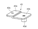
- FIG. 11 is a perspective view showing a heating coil unit support member in the induction cooking device of the second embodiment.
- FIG. 12 is a side sectional view showing a main body which is the induction heating cooker according to the second embodiment. In FIG. 8, an arrow F indicates the front side (user side).
- the basic configuration of the second embodiment is the same as that of the above-described first embodiment. explain.
- parts having the same functions and configurations as those of the first embodiment are denoted by the same reference numerals.
- the cooling configuration including the fan can be configured in the same manner as in the first embodiment, and is not shown.
- a main body 39 that is an induction heating cooker according to the second embodiment has a substantially rectangular bottom surface 40a (see FIG. 9), and a substantially rectangular opening 40i ( And a top plate 41 provided on the outer shell 40.
- the outer shell 40 has a first vertical wall 40b which is a first vertical portion having a vertical surface and is bent upward (vertical direction) at an outer edge portion of a substantially rectangular bottom surface 40a. Yes.
- the outer shell 40 is bent so as to expand outward at the upper edge of the first vertical wall 40b, thereby forming a first flat surface portion 40c that is a first horizontal portion having a horizontal surface.
- the outer shell 40 is bent upward (in the vertical direction) at the outer edge portion of the first flat surface portion 40c to form a second vertical wall 40d which is a second vertical portion having a vertical surface.
- the second vertical wall 40d is bent at the upper edge portion of the second vertical wall 40d so as to expand outward, thereby forming a second plane portion 40e which is a second horizontal portion having a horizontal plane.
- the first vertical wall 40b, the first flat surface portion 40c, the second vertical wall 40d, and the second flat surface portion 40e constitute the side surface of the outer shell 40.
- the second vertical wall 40d of the outer shell 40 is formed with a recess 40f that can accommodate the head of the screw 45c (see FIG. 12).
- a screw hole 40j through which the screw 45c passes is provided in a flat portion (vertical portion) at the bottom of the recess 40f.
- the screw hole 40j shown in FIG. 12 is hidden and cannot be seen, but has the same shape as the screw hole 21j shown in FIG.
- a burring hole 40h for screwing the heating coil unit 25 and the like is provided in the horizontal portion of the first flat portion 40c in the outer shell 40.
- the upper portion of the outer shell 40 has a substantially rectangular opening 40 i, and the first heating with the same configuration as the heating unit 25 in the first embodiment described above is provided inside the outer shell 40.
- members such as the second heating coil unit 42 and the circuit board 44 are accommodated.
- Circuit components such as a drive control circuit (including a power supply circuit) for generating a high-frequency current in the first heating coil unit 25 and the second heating coil unit 42 are mounted on the circuit board 44.
- the first heating coil unit 25 has the same configuration as that of the heating unit 25 shown in FIG. 5 described above, and the shape of the second heating coil unit 42 is more than the shape of the first heating coil unit 25. It is getting smaller. This is because the diameter of the second heating coil 42a constituting the second heating coil unit 42 is smaller than the diameter of the heating coil 29 constituting the heating coil unit 25, and the output power is small.
- the first heating coil unit 25 is formed by tightening a screw 45 a penetrating the coil attachment portion 33 b into a burring hole 40 h provided in the first flat portion 40 c of the outer shell 40. It is fixed to the flat surface portion 40c.
- the second heating coil unit 42 attaches a coil attachment plate 43 that is a heating coil unit support member to the first flat portion 40 c of the outer shell 40, and the coil attachment plate 43 is interposed therebetween. And is supported by the first flat surface portion 40c.
- the coil attachment plate 43 is a member that supports the second heating coil unit 42 and is also referred to as a heating coil unit support member.
- the circuit board 44 is configured to be fixed to the bottom surface 40a of the outer shell 40 by tightening the screws 45b.
- the coil attachment plate 43 (heating coil unit support member) includes an attachment portion 43 a whose lower surface is in contact with the first flat portion 40 c of the outer shell 40, and the second heating coil unit 42. And a coil support portion 43b on which a second coil attachment portion 42b which is a coil attachment portion is placed.
- the attachment portion 43a and the coil support portion 43b are formed with a step in the vertical direction (vertical direction).
- a screw hole 42c is formed in the second coil attachment portion 42b of the second heating coil unit 42, and a cylindrical screw fastening portion 43d protruding downward is formed in the coil support portion 43b of the coil attachment plate 43. Is provided.
- the lower surface of the attachment portion 43a of the coil attachment plate 43 and the upper surface of the coil support portion 43b are configured to have the same height in the vertical direction when attached to the first flat portion 40c of the outer shell 40. .
- the mounting portion 43a of the coil mounting plate 43 is placed on the first flat surface portion 40c, and the screw 45e penetrating the screw hole 43c is tightened to the burring hole 40h provided in the first flat surface portion 40c.
- the mounting plate 43 is fixed to the outer shell 40.
- the second coil attachment portion 42b of the second heating coil unit 42 is placed on the coil support portion 43b, and the screw 45d penetrating the screw hole 42c of the second coil attachment portion 42b becomes the screw fastening portion 43d.
- the second heating coil unit 42 is fixed to the coil attachment plate 43 by being tightened. As a result, the second heating coil unit 42 is fixed to the first flat portion 40 c of the outer shell 40 via the coil attachment plate 43.
- the lower surface of the attachment portion 43a of the coil attachment plate 43, which is a heating coil unit support member, and the upper surface of the coil support portion 43b have the same height in the vertical direction. For this reason, in the state which attached the coil attachment board 43 to the 1st plane part 40c, the 1st plane part 40c of the outer shell 40 and the upper surface of the coil support part 43b are the same height.
- the upper surfaces of the first flat surface portion 40c and the coil support portion 43b are not necessarily configured to have the same height, and can be appropriately changed.
- the shape of the coil attachment plate 43 that is, by appropriately setting the height of the lower surface of the attachment portion 43a and the upper surface of the coil support portion 43b, the second heating coil unit 42 and the top plate 41 are set. It is possible to adjust the distance between the two to a necessary distance.
- the first heating coil unit 25 and the second heating coil unit 42 are different in shape, but the second heating coil unit 42 is connected via the coil mounting plate 43. It is possible to securely mount the first flat portion 40c.
- the second embodiment includes the coil attachment plate 43 that is a heating coil unit support member that supports the second heating coil unit 42. Therefore, the heating coil unit support member is supported by the first flat surface portion 40c of the outer shell 40, and the second heating coil unit 42 is supported by the first flat surface portion 40c via the heating coil unit support member. Become. In this way, the heating coil unit having a shape that cannot be attached to the first flat portion as it is is surely secured in the first flat portion 40c, which is a horizontal portion, via the heating coil unit support member (coil mounting plate 43). And can be attached to a desired position.
- the configuration in which a plurality of heating coil units having different shapes are mounted by attaching the coil attachment plate 43 to the first flat surface portion 40c provided on the side surface of the outer shell 40 has been described.
- the present disclosure is not limited to such a configuration.
- the structure assembled using (43) is also possible. Therefore, by using the configuration of the second embodiment, in the induction heating cooker having the same shape outline (40), a plurality of models having various heating coil units (25, 42) having different shapes are configured. This makes it possible to share the outer shell.
- the heating coil unit support member (coil mounting plate 43) can be made small and inexpensive. Therefore, by creating heating coil unit support members having different shapes, it is possible to mount heating coil units having different shapes on the same outline. For this reason, according to the structure of Embodiment 2, the design freedom of a heating coil unit becomes high, and various products can be provided at low cost.
- the configuration in which the two heating coil units are arranged in the front-rear direction has been described.
- the present disclosure is not limited to the configuration in which the two heating coil units are arranged in the front-rear direction.
- two or more may be arranged in the left-right direction, and three or more may be arranged in the front-rear direction as well.
- a product in which three or more heating coil units are arranged in terms of usability when arranged in the front-rear direction is not convenient, but when a heating coil unit is arranged in the horizontal direction, Even if the number of heating coil units is three or more, the convenience is not inferior, and an easy-to-use product can be provided with an easy-to-assemble configuration.
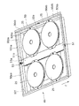
- FIG. 13 is the perspective view which looked at the state which removed the top plate unit in the induction heating cooking appliance which concerns on Embodiment 3 of this indication from the top.
- FIG. 14 is a side sectional view showing the induction heating cooker according to the third embodiment.
- the basic configuration of the third embodiment is the same as that of the above-described first embodiment. explain.
- parts having the same functions and configurations as those of the first embodiment are denoted by the same reference numerals.
- the cooling configuration including the fan is the same as the configuration of the first embodiment, and hence illustration is omitted.
- an arrow F indicates the front (user side).
- a main body 49 that is an induction heating cooker according to the third embodiment has a box shape having a substantially rectangular bottom surface 50 a and a substantially rectangular opening 50 f formed on the upper surface.
- the outer shell 50 and the top plate 52 provided on the outer shell 50 are provided.
- the outer shell 50 is bent upward (vertical direction) at the outer edge portion of the substantially rectangular bottom surface 50a, and has a first vertical wall 50ba, which is a first vertical portion having a vertical surface and extending in the left-right direction, and in the front-rear direction.
- a first vertical wall 50bb which is a first vertical portion extending is formed.
- the first flat portion 50ca and the first flat portion 50cb, which are first horizontal portions having a horizontal plane, are bent so as to spread outward at the upper edge portions of the first vertical wall 50ba and the first vertical wall 50bb. Are formed respectively.
- the first flat surface portion 50ca is provided on the front and rear side surfaces of the outer shell 50, and is formed to be elongated in the left-right direction of the opening 50f, that is, in the longitudinal direction.
- the first flat surface portion 50cb is provided on the left and right side surfaces of the outer shell 50, and is formed to be elongated in the front-rear direction of the opening 50f, that is, in the lateral direction.
- the outer shell 50 is a second vertical portion that is bent upward (in the vertical direction) at each outer edge portion of the first flat surface portion 50ca and the first flat surface portion 50cb and has a vertical surface.
- a vertical wall 50da and a second vertical wall 50db are formed.
- the second flat wall 50ea which is a second horizontal portion having a horizontal surface, is bent so as to expand outward and the second vertical wall 50db.
- a flat portion 50eb is formed.
- the joint portion 51 is suspended and screwed to the first flat surface portion 50ca provided on the front and back sides of the outer shell 50 so as to straddle the front and rear direction.
- a plurality of heating coil units 25 are supported by the first flat portion 50 cb provided on the joint portion 51 and the left and right side surfaces of the outer shell 50. ing.
- the joint portion 51 is made of a plate material having a thickness that does not deform downward due to its load even when a plurality of heating coil units 25 are placed, and the outer peripheral portion of the plate material is bent downward to have a substantially U-shaped cross section.
- a member that is not easily deformed is used by increasing the strength against bending, such as forming a letter shape.
- the joint portion 51 includes an attachment portion 51a that is a portion placed on the first flat surface portion 50ca, and a coil support portion 51b that is a portion that supports the heating coil unit 25.
- the joint portion 51 has a first flat surface by tightening a screw 53 penetrating a screw hole (not shown) provided in the attachment portion 51a into a burring hole (not shown) provided in the first flat portion 50ca. It is fixed to the part 50ca. Further, a step is provided between the attachment portion 51a and the coil support portion 51b, and the height in the vertical direction of this step is set to be the same as the thickness of the attachment portion 51a. In this way, the upper surface of the coil support portion 51b is lowered by one step with respect to the upper surface of the attachment portion 51a so that the lower surface of the attachment portion 51a and the upper surface of the coil support portion 51b have the same height.
- the induction heating cooker according to the third embodiment spans the two first flat portions 50ca that are parallel and face each other in the outer shell 50, and is a joint on which both end portions (mounting portions 51a) are placed and fixed. A portion 51 is provided.
- the heating coil unit 25 is configured to be reliably supported horizontally by the first flat surface portion 50ca via the joint portion 51.
- the induction heating cooker according to the third embodiment in the outer shell 50, not only the first flat surface portions 50cb parallel to each other on both the left and right sides but also the first flat surface portions 50ca orthogonal to them are used for a plurality of heating. It becomes the structure which can support the coil unit 25 reliably.
- a plurality of joint portions may be provided, and the heating coil unit 25 may be placed on the plurality of joint portions.
- the bottom surface 50a of the outer shell 50 becomes large.
- the bottom surface 50a formed of a thin metal plate for example, 0.5 mm
- the first flat portion 50ca on the side surface of the outer shell 50 is It is formed between the first vertical wall 50ba and the second vertical wall 50da, which are vertical portions that are difficult to deform, and is held by the first vertical wall 50ba and the second vertical wall 50da.
- the horizontal portion of the first flat surface portion 50ca on the side surface of the outer shell 50 has a structure that is difficult to move in the vertical direction.
- the joint portion 51 has a shape that has a strength that does not deform downward due to the weight of the heating coil unit 25, for example, by bending the edge portion downward and making the cross-section substantially U-shaped. The strength of the portion 51 can be easily increased.
- the heating coil unit 25 is supported by the first flat surface portion 50ca, the first flat surface portion 50cb, and the joint portion 51 that are not easily deformed downward. Since it is a structure, the distance between the heating coil unit 25 and the top plate 52 can be stabilized. Further, in the induction heating cooker of the third embodiment, the plurality of heating coil units 25 are horizontally mounted by attaching the plurality of heating coil units 25 to the first flat surface portion 50 cb and the joint portion 51 on both the left and right sides of the outer shell 50. In addition, the structure is securely held at the same height. Therefore, the distance between the top plate 52 placed on the outer shell 50 and each heating coil unit 25 can be kept constant, and the target induction heating performance of each heating coil unit 25 can be secured stably. can do.
- FIG. 15 is a side cross-sectional view illustrating an induction heating cooker according to Embodiment 4 of the present disclosure.
- the basic configuration of the fourth embodiment is the same as the configuration of the second embodiment described above, so the description of the same points will be omitted and different points will be mainly described. explain.
- parts having the same functions and configurations as those of the first and second embodiments are denoted by the same reference numerals.
- the coil attachment plate 60 in which the second heating coil unit 42 having a small heating coil is attached to the outer shell 40 includes the lower surface of the attachment portion 60a and the coil support.
- the upper surface of the part 60b is configured to have the same height. For this reason, in a state where the coil mounting plate 60 is attached to the first flat surface portion 40c on the side surface of the outer shell 40, the horizontal portion of the first flat surface portion 40c and the upper surface of the coil support portion 60b of the coil mounting plate 60 are the same. It is height.
- a screw hole 60c is provided in the attachment portion 60a of the coil attachment plate 60, and a screw tightening portion 60d is provided in the coil support portion 60b.
- the reinforcing wall 60e is formed on the coil attachment plate 60 in the induction heating cooker of the fourth embodiment so as to protrude downward (vertical direction).
- the reinforcing vertical wall 60e is disposed in contact with the inner surface of the first vertical wall 40b formed by the vertical portion of the outer shell 40.
- the mounting portion 60a is placed on the first flat surface portion 40c, and the screw 45e penetrating the screw hole 60c is tightened into the burring hole 40h provided in the first flat surface portion 40c. It is being fixed to the 1st plane part 40c.
- the second coil attachment portion 42b is placed on the coil support portion 60b of the coil attachment plate 60, and passes through the screw hole 42c provided in the second coil attachment portion 42b.
- the screw 45d to be fixed is fixed to the coil mounting plate 60 by being fastened to a screw fastening portion 60d provided in the coil support portion 60b.
- the coil support portion 60b of the coil mounting plate 60 receives the pressing force due to the weight of the second heating coil unit 42. .
- the coil attachment plate 60 since the coil attachment plate 60 is fixed to the first flat surface portion 40c provided on the side surface of the outer shell 40, the coil attachment plate 60 uses the surface in contact with the first flat surface portion 40c as a support surface. A pressing force is applied downward.
- the reinforcing vertical wall 60e provided on the coil mounting plate 60 is in contact with the vertical portion of the first vertical wall 40b, the coil mounting plate 60 bends downward in the coil support portion 60b ( Movement).
- the second heating coil unit 42 is prevented from moving downward, and the distance between the top plate 41 and the second heating coil unit 42 can be prevented from changing.
- the coil attachment plate 60 that is the heating coil unit support member is in contact with the inner surface of the first vertical wall 40b provided in the vertical portion of the outer shell 40 and protrudes downward. It is the structure which has the vertical wall 60e for reinforcement formed in this way. For this reason, the coil attachment plate 60 that is the heating coil unit support member has a high strength, and the coil support portion 60b of the coil attachment plate 60 is difficult to bend downward.
- the rigidity can be increased by bending the outer peripheral portion of the shield plate 33 or providing a bead on the bottom surface of the shield plate 33.
- the shield plate 33 a non-magnetic metal such as aluminum having a thickness of, for example, 1.5 mm is used in order to increase rigidity.
- the first flat surface portion 40c to which the coil mounting portion 33b of the shield plate 33 is attached is formed between the first vertical wall 40b and the second vertical wall 40d, which are vertical portions constituting the side surface of the outer shell 40.
- the first vertical wall 40b and the second vertical wall 40d have a structure that is not easily deformed by compression and pressing in the vertical direction.
- the second heating coil unit 42 is weighted.
- the coil attachment plate 60 is added, the coil attachment plate 60 is easily deformed (rotated) downward.
- the coil attachment plate 60 is provided with the reinforcing vertical wall 60e, the coil attachment plate 60 is rotated. It is configured to prevent movement. As a result, even if the second heating coil unit 42 is attached to the outer shell 40 using the coil attachment plate 60, the movement of the second heating coil unit 42 can be prevented.
- FIG. 16 is a perspective view showing a heating coil unit in an induction heating cooker according to Embodiment 5 of the present disclosure
- FIG. 17 is an exploded perspective view of the heating coil unit in the induction heating cooker according to Embodiment 5.
- FIG. 18 is a perspective view showing an assembled state of the outline in the induction heating cooker according to the fifth embodiment.
- the basic configuration of the fifth embodiment is the same as the configuration of the first embodiment described above, so the description of the same points will be omitted, and different points will be mainly described. explain.
- parts having the same functions and configurations as those of the first embodiment are denoted by the same reference numerals.
- the induction heating cooker according to the fifth embodiment will explain a specific configuration example of the heating coil unit and the outer shell according to the first to fourth embodiments.
- the heating coil unit 75 in the fifth embodiment shown in FIGS. 16 and 17 corresponds to the heating coil unit 25 described with reference to FIG. 5 in the first embodiment.
- the heating coil unit 75 shown in FIG. 16 is a unit in which each component is bonded to each other with an adhesive or the like, stacked and fixed on the shield plate 73, and integrated.
- the heating coil unit 75 has an electrical insulation provided on the heating coil 69, a heat shield 70 placed on the heating coil 69 and blocking heat from the cooking container, and a lower surface side of the heating coil 69.
- Insulating plate 71, ferrite 72 provided under insulating plate 71 and molded into a plurality of rods with high magnetic permeability and high magnetic permeability, and a shield plate on which ferrite 72 is placed and attached to outer shell 80 (see FIG. 18) 73 is provided.
- the heating coil 69 in the fifth embodiment will be described as an example in which the outer peripheral shape is substantially circular.
- the shield plate 73 according to the fifth embodiment has an edge portion whose outer peripheral portion rises so as to surround the plurality of radially arranged ferrites 72. Further, in the shield plate 73 in the fifth embodiment, the coil attachment portion 73b is provided inside the outer peripheral edge portion, and the first flat portion which is the first horizontal portion of the outer shell 80 is provided on the coil attachment portion 73b. A screw hole 73c for attaching 80c (see FIG. 18) is formed.
- the coil attachment portion 73b is provided inside the outer peripheral edge of the shield plate 73, the outer shape can be reduced, and the heating coil units having different shapes can be used as the shield plate. It is possible to use the same outline shape by changing the shape of the.
- the shield plate 73 according to the fifth embodiment has high rigidity because the outer peripheral portion has the raised edge. As a result, the shield plate 73 is prevented from being bent while the heating coil unit 75 is attached to the outer shell 80. As a result, in the induction heating cooker of the fifth embodiment, the distance between the top plate and the heating coil unit 75 can always be kept constant.
- FIG. 18 is a perspective view showing an assembled state of the outer shell 80 according to the fifth embodiment, and shows an enlarged side surface of the outer shell 80 bent at a right angle.
- the outer shell 80 in the fifth embodiment has the same configuration as the outer shell 21 described in the first embodiment, includes a substantially rectangular bottom surface 80a, and a first vertical wall 80b that is a first vertical portion, It has the side surface comprised by the 1st plane part 80c which is a 1st horizontal part, the 2nd vertical wall 80d which is a 2nd vertical part, and the 2nd plane part 80e which is a 2nd horizontal part. Further, a recess 81f and a screw hole 81j for attaching to the frame of the top plate unit are shown on the side surface of the outer shell 80 shown in FIG.
- the side surface portion of the outer shell 80 bent at a substantially right angle is spot welded at the welded portions 81 b and 82 b of the joint portions 81 and 82, and the strength of the side surface portion of the outer shell 80 is increased. Is more strongly secured.
- One end of the first vertical wall 80b in the longitudinal direction is provided with a joint 81 for bending and joining to the adjacent first vertical wall at a substantially right angle.
- a joining portion 82 for bending and joining to the adjacent second vertical wall at a substantially right angle is provided at one end portion in the longitudinal direction of the second vertical wall 80d.
- Positioning holes 81a and 82a for positioning are provided in the joint portions 81 and 82, respectively.
- the outer shell 80 is assembled by inserting positioning pins into through holes (not shown) provided at corresponding positions on the vertical walls facing the positioning holes 81a and 82a, and spot welding at the welds 81b and 82b. ing.
- the fifth embodiment has a configuration in which the outer shell 80 having a strong predetermined shape can be easily assembled.
- FIG. 19 is a side cross-sectional view illustrating a state in which a main body, which is an induction heating cooker according to Embodiment 6 of the present disclosure, is incorporated in a kitchen.
- FIG. 20 is a plan view showing the main body with the top plate removed in the induction heating cooker of the sixth embodiment.
- a top on which an object to be heated such as a pan is placed so as to cover the upper opening of the outer shell 21 above the outer shell 21 of the main body 20 that is the induction heating cooker according to the sixth embodiment.
- a plate 22 is arranged.
- the top plate 22 is made of a material that is not heated by electromagnetic induction, such as highly heat-resistant crystallized glass.
- a frame 93 is attached to the outer periphery of the top plate 22 to protect the end face of the top plate 22 and improve the appearance quality.
- the outer shell 21 is configured with a first stepped portion 94a for placing the top plate 22 and a second stepped portion 94b for holding an end portion of a heating coil supporting member 91 described later on the side wall 94. ing.
- a heating coil 29 and a circuit board 26 are disposed below the top plate 22 and inside the outer shell 21.
- the high frequency power is supplied from the circuit board 26 to the heating coil 29, the cooked utensils that are heated objects are directly heated. Since the principle of induction heating is well known, the description is omitted.
- heat-generating components such as a power supply circuit on the circuit board 26 are cooled by cooling air sent by a cooling mechanism including a fan 96 provided inside the outer shell 21.
- a ferrite 32 for controlling the magnetic flux generated by the heating coil 29 to have an optimum distribution for heating the cooker to be heated is disposed below the heating coil 29, a ferrite 32 for controlling the magnetic flux generated by the heating coil 29 to have an optimum distribution for heating the cooker to be heated is disposed below the heating coil 29 .
- An insulating plate 31 made of an insulating material such as mica is provided between the heating coil 29 and the ferrite 32 in order to maintain insulation between them.
- a shield plate 33 made of a non-magnetic metal such as aluminum is provided under the ferrite 32 in order to prevent erroneous heating of a magnetic metal member adjacent to the heating coil 29 and to shield noise generated from the heating coil 29. Is provided.
- the heating coil unit 25 is constituted by the heating coil 29, the insulating plate 31, the ferrite 32, the shield plate 33, and the like.
- the configuration of the heating coil unit 25 may not be the same as that of the sixth embodiment, but may be another configuration as long as the above-described effects can be obtained, and is not limited thereto.
- the heating coil unit 25 including the heating coil 29 is placed on a substantially flat heating coil support member 91 and supported from below.
- the end portion 92 of the heating coil support member 91 is held in a state of being passed to the second stepped portions 94b of the left and right side walls 94 in the outer shell 21 having a substantially box shape in which almost the upper surface is open. Further, the end 92 of the heating coil support member 91 is fastened to the second stepped portion 94 b in the outer shell 21 with a screw 95.
- the rigidity of the heating coil support member 91 is improved by bending the edge upward and laterally.
- the heating coil unit 25 including the heating coil 29 is placed on and supported by a substantially flat heating coil support member 91. Then, the vicinity of the end 92 of the heating coil support member 91 is held across the side wall 94 that is difficult to be deformed by the load in the vertical direction in the outer shell 21 of the main body 20. Since the heating coil unit 25 is thus held by the outer shell 21, deformation of the outer shell 21 due to the weight of the heating coil unit 25 and the like can be greatly reduced. Further, since the position of the heating coil 29 is stabilized by the configuration, a spring for supporting the heating coil unit 25 and a position regulating member for regulating the position against the urging force of the spring are not necessary, and the number of parts is greatly increased. Can be reduced.
- the simplification of the structure can be achieved. Moreover, since the load by heavy objects, such as the circuit board 26, is not applied to the heating coil support member 91, a bending is suppressed. Since the heating coil support member 91 only needs to support the heating col unit and its weight is small, the two heating coil units 25 are placed on one heating coil support member 91 in the present embodiment.
- the vertical gap (vertical direction) between the bottom surface 21a of the outer shell 21 and the heating coil support member 91 is set to be larger than the maximum height of the circuit board 26 having a power circuit and the like.
- a circuit board 26 is arranged in the space. The circuit board 26 is fixed by fastening screws 99 to the bosses 98 of the board holder 97 placed on the bottom surface 21 a of the outer shell 21.
- the member for supporting the heating coil unit 25 and the mounting structure thereof are not required on the bottom surface 21a of the outer shell 21, so that the wiring between the circuit board 26 and the heating coil unit 25 is not necessary. There is no waste in routing. As a result, the outer shape of the circuit board 26 can be made smaller.
- the configuration of the sixth embodiment a plurality of circuit boards including the board of the power supply circuit can be arranged side by side in a substantially horizontal direction, and the main body 20 can be thinned. Furthermore, in the configuration of the sixth embodiment, it is easy to integrate a plurality of circuit boards and construct a single circuit board, and wiring that connects the circuit boards becomes unnecessary. For this reason, in the induction heating cooker according to the sixth embodiment, it is possible to improve the reliability by reducing the number of assembling steps and parts costs and reducing the number of wiring connection points.
- the side wall 94 of the outer shell 21 is preliminarily moved so that the position of the heating coil support member 91 in the front-rear direction can be moved by a predetermined distance.
- Mounting holes 86 are provided.
- the heating coil support member 91 is provided with a spare mounting hole 86 so that the heating coil support member 91 can be fixed to the side wall 94 of the outer shell 21 with a screw 95 in a state where the position in the front-rear direction is moved by a predetermined distance.
- the auxiliary attachment hole 86 is provided in the side wall 94 of the outer shell 21, the heating coil unit 25 placed on the heating coil support member 91 can be moved in the front-rear direction by the same distance.
- FIG. 21 is a plan view showing the main body with the top plate removed in another configuration of the induction heating cooker of the present disclosure.
- the heating coil 29 can be disposed at an appropriate position simply by changing the mounting position of the heating coil support member 91, and product variations can be easily developed. .
- the heating coil support member 91 is supported only by the side wall 94 of the outer shell 21 in the sixth embodiment, the heating coil support member 91 may be supplementarily supported at a place other than the above place. . That is, since it is mainly supported by the side wall 94, the support at other locations has a high degree of freedom in selecting the location, and thus the same effect is achieved.
- the display / operation unit may be provided on either the top side or the front side of the product, and is not limited in the present disclosure, so the description is omitted.
- Embodiment 6 although it is a form which only heats the non-heating cooking utensil mounted on the top plate 22, the grill room which accommodates a cooking item in the inside and performs heating cooking is additionally provided. It may be a thing.
- FIG. 22 is a side cross-sectional view illustrating a configuration of an induction heating cooker according to the seventh embodiment of the present disclosure.
- the basic configuration of the above-described seventh embodiment is the same as that of the above-described sixth embodiment.
- the explanation is centered.
- parts having the same functions and configurations as those of the sixth embodiment are denoted by the same reference numerals.
- the heating coil support member 91 is made of a nonmagnetic metal such as aluminum.
- the heating coil support member 91 can also serve as the shield plate in the above-described sixth embodiment. It becomes composition. For this reason, in the induction heating cooking appliance of Embodiment 7, a shield board becomes unnecessary and it becomes possible to make the space below the heating coil unit 25 small, and the number of parts can be reduced. As a result, the height of the outer shell 21 can be reduced, and the product can be reduced in thickness, weight, and cost.
- Embodiments 1 to 7 can be implemented in appropriate combination.
- the example which used the screw stop as a fastening means in each embodiment was demonstrated, it is also possible to comprise using various fastening means, such as welding, fitting, and an adhesive agent.
- the induction heating cooker of the present disclosure can improve the assembly by simplifying the mounting configuration of the heating coil unit in an apparatus using one or more heating coil units. It can be applied not only to stationary or built-in induction heating cookers used in kitchens, etc., but also to all types of heating cookers having other heating coil units.
- Top plate unit 20 39, 49 Main body 21, 40, 50, 80 Outline 21a, 40a, 50a, 80a Bottom surface 21b, 40b, 50ba, 50bb, 80b First vertical wall (first vertical portion) 21c, 40c, 50ca, 50cb, 80c First plane portion (first horizontal portion) 21d, 40d, 50da, 50db, 80d Second vertical wall (second vertical portion) 21e, 40e, 50ea, 50eb, 80e Second plane part (second horizontal part) 22, 41 Top plate 25, 75 Heating coil unit (first heating coil unit) 26, 44 Circuit board 29, 69 Heating coil 30, 70 Heat shield plate 31, 71 Insulating plate 32, 72 Ferrite 33, 73 Shield plate (heating coil support member) 33a Coil receiving portion 33b Coil attachment portion 33c Screw hole 42 Second heating coil unit 43, 60 Coil attachment plate (heating coil unit support member) 51 Joint 60e Vertical wall for reinforcement
Landscapes
- Physics & Mathematics (AREA)
- Electromagnetism (AREA)
- Induction Heating Cooking Devices (AREA)
Abstract
Description
被加熱物を載置するトッププレートと、
上方に略四角形の開口部を有し、底面と側面により箱形状に形成され、上部に前記トッププレートが設けられる外郭と、
前記外郭の内部に設けられ、前記被加熱物を誘導加熱する加熱コイルおよび前記加熱コイルを支持する加熱コイル支持部材を有する加熱コイルユニットと、を備え、
前記外郭の少なくとも一組の対向する側面は、前記底面の外縁部で上方に折り曲げられて形成される第一の鉛直部と、
前記第一の鉛直部の上縁部で外側に折り曲げられて形成される第一の水平部と、
前記第一の水平部の外縁部で上方に折り曲げられ上縁部により前記開口部を形成する第二の鉛直部と、を有して構成され、
前記加熱コイルユニットは、前記第一の水平部により支持されるよう構成されている。
被加熱物を載置するトッププレートと、
上方に略四角形の開口部を有し、底面と側面により箱形状に形成され、上部に前記トッププレートが設けられる外郭と、
前記外郭の内部に設けられ、前記被加熱物を誘導加熱する加熱コイルおよび前記加熱コイルを支持する加熱コイル支持部材を有する加熱コイルユニットと、を備え、
前記外郭の少なくとも一組の対向する側面は、前記底面の外縁部で上方に折り曲げられて形成される第一の鉛直部と、
前記第一の鉛直部の上縁部で外側に折り曲げられて形成される第一の水平部と、
前記第一の水平部の外縁部で上方に折り曲げられ上縁部により前記開口部を形成する第二の鉛直部と、を有して構成され、
前記加熱コイルユニットは、前記第一の水平部により支持されるよう構成されている。
図1は、本開示の実施の形態1に係る誘導加熱調理器である本体を示す斜視図である。図2は、実施の形態1の誘導加熱調理器におけるトッププレートユニットを裏から見た斜視図である。図3は、実施の形態1の誘導加熱調理器において、トッププレートユニットを取り外した状態の本体を下から見た斜視図である。図4は、実施の形態1の誘導加熱調理器において、トッププレートユニットを取り外した状態の本体を上から見た斜視図である。
次に、本開示の実施の形態2に係る誘導加熱調理器について添付の図8~12を参照して説明する。図8は本開示の実施の形態2に係る誘導加熱調理器である本体を示す上から見た斜視図である。図9は実施の形態2の誘導加熱調理器である本体を下から見た斜視図である。図10は実施の形態2の誘導加熱調理器のトッププレートユニットを外した状態の本体を上から見た斜視図である。図11は実施の形態2の誘導加熱調理器における加熱コイルユニット支持部材を示す斜視図である。図12は実施の形態2の誘導加熱調理器である本体を示す側面断面図である。なお、図8において、矢印Fは前方(使用者側)を示す。
次に、本開示の実施の形態3に係る誘導加熱調理器について添付の図13および図14を参照して説明する。図13は、本開示の実施の形態3に係る誘導加熱調理器において、トッププレートユニットを取り外した状態を上から見た斜視図である。図14は、実施の形態3の誘導加熱調理器を示す側面断面図である。
次に、本開示の実施の形態4に係る誘導加熱調理器について添付の図15を参照して説明する。図15は本開示の実施の形態4に係る誘導加熱調理器を示す側面断面図である。
次に、本開示の実施の形態5に係る誘導加熱調理器について添付の図16~図18を参照して説明する。図16は本開示の実施の形態5に係る誘導加熱調理器における加熱コイルユニットを示す斜視図であり、図17は実施の形態5の誘導加熱調理器における加熱コイルユニットの分解斜視図である。図18は実施の形態5の誘導加熱調理器における外郭の組み立て状態を示す斜視図である。
次に、本開示の実施の形態6に係る誘導加熱調理器について添付の図19および図20を参照して説明する。図19は本開示の実施の形態6に係る誘導加熱調理器である本体がキッチンに組み込まれた状態を示す側面断面図である。図20は実施の形態6の誘導加熱調理器においてトッププレートを取り外した状態の本体を示す平面図である。
次に、本開示の実施の形態7に係る誘導加熱調理器について添付の図22を参照して説明する。図22は本開示の実施の形態7に係る誘導加熱調理器の構成を示す側面断面図である。
20、39、49 本体
21、40、50、80 外郭
21a、40a、50a、80a 底面
21b、40b、50ba、50bb、80b 第一の縦壁(第一の鉛直部)
21c、40c、50ca、50cb、80c 第一の平面部(第一の水平部)
21d、40d、50da、50db、80d 第二の縦壁(第二の鉛直部)
21e、40e、50ea、50eb、80e 第二の平面部(第二の水平部)
22、41 トッププレート
25、75 加熱コイルユニット(第一の加熱コイルユニット)
26、44 回路基板
29、69 加熱コイル
30、70 遮熱板
31、71 絶縁板
32、72 フェライト
33、73 シールド板(加熱コイル支持部材)
33a コイル受け部
33b コイル取り付け部
33c ネジ孔
42 第二の加熱コイルユニット
43、60 コイル取り付け板(加熱コイルユニット支持部材)
51 継ぎ手部
60e 補強用縦壁
Claims (9)
- 被加熱物を載置するトッププレートと、
上方に略四角形の開口部を有し、底面と側面により箱形状に形成され、上部に前記トッププレートが設けられる外郭と、
前記外郭の内部に設けられ、前記被加熱物を誘導加熱する加熱コイルおよび前記加熱コイルを支持する加熱コイル支持部材を有する加熱コイルユニットと、を備え、
前記外郭の少なくとも一組の対向する側面は、前記底面の外縁部で上方に折り曲げられて形成される第一の鉛直部と、
前記第一の鉛直部の上縁部で外側に折り曲げられて形成される第一の水平部と、
前記第一の水平部の外縁部で上方に折り曲げられ上縁部により前記開口部を形成する第二の鉛直部と、を有して構成され、
前記加熱コイルユニットは、前記第一の水平部により支持されるよう構成された誘導加熱調理器。 - 前記外郭の対向する側面は、前記第二の鉛直部の上縁部で外側若しくは内側に折り曲げられて形成される第二の水平部をさらに有して構成され、前記第二の水平部の上面が前記トッププレートに接するように構成された請求項1に記載の誘導加熱調理器。
- 前記加熱コイルユニットを支持する加熱コイルユニット支持部材をさらに備え、前記加熱コイルユニット支持部材は、前記第一の水平部に固定され、前記加熱コイルユニットは前記加熱コイルユニット支持部材を介して前記第一の水平部により支持されるよう構成された請求項1または2に記載の誘導加熱調理器。
- 前記外郭において互いに平行で向かい合う二つの前記第一の水平部に両端部が載置されて固定される継ぎ手部を有し、前記加熱コイルユニットは、前記継ぎ手部を介して前記第一の水平部で支持されるよう構成された請求項1または2に記載の誘導加熱調理器。
- 前記加熱コイルユニットを支持する加熱コイルユニット支持部材をさらに備え、前記加熱コイルユニット支持部材は前記継ぎ手部により支持され、前記加熱コイルユニットは、前記加熱コイルユニット支持部材を介して前記継ぎ手部で支持されるよう構成された請求項4に記載の誘導加熱調理器。
- 前記加熱コイルユニット支持部材は、前記第一の鉛直部の内面に接し、下方に向かって突出するよう形成された補強用縦壁を設けた請求項3または5に記載の誘導加熱調理器。
- 前記外郭の対向する側面における第一の水平部に対して、前記加熱コイル支持部材の取り付け位置が前後方向若しくは左右方向に変更可能に構成された請求項1から6のいずれか一項に記載の誘導加熱調理器。
- 前記加熱コイルを駆動制御する回路基板が前記加熱コイル支持部材の下方に設けられ、前記外郭の底面により支持されるよう構成された請求項1から7のいずれか一項に記載の誘導加熱調理器。
- 前記加熱コイル支持部材が非磁性金属により構成された請求項1から8のいずれか一項に記載の誘導加熱調理器。
Priority Applications (4)
| Application Number | Priority Date | Filing Date | Title |
|---|---|---|---|
| CN201480001538.2A CN104380841B (zh) | 2013-03-28 | 2014-03-10 | 感应加热烹调器 |
| EP14775568.0A EP2981155B1 (en) | 2013-03-28 | 2014-03-10 | Induction heating cooking device |
| JP2015508017A JP6249374B2 (ja) | 2013-03-28 | 2014-03-10 | 誘導加熱調理器 |
| US14/408,224 US9730278B2 (en) | 2013-03-28 | 2014-03-10 | Induction heating cooking device |
Applications Claiming Priority (4)
| Application Number | Priority Date | Filing Date | Title |
|---|---|---|---|
| JP2013068098 | 2013-03-28 | ||
| JP2013-068098 | 2013-03-28 | ||
| JP2013-158595 | 2013-07-31 | ||
| JP2013158595 | 2013-07-31 |
Publications (1)
| Publication Number | Publication Date |
|---|---|
| WO2014156010A1 true WO2014156010A1 (ja) | 2014-10-02 |
Family
ID=51623031
Family Applications (1)
| Application Number | Title | Priority Date | Filing Date |
|---|---|---|---|
| PCT/JP2014/001342 Ceased WO2014156010A1 (ja) | 2013-03-28 | 2014-03-10 | 誘導加熱調理器 |
Country Status (5)
| Country | Link |
|---|---|
| US (1) | US9730278B2 (ja) |
| EP (1) | EP2981155B1 (ja) |
| JP (1) | JP6249374B2 (ja) |
| CN (1) | CN104380841B (ja) |
| WO (1) | WO2014156010A1 (ja) |
Cited By (14)
| Publication number | Priority date | Publication date | Assignee | Title |
|---|---|---|---|---|
| WO2015040865A1 (ja) * | 2013-09-19 | 2015-03-26 | パナソニックIpマネジメント株式会社 | 誘導加熱調理器 |
| EP3030042A1 (en) * | 2014-12-03 | 2016-06-08 | Electrolux Appliances Aktiebolag | Induction hob |
| JP2016110911A (ja) * | 2014-12-09 | 2016-06-20 | パナソニックIpマネジメント株式会社 | 加熱調理器 |
| WO2019239557A1 (ja) | 2018-06-14 | 2019-12-19 | 三菱電機株式会社 | 誘導加熱調理器 |
| US10605464B2 (en) | 2012-10-15 | 2020-03-31 | Whirlpool Corporation | Induction cooktop |
| KR20200040529A (ko) * | 2018-10-10 | 2020-04-20 | 엘지전자 주식회사 | 피가열체 구분 기능이 개선된 유도 가열 장치 |
| US10893579B2 (en) | 2017-07-18 | 2021-01-12 | Whirlpool Corporation | Method for operating an induction cooking hob and cooking hob using such method |
| US10993292B2 (en) | 2017-10-23 | 2021-04-27 | Whirlpool Corporation | System and method for tuning an induction circuit |
| US11140751B2 (en) | 2018-04-23 | 2021-10-05 | Whirlpool Corporation | System and method for controlling quasi-resonant induction heating devices |
| US11212880B2 (en) | 2012-10-15 | 2021-12-28 | Whirlpool Emea S.P.A. | Induction cooking top |
| US20220381444A1 (en) * | 2021-05-28 | 2022-12-01 | Lg Electronics Inc. | Electric range |
| US20220386495A1 (en) * | 2021-05-28 | 2022-12-01 | Lg Electronics Inc. | Electric range |
| US12302478B2 (en) | 2018-04-23 | 2025-05-13 | Whirlpool Corporation | Control circuits and methods for distributed induction heating devices |
| US12588112B2 (en) | 2018-04-23 | 2026-03-24 | Whirlpool Corporation | System and method for controlling induction heating devices with series connected switching devices |
Families Citing this family (22)
| Publication number | Priority date | Publication date | Assignee | Title |
|---|---|---|---|---|
| ES2594181B1 (es) * | 2015-06-16 | 2017-09-19 | Bsh Electrodomésticos España, S.A. | Dispositivo de campo de cocción |
| EP3139702B1 (en) * | 2015-09-02 | 2018-11-14 | Electrolux Appliances Aktiebolag | Induction coil assembly for an induction cooking hob |
| AU2015411672B2 (en) * | 2015-10-16 | 2019-02-07 | Mitsubishi Electric Corporation | Heating cooker system, inductive heating cooker, and electric apparatus |
| US20170164777A1 (en) * | 2015-12-10 | 2017-06-15 | Spectrum Brands, Inc. | Induction cooktop |
| JP6851012B2 (ja) * | 2016-09-15 | 2021-03-31 | パナソニックIpマネジメント株式会社 | 誘導加熱調理器 |
| US11665790B2 (en) * | 2016-12-22 | 2023-05-30 | Whirlpool Corporation | Induction burner element having a plurality of single piece frames |
| ES2682522B1 (es) * | 2017-03-20 | 2019-07-29 | Bsh Electrodomesticos Espana Sa | Dispositivo de aparato domestico |
| ES2684109B1 (es) * | 2017-03-30 | 2019-09-16 | Bsh Electrodomesticos Espana Sa | Dispositivo de campo de cocción |
| EP3448120B1 (en) * | 2017-08-22 | 2022-10-12 | Electrolux Appliances Aktiebolag | Cooking hob |
| DE102018209197A1 (de) * | 2018-06-08 | 2019-12-12 | Arpa Sasu | Induktionskochfeld und Verfahren zur Montage eines Induktionskochfelds |
| EP3691411A1 (de) * | 2019-01-31 | 2020-08-05 | Miele & Cie. KG | Kochfeldmodul und verfahren zur kontrolle des korrekten einbaus |
| KR20220072206A (ko) * | 2020-11-25 | 2022-06-02 | 엘지전자 주식회사 | 전기 레인지 |
| EP4044771A1 (en) * | 2021-02-16 | 2022-08-17 | Electrolux Appliances Aktiebolag | Household appliance |
| KR20220161027A (ko) * | 2021-05-28 | 2022-12-06 | 엘지전자 주식회사 | 전기 레인지 |
| KR20220160921A (ko) * | 2021-05-28 | 2022-12-06 | 엘지전자 주식회사 | 전기 레인지 |
| KR20220166583A (ko) * | 2021-06-10 | 2022-12-19 | 엘지전자 주식회사 | 전기 레인지 |
| US12464608B2 (en) * | 2021-12-06 | 2025-11-04 | Whirlpool Corporation | Combined inductor shielding system |
| WO2024076673A2 (en) * | 2022-10-05 | 2024-04-11 | W.C. Bradley Co. | Induction grill |
| EP4432781A1 (en) | 2023-03-16 | 2024-09-18 | Renta Elektrikli Ev Aletleri Sanayi Ve Dis Ticaret Limited Sirketi | Bracket assembly in induction cookers |
| TR2023019664A1 (tr) * | 2023-12-29 | 2025-07-21 | Renta Elektrikli Ev Aletleri Sanayi Ve Dis Ticaret Ltd Sirketi | Bi̇r braket |
| USD1095132S1 (en) * | 2024-05-02 | 2025-09-30 | Sef Tech Co., Ltd. | Battery powered induction cooker |
| USD1095131S1 (en) * | 2024-05-02 | 2025-09-30 | Sef Tech Co., Ltd. | Battery powered induction cooker |
Citations (5)
| Publication number | Priority date | Publication date | Assignee | Title |
|---|---|---|---|---|
| JP2002033184A (ja) | 2000-07-14 | 2002-01-31 | Matsushita Electric Ind Co Ltd | 誘導加熱調理器 |
| JP2004172138A (ja) | 2004-01-30 | 2004-06-17 | Matsushita Electric Ind Co Ltd | 誘導加熱調理器 |
| JP2009011400A (ja) * | 2007-06-30 | 2009-01-22 | Cleanup Corp | システムキッチン |
| WO2010103766A1 (ja) * | 2009-03-13 | 2010-09-16 | パナソニック株式会社 | 誘導加熱調理器及び厨房装置 |
| JP2012243602A (ja) * | 2011-05-20 | 2012-12-10 | Panasonic Corp | 誘導加熱調理器 |
Family Cites Families (5)
| Publication number | Priority date | Publication date | Assignee | Title |
|---|---|---|---|---|
| DE19854230A1 (de) | 1998-11-24 | 2000-05-25 | Bsh Bosch Siemens Hausgeraete | Kochfeld mit Positionierungselement für einen Heizkörper |
| US6410892B1 (en) * | 2001-06-19 | 2002-06-25 | Bsh Home Appliances Corporation | Cooktop having a flat glass ceramic cooking surface |
| EP1542509B1 (en) | 2002-08-07 | 2013-08-21 | Panasonic Corporation | Induction heater |
| WO2011048816A1 (ja) * | 2009-10-23 | 2011-04-28 | パナソニック株式会社 | 誘導加熱装置 |
| ES2614406T3 (es) * | 2010-09-06 | 2017-05-31 | BSH Hausgeräte GmbH | Equipo de placa de cocina |
-
2014
- 2014-03-10 CN CN201480001538.2A patent/CN104380841B/zh active Active
- 2014-03-10 EP EP14775568.0A patent/EP2981155B1/en active Active
- 2014-03-10 WO PCT/JP2014/001342 patent/WO2014156010A1/ja not_active Ceased
- 2014-03-10 US US14/408,224 patent/US9730278B2/en not_active Expired - Fee Related
- 2014-03-10 JP JP2015508017A patent/JP6249374B2/ja active Active
Patent Citations (5)
| Publication number | Priority date | Publication date | Assignee | Title |
|---|---|---|---|---|
| JP2002033184A (ja) | 2000-07-14 | 2002-01-31 | Matsushita Electric Ind Co Ltd | 誘導加熱調理器 |
| JP2004172138A (ja) | 2004-01-30 | 2004-06-17 | Matsushita Electric Ind Co Ltd | 誘導加熱調理器 |
| JP2009011400A (ja) * | 2007-06-30 | 2009-01-22 | Cleanup Corp | システムキッチン |
| WO2010103766A1 (ja) * | 2009-03-13 | 2010-09-16 | パナソニック株式会社 | 誘導加熱調理器及び厨房装置 |
| JP2012243602A (ja) * | 2011-05-20 | 2012-12-10 | Panasonic Corp | 誘導加熱調理器 |
Cited By (22)
| Publication number | Priority date | Publication date | Assignee | Title |
|---|---|---|---|---|
| US11655984B2 (en) | 2012-10-15 | 2023-05-23 | Whirlpool Corporation | Induction cooktop |
| US11212880B2 (en) | 2012-10-15 | 2021-12-28 | Whirlpool Emea S.P.A. | Induction cooking top |
| US10605464B2 (en) | 2012-10-15 | 2020-03-31 | Whirlpool Corporation | Induction cooktop |
| WO2015040865A1 (ja) * | 2013-09-19 | 2015-03-26 | パナソニックIpマネジメント株式会社 | 誘導加熱調理器 |
| US10555381B2 (en) | 2014-12-03 | 2020-02-04 | Electrolux Appliances Aktiebolag | Induction hob |
| AU2015357338B2 (en) * | 2014-12-03 | 2021-03-04 | Electrolux Appliances Aktiebolag | Induction hob |
| WO2016087297A1 (en) * | 2014-12-03 | 2016-06-09 | Electrolux Appliances Aktiebolag | Induction hob |
| EP3030042A1 (en) * | 2014-12-03 | 2016-06-08 | Electrolux Appliances Aktiebolag | Induction hob |
| JP2016110911A (ja) * | 2014-12-09 | 2016-06-20 | パナソニックIpマネジメント株式会社 | 加熱調理器 |
| US10893579B2 (en) | 2017-07-18 | 2021-01-12 | Whirlpool Corporation | Method for operating an induction cooking hob and cooking hob using such method |
| US12063731B2 (en) | 2017-10-23 | 2024-08-13 | Whirlpool Corporation | System and method for tuning an induction circuit |
| US10993292B2 (en) | 2017-10-23 | 2021-04-27 | Whirlpool Corporation | System and method for tuning an induction circuit |
| US12588112B2 (en) | 2018-04-23 | 2026-03-24 | Whirlpool Corporation | System and method for controlling induction heating devices with series connected switching devices |
| US11140751B2 (en) | 2018-04-23 | 2021-10-05 | Whirlpool Corporation | System and method for controlling quasi-resonant induction heating devices |
| US12302478B2 (en) | 2018-04-23 | 2025-05-13 | Whirlpool Corporation | Control circuits and methods for distributed induction heating devices |
| US12245348B2 (en) | 2018-04-23 | 2025-03-04 | Whirlpool Corporation | System and method for controlling quasi-resonant induction heating devices |
| US11910511B2 (en) | 2018-06-14 | 2024-02-20 | Mitsubishi Electric Corporation | Induction heating cooking apparatus |
| WO2019239557A1 (ja) | 2018-06-14 | 2019-12-19 | 三菱電機株式会社 | 誘導加熱調理器 |
| KR102631230B1 (ko) * | 2018-10-10 | 2024-01-29 | 엘지전자 주식회사 | 피가열체 구분 기능이 개선된 유도 가열 장치 |
| KR20200040529A (ko) * | 2018-10-10 | 2020-04-20 | 엘지전자 주식회사 | 피가열체 구분 기능이 개선된 유도 가열 장치 |
| US20220386495A1 (en) * | 2021-05-28 | 2022-12-01 | Lg Electronics Inc. | Electric range |
| US20220381444A1 (en) * | 2021-05-28 | 2022-12-01 | Lg Electronics Inc. | Electric range |
Also Published As
| Publication number | Publication date |
|---|---|
| US20150114953A1 (en) | 2015-04-30 |
| CN104380841A (zh) | 2015-02-25 |
| CN104380841B (zh) | 2016-08-24 |
| JP6249374B2 (ja) | 2017-12-20 |
| JPWO2014156010A1 (ja) | 2017-02-16 |
| EP2981155A1 (en) | 2016-02-03 |
| US9730278B2 (en) | 2017-08-08 |
| EP2981155B1 (en) | 2020-03-04 |
| EP2981155A4 (en) | 2016-04-13 |
Similar Documents
| Publication | Publication Date | Title |
|---|---|---|
| JP6249374B2 (ja) | 誘導加熱調理器 | |
| CN104115553B (zh) | 电磁炉炉盘 | |
| WO2010137271A1 (ja) | 誘導加熱調理器 | |
| WO2012137481A1 (ja) | 誘導加熱調理器 | |
| JP2011258442A (ja) | 誘導加熱調理器 | |
| JP5076737B2 (ja) | 誘導加熱調理器 | |
| JP2005028020A (ja) | 電磁誘導加熱調理器における胴反射板の取付け構造 | |
| JP2005308296A (ja) | 加熱調理器 | |
| JP2018061573A (ja) | 加熱調理器 | |
| KR102419666B1 (ko) | 전기 레인지 | |
| JP3405949B2 (ja) | 誘導加熱調理器 | |
| KR20050016183A (ko) | 가열 조리기 | |
| KR200183821Y1 (ko) | 전자레인지의 고압 트랜스포머 고정 구조 | |
| JP2004342346A (ja) | 誘導加熱調理器 | |
| JP5295346B2 (ja) | 誘導加熱調理器 | |
| CN222670097U (zh) | 通用电磁线盘组件 | |
| JP7103825B2 (ja) | 調理器 | |
| JP2009165595A (ja) | 誘導加熱調理器 | |
| JP5636858B2 (ja) | 誘導加熱調理器 | |
| JP2019180534A (ja) | 調理器 | |
| CN209054593U (zh) | 电磁炉 | |
| KR20220072206A (ko) | 전기 레인지 | |
| JP2023175233A (ja) | 誘導加熱調理器 | |
| JP6272414B2 (ja) | 誘導加熱調理器 | |
| JP5698309B2 (ja) | 誘導加熱調理器 |
Legal Events
| Date | Code | Title | Description |
|---|---|---|---|
| ENP | Entry into the national phase |
Ref document number: 2015508017 Country of ref document: JP Kind code of ref document: A |
|
| 121 | Ep: the epo has been informed by wipo that ep was designated in this application |
Ref document number: 14775568 Country of ref document: EP Kind code of ref document: A1 |
|
| WWE | Wipo information: entry into national phase |
Ref document number: 14408224 Country of ref document: US |
|
| WWE | Wipo information: entry into national phase |
Ref document number: 2014775568 Country of ref document: EP |
|
| NENP | Non-entry into the national phase |
Ref country code: DE |