WO2014156058A1 - シート製造装置、シート製造装置の制御方法 - Google Patents
シート製造装置、シート製造装置の制御方法 Download PDFInfo
- Publication number
- WO2014156058A1 WO2014156058A1 PCT/JP2014/001550 JP2014001550W WO2014156058A1 WO 2014156058 A1 WO2014156058 A1 WO 2014156058A1 JP 2014001550 W JP2014001550 W JP 2014001550W WO 2014156058 A1 WO2014156058 A1 WO 2014156058A1
- Authority
- WO
- WIPO (PCT)
- Prior art keywords
- unit
- temperature
- defibrating
- manufacturing apparatus
- sheet manufacturing
- Prior art date
- Legal status (The legal status is an assumption and is not a legal conclusion. Google has not performed a legal analysis and makes no representation as to the accuracy of the status listed.)
- Ceased
Links
Images


Classifications
-
- D—TEXTILES; PAPER
- D21—PAPER-MAKING; PRODUCTION OF CELLULOSE
- D21F—PAPER-MAKING MACHINES; METHODS OF PRODUCING PAPER THEREON
- D21F1/00—Wet end of machines for making continuous webs of paper
- D21F1/48—Suction apparatus
-
- D—TEXTILES; PAPER
- D04—BRAIDING; LACE-MAKING; KNITTING; TRIMMINGS; NON-WOVEN FABRICS
- D04H—MAKING TEXTILE FABRICS, e.g. FROM FIBRES OR FILAMENTARY MATERIAL; FABRICS MADE BY SUCH PROCESSES OR APPARATUS, e.g. FELTS, NON-WOVEN FABRICS; COTTON-WOOL; WADDING ; NON-WOVEN FABRICS FROM STAPLE FIBRES, FILAMENTS OR YARNS, BONDED WITH AT LEAST ONE WEB-LIKE MATERIAL DURING THEIR CONSOLIDATION
- D04H1/00—Non-woven fabrics formed wholly or mainly of staple fibres or like relatively short fibres
- D04H1/70—Non-woven fabrics formed wholly or mainly of staple fibres or like relatively short fibres characterised by the method of forming fleeces or layers, e.g. reorientation of fibres
- D04H1/72—Non-woven fabrics formed wholly or mainly of staple fibres or like relatively short fibres characterised by the method of forming fleeces or layers, e.g. reorientation of fibres the fibres being randomly arranged
- D04H1/732—Non-woven fabrics formed wholly or mainly of staple fibres or like relatively short fibres characterised by the method of forming fleeces or layers, e.g. reorientation of fibres the fibres being randomly arranged by fluid current, e.g. air-lay
-
- D—TEXTILES; PAPER
- D21—PAPER-MAKING; PRODUCTION OF CELLULOSE
- D21B—FIBROUS RAW MATERIALS OR THEIR MECHANICAL TREATMENT
- D21B1/00—Fibrous raw materials or their mechanical treatment
- D21B1/04—Fibrous raw materials or their mechanical treatment by dividing raw materials into small particles, e.g. fibres
- D21B1/06—Fibrous raw materials or their mechanical treatment by dividing raw materials into small particles, e.g. fibres by dry methods
- D21B1/063—Fibrous raw materials or their mechanical treatment by dividing raw materials into small particles, e.g. fibres by dry methods using grinding devices
-
- D—TEXTILES; PAPER
- D21—PAPER-MAKING; PRODUCTION OF CELLULOSE
- D21F—PAPER-MAKING MACHINES; METHODS OF PRODUCING PAPER THEREON
- D21F11/00—Processes for making continuous lengths of paper, or of cardboard, or of wet web for fibre board production, on paper-making machines
-
- D—TEXTILES; PAPER
- D21—PAPER-MAKING; PRODUCTION OF CELLULOSE
- D21H—PULP COMPOSITIONS; PREPARATION THEREOF NOT COVERED BY SUBCLASSES D21C OR D21D; IMPREGNATING OR COATING OF PAPER; TREATMENT OF FINISHED PAPER NOT COVERED BY CLASS B31 OR SUBCLASS D21G; PAPER NOT OTHERWISE PROVIDED FOR
- D21H11/00—Pulp or paper, comprising cellulose or lignocellulose fibres of natural origin only
- D21H11/14—Secondary fibres
Definitions
- the present invention relates to a sheet manufacturing apparatus and a control method for the sheet manufacturing apparatus.
- waste paper discharged from an office includes waste paper on which confidential matters are described, it is desired that the waste paper can be processed in its own office from the viewpoint of maintaining confidentiality. Since a wet sheet manufacturing apparatus that uses a large amount of water is not suitable for a small office, a dry sheet manufacturing apparatus with a simplified structure has been proposed (see, for example, Patent Document 1).
- the present invention has been made to solve at least a part of the problems described above, and can be realized as the following forms or application examples.
- a sheet manufacturing apparatus includes a defibrating unit that defibrates a material to be defibrated to generate a defibrated material, a temperature acquisition unit that acquires a temperature of the defibrating unit, And a control unit that changes a mass flow rate of air including the defibrated material conveyed from the defibrating unit.
- the mass flow rate of the air containing the defibrated material is changed based on the acquired temperature of the defibrating unit, the change in the mass flow rate of the air caused by the change in the temperature of the defibrating unit can be adjusted and stable. Fibrillation drive is possible. Thereby, a defibrated state is stabilized and a high quality sheet can be manufactured.
- Application Example 2 In the control unit of the sheet manufacturing apparatus according to the application example, when the acquired temperature is higher, the mass flow rate is increased than when the acquired temperature is lower. To do.
- the temperature of the defibrating unit When the temperature of the defibrating unit is higher, the density of air decreases, and the defibrated material transportability decreases. If it does so, it will become a defibration excessive state more defibrated and shortening will advance, and when a sheet
- the sheet manufacturing apparatus includes a suction unit that sucks the defibrated material, and the control unit obtains the acquired temperature more when the acquired temperature is higher. It is characterized in that the suction force of the suction part is made larger than when the pressure is low.
- the mass flow rate of air can be increased by increasing the suction force of the suction portion. Thereby, the conveyance property of a defibrated material can be improved.
- the defibrating unit includes a rotating blade that rotates, and the control unit obtains the acquired temperature more when the acquired temperature is higher.
- the rotational speed of the rotary blade is increased as compared with the case where it is low.
- the temperature acquisition unit of the sheet manufacturing apparatus according to the application example acquires a temperature inside the defibrating unit.
- the defibrating unit has an upstream conveyance path and a downstream conveyance path connected to an upstream side and a downstream side with respect to the conveyance direction of the defibrated material, and the temperature acquisition The section is characterized by acquiring temperatures inside the upstream conveyance path and inside the downstream conveyance path.
- Schematic which shows the structure of a sheet manufacturing apparatus.
- Another schematic diagram showing the configuration of a sheet manufacturing apparatus.
- Schematic which shows the structure around a defibrating part.
- the flowchart which shows the control method of a sheet manufacturing apparatus.
- the sheet manufacturing apparatus is based on a technology that recycles raw materials (defibrated material) such as used paper and pulp sheets into new sheets. Then, a defibrating unit that defibrates the defibrated material to generate a defibrated material, a temperature acquisition unit that acquires the temperature of the defibrated unit, and a mass of air that includes the defibrated material conveyed from the defibrated unit And a control unit that changes the flow rate.
- the raw material as a defibrated material supplied to the sheet manufacturing apparatus according to the present embodiment is, for example, waste paper (raw material PU) such as A4 size which is currently mainstream in offices. This will be specifically described below.
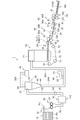
- the sheet manufacturing apparatus 1 includes a supply unit 10, a crushing unit 20, a defibrating unit 30, a classifying unit 40, a receiving unit 45, an additive charging unit 60, The molding unit 70, the moisture spray unit 120, the pressurizing unit 80, the heating and pressurizing unit 90, and the cutting unit 100 are provided. Furthermore, the temperature acquisition part 110 which acquires the temperature of the defibrating part 30, and the blower 34 which adjusts the flow mass of air are provided. And in the sheet manufacturing apparatus 1, the control part (not shown) which controls these members is provided.
- the supply unit 10 supplies the raw material PU as the material to be defibrated to the crushing unit 20.
- the supply unit 10 includes, for example, a tray 11 on which a plurality of raw material PUs are stacked and an automatic feed mechanism 12 that can continuously input the raw material PUs placed on the tray 11 into the crushing unit 20. Yes.
- the crushing unit 20 cuts the supplied raw material PU into a few centimeter square pieces.
- the crushing unit 20 includes a crushing blade 21 and constitutes an apparatus in which the cutting width of a normal shredder blade is widened. Thereby, the supplied raw material PU can be easily cut into strips. The strips are supplied to the defibrating unit 30 through the upstream conveyance path 25.
- the defibrating unit 30 includes a rotating rotary blade, and defibrates the fine pieces supplied from the crushing unit 20 into a fibrous form (cotton shape).
- the defibrating unit 30 of the present embodiment is a dry defibrating that performs defibrating in the air instead of defibrating in water.
- a disc refiner for example, a disc refiner, a turbo mill (manufactured by Turbo Industry Co., Ltd.), a selenium mirror (manufactured by Masuko Sangyo Co., Ltd.), or a dry defibrating apparatus equipped with a wind generating mechanism can be appropriately applied.
- the size of the strip put into such a dry defibrating unit 30 may be the same size as that discharged by a normal shredder.
- the printed ink, toner, coating material to the raw material such as the bleeding preventing material and the like are released from the state of adhering to the fibers (hereinafter referred to as "ink particles").
- the defibrated material discharged from the defibrating unit 30 is fibers and ink particles obtained by defibrating the strips.
- the defibrating unit 30 is a mechanism that generates an air flow by the rotation of the rotary blade, and the defibrated material moves in the defibrating unit 30.
- a downstream conveyance path 35 is provided between the defibrating unit 30 and the classification unit 40 to convey the defibrated material in an air current, and a blower 34 that controls the speed of the air current is disposed in the downstream conveyance path 35.
- the defibrated material is conveyed to the classification unit 40 at a speed suitable for classification by the blower 34.
- the blower 34 may have a function of sucking the defibrated material from the defibrating unit 30. In this case, the blower 34 becomes a suction part.
- the suction unit can control the suction force.
- the suction unit such as the blower 34, the amount of defibrated material moving in the defibrating unit 30 can be controlled, and the mass flow rate of air containing the defibrated material can be controlled.
- FIG. 3 is a schematic diagram showing a configuration around the defibrating unit.
- a first thermometer 113 around the defibrating unit 30, a first thermometer 113, a second thermometer 114, and a third thermometer 115 are installed as a temperature acquisition unit 110 that acquires temperature.
- the defibrating unit 30 is provided with a first thermometer 113 that acquires the temperature of the defibrating unit 30.
- the first thermometer 113 measures the temperature inside the defibrating unit 30.
- the upstream conveyance path 25 and the downstream conveyance path 35 connected to the upstream side and the downstream side, respectively, in the conveyance direction of the defibrated material of the defibrating unit 30 measure the temperature inside the upstream conveyance path 25.
- thermometer 114 and a third thermometer 115 that measures the temperature inside the downstream conveyance path 35 are installed. And according to the temperature acquired by these 1st thermometer 113, 2nd thermometer 114, and 3rd thermometer 115, it is comprised so that the suction amount of the blower 34 as a suction part may be controlled.
- the classifying unit 40 classifies the conveyed defibrated material into ink particles and fibers, and removes the ink particles.
- the cyclone 40 as the classifying unit 40 of the present embodiment is applied.
- the cyclone 40 is desirable because the tangential input type cyclone has a relatively simple structure.
- another type of airflow classifier may be used instead of the cyclone 40.
- an airflow classifier other than the cyclone 40 for example, an elbow jet, an eddy classifier, or the like is used.
- the airflow classifier generates a swirling airflow, which is separated and classified by the difference in centrifugal force received depending on the size and density of the defibrated material, and the classification point can be adjusted by adjusting the speed and centrifugal force of the airflow. .
- the cyclone 40 of the present embodiment is provided at an introduction port 41 introduced from the defibrating unit 30, a cylindrical portion 43 with the introduction port 41 attached in a tangential direction, a conical portion 42 following the cylindrical portion 43, and a lower portion of the conical portion.
- a lower outlet 46 and an upper exhaust port 44 for discharging fine powder provided at the upper center of the cylindrical portion 43.
- the airflow on which the defibrated material introduced from the introduction port 41 of the cyclone 40 is changed into a circumferential motion at the cylindrical portion 43 and moves to the conical portion 42. And it isolate
- the defibrated material is classified into two types of fibers and ink particles other than the fibers, the fibers are larger than the ink particles or have a higher density. Therefore, the defibrated material is separated into ink particles that are smaller than the fibers and have a lower density and fibers that are larger than the ink particles and have a higher density by classification.
- the separated ink particles are led to the upper exhaust port 44 as fine powder together with air. Then, relatively small and low density ink particles are discharged from the upper exhaust port 44 of the cyclone 40. The discharged ink particles are collected from the upper exhaust port 44 of the cyclone 40 through the pipe 203 to the receiving part 45. On the other hand, fibers larger than the ink particles and having a higher density are conveyed from the lower outlet of the cyclone 40 toward the forming unit 70 as defibrated fibers.
- an additive feeding unit 60 for adding an additive to the defibrated fiber is provided.
- the additive include a fusion resin, a flame retardant, a whiteness improver, a paper strength enhancer, and a sizing agent. Some or all of these additives may be omitted, or other additives may be added.
- the additive is stored in the storage unit 61 and is input from the input port 62 by an input mechanism (not shown).
- a sheet is formed using a mixture of defibrated fibers and additives. Therefore, a fiber obtained by mixing a defibrated fiber with a fusion resin or an additive is called a material fiber.
- the molding part 70 is for depositing material fibers in a uniform thickness.
- the forming unit 70 has a mechanism for uniformly dispersing the material fibers in the air and a mechanism for sucking the material fibers onto the mesh belt 73.
- the forming unit 71 is provided with a forming drum 71 into which the material fibers are charged. By rotating the forming drum 71, it is possible to uniformly mix the additive into the fiber.
- a small hole screen is provided on the surface of the forming drum 71. By rotating the forming drum 71 and allowing the material fibers to pass through the small hole screen, the material fibers can be uniformly dispersed in the air.
- an endless mesh belt 73 in which a mesh is formed is disposed vertically below the forming drum 71.
- the mesh belt 73 is stretched by a plurality of stretching rollers 72, and moves in one direction when at least one of the stretching rollers 72 rotates.
- a suction device 75 that generates an air flow directed downward in the vertical direction via a mesh belt 73 is provided below the forming drum 71. By the suction device 75, the material fibers dispersed in the air can be sucked onto the mesh belt 73.
- the material fibers When the material fibers are introduced into the forming drum 71 of the molding unit 70, the material fibers pass through the small hole screen on the surface of the forming drum 71 and are deposited on the mesh belt 73 by the suction force by the suction device 75. . At this time, by moving the mesh belt 73 in one direction, the material fibers can be deposited with a uniform thickness.
- the deposit containing the material fibers deposited in this way is called a web W.
- the mesh belt may be metallic, resinous, or non-woven fabric, and may be any material as long as material fibers can be deposited and an air stream can pass therethrough.
- the suction device 75 can be formed by forming a sealed box having a window of a desired size opened under the mesh belt 73, and sucking air in the box from other than the window to make the inside of the box low vacuum.
- the web W is transported in the web transport direction indicated by the arrow in FIG. 2 by moving the mesh belt 73.
- the water spray unit 120 sprays and adds water toward the web W being conveyed. Thereby, the hydrogen bond between fibers can be strengthened. Then, the web W sprayed with moisture is conveyed to the pressure unit 80.
- the pressurizing unit 80 pressurizes the conveyed web W.
- the pressure unit 80 includes two pairs of pressure rollers 81.
- the web W is compressed by allowing the web W sprayed with moisture to pass between the pressure rollers 81 facing each other. Then, the compressed web W is conveyed to the heating and pressing unit 90.
- the heating and pressurizing unit 90 simultaneously heats and pressurizes the conveyed web W.
- the heating and pressing unit 90 includes two pairs of heating rollers 91.
- the compressed web W is heated and pressurized by passing between the opposed heating rollers 91.
- the fusion resin is melted by the heating roller 91 and the fibers are bound to each other.
- an excellent sheet can be produced by improving the strength of the sheet and drying excess moisture.
- heating be performed by simultaneously applying pressure and heating to the web W by installing a heater in the heating roller 91.
- a guide 108 for guiding the web W is disposed below the pressure roller 81 and the heating roller 91.
- the sheet (web W) obtained as described above is conveyed to the cutting unit 100.
- the cutting unit 100 includes a cutter 101 that cuts in the transport direction and a cutter 102 that cuts in a direction orthogonal to the transport direction, and cuts the sheet formed in a long shape into a desired size.
- the cut sheet Pr (web W) is stacked on the stacker 160.
- FIG. 4 is a flowchart showing the control method.
- the temperature of the defibrating unit 30 is acquired.
- each temperature measured by the 1st thermometer 113, the 2nd thermometer 114, and the 3rd thermometer 115 as the temperature acquisition part 110 is acquired (step S1).
- the mass flow rate of the air containing the defibrated material conveyed from the defibrating unit 30 is controlled according to the acquired temperature.
- the control unit determines whether or not the temperature acquired in step S1 is higher than a predetermined temperature (step S2). Since the internal temperature gradually increases as the defibrating unit 30 continues to be driven, the predetermined temperature is set as the temperature when the defibrating unit 30 is driven for a long time.
- the defibrating unit 30 is normally driven. In this case, the blower 34 as the suction unit is controlled in the normal mode. Suction is performed (step S4).
- step S2 when the acquired temperature is higher than a predetermined temperature (YES in step S2), the defibrating unit 30 is being driven for a long time.
- the blower 34 is controlled in the case of step S4. Is sucked with a larger suction force to increase the mass flow rate of air (step S3).
- the suction force of the blower 34 when the acquired temperature is higher than a predetermined temperature, the suction force of the blower 34 is set larger than that in the normal mode. Thereby, the mass flow rate of air becomes large, and the conveyance property of a defibrated material can be improved. And since the defibration excessive state of the defibrating part 30 is eliminated, generation
- predetermined temperature in this embodiment, although it divided by whether it is higher than predetermined temperature, you may divide by whether it is low. Further, a plurality of predetermined temperatures may be provided and divided into three or more according to the number provided. The predetermined temperature in this case is a plurality of temperatures including the temperature when driven for a long time. Further, instead of comparison with a predetermined temperature, comparison between acquired temperatures may be performed. In any case, the mass flow rate is higher and the suction force is higher when the acquired temperature is higher than when it is lower.
- the temperature of the defibrating unit 30 is measured by the temperature acquisition unit 110. For example, when the temperature of the defibrating unit 30 is high, the suction force of the blower 34 as the suction unit is increased. Thereby, the conveyance property of the defibrated material in the defibrating unit 30 is improved, the excessive defibration is eliminated, the number of short fibers is small, and the strength is ensured.
- the first thermometer 113 measures the temperature inside the defibrating unit 30, but is not limited thereto. You may comprise so that the temperature of the outer surface of the defibrating part 30 may be measured.
- the second thermometer 114 and the third thermometer 115 may be configured to measure the temperatures of the outer surfaces of the upstream conveyance path 25 and the downstream conveyance path 35. Even if it does in this way, since the temperature change of each part can be acquired easily, the same effect as the above can be acquired.
- the first thermometer 113, the second thermometer 114, and the third thermometer 115 are provided as the temperature acquisition unit 110, but the present invention is not limited to this configuration.
- three thermometers it is possible to grasp the temperature rise of the defibrated material in the defibrating unit 30 due to the temperature difference between the upstream and downstream of the defibrating unit 30 while grasping the internal temperature of the defibrating unit 30.
- only the temperature in the defibrating unit 30 may be grasped as the first thermometer 113 alone.
- the second thermometer 114 and the third thermometer 115 may be provided, and the temperature difference between the upstream and downstream of the defibrating unit 30 may be grasped.
- thermometer 115 only the third thermometer 115 may be provided. Even when the second thermometer 114 and the third thermometer 115 are provided, or when only the third thermometer 115 is provided, the temperature of the defibrated material passing through the defibrating unit 30 is estimated. Therefore, it can be considered that the temperature of the defibrating unit 30 is acquired. Thus, the cost can be reduced by reducing the number of thermometers. Further, a thermometer may be added to the first thermometer 113, the second thermometer 114, and the third thermometer 115. In this way, the temperature of the defibrating unit 30 and the vicinity of the defibrating unit 30 can be acquired in more detail.
- the mass flow rate of air including the defibrated material conveyed from the defibrating unit 30 is changed by controlling the blower 34.
- the present invention is not limited to this configuration.
- a wind generating mechanism that generates an air flow is disposed in the defibrating unit 30.
- the defibrating unit 30 includes a rotating blade that rotates, and the control unit controls the number of rotations of the rotating blade according to the acquired temperature. For example, when the acquired temperature is higher than a predetermined temperature, the rotational speed of the rotary blade is set larger than when the acquired temperature is lower than the predetermined temperature.
- a blade that generates an airflow may be provided separately from the rotary blade, and may be rotated together with the rotary blade.
- the mass flow rate of the air containing the defibrated material conveyed from the defibrating unit 30 is changed by controlling the blower 34, but is not limited to this configuration.
- the mass flow rate of air including the defibrated material conveyed from the defibrating unit 30 may be changed by controlling the suction device 75 of the forming unit 70.
- an airflow introduction unit is provided upstream of the defibrating unit 30, and the introduction force for introducing air into the defibrating unit 30 is controlled to control the airflow. May be.
- Increasing the introduction force from the airflow introduction portion and increasing the suction force by the suction portion have the same effect.
- the temperature of the defibrating unit 30 is directly acquired by the first thermometer 113, but the present invention is not limited to this configuration.
- a flow meter 116 for measuring the air flow rate is provided in the downstream conveyance path 35, and the measured value of the flow meter 116 is used to calculate or create a data table created in advance in the defibrating unit 30.
- the temperature may be obtained. Since the mass flow rate decreases when the temperature increases, the flow rate may be measured without measuring the temperature. For this reason, the flow meter 116 can also be regarded as the temperature acquisition unit 110. Even if it does in this way, the same effect as the above can be acquired.
- the sheet according to the above-mentioned embodiment mainly refers to a sheet made of a material containing fibers such as waste paper and pure pulp.
- the shape is not limited to that, and may be a board shape or a web shape (or a shape having irregularities).
- the raw material may be plant fibers such as cellulose, chemical fibers such as PET (polyethylene terephthalate) and polyester, and animal fibers such as wool and silk.
- the sheet is divided into paper and non-woven fabric.
- the paper includes a thin sheet form, and includes recording paper for writing and printing, wallpaper, wrapping paper, colored paper, Kent paper, and the like.
- Nonwoven fabrics are thicker or lower in strength than paper and include nonwoven fabrics, fiber boards, tissue paper, kitchen paper, cleaners, filters, liquid absorbents, sound absorbers, cushioning materials, mats, and the like.
Landscapes
- Engineering & Computer Science (AREA)
- Life Sciences & Earth Sciences (AREA)
- Wood Science & Technology (AREA)
- Mechanical Engineering (AREA)
- Textile Engineering (AREA)
- Dry Formation Of Fiberboard And The Like (AREA)
- Nonwoven Fabrics (AREA)
- Paper (AREA)
Abstract
空気流を一定となるように制御し、解繊状態を一定にして品質が安定したシートを製造するシート製造装置。 被解繊物を解繊して解繊物を生成する解繊部と、前記解繊部の温度を取得する温度取得部と、前記解繊部から搬送される前記解繊物を含む空気の質量流量を変更する制御部と、を有するシート製造装置。
Description
本発明は、シート製造装置、およびシート製造装置の制御方法に関する。
従来、オフィスから排出される古紙には、機密事項が記載された古紙も含まれていることから、機密保持の観点からも、古紙を自らのオフィス内で処理できることが望まれている。小規模なオフィスでは水を大量に使用する湿式のシート製造装置は向かないため、構造が簡略化された乾式によるシート製造装置が提案されている(例えば、特許文献1参照)。
しかしながら、上記のシート製造装置では、例えば、紙(古紙)を解繊する解繊部の温度が変化すると空気密度が変動してしまい、空気流による搬送力が一定とならず、解繊状態が不安定となってしまう、という課題があった。これは古紙に限らず、他の原料を解繊する場合にも起こる課題であった。
本発明は、上述の課題の少なくとも一部を解決するためになされたものであり、以下の形態または適用例として実現することが可能である。
[適用例1]本適用例にかかるシート製造装置は、被解繊物を解繊して解繊物を生成する解繊部と、前記解繊部の温度を取得する温度取得部と、前記解繊部から搬送される前記解繊物を含む空気の質量流量を変更する制御部と、を有することを特徴とする。
この構成によれば、取得した解繊部の温度に基づき、解繊物を含む空気の質量流量を変更させるため、解繊部の温度の変化により生じる空気の質量流量の変化を調整でき、安定した解繊駆動が可能となる。これにより、解繊状態が安定し品質の高いシートを製造することができる。
[適用例2]上記適用例にかかるシート製造装置の前記制御部では、取得した前記温度がより高い場合には、取得した前記温度がより低い場合よりも前記質量流量を大きくすることを特徴とする。
解繊部の温度がより高い場合には、空気の密度が減少してしまい、解繊物の搬送性が低下する。そうすると、より解繊された解繊過多状態となって短繊維化が進行してしまい、シートを形成した場合にシートの強度が低下してしまう。そこで、この構成によれば、解繊部の温度がより高い場合には、より低い場合よりも質量流量を大きくすることにより解繊物の搬送性を向上させることができる。これにより、解繊過多状態を解消させることができる。
[適用例3]上記適用例にかかるシート製造装置では、前記解繊物を吸引する吸引部を有し、前記制御部は、取得した前記温度がより高い場合には、取得した前記温度がより低い場合よりも前記吸引部の吸引力を大きくすることを特徴とする。
この構成によれば、取得した温度がより高い場合には、吸引部の吸引力を大きくすることにより空気の質量流量を大きくすることができる。これにより、解繊物の搬送性を向上させることができる。
[適用例4]上記適用例にかかるシート製造装置では、前記解繊部は、回転する回転刃を備え、前記制御部は、取得した前記温度がより高い場合には、取得した前記温度がより低い場合よりも前記回転刃の回転速度を大きくすることを特徴とする。
この構成によれば、取得した温度がより高い場合には、回転刃の回転速度をより大きくすることにより空気の質量流量を大きくし、解繊物の搬送性を向上させることができる。
[適用例5]上記適用例にかかるシート製造装置の前記温度取得部では、前記解繊部の内部の温度を取得することを特徴とする。
この構成によれば、解繊部の内部の温度を取得するため、容易に温度を取得することができる。
[適用例6]上記適用例にかかるシート製造装置では、前記解繊部は、解繊物の搬送方向に対する上流側及び下流側のそれぞれに上流搬送路及び下流搬送路が接続され、前記温度取得部では、前記上流搬送路の内部、及び前記下流搬送路の内部の温度を取得することを特徴とする。
この構成によれば、解繊部よりも上流側、及び下流側の温度を取得するため、容易に温度を取得することができる。
以下、本発明の実施形態について、図面を参照して説明する。なお、以下の各図においては、各部材等を認識可能な程度の大きさにするため、各部材等の尺度を実際とは異ならせて示している。
まず、シート製造装置の構成について説明する。シート製造装置は、例えば、古紙やパルプシートなどの原料(被解繊物)を新たなシートに再生する技術に基づくものである。そして、被解繊物を解繊して解繊物を生成する解繊部と、解繊部の温度を取得する温度取得部と、解繊部から搬送される解繊物を含む空気の質量流量を変更する制御部と、を有する装置である。なお、本実施形態にかかるシート製造装置に供給する解繊物としての原料は、例えば、オフィスで現在主流となっているA4サイズ等の古紙(原料PU)などである。以下、具体的に説明する。
図1、図2は、シート製造装置の構成を示す概略図である。図1、図2に示すように、シート製造装置1は、供給部10と、粗砕部20と、解繊部30と、分級部40と、受け部45と、添加物投入部60と、成形部70と、水分噴霧部120と、加圧部80と、加熱加圧部90と、裁断部100と、を備えている。さらに、解繊部30の温度を取得する温度取得部110と、空気の流量質量を調整するブロワー34を備えている。そして、シート製造装置1では、これらの部材を制御する制御部(不図示)を備えている。
供給部10は、粗砕部20に被解繊物としての原料PUを供給するものである。供給部10は、例えば、複数の原料PUを重ねて載置するトレー11と、トレー11に載置された原料PUを粗砕部20に連続して投入可能な自動送り機構12等を備えている。
粗砕部20は、供給された原料PUを数センチメートル角の細片に裁断するものである。粗砕部20では、粗砕刃21を備え、通常のシュレッダーの刃の切断幅を広げたような装置を構成している。これにより、供給された原料PUを容易に細片に裁断することができる。そして、細片は、上流搬送路25を通って解繊部30に供給される。
解繊部30は、回転する回転刃を備え、粗砕部20から供給された細片を繊維状(綿状)に解繊するものである。なお、本実施形態の解繊部30は、水中での解繊ではなく気中で解繊を行う乾式解繊である。
解繊部30には、例えば、ディスクリファイナーや、ターボミル(ターボ工業株式会社製)、セレンミラー(増幸産業株式会社製)、風発生機構を備えた乾式解繊装置を適宜適用することができる。このような乾式の解繊部30へ投入する細片のサイズは、通常のシュレッダーにより排出されるものと同様のサイズであればよい。
解繊部30の解繊処理により、印刷されたインクやトナー、にじみ防止材等の原料への塗工材料等も繊維に付着した状態から解放される(以下、これらを「インク粒」という)。したがって、解繊部30から排出される解繊物は、細片の解繊により得られる繊維とインク粒である。
解繊部30には、例えば、ディスクリファイナーや、ターボミル(ターボ工業株式会社製)、セレンミラー(増幸産業株式会社製)、風発生機構を備えた乾式解繊装置を適宜適用することができる。このような乾式の解繊部30へ投入する細片のサイズは、通常のシュレッダーにより排出されるものと同様のサイズであればよい。
解繊部30の解繊処理により、印刷されたインクやトナー、にじみ防止材等の原料への塗工材料等も繊維に付着した状態から解放される(以下、これらを「インク粒」という)。したがって、解繊部30から排出される解繊物は、細片の解繊により得られる繊維とインク粒である。
そして、解繊部30は、回転刃の回転によって気流が発生する機構となっており、解繊部30内を解繊物が移動する。解繊部30と分級部40の間には解繊物を気流に乗せて搬送する下流搬送路35が設けられ、下流搬送路35には、気流の速度を制御するブロワー34が配置されている。ブロワー34によって分級するのに適した速度で解繊物は分級部40に搬送される。ブロワー34は、解繊部30から解繊物を吸引する機能を有していてもよい。この場合、ブロワー34が吸引部となる。なお、ブロワー34と解繊部30の間に別に吸引部を有していてもよい。吸引部は吸引力を制御可能である。ブロワー34などの吸引部を制御することにより、解繊部30内を移動する解繊物の量を制御でき、解繊物を含む空気の質量流量を制御することができる。
図3は、解繊部周辺の構成を示す概略図である。ここで、解繊部30周辺には、温度を取得する温度取得部110として第1温度計113、第2温度計114、及び第3温度計115が設置されている。
図3に示すように、解繊部30には、解繊部30の温度を取得する第1温度計113が設置されている。第1温度計113は、解繊部30の内部の温度を測定するものである。また、解繊部30の解繊物の搬送方向に対する上流側及び下流側のそれぞれに接続される上流搬送路25及び下流搬送路35には、上流搬送路25の内部の温度を測定する第2温度計114と、下流搬送路35の内部の温度を測定する第3温度計115が設置されている。
そして、これら第1温度計113、第2温度計114、及び第3温度計115によって取得した温度に応じて、吸引部としてのブロワー34の吸引量が制御されるように構成されている。
図3に示すように、解繊部30には、解繊部30の温度を取得する第1温度計113が設置されている。第1温度計113は、解繊部30の内部の温度を測定するものである。また、解繊部30の解繊物の搬送方向に対する上流側及び下流側のそれぞれに接続される上流搬送路25及び下流搬送路35には、上流搬送路25の内部の温度を測定する第2温度計114と、下流搬送路35の内部の温度を測定する第3温度計115が設置されている。
そして、これら第1温度計113、第2温度計114、及び第3温度計115によって取得した温度に応じて、吸引部としてのブロワー34の吸引量が制御されるように構成されている。
分級部40は、搬送された解繊物をインク粒と繊維とに分級し、インク粒を除去するものである。本実施形態の分級部40としてのサイクロン40を適用する。サイクロン40は、接線入力方式のサイクロンが比較的簡便な構造であり望ましい。なお、サイクロン40に代えて他の種類の気流式分級器を利用してもよい。この場合、サイクロン40以外の気流式分級器としては、例えば、エルボージェットやエディクラシファイヤー等が用いられる。気流式分級器は旋回気流を発生させ、解繊物のサイズと密度により受ける遠心力の差によって分離、分級するもので、気流の速度、遠心力の調整により、分級点を調整することができる。
本実施形態のサイクロン40は、解繊部30から導入される導入口41と、導入口41が接線方向についた円筒部43と、円筒部43に続く円錐部42と、円錐部の下部に設けられる下部取出口46と、円筒部43の上部中央に設けられる微粉排出のための上部排気口44から構成される。
分級処理において、サイクロン40の導入口41から導入された解繊物をのせた気流は、円筒部43で円周運動に変わり、円錐部42へと移動する。そして、解繊物のサイズと密度により受ける遠心力の差によって分離、分級する。解繊物に含まれるものを繊維と繊維以外のインク粒の2つに分類した場合、繊維のほうがインク粒よりも大きい、もしくは密度が高い。そのため解繊物は分級処理により、繊維よりも小さく密度の低いインク粒と、インク粒より大きく密度の高い繊維とに分離される。
分離したインク粒は空気とともに微粉として上部排気口44へ導出される。そして、サイクロン40の上部排気口44から比較的小さく密度の低いインク粒が排出される。そして、排出されたインク粒は、サイクロン40の上部排気口44から配管203を通って受け部45に回収される。一方、インク粒より大きく密度の高い繊維は解繊繊維としてサイクロン40の下部取出口から成形部70に向けて搬送される。
分離したインク粒は空気とともに微粉として上部排気口44へ導出される。そして、サイクロン40の上部排気口44から比較的小さく密度の低いインク粒が排出される。そして、排出されたインク粒は、サイクロン40の上部排気口44から配管203を通って受け部45に回収される。一方、インク粒より大きく密度の高い繊維は解繊繊維としてサイクロン40の下部取出口から成形部70に向けて搬送される。
解繊繊維がサイクロン40から成形部70に搬送される配管204の途中に、解繊繊維に対して添加物を添加する添加物投入部60が設けられている。添加物としては、例えば、融着樹脂、難燃剤、白色度向上剤、紙力増強剤やサイズ剤等が挙げられる。なお、これらの添加剤の一部または全部を省略してもよいし、さらに他の添加物を投入してもよい。添加剤は、貯留部61に貯留され、図示しない投入機構によって投入口62から投入される。
解繊繊維に添加剤が混ざったものを用いてシートを成形する。そこで、解繊繊維に融着樹脂や添加剤が混ざったものを材料繊維と呼ぶ。
成形部70は、材料繊維を均一厚みに堆積させるものである。成形部70は、材料繊維を空気中に均一に分散させる機構と、材料繊維をメッシュベルト73上に吸引する機構を有している。
成形部70は、材料繊維を均一厚みに堆積させるものである。成形部70は、材料繊維を空気中に均一に分散させる機構と、材料繊維をメッシュベルト73上に吸引する機構を有している。
まず、材料繊維を空気中に均一に分散させる機構として、成形部70には、材料繊維が内部に投入されるフォーミングドラム71が配置されている。フォーミングドラム71は回転することにより、繊維中に添加剤を均一に混ぜることができる。フォーミングドラム71の表面には小孔スクリーンが設けられている。フォーミングドラム71を回転駆動させて、材料繊維が小孔スクリーンを通過させることにより、材料繊維を空気中に均一に分散させることができる。
一方、フォーミングドラム71の鉛直下方には、メッシュが形成されているエンドレスのメッシュベルト73が配されている。メッシュベルト73は、複数の張架ローラー72によって張架され、張架ローラー72のうちの少なくとも1つが自転することで、一方向に移動するようになっている。
また、フォーミングドラム71の鉛直下方には、メッシュベルト73を介して、鉛直下方に向けた気流を発生させるサクション装置75が設けられている。サクション装置75によって、空気中に分散された材料繊維をメッシュベルト73上に吸引することができる。
材料繊維が成形部70のフォーミングドラム71内に導入されると、材料繊維は、フォーミングドラム71の表面の小孔スクリーンを通過し、サクション装置75による吸引力によって、メッシュベルト73上に堆積される。このとき、メッシュベルト73を一方向に移動させることにより、均一な厚さで材料繊維を堆積させることができる。このように堆積した材料繊維を含む堆積物をウェブWと呼ぶ。なお、メッシュベルトは金属性でも、樹脂性でも、不織布でもよく、材料繊維が堆積でき、気流を通過させることができれば、どのようなものでもよい。なお、メッシュの穴径が大きすぎるとシートを成形したときの表面が凸凹になり、メッシュの穴径が小さすぎると、サクション装置75による安定した気流を形成しづらい。このため、メッシュの穴径は適宜調整することが好ましい。サクション装置75はメッシュベルト73の下に所望のサイズの窓を開けた密閉箱を形成し、窓以外から箱内の空気を吸引し箱内を低真空にすることで形成することができる。
ウェブWはメッシュベルト73を移動することにより図2中の矢印で示されるウェブ搬送方向に搬送される。水分噴霧部120は、搬送されるウェブWに向けて水分を噴霧添加するものである。これにより、繊維間の水素結合を増強させることができる。そして、水分を噴霧されたウェブWは、加圧部80に搬送される。
加圧部80は、搬送されたウェブWに対して加圧するものである。加圧部80は、一対の加圧ローラー81を二組備えている。水分を噴霧されたウェブWを、対向した加圧ローラー81の間を通過させることにより、ウェブWを圧縮する。そして、圧縮されたウェブWが加熱加圧部90に搬送される。
加熱加圧部90は、搬送されたウェブWに対して加熱と加圧を同時にするものである。加熱加圧部90は一対の加熱ローラー91を二組備えている。圧縮されたウェブWを、対向した加熱ローラー91の間を通過させることによって加熱するとともに加圧する。
加熱加圧部90は、搬送されたウェブWに対して加熱と加圧を同時にするものである。加熱加圧部90は一対の加熱ローラー91を二組備えている。圧縮されたウェブWを、対向した加熱ローラー91の間を通過させることによって加熱するとともに加圧する。
加圧ローラー81により、繊維間隔を短くし繊維間の接触点が増やされた状態で、加熱ローラー91により融着樹脂が溶融し、繊維と繊維を結着する。これにより、シートとしての強度を向上させ、余分な水分を乾燥させることで、すぐれたシートを製造することができる。また、加熱は、加熱ローラー91内にヒーターを設置することで、ウェブWに加圧と加熱を同時にすることが望ましい。なお、加圧ローラー81および加熱ローラー91の下方にはウェブWを案内するガイド108が配置されている。
上記のようにして得られたシート(ウェブW)は裁断部100に搬送される。裁断部100は、搬送方向に裁断するカッター101と、搬送方向と直交する方向に裁断するカッター102を備え、長尺状に形成されたシートを所望のサイズに裁断する。裁断されたシートPr(ウェブW)はスタッカー160に積載される。
次に、シート製造装置の制御方法について説明する。具体的には、取得された解繊部30の温度に応じてブロワー34の吸引力を制御する制御方法について説明する。図4は制御方法を示すフローチャートである。
まず、解繊部30の温度を取得する。本実施形態では、温度取得部110としての第1温度計113と、第2温度計114と、第3温度計115と、により測定された各温度を取得する(ステップS1)。
次いで、取得した温度に応じて解繊部30から搬送される解繊物を含む空気の質量流量を制御する。
制御部は、ステップS1にて取得した温度が予め定められた温度より高いか否かを判断する(ステップS2)。解繊部30は駆動し続けると徐々に内部の温度が上がっていくため、予め定められた温度は、解繊部30を長時間駆動したときの温度で設定する。
取得した温度が予め定められた温度より高くない場合(ステップS2のNO)は、解繊部30を通常駆動している状態であり、この場合は吸引部としてのブロワー34は通常モードで制御され吸引する(ステップS4)。
一方、取得した温度が予め定められた温度より高い場合(ステップS2のYES)は、解繊部30を長時間駆動している状態であり、この場合のブロワー34の制御は、ステップS4の場合よりも大きい吸引力で吸引し、空気の質量流量を大きくする(ステップS3)。
本実施形態では、取得した温度が予め定められた温度より高い場合には、ブロワー34の吸引力を通常モードよりも大きくする。これにより、空気の質量流量が大きくなり、解繊物の搬送性を向上させることができる。そして、解繊部30の解繊過多状態が解消されるため、短繊維の発生が抑制される。
なお、本実施形態では、予め定められた温度よりも高いか否かで分けたが、低いか否かで分けてもよい。また、予め定められた温度を複数設け、設けた数に応じて3つ以上に分けてもよい。この場合の予め定められた温度は、長時間駆動したときの温度を含む複数の温度となる。また、予め定められた温度との比較ではなく、取得した温度同士の比較でもよい。いずれにしても、取得した温度がより高い場合の方が、より低い場合よりも質量流量がより大きくなり、吸引力はより高くなる。
以上、上記実施形態によれば、以下の効果を得ることができる。
(1)温度取得部110によって解繊部30の温度を計測し、例えば、解繊部30の温度が高い場合には、吸引部としてのブロワー34の吸引力を上げた。これにより、解繊部30における解繊物の搬送性が向上し、解繊過多が解消され、短繊維が少なく、強度が確保されたシートを製造することができる。
なお、本発明は上述した実施形態に限定されず、上述した実施形態に種々の変更や改良などを加えることが可能である。変形例を以下に述べる。
上記実施形態では、第1温度計113は解繊部30の内部の温度を測定したが、これに限定されない。解繊部30の外側表面の温度を測定するように構成してもよい。また、第2温度計114及び第3温度計115も同様にして、上流搬送路25、及び下流搬送路35の外側表面の温度を測定する構成であってもよい。このようにしても、各部の温度変化を容易に取得できるので、上記同様の効果を得ることができる。
上記実施形態では、温度取得部110として第1温度計113と第2温度計114及び第3温度計115を設けたが、この構成に限定されない。3つの温度計を用いると、解繊部30の内部温度を把握しつつ、解繊部30上下流の温度差により、解繊部30内で解繊物の温度の上昇具合を把握できる。しかし、第1温度計113だけとして、解繊部30内の温度だけを把握してもよい。また、第2温度計114及び第3温度計115のみを備えるようにして、解繊部30の上下流の温度差を把握してもよい。また、第3温度計115だけにしてもよい。第2温度計114及び第3温度計115の2つを備えた場合においても、または第3温度計115だけを備えた場合においても、解繊部30内を通過する解繊物の温度が推測できるため、解繊部30の温度を取得しているとみなすことができる。このように温度計の数を減らすことでコストを下げることができる。
また、第1温度計113と第2温度計114及び第3温度計115に、温度計を追加してもよい。このようにすれば、さらに詳細に解繊部30および解繊部30近傍の温度を取得することができる。
また、第1温度計113と第2温度計114及び第3温度計115に、温度計を追加してもよい。このようにすれば、さらに詳細に解繊部30および解繊部30近傍の温度を取得することができる。
上記実施形態では、ブロワー34を制御することにより、解繊部30から搬送される解繊物を含む空気の質量流量を変更したが、この構成に限定されない。例えば、解繊部30に、気流を発生させる風発生機構を配置する。具体的には、解繊部30に回転する回転刃を備え、制御部は、取得した温度に応じて当該回転刃の回転数を制御する。例えば、取得した温度が予め定められた温度より高い場合には、取得した温度が予め定められた温度より低い場合よりも回転刃の回転速度を大きくする。このようにすれば、空気の質量流量が増加するため、解繊過多状状態が解消され、適正な解繊を行うことができる。また、回転刃とは別に気流を発生する羽根を設け、回転刃とともに回転させてもよい。
上記実施形態では、ブロワー34を制御することにより、解繊部30から搬送される解繊物を含む空気の質量流量を変更したが、この構成に限定されない。例えば、成形部70のサクション装置75を制御することにより、解繊部30から搬送される解繊物を含む空気の質量流量を変更してもよい。
また、解繊部30よりも下流側から吸引するのではなく、解繊部30よりも上流側に気流導入部を設け、解繊部30に空気を導入する導入力を制御し、気流を制御してもよい。なお、気流導入部を設けずにサクション装置75からの排気を解繊部30に導入し、制御してもよい。気流導入部からの導入力を大きくすることと吸引部により吸引力を大きくすることは同じ効果となる。
また、解繊部30よりも下流側から吸引するのではなく、解繊部30よりも上流側に気流導入部を設け、解繊部30に空気を導入する導入力を制御し、気流を制御してもよい。なお、気流導入部を設けずにサクション装置75からの排気を解繊部30に導入し、制御してもよい。気流導入部からの導入力を大きくすることと吸引部により吸引力を大きくすることは同じ効果となる。
上記実施形態では、第1温度計113によって直接解繊部30の温度を取得したが、この構成に限定されない。例えば、図3に示すように、下流搬送路35に空気の流量を計測する流量計116を設け、流量計116の測定値を用いて、演算又は予め作成されたデータテーブルにより解繊部30内の温度を求めてもよい。温度が高くなると質量流量が減るため、温度を測定せずに流量を測定してもよい。このため、流量計116も温度取得部110とみなすことができる。このようにしても、上記同様の効果を得ることができる。
上記実施形態にかかるシートとは、古紙や純パルプなどの繊維を含むものを原料とし、シート状にしたものを主に言う。しかし、そのようなものに限らず、ボード状やウェブ状(や凸凹を有する形状で)あってもよい。また、原料としてはセルロースなどの植物繊維やPET(ポリエチレンテレフタレート)、ポリエステルなどの化学繊維や羊毛、絹などの動物繊維であってもよい。本願においてシートとは、紙と不織布に分かれる。紙は、薄いシート状にした態様などを含み、筆記や印刷を目的とした記録紙や、壁紙、包装紙、色紙、ケント紙などを含む。不織布は紙より厚いものや低強度のもので、不織布、繊維ボード、ティッシュペーパー、キッチンペーパー、クリーナー、フィルター、液体吸収材、吸音体、緩衝材、マットなどを含む。
1…シート製造装置、10…供給部、20…粗砕部、25…上流搬送路、30…解繊部、35…下流搬送路、40…分級部(サイクロン)、45…受け部、60…添加物投入部、70…成形部、80…加圧部、90…加熱加圧部、100…裁断部、110…温度取得部、113…第1温度計、114…第2温度計、115…第3温度計、116…流量計。
Claims (7)
- 被解繊物を解繊して解繊物を生成する解繊部と、
前記解繊部の温度を取得する温度取得部と、
前記解繊部から搬送される前記解繊物を含む空気の質量流量を変更する制御部と、を有することを特徴とするシート製造装置。 - 請求項1に記載のシート製造装置において、
前記制御部は、
取得した前記温度がより高い場合には、取得した前記温度がより低い場合よりも前記質量流量を大きくすることを特徴とするシート製造装置。 - 請求項2に記載のシート製造装置において、
前記解繊物を吸引する吸引部を有し、
前記制御部は、取得した前記温度がより高い場合には、取得した前記温度がより低い場合よりも前記吸引部の吸引力を大きくすることを特徴とするシート製造装置。 - 請求項2に記載のシート製造装置において、
前記解繊部は、回転する回転刃を備え、
前記制御部は、取得した前記温度がより高い場合には、取得した前記温度がより低い場合よりも前記回転刃の回転速度を大きくすることを特徴とするシート製造装置。 - 請求項1から請求項4のいずれか一項に記載のシート製造装置において、
前記温度取得部では、
前記解繊部の内部の温度を取得することを特徴とするシート製造装置。 - 請求項1から請求項4のいずれか一項に記載のシート製造装置において、
前記解繊部は、解繊物の搬送方向に対する上流側及び下流側のそれぞれに上流搬送路及び下流搬送路が接続され、
前記温度取得部では、
前記上流搬送路の内部、及び前記下流搬送路の内部の温度を取得することを特徴とするシート製造装置。 - 被解繊物を解繊して解繊物を生成する解繊部の温度を取得し、
前記温度に応じて、前記解繊部から搬送される前記解繊物を含む空気の質量流量を制御することを特徴とするシート製造装置の制御方法。
Priority Applications (3)
| Application Number | Priority Date | Filing Date | Title |
|---|---|---|---|
| EP14772878.6A EP2980294B1 (en) | 2013-03-27 | 2014-03-18 | Sheet-manufacturing device and method for controlling sheet-manufacturing device |
| US14/779,878 US9574304B2 (en) | 2013-03-27 | 2014-03-18 | Sheet-manufacturing device and method for controlling sheet-manufacturing device |
| CN201480018219.2A CN105102706B (zh) | 2013-03-27 | 2014-03-18 | 片制造装置以及片制造装置的控制方法 |
Applications Claiming Priority (4)
| Application Number | Priority Date | Filing Date | Title |
|---|---|---|---|
| JP2013065806 | 2013-03-27 | ||
| JP2013-065806 | 2013-03-27 | ||
| JP2014-025121 | 2014-02-13 | ||
| JP2014025121A JP6393998B2 (ja) | 2013-03-27 | 2014-02-13 | シート製造装置、シート製造装置の制御方法 |
Publications (1)
| Publication Number | Publication Date |
|---|---|
| WO2014156058A1 true WO2014156058A1 (ja) | 2014-10-02 |
Family
ID=51623074
Family Applications (1)
| Application Number | Title | Priority Date | Filing Date |
|---|---|---|---|
| PCT/JP2014/001550 Ceased WO2014156058A1 (ja) | 2013-03-27 | 2014-03-18 | シート製造装置、シート製造装置の制御方法 |
Country Status (5)
| Country | Link |
|---|---|
| US (1) | US9574304B2 (ja) |
| EP (1) | EP2980294B1 (ja) |
| JP (1) | JP6393998B2 (ja) |
| CN (1) | CN105102706B (ja) |
| WO (1) | WO2014156058A1 (ja) |
Cited By (4)
| Publication number | Priority date | Publication date | Assignee | Title |
|---|---|---|---|---|
| WO2016072063A1 (ja) * | 2014-11-05 | 2016-05-12 | セイコーエプソン株式会社 | シート製造装置、シートの製造方法 |
| JP2016112828A (ja) * | 2014-12-17 | 2016-06-23 | セイコーエプソン株式会社 | シート製造装置、シート製造方法 |
| JP2016129968A (ja) * | 2015-01-14 | 2016-07-21 | セイコーエプソン株式会社 | シート製造装置およびシート製造方法 |
| CN111139678A (zh) * | 2018-11-05 | 2020-05-12 | 精工爱普生株式会社 | 薄片制造装置 |
Families Citing this family (8)
| Publication number | Priority date | Publication date | Assignee | Title |
|---|---|---|---|---|
| JP6361209B2 (ja) * | 2014-03-25 | 2018-07-25 | セイコーエプソン株式会社 | シート製造装置、シート製造方法及びシート |
| JP6589298B2 (ja) * | 2015-03-04 | 2019-10-16 | セイコーエプソン株式会社 | シート製造装置およびシート製造方法 |
| CN109642371B (zh) * | 2016-08-31 | 2021-11-12 | 精工爱普生株式会社 | 薄片制造装置及薄片制造装置的控制方法 |
| CN106337308A (zh) * | 2016-10-31 | 2017-01-18 | 李璇 | 一种办公家用节水高效环保造纸机 |
| JP6874459B2 (ja) * | 2017-03-27 | 2021-05-19 | セイコーエプソン株式会社 | シート製造装置、及び、シート製造装置の制御方法 |
| JP7211022B2 (ja) * | 2018-11-07 | 2023-01-24 | セイコーエプソン株式会社 | ウェブ製造装置およびシート製造装置 |
| JP2021113082A (ja) * | 2020-01-21 | 2021-08-05 | セイコーエプソン株式会社 | 収容体 |
| JP7574548B2 (ja) * | 2020-05-29 | 2024-10-29 | セイコーエプソン株式会社 | 繊維構造体製造装置 |
Citations (4)
| Publication number | Priority date | Publication date | Assignee | Title |
|---|---|---|---|---|
| JPS52137006A (en) * | 1976-05-12 | 1977-11-16 | Tetsuo Ogawa | Process for disintegrating used paper |
| JPH11293578A (ja) * | 1998-04-08 | 1999-10-26 | Kimura Chem Plants Co Ltd | 古紙の乾式解繊方法 |
| JP2012144826A (ja) * | 2011-01-14 | 2012-08-02 | Seiko Epson Corp | 紙再生装置及び紙再生方法 |
| JP2012144819A (ja) | 2011-01-12 | 2012-08-02 | Seiko Epson Corp | 紙再生装置及び紙再生方法 |
Family Cites Families (3)
| Publication number | Priority date | Publication date | Assignee | Title |
|---|---|---|---|---|
| JPH05256474A (ja) * | 1989-12-22 | 1993-10-05 | Truetzschler Gmbh & Co Kg | たとえば開俵機、ミキサ、クリアラ、繊維塊供給装置、カードなど多数の機械からなる紡績準備装置の空調装置 |
| JP2001140184A (ja) * | 1999-11-09 | 2001-05-22 | Kobayashi Eng Works Ltd | 円網抄紙機における製品プロファイル調整方法及び装置 |
| EP2664708B1 (en) * | 2011-01-12 | 2017-04-12 | Seiko Epson Corporation | Paper recycling system and paper recycling process |
-
2014
- 2014-02-13 JP JP2014025121A patent/JP6393998B2/ja active Active
- 2014-03-18 WO PCT/JP2014/001550 patent/WO2014156058A1/ja not_active Ceased
- 2014-03-18 CN CN201480018219.2A patent/CN105102706B/zh active Active
- 2014-03-18 US US14/779,878 patent/US9574304B2/en active Active
- 2014-03-18 EP EP14772878.6A patent/EP2980294B1/en active Active
Patent Citations (4)
| Publication number | Priority date | Publication date | Assignee | Title |
|---|---|---|---|---|
| JPS52137006A (en) * | 1976-05-12 | 1977-11-16 | Tetsuo Ogawa | Process for disintegrating used paper |
| JPH11293578A (ja) * | 1998-04-08 | 1999-10-26 | Kimura Chem Plants Co Ltd | 古紙の乾式解繊方法 |
| JP2012144819A (ja) | 2011-01-12 | 2012-08-02 | Seiko Epson Corp | 紙再生装置及び紙再生方法 |
| JP2012144826A (ja) * | 2011-01-14 | 2012-08-02 | Seiko Epson Corp | 紙再生装置及び紙再生方法 |
Non-Patent Citations (1)
| Title |
|---|
| See also references of EP2980294A4 |
Cited By (6)
| Publication number | Priority date | Publication date | Assignee | Title |
|---|---|---|---|---|
| WO2016072063A1 (ja) * | 2014-11-05 | 2016-05-12 | セイコーエプソン株式会社 | シート製造装置、シートの製造方法 |
| JP2016089296A (ja) * | 2014-11-05 | 2016-05-23 | セイコーエプソン株式会社 | シート製造装置、シートの製造方法 |
| JP2016112828A (ja) * | 2014-12-17 | 2016-06-23 | セイコーエプソン株式会社 | シート製造装置、シート製造方法 |
| JP2016129968A (ja) * | 2015-01-14 | 2016-07-21 | セイコーエプソン株式会社 | シート製造装置およびシート製造方法 |
| CN111139678A (zh) * | 2018-11-05 | 2020-05-12 | 精工爱普生株式会社 | 薄片制造装置 |
| CN111139678B (zh) * | 2018-11-05 | 2022-05-17 | 精工爱普生株式会社 | 薄片制造装置 |
Also Published As
| Publication number | Publication date |
|---|---|
| JP6393998B2 (ja) | 2018-09-26 |
| EP2980294A4 (en) | 2016-11-09 |
| EP2980294A1 (en) | 2016-02-03 |
| JP2014208446A (ja) | 2014-11-06 |
| US20160053435A1 (en) | 2016-02-25 |
| EP2980294B1 (en) | 2018-04-25 |
| US9574304B2 (en) | 2017-02-21 |
| CN105102706A (zh) | 2015-11-25 |
| CN105102706B (zh) | 2016-12-07 |
Similar Documents
| Publication | Publication Date | Title |
|---|---|---|
| JP6393998B2 (ja) | シート製造装置、シート製造装置の制御方法 | |
| CN104074080B (zh) | 薄片制造装置 | |
| US9039868B2 (en) | Sheet manufacturing apparatus | |
| JP6213284B2 (ja) | シート製造装置 | |
| US11111613B2 (en) | Sheet manufacturing apparatus, and sheet manufacturing method | |
| US9045858B2 (en) | Sheet manufacturing apparatus | |
| JP6604428B2 (ja) | シート製造装置 | |
| JP6589298B2 (ja) | シート製造装置およびシート製造方法 | |
| JP6511803B2 (ja) | シート製造装置、シート製造方法 | |
| JP6263933B2 (ja) | シート製造装置 | |
| US20180257258A1 (en) | Sheet manufacturing apparatus, and sheet manufacturing method | |
| JP6417591B2 (ja) | シート製造装置、シート製造方法 | |
| US10626555B2 (en) | Sheet manufacturing apparatus | |
| JP6528821B2 (ja) | シート製造装置 | |
| JP2016065339A (ja) | シート製造装置、シート製造方法 | |
| JP2017094525A (ja) | シート製造装置 | |
| JP2016098471A (ja) | シート製造装置、シート製造方法 | |
| JP2016112828A (ja) | シート製造装置、シート製造方法 |
Legal Events
| Date | Code | Title | Description |
|---|---|---|---|
| WWE | Wipo information: entry into national phase |
Ref document number: 201480018219.2 Country of ref document: CN |
|
| 121 | Ep: the epo has been informed by wipo that ep was designated in this application |
Ref document number: 14772878 Country of ref document: EP Kind code of ref document: A1 |
|
| WWE | Wipo information: entry into national phase |
Ref document number: 14779878 Country of ref document: US |
|
| NENP | Non-entry into the national phase |
Ref country code: DE |
|
| WWE | Wipo information: entry into national phase |
Ref document number: 2014772878 Country of ref document: EP |