WO2014156224A1 - ミーリングカッタ用切削インサート - Google Patents
ミーリングカッタ用切削インサート Download PDFInfo
- Publication number
- WO2014156224A1 WO2014156224A1 PCT/JP2014/050622 JP2014050622W WO2014156224A1 WO 2014156224 A1 WO2014156224 A1 WO 2014156224A1 JP 2014050622 W JP2014050622 W JP 2014050622W WO 2014156224 A1 WO2014156224 A1 WO 2014156224A1
- Authority
- WO
- WIPO (PCT)
- Prior art keywords
- main
- side surfaces
- cutting insert
- cutting edge
- groove
- Prior art date
- Legal status (The legal status is an assumption and is not a legal conclusion. Google has not performed a legal analysis and makes no representation as to the accuracy of the status listed.)
- Ceased
Links
Images


Classifications
-
- B—PERFORMING OPERATIONS; TRANSPORTING
- B23—MACHINE TOOLS; METAL-WORKING NOT OTHERWISE PROVIDED FOR
- B23C—MILLING
- B23C5/00—Milling-cutters
- B23C5/02—Milling-cutters characterised by the shape of the cutter
- B23C5/06—Face-milling cutters, i.e. having only or primarily a substantially flat cutting surface
-
- B—PERFORMING OPERATIONS; TRANSPORTING
- B23—MACHINE TOOLS; METAL-WORKING NOT OTHERWISE PROVIDED FOR
- B23C—MILLING
- B23C5/00—Milling-cutters
- B23C5/16—Milling-cutters characterised by physical features other than shape
- B23C5/20—Milling-cutters characterised by physical features other than shape with removable cutter bits or teeth or cutting inserts
- B23C5/202—Plate-like cutting inserts with special form
-
- B—PERFORMING OPERATIONS; TRANSPORTING
- B23—MACHINE TOOLS; METAL-WORKING NOT OTHERWISE PROVIDED FOR
- B23C—MILLING
- B23C2200/00—Details of milling cutting inserts
- B23C2200/04—Overall shape
- B23C2200/0494—Rectangular
-
- B—PERFORMING OPERATIONS; TRANSPORTING
- B23—MACHINE TOOLS; METAL-WORKING NOT OTHERWISE PROVIDED FOR
- B23C—MILLING
- B23C2200/00—Details of milling cutting inserts
- B23C2200/12—Side or flank surfaces
- B23C2200/128—Side or flank surfaces with one or more grooves
-
- B—PERFORMING OPERATIONS; TRANSPORTING
- B23—MACHINE TOOLS; METAL-WORKING NOT OTHERWISE PROVIDED FOR
- B23C—MILLING
- B23C2200/00—Details of milling cutting inserts
- B23C2200/28—Angles
- B23C2200/289—Positive clearance angles
-
- B—PERFORMING OPERATIONS; TRANSPORTING
- B23—MACHINE TOOLS; METAL-WORKING NOT OTHERWISE PROVIDED FOR
- B23C—MILLING
- B23C2200/00—Details of milling cutting inserts
- B23C2200/36—Other features of the milling insert not covered by B23C2200/04 - B23C2200/32
- B23C2200/367—Mounted tangentially, i.e. where the rake face is not the face with largest area
-
- B—PERFORMING OPERATIONS; TRANSPORTING
- B23—MACHINE TOOLS; METAL-WORKING NOT OTHERWISE PROVIDED FOR
- B23C—MILLING
- B23C5/00—Milling-cutters
- B23C5/16—Milling-cutters characterised by physical features other than shape
- B23C5/20—Milling-cutters characterised by physical features other than shape with removable cutter bits or teeth or cutting inserts
Definitions
- This invention relates to a cutting insert employed in a milling cutter such as a face milling cutter.
- the cutting insert shown in the same document is a so-called vertical use system in which a surface called a side surface is usually used as a rake surface.
- the upper and lower surfaces are parallelograms in order to give a clearance angle also to the surface serving as the front clearance surface (the side surface adjacent to the side surface serving as the rake surface).
- the conventional cutting inserts for vertical milling cutters meet the requirements to ensure good sharpness, increase the strength of the cutting edge, and maximize the number of corners used. It was not responding enough.
- two main surfaces of opposing polygons and a plurality of side surfaces connected to each side of the main surface the main surface is a rake surface
- the side surface is a relief surface
- a cutting insert for a milling cutter using a ridge line at a position where the main surface and the side surface intersect as a cutting edge was constructed as follows.
- the cutting insert of the present invention is provided with a groove such as a breaker groove along the cutting edge on the side surface that forms the flank, and the groove can sufficiently secure the flank in the vicinity of the cutting edge.
- FIG. 14 is a front view of the corner milling cutter of FIG. 13.
- FIG. 14 is a cross-sectional view of the corner milling cutter of FIG. 13.
- FIGS. 1 to 13 of the accompanying drawings an embodiment of a cutting insert for a milling cutter according to the present invention will be described with reference to FIGS. 1 to 13 of the accompanying drawings.
- the heel side surface includes two main side surfaces 3 and 3 that face each other, and a sub-side surface 4 that continues to both the main side surfaces 3 and 3. Both main side surfaces 3 and 3 have mounting holes 6 formed in a direction penetrating each other.
- the main side surface 3 is a surface that uses one side as a relief surface and the other side as a seating surface for the support seat, and has a larger area than the main surface 2.
- the heel sub-side surface 4 is continuous with the short side of the main surface 2 and the main side surface 3.
- the number of sub-side surfaces 4 is two when the main side surface 3 has a shape having four sides (basic shape is a square or a parallelogram). Depending on the shape of the main side surface 3, the number of sub-side surfaces 4 increases to 2 or more (the number obtained by subtracting 2 from the total number of sides of the main side surface 3).
- the ridge line at the position where the main surface 2 and the main side surface 3 intersect and the ridge line at the position where the main surface 2 and the sub-side surface 4 intersect, that is, all the sides of the main surface 2 are used as the cutting edge 5.
- a groove 7 is provided in the main side surface 3 and the sub-side surface 4 along the entire area of the cutting edge 5. As shown in FIG. 5, the groove 7 is inclined at an angle ⁇ in a direction in which the depth gradually increases as the groove surface 7 a on the side along the cutting edge 5 moves away from the cutting edge 5. This inclination gives a clearance angle to the flank (side) in the vicinity of the cutting edge, and interference with the work material on the flank near the cutting edge without tilting the cutting insert in the direction that the axial rake or radial rake slows down. Is avoided.
- the groove width W of the groove 7 is preferably 0.5 mm or more and 5 mm or less. By setting the groove width W to 0.5 mm or more, interference with the work material can be surely avoided.
- the thickness dimension of the surface serving as a flank surface is small. For this reason, if a similar groove is provided on the surface, it is difficult to ensure a groove width that can reliably avoid interference. However, the vertical cutting insert can ensure a sufficient groove width for avoiding interference.
- the groove width W is not wide from the viewpoint of avoiding interference, but unnecessarily large groove width W leads to a reduction in the area of the seating surface of the cutting insert, so the groove width W is limited to 5 mm. It is good to make it.
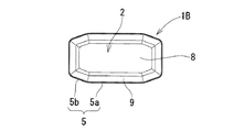
- a flat land 8 for seating is provided in the center portion surrounded by the groove 7 of the main surface 2. As shown in FIG. 1, when the height of the flat land 8 is lower than the cutting edge 5, the rake face (area along the cutting edge 5 of the main surface 2) 9 is inclined to sharpen the cutting edge. be able to.
- the flat land 8 and the cutting edge 5 may be aligned in height, and this form is advantageous in applications where the edge strength is important.
- the cutting insert 1 of FIG. 1 made the main side surface 3 the surface of a rectangle (the shape which disregarded the groove
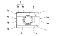
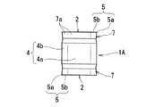
- the cutting insert 1A shown in FIGS. 6 to 9 is used for a front milling cutter, and the cutting edge 5 includes a secondary cutting edge 5b connected to the main cutting edge 5a at a predetermined angle.
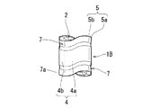
- the main side surface 3 can also be a parallelogram, as shown in FIGS.
- This form halves the number of corners used compared to the previously described form, but as shown in the figure, it changes the height position of the cutting edge 5 and suppresses the decrease in the strength of the cutting edge, while taking into account the sharpness and machining efficiency. Can be.
- An exemplary milling cutter 10 is a corner milling cutter using the cutting insert 1 of FIG.
Landscapes
- Engineering & Computer Science (AREA)
- Mechanical Engineering (AREA)
- Milling Processes (AREA)
Abstract
ミーリングカッタ用の切削インサートについて、良好な切れ味の確保と刃先強度の確保を両立させ、さらに、用途によっては使用コーナ数の増加の要求にも応えられるようにすることを課題としている。対向する多角形の2つの主面と、複数の側面を備え、前記主面をすくい面、側面を逃げ面、主面と側面が交差した位置の稜線を切れ刃として用いるミーリングカッタ用の切削インサートは、2つの互いに対向する主側面と、前記主側面に連なる複数の副側面を含み、前記2つの主側面は互いを貫通する方向に形成された取付け穴を有し、かつ前記主面よりも大面積であり、前記主側面と副側面に、切れ刃の全域に沿った溝がそれぞれ設けられている。
Description
この発明は、正面フライスカッタなどのミーリングカッタに採用する切削インサートに関する。
ミーリングカッタ用の切削インサートとして、例えば、下記特許文献1に記載されたものが知られている。
同文献に示された切削インサートは、通常、側面と称されている面をすくい面として使用するいわゆる縦使い方式である。
その切削インサートは、互いに背を向けた2つの側面をすくい面として使用可能となすために、取付け穴を貫通させた面(一般に上下面と称される面)を平坦で互いに平行な面にしている。ここで言う平坦で互いに平行な面とは、すくい面となす側面がフラットな場合、その側面とのなす角が90°になる面である。
そして、その形状で上下面の片方(例えば外周逃げ面となる側)に逃げ角を付与する(使用するコーナと反対側のコーナを被削材と干渉しない位置に逃がす)ために、ラジアルレーキが鈍くなる方向に切削インサートを傾けてカッタボディに装着して使用している。
また、前逃げ面となる面(すくい面となる側面と隣り合う位置の側面)にも逃げ角を付与するために、上下面を平行四辺形にしている。
平行四辺形の上下面を有する切削インサートは、上下面が方形の縦使いの切削インサートに比べて使用コーナ数が半減し、コスト面で不利である。
また、上下面が方形の切削インサートは全コーナを使用できる半面、この形状で前逃げ面となる面に逃げ角をつけるにはアキシャルレーキを鈍くする方向に切削インサートを傾けてカッタボディに装着する必要があり、切れ味の低下を招く。
この状況でアキシャルレーキも鈍くなると工具の切れ味は益々悪くなる。また、その不具合を補うためにすくい面を大きく傾斜させると、刃先強度が低下する。
以上の理由から、従来のミーリングカッタ用の縦使いの切削インサートは、良好な切れ味を確保すること、刃先強度を高めること、使用コーナ数を最大に増加させることの各要求を併せて満たす要求に十分に応えられていなかった。
この発明は、良好な切れ味を確保すること、刃先強度を高めること、使用コーナ数を最大に増加させることの各要求を併せて満たすことを課題としている。
上記の課題を解決するため、この発明においては、対向する多角形の2つの主面と、その主面の各辺に連なる複数の側面を備え、前記主面をすくい面、側面を逃げ面、主面と側面が交差した位置の稜線を切れ刃として用いるミーリングカッタ用の切削インサートを以下の通りに構成した。
即ち、前記複数の側面は、2つの互いに対向する主側面と、前記主側面に連なる複数の副側面を含み、前記2つの主側面は互いを貫通する方向に形成された取付け穴を有し、かつ前記主面よりも大面積であり、その主側面と副側面に、切れ刃の全域に沿った溝がそれぞれ設けられ、その溝の切れ刃に沿う側の溝面が前記切れ刃から遠ざかるにつれて深さが次第に深くなる方向に傾斜しているものにした。
即ち、前記複数の側面は、2つの互いに対向する主側面と、前記主側面に連なる複数の副側面を含み、前記2つの主側面は互いを貫通する方向に形成された取付け穴を有し、かつ前記主面よりも大面積であり、その主側面と副側面に、切れ刃の全域に沿った溝がそれぞれ設けられ、その溝の切れ刃に沿う側の溝面が前記切れ刃から遠ざかるにつれて深さが次第に深くなる方向に傾斜しているものにした。
この発明の切削インサートは、逃げ面となす側面に切れ刃に沿うブレーカ溝のような溝を設けており、その溝によって、刃先部近傍の逃げを十分に確保することができる。
そのために、工具設計の規制(カッタボディに対する切削インサートの装着姿勢の制限)が緩和され、アキシャルレーキやラジアルレーキの鈍化を抑えて良好な切れ味を確保することができる。
また、逃げ面の溝によって刃先部近傍の逃げを確保できるため、すくい面の傾斜角を大きくしてアキシャルレーキやラジアルレーキの鈍化を補う方法を採る必要がない。これにより、刃先強度確保も十分に確保することができる。
以下、この発明のミーリングカッタ用切削インサートの実施の形態を、添付図面の図1~図13に基づいて説明する。
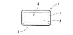
図1~図5は、隅削りフライスカッタなどに用いる切削インサートの一例である。この切削インサート1は、対向する多角形の2つの主面2,2と、両主面の各辺に連なる複数の側面を備えている。
図示の切削インサート1は、輪郭が長方形をなす主面2をすくい面として使用し、側面を逃げ面、主面2と側面が交差した位置の稜線を切れ刃5として用いる。
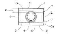
側面は、2つの互いに対向する主側面3,3と、両主側面3、3に連なる副側面4とを含む。両主側面3、3は、互いを貫通する方向に形成された取付け穴6を有する。また、主側面3は、片方を逃げ面、他方を支持座に対する着座面として使用する面であって、主面2よりも面積が大きい。
副側面4は、主面2の短辺と主側面3に連なっている。その副側面4は、主側面3が4つの辺を有する形状(基本形が方形又は平行四辺形)である場合にはその数が2面になる。主側面3の形状次第で副側面4の数は2以上に増える(主側面3の辺の総数から2を差し引いた数になる)。
主面2と主側面3が交差した位置の稜線と主面2と副側面4が交差した位置の稜線、即ち、主面2の全ての辺が切れ刃5として使用される。
その切れ刃5の全域に沿って主側面3と副側面4に溝7が設けられている。その溝7は、図5に示すように、切れ刃5に沿う側の溝面7aが切れ刃5から遠ざかるにつれて深さが次第に深くなる方向にθの角度で傾斜している。この傾きによって、切れ刃近傍の逃げ面(側面)に逃げ角が付与され、切削インサートをアキシャルレーキやラジアルレーキが鈍化する方向に傾けなくても切れ刃近傍の逃げ面の被削材との干渉が回避される。
この切削インサートは、溝7の溝面7aの傾斜角θを2°以上に設定すると被削材との干渉回避が確実になされて好ましい。傾斜角θの上限は、刃先強度の低下を抑えるために10°程度にするのがよい。
また、溝7の溝幅Wは0.5mm以上、5mm以下が好ましい。その溝幅Wを0.5mm以上とすることで、被削材との干渉を確実に回避することができる。
ここで言う主側面がすくい面となる姿勢にして使用するいわゆる平置きタイプの切削インサートでは、逃げ面となる面の厚み寸法が小さい。そのため、同様の溝をその面に設けようとすると干渉回避が確実になされるだけの溝幅を確保するのが難しい。しかし、縦使いの切削インサートでは、干渉回避に必要な溝幅を不足なく確保することができる。
その溝幅Wは、干渉回避の観点からは広いに越したことはないが、溝幅Wを無用に大きくすることは切削インサートの着座面の面積減少につながるので、溝幅Wは5mmを上限にするのがよい。
なお、主面2の溝7に囲まれる中央部には着座用のフラットランド8を設ける。そのフラットランド8は、図1に示すように、切れ刃5よりも高さ位置を低くすると、すくい面(主面2の切れ刃5に沿った領域)9を傾斜させて刃先を鋭利にすることができる。
フラットランド8と切れ刃5は、高さ位置が揃っていてもよく、刃先強度が重視される用途では、この形態が有利である。
なお、図1の切削インサート1は、主側面3を長方形(副側面4の溝7を無視した形状が長方形)の面にしたが、その主側面3は、四以上の偶数角を有する多角形にしてもよい。
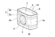
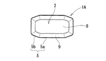
図6~図9の切削インサート1Aは、正面フライスカッタに採用するもので、切れ刃5に、主切れ刃5aに対して所定の角度をもって連なる副切れ刃5bを含ませている。
この切削インサート1Aは、副切れ刃5bがカッタの軸線に対して略垂直になる姿勢にしてカッタボディに装着し、主切れ刃5aを所定のアプローチ角を有する刃にして被削材を加工する。
この切削インサート1Aを有するフライスカッタを使用すると、加工面に形成される送りマークが副切れ刃5bによって除去され、加工面の精度が高められる。なお、副切れ刃5bは、用途に応じて設けるものであって、この発明の切削インサートの必須の要素ではない。
上述した2つの形態の切削インサート1は、180°の回転や180°の反転によって、主面のコーナが入れ替わり、回転前後、或いは、反転前後の主面の輪郭形状が重なる。
従って、右勝手の使用で4コーナ、左勝手の使用で4コーナの計8コーナの使用が可能である。主側面3は、図10~図13に示すように、平行四辺形にすることもできる。
この形態は、既述の形態に比べると使用コーナ数が半減するが、図に示すように、切れ刃5の高さ位置を変化させて刃先強度の低下を抑えながら切れ味や加工能率重視の形状にすることができる。
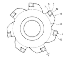
この発明のフライスカッタの一例を図14~図16に示す。例示のフライスカッタ10は、図1の切削インサート1を用いた隅削りフライスカッタである。
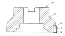
このフライスカッタ10は、主側面3と副側面4に溝7を設けたことによって、カッタボディ11の先端外周に設けられた支持座12に対する装着を、図14に示したアキシャルレーキγpと図15に示したラジアルレーキγを0°に近い値にして行うことができる。
そのために、良好な切れ味が確保され、さらに、刃先をきつく尖らせる必要がないため刃先強度も確保される。また、用途によっては、2つの主面2,2の全コーナを使用することが可能であり、工具コストの低減の要求にも応えることができる。
上記開示された本発明の実施形態の構成は、あくまで例示であって、本発明の範囲はこれらの記載の範囲に限定されるものではない。本発明の範囲は、請求の範囲の記載によって示され、さらに請求の範囲の記載と均等の意味及び範囲内でのすべての変更を含むものである。
1 切削インサート
2 主面
3 主側面
4 副側面
5 切れ刃
6 取付け穴
7 溝
8 フラットランド
9 すくい面(主面の切れ刃に沿った領域)
W 溝幅
10 隅削りフライスカッタ
11 カッタボディ
12 支持座
13 クランプねじ
2 主面
3 主側面
4 副側面
5 切れ刃
6 取付け穴
7 溝
8 フラットランド
9 すくい面(主面の切れ刃に沿った領域)
W 溝幅
10 隅削りフライスカッタ
11 カッタボディ
12 支持座
13 クランプねじ
Claims (3)
- 対向する多角形の2つの主面と、その主面の各辺に連なる複数の側面を備え、前記主面をすくい面、側面を逃げ面、前記主面と前記側面が交差した位置の稜線を切れ刃として用いるミーリングカッタ用の切削インサートであって、
前記複数の側面は、2つの互いに対向する主側面と、前記主側面に連なる複数の副側面を含み、前記2つの主側面は互いを貫通する方向に形成された取付け穴を有し、かつ前記主面よりも大面積であり、
前記主側面と前記副側面は、切れ刃の全域に沿って溝がそれぞれ設けられ、その溝の切れ刃に沿う側の溝面が前記切れ刃から遠ざかるにつれて深さが次第に深くなる方向に傾斜しているミーリングカッタ用切削インサート。 - 前記溝の切れ刃に沿う側の溝面の傾斜角を2°以上にし、さらに、前記溝の溝幅を、0.5mm以上、5mm以下に設定した請求項1に記載のミーリングカッタ用切削インサート。
- 前記主面の中央部にカッタボディの支持座に対して着座させるフラットランドを設け、前記フラットランドの位置を前記切れ刃の位置よりも低くして前記切れ刃と前記フラットランド間に傾斜したすくい面を設置した請求項1又は2に記載のミーリングカッタ用切削インサート。
Priority Applications (4)
| Application Number | Priority Date | Filing Date | Title |
|---|---|---|---|
| ES14773792T ES2739388T3 (es) | 2013-03-26 | 2014-01-16 | Inserto de corte para fresas |
| US14/409,626 US9630264B2 (en) | 2013-03-26 | 2014-01-16 | Cutting insert for a milling cutter |
| EP14773792.8A EP2979800B1 (en) | 2013-03-26 | 2014-01-16 | Cutting insert for milling cutters |
| CN201480001929.4A CN104507611A (zh) | 2013-03-26 | 2014-01-16 | 用于铣刀的切削刀具 |
Applications Claiming Priority (2)
| Application Number | Priority Date | Filing Date | Title |
|---|---|---|---|
| JP2013-063621 | 2013-03-26 | ||
| JP2013063621A JP6127343B2 (ja) | 2013-03-26 | 2013-03-26 | ミーリングカッタ用切削インサート |
Publications (1)
| Publication Number | Publication Date |
|---|---|
| WO2014156224A1 true WO2014156224A1 (ja) | 2014-10-02 |
Family
ID=51623230
Family Applications (1)
| Application Number | Title | Priority Date | Filing Date |
|---|---|---|---|
| PCT/JP2014/050622 Ceased WO2014156224A1 (ja) | 2013-03-26 | 2014-01-16 | ミーリングカッタ用切削インサート |
Country Status (6)
| Country | Link |
|---|---|
| US (1) | US9630264B2 (ja) |
| EP (1) | EP2979800B1 (ja) |
| JP (1) | JP6127343B2 (ja) |
| CN (1) | CN104507611A (ja) |
| ES (1) | ES2739388T3 (ja) |
| WO (1) | WO2014156224A1 (ja) |
Cited By (1)
| Publication number | Priority date | Publication date | Assignee | Title |
|---|---|---|---|---|
| US20150117969A1 (en) * | 2013-10-29 | 2015-04-30 | Kennametal Inc. | Cutting insert and shim for heavy machining operations |
Families Citing this family (11)
| Publication number | Priority date | Publication date | Assignee | Title |
|---|---|---|---|---|
| JP2014076511A (ja) * | 2012-10-10 | 2014-05-01 | Sumitomo Electric Hardmetal Corp | 切削用インサート及び切削工具 |
| KR101517979B1 (ko) * | 2014-07-08 | 2015-05-06 | 한국야금 주식회사 | 절삭 인서트 및 이를 장착한 절삭 공구 |
| KR101556737B1 (ko) | 2014-10-21 | 2015-10-01 | 한국야금 주식회사 | 절삭 인서트 및 이를 장착한 절삭 공구 |
| KR101814642B1 (ko) * | 2015-11-04 | 2018-01-03 | 한국야금 주식회사 | 고이송 양면형 절삭 인서트 및 이를 장착한 절삭 공구 |
| WO2018061227A1 (ja) * | 2016-09-27 | 2018-04-05 | 株式会社タンガロイ | 切削インサートおよび切削工具 |
| US10421134B2 (en) * | 2016-11-17 | 2019-09-24 | Kennametal Inc. | Tangentially mounted indexable cutting insert with convex-shaped minor side surfaces and concave-shaped end surfaces |
| US10518339B2 (en) * | 2017-03-22 | 2019-12-31 | Kennametal Inc. | Tangentially mounted cutting insert with angled seating surface and recessed clearance surface |
| US10525537B2 (en) * | 2017-11-17 | 2020-01-07 | Iscar Ltd. | Rotary cutting tool having disk-shaped cutting body and indexable cutting insert therefor |
| JP6972513B1 (ja) * | 2021-02-10 | 2021-11-24 | 株式会社タンガロイ | 切削インサート |
| WO2023063184A1 (ja) * | 2021-10-11 | 2023-04-20 | 京セラ株式会社 | 切削インサート、切削工具及び切削加工物の製造方法 |
| JP7205707B1 (ja) | 2022-06-03 | 2023-01-17 | 株式会社タンガロイ | 切削インサート、及び切削インサートを備える切削工具 |
Citations (4)
| Publication number | Priority date | Publication date | Assignee | Title |
|---|---|---|---|---|
| JP2004291205A (ja) | 2003-03-28 | 2004-10-21 | Sumitomo Electric Ind Ltd | 刃先交換式チップ及びそれを用いた隅削りフライスカッタ |
| JP2009107051A (ja) * | 2007-10-30 | 2009-05-21 | Tungaloy Corp | スローアウェイチップおよびこれを用いたスローアウェイ式切削工具 |
| US20090155004A1 (en) * | 2007-12-13 | 2009-06-18 | Seco Tools Ab | Cutting insert and tool for chip removing machining |
| JP2012161907A (ja) * | 2011-01-18 | 2012-08-30 | Mitsubishi Materials Corp | 切削インサートおよび刃先交換式切削工具 |
Family Cites Families (21)
| Publication number | Priority date | Publication date | Assignee | Title |
|---|---|---|---|---|
| US4074949A (en) * | 1975-09-19 | 1978-02-21 | Robert Zapp, Werkzeug-Und Maschinenfabrik Gmbh | Cutting tool |
| US4789273A (en) * | 1987-03-02 | 1988-12-06 | General Motors Of Canada Ltd. | Milling cutter |
| US5876160A (en) * | 1996-08-21 | 1999-03-02 | Ingersoll Cutting Tool Company | Milling with insert having cutting-edge land of width increasing with depth of cut |
| IL129297A (en) * | 1998-07-13 | 2002-12-01 | Iscar Ltd | Tangential cutting insert |
| IL140104A (en) | 2000-12-05 | 2006-06-11 | Amir Satran | Rotary cutting tool |
| SE0301827L (sv) * | 2002-12-04 | 2004-06-05 | Chalmers Technology Licensing | Verktyg |
| DE10317760B4 (de) * | 2003-04-17 | 2005-08-25 | Walter Ag | Fräswerkzeug und Schneidplatte für ein solches |
| IL160223A (en) * | 2004-02-04 | 2008-11-26 | Carol Smilovici | Double-sided cutting insert and milling cutter |
| IL166530A (en) * | 2005-01-27 | 2009-06-15 | Iscar Ltd | Method for manufacturing cutting inserts |
| JP2006272479A (ja) * | 2005-03-28 | 2006-10-12 | Kyocera Corp | スローアウェイチップ及びそれを用いた高送り用ミーリングカッター |
| JP4491404B2 (ja) * | 2005-11-07 | 2010-06-30 | 住友電工ハードメタル株式会社 | 刃先交換式チップと刃先交換式隅削りフライスカッタ |
| JP2008229745A (ja) * | 2007-03-16 | 2008-10-02 | Mitsubishi Materials Corp | 切削インサートおよびインサート着脱式転削工具 |
| MX2009013985A (es) | 2007-06-21 | 2010-04-09 | Ceramtec Ag | Inserto negativo que tiene doble superficie de separacion positiva. |
| IL187721A (en) * | 2007-11-28 | 2014-05-28 | Iscar Ltd | Cutting insert |
| DE102008002406A1 (de) * | 2008-06-12 | 2009-12-17 | Sandvik Gmbh | Schneidwerkzeug und Verfahren zum spanhebenden Bearbeiten von metallischen Werkstücken |
| KR100985597B1 (ko) * | 2008-08-20 | 2010-10-05 | 대구텍 유한회사 | 절삭 인서트 및 이러한 절삭 인서트가 적용된 밀링커터 |
| US7922427B2 (en) * | 2008-12-18 | 2011-04-12 | Kennametal Inc. | Toolholder and toolholder assembly with elongated seating pads |
| US8061241B2 (en) * | 2009-04-06 | 2011-11-22 | Creare Incorporated | Indirect cooling of a cutting tool |
| IL198726A (en) * | 2009-05-13 | 2014-04-30 | Iscar Ltd | Sheet and cutting tools for her |
| DE102011107789B4 (de) | 2011-07-18 | 2015-05-28 | Kennametal Inc. | Zahnradfräser-Schneideinsatz und Zahnradfräser mit einem solchen Zahnradfräser-Schneideinsatz |
| KR101380884B1 (ko) * | 2012-06-14 | 2014-04-02 | 한국야금 주식회사 | 양면형 절삭 인서트 |
-
2013
- 2013-03-26 JP JP2013063621A patent/JP6127343B2/ja active Active
-
2014
- 2014-01-16 WO PCT/JP2014/050622 patent/WO2014156224A1/ja not_active Ceased
- 2014-01-16 US US14/409,626 patent/US9630264B2/en active Active
- 2014-01-16 EP EP14773792.8A patent/EP2979800B1/en active Active
- 2014-01-16 ES ES14773792T patent/ES2739388T3/es active Active
- 2014-01-16 CN CN201480001929.4A patent/CN104507611A/zh active Pending
Patent Citations (4)
| Publication number | Priority date | Publication date | Assignee | Title |
|---|---|---|---|---|
| JP2004291205A (ja) | 2003-03-28 | 2004-10-21 | Sumitomo Electric Ind Ltd | 刃先交換式チップ及びそれを用いた隅削りフライスカッタ |
| JP2009107051A (ja) * | 2007-10-30 | 2009-05-21 | Tungaloy Corp | スローアウェイチップおよびこれを用いたスローアウェイ式切削工具 |
| US20090155004A1 (en) * | 2007-12-13 | 2009-06-18 | Seco Tools Ab | Cutting insert and tool for chip removing machining |
| JP2012161907A (ja) * | 2011-01-18 | 2012-08-30 | Mitsubishi Materials Corp | 切削インサートおよび刃先交換式切削工具 |
Cited By (1)
| Publication number | Priority date | Publication date | Assignee | Title |
|---|---|---|---|---|
| US20150117969A1 (en) * | 2013-10-29 | 2015-04-30 | Kennametal Inc. | Cutting insert and shim for heavy machining operations |
Also Published As
| Publication number | Publication date |
|---|---|
| US20160039015A1 (en) | 2016-02-11 |
| JP6127343B2 (ja) | 2017-05-17 |
| ES2739388T3 (es) | 2020-01-30 |
| EP2979800A1 (en) | 2016-02-03 |
| EP2979800B1 (en) | 2019-06-19 |
| JP2014188595A (ja) | 2014-10-06 |
| EP2979800A4 (en) | 2016-03-09 |
| CN104507611A (zh) | 2015-04-08 |
| US9630264B2 (en) | 2017-04-25 |
Similar Documents
| Publication | Publication Date | Title |
|---|---|---|
| JP6127343B2 (ja) | ミーリングカッタ用切削インサート | |
| KR101097658B1 (ko) | 절삭 삽입체 | |
| JP6352181B2 (ja) | 切削インサートとそれを用いた正面フライスカッタ | |
| CN102905824B (zh) | 切削刀片 | |
| JP6132178B2 (ja) | 切削インサートおよび切削工具 | |
| JP5227342B2 (ja) | 切削インサートおよび切削工具、並びに切削方法 | |
| JP5401732B1 (ja) | フライス加工用刃先交換式切削インサート | |
| KR20140004149A (ko) | 접선 절삭 인서트 및 밀링 커터 | |
| WO2011046045A1 (ja) | 切削インサート | |
| JP2014524365A (ja) | フライス用両面切削インサート | |
| WO2016060195A1 (ja) | 切削インサート及び刃先交換式回転切削工具 | |
| JP5904346B2 (ja) | 切削工具用ボデーおよび該ボデーを適用した切削工具 | |
| WO2010147065A1 (ja) | 切削用インサートおよび刃先交換式正面フライス | |
| JPH04115521U (ja) | 転削工具 | |
| JP3196566B2 (ja) | スローアウェイチップ及びスローアウェイ式カッタ | |
| JP5979054B2 (ja) | ドリル用インサートおよび刃先交換式ドリル | |
| JP3180604B2 (ja) | スローアウェイチップ及びスローアウェイ式カッタ | |
| JP2017154227A (ja) | 切削インサートおよび切削工具 | |
| JP2008254127A (ja) | 切削インサート | |
| JPH07237025A (ja) | スローアウェイチップ | |
| JPH0839306A (ja) | スローアウェイチップ | |
| JP7778293B1 (ja) | 切削インサート及び回転切削工具 | |
| KR102855563B1 (ko) | 절삭 인서트 및 이를 포함하는 절삭 공구 | |
| CN111545840B (zh) | 切削刀片 | |
| JP2020163501A (ja) | 切削インサートおよび刃先交換式カッター |
Legal Events
| Date | Code | Title | Description |
|---|---|---|---|
| 121 | Ep: the epo has been informed by wipo that ep was designated in this application |
Ref document number: 14773792 Country of ref document: EP Kind code of ref document: A1 |
|
| WWE | Wipo information: entry into national phase |
Ref document number: 14409626 Country of ref document: US |
|
| WWE | Wipo information: entry into national phase |
Ref document number: 2014773792 Country of ref document: EP |
|
| NENP | Non-entry into the national phase |
Ref country code: DE |