WO2014156314A1 - 燃料電池 - Google Patents
燃料電池 Download PDFInfo
- Publication number
- WO2014156314A1 WO2014156314A1 PCT/JP2014/052659 JP2014052659W WO2014156314A1 WO 2014156314 A1 WO2014156314 A1 WO 2014156314A1 JP 2014052659 W JP2014052659 W JP 2014052659W WO 2014156314 A1 WO2014156314 A1 WO 2014156314A1
- Authority
- WO
- WIPO (PCT)
- Prior art keywords
- power generation
- fuel gas
- cell
- fuel
- path
- Prior art date
- Legal status (The legal status is an assumption and is not a legal conclusion. Google has not performed a legal analysis and makes no representation as to the accuracy of the status listed.)
- Ceased
Links
Images


Classifications
-
- H—ELECTRICITY
- H01—ELECTRIC ELEMENTS
- H01M—PROCESSES OR MEANS, e.g. BATTERIES, FOR THE DIRECT CONVERSION OF CHEMICAL ENERGY INTO ELECTRICAL ENERGY
- H01M8/00—Fuel cells; Manufacture thereof
- H01M8/24—Grouping of fuel cells, e.g. stacking of fuel cells
- H01M8/2457—Grouping of fuel cells, e.g. stacking of fuel cells with both reactants being gaseous or vaporised
-
- H—ELECTRICITY
- H01—ELECTRIC ELEMENTS
- H01M—PROCESSES OR MEANS, e.g. BATTERIES, FOR THE DIRECT CONVERSION OF CHEMICAL ENERGY INTO ELECTRICAL ENERGY
- H01M8/00—Fuel cells; Manufacture thereof
- H01M8/02—Details
- H01M8/0202—Collectors; Separators, e.g. bipolar separators; Interconnectors
- H01M8/0258—Collectors; Separators, e.g. bipolar separators; Interconnectors characterised by the configuration of channels, e.g. by the flow field of the reactant or coolant
-
- H—ELECTRICITY
- H01—ELECTRIC ELEMENTS
- H01M—PROCESSES OR MEANS, e.g. BATTERIES, FOR THE DIRECT CONVERSION OF CHEMICAL ENERGY INTO ELECTRICAL ENERGY
- H01M8/00—Fuel cells; Manufacture thereof
- H01M8/02—Details
- H01M8/0202—Collectors; Separators, e.g. bipolar separators; Interconnectors
- H01M8/0267—Collectors; Separators, e.g. bipolar separators; Interconnectors having heating or cooling means, e.g. heaters or coolant flow channels
-
- H—ELECTRICITY
- H01—ELECTRIC ELEMENTS
- H01M—PROCESSES OR MEANS, e.g. BATTERIES, FOR THE DIRECT CONVERSION OF CHEMICAL ENERGY INTO ELECTRICAL ENERGY
- H01M8/00—Fuel cells; Manufacture thereof
- H01M8/04—Auxiliary arrangements, e.g. for control of pressure or for circulation of fluids
- H01M8/04007—Auxiliary arrangements, e.g. for control of pressure or for circulation of fluids related to heat exchange
- H01M8/04067—Heat exchange or temperature measuring elements, thermal insulation, e.g. heat pipes, heat pumps, fins
- H01M8/04074—Heat exchange unit structures specially adapted for fuel cell
-
- H—ELECTRICITY
- H01—ELECTRIC ELEMENTS
- H01M—PROCESSES OR MEANS, e.g. BATTERIES, FOR THE DIRECT CONVERSION OF CHEMICAL ENERGY INTO ELECTRICAL ENERGY
- H01M8/00—Fuel cells; Manufacture thereof
- H01M8/24—Grouping of fuel cells, e.g. stacking of fuel cells
- H01M8/241—Grouping of fuel cells, e.g. stacking of fuel cells with solid or matrix-supported electrolytes
- H01M8/2425—High-temperature cells with solid electrolytes
-
- H—ELECTRICITY
- H01—ELECTRIC ELEMENTS
- H01M—PROCESSES OR MEANS, e.g. BATTERIES, FOR THE DIRECT CONVERSION OF CHEMICAL ENERGY INTO ELECTRICAL ENERGY
- H01M8/00—Fuel cells; Manufacture thereof
- H01M8/24—Grouping of fuel cells, e.g. stacking of fuel cells
- H01M8/2465—Details of groupings of fuel cells
- H01M8/247—Arrangements for tightening a stack, for accommodation of a stack in a tank or for assembling different tanks
-
- H—ELECTRICITY
- H01—ELECTRIC ELEMENTS
- H01M—PROCESSES OR MEANS, e.g. BATTERIES, FOR THE DIRECT CONVERSION OF CHEMICAL ENERGY INTO ELECTRICAL ENERGY
- H01M8/00—Fuel cells; Manufacture thereof
- H01M8/24—Grouping of fuel cells, e.g. stacking of fuel cells
- H01M8/2465—Details of groupings of fuel cells
- H01M8/2483—Details of groupings of fuel cells characterised by internal manifolds
-
- H—ELECTRICITY
- H01—ELECTRIC ELEMENTS
- H01M—PROCESSES OR MEANS, e.g. BATTERIES, FOR THE DIRECT CONVERSION OF CHEMICAL ENERGY INTO ELECTRICAL ENERGY
- H01M8/00—Fuel cells; Manufacture thereof
- H01M8/10—Fuel cells with solid electrolytes
- H01M8/12—Fuel cells with solid electrolytes operating at high temperature, e.g. with stabilised ZrO2 electrolyte
- H01M2008/1293—Fuel cells with solid oxide electrolytes
-
- H—ELECTRICITY
- H01—ELECTRIC ELEMENTS
- H01M—PROCESSES OR MEANS, e.g. BATTERIES, FOR THE DIRECT CONVERSION OF CHEMICAL ENERGY INTO ELECTRICAL ENERGY
- H01M8/00—Fuel cells; Manufacture thereof
- H01M8/04—Auxiliary arrangements, e.g. for control of pressure or for circulation of fluids
- H01M8/04007—Auxiliary arrangements, e.g. for control of pressure or for circulation of fluids related to heat exchange
- H01M8/04014—Heat exchange using gaseous fluids; Heat exchange by combustion of reactants
- H01M8/04022—Heating by combustion
-
- H—ELECTRICITY
- H01—ELECTRIC ELEMENTS
- H01M—PROCESSES OR MEANS, e.g. BATTERIES, FOR THE DIRECT CONVERSION OF CHEMICAL ENERGY INTO ELECTRICAL ENERGY
- H01M8/00—Fuel cells; Manufacture thereof
- H01M8/24—Grouping of fuel cells, e.g. stacking of fuel cells
- H01M8/241—Grouping of fuel cells, e.g. stacking of fuel cells with solid or matrix-supported electrolytes
- H01M8/2425—High-temperature cells with solid electrolytes
- H01M8/2432—Grouping of unit cells of planar configuration
-
- Y—GENERAL TAGGING OF NEW TECHNOLOGICAL DEVELOPMENTS; GENERAL TAGGING OF CROSS-SECTIONAL TECHNOLOGIES SPANNING OVER SEVERAL SECTIONS OF THE IPC; TECHNICAL SUBJECTS COVERED BY FORMER USPC CROSS-REFERENCE ART COLLECTIONS [XRACs] AND DIGESTS
- Y02—TECHNOLOGIES OR APPLICATIONS FOR MITIGATION OR ADAPTATION AGAINST CLIMATE CHANGE
- Y02E—REDUCTION OF GREENHOUSE GAS [GHG] EMISSIONS, RELATED TO ENERGY GENERATION, TRANSMISSION OR DISTRIBUTION
- Y02E60/00—Enabling technologies; Technologies with a potential or indirect contribution to GHG emissions mitigation
- Y02E60/30—Hydrogen technology
- Y02E60/50—Fuel cells
Definitions
- the present invention relates to a fuel cell.
- a solid oxide fuel cell (hereinafter also abbreviated as SOFC) using a solid electrolyte (solid oxide) is known as a fuel cell.
- SOFC solid oxide fuel cell
- a fuel electrode provided with a fuel electrode in contact with the fuel gas on one side of the solid electrolyte membrane and an oxidant electrode (air electrode) in contact with the oxidant gas (air) on the other side is provided.
- Battery cells power generation cells
- a fuel cell in which a plurality of power generation cells are stacked via an interconnector has been developed.
- This type of fuel cell usually has a problem that the temperature of the power generation cell on the center side in the direction in which the power generation cells are stacked (stacking direction) is higher than the temperature of the power generation cell on the end side. Therefore, a technique has been proposed in which cold air is supplied to one side surface on the center side in the stacking direction, and hot gas exchanged heat is applied to the end of the fuel cell in the stacking direction (patent). Reference 1).
- the power generation cell located on the center side in the stacking direction of the fuel cells cannot be sufficiently cooled.
- the utilization rate of the fuel gas cannot be sufficiently increased.
- a fuel cell includes a plurality of stacked power generation cells, a heat exchange section provided between two adjacent power generation cells, and a fuel gas supply that supplies fuel gas to the power generation cells A path and an oxidant gas supply path for supplying an oxidant gas to the power generation cell.
- the fuel gas supply path includes a first path that passes through the heat exchange unit, a second path that passes through some of the plurality of power generation cells in parallel, and the plurality of power generation cells.
- the third path is a path that includes in series a third path that passes in parallel through the plurality of power generation cells.
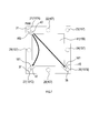
- the position of the inlet of the fuel gas in each power generation cell is two first positions PA and second positions PB along one side of the power generation cell when viewed from the stacking direction.
- the position of the fuel gas outlet is one third position PC on the side facing the one side.
- the position of the fuel gas inlet in each power generation cell is a position overlapping the third position PC when viewed from the stacking direction, and the position of the fuel gas outlet is , A position between the first position PA and the second position PB.
- a fuel cell includes a plurality of stacked power generation cells, a power generation cell positioned between two adjacent power generation cells, and an end of the plurality of power generation cells in the stacking direction.
- a heat exchange section provided on at least one of the outer sides; a fuel gas supply path for supplying fuel gas to the power generation cell; and an oxidant gas supply path for supplying oxidant gas to the power generation cell.
- the fuel gas supply path includes a first path that passes through the heat exchange unit, a second path that passes through some of the plurality of power generation cells in parallel, and the plurality of power generation cells.
- the third path is a path that includes in series a third path that passes in parallel through the plurality of power generation cells.
- the position of the inlet of the fuel gas in each power generation cell is two first positions PA and second positions PB along one side of the power generation cell when viewed from the stacking direction.
- the position of the fuel gas outlet is one third position PC on the side facing the one side.
- the position of the fuel gas inlet in each power generation cell is a position overlapping the third position PC when viewed from the stacking direction, and the position of the fuel gas outlet is , A position between the first position PA and the second position PB.
- the fuel cell according to the first aspect of the present invention includes a heat exchange part provided between two power generation cells, and can effectively cool the power generation cell by flowing fuel gas through the heat exchange part.
- the fuel cell according to the second aspect of the present invention includes a heat exchange portion provided between at least two adjacent power generation cells and at least one of the plurality of power generation cells outside the power generation cell located at the end in the stacking direction.
- the power generation cell can be effectively cooled by supplying the fuel gas to the heat exchanging portion.
- the heat exchange section is provided in at least one of “between two adjacent power generation cells”, “outside of the upper end in the stacking direction of the power generation cells”, and “outside of the lower end in the stacking direction of the power generation cells”. Yes.
- the heat exchange unit may be provided at any two of the three locations, or may be provided at all of the three locations.
- the fuel gas supply path includes the first path, the second path through which the fuel gas flows in parallel, and the third path in series. Since this is a route including the fuel utilization rate is high.
- the positions of the inlet and outlet of the fuel gas in each power generation cell in the second path and the third path are arranged as described above.
- the fuel gas can be made to flow uniformly in the power generation cell to generate power uniformly.
- the fuel gas supply path includes a plurality of fuel gas passages extending in the direction of stacking in the fuel cell, and a plurality of power generation cells from the fuel gas passage.
- the inside of at least one of the power generation cells or a connection port connected to the heat exchange unit may be provided, and the inlet and the outlet may be a part of the connection port.
- the manifold can be shared and the number of parts can be reduced.
- the fuel cell is provided with a plurality of bolts that penetrate the fuel cell in the stacking direction and fix the plurality of power generation cells and the heat exchange unit.
- the gas passage may be a cavity formed in the plurality of bolts. In this case, since the fuel gas passage is provided inside the bolt, the entire fuel cell can be reduced in size.
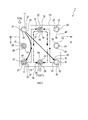
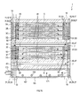
- FIG. 1 is a plan view illustrating a configuration of a fuel cell 1 according to a first embodiment, illustrating a flow of fuel gas.
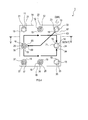
- 1 is a plan view illustrating a configuration of a fuel cell 1 according to a first embodiment, showing an air flow.
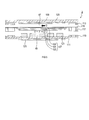
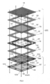
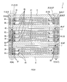
- FIG. 5 is a cross-sectional view of the power generation cell 3 taken along the line VV in FIGS. 3 and 4. It is an exploded view showing the structure of power generation cell 3D and the heat exchange part 7.
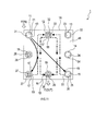
- FIG. 4 is a plan view showing the flow of fuel gas in the heat exchanging unit 7.
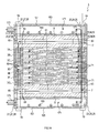
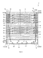
- FIG. FIG. 6 is a plan view illustrating the air flow in the heat exchange unit 7. It is sectional drawing showing the structure of the fuel cell 1 in 2nd Embodiment, Comprising: It is drawing which showed the flow of fuel gas. It is sectional drawing showing the structure of the fuel cell 1 in 2nd Embodiment, Comprising: It is drawing which showed the flow of air. It is a top view showing the structure of the fuel cell 1 in 2nd Embodiment, Comprising: It is drawing which showed the flow of fuel gas. It is a top view showing the structure of the fuel cell 1 in 2nd Embodiment, Comprising: It is drawing which showed the flow of air.
- the fuel cell 1 is a solid oxide fuel cell, and is a device that generates power by receiving supply of fuel gas (for example, hydrogen) and air (corresponding to an example of an oxidant gas).
- fuel gas for example, hydrogen
- air corresponding to an example of an oxidant gas
- the fuel cell 1 includes a flat plate fuel cell (hereinafter referred to as a power generation cell) 3 that is a power generation unit, a heat exchange unit 7, and a pair of end plates 8 and 9. It has a laminated structure.
- power generation cells 3 There are eight power generation cells 3, which are 3A, 3B, 3C, 3D, 3E, 3F, 3G, and 3H in order from the top in FIGS.
- the heat exchange part 7 is located between the power generation cells 3D and 3E and is in contact with them. That is, four power generation cells 3 are stacked above and below the heat exchange unit 7.
- the end plate 8 is located outside the power generation cell 3A (the upper side in FIGS. 1 and 2) and is in contact with the power generation cell 3A.
- the end plate 9 is located outside the power generation cell 3H (the lower side in FIGS. 1 and 2) and is in contact with the power generation cell 3H.
- the fuel cell 1 (that is, the power generation cell 3, the heat exchange unit 7, and the end plates 8 and 9) has a stacking direction of the power generation cells 3 (up and down direction in FIGS. 1 and 2, When viewed from the direction orthogonal to the paper surface in FIGS. 3 and 4, it has a rectangular shape.
- the fuel cell 1 has eight holes 11 to 18 penetrating it in the stacking direction.
- the holes 11 to 18 are formed by holes provided in each of the power generation cell 3, the heat exchange unit 7, and the end plates 8 and 9 constituting the fuel cell 1.
- the holes 11, 12, and 13 are formed at equal intervals along one side 1A constituting the outer shape of the fuel cell 1, and the hole 12 is in the middle of the side 1A.
- the holes 15, 16, and 17 are formed at equal intervals along the side 1 ⁇ / b> B facing the side 1 ⁇ / b> A, and the hole 16 is located in the middle of the holes 15 and 17.
- Bolts 21 are inserted into the holes 11 and nuts 19 are screwed to both ends thereof.
- the bolt 21 reaches from one end of the fuel cell 1 to the other end in the stacking direction.
- bolts 22 to 28 are inserted into the holes 12 to 18, respectively, and nuts 19 are screwed to both ends thereof.
- the power generation cell 3 and the heat exchange unit 7 are fixed by bolts 21 to 28 and a nut 19.
- Each of the bolts 21 to 28 includes hollow gas passages 31 to 38 therein.
- the gas passages 31 to 38 extend along the axial direction of the bolts 21 to 28, respectively, and extend from one end thereof to the other end.
- the gas passages 31, 32, 35, 36, and 37 correspond to an example of a fuel gas passage.
- the bolt 21 reaches an outer surface of the bolt 21 from the gas passage 31, and has an inlet 43 that is a hole connected to a fuel gas passage 41 (described later) in the heat exchange unit 7. I have.
- the bolt 25 includes an outlet 45 that is a hole connecting from the gas passage 35 to the outer surface of the bolt 25 and connected to the fuel gas passage 41.
- the bolt 27 includes an outlet 47 that is a hole connecting from the gas passage 37 to the outer surface of the bolt 27 and connected to the fuel gas passage 41.
- the bolt 25 includes five inlets 51 that are holes extending from the gas passage 35 to the outer surface of the bolt 25.
- the five inlets 51 are arranged at equal intervals along the vertical direction in FIG. 1 and communicate with a fuel gas flow path 49 in the power generation cell described later in the power generation cells 3A, 3B, 3C, 3D, and 3E, respectively. ing.
- the bolt 27 includes five inlets 53 that are holes extending from the gas passage 37 to the outer surface of the bolt 27.
- the five inlets 53 are arranged at equal intervals along the vertical direction in FIG. 1 and communicate with the fuel gas flow passages 49 in the power generation cells 3A, 3B, 3C, 3D, and 3E, respectively. .
- the bolt 22 includes five outlets 55 that are holes extending from the gas passage 32 to the outer surface of the bolt 22.
- the five outlets 55 are arranged at equal intervals along the vertical direction in FIG. 1, and communicate with a fuel gas flow path 49 in the power generation cell described later in the power generation cells 3A, 3B, 3C, 3D, and 3E, respectively. ing.
- the bolt 22 includes three inlets 57 that are holes extending from the gas passage 32 to the outer surface of the bolt 22.
- the three inlets 57 are arranged at equal intervals in the vertical direction in FIG. 1 and communicate with the power generation cell fuel gas flow paths 49 in the power generation cells 3F, 3G, and 3H, respectively.
- the bolt 26 includes three outlets 59 that are holes extending from the gas passage 36 to the outer surface of the bolt 26.
- the three outlets 59 are arranged at equal intervals along the vertical direction in FIG. 1, and communicate with the power generation cell fuel gas flow paths 49 in the power generation cells 3F, 3G, and 3H, respectively.
- the bolt 23 reaches the outer surface of the bolt 23 from the gas passage 33, and is an inlet 63 that is a hole connected to an air flow path 61 described later in the heat exchange unit 7. It has.
- the bolt 28 includes an outlet 65 that is a hole connecting from the gas passage 38 to the outer surface of the bolt 28 and connected to the air flow path 61.
- the bolt 28 includes eight inlets 69 that are holes extending from the gas passage 38 to the outer surface of the bolt 28.
- the eight inlets 69 are arranged at predetermined intervals along the vertical direction in FIG. 1, and the power generation cells described later in the power generation cells 3A, 3B, 3C, 3D, 3E, 3F, 3G, and 3H, respectively. It communicates with the internal air flow path 67.
- the bolt 24 includes eight outlets 71 that are holes extending from the gas passage 34 to the outer surface of the bolt 24.
- the eight outlets 71 are arranged at predetermined intervals along the vertical direction in FIG. 2, and the air in the power generation cells in the power generation cells 3A, 3B, 3C, 3D, 3E, 3F, 3G, and 3H, respectively. It communicates with the channel 67.
- Each outlet and each inlet described above correspond to an example of a connection port.
- FIG. 6 illustrates the configuration of the power generation cell 3 ⁇ / b> D among the power generation cells 3.
- the power generation cell 3 is a so-called fuel electrode support membrane type plate-like cell.
- the power generation cell 3 includes a thin-film solid electrolyte body 101, and a fuel electrode (anode) 103 and a thin-film air electrode (cathode) 105 formed on both sides thereof.
- the solid electrolyte body 101, the fuel electrode 103, and the air electrode 105 are collectively referred to as a cell body 107.
- a power generation cell air flow path 67 exists on the air electrode 105 side of the cell body 107, and a power generation cell fuel gas flow path 49 exists on the fuel electrode 103 side.
- the power generation cell 3 is joined to the upper surface of the pair of upper and lower interconnectors 109 and 111, the plate-shaped gas seal portion 113 on the air electrode 105 side, and the outer edge portion of the cell body 107, and the air flow path 67 in the power generation cell. And a separator 115 that shuts off the fuel gas flow path 49 in the power generation cell, a fuel electrode frame 117 disposed on the fuel gas flow path 49 in the power generation cell, and a gas seal portion 119 on the fuel electrode 103 side. These are laminated to form a single unit.
- a fuel electrode side current collector 121 is disposed between the fuel electrode 103 and the interconnector 111, and an air electrode side current collector 123 is integrally formed on the surface of the interconnector 109. ing.
- the material of the solid electrolyte body 101 materials such as YSZ, ScSZ, SDC, GDC, and perovskite oxide can be used.
- the fuel electrode 103 cermets of N and Ni and ceramics can be used, and as the air electrode 105, perovskite oxides, cermets of various precious metals and ceramics can be used.
- the interconnectors 109 and 111 are plate materials made of ferritic stainless steel, and eight holes 125 corresponding to the holes 11 to 18 are provided on the outer edge portion thereof.
- the gas seal portion 113 is made of mica or vermulite and is a frame-shaped plate material having a square opening 127 at the center. Eight holes 129 corresponding to the holes 11 to 18 are provided on the outer edge thereof. ing. Two of the holes 129 corresponding to the holes 14 and 18 and the opening 127 communicate with each other through a communication groove 131.
- the communication groove 131 is not a groove penetrating the gas seal portion 113 in the thickness direction, but a groove formed by digging one surface of the gas seal portion 113 and can be formed by laser or pressing.
- the separator 115 is a frame-shaped plate material made of ferritic stainless steel, and has a square opening 133 at the center thereof.
- the cell body 107 is bonded to the separator 115 so as to close the opening 133.
- the separator 115 also has eight holes 135 corresponding to the holes 11 to 18 at its outer edge.
- the fuel electrode frame 117 is a frame-shaped plate material made of ferritic stainless steel having an opening 137 at the center thereof.
- the fuel electrode frame 117 also has eight holes 139 corresponding to the holes 11 to 18 at the outer edge thereof.
- the gas seal portion 119 is made of mica or vermulite and is a frame-like plate material having a square opening 141 at the center. Eight holes 142 corresponding to the holes 11 to 18 are provided on the outer edge thereof. ing.
- the power generation cells 3 ⁇ / b> A, 3 ⁇ / b> B, 3 ⁇ / b> C, 3 ⁇ / b> D, and 3 ⁇ / b> E three of the holes 142 corresponding to the holes 12, 15, and 17 and the opening 141 communicate with each other through the communication groove 143.
- the power generation cells 3F, 3G, and 3H two of the holes 142 corresponding to the holes 12 and 16 and the opening 141 are communicated with each other through a communication groove 143.
- the communication groove 143 is not a groove penetrating the gas seal portion 119 in the thickness direction, but is a groove formed by digging one surface of the gas seal portion 119, and can be formed by laser or pressing.
- the heat exchange unit 7 includes an air electrode side member 145 and a fuel electrode side member 147.
- the air electrode side member 145 is a plate-like member adjacent to the power generation cell 3D, and includes a concave portion 149 in the positive direction at the center of the surface on the power generation cell 3D side.
- eight holes 151 corresponding to the holes 11 to 18 are provided on the outer edge portion of the air electrode side member 145.
- two holes 151 ⁇ / b> A and 151 ⁇ / b> B corresponding to the holes 13 and 18 and the recess 149 are communicated with each other through communication grooves 153 and 154.
- the concave portion 149 and the communication grooves 153 and 154 do not penetrate the air electrode side member 145 in the thickness direction, but are formed by digging the surface of the surface on the power generation cell 3D side.
- the fuel electrode side member 147 is a plate-like member that is in contact with the air electrode side member 145 on one surface and in contact with the power generation cell 3E on the other surface, and is in the positive direction at the center of the surface on the air electrode side member 145 side.
- a recess 155 is provided.
- eight holes 157 corresponding to the holes 11 to 18 are provided in the outer edge portion of the fuel electrode side member 147.
- the three holes 157 A, 157 B, 157 C corresponding to the holes 11, 15, 17 and the recess 155 are communicated with each other through communication grooves 159, 160, 161.
- the recess 155 and the communication grooves 159, 160, 161 do not penetrate the fuel electrode side member 147 in the thickness direction, but are formed by digging the surface of the air electrode side member 145 side.
- an air flow path 61 is formed between the air electrode side member 145 and the power generation cell 3D as a closed space from the hole 151A to the hole 151B through the communication groove 153, the recess 149, and the communication groove 154.
- the air flow path 61 communicates with the gas passage 33 via the inlet 63 on the hole 151A (hole 13) side, and the outlet 65 on the hole 151B (hole 18) side. Via the gas passage 38.
- the fuel electrode side member 147 when the fuel electrode side member 147 is joined to the air electrode side member 145, the surface of the fuel electrode side member 147 on the air electrode side member 145 side other than the recess 155, the hole 157, and the communication grooves 159, 160, 161. The portion is in close contact with the air electrode side member 145. As a result, between the fuel electrode side member 147 and the air electrode side member 145, the hole 157A, the communication groove 159, the recess 155, the communication groove 160, the hole 157B, or the hole 157A, the communication groove 159. Then, the fuel gas flow path 41 which is a closed space reaching the hole 157C through the recess 155 and the communication groove 161 is formed.
- the fuel gas passage 41 communicates with the gas passage 31 via the inlet 43 on the hole 157A (hole 11) side, and on the hole 157B (hole 15) side and hole 157C.
- the gas passages 35 and 37 communicate with each other through the outlets 45 and 47.
- the cell body 107 is formed by a known method. Specifically, a green sheet to be the solid electrolyte body 101 is laminated on the green sheet to be the fuel electrode 103 and fired. Furthermore, the cell main body 107 is formed by printing the material for forming the air electrode 105 on the solid electrolyte body 101 and then firing the material. The cell body 107 is joined to the separator 115 so as to close the opening 133 of the separator 115. The cell body 107 and the separator 115 are joined by brazing.
- the interconnector 109, the gas seal portion 113, the separator 115 to which the cell body 107 has been joined, the fuel electrode frame 117, the gas seal portion 119, and the interconnector 111 are stacked and integrated.
- the power generation cell 3 is completed.
- the eight power generation cells 3, the heat exchange section 7, and the end plates 8, 9 are stacked in the order shown in FIGS. 1 and 2, and bolts 21 to 28 are inserted into the holes 11 to 18, and both ends of the bolts 21 to 28 are inserted.
- the nut 19 is screwed to the fuel cell 1 to complete the fuel cell 1.
- FIGS. 1, 3, and 7 represent the flow of fuel gas, of which the solid line arrow represents the flow of fuel gas in the first path, and the dotted line arrow represents the flow of fuel gas in the second path.
- the arrow of the dashed-dotted line represents the flow of the fuel gas in the third path.
- the fuel gas is introduced from the end of the passage 31 on the power generation cell 3H side (denoted as F (IN) in FIGS. 1 and 3), passes through the passage 31, and enters the inlet 43. Then, the fuel gas passage 41 of the heat exchange unit 7 is entered. Further, as shown in FIG. 7, the fuel gas flows in the fuel gas passage 41, enters the passage 35 through the outlet 45, and enters the passage 37 through the outlet 47.
- the fuel gas that has entered the passage 35 flows through the passage 35, passes (branches) through five inlets 51, and generates power generation cells 3 ⁇ / b> A, 3 ⁇ / b> B, 3 ⁇ / b> C, 3 ⁇ / b> D, 3 ⁇ / b> E. Enters the fuel gas passage 49 in the power generation cell.
- the fuel gas that has entered the passage 37 passes (branches) through five inlets 53 and enters the fuel gas flow path 49 in the power generation cells 3A, 3B, 3C, 3D, and 3E.
- the fuel gas flows in parallel in the fuel gas flow passages 49 in the power generation cells 3A, 3B, 3C, 3D, and 3E, through five outlets 55, Enter passage 32.
- the fuel gas passes through the passage 32, passes through three inlets 57 (branches), and enters the fuel gas passages 49 in the power generation cells 3F, 3G, and 3H.
- the fuel gas flows in parallel in the power generation cell fuel gas flow paths 49 of the power generation cells 3 ⁇ / b> F, 3 ⁇ / b> G, and 3 ⁇ / b> H, and enters the passage 36 through the three outlets 59.
- the above-described fuel gas flow path corresponds to an example of a fuel gas supply path.
- the portion of the fuel gas flow path described above that flows through the fuel gas flow path 41 of the heat exchange unit 7 corresponds to an example of a first path.
- the fuel gas flow paths 49 in the power generation cells enter the power generation cell fuel gas flow paths 49 of the power generation cells 3A, 3B, 3C, 3D, and 3E from the paths 35 and 37.
- a portion that flows through and reaches the passage 32 corresponds to an example of a second route.
- the fuel gas flows into the power generation cell fuel gas flow path 49 of the power generation cells 3F, 3G, and 3H from the passage 32, flows through the fuel gas flow path 49 in the power generation cell, A portion reaching the passage 36 corresponds to an example of a third route.
- the arrows in FIGS. 1, 3, and 7 represent the flow of the fuel gas, of which the solid line arrow represents the flow of the fuel gas in the first path, and the dotted line arrow represents the second path. Represents the flow of the fuel gas at, and the one-dot chain line arrow represents the flow of the fuel gas in the third path.
- the fuel gas flow path described above includes a first path, a second path, and a third path in series.
- serially means that the fuel gas flows in the order of the first path, the second path, and the third path.
- the air is introduced from the end of the passage 33 on the power generation cell 3 ⁇ / b> A side (denoted as O (IN) in FIGS. 2 and 4), passes through the passage 33, and passes through the inlet 63. And enters the air flow path 61 of the heat exchanging section 7. Further, as shown in FIG. 8, the air flows in the air flow path 61 and enters the gas passage 38 through the outlet 65.
- the air that has entered the gas passage 38 flows through the gas passage 38, passes through eight inlets 69, and enters the power generation cell air passage 67 of each power generation cell 3. Further, as shown in FIGS. 2 and 4, the air flows in parallel in the power generation cell air flow path 67 of each power generation cell 3 and enters the gas passage 34 through the eight outlets 71. Thereafter, the air is discharged from the end of the gas passage 34 on the power generation cell 3H side (denoted as O (OUT) in FIGS. 2 and 4).
- the air flow path described above corresponds to an example of an oxidant gas supply path.
- the arrows in FIGS. 2, 4, and 8 represent the flow of air.
- the fuel cell 1 includes a heat exchanging unit 7 between two adjacent power generation cells 3D and 3E, and fuel gas can flow through the heat exchanging unit 7. Thereby, the power generation cell 3 can be efficiently cooled.
- the effect of cooling the power generation cell 3 is further enhanced by providing the heat exchanging portion 7 in the vicinity of the approximate center of the fuel cell 1 where heat is likely to accumulate.
- the fuel gas inlets in the power generation cells 3A, 3B, 3C, 3D, and 3E are the inlets 51 and 53 provided in the bolts 25 and 27, and the power generation cells 3A, 3B, and 3C.
- the fuel gas outlet in 3D and 3E is an outlet 55 provided in the bolt 22.
- the fuel gas inlet in the power generation cells 3F, 3G, and 3H is an inlet 57 provided in the bolt 22, and the fuel gas outlet in the power generation cells 3F, 3G, and 3H is a bolt. 26 is an outlet 59 provided.
- the inlets 51 and 53 are two places along the side 1B of the power generation cell 3 when viewed from the stacking direction, and the outlet 55 is located on the side 1A facing the side 1B.
- the inlet 57 is a position overlapping the outlet 55 when viewed from the stacking direction, and the outlet 59 is located between the inlets 51 and 53.
- the positions of the inlets 51 and 53 correspond to an example of the first position PA and the second position PB, and the positions of the outlet 55 and the inlet 57 correspond to an example of the third position PC.
- the side 1B corresponds to an example of one side having the first position PA and the second position PB, and the side 1A corresponds to an example of “a side facing one side”.
- the inlets 51, 53, 57 and the outlets 55, 59 as described above, it is possible to flow fuel gas uniformly in each power generation cell and generate power uniformly.
- the distance from the first position PA to the third position PC is equal to the distance from the second position PB to the third position PC, so that the fuel gas in each power generation cell is The flow becomes more uniform.
- the stay of the fuel gas in each power generation cell 3 can be suppressed. Further, the number of bolts provided with fuel gas passages can be reduced. (3) Since the fuel cell 1 has the first path, the second path through which the fuel gas flows in parallel, and the fuel gas supply path including the third path in series, the fuel utilization rate is high.
- the fuel gas supply path includes a plurality of gas passages 31, 32, 35, 36, 37 extending in the stacking direction in the fuel cell 1 and gas passages 31, 32, 35, 36. It consists of connection ports (inlet 43, 51, 53, outlet 45, 47, 55, 57, 59) connected to the inside of the power generation cell or to the heat exchange unit 7. For this reason, a manifold can be made common and the number of parts can be suppressed.
- connection ports inlet 43, 51, 53, outlet 45, 47, 55, 57, 59
- the fuel cell 1 has seven power generation cells 3 and two heat exchange units 7.
- the two heat exchange units 7 are provided between the power generation cells 3B and 3C and between the power generation cells 3E and 3F, respectively.
- the flow of fuel gas will be described.
- the fuel gas is introduced from the end of the passage 31 on the power generation cell 3G side (denoted as F (IN) in FIGS. 9 and 11), passes through the passage 31, and enters the inlet 43.
- the fuel gas passage 41 of each of the two heat exchange units 7 is entered.
- the fuel gas flows in the fuel gas flow path 41 as shown in FIG. 9, enters the passage 35 through the outlet 45, and enters the passage 37 through the outlet 47. enter.
- the inlet 43 and the outlets 45 and 47 are provided corresponding to each of the two heat exchange parts 7.
- the fuel gas that has entered the passage 35 flows through the passage 35, passes (branches) through five inlets 51, and generates the power generation cells 3 ⁇ / b> A, 3 ⁇ / b> B, 3 ⁇ / b> C, 3 ⁇ / b> D, 3 ⁇ / b> E. Enters the fuel gas passage 49 in the power generation cell.
- the fuel gas that has entered the passage 37 passes through the five inlets 53 and enters the fuel cell flow path 49 in the power generation cells 3A, 3B, 3C, 3D, and 3E.
- the fuel gas flows in parallel in the power generation cell fuel gas flow path 49 in the power generation cells 3 ⁇ / b> A, 3 ⁇ / b> B, 3 ⁇ / b> C, 3 ⁇ / b> D, and 3 ⁇ / b> E, and passes through the outlet 55. Enter 32.
- the fuel gas passes through the passage 32, passes through the two inlets 57, and enters the power generation cell fuel gas channel 49 of the power generation cells 3F and 3G.
- the fuel gas flows in parallel in the power generation cell fuel gas flow paths 49 in the power generation cells 3 ⁇ / b> F and 3 ⁇ / b> G, and enters the passage 36 through the outlet 59.
- the air that has entered the gas passage 38 flows through the gas passage 38, passes through the inlet 69, and enters the power generation cell air passage 67 of each power generation cell 3. Further, as shown in FIGS. 10 and 12, the air flows in parallel in the power generation cell air flow path 67 and enters the passage 34 through the outlet 71. Thereafter, the air is discharged from the end of the gas passage 34 on the power generation cell 3G side (denoted as O (OUT) in FIGS. 10 and 12).
- FIG. ⁇ Third Embodiment> Configuration of Fuel Cell 1
- the configuration of the fuel cell 1 in this embodiment is basically the same as that of the second embodiment, but is partially different. Below, based on FIG. 13, FIG. 14, it demonstrates centering on the difference and description of the part similar to the said 2nd Embodiment is abbreviate
- the fuel cell 1 has seven power generation cells 3 and two heat exchange units 7.
- One of the two heat exchange units 7 is provided between the end plate 8 and the power generation cell 3A.
- the other of the two heat exchanging units 7 is provided between the end plate 9 and the power generation cell 3G. That is, each of the two heat exchanging units 7 is provided outside the power generation cell 3 located at the end in the stacking direction of the power generation cells 3 in the stack of the power generation cells 3. It touches.
- the fuel cell 1 includes heat generators 163 and 165.
- the heat generator 163 is provided outside the end plate 8 (upper side in FIGS. 13 and 14) and is in contact with the end plate 8.
- the heat generator 165 is provided outside the end plate 9 (the lower side in FIGS. 13 and 14) and is in contact with the end plate 9.
- Each of the heat generators 163 and 165 includes a hollow box-shaped casing 167 made of metal, and a combustion catalyst 169 accommodated therein.
- the holes 11 to 18 pass through the fuel cell 1 including the heat generators 163 and 165.
- the bolts 21 to 28 pass through the holes 11 to 18 and reach from the one end of the fuel cell 1 to the other end, including the heat generators 163 and 165. Some of the bolts 21 to 28 exist in the space 171 inside the housing 167.
- the nut 19 is screwed into the bolts 21 to 28 from the outside of the heat generators 163 and 165, and fixes the power generation cell 3, the heat exchange unit 7, the end plates 8 and 9, and the heat generators 163 and 165 to each other.
- Each of the heat generators 163 and 165 includes an exhaust pipe 173 on the side surface.
- the space 171 in the heat generator 163 communicates with the outside of the heat generator 163 through an exhaust pipe 173.
- the space 171 in the heat generator 165 communicates with the outside of the heat generator 165 via an exhaust pipe 173.
- the bolt 26 includes an outlet 174 that is a hole connecting the space 171 in the heat generator 163 and the passage 36. Further, the bolt 26 includes an outlet 175 that is a hole connecting the space 171 in the heat generator 165 and the passage 36. Note that the bolt 26 does not include a hole connecting the passage 36 and the outside outside the heat generators 163 and 165.
- the bolt 24 includes an outlet 177 that is a hole connecting the space 171 in the heat generator 163 and the passage 34.
- the bolt 24 includes an outlet 179 that is a hole connecting the space 171 in the heat generator 165 and the passage 34. Note that the bolt 24 does not include a hole for connecting the passage 34 and the outside outside the heat generators 163 and 165.
- the flow of fuel gas and oxidant gas in the present embodiment is basically the same as in the second embodiment. However, the fuel gas that has passed through the power generation cells 3F and 3G and entered the passage 36 enters the heater 163 through the outlet 174, and enters the heater 165 through the outlet 175.
- the air passing through each power generation cell and entering the passage 34 enters the heat generator 163 through the outlet 177 and enters the heat generator 165 through the outlet 179.
- the fuel gas introduced from the outlet 174 and the air introduced from the outlet 177 are caused by the action of the combustion catalyst 169 or contact combustion (the fuel gas and the oxidant gas meet at a high temperature state). Combustion occurs due to the action of combustion.
- the exhaust gas after combustion is discharged to the outside through the exhaust pipe 173. Heat generated by combustion in the heat generator 163 is supplied to the power generation cell 3 via the end plate 8.
- the fuel gas introduced from the outlet 175 and the air introduced from the outlet 179 act by the combustion catalyst 169 or contact combustion (the fuel gas and the oxidant gas meet at a high temperature state). Combustion is caused by the action of combustion.
- the exhaust gas after combustion is discharged to the outside through the exhaust pipe 173.
- the heat generated by the combustion in the heat generator 165 is supplied to the power generation cell 3 through the end plate 9.
- the fuel cell 1 can produce substantially the same effects as those of the second embodiment.
- the fuel cell 1 includes the heat generators 163 and 165 at the end of the stack of the power generation cells 3, the temperature difference between the end and the center of the stack of the power generation cells 3 can be reduced.
- the fuel cell 1 has seven power generation cells 3 and two heat exchange units 7.
- One of the two heat exchange units 7 is provided between the power generation cell 3D and the power generation cell 3E.
- the other of the two heat exchanging units 7 is provided between the end plate 9 and the power generation cell 3G. That is, one of the two heat exchange sections 7 is provided near the center of the stack of power generation cells 3, and the other is outside the power generation cell 3 located at the end in the stacking direction of the stack of power generation cells 3. It is provided and is in contact with the power generation cell 3 at the end.
- the fuel cell 1 includes a heat generator 181.
- the heat generator 181 is provided outside the end plate 9 (the lower side in FIGS. 15 and 16) and is in contact with the end plate 9.
- the heat generator 181 includes a hollow box-shaped casing 167 made of metal and a combustion catalyst 169 accommodated therein.
- the holes 11 to 18 pass through the fuel cell 1 including the heat generator 181.
- the bolts 21 to 28 pass through the holes 11 to 18 and reach from the one end of the fuel cell 1 including the heat generator 181 to the other end. Some of the bolts 21 to 28 exist in the space 171 inside the housing 181.
- the nut 19 is screwed into the bolts 21 to 28 from the outside of the heat generator 181 and from the outside of the end plate 8, and fixes the power generation cell 3, the heat exchange unit 7, the end plates 8, 9 and the heat generator 181 to each other. ing.
- the heat generator 181 includes an exhaust pipe 173 on a side surface thereof.
- the space 171 in the heat generator 181 communicates with the outside of the heat generator 181 through an exhaust pipe 173.
- the bolt 26 includes an outlet 175 that is a hole connecting the space 171 in the heat generator 181 and the passage 36. Note that the bolt 26 does not include a hole for connecting the passage 36 and the outside outside the heat generator 181.
- the bolt 24 includes an outlet 179 which is a hole connecting the space 171 in the heat generator 181 and the passage 34. Note that the bolt 24 does not include a hole connecting the passage 34 and the outside outside the heat generator 181.
- the flow of fuel gas and oxidant gas in the present embodiment is basically the same as in the second embodiment. However, the fuel gas that has passed through the power generation cells 3F and 3G and entered the passage 36 passes through the outlet 175 and enters the heat generator 181. Further, the air passing through each power generation cell and entering the passage 34 enters the heat generator 181 through the outlet 179.
- the fuel gas introduced from the outlet 175 and the air introduced from the outlet 179 are caused by the action of the combustion catalyst 169 or contact combustion (the fuel gas and the oxidant gas meet at a high temperature state). Combustion occurs due to the action of combustion.
- the exhaust gas after combustion is discharged to the outside through the exhaust pipe 173. Heat generated by combustion in the heat generator 181 is supplied to the power generation cell 3 through the end plate 9.
- the fuel cell 1 can produce substantially the same effects as those of the second embodiment. (2) Since the fuel cell 1 includes the heat generator 181 at the end of the stack of the power generation cells 3, the temperature difference between the end and the center of the stack of the power generation cells 3 can be reduced.
- the fuel cell 1 Since the fuel cell 1 includes the single heat exchanging unit 7 at the end of the stack of the power generation cells 3 on the side of the heat generator 181, the fuel cell 1 is positioned at the end of the stack by the heat generator 181. It can suppress that the temperature of the power generation cell 3 rises excessively.
- the fuel cell 1 includes one heat exchange unit 7 near the center of the stack of the power generation cells 3. Therefore, the power generation cell 3 can be effectively cooled.
- the number of power generation cells 3 included in the fuel cells 1 of the first to fourth embodiments is not limited to seven or eight, and can be set as appropriate.
- the number of the heat exchange parts 7 with which the fuel cell 1 is provided is not limited to one or two, and can be set as appropriate.
- the position of the heat exchange unit 7 in the stacking direction may be in the center of the fuel cell 1 or near the end.
- the positional relationship between the inlets 51 and 53 and the outlet 59 is not limited to that described above.
- the position of the outlet 59 may be equidistant from the inlets 51 and 53 or may be closer to one of the inlets 51 and 53.
- the position of the outlet 59 may be on a straight line connecting the inlets 51 and 53, or may be at a position off the straight line.
- the positions of the outlet 55 and the inlet 57 are not limited to those described above.
- the outlet 55 and the inlet 57 may be equidistant from the bolts 21 and 23 or may be closer to one of the bolts 21 and 23.
- the positions of the outlet 55 and the inlet 57 may be on a straight line connecting the bolts 21 and 23, or may be on a position deviating from the straight line.
- the fuel cell 1 of the first and second embodiments may include the same heat generator as that of the third and fourth embodiments.
- the heat generator may be provided on one side of the stack of power generation cells 3 or on both sides.
- the fuel cell 1 of the fourth embodiment may include a heat generator on both sides of the stack of the power generation cells 3 as in the third embodiment.
- the fuel cells 1 of the third and fourth embodiments may not include a heat generator. Further, the fuel cell 1 of the third embodiment may include only one heat generator.
- the fuel cell 1 of the third and fourth embodiments may be provided with only one heat exchanging unit 7.
- the position of the heat exchange unit 7 may be an end of the stack of the power generation cells 3 (between the end plate 8 and the power generation cell 3A or between the end plate 9 and the power generation cell 3G). It may be near the center of the stack of cells 3.
- the position of the heat exchange unit 7 in the fuel cell 1 of the first embodiment is the end of the stack of the power generation cells 3 (between the end plate 8 and the power generation cell 3A or the end plate 9 and the power generation cell). 3H).
- the position of one or both of the heat exchange parts 7 in the fuel cell 1 of the second embodiment is the end of the stack of the power generation cells 3 (between the end plate 8 and the power generation cell 3A or the end plate). 9 and the power generation cell 3G).
- the fuel gas passage of the fuel cell is a cavity (hollow bolt) formed inside the bolt, but is not limited thereto.
- the fuel gas passage may be formed outside the outer surface of a solid bolt (a bolt having no cavity inside).
- the fuel cell may be provided with a solid bolt and a hollow bolt.
- this invention is not limited to the said Example at all, and it cannot be overemphasized that it can implement with a various aspect in the range which does not deviate from the summary of this invention.
Landscapes
- Life Sciences & Earth Sciences (AREA)
- Engineering & Computer Science (AREA)
- Manufacturing & Machinery (AREA)
- Sustainable Development (AREA)
- Sustainable Energy (AREA)
- Chemical & Material Sciences (AREA)
- Chemical Kinetics & Catalysis (AREA)
- Electrochemistry (AREA)
- General Chemical & Material Sciences (AREA)
- Fuel Cell (AREA)
Abstract
Description
このSOFCでは、発電単位として、例えば固体電解質膜の一方の側に燃料ガスに接する燃料極を設けるとともに、他方の側に酸化剤ガス(空気)と接する酸化剤極(空気極)を設けた燃料電池セル(発電セル)が使用されている。さらに、所望の電圧を得るために、インターコネクタを介して複数の発電セルを積層した燃料電池が開発されている。
そこで、燃料電池に対し、積層方向の中心側における一方の側面に冷空気を供給するとともに、燃料電池における積層方向での端部に熱交換した温ガスを供給する技術が提案されている(特許文献1参照)。
本発明の第2の局面の燃料電池は、隣接する2つの発電セル間、及び複数の発電セルのうち積層の方向における端に位置する発電セルの外側の少なくとも一方に設けられた熱交換部を備え、その熱交換部に燃料ガスを流すことにより発電セルを効果的に冷却することができる。なお、熱交換部は、「隣接する2つの発電セル間」、「発電セルの積層方向における上端の外側」、「発電セルの積層方向における下端の外側」のうち、少なくとも一カ所に設けられている。あるいは、熱交換部は、上記の3カ所のうちいずれかの2カ所に設けられても良く、上記の3カ所の全てに設けられても良い。
<第1の実施形態>
1.燃料電池1の全体構成
燃料電池1の構成の構成を図1~図8に基づいて説明する。燃料電池1は、固体酸化物形燃料電池であり、燃料ガス(例えば水素)と空気(酸化剤ガスの一例に相当)との供給を受けて発電を行う装置である。
エンドプレート8は、発電セル3Aの外側(図1、図2における上側)に位置し、発電セル3Aに接触している。また、エンドプレート9は、発電セル3Hの外側(図1、図2における下側)に位置し、発電セル3Hに接触している。
また、ボルト27は、ガス通路37からボルト27の外表面に至り、燃料ガス流路41に接続する孔である出口47を備えている。
発電セル3の構成を図5、図6に基づき説明する。図6は、発電セル3のうち、発電セル3Dの構成を表す。発電セル3は、いわゆる燃料極支持膜形タイプの板状セルである。発電セル3は、薄膜の固体電解質体101と、その両側にそれぞれ形成された、燃料極(アノード)103、及び薄膜の空気極(カソード)105とを備える。以下では、固体電解質体101、燃料極103、及び空気極105をあわせてセル本体107とする。セル本体107の空気極105側には発電セル内空気流路67が存在し、燃料極103側には発電セル内燃料ガス流路49が存在する。
ガスシール部113は、マイカ又はバーミュライトから成り、中心に正方形の開口部127を有する枠状の板材であり、その外縁部には、孔11~18に対応する8つの孔129が設けられている。孔129のうち、孔14、18に対応する2つと、開口部127とは、連通溝131により連通している。この連通溝131はガスシール部113を厚み方向に貫通する溝ではなく、ガスシール部113の一方の表面を掘って形成された溝であり、レーザやプレス加工によって形成することができる。
熱交換部7の構成を図6~図8に基づき説明する。熱交換部7は、空気極側部材145と、燃料極側部材147とから成る。空気極側部材145は、発電セル3Dに隣接する板状部材であって、発電セル3D側の面の中心に、正方向の凹部149を備える。また、空気極側部材145の外縁部に、孔11~18に対応する8つの孔151が設けられている。孔151のうち、孔13、18に対応する2つの孔151A、151Bと、凹部149とは、連通溝153、154により連通されている。なお、凹部149及び連通溝153、154は空気極側部材145を厚み方向に貫通するものではなく、発電セル3D側の面の表面を掘って形成されたものである。
燃料電池1の製造方法を説明する。まず、フェライト系ステンレスの板材から打ち抜く方法で、上述した形状のインターコネクタ109、111、セパレータ115、及び燃料極フレーム117を形成する。また、マイカ又はバーミュライトから成るシートから切り出す方法で、上述した形状のガスシール部113、119を形成する。
まず、燃料ガスの流れを説明する。図1、図3、図7における矢印は燃料ガスの流れを表し、そのうち、実線の矢印は第1の経路での燃料ガスの流れを表し、点線の矢印は第2の経路での燃料ガスの流れを表し、一点鎖線の矢印は第3の経路での燃料ガスの流れを表す。
なお、上述した燃料ガスの流れの経路は、燃料ガス供給経路の一例に相当する。また、上述した燃料ガスの流れの経路のうち、熱交換部7の燃料ガス流路41内を流れる部分が、第1の経路の一例に相当する。また、上述した燃料ガスの流れの経路のうち、通路35、37から発電セル3A、3B、3C、3D、3Eの発電セル内燃料ガス流路49内に入り、発電セル内燃料ガス流路49内を流れて、通路32に至る部分が第2の経路の一例に相当する。また、上述した燃料ガスの流れの経路のうち、通路32から、発電セル3F、3G、3Hの発電セル内燃料ガス流路49内に入り、発電セル内燃料ガス流路49内を流れて、通路36に至る部分が第3の経路の一例に相当する。
(1)燃料電池1は、隣接する2つの発電セル3D、3E間に熱交換部7を備え、その熱交換部7に燃料ガスを流すことができる。このことにより、発電セル3を効率的に冷却することができる。特に、熱交換部7を、熱が蓄積しやすい燃料電池1の略中央付近に設けることにより、発電セル3を冷却する効果が一層高い。
(3)燃料電池1は、第1の経路、燃料ガスが並列的に流れる第2の経路及び第3の経路を直列的に含む燃料ガス供給経路を有するので、燃料利用率が高い。
<第2の実施形態>
1.燃料電池1の構成
燃料電池1の構成は基本的には前記第1の実施形態と同様であるが、一部において相違する。以下では図9~図12に基づき、その相違点を中心に説明し、前記第1の実施形態と同様の部分の説明は省略乃至簡略化する。
まず、燃料ガスの流れを説明する。燃料ガスは、図9、図11に示すように、通路31における発電セル3G側の端部(図9、図11においてF(IN)と表記)から導入され、通路31を通り、入口43を通って、2個の熱交換部7それぞれの燃料ガス流路41に入る。さらに、燃料ガスは、2個の熱交換部7それぞれにおいて、図9に示すように燃料ガス流路41内を流れ、出口45を通って通路35に入るとともに、出口47を通って通路37に入る。なお、入口43、出口45、47は、2個の熱交換部7のそれぞれに対応して設けられている。
次に、空気の流れを説明する。空気は、図10、図12に示すように、通路33における発電セル3A側の端部(図10、図12においてO(IN)と表記)から導入され、通路33を通り、2箇所の入口63を通って、2個の熱交換部7それぞれの空気流路61に入る。さらに、空気は、2個の熱交換部7それぞれにおいて、図10に示すように、空気流路61内を流れ、2箇所の出口65を通ってガス通路38に入る。
燃料電池1は、前記第1の実施形態と略同様の効果を奏することができる。また、熱交換部7を2個備えることにより、発電セル3を冷却する効果が一層高い。
<第3の実施形態>
1.燃料電池1の構成
本実施形態における燃料電池1の構成は基本的には前記第2の実施形態と同様であるが、一部において相違する。以下では図13、図14に基づき、その相違点を中心に説明し、前記第2の実施形態と同様の部分の説明は省略乃至簡略化する。
孔11~18は、発熱器163、165も含め、燃料電池1を貫通している。ボルト21~28は、孔11~18を通り、発熱器163、165も含め、燃料電池1の一方の端から、他方の端まで達する。ボルト21~28の一部は、筐体167の内部の空間171に存在する。
本実施形態における燃料ガス及び酸化剤ガスの流れは、基本的には前記第2の実施形態と同様である。ただし、発電セル3F、3Gを通り、通路36に入った燃料ガスは、出口174を通って、発熱器163内に入るとともに、出口175を通って、発熱器165内に入る。
発熱器163内では、出口174から導入された燃料ガスと、出口177から導入された空気とが、燃焼触媒169の作用、もしくは接触燃焼(高温状態で燃料ガスと酸化剤ガスとが出会うことで起こる燃焼)の作用により燃焼する。燃焼後の排ガスは、排気管173から外部に排出される。発熱器163における燃焼で生じた熱は、エンドプレート8を介して、発電セル3に供給される。
(1)燃料電池1は、前記第2の実施形態と略同様の効果を奏することができる。
(2)燃料電池1は、発電セル3のスタックにおける端部に発熱器163、165を備えているので、発電セル3のスタックにおける端部と中央との温度差を低減することができる。
<第4の実施形態>
1.燃料電池1の構成
本実施形態における燃料電池1の構成は基本的には前記第2の実施形態と同様であるが、一部において相違する。以下では図15、図16に基づき、その相違点を中心に説明し、前記第2の実施形態と同様の部分の説明は省略乃至簡略化する。
孔11~18は、発熱器181も含め、燃料電池1を貫通している。ボルト21~28は、孔11~18を通り、発熱器181も含め、燃料電池1の一方の端から、他方の端まで達する。ボルト21~28の一部は、筐体181の内部の空間171に存在する。
ボルト26は、発熱器181内の空間171と、通路36とを接続する孔である出口175を備えている。なお、ボルト26は、発熱器181より外側においては、通路36と外部とを接続する孔を備えていない。
本実施形態における燃料ガス及び酸化剤ガスの流れは、基本的には前記第2の実施形態と同様である。ただし、発電セル3F、3Gを通り、通路36に入った燃料ガスは、出口175を通って、発熱器181内に入る。また、各発電セルを通り、通路34に入った空気は、出口179を通って、発熱器181内に入る。
(1)燃料電池1は、前記第2の実施形態と略同様の効果を奏することができる。
(2)燃料電池1は、発電セル3のスタックにおける端部に発熱器181を備えているので、発電セル3のスタックにおける端部と中央との温度差を低減することができる。
<その他の実施形態>
(1)前記第1~第4の実施形態の燃料電池1が備える発電セル3の数は7個又は8個に限定されず、適宜設定することができる。また、燃料電池1が備える熱交換部7の数は1個又は2個に限定されず、適宜設定することができる。
(3)前記第1~第4の実施形態の燃料電池1において、入口51、53、出口59の位置関係は上述したものには限定されない。例えば、積層方向から見たとき、出口59の位置は、入口51、53から等距離であってもよいし、入口51、53のうちの一方寄りであってもよい。また、出口59の位置は、入口51、53を結ぶ直線上にあってもよいし、その直線から外れた位置にあってもよい。
Claims (6)
- 積層された複数の発電セルと、
隣接する2つの前記発電セル間に設けられた熱交換部と、
前記発電セルに燃料ガスを供給する燃料ガス供給経路と、
前記発電セルに酸化剤ガスを供給する酸化剤ガス供給経路と、
を備え、
前記燃料ガス供給経路は、前記熱交換部内を通過する第1の経路、前記複数の発電セルのうちの一部の発電セル内を並列的に通過する第2の経路、及び前記複数の発電セルのうち、前記一部以外の複数の発電セル内を並列的に通過する第3の経路を直列的に含む経路であり、
前記第2の経路において、各発電セルでの前記燃料ガスの入口の位置は、前記積層の方向から見たとき、前記発電セルの一辺に沿った2箇所の第1位置PA、第2位置PBであるとともに、前記燃料ガスの出口の位置は、前記一辺と対向する辺側の1箇所の第3位置PCであり、
前記第3の経路において、各発電セルでの前記燃料ガスの入口の位置は、前記積層の方向から見たとき、前記第3位置PCに重なる位置であるとともに、前記燃料ガスの出口の位置は、前記第1位置PA、前記第2位置PBの間の位置である、
燃料電池。 - 積層された複数の発電セルと、
隣接する2つの前記発電セル間、及び前記複数の発電セルのうち前記積層の方向における端に位置する発電セルの外側の少なくとも一方に設けられた熱交換部と、
前記発電セルに燃料ガスを供給する燃料ガス供給経路と、
前記発電セルに酸化剤ガスを供給する酸化剤ガス供給経路と、
を備え、
前記燃料ガス供給経路は、前記熱交換部内を通過する第1の経路、前記複数の発電セルのうちの一部の発電セル内を並列的に通過する第2の経路、及び前記複数の発電セルのうち、前記一部以外の複数の発電セル内を並列的に通過する第3の経路を直列的に含む経路であり、
前記第2の経路において、各発電セルでの前記燃料ガスの入口の位置は、前記積層の方向から見たとき、前記発電セルの一辺に沿った2箇所の第1位置PA、第2位置PBであるとともに、前記燃料ガスの出口の位置は、前記一辺と対向する辺側の1箇所の第3位置PCであり、
前記第3の経路において、各発電セルでの前記燃料ガスの入口の位置は、前記積層の方向から見たとき、前記第3位置PCに重なる位置であるとともに、前記燃料ガスの出口の位置は、前記第1位置PA、前記第2位置PBの間の位置である、
燃料電池。 - 前記熱交換部を複数備え、
前記第1の経路は、前記燃料ガスが、前記複数の熱交換部を並列的に流れる経路である請求項1又は2に記載の燃料電池。 - 前記燃料ガス供給経路は、前記燃料電池内を前記積層の方向に延びる複数の燃料ガス通路と、前記燃料ガス通路から前記複数の発電セルのうちの少なくとも一部の発電セルの内部又は前記熱交換部へ接続する接続口と、を備え、
前記入口及び前記出口は前記接続口の一部である請求項1~3のいずれか1項に記載の燃料電池。 - 前記燃料電池を前記積層の方向に貫き、前記複数の発電セル及び前記熱交換部を固定する複数のボルトを備え、
前記複数の燃料ガス通路は前記複数のボルトの内部に形成された空洞である請求項4に記載の燃料電池。 - 前記積層の方向から見たとき、前記第1位置PAから前記第3位置PCまでの距離と、
前記第2位置PBから前記第3位置PCまでの距離とが略等しい請求項1~5のいずれか1項に記載の燃料電池。
Priority Applications (7)
| Application Number | Priority Date | Filing Date | Title |
|---|---|---|---|
| KR1020157030886A KR101845598B1 (ko) | 2013-03-29 | 2014-02-05 | 연료 전지 |
| JP2014530019A JP5712334B2 (ja) | 2013-03-29 | 2014-02-05 | 燃料電池 |
| CA2907951A CA2907951C (en) | 2013-03-29 | 2014-02-05 | Fuel gas flow path in a solid oxide fuel cell |
| CN201480018054.9A CN105103358B (zh) | 2013-03-29 | 2014-02-05 | 燃料电池 |
| US14/780,827 US10396389B2 (en) | 2013-03-29 | 2014-02-05 | Fuel cell stack |
| EP14774203.5A EP2980904B1 (en) | 2013-03-29 | 2014-02-05 | Fuel battery |
| DK14774203.5T DK2980904T3 (en) | 2013-03-29 | 2014-02-05 | fuel Battery |
Applications Claiming Priority (2)
| Application Number | Priority Date | Filing Date | Title |
|---|---|---|---|
| JP2013072922 | 2013-03-29 | ||
| JP2013-072922 | 2013-03-29 |
Publications (1)
| Publication Number | Publication Date |
|---|---|
| WO2014156314A1 true WO2014156314A1 (ja) | 2014-10-02 |
Family
ID=51623315
Family Applications (1)
| Application Number | Title | Priority Date | Filing Date |
|---|---|---|---|
| PCT/JP2014/052659 Ceased WO2014156314A1 (ja) | 2013-03-29 | 2014-02-05 | 燃料電池 |
Country Status (8)
| Country | Link |
|---|---|
| US (1) | US10396389B2 (ja) |
| EP (1) | EP2980904B1 (ja) |
| JP (1) | JP5712334B2 (ja) |
| KR (1) | KR101845598B1 (ja) |
| CN (1) | CN105103358B (ja) |
| CA (1) | CA2907951C (ja) |
| DK (1) | DK2980904T3 (ja) |
| WO (1) | WO2014156314A1 (ja) |
Cited By (7)
| Publication number | Priority date | Publication date | Assignee | Title |
|---|---|---|---|---|
| WO2018083911A1 (ja) * | 2016-11-04 | 2018-05-11 | 日本特殊陶業株式会社 | 電気化学反応セルスタック |
| JP2018125200A (ja) * | 2017-02-02 | 2018-08-09 | 日本特殊陶業株式会社 | 電気化学反応単位および電気化学反応セルスタック |
| JP2018528329A (ja) * | 2015-07-16 | 2018-09-27 | コミッサリアット ア ル’エネルギエ アトミク エト アウクス エネルギーズ オルタナティブス | 反応器スタック(hte)又は燃料電池(sofc)のステージとして組み込まれた交換器を用いる高温での水の(共)電気分解(soec)又は発電のための方法 |
| WO2020203895A1 (ja) * | 2019-03-29 | 2020-10-08 | 大阪瓦斯株式会社 | 電気化学モジュール、電気化学装置及びエネルギーシステム |
| JP2020167128A (ja) * | 2019-03-29 | 2020-10-08 | 大阪瓦斯株式会社 | 電気化学モジュール、電気化学装置及びエネルギーシステム |
| JP2020533737A (ja) * | 2017-09-12 | 2020-11-19 | セレス インテレクチュアル プロパティー カンパニー リミテッド | 中温の金属担持された固体酸化物燃料電池ユニットのスタック |
| JP2022505631A (ja) * | 2018-10-26 | 2022-01-14 | コミッサリア ア レネルジー アトミーク エ オ ゼネルジ ザルタナテイヴ | 加熱手段が組み込まれた固体酸化物型電気化学システムの温度制御のための方法 |
Families Citing this family (8)
| Publication number | Priority date | Publication date | Assignee | Title |
|---|---|---|---|---|
| JP5981379B2 (ja) * | 2013-03-29 | 2016-08-31 | 日本特殊陶業株式会社 | 燃料電池 |
| EP3171438A4 (en) * | 2014-07-17 | 2018-01-03 | FCO Power, Inc. | Stacked structure of plate type solid oxide fuel cell and solid oxide fuel cell system |
| KR102371046B1 (ko) * | 2016-07-15 | 2022-03-07 | 현대자동차주식회사 | 연료전지용 엔드셀 히터 |
| CN109906530A (zh) * | 2016-11-04 | 2019-06-18 | 日本特殊陶业株式会社 | 电化学反应电池组 |
| FR3073092B1 (fr) * | 2017-10-26 | 2022-03-18 | Commissariat Energie Atomique | Ensemble d'un empilement a oxydes solides de type soec/sofc et d'un systeme de serrage integrant un systeme d'echange thermique |
| KR102767703B1 (ko) * | 2020-04-29 | 2025-02-12 | 주식회사 엘지에너지솔루션 | 전지팩 및 이를 포함하는 디바이스 |
| FR3112656B1 (fr) * | 2020-07-16 | 2022-12-02 | Commissariat Energie Atomique | Dispositif electrochimique |
| EP4562695A2 (de) * | 2022-07-29 | 2025-06-04 | KAMAX Holding GmbH & Co. KG | Bipolarplatte, bipolarplattensystem, endplatte und brennstoffzelle |
Citations (9)
| Publication number | Priority date | Publication date | Assignee | Title |
|---|---|---|---|---|
| JPH09326259A (ja) * | 1996-06-06 | 1997-12-16 | Fujikura Ltd | 固体電解質燃料電池 |
| JP2005005074A (ja) | 2003-06-11 | 2005-01-06 | Mitsubishi Materials Corp | 燃料電池 |
| US20050014046A1 (en) * | 2001-03-17 | 2005-01-20 | Bayerische Motoren Werke Aktiengesellschaft | Fuel cell with integrated heat exchanger |
| US20060257709A1 (en) * | 2003-03-12 | 2006-11-16 | Ludger Blum | Modularly built high-temperature fuel cell system |
| EP1933407A1 (de) * | 2006-12-11 | 2008-06-18 | Staxera GmbH | Bipolarplatte und Wiederholeinheit für einen Brennstoffzellenstapel |
| WO2008153073A1 (ja) * | 2007-06-11 | 2008-12-18 | Ngk Spark Plug Co., Ltd. | 固体電解質形燃料電池 |
| JP2011522375A (ja) * | 2008-05-30 | 2011-07-28 | コーニング インコーポレイテッド | 固体酸化物燃料電池システム |
| WO2013038700A1 (ja) * | 2011-09-16 | 2013-03-21 | 日本特殊陶業株式会社 | 燃料電池 |
| WO2013065757A1 (ja) * | 2011-11-02 | 2013-05-10 | 日本特殊陶業株式会社 | 燃料電池 |
Family Cites Families (6)
| Publication number | Priority date | Publication date | Assignee | Title |
|---|---|---|---|---|
| JPS6149382A (ja) | 1984-08-17 | 1986-03-11 | Mitsubishi Electric Corp | 燃料電池装置 |
| US6932771B2 (en) * | 2001-07-09 | 2005-08-23 | Civco Medical Instruments Co., Inc. | Tissue warming device and method |
| US20040081872A1 (en) * | 2002-10-28 | 2004-04-29 | Herman Gregory S. | Fuel cell stack with heat exchanger |
| US7422821B2 (en) * | 2005-08-19 | 2008-09-09 | Institute Of Nuclear Energy Research | On the uniformity of fluid flow rate for interconnecting plate for planar solid oxide fuel cell |
| US8142943B2 (en) * | 2005-11-16 | 2012-03-27 | Bloom Energy Corporation | Solid oxide fuel cell column temperature equalization by internal reforming and fuel cascading |
| US7858258B2 (en) * | 2006-03-03 | 2010-12-28 | Gm Global Technology Operations, Inc. | Cascaded fuel cell stack operation with anode gas recirculation |
-
2014
- 2014-02-05 CA CA2907951A patent/CA2907951C/en active Active
- 2014-02-05 WO PCT/JP2014/052659 patent/WO2014156314A1/ja not_active Ceased
- 2014-02-05 EP EP14774203.5A patent/EP2980904B1/en not_active Not-in-force
- 2014-02-05 CN CN201480018054.9A patent/CN105103358B/zh not_active Expired - Fee Related
- 2014-02-05 KR KR1020157030886A patent/KR101845598B1/ko not_active Expired - Fee Related
- 2014-02-05 DK DK14774203.5T patent/DK2980904T3/en active
- 2014-02-05 JP JP2014530019A patent/JP5712334B2/ja active Active
- 2014-02-05 US US14/780,827 patent/US10396389B2/en active Active
Patent Citations (9)
| Publication number | Priority date | Publication date | Assignee | Title |
|---|---|---|---|---|
| JPH09326259A (ja) * | 1996-06-06 | 1997-12-16 | Fujikura Ltd | 固体電解質燃料電池 |
| US20050014046A1 (en) * | 2001-03-17 | 2005-01-20 | Bayerische Motoren Werke Aktiengesellschaft | Fuel cell with integrated heat exchanger |
| US20060257709A1 (en) * | 2003-03-12 | 2006-11-16 | Ludger Blum | Modularly built high-temperature fuel cell system |
| JP2005005074A (ja) | 2003-06-11 | 2005-01-06 | Mitsubishi Materials Corp | 燃料電池 |
| EP1933407A1 (de) * | 2006-12-11 | 2008-06-18 | Staxera GmbH | Bipolarplatte und Wiederholeinheit für einen Brennstoffzellenstapel |
| WO2008153073A1 (ja) * | 2007-06-11 | 2008-12-18 | Ngk Spark Plug Co., Ltd. | 固体電解質形燃料電池 |
| JP2011522375A (ja) * | 2008-05-30 | 2011-07-28 | コーニング インコーポレイテッド | 固体酸化物燃料電池システム |
| WO2013038700A1 (ja) * | 2011-09-16 | 2013-03-21 | 日本特殊陶業株式会社 | 燃料電池 |
| WO2013065757A1 (ja) * | 2011-11-02 | 2013-05-10 | 日本特殊陶業株式会社 | 燃料電池 |
Cited By (19)
| Publication number | Priority date | Publication date | Assignee | Title |
|---|---|---|---|---|
| JP2018528329A (ja) * | 2015-07-16 | 2018-09-27 | コミッサリアット ア ル’エネルギエ アトミク エト アウクス エネルギーズ オルタナティブス | 反応器スタック(hte)又は燃料電池(sofc)のステージとして組み込まれた交換器を用いる高温での水の(共)電気分解(soec)又は発電のための方法 |
| EP3322839B1 (fr) * | 2015-07-16 | 2021-04-28 | Commissariat à l'Énergie Atomique et aux Énergies Alternatives | Procedes d' (de co) electrolyse de l'eau ou de production d'electricite a haute temperature a echangeurs integres en tant qu'etages d'un empilement de reacteur ou d'une pile a combustible |
| JPWO2018083911A1 (ja) * | 2016-11-04 | 2018-11-08 | 日本特殊陶業株式会社 | 電気化学反応セルスタック |
| WO2018083911A1 (ja) * | 2016-11-04 | 2018-05-11 | 日本特殊陶業株式会社 | 電気化学反応セルスタック |
| JP2018125200A (ja) * | 2017-02-02 | 2018-08-09 | 日本特殊陶業株式会社 | 電気化学反応単位および電気化学反応セルスタック |
| WO2018142759A1 (ja) * | 2017-02-02 | 2018-08-09 | 日本特殊陶業株式会社 | 電気化学反応単位および電気化学反応セルスタック |
| JP2020533737A (ja) * | 2017-09-12 | 2020-11-19 | セレス インテレクチュアル プロパティー カンパニー リミテッド | 中温の金属担持された固体酸化物燃料電池ユニットのスタック |
| JP7189206B2 (ja) | 2017-09-12 | 2022-12-13 | セレス インテレクチュアル プロパティー カンパニー リミテッド | 中温の金属担持された固体酸化物燃料電池ユニットのスタック |
| JP2022505631A (ja) * | 2018-10-26 | 2022-01-14 | コミッサリア ア レネルジー アトミーク エ オ ゼネルジ ザルタナテイヴ | 加熱手段が組み込まれた固体酸化物型電気化学システムの温度制御のための方法 |
| JP7509765B2 (ja) | 2018-10-26 | 2024-07-02 | コミッサリア ア レネルジー アトミーク エ オ ゼネルジ ザルタナテイヴ | 加熱手段が組み込まれた固体酸化物型電気化学システムの温度制御のための方法 |
| WO2020203894A1 (ja) * | 2019-03-29 | 2020-10-08 | 大阪瓦斯株式会社 | 電気化学モジュール、電気化学装置及びエネルギーシステム |
| JP2020167129A (ja) * | 2019-03-29 | 2020-10-08 | 大阪瓦斯株式会社 | 電気化学モジュール、電気化学装置及びエネルギーシステム |
| CN113614421A (zh) * | 2019-03-29 | 2021-11-05 | 大阪瓦斯株式会社 | 电化学模块、电化学装置和能源系统 |
| JP2020167128A (ja) * | 2019-03-29 | 2020-10-08 | 大阪瓦斯株式会社 | 電気化学モジュール、電気化学装置及びエネルギーシステム |
| WO2020203895A1 (ja) * | 2019-03-29 | 2020-10-08 | 大阪瓦斯株式会社 | 電気化学モジュール、電気化学装置及びエネルギーシステム |
| JP7203668B2 (ja) | 2019-03-29 | 2023-01-13 | 大阪瓦斯株式会社 | 電気化学モジュール、電気化学装置及びエネルギーシステム |
| JP7203669B2 (ja) | 2019-03-29 | 2023-01-13 | 大阪瓦斯株式会社 | 電気化学モジュール、電気化学装置及びエネルギーシステム |
| US11757122B2 (en) | 2019-03-29 | 2023-09-12 | Osaka Gas Co., Ltd. | Electrochemical module, electrochemical device, and energy system |
| US11996592B2 (en) | 2019-03-29 | 2024-05-28 | Osaka Gas Co., Ltd. | Electrochemical module, electrochemical device, and energy system |
Also Published As
| Publication number | Publication date |
|---|---|
| CN105103358A (zh) | 2015-11-25 |
| EP2980904B1 (en) | 2018-04-11 |
| JPWO2014156314A1 (ja) | 2017-02-16 |
| KR101845598B1 (ko) | 2018-04-04 |
| CA2907951C (en) | 2017-10-24 |
| KR20150135501A (ko) | 2015-12-02 |
| CN105103358B (zh) | 2017-06-09 |
| JP5712334B2 (ja) | 2015-05-07 |
| DK2980904T3 (en) | 2018-06-14 |
| US10396389B2 (en) | 2019-08-27 |
| US20160056492A1 (en) | 2016-02-25 |
| EP2980904A4 (en) | 2016-09-28 |
| EP2980904A1 (en) | 2016-02-03 |
| CA2907951A1 (en) | 2014-10-02 |
Similar Documents
| Publication | Publication Date | Title |
|---|---|---|
| JP5712334B2 (ja) | 燃料電池 | |
| JP5981379B2 (ja) | 燃料電池 | |
| US10224555B2 (en) | Fuel cell | |
| CN105814727B (zh) | 燃料电池堆和燃料电池模块 | |
| US9123946B2 (en) | Fuel cell stack | |
| JP4404331B2 (ja) | 燃料電池 | |
| JP6690996B2 (ja) | 電気化学反応セルスタック | |
| JP6827672B2 (ja) | 電気化学反応セルスタック | |
| JP2018181405A (ja) | 燃料電池発電モジュール | |
| JP2001043869A (ja) | 燃料電池用セパレータ | |
| JP2015032489A (ja) | 固体酸化物形燃料電池スタック | |
| CN103828106A (zh) | 具有带整体的气体分配管的薄端板的燃料电池堆 |
Legal Events
| Date | Code | Title | Description |
|---|---|---|---|
| WWE | Wipo information: entry into national phase |
Ref document number: 201480018054.9 Country of ref document: CN |
|
| ENP | Entry into the national phase |
Ref document number: 2014530019 Country of ref document: JP Kind code of ref document: A |
|
| 121 | Ep: the epo has been informed by wipo that ep was designated in this application |
Ref document number: 14774203 Country of ref document: EP Kind code of ref document: A1 |
|
| ENP | Entry into the national phase |
Ref document number: 2907951 Country of ref document: CA |
|
| WWE | Wipo information: entry into national phase |
Ref document number: 14780827 Country of ref document: US Ref document number: 2014774203 Country of ref document: EP |
|
| NENP | Non-entry into the national phase |
Ref country code: DE |
|
| ENP | Entry into the national phase |
Ref document number: 20157030886 Country of ref document: KR Kind code of ref document: A |